US8210182B2 - Continuous positive airway pressure device - Google Patents
Continuous positive airway pressure deviceDownload PDFInfo
- Publication number
- US8210182B2 US8210182B2US11/966,805US96680507AUS8210182B2US 8210182 B2US8210182 B2US 8210182B2US 96680507 AUS96680507 AUS 96680507AUS 8210182 B2US8210182 B2US 8210182B2
- Authority
- US
- United States
- Prior art keywords
- tapered
- air
- jets
- opening
- pair
- Prior art date
- Legal status (The legal status is an assumption and is not a legal conclusion. Google has not performed a legal analysis and makes no representation as to the accuracy of the status listed.)
- Active, expires
Links
Images


Classifications
- A—HUMAN NECESSITIES
- A61—MEDICAL OR VETERINARY SCIENCE; HYGIENE
- A61M—DEVICES FOR INTRODUCING MEDIA INTO, OR ONTO, THE BODY; DEVICES FOR TRANSDUCING BODY MEDIA OR FOR TAKING MEDIA FROM THE BODY; DEVICES FOR PRODUCING OR ENDING SLEEP OR STUPOR
- A61M16/00—Devices for influencing the respiratory system of patients by gas treatment, e.g. ventilators; Tracheal tubes
- A61M16/06—Respiratory or anaesthetic masks
- A61M16/0666—Nasal cannulas or tubing
- A—HUMAN NECESSITIES
- A61—MEDICAL OR VETERINARY SCIENCE; HYGIENE
- A61M—DEVICES FOR INTRODUCING MEDIA INTO, OR ONTO, THE BODY; DEVICES FOR TRANSDUCING BODY MEDIA OR FOR TAKING MEDIA FROM THE BODY; DEVICES FOR PRODUCING OR ENDING SLEEP OR STUPOR
- A61M15/00—Inhalators
- A—HUMAN NECESSITIES
- A61—MEDICAL OR VETERINARY SCIENCE; HYGIENE
- A61M—DEVICES FOR INTRODUCING MEDIA INTO, OR ONTO, THE BODY; DEVICES FOR TRANSDUCING BODY MEDIA OR FOR TAKING MEDIA FROM THE BODY; DEVICES FOR PRODUCING OR ENDING SLEEP OR STUPOR
- A61M16/00—Devices for influencing the respiratory system of patients by gas treatment, e.g. ventilators; Tracheal tubes
- A61M16/06—Respiratory or anaesthetic masks
- A61M16/0666—Nasal cannulas or tubing
- A61M16/0672—Nasal cannula assemblies for oxygen therapy
- A61M16/0677—Gas-saving devices therefor
- A—HUMAN NECESSITIES
- A61—MEDICAL OR VETERINARY SCIENCE; HYGIENE
- A61M—DEVICES FOR INTRODUCING MEDIA INTO, OR ONTO, THE BODY; DEVICES FOR TRANSDUCING BODY MEDIA OR FOR TAKING MEDIA FROM THE BODY; DEVICES FOR PRODUCING OR ENDING SLEEP OR STUPOR
- A61M16/00—Devices for influencing the respiratory system of patients by gas treatment, e.g. ventilators; Tracheal tubes
- A61M16/10—Preparation of respiratory gases or vapours
- A61M16/12—Preparation of respiratory gases or vapours by mixing different gases
- A61M16/122—Preparation of respiratory gases or vapours by mixing different gases with dilution
- A61M16/125—Diluting primary gas with ambient air
- A61M16/127—Diluting primary gas with ambient air by Venturi effect, i.e. entrainment mixers
- A—HUMAN NECESSITIES
- A62—LIFE-SAVING; FIRE-FIGHTING
- A62B—DEVICES, APPARATUS OR METHODS FOR LIFE-SAVING
- A62B18/00—Breathing masks or helmets, e.g. affording protection against chemical agents or for use at high altitudes or incorporating a pump or compressor for reducing the inhalation effort
- A62B18/02—Masks
- A—HUMAN NECESSITIES
- A62—LIFE-SAVING; FIRE-FIGHTING
- A62B—DEVICES, APPARATUS OR METHODS FOR LIFE-SAVING
- A62B7/00—Respiratory apparatus
- A—HUMAN NECESSITIES
- A61—MEDICAL OR VETERINARY SCIENCE; HYGIENE
- A61M—DEVICES FOR INTRODUCING MEDIA INTO, OR ONTO, THE BODY; DEVICES FOR TRANSDUCING BODY MEDIA OR FOR TAKING MEDIA FROM THE BODY; DEVICES FOR PRODUCING OR ENDING SLEEP OR STUPOR
- A61M16/00—Devices for influencing the respiratory system of patients by gas treatment, e.g. ventilators; Tracheal tubes
- A61M16/06—Respiratory or anaesthetic masks
- A61M16/0683—Holding devices therefor
- A—HUMAN NECESSITIES
- A61—MEDICAL OR VETERINARY SCIENCE; HYGIENE
- A61M—DEVICES FOR INTRODUCING MEDIA INTO, OR ONTO, THE BODY; DEVICES FOR TRANSDUCING BODY MEDIA OR FOR TAKING MEDIA FROM THE BODY; DEVICES FOR PRODUCING OR ENDING SLEEP OR STUPOR
- A61M16/00—Devices for influencing the respiratory system of patients by gas treatment, e.g. ventilators; Tracheal tubes
- A61M16/0003—Accessories therefor, e.g. sensors, vibrators, negative pressure
- A61M2016/0027—Accessories therefor, e.g. sensors, vibrators, negative pressure pressure meter
- A—HUMAN NECESSITIES
- A61—MEDICAL OR VETERINARY SCIENCE; HYGIENE
- A61M—DEVICES FOR INTRODUCING MEDIA INTO, OR ONTO, THE BODY; DEVICES FOR TRANSDUCING BODY MEDIA OR FOR TAKING MEDIA FROM THE BODY; DEVICES FOR PRODUCING OR ENDING SLEEP OR STUPOR
- A61M2202/00—Special media to be introduced, removed or treated
- A61M2202/02—Gases
- A61M2202/0208—Oxygen
Definitions
- the inventionrelates to pressure airway devices for supplying pressurized air used in the field of respiratory therapy, and more particularly to devices and methods that provide positive airway pressure to the nasal cannula of a person or particularly an infant.
- CPAPcontinuous positive airway pressure
- CPAPcontinuous positive airway pressure
- the CPAP devicesoften comprise what is referred to as a generator body, which is essentially a housing forming a chamber that receives air pressure from tubing.
- the generator bodytypically has an exhalation port for air to escape during the exhalation phase.
- the generator bodyhas a pair of nasal prongs which fit into the patient's nares to supply pressure into the nares.
- a CPAP devicethat has reduced size, improved performance, and/or other benefits with respect to the patient.
- Some embodimentsprovide a CPAP device and method that has reduced size, improved performance, and/or other benefits with respect to the patient.
- An aspect of the present inventionin some embodiments involves a continuous positive airway pressure system, comprising a housing forming an airway chamber, and having an air pressure inlet and an air pressure outlet, and further defining internally a pair of tapered air jets; a pair of tapered air receivers each disposed coaxially with one of the air supply jets downstream of the air supply jets, and each having a taper in an opposite direction to the direction of taper of the air supply jets; and a pair of nasal prongs downstream of the air receivers.
- Another aspect of the continuous positive airway pressure systemin some embodiments comprises means for defining an airway chamber, and having an air pressure inlet and an air pressure outlet, and further defining internally a pair of tapered air jets; a pair of tapered air receiving means, each disposed coaxially with one of the air supply jets downstream of the air supply jets, and each having a taper in an opposite direction to the direction of taper of the air supply jets; and a pair of nasal interacting means downstream of the receiving means.
- a further aspect of the present inventionin some embodiments provides a continuous positive airway pressure method, providing air pressure to a housing forming an airway chamber, and further defining internally a pair of tapered air jets; directing air from the air jets to a pair of tapered air receivers, each disposed coaxially with one of the air supply jets downstream of the air supply jets, and each having a taper in an opposite direction to the direction of taper of the air supply jets; and directing air from the air receivers to a pair of nasal prongs downstream of the air receivers.
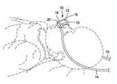
- FIG. 1is a perspective view of an infant patient also showing a CPAP device according to an embodiment of the present invention in use.
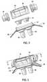
- FIG. 2is an exploded view of components of the CPAP device.
- FIG. 3is a perspective view of the device of FIG. 2 in an assembled condition.
- FIG. 4is a cross sectional view taken through line 4 - 4 in FIG. 3 of the CPAP device of FIG. 3 .
- FIG. 5is a cross sectional view taken through line 5 - 5 of FIG. 4 , showing a cross section of the CPAP device of FIG. 3 .
- Some embodimentsprovide a CPAP device and method that has reduced size, improved performance, and/or other benefits with respect to the patient. Preferred embodiments of the invention will now be described with reference to the drawing Figures in which like reference numerals refer to like parts throughout.
- FIG. 1is a perspective view of a patient using a CPAP device according to an embodiment of the present invention.
- the device 10includes a generator body 12 which receives positive airflow pressure from a supply tube 14 .
- the tube 14is pressurized by an air pressurize device which is not illustrated.
- the generator body 12also is connected to an outlet tube 15 .
- the tubing for tubes 14 and 15does not have a circular cross section, but rather has an oval or ellipsoid cross section. This oval cross section of the tubes 14 and 15 some times will provide a significant benefit, where used, in several respects.
- the oval tubingprovides a greater volumetric area while still reducing the diameter of the tubing in one direction, and also allows for a more compact generator housing 16 as described in more detail below with respect to FIGS. 2 through 4 .
- the oval tubinghas a tendency to lay flat if the patient turns his or her head and lies on the tubing. This relatively flat contact with the patient's head can be more comfortable and distribute the weight of the patient's head more evenly over the tubing as compared to circular tubing.
- some other aspects of the preferred embodiment that will be described belowcan still be obtained with the use of circular tubing.
- FIG. 1also illustrates, as will be seen in more detail in the subsequent Figures, that the generator body 12 includes a housing 16 (which has the inlet fitting 22 that connects to the tubing 14 and an outlet fitting 23 connected to the tubing 15 ) and also has an exhalation port 18 which permits outlet of the exhalation air.
- the housing 16is attached to a receiver assembly 20 which includes prongs that fit into the patient's nares as will be described further below.
- the housing 16is essentially a rectangular box-shaped housing having the exhalation port 18 , and a pair of side structures on its side ends.
- the side structureseach form sidewalls of the generator body and have the fittings 22 and 23 that receive the tubing 14 and 15 , which is preferably oval tubing, as described above.
- the receiver 20includes a pair of nasal prongs 26 extending therefrom as well as a pair of headgear attachment flanges 28 projecting therefrom.
- the receiver nasal prongs 26may be of any suitable size and shape as is suitable for interacting with the patient's nares.
- the headgear attachment flanges 28may also be of any suitable size and shape to interact with a strap type headgear or an adhesive fastening arrangement, or any other type of patient attachment system.
- the housing 18can have a relatively compact rectangular box shape, and the tubing 14 and 15 may be arranged with its major diameter at a diagonal angle, as can be seen by the orientation of the fittings 22 and 23 , thus allowing the tubing 14 and 15 to have a major diameter that is nearly as long as the diagonal length of the profile of the housing 18 . This contributes to the housing 18 having a desirably compact shape.
- the assembly described abovemay be manufactured from any suitable materials.
- the housing 18 and its fittings 22 and 23 , as well as the receiver cap 24are manufactured from a plastic, such as a polycarbonate.
- the receiver 20including the headgear attachment flanges, and nasal prongs, may be molded from a biocompatible silicone.
- Supply airenters the housing 16 via a fitting 22 from a pressurized source through the tubing 14 .
- the supply airenters a supply air channel 30 which feeds two supply air nozzle jets 32 .
- Supply air nozzle jets 32each generally have a first cylindrical portion 34 and then transition to a slight outward taper region 35 .
- the tapered portion 35is an outward flared conical taper with an included angle of approximately 4 degrees between the sidewalls. This outward taper has been found to provide a venturi effect which is beneficial to the airflow.
- the axial length of the portion 35is approximately two times the starting diameter, i.e., the internal diameter of the cylindrical portion 34 of the jet 32 . This taper improves the efficiency of the nozzle and reduces the pressure required to drive the generator.
- the jets 32direct air towards the receiver cap assembly 24 , and more particularly to two funnel shaped receivers 38 .
- the nasal prongs 26then receive air directly from the receivers 38 .
- the receivers 38each have a conically tapered portion 39 with an inward flared cone having an included angle of 60 degrees between the sidewalls.
- a straight cylindrical portion 41extends from the end of the conical portion 39 .
- a distance D from a reference line A, which is the outlet end face 36 of the jet 32 relative to reference line B, which is the end face of the conical portion of the receivers 38has been found to be 1.8 times the internal diameter of the cylindrical portion 34 of the jets 32 .
- the outlet fitting 23leads to outlet tubing by which the patient pressure can be monitored at an outlet side of the device, i.e., pressure monitoring system that is not shown.
- FIG. 5is a cross section view showing at a different angle some of the various components referred to above using the same reference numerals.
Landscapes
- Health & Medical Sciences (AREA)
- Pulmonology (AREA)
- General Health & Medical Sciences (AREA)
- Life Sciences & Earth Sciences (AREA)
- Engineering & Computer Science (AREA)
- Emergency Medicine (AREA)
- Biomedical Technology (AREA)
- Hematology (AREA)
- Heart & Thoracic Surgery (AREA)
- Animal Behavior & Ethology (AREA)
- Anesthesiology (AREA)
- Public Health (AREA)
- Veterinary Medicine (AREA)
- Otolaryngology (AREA)
- Business, Economics & Management (AREA)
- Emergency Management (AREA)
- Bioinformatics & Cheminformatics (AREA)
- Zoology (AREA)
- Respiratory Apparatuses And Protective Means (AREA)
- Measurement Of The Respiration, Hearing Ability, Form, And Blood Characteristics Of Living Organisms (AREA)
Abstract
Description
Claims (14)
Priority Applications (8)
| Application Number | Priority Date | Filing Date | Title |
|---|---|---|---|
| US11/966,805US8210182B2 (en) | 2007-12-28 | 2007-12-28 | Continuous positive airway pressure device |
| CA2647626ACA2647626C (en) | 2007-12-28 | 2008-12-19 | Continuous positive airway pressure device |
| EP08172825.5AEP2075023B1 (en) | 2007-12-28 | 2008-12-23 | Continuous positive airway pressure device |
| AU2008264199AAU2008264199B2 (en) | 2007-12-28 | 2008-12-24 | Continuous positive airway pressure device |
| JP2008332686AJP5108746B2 (en) | 2007-12-28 | 2008-12-26 | Continuous positive pressure breathing device |
| CN2008101873508ACN101474445B (en) | 2007-12-28 | 2008-12-29 | Continuous positive airway pressure device |
| US12/512,372US8371304B2 (en) | 2007-12-28 | 2009-07-30 | Continuous positive airway pressure device and method |
| US13/427,510US8528557B2 (en) | 2007-12-28 | 2012-03-22 | Continuous positive airway pressure device |
Applications Claiming Priority (1)
| Application Number | Priority Date | Filing Date | Title |
|---|---|---|---|
| US11/966,805US8210182B2 (en) | 2007-12-28 | 2007-12-28 | Continuous positive airway pressure device |
Related Child Applications (2)
| Application Number | Title | Priority Date | Filing Date |
|---|---|---|---|
| US12/512,372Continuation-In-PartUS8371304B2 (en) | 2007-12-28 | 2009-07-30 | Continuous positive airway pressure device and method |
| US13/427,510ContinuationUS8528557B2 (en) | 2007-12-28 | 2012-03-22 | Continuous positive airway pressure device |
Publications (2)
| Publication Number | Publication Date |
|---|---|
| US20090165799A1 US20090165799A1 (en) | 2009-07-02 |
| US8210182B2true US8210182B2 (en) | 2012-07-03 |
Family
ID=40525839
Family Applications (2)
| Application Number | Title | Priority Date | Filing Date |
|---|---|---|---|
| US11/966,805Active2031-01-02US8210182B2 (en) | 2007-12-28 | 2007-12-28 | Continuous positive airway pressure device |
| US13/427,510ActiveUS8528557B2 (en) | 2007-12-28 | 2012-03-22 | Continuous positive airway pressure device |
Family Applications After (1)
| Application Number | Title | Priority Date | Filing Date |
|---|---|---|---|
| US13/427,510ActiveUS8528557B2 (en) | 2007-12-28 | 2012-03-22 | Continuous positive airway pressure device |
Country Status (6)
| Country | Link |
|---|---|
| US (2) | US8210182B2 (en) |
| EP (1) | EP2075023B1 (en) |
| JP (1) | JP5108746B2 (en) |
| CN (1) | CN101474445B (en) |
| AU (1) | AU2008264199B2 (en) |
| CA (1) | CA2647626C (en) |
Cited By (8)
| Publication number | Priority date | Publication date | Assignee | Title |
|---|---|---|---|---|
| US20120174927A1 (en)* | 2007-12-28 | 2012-07-12 | Steven Duquette | Continuous positive airway pressure device |
| US20140000375A1 (en)* | 2012-06-29 | 2014-01-02 | General Electric Company | Pressure sensor assembly |
| US20150283347A1 (en)* | 2009-06-02 | 2015-10-08 | Resmed Limited | Unobtrusive nasal mask |
| US9333318B2 (en) | 2012-04-13 | 2016-05-10 | Fresca Medical, Inc. | Sleep apnea device |
| US9492086B2 (en) | 2012-03-21 | 2016-11-15 | Fresca Medical, Inc. | Apparatus, systems, and methods for treating obstructive sleep apnea |
| US10272226B2 (en) | 2012-04-13 | 2019-04-30 | Fresca Medical, Inc. | Auto-feedback valve for a sleep apnea device |
| US10307562B2 (en) | 2012-04-13 | 2019-06-04 | Fresca Medical, Inc. | Auto-feedback valve for a sleep apnea device |
| US20230044155A1 (en)* | 2020-01-13 | 2023-02-09 | Pneuma Therapeutics, Inc. | New Nasal Respiratory Apparatus |
Families Citing this family (36)
| Publication number | Priority date | Publication date | Assignee | Title |
|---|---|---|---|---|
| US7588033B2 (en) | 2003-06-18 | 2009-09-15 | Breathe Technologies, Inc. | Methods, systems and devices for improving ventilation in a lung area |
| CN1905917B (en) | 2003-08-18 | 2011-08-03 | 门罗生命公司 | Method and device for non-invasive ventilation with nasal interface |
| JP2009508645A (en) | 2005-09-20 | 2009-03-05 | ルッツ フレイテッグ, | System, method and apparatus for assisting patient breathing |
| JP5191005B2 (en) | 2006-05-18 | 2013-04-24 | ブリーズ テクノロジーズ, インコーポレイテッド | Method and device for tracheostomy |
| EP2068992B1 (en) | 2006-08-03 | 2016-10-05 | Breathe Technologies, Inc. | Devices for minimally invasive respiratory support |
| WO2008144589A1 (en) | 2007-05-18 | 2008-11-27 | Breathe Technologies, Inc. | Methods and devices for sensing respiration and providing ventilation therapy |
| EP2203206A4 (en) | 2007-09-26 | 2017-12-06 | Breathe Technologies, Inc. | Methods and devices for treating sleep apnea |
| EP2200686A4 (en) | 2007-09-26 | 2017-11-01 | Breathe Technologies, Inc. | Methods and devices for providing inspiratory and expiratory flow relief during ventilation therapy |
| US8371304B2 (en)* | 2007-12-28 | 2013-02-12 | Carefusion | Continuous positive airway pressure device and method |
| WO2009129506A1 (en) | 2008-04-18 | 2009-10-22 | Breathe Technologies, Inc. | Methods and devices for sensing respiration and controlling ventilator functions |
| US8776793B2 (en) | 2008-04-18 | 2014-07-15 | Breathe Technologies, Inc. | Methods and devices for sensing respiration and controlling ventilator functions |
| CN102196837B (en) | 2008-08-22 | 2015-09-09 | 呼吸科技公司 | Methods and devices for providing mechanical ventilation utilizing an open airway interface |
| US10252020B2 (en) | 2008-10-01 | 2019-04-09 | Breathe Technologies, Inc. | Ventilator with biofeedback monitoring and control for improving patient activity and health |
| US9132250B2 (en) | 2009-09-03 | 2015-09-15 | Breathe Technologies, Inc. | Methods, systems and devices for non-invasive ventilation including a non-sealing ventilation interface with an entrainment port and/or pressure feature |
| CN111420208B (en) | 2009-04-02 | 2023-07-04 | 呼吸科技公司 | Methods, systems and devices for non-invasive open ventilation using a gas delivery nozzle within an outer tube |
| US9962512B2 (en)* | 2009-04-02 | 2018-05-08 | Breathe Technologies, Inc. | Methods, systems and devices for non-invasive ventilation including a non-sealing ventilation interface with a free space nozzle feature |
| WO2011029074A1 (en)* | 2009-09-03 | 2011-03-10 | Breathe Technologies, Inc. | Methods, systems and devices for non-invasive ventilation including a non-sealing ventilation interface with an entrainment port and/or pressure feature |
| WO2011029073A1 (en)* | 2009-09-03 | 2011-03-10 | Breathe Technologies, Inc. | Methods, systems and devices for non-invasive ventilation including a non-sealing ventilation interface with a free space nozzle feature |
| CA2805561A1 (en) | 2010-08-09 | 2012-02-16 | Peter Iwatschenko | Device and system for delivery of an aerosol to a patient on ventilatory support |
| CA2807416C (en) | 2010-08-16 | 2019-02-19 | Breathe Technologies, Inc. | Methods, systems and devices using lox to provide ventilatory support |
| US8813746B2 (en) | 2010-09-10 | 2014-08-26 | Carefusion 303, Inc. | Nasal continuous positive airway pressure device for lowering patient work-of-breathing |
| CA2811423C (en) | 2010-09-30 | 2019-03-12 | Breathe Technologies, Inc. | Methods, systems and devices for humidifying a respiratory tract |
| US8567400B2 (en) | 2010-10-05 | 2013-10-29 | Carefusion 207, Inc. | Non-invasive breathing assistance device with flow director |
| US8607794B2 (en)* | 2010-10-05 | 2013-12-17 | Carefusion 207, Inc. | Non-invasive breathing assistance apparatus and method |
| BR112013019445A2 (en)* | 2011-01-31 | 2020-10-27 | Breathe Technologies, Inc. | methods systems and devices for ventilation using a nasal ventilation mask with a collector and a compliant inner tube and nasal seal pad assembly |
| US9084859B2 (en) | 2011-03-14 | 2015-07-21 | Sleepnea Llc | Energy-harvesting respiratory method and device |
| US9259548B2 (en)* | 2012-04-30 | 2016-02-16 | Carefusion 207, Inc. | Patient nasal interface for use with a nasal airway pressure system |
| CA2844454C (en)* | 2013-03-08 | 2017-07-11 | Teleflex Medical Incorporated | Exhalation scavenging therapy mask |
| WO2014164795A1 (en)* | 2013-03-11 | 2014-10-09 | Ohio State Innovation Foundation | Devices and methods for cooling patients |
| CN103638585B (en)* | 2013-12-06 | 2016-03-16 | 孙亚东 | A kind of breathing equipment by respiratory control |
| EP4186548A1 (en) | 2015-04-02 | 2023-05-31 | Hill-Rom Services PTE. LTD. | Mask leakage detection for a respiratory device |
| USD833599S1 (en)* | 2015-09-09 | 2018-11-13 | Neores Ab | Mask for respiratory therapies |
| ES2726283T3 (en)* | 2016-05-16 | 2019-10-03 | Air Liquide | Nasal cannula |
| RU167390U1 (en)* | 2016-06-21 | 2017-01-10 | Публичное акционерное общество "Техприбор" | DEVICE FOR NON-INVASIVE ARTIFICIAL VENTILATION OF LUNG NEWBORNS |
| US10792449B2 (en) | 2017-10-03 | 2020-10-06 | Breathe Technologies, Inc. | Patient interface with integrated jet pump |
| US10314999B1 (en) | 2018-08-23 | 2019-06-11 | Baiping Lei | Nasal breathing apparatus and method for high-flow therapy and non-invasive ventilation |
Citations (12)
| Publication number | Priority date | Publication date | Assignee | Title |
|---|---|---|---|---|
| US4782832A (en)* | 1987-07-30 | 1988-11-08 | Puritan-Bennett Corporation | Nasal puff with adjustable sealing means |
| US4915105A (en)* | 1988-10-28 | 1990-04-10 | Lee Tien Chu | Miniature respiratory apparatus |
| US5193532A (en) | 1988-12-06 | 1993-03-16 | Moa Conny P G | Device for generating by means of ejector action a continuous positive airway pressure (cpap) during spontaneous breathing |
| US6581601B2 (en)* | 1999-06-18 | 2003-06-24 | Saeed Ziaee | Nasal mask with balloon exhalation valve |
| US6626177B1 (en)* | 1999-06-18 | 2003-09-30 | Saeed Ziaee | Nasal mask |
| US20030200970A1 (en)* | 2002-04-29 | 2003-10-30 | Alex Stenzler | Infant breathing assist apparatus |
| US20040065330A1 (en) | 2002-07-15 | 2004-04-08 | Landis Robert M. | Dynamic infant nasal CPAP system and method |
| US20050011524A1 (en)* | 2003-07-17 | 2005-01-20 | Marguerite Thomlinson | Nasal interface apparatus |
| US20070074724A1 (en) | 2005-09-30 | 2007-04-05 | Steven Duquette | Venturi geometry design for flow-generator patient circuit |
| WO2007064668A2 (en) | 2005-12-02 | 2007-06-07 | Allegiance Corporation | Nasal continuous positive airway pressure device and system |
| US20100252044A1 (en)* | 2007-12-28 | 2010-10-07 | Care Fusion | Continuous positive airway pressure device and method |
| US7874293B2 (en)* | 2003-02-21 | 2011-01-25 | Resmed Limited | Nasal assembly |
Family Cites Families (7)
| Publication number | Priority date | Publication date | Assignee | Title |
|---|---|---|---|---|
| US6745770B2 (en)* | 2002-01-08 | 2004-06-08 | Resmed Limited | Flow diverter for controlling the pressure and flow rate in a CPAP device |
| US6909912B2 (en) | 2002-06-20 | 2005-06-21 | University Of Florida | Non-invasive perfusion monitor and system, specially configured oximeter probes, methods of using same, and covers for probes |
| US20060096596A1 (en) | 2004-11-05 | 2006-05-11 | Occhialini James M | Wearable system for positive airway pressure therapy |
| US7640934B2 (en)* | 2005-12-02 | 2010-01-05 | Carefusion 2200, Inc. | Infant nasal interface prong device |
| JP4710015B2 (en)* | 2006-03-01 | 2011-06-29 | 国立大学法人埼玉大学 | Nasal CPAP element |
| US20080127978A1 (en) | 2006-12-05 | 2008-06-05 | Benjamin Rubin | Pressure support system with dry electrode sleep staging device |
| US8210182B2 (en) | 2007-12-28 | 2012-07-03 | Carefusion 207, Inc. | Continuous positive airway pressure device |
- 2007
- 2007-12-28USUS11/966,805patent/US8210182B2/enactiveActive
- 2008
- 2008-12-19CACA2647626Apatent/CA2647626C/enactiveActive
- 2008-12-23EPEP08172825.5Apatent/EP2075023B1/enactiveActive
- 2008-12-24AUAU2008264199Apatent/AU2008264199B2/enactiveActive
- 2008-12-26JPJP2008332686Apatent/JP5108746B2/enactiveActive
- 2008-12-29CNCN2008101873508Apatent/CN101474445B/enactiveActive
- 2012
- 2012-03-22USUS13/427,510patent/US8528557B2/enactiveActive
Patent Citations (15)
| Publication number | Priority date | Publication date | Assignee | Title |
|---|---|---|---|---|
| US4782832A (en)* | 1987-07-30 | 1988-11-08 | Puritan-Bennett Corporation | Nasal puff with adjustable sealing means |
| US4915105A (en)* | 1988-10-28 | 1990-04-10 | Lee Tien Chu | Miniature respiratory apparatus |
| US5193532A (en) | 1988-12-06 | 1993-03-16 | Moa Conny P G | Device for generating by means of ejector action a continuous positive airway pressure (cpap) during spontaneous breathing |
| US6581601B2 (en)* | 1999-06-18 | 2003-06-24 | Saeed Ziaee | Nasal mask with balloon exhalation valve |
| US6626177B1 (en)* | 1999-06-18 | 2003-09-30 | Saeed Ziaee | Nasal mask |
| US20030200970A1 (en)* | 2002-04-29 | 2003-10-30 | Alex Stenzler | Infant breathing assist apparatus |
| US20040065330A1 (en) | 2002-07-15 | 2004-04-08 | Landis Robert M. | Dynamic infant nasal CPAP system and method |
| US7874293B2 (en)* | 2003-02-21 | 2011-01-25 | Resmed Limited | Nasal assembly |
| US20050011524A1 (en)* | 2003-07-17 | 2005-01-20 | Marguerite Thomlinson | Nasal interface apparatus |
| JP2007527271A (en) | 2003-07-17 | 2007-09-27 | バイアシス・ヘルスケア・インコーポレイテッド | Nazar interface device |
| US20070074724A1 (en) | 2005-09-30 | 2007-04-05 | Steven Duquette | Venturi geometry design for flow-generator patient circuit |
| WO2007040828A2 (en) | 2005-09-30 | 2007-04-12 | Viasys Manufacturing, Inc. | Venturi geometry design for flow-generator patient circuit |
| WO2007064668A2 (en) | 2005-12-02 | 2007-06-07 | Allegiance Corporation | Nasal continuous positive airway pressure device and system |
| US7578294B2 (en)* | 2005-12-02 | 2009-08-25 | Allegiance Corporation | Nasal continuous positive airway pressure device and system |
| US20100252044A1 (en)* | 2007-12-28 | 2010-10-07 | Care Fusion | Continuous positive airway pressure device and method |
Non-Patent Citations (3)
| Title |
|---|
| A. Lichtarowicz et al., Fourth Cranfield Fluidics Conference Mar. 17-20, 1970, held at the University of Warwick, Coventry, England, Paper B5, "Characteristics of Jet-Pipe Valves". |
| Hiroyuki Nagatomi, Office Action for Japanese Application No. 2008-322686, 4 pages, Dec. 8, 2011. |
| Web site www.flometrics.com/services/ncpap/, Flometrics Product Engineering Specializing in Fluid Dynamics and Thermodynamics, retrieved from web site Apr. 26, 2007. |
Cited By (14)
| Publication number | Priority date | Publication date | Assignee | Title |
|---|---|---|---|---|
| US20120174927A1 (en)* | 2007-12-28 | 2012-07-12 | Steven Duquette | Continuous positive airway pressure device |
| US8528557B2 (en)* | 2007-12-28 | 2013-09-10 | Carefusion 207, Inc. | Continuous positive airway pressure device |
| US10265490B2 (en)* | 2009-06-02 | 2019-04-23 | Resmed Limited | Unobtrusive nasal mask |
| US20150283347A1 (en)* | 2009-06-02 | 2015-10-08 | Resmed Limited | Unobtrusive nasal mask |
| US10974009B2 (en)* | 2009-06-02 | 2021-04-13 | ResMed Pty Ltd | Unobtrusive nasal mask |
| US11020559B2 (en) | 2009-06-02 | 2021-06-01 | ResMed Pty Ltd | Unobtrusive nasal mask |
| US11484674B2 (en) | 2009-06-02 | 2022-11-01 | ResMed Pty Ltd | Unobtrusive nasal mask |
| US11957842B2 (en)* | 2009-06-02 | 2024-04-16 | ResMed Pty Ltd | Unobtrusive nasal mask |
| US9492086B2 (en) | 2012-03-21 | 2016-11-15 | Fresca Medical, Inc. | Apparatus, systems, and methods for treating obstructive sleep apnea |
| US9333318B2 (en) | 2012-04-13 | 2016-05-10 | Fresca Medical, Inc. | Sleep apnea device |
| US10272226B2 (en) | 2012-04-13 | 2019-04-30 | Fresca Medical, Inc. | Auto-feedback valve for a sleep apnea device |
| US10307562B2 (en) | 2012-04-13 | 2019-06-04 | Fresca Medical, Inc. | Auto-feedback valve for a sleep apnea device |
| US20140000375A1 (en)* | 2012-06-29 | 2014-01-02 | General Electric Company | Pressure sensor assembly |
| US20230044155A1 (en)* | 2020-01-13 | 2023-02-09 | Pneuma Therapeutics, Inc. | New Nasal Respiratory Apparatus |
Also Published As
| Publication number | Publication date |
|---|---|
| CA2647626C (en) | 2017-02-14 |
| CA2647626A1 (en) | 2009-06-28 |
| EP2075023A1 (en) | 2009-07-01 |
| AU2008264199B2 (en) | 2013-09-26 |
| JP5108746B2 (en) | 2012-12-26 |
| US8528557B2 (en) | 2013-09-10 |
| US20090165799A1 (en) | 2009-07-02 |
| AU2008264199A1 (en) | 2009-07-16 |
| US20120174927A1 (en) | 2012-07-12 |
| CN101474445A (en) | 2009-07-08 |
| JP2009160403A (en) | 2009-07-23 |
| EP2075023B1 (en) | 2018-05-30 |
| CN101474445B (en) | 2013-01-02 |
Similar Documents
| Publication | Publication Date | Title |
|---|---|---|
| US8210182B2 (en) | Continuous positive airway pressure device | |
| US8371304B2 (en) | Continuous positive airway pressure device and method | |
| US20240307645A1 (en) | Nasal cannula | |
| US8074645B2 (en) | Apparatus and methods for providing humidity in respiratory therapy | |
| US7195018B1 (en) | Adjustable support system for nasal breathing devices | |
| US20130019870A1 (en) | Ventilation interface for sleep apnea therapy | |
| US20080185007A1 (en) | Sealing nasal cannula | |
| EP3294394B1 (en) | Liquid removal in a patient interface assembly | |
| US10589049B2 (en) | Fluid connector with exhaust valve | |
| CN218165762U (en) | Nasal and Patient Interface | |
| TW202210122A (en) | breathing aids | |
| AU785331B2 (en) | Breathing assistance apparatus |
Legal Events
| Date | Code | Title | Description |
|---|---|---|---|
| AS | Assignment | Owner name:VIASYS MANUFACTURING, INC., PENNSYLVANIA Free format text:ASSIGNMENT OF ASSIGNORS INTEREST;ASSIGNORS:DUQUETTE, STEVEN;HAN, STEVE;REEL/FRAME:020541/0536 Effective date:20080103 | |
| AS | Assignment | Owner name:CAREFUSION 207, INC., CALIFORNIA Free format text:CHANGE OF NAME;ASSIGNOR:CARDINAL HEALTH 207, INC.;REEL/FRAME:025135/0305 Effective date:20090729 Owner name:CARDINAL HEALTH 207, INC., CALIFORNIA Free format text:CHANGE OF NAME;ASSIGNOR:VIASYS MANUFACTURING, INC.;REEL/FRAME:025135/0297 Effective date:20071016 | |
| STCF | Information on status: patent grant | Free format text:PATENTED CASE | |
| CC | Certificate of correction | ||
| FPAY | Fee payment | Year of fee payment:4 | |
| AS | Assignment | Owner name:BANK OF AMERICA, N.A., AS COLLATERAL AGENT, NORTH Free format text:FIRST LIEN SECURITY AGREEMENT;ASSIGNOR:CAREFUSION 207, INC.;REEL/FRAME:045968/0497 Effective date:20180416 Owner name:WILMINGTON TRUST, NATIONAL ASSOCIATION, AS COLLATE Free format text:SECOND LIEN SECURITY AGREEMENT;ASSIGNOR:CAREFUSION 207, INC.;REEL/FRAME:045969/0482 Effective date:20180416 | |
| AS | Assignment | Owner name:WILMINGTON TRUST, NATIONAL ASSOCIATION, MINNESOTA Free format text:SECURITY INTEREST;ASSIGNOR:CAREFUSION 207, INC.;REEL/FRAME:049109/0656 Effective date:20190503 | |
| MAFP | Maintenance fee payment | Free format text:PAYMENT OF MAINTENANCE FEE, 8TH YEAR, LARGE ENTITY (ORIGINAL EVENT CODE: M1552); ENTITY STATUS OF PATENT OWNER: LARGE ENTITY Year of fee payment:8 | |
| AS | Assignment | Owner name:VYAIRE MEDICAL 207, INC., ILLINOIS Free format text:CHANGE OF NAME;ASSIGNOR:CAREFUSION 207, INC.;REEL/FRAME:059852/0577 Effective date:20210401 | |
| AS | Assignment | Owner name:VYAIRE MEDICAL 211, INC., ILLINOIS Free format text:MERGER;ASSIGNOR:VYAIRE MEDICAL 207, INC.;REEL/FRAME:061329/0785 Effective date:20220411 | |
| MAFP | Maintenance fee payment | Free format text:PAYMENT OF MAINTENANCE FEE, 12TH YEAR, LARGE ENTITY (ORIGINAL EVENT CODE: M1553); ENTITY STATUS OF PATENT OWNER: LARGE ENTITY Year of fee payment:12 | |
| AS | Assignment | Owner name:ZOLL MEDICAL CORPORATION, MASSACHUSETTS Free format text:ASSIGNMENT OF ASSIGNORS INTEREST;ASSIGNOR:VYAIRE MEDICAL 211, INC.;REEL/FRAME:069454/0907 Effective date:20241011 | |
| AS | Assignment | Owner name:ZOLL MEDICAL CORPORATION, MASSACHUSETTS Free format text:RELEASE BY SECURED PARTY;ASSIGNOR:VYAIRE MEDICAL, INC., ET AL.'S CREDITORS;REEL/FRAME:069635/0201 Effective date:20240903 |