US8210173B2 - Breathing assistance system having integrated electrical conductors communicating data - Google Patents
Breathing assistance system having integrated electrical conductors communicating dataDownload PDFInfo
- Publication number
- US8210173B2 US8210173B2US11/537,326US53732606AUS8210173B2US 8210173 B2US8210173 B2US 8210173B2US 53732606 AUS53732606 AUS 53732606AUS 8210173 B2US8210173 B2US 8210173B2
- Authority
- US
- United States
- Prior art keywords
- electrical
- patient
- gas delivery
- delivery apparatus
- patient interface
- Prior art date
- Legal status (The legal status is an assumption and is not a legal conclusion. Google has not performed a legal analysis and makes no representation as to the accuracy of the status listed.)
- Active, expires
Links
- 239000004020conductorSubstances0.000titleclaimsabstractdescription99
- 230000029058respiratory gaseous exchangeEffects0.000titleclaimsdescription89
- 238000004891communicationMethods0.000claimsdescription7
- 238000000034methodMethods0.000claimsdescription5
- 230000009977dual effectEffects0.000claims2
- 239000007789gasSubstances0.000description148
- 238000003780insertionMethods0.000description7
- 230000037431insertionEffects0.000description7
- 238000009423ventilationMethods0.000description7
- 208000008784apneaDiseases0.000description4
- 210000003437tracheaAnatomy0.000description4
- 230000037361pathwayEffects0.000description3
- IJGRMHOSHXDMSA-UHFFFAOYSA-NAtomic nitrogenChemical compoundN#NIJGRMHOSHXDMSA-UHFFFAOYSA-N0.000description2
- 241001274216NasoSpecies0.000description2
- QVGXLLKOCUKJST-UHFFFAOYSA-Natomic oxygenChemical compound[O]QVGXLLKOCUKJST-UHFFFAOYSA-N0.000description2
- 239000011248coating agentSubstances0.000description2
- 238000000576coating methodMethods0.000description2
- 230000008878couplingEffects0.000description2
- 238000010168coupling processMethods0.000description2
- 238000005859coupling reactionMethods0.000description2
- -1e.g.Substances0.000description2
- 239000012530fluidSubstances0.000description2
- 238000010438heat treatmentMethods0.000description2
- 239000000463materialSubstances0.000description2
- 238000012544monitoring processMethods0.000description2
- 239000001301oxygenSubstances0.000description2
- 229910052760oxygenInorganic materials0.000description2
- 239000004033plasticSubstances0.000description2
- 229920000642polymerPolymers0.000description2
- 241001465754MetazoaSpecies0.000description1
- 240000005561Musa balbisianaSpecies0.000description1
- 235000018290Musa x paradisiacaNutrition0.000description1
- 239000003570airSubstances0.000description1
- 230000004075alterationEffects0.000description1
- 238000009833condensationMethods0.000description1
- 230000005494condensationEffects0.000description1
- 239000003814drugSubstances0.000description1
- 229940079593drugDrugs0.000description1
- 230000005611electricityEffects0.000description1
- 230000001815facial effectEffects0.000description1
- 238000001990intravenous administrationMethods0.000description1
- 210000004072lungAnatomy0.000description1
- 238000005399mechanical ventilationMethods0.000description1
- 238000012806monitoring deviceMethods0.000description1
- 239000006199nebulizerSubstances0.000description1
- 229910052757nitrogenInorganic materials0.000description1
- 210000003800pharynxAnatomy0.000description1
- 238000012545processingMethods0.000description1
- 239000000126substanceSubstances0.000description1
- 238000006467substitution reactionMethods0.000description1
- XLYOFNOQVPJJNP-UHFFFAOYSA-NwaterSubstancesOXLYOFNOQVPJJNP-UHFFFAOYSA-N0.000description1
Images


Classifications
- A—HUMAN NECESSITIES
- A61—MEDICAL OR VETERINARY SCIENCE; HYGIENE
- A61M—DEVICES FOR INTRODUCING MEDIA INTO, OR ONTO, THE BODY; DEVICES FOR TRANSDUCING BODY MEDIA OR FOR TAKING MEDIA FROM THE BODY; DEVICES FOR PRODUCING OR ENDING SLEEP OR STUPOR
- A61M16/00—Devices for influencing the respiratory system of patients by gas treatment, e.g. ventilators; Tracheal tubes
- A61M16/08—Bellows; Connecting tubes ; Water traps; Patient circuits
- A61M16/0816—Joints or connectors
- A—HUMAN NECESSITIES
- A61—MEDICAL OR VETERINARY SCIENCE; HYGIENE
- A61M—DEVICES FOR INTRODUCING MEDIA INTO, OR ONTO, THE BODY; DEVICES FOR TRANSDUCING BODY MEDIA OR FOR TAKING MEDIA FROM THE BODY; DEVICES FOR PRODUCING OR ENDING SLEEP OR STUPOR
- A61M16/00—Devices for influencing the respiratory system of patients by gas treatment, e.g. ventilators; Tracheal tubes
- A61M16/04—Tracheal tubes
- A—HUMAN NECESSITIES
- A61—MEDICAL OR VETERINARY SCIENCE; HYGIENE
- A61M—DEVICES FOR INTRODUCING MEDIA INTO, OR ONTO, THE BODY; DEVICES FOR TRANSDUCING BODY MEDIA OR FOR TAKING MEDIA FROM THE BODY; DEVICES FOR PRODUCING OR ENDING SLEEP OR STUPOR
- A61M16/00—Devices for influencing the respiratory system of patients by gas treatment, e.g. ventilators; Tracheal tubes
- A61M16/08—Bellows; Connecting tubes ; Water traps; Patient circuits
- A61M16/0816—Joints or connectors
- A61M16/0833—T- or Y-type connectors, e.g. Y-piece
- A—HUMAN NECESSITIES
- A61—MEDICAL OR VETERINARY SCIENCE; HYGIENE
- A61M—DEVICES FOR INTRODUCING MEDIA INTO, OR ONTO, THE BODY; DEVICES FOR TRANSDUCING BODY MEDIA OR FOR TAKING MEDIA FROM THE BODY; DEVICES FOR PRODUCING OR ENDING SLEEP OR STUPOR
- A61M16/00—Devices for influencing the respiratory system of patients by gas treatment, e.g. ventilators; Tracheal tubes
- A61M16/10—Preparation of respiratory gases or vapours
- A61M16/1075—Preparation of respiratory gases or vapours by influencing the temperature
- A61M16/1095—Preparation of respiratory gases or vapours by influencing the temperature in the connecting tubes
- A—HUMAN NECESSITIES
- A61—MEDICAL OR VETERINARY SCIENCE; HYGIENE
- A61M—DEVICES FOR INTRODUCING MEDIA INTO, OR ONTO, THE BODY; DEVICES FOR TRANSDUCING BODY MEDIA OR FOR TAKING MEDIA FROM THE BODY; DEVICES FOR PRODUCING OR ENDING SLEEP OR STUPOR
- A61M16/00—Devices for influencing the respiratory system of patients by gas treatment, e.g. ventilators; Tracheal tubes
- A61M16/04—Tracheal tubes
- A61M16/0434—Cuffs
- A—HUMAN NECESSITIES
- A61—MEDICAL OR VETERINARY SCIENCE; HYGIENE
- A61M—DEVICES FOR INTRODUCING MEDIA INTO, OR ONTO, THE BODY; DEVICES FOR TRANSDUCING BODY MEDIA OR FOR TAKING MEDIA FROM THE BODY; DEVICES FOR PRODUCING OR ENDING SLEEP OR STUPOR
- A61M2205/00—General characteristics of the apparatus
- A61M2205/60—General characteristics of the apparatus with identification means
- A61M2205/6027—Electric-conductive bridges closing detection circuits, with or without identifying elements, e.g. resistances, zener-diodes
Definitions
- the present disclosurerelates generally to the field of medical devices, e.g., a breathing assistance system having integrated electrical conductors for communicating data.
- Conventional breathing assistance systemstypically include a gas delivery system, a patient interface to deliver gas to one or more breathing passages of the patient, and a connection system between the gas delivery system and the patient interface.
- breathing assistance systemsmay be used, e.g., for mechanical ventilation of a patient's lungs and/or treatment of an apnea or other medical condition.
- Calibration and operation of such breathing assistance systemsmay depend on the physical characteristics (e.g., geometric dimensions) of the various system components, vital statistics of the patient, atmospheric conditions in the treatment area and/or any other relevant parameters.
- Traditional implementationmay include programming by a technician or other personnel and/or may include dedicated system components which are preset to interface with a limited number of alternative components.
- a patient interfacetypically includes a patient end configured for insertion into or otherwise interfacing with one or more breathing passageways of a patient and a connection end configured for receiving gas communicated by a gas delivery apparatus and delivering gas to the patient.
- a patient interfaceis an endotracheal tube including a tube portion and an inflatable cuff coupled to the tube portion. The inflatable cuff may provide a seal against escaping gas after the tube is inserted into a patient's breathing passageway, such as through a tracheostomy, nose and/or mouth.
- Another example of a patient interfaceis a mask sealed to the patient's mouth and/or nose.
- a medical devicemay include a gas delivery apparatus, a patient interface, a connection system, and an electrical circuit.
- the gas delivery apparatusmay be configured to deliver gas to a patient.
- the patient interfacemay be configured to interface with the patient to deliver gas communicated by the gas delivery apparatus to the patient.
- the connection systemmay be configured to communicate gas from the gas delivery apparatus to the patient interface.
- the electrical circuitmay be configured to communicate electrical signals between the patient interface and the gas delivery apparatus, and may including one or more first electrical conductors at least partially integral with the patient interface and one or more second electrical conductors at least partially integral with the connection system.
- a medical devicemay include a breathing circuit and an electrical conductor.
- the breathing circuitmay be configured for use in providing breathing assistance to a patient and may be configured to be communicatively coupled to a gas delivery apparatus.
- the electrical conductormay be at least partially integrated with the breathing circuit, and may be configured to form a portion of an electrical circuit for communicating electrical signals between the breathing circuit and the gas delivery apparatus.
- a medical devicemay include a gas delivery apparatus for delivering gas toward a patient and a connection interface configured to connect to a breathing circuit and receive electrical signals via one or more conductors at least partially integrated in the breathing circuit.
- a medical devicemay include a gas delivery means, a patient interfacing means, a connection means, and a signal communication means.
- the gas delivery meansmay be configured for delivering gas to a patient.
- the patient interfacing meansmay be configured for interfacing with the patient to deliver gas communicated by the gas delivery means to the patient.
- the connection meansmay be configured for communicating gas from the gas delivery means to the patient interfacing means.
- the signal communication meansmay be configured for communicating electrical signals between the patient interfacing means and the gas delivery means, and may include one or more first electrical conductors at least partially integral with the patient interfacing means and one or more second electrical conductors at least partially integral with the connection means.
- a method of communicating data in a breathing assistance systemmay include operating a breathing system, in which the breathing system includes a gas delivery apparatus, a patient interface, a connection system, and an electrical circuit configured to communicate electrical signals between the patient interface and the gas delivery apparatus, and communicating data between the patient interface and the gas delivery apparatus via the electrical circuit.
- the gas delivery apparatusmay be configured to deliver gas to a patient.
- the patient interfacemay be configured to interface with the patient to deliver gas from the gas delivery apparatus to the patient.
- the connection systemmay be configured to communicate gas from the gas delivery apparatus to the patient interface.
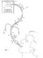
- FIG. 1illustrates an example breathing assistance system having one or more integrated electrical circuits for communicating electrical signals, according to one embodiment of the present disclosure
- FIG. 2Aillustrates an example connection system having one or more integrated electrical conductors for communicating electrical signals between a patient interface and a gas delivery apparatus, according to one embodiment of the present disclosure
- FIG. 2Billustrates an example connection system having one or more integrated electrical conductors for communicating electrical signals between electronic devices integral with the connection system and a gas delivery apparatus, according to one embodiment of the present disclosure
- FIG. 3illustrates an example tracheal tube having one or more integrated electrical conductors and one or more integrated electronic devices, according to one embodiment of the present disclosure
- FIG. 4illustrates an example patient mask having one or more integrated electrical conductors and one or more integrated electronic devices, according to another embodiment of the present disclosure
- FIG. 5illustrates an example breathing assistance system including a dual-limb connection system, according to one embodiment of the present disclosure
- FIG. 6illustrates an example “Y” connector for a dual-limb connection system and having one or more integrated electrical conductors, according to one embodiment of the present disclosure
- FIG. 7illustrates example physical alignment keys for aligning electrical contacts of different components of a breathing assistance system, according to one embodiment of the present disclosure
- FIG. 8illustrates example physical alignment keys for aligning electrical contacts of different components of a breathing assistance system, according to another embodiment of the present disclosure.
- FIG. 9illustrates an example gas delivery apparatus including an output port, a connection component, and a logic control unit, according to another embodiment of the present disclosure.
- breathing assistance systemse.g., ventilators, CPAP systems, or BiPAP systems
- breathing assistance systemse.g., ventilators, CPAP systems, or BiPAP systems
- passagewayse.g., the mouth, nose, trachea and/or pharynx
- breathing assistancee.g., providing ventilation and/or treating an apnea or other breathing condition
- a breathing assistance systemmay include a gas delivery apparatus (e.g., a ventilator, CPAP device, or BiPAP device), a patient interface (e.g., a tracheal tube or a mask), a connection system (e.g., a single-limb or a dual-limb breathing circuit) between the gas delivery apparatus and the patient interface, and an electrical circuit (e.g., one or more wires and/or other conductors) extending from the patient interface, through the connection system, and to the gas delivery apparatus for communicating electrical signals between the patient interface and the gas delivery apparatus.
- the electrical circuitmay include one or more electrical conductors integral with the patient interface and/or one or more electrical conductors integral with the connection system.
- a patient interfacefor use in a breathing assistance system may include a connection end configured for receiving gas communicated by a gas delivery apparatus (e.g., a ventilator, CPAP device, or BiPAP device), and a patient end configured for insertion into or more breathing passageways of a patient (e.g., trachea, nose and/or mouth).
- a gas delivery apparatuse.g., a ventilator, CPAP device, or BiPAP device
- An electronic devicemay be integrated with or otherwise coupled to the patient interface, and one or more electrical conductors may be at least partially integrated with the patient interface for facilitating communication of electrical signals between the electronic device and the gas delivery apparatus.
- FIG. 1illustrates an example breathing assistance system 10 for providing breathing assistance to a patient 12 , according to one embodiment of the disclosure.
- Breathing assistance system 10may be generally configured to provide breathing assistance (e.g., providing ventilation and/or treating an apnea or other breathing condition) to a patient 12 .
- Breathing assistance system 10may include a gas delivery apparatus 14 , a patient interface 16 , a connection system 18 between gas delivery apparatus 14 and patient interface 16 , and an integrated electrical circuit 20 for communicating electrical signals between connection system 18 and gas delivery apparatus 14 and/or between patient interface 16 and gas delivery apparatus 14 .
- Gas delivery apparatus 14may include any device or devices configured to generate, supply, and/or deliver gas (e.g., pressurized air) toward patient 12 via patient interface 16 .
- gas delivery apparatus 14may comprise a device capable of generating pressurized air (e.g., a ventilator, CPAP system, or BiPAP system), a wall outlet through which pressurized air may be supplied (e.g., in a hospital or clinic), one or more tanks of compressed gas, a compressor, or any other suitable source of pressurized or non-pressurized gas.
- gasmay refer to any one or more gases and/or vaporized substances suitable to be delivered to and/or from a patient via one or more breathing orifices (e.g., the nose and/or mouth), such as air, nitrogen, oxygen, any other component of air, CO 2 , vaporized water, vaporized medicines, and/or any combination of two or more of the above, for example.
- breathing orificese.g., the nose and/or mouth
- the term “patient”may refer to any person or animal that may receive breathing assistance from system 10 , regardless of the medical status, official patient status, physical location, or any other characteristic of the person.
- patientsmay include persons under official medical care (e.g., hospital patients), persons not under official medical care, persons receiving care at a medical care facility, persons receiving home care, etc.
- Gas delivery apparatus 14may include an connection interface 21 configured to communicate gas toward a patient.
- connection interface 21may comprise a device capable of releasing gas to the atmosphere (e.g., a hole, a slit, a valve, and/or any other fluid passage), and/or a device capable of communicating gas from gas delivery apparatus 14 to connection system 18 or other tubes or conduits.
- Gas delivery apparatus 14may include a gas delivery control system 22 operable to control the breathing assistance provided by gas delivery apparatus 14 based on various input.
- gas delivery control system 22may regulate the pressure and/or flow of gas delivered to patient 12 based on various input (e.g., data received from sensors and/or input from a user).
- Gas delivery control system 22may include, or have access to, one or more processors, memory devices, and any other suitable hardware or software.
- the one or more memory devicesmay store instructions (e.g., any suitable software, algorithms, or other logic or instructions that may be executed by one or more processors) for controlling the operation of gas delivery apparatus 14 , e.g., controlling ventilation support provided by gas delivery apparatus 14 .
- Gas delivery apparatus 14may further include any other components suitable for providing functionality related to providing breathing assistance to a patient 12 .
- gas delivery apparatus 14may include one or more display devices for displaying various information regarding system 10 (e.g., data regarding patient 12 , the operation of gas delivery apparatus 14 , and/or any other relevant data), one or more sensors, a humidifier, a nebulizer, an alarm system, and/or any other suitable components.
- Patient interface 16may include any device or devices configured to interface with patient 12 to deliver gas to patient 12 .
- patient interface 16may include a patient connection tube directly connected to the patient's trachea, an artificial airway (e.g., an endotracheal tube or other device) inserted in the patient's trachea, and/or a mask or nasal pillows positioned over the patient's nose and/or mouth.
- the patient connection tubemay include a wye (or “Y”) connector.
- Connection system 18may include any suitable means for connecting gas delivery apparatus 14 to patient interface 16 .
- Connection system 18may include one or more tubes, hoses, or other conduits suitable to communicate gas.
- Such tubes, hoses, or other conduitsmay be formed from any suitable materials, e.g., plastic, rubber, or other polymers, and may be generally flexible or generally rigid.
- connection system 18may comprise a breathing circuit including a flexible inspiration conduit and/or a flexible exhalation conduit.
- connection system 18may comprise a single-limb or a dual-limb breathing circuit.
- system 10When assembled, system 10 may define one or more gas delivery passageways from gas delivery apparatus 14 , through connection system 18 , and through patient interface 16 . Such passageways may be used to deliver gas from gas delivery apparatus 14 to patient 12 .
- patient interface 16 and/or connection system 18may include or define one or more passageways for communicating exhaled gas away from patient 12 .
- system 10may include one or more connectors 24 for connecting connection system 18 to gas delivery apparatus 14 and/or to patient interface 16 .
- connectors 24may be removably attachable to gas delivery apparatus 14 , patient interface 16 , and/or connection system 18 .
- connection system 18may be coupled directly to gas delivery apparatus 14 and patient interface 16 without such connectors 24 .
- System 10may also include one or more electronic devices 25 coupled to patient interface 16 , connection system 18 , and/or connectors 24 .
- Electronic devices 25may include any devices capable of generating electrical signals, which signals may be communicated via one or more electrical circuits 20 (e.g., between patient interface 16 and gas delivery apparatus 14 or between connection system 18 and gas delivery apparatus 14 ).
- electronic devices 25may include one or more sensors 26 , memory devices 28 , and/or signal processors 30 , each discussed below in greater detail.
- one or more electronic devices 25may be at least partially integrated with patient interface 16 , connection system 18 , and/or connectors 24 .
- one or more electronic devices 25may be otherwise coupled to patient interface 16 , connection system 18 , and/or connectors 24 .
- Sensors 26may include any device or devices for sensing, detecting, and/or monitoring one or more parameters related to the ventilation of patient 12 , e.g., parameters regarding the ventilation provided by gas delivery apparatus 14 and/or physiological parameters regarding patient 12 .
- sensors 26may include one or more devices for measuring various parameters of gas flowing into or out of patient 12 or gas delivery apparatus 14 , e.g., the pressure, flow rate, flow volume, temperature, gas content, and/or humidity of such gas flow.
- sensors 26may include, e.g., one or more pressure sensors, flow meters, transducers, and/or oxygen sensors.
- Sensors 26may be located at one or more various locations in breathing assistance system 10 for monitoring the pressure and or flow of gasses flowing into and/or out of patient 12 and/or gas delivery apparatus 14 .
- one or more sensors 26may be integrated with or located in or proximate gas delivery apparatus 14 , connection system 18 , and/or patient interface 16 .
- one or more sensors 26may be at least partially integrated with or otherwise coupled to patient interface 16 , to provide access to patient parameters (e.g., core temperature, tracheal pressure, tissue pH, and/or other measurable parameters).
- patient parameterse.g., core temperature, tracheal pressure, tissue pH, and/or other measurable parameters.
- patient interface 16comprises a tracheal tube, an oro/naso tracheal tube and/or a mask
- one or more sensors 26e.g., a thermistor, a pH electrode and/or a pressure transducer
- a pressure transducermay be integrated with or located in or proximate the tube or mask.
- Example configurationsinclude, but are not limited to, sensors 26 integrated within a sidewall of patient interface 16 , secured to the internal or external surface of a sidewall of patient interface 16 , and/or attached or otherwise associated with any component of patient interface 16 , connection system 18 and/or connectors 24 .
- Memory devices 28may include any device or devices for recording and/or storing parameters related to the various components of connection system 18 or patient interface 16 .
- a memory device 28may store physical and/or geometric parameters of one or more components of connection system 18 or patient interface 16 (e.g., values for an inner diameter and/or length of a component of connection system 18 ).
- a memory device 28may store an identifier (e.g., a serial number, device code and/or other code) for identifying the type (or the particular unit) of a particular connection system 18 or patient interface 16 .
- an identifiere.g., a serial number, device code and/or other code
- a memory device 28may store data for identifying one or more other electronic devices 25 coupled to the particular connection system 18 or patient interface 16 .
- a memory device 28 integrated in a patient interface 16may store data indicating that patient interface 16 includes a flow sensor and a pressure sensor.
- a memory device 28may store data for identifying the number and or type(s) of data channels provided by the particular connection system 18 or patient interface 16 .
- a memory device 28 integrated in a connection system 18may store data indicating that the connection system 18 includes three data channels for communicating three channels of data between patient interface 16 and gas delivery apparatus 14 .
- one or more memory devices 28may be at least partially integrated with or otherwise coupled to patient interface 16 , connection system 18 and/or connectors 24 .
- patient interface 16comprises a tracheal tube, an oro/naso tracheal tube and/or a mask
- one or more memory devices 28may be integrated with or located in or proximate the tube or mask.
- Example configurationsinclude, but are not limited to, memory devices 28 integrated within a sidewall of patient interface 16 , secured to the internal or external surface of a sidewall of patient interface 16 , and/or attached or otherwise associated with any component of patient interface 16 , connection system 18 and/or connectors 24 .
- Signal processors 30may include any device or devices for processing signals received from one or more electrical devices 25 (e.g., one or more sensors 26 and/or one or more memory devices 28 ), e.g., converting analog signals to digital signals, and/or interpreting identifiers (e.g., serial numbers, device codes and/or other codes) of various components of connection system 18 or patient interface 16 .
- a signal processor 30may include a device configured to interrogate one or more memory devices 28 and to generate signals indicating the results of such interrogation that may be communicated to gas delivery apparatus 14 via an integrated electrical circuit 20 .
- a signal processor 30may include a device configured to receive a signal generated by one or more sensors 26 , analyze the received signal, and/or convert the signal to a format suitable for communication to gas delivery apparatus 14 (e.g., a format readable by gas delivery control system 22 ).
- one or more signal processors 30may be located within or proximate gas delivery device 14 , connection system 18 and/or patient interface 16 .
- Example configurationsinclude, but are not limited to, signal processors 30 integrated within a sidewall of patient interface 16 , secured to the internal or external surface of a sidewall of patient interface 16 , and/or attached or otherwise associated with any component of patient interface 16 , connection system 18 and/or connectors 24 .
- system 10may include one or more electrical circuits 20 for communicating electrical signals between connection system 18 and gas delivery apparatus 14 and/or between patient interface 16 and gas delivery apparatus 14 .
- one or more electrical circuits 20may be configured to communicate signals from one or more sensors 26 , memory devices 28 , and/or signal processors 30 to gas delivery apparatus 14 .
- An electrical circuit 20may comprise one, two, or more conductive pathways configured to communicate electrical signals between two points in either one direction or both directions.
- An electrical circuit 20may include any number of electrically conductive elements (referred to herein as “conductors”) connected to form a conductive pathway.
- an electrical circuit 20may include one or more patient interface conductors 34 at least partially integrated with patient interface 16 , one or more connection system conductors 36 at least partially integrated with connection system 18 , and/or one or more connector conductors 37 at least partially integrated with one or more connectors 24 .
- An electrical circuit 20may also include any other conductors for completing the circuit 20 , e.g., one or more conductors integrated or otherwise associated with one or more connectors 24 between connection system 18 and to patient interface 16 and/or between connection system 18 and gas delivery apparatus 14 .
- Each conductormay comprise any element operable to communicate electrical signals.
- conductorsmay include wires (insulated or non-insulated), conductive vias, printed circuits and/or any other element that contains movable charges of electricity.
- Patient interface conductors 34may communicate electrical signals to and/or from one or more electronic devices (e.g., one or more sensors 26 , memory devices 28 , and/or signal processors 30 ), and may terminate in electrical contacts configured to mate with electrical contacts associated with connection system 18 and/or a connector 24 between patient interface 16 and connection system 18 .
- patient interface conductors 34may be at least partially integrated with patient interface 16 .
- a patient interface conductor 34may be integrated or embedded within, or secured to an internal or external surface of, a sidewall of patient interface 16 .
- a patient interface conductor 34be integrated or embedded within an insulating tube or coating and may run within or coupled to patient interface 16 .
- a patient interface conductor 34may be integrated or embedded within a side wall of the tube, or may otherwise run along a length of the tube within the tube. Example embodiments are discussed in greater detail below with reference to FIGS. 3 and 4 .
- connection system conductors 36may communicate electrical signals from a first end of connection system 18 to a second end of connection system 18 in order to support communications between patient interface 16 and gas delivery apparatus 14 .
- connection system conductors 36may terminate in first electrical contacts proximate a first end of connection system 18 and in second electrical contacts proximate a second end of connection system 18 , as discussed in greater detail below with reference to FIG. 2A .
- connection system conductors 36may communicate electrical signals to and/or from such electronic devices 25 .
- a connection system conductor 36may extend from an electronic device 25 and terminate in an electrical contact proximate one end of connection system 18 , as discussed in greater detail below with reference to FIG. 2B .
- connection system conductors 36may be at least partially integrated with connection system 18 .
- a connection system conductor 36may be integrated or embedded within, or secured to an internal or external surface of, a sidewall of connection system 18 .
- a connection system conductor 36may be integrated or embedded within an insulating tube or coating and may run within or coupled to connection system 18 .
- a connection system conductor 36may be integrated or embedded within a side wall of the inspiration conduit and/or exhalation conduit, or may otherwise run along a length of and within the inspiration conduit and/or exhalation conduit. Example embodiments are discussed in greater detail below with reference to FIGS. 2A and 2B .
- gas delivery control system 22may be operable to control the ventilation support provided by gas delivery apparatus 14 based on various input.
- Such inputmay include input received from an operator (e.g., via a touch screen and/or other user interfaces provided by gas delivery apparatus 14 ) and/or data received from one or more electronic devices 25 (e.g., sensors 26 , memory devices 28 , and/or signal processors 30 ) via one or more electrical circuits 20 .
- gas delivery control system 20may regulate the pressure, flow, and/or any other parameter of breathing gas delivered to patient 12 based at least on a signal received via one or more electrical circuits 20 from one or more sensors 26 , e.g., data regarding pressure, flow, temperature, humidity, pH, and/or any other relevant parameter.
- gas delivery control system 20may regulate the pressure, flow, and/or any other parameter of breathing gas delivered to patient 12 based at least on a signal received via one or more electrical circuits 20 from one or more memory devices 28 , e.g., data identifying various physical or other characteristics of the patient interface 16 or connection system 18 .
- gas delivery control system 20may regulate the pressure, flow, and/or any other parameter of breathing gas delivered to patient 12 based at least on a signal received via one or more electrical circuits 20 from one or more signal processors 30 (e.g., data identifying various physical or other characteristics of the patient interface 16 or connection system 18 and/or data regarding pressure, flow, temperature, humidity, pH, and/or any other relevant parameter).
- Connection interface 21 of gas delivery apparatus 14may by configured to provide both (a) a physical interface (e.g., a physical outlet) for coupling connection system 18 to gas delivery apparatus 14 (thus communicatively coupling patient interface 16 to gas delivery apparatus 14 ), and (b) an electrical interface for connecting one or more connection system conductors 36 to internal components of gas delivery apparatus 14 (e.g., gas delivery control system 22 ).
- the electrical interfacemay thus be configured for communicating electrical signals between internal components of gas delivery apparatus 14 (e.g., gas delivery control system 22 ) and one or more electronic devices 25 via one or more integrated electrical circuits 20 .
- gas delivery control system 22may receive signals from an electronic device 25 via an integrated electrical circuit 20 and connection interface 21 , and control one or more functions of gas delivery apparatus 14 (e.g., the pressure, flow, and/or other parameter of gas delivered by gas delivery apparatus 14 ) based at least on the received electrical signals.
- gas delivery apparatus 14e.g., the pressure, flow, and/or other parameter of gas delivered by gas delivery apparatus 14
- FIG. 2Aillustrates an example connection system 18 having one or more integrated connection system conductors 36 for communicating signals between gas delivery apparatus 14 and patient interface 16 , according to one embodiment of the present disclosure.
- Connection system 18may define a conduit capable of communicating gas between gas delivery apparatus 14 and patient interface 16 .
- connection system 18may include one or more hoses 38 having a side wall 42 .
- Hosesmay be generally flexible or rigid, and may be formed from any suitable materials, e.g., plastic, rubber, or other polymers.
- one or more connection system conductors 36 configured to communicate electrical signals between patient interface 16 and gas delivery apparatus 14may be embedded and/or otherwise integral with side wall 42 for at least a portion of the length of connection system 18 .
- connection system conductors 36may be embedded and/or otherwise integral with side wall 42 for the complete length of connection system 18 (i.e., from a first end to a second end of connection system 18 ).
- one or more connection system conductors 36may be integrated or embedded within an insulating tube running within or coupled to connection system 18 .
- connection system 18may include additional components operable to complete integrated electrical circuit 20 .
- connection system conductors 36may terminate in first electrical contacts 40 A proximate a first end of connection system 18 and in second electrical contacts 40 B proximate a second end of connection system 18 .
- Electrical contacts 40 Amay be configured to connect to corresponding electrical contacts associated with patient interface 16 (or with a connector 24 between connection system 18 and patient interface 16 ) to provide an electrical connection between connection system 18 and patient interface 16 .
- Electrical contacts 40 Bmay be configured to connect to corresponding electrical contacts associated with gas delivery apparatus 14 (or with a connector 24 between connection system 18 and gas delivery apparatus 14 ) to provide an electrical connection between connection system 18 and gas delivery apparatus 14 .
- electrical contacts 40 A and or 40 Bmay be positioned around the perimeter of either end of hose 38 .
- connection system 18may also include one or more heating conductors 44 that may be configured to heat the gas flowing through connection system 18 , e.g., to prevent or reduce condensation from humidified gasses. In other embodiments, connection system 18 may not include such heating conductors 44 .
- FIG. 2Billustrates an example connection system 18 having one or more integrated connection system conductors 36 for communicating signals between one or more electronic devices 25 (e.g., sensors 26 , memory devices 28 , and/or signal processors 30 ) and gas delivery apparatus 14 , according to one embodiment of the present disclosure.
- Connection system conductors 36may be embedded and/or otherwise integral with side wall 42 for at least a portion of the length of connection system 18 .
- one or more connection system conductors 36may be embedded and/or otherwise integral with side wall 42 for the complete length extending from the relevant electronic devices 25 to one end of connection system 18 .
- one or more connection system conductors 36may be integrated or embedded within an insulating tube running within or coupled to connection system 18 .
- connection system conductor 36may terminate in an electrical contact 40 proximate one end of connection system 18 .
- Electrical contacts 40may be configured to connect to corresponding electrical contacts associated with gas delivery apparatus 14 (or with a connector 24 between connection system 18 and gas delivery apparatus 14 ) to provide an electrical connection between connection system 18 and gas delivery apparatus 14 .
- electrical contacts 40may be positioned around the perimeter of the end of hose 38 .
- FIG. 3illustrates an example embodiment of patient interface 16 in which patient interface 16 is a tracheal tube.
- Tracheal tube 16may include one or more integral patient interface conductors 34 for communicating signals to and/or from one or more electronic devices 25 (e.g., sensors 26 , memory devices 28 , and/or signal processors 30 ) integral with tracheal tube 16 .
- electronic devices 25e.g., sensors 26 , memory devices 28 , and/or signal processors 30
- Tracheal tube 16may include tubular body 50 having at least one side wall 52 .
- Tube 16may include a connection end 54 configured for receiving gas from gas delivery apparatus 14 , and a patient end 56 configured for insertion into one or more breathing passageways of patient 12 .
- one or more patient interface conductors 34may be embedded in or otherwise integral with side wall 52 .
- one or more patient interface conductors 34may be integrated or embedded within an insulating tube running within or coupled to tubular body 50 .
- Patient interface conductors 34may run from one or more electronic devices 25 integral with or otherwise associated with tube 16 , and may terminate in one or more electrical contacts 40 proximate an end of tube 16 .
- Electrical contacts 40may be configured to connect to corresponding electrical contacts associated with connection system 18 (or with a connector 24 between connection system 18 and tube 16 ) to provide an electrical connection between tube 16 and connection system 18 .
- electrical contacts 40may be positioned around the perimeter of the end of tube 16 .
- FIG. 4illustrates an example embodiment of patient interface 16 in which patient interface 16 is a mask.
- Mask 16may include one or more integral patient interface conductors 34 for communicating signals to and/or from one or more electronic devices 25 (e.g., sensors 26 , memory devices 28 , and/or signal processors 30 ) integral with mask 16 .
- electronic devices 25e.g., sensors 26 , memory devices 28 , and/or signal processors 30
- Mask 16may comprise any type of mask or other facial interface for delivering gas to patient 12 , e.g., a nasal mask, a mouth mask, a face mask covering both the nose and mouth, and/or nasal pillows.
- Mask 16may include at least one side wall 58 .
- one or more patient interface conductors 34may be embedded in or otherwise integral with one or more side walls 58 .
- one or more patient interface conductors 34may be integrated or embedded within an insulating tube running within or coupled to mask 16 .
- Patient interface conductors 34may run from one or more electronic devices 25 integral with or otherwise associated with mask 16 (e.g., one or more sensors 26 , memory devices 28 , and/or signal processors 30 ), and may terminate in one or more electrical contacts 40 proximate one side or end of mask 16 .
- Electrical contacts 40may be configured to connect to corresponding electrical contacts associated with connection system 18 (or with a connector 24 between connection system 18 and mask 16 ) to provide an electrical connection between mask 16 and connection system 18 .
- electrical contacts 40may be positioned around the perimeter of the end of mask 16 .
- FIG. 5illustrates an example breathing assistance system 10 including a dual-limb connection system 18 , according to one embodiment of the present disclosure.
- connection system 18comprises a dual-limb breathing circuit including an inspiration conduit 72 , an exhalation conduit 74 , and a wye (“Y”) connector 70 configured to attach breathing circuit 18 to patient interface 16 .
- connection system 18may include one or more connection system conductors 36 embedded in or otherwise integral with one or more side walls 42 of inspiration conduit 72 and/or connector 70 .
- connection system 18may include one or more conductors 36 embedded in or otherwise integral with one or more side walls 42 of exhalation conduit 74 .
- connection system 18may include one or more conductors 36 embedded in or otherwise integral with one or more side walls 42 of inhalation conduit 72 and one or more conductors 36 embedded in or otherwise integral with one or more side walls 42 of exhalation conduit 74 .
- FIG. 6illustrates an example wye connector 70 for a dual-limb breathing circuit 18 , according to one embodiment of the present disclosure.
- Wye connector 70may be separate from and removably attachable to breathing circuit 18 .
- Wye connector 70may include one or more passages through which gas may pass from connection system 18 to patient interface 16 .
- Wye connector 70may include one or more connection system conductors 36 at least partially integral to wye connector 70 .
- wye connector 70may include one or more conductors 36 that terminate in first electrical contacts 40 A proximate a first side or end of wye connector 70 and in second electrical contacts 40 B proximate a second side or end of wye connector 70 .
- Electrical contacts 40 Amay be configured to connect to corresponding electrical contacts associated with patient interface 16 (or with a connector 24 between wye connector 70 and patient interface 16 ) to provide an electrical connection between wye connector 70 and patient interface 16 .
- Electrical contacts 40 Bmay be configured to connect to corresponding electrical contacts associated with breathing circuit 18 (e.g., inspiration conduit 72 and/or exhalation conduit 74 ) to provide an electrical connection between wye connector 70 and breathing circuit 18 .
- electrical contacts 40 A and or 40 Bmay be positioned around the perimeter of either end of wye connector 70 .
- connection system conductors 36may terminate in electrical connectors.
- Electrical connectorsmay include any structure or device operable to connect electrical conductors of connected components of system 10 .
- electrical connectorsmay be used to connect conductors 34 , 36 , and/or 37 or corresponding patient interface 16 , connection system 18 , and/or connectors 24 .
- Example electrical connectorsmay include, e.g., wire nuts, terminals, terminal blocks, banana plugs, crimp-on terminals, lugs, plug and socket connectors, DIN connector, D-subminiature plugs, registered jack and/or any other suitable connectors. Example embodiments are discussed below with reference to FIGS. 7 and 8 .
- FIGS. 7 and 8illustrates example physical alignment keys for aligning and/or connecting electrical conductors of different components of a breathing assistance system 10 , according to one embodiment of the present disclosure. More particularly, FIGS. 7 and 8 illustrate an example joint between a first system component 60 and a second system component 62 that includes physical alignment keys which may be configured to ensure proper electrical between electrical conductors 64 integrated in or coupled to each of the two components 60 and 62 .
- System components 60 and 62may be any components of system 10 , e.g., connection interface 21 of gas delivery apparatus 14 , connection system 18 , patient interface 16 , and/or connectors 24 .
- Electrical conductors 64may comprise any portion of an integrated electrical circuit 20 , e.g., conductors 34 , 36 , and/or 37 .
- Electrical conductors 64 of first system component 60may terminate in electrical contacts 40 A, and electrical conductors 64 of second system component 62 may terminate in electrical contacts 40 B.
- Physical alignment keysmay be any physical feature of system component 60 and/or system component 62 that restricts relative alignment between the two system components in any one or more direction such that electrical contacts 40 A and 40 B physically contact each other when components 60 and 62 are connected.
- system component 62may include an insertion depth key slot 80 .
- System component 60may include a ridge 81 positioned to engage insertion depth key slot 80 to fix the depth of insertion of component 62 into component 60 .
- electrical contacts 40 B on system component 62may be located at a predetermined physical distance from the end of component 62
- electrical contacts 40 A on component 60may be located so that electrical contacts 40 A and electrical contacts 40 B are in physical contact when component 62 is fully inserted into component 60 .
- Insertion depth key slot 80 and ridge 81may have any suitable physical dimension or configuration and may be located at any position on components 60 and/or 62 such that they are configured to ensure physical contact between electrical contacts 40 A electrical contacts 40 B when components 60 and 62 are joined.
- physical alignment keysmay be provided to align contacts 40 A and 40 B in a radial or rotational direction to ensure physical contact between contacts 40 A and 40 B when components 60 and 62 are connected.
- system component 62may include a tongue 82 and system component 60 may include a groove 84 configured to receive tongue 82 .
- Tongue 82 and groove 84may function as physical structures capable of fixing the relative rotational alignment between components 60 and 62 .
- Electrical contacts 40 Bmay be located at a predetermined angle from tongue 82 and electrical contacts 40 A may be located at a corresponding predetermined angle from groove 84 .
- Tongue 82 and groove 84may have any suitable physical dimension or configuration and may be located at any position on components 60 and/or 62 such that they are configured to ensure physical contact between electrical contacts 40 A electrical contacts 40 B when components 60 and 62 are joined.
- a connection between two system components 60 and 62may include both physical alignment keys for aligning contacts 40 A and 40 B in an axial direction (e.g., as shown in FIG. 7 ) and physical alignment keys for aligning contacts 40 A and 40 B in a radial or rotational direction (e.g., as shown in FIG. 8 ).
- any other suitable alignment keys or other systemsmay be used to ensure connection between contacts 40 of connected components of system 10 .
- FIG. 9is a flowchart illustrating a method of using integrated electrical circuits 20 to communicate data through a breathing assistance system 10 , according to one embodiment of the present disclosure.
- breathing assistance system 10may be assembled, which may include connecting gas delivery system 14 , connection system 18 , patient interface 16 , any connectors 24 , and/or any other components of system 10 .
- the assembled system 10may define one or more pathways for communicating gas between gas delivery apparatus 14 and patient interface 16 , and one or more integrated electrical circuits 20 for communicating electrical signals between patient interface 16 and gas delivery apparatus 14 and/or between connection system 18 and gas delivery apparatus 14 .
- breathing assistance system 10may be connected to a patient 12 , which may include securing patient interface 16 (e.g., a tracheal tube or mask) to patient 12 .
- breathing assistance system 10may be operated to provide breathing assistance to patient 12 (e.g., providing ventilation and/or treating an apnea or other breathing condition).
- electrical signalsmay be communicated via the one or more integrated electrical circuits 20 , e.g., to communicate data between one or more electronic devices 25 (e.g., sensors 26 , memory devices 28 , and/or signal processors 30 ) and gas delivery apparatus 14 .
- Such signalsmay be used in any suitable manner, e.g., such signals may be used by gas delivery control system 22 to control the operation of gas delivery apparatus 14 .
Landscapes
- Health & Medical Sciences (AREA)
- Pulmonology (AREA)
- Heart & Thoracic Surgery (AREA)
- Engineering & Computer Science (AREA)
- Anesthesiology (AREA)
- Biomedical Technology (AREA)
- Emergency Medicine (AREA)
- Hematology (AREA)
- Life Sciences & Earth Sciences (AREA)
- Animal Behavior & Ethology (AREA)
- General Health & Medical Sciences (AREA)
- Public Health (AREA)
- Veterinary Medicine (AREA)
- Measurement Of The Respiration, Hearing Ability, Form, And Blood Characteristics Of Living Organisms (AREA)
- Measuring And Recording Apparatus For Diagnosis (AREA)
Abstract
Description
Claims (17)
Priority Applications (2)
| Application Number | Priority Date | Filing Date | Title |
|---|---|---|---|
| US11/537,326US8210173B2 (en) | 2006-09-29 | 2006-09-29 | Breathing assistance system having integrated electrical conductors communicating data |
| PCT/US2007/079713WO2008042704A2 (en) | 2006-09-29 | 2007-09-27 | A breathing assistance system having integrated electrical conductors for communicating data |
Applications Claiming Priority (1)
| Application Number | Priority Date | Filing Date | Title |
|---|---|---|---|
| US11/537,326US8210173B2 (en) | 2006-09-29 | 2006-09-29 | Breathing assistance system having integrated electrical conductors communicating data |
Publications (2)
| Publication Number | Publication Date |
|---|---|
| US20080078387A1 US20080078387A1 (en) | 2008-04-03 |
| US8210173B2true US8210173B2 (en) | 2012-07-03 |
Family
ID=39149115
Family Applications (1)
| Application Number | Title | Priority Date | Filing Date |
|---|---|---|---|
| US11/537,326Active2031-04-27US8210173B2 (en) | 2006-09-29 | 2006-09-29 | Breathing assistance system having integrated electrical conductors communicating data |
Country Status (2)
| Country | Link |
|---|---|
| US (1) | US8210173B2 (en) |
| WO (1) | WO2008042704A2 (en) |
Cited By (107)
| Publication number | Priority date | Publication date | Assignee | Title |
|---|---|---|---|---|
| US20080078390A1 (en)* | 2006-09-29 | 2008-04-03 | Nellcor Puritan Bennett Incorporated | Providing predetermined groups of trending parameters for display in a breathing assistance system |
| US20090205663A1 (en)* | 2008-02-19 | 2009-08-20 | Nellcor Puritan Bennett Llc | Configuring the operation of an alternating pressure ventilation mode |
| US20100071689A1 (en)* | 2008-09-23 | 2010-03-25 | Ron Thiessen | Safe standby mode for ventilator |
| US20100078017A1 (en)* | 2008-09-30 | 2010-04-01 | Nellcor Puritan Bennett Llc | Wireless communications for a breathing assistance system |
| US20110120469A1 (en)* | 2009-11-24 | 2011-05-26 | Drager Medical Ag & Co. Kg | Medical ventilation device with hose detection |
| US20110139154A1 (en)* | 2005-12-21 | 2011-06-16 | Resmed Limited | Identification system and method for mask and ventilator components |
| US20120304994A1 (en)* | 2005-03-01 | 2012-12-06 | Resmed Limited | Recognition system for an apparatus that delivers breathable gas to a patient |
| US8400290B2 (en) | 2010-01-19 | 2013-03-19 | Covidien Lp | Nuisance alarm reduction method for therapeutic parameters |
| US8418691B2 (en) | 2009-03-20 | 2013-04-16 | Covidien Lp | Leak-compensated pressure regulated volume control ventilation |
| US8418692B2 (en) | 2009-12-04 | 2013-04-16 | Covidien Lp | Ventilation system with removable primary display |
| US8421465B2 (en) | 2009-12-02 | 2013-04-16 | Covidien Lp | Method and apparatus for indicating battery cell status on a battery pack assembly used during mechanical ventilation |
| US8424523B2 (en) | 2009-12-03 | 2013-04-23 | Covidien Lp | Ventilator respiratory gas accumulator with purge valve |
| US8424521B2 (en) | 2009-02-27 | 2013-04-23 | Covidien Lp | Leak-compensated respiratory mechanics estimation in medical ventilators |
| US8425428B2 (en) | 2008-03-31 | 2013-04-23 | Covidien Lp | Nitric oxide measurements in patients using flowfeedback |
| US8434480B2 (en) | 2008-03-31 | 2013-05-07 | Covidien Lp | Ventilator leak compensation |
| US8434479B2 (en) | 2009-02-27 | 2013-05-07 | Covidien Lp | Flow rate compensation for transient thermal response of hot-wire anemometers |
| US8439036B2 (en) | 2009-12-01 | 2013-05-14 | Covidien Lp | Exhalation valve assembly with integral flow sensor |
| US8439037B2 (en) | 2009-12-01 | 2013-05-14 | Covidien Lp | Exhalation valve assembly with integrated filter and flow sensor |
| US8443294B2 (en) | 2009-12-18 | 2013-05-14 | Covidien Lp | Visual indication of alarms on a ventilator graphical user interface |
| US8448641B2 (en) | 2009-03-20 | 2013-05-28 | Covidien Lp | Leak-compensated proportional assist ventilation |
| US8453643B2 (en) | 2010-04-27 | 2013-06-04 | Covidien Lp | Ventilation system with system status display for configuration and program information |
| US8453645B2 (en) | 2006-09-26 | 2013-06-04 | Covidien Lp | Three-dimensional waveform display for a breathing assistance system |
| US8469030B2 (en) | 2009-12-01 | 2013-06-25 | Covidien Lp | Exhalation valve assembly with selectable contagious/non-contagious latch |
| US8469031B2 (en) | 2009-12-01 | 2013-06-25 | Covidien Lp | Exhalation valve assembly with integrated filter |
| US8482415B2 (en) | 2009-12-04 | 2013-07-09 | Covidien Lp | Interactive multilevel alarm |
| US8485183B2 (en) | 2008-06-06 | 2013-07-16 | Covidien Lp | Systems and methods for triggering and cycling a ventilator based on reconstructed patient effort signal |
| US8511306B2 (en) | 2010-04-27 | 2013-08-20 | Covidien Lp | Ventilation system with system status display for maintenance and service information |
| US8528554B2 (en) | 2008-09-04 | 2013-09-10 | Covidien Lp | Inverse sawtooth pressure wave train purging in medical ventilators |
| US8539949B2 (en) | 2010-04-27 | 2013-09-24 | Covidien Lp | Ventilation system with a two-point perspective view |
| US8554298B2 (en) | 2010-09-21 | 2013-10-08 | Cividien LP | Medical ventilator with integrated oximeter data |
| US8551006B2 (en) | 2008-09-17 | 2013-10-08 | Covidien Lp | Method for determining hemodynamic effects |
| US8555881B2 (en) | 1997-03-14 | 2013-10-15 | Covidien Lp | Ventilator breath display and graphic interface |
| USD692556S1 (en) | 2013-03-08 | 2013-10-29 | Covidien Lp | Expiratory filter body of an exhalation module |
| USD693001S1 (en) | 2013-03-08 | 2013-11-05 | Covidien Lp | Neonate expiratory filter assembly of an exhalation module |
| US8585412B2 (en) | 2008-09-30 | 2013-11-19 | Covidien Lp | Configurable respiratory muscle pressure generator |
| US8595639B2 (en) | 2010-11-29 | 2013-11-26 | Covidien Lp | Ventilator-initiated prompt regarding detection of fluctuations in resistance |
| US8597198B2 (en) | 2006-04-21 | 2013-12-03 | Covidien Lp | Work of breathing display for a ventilation system |
| US8607789B2 (en) | 2010-06-30 | 2013-12-17 | Covidien Lp | Ventilator-initiated prompt regarding auto-PEEP detection during volume ventilation of non-triggering patient exhibiting obstructive component |
| US8607790B2 (en) | 2010-06-30 | 2013-12-17 | Covidien Lp | Ventilator-initiated prompt regarding auto-PEEP detection during pressure ventilation of patient exhibiting obstructive component |
| US8607788B2 (en) | 2010-06-30 | 2013-12-17 | Covidien Lp | Ventilator-initiated prompt regarding auto-PEEP detection during volume ventilation of triggering patient exhibiting obstructive component |
| US8607791B2 (en) | 2010-06-30 | 2013-12-17 | Covidien Lp | Ventilator-initiated prompt regarding auto-PEEP detection during pressure ventilation |
| US8638200B2 (en) | 2010-05-07 | 2014-01-28 | Covidien Lp | Ventilator-initiated prompt regarding Auto-PEEP detection during volume ventilation of non-triggering patient |
| US8640700B2 (en) | 2008-03-27 | 2014-02-04 | Covidien Lp | Method for selecting target settings in a medical device |
| US8652064B2 (en) | 2008-09-30 | 2014-02-18 | Covidien Lp | Sampling circuit for measuring analytes |
| US8676529B2 (en) | 2011-01-31 | 2014-03-18 | Covidien Lp | Systems and methods for simulation and software testing |
| US8676285B2 (en) | 2010-07-28 | 2014-03-18 | Covidien Lp | Methods for validating patient identity |
| USD701601S1 (en) | 2013-03-08 | 2014-03-25 | Covidien Lp | Condensate vial of an exhalation module |
| US8707952B2 (en) | 2010-02-10 | 2014-04-29 | Covidien Lp | Leak determination in a breathing assistance system |
| US8714154B2 (en) | 2011-03-30 | 2014-05-06 | Covidien Lp | Systems and methods for automatic adjustment of ventilator settings |
| US8720442B2 (en) | 2008-09-26 | 2014-05-13 | Covidien Lp | Systems and methods for managing pressure in a breathing assistance system |
| US8746248B2 (en) | 2008-03-31 | 2014-06-10 | Covidien Lp | Determination of patient circuit disconnect in leak-compensated ventilatory support |
| US20140158130A1 (en)* | 2011-05-06 | 2014-06-12 | Fisher & Paykel Healthcare Limited | Component for medical circuit |
| US8757153B2 (en) | 2010-11-29 | 2014-06-24 | Covidien Lp | Ventilator-initiated prompt regarding detection of double triggering during ventilation |
| US8757152B2 (en) | 2010-11-29 | 2014-06-24 | Covidien Lp | Ventilator-initiated prompt regarding detection of double triggering during a volume-control breath type |
| US8776790B2 (en) | 2009-07-16 | 2014-07-15 | Covidien Lp | Wireless, gas flow-powered sensor system for a breathing assistance system |
| US8776792B2 (en) | 2011-04-29 | 2014-07-15 | Covidien Lp | Methods and systems for volume-targeted minimum pressure-control ventilation |
| US8783250B2 (en) | 2011-02-27 | 2014-07-22 | Covidien Lp | Methods and systems for transitory ventilation support |
| US8788236B2 (en) | 2011-01-31 | 2014-07-22 | Covidien Lp | Systems and methods for medical device testing |
| US8792949B2 (en) | 2008-03-31 | 2014-07-29 | Covidien Lp | Reducing nuisance alarms |
| US8789529B2 (en) | 2009-08-20 | 2014-07-29 | Covidien Lp | Method for ventilation |
| US8794234B2 (en) | 2008-09-25 | 2014-08-05 | Covidien Lp | Inversion-based feed-forward compensation of inspiratory trigger dynamics in medical ventilators |
| US8800557B2 (en) | 2003-07-29 | 2014-08-12 | Covidien Lp | System and process for supplying respiratory gas under pressure or volumetrically |
| US8844526B2 (en) | 2012-03-30 | 2014-09-30 | Covidien Lp | Methods and systems for triggering with unknown base flow |
| US8924878B2 (en) | 2009-12-04 | 2014-12-30 | Covidien Lp | Display and access to settings on a ventilator graphical user interface |
| US8950398B2 (en) | 2008-09-30 | 2015-02-10 | Covidien Lp | Supplemental gas safety system for a breathing assistance system |
| US9022031B2 (en) | 2012-01-31 | 2015-05-05 | Covidien Lp | Using estimated carinal pressure for feedback control of carinal pressure during ventilation |
| US9027552B2 (en) | 2012-07-31 | 2015-05-12 | Covidien Lp | Ventilator-initiated prompt or setting regarding detection of asynchrony during ventilation |
| US9038633B2 (en) | 2011-03-02 | 2015-05-26 | Covidien Lp | Ventilator-initiated prompt regarding high delivered tidal volume |
| USD731065S1 (en) | 2013-03-08 | 2015-06-02 | Covidien Lp | EVQ pressure sensor filter of an exhalation module |
| USD731049S1 (en) | 2013-03-05 | 2015-06-02 | Covidien Lp | EVQ housing of an exhalation module |
| USD731048S1 (en) | 2013-03-08 | 2015-06-02 | Covidien Lp | EVQ diaphragm of an exhalation module |
| US9084865B2 (en) | 2004-09-15 | 2015-07-21 | Covidien Ag | System and method for regulating a heating humidifier |
| US9089657B2 (en) | 2011-10-31 | 2015-07-28 | Covidien Lp | Methods and systems for gating user initiated increases in oxygen concentration during ventilation |
| USD736905S1 (en) | 2013-03-08 | 2015-08-18 | Covidien Lp | Exhalation module EVQ housing |
| US9119925B2 (en) | 2009-12-04 | 2015-09-01 | Covidien Lp | Quick initiation of respiratory support via a ventilator user interface |
| US9144658B2 (en) | 2012-04-30 | 2015-09-29 | Covidien Lp | Minimizing imposed expiratory resistance of mechanical ventilator by optimizing exhalation valve control |
| US9186075B2 (en)* | 2009-03-24 | 2015-11-17 | Covidien Lp | Indicating the accuracy of a physiological parameter |
| USD744095S1 (en) | 2013-03-08 | 2015-11-24 | Covidien Lp | Exhalation module EVQ internal flow sensor |
| US9262588B2 (en) | 2009-12-18 | 2016-02-16 | Covidien Lp | Display of respiratory data graphs on a ventilator graphical user interface |
| US9269990B2 (en) | 2008-09-30 | 2016-02-23 | Covidien Lp | Battery management for a breathing assistance system |
| US9289573B2 (en) | 2012-12-28 | 2016-03-22 | Covidien Lp | Ventilator pressure oscillation filter |
| US9302061B2 (en) | 2010-02-26 | 2016-04-05 | Covidien Lp | Event-based delay detection and control of networked systems in medical ventilation |
| US9327089B2 (en) | 2012-03-30 | 2016-05-03 | Covidien Lp | Methods and systems for compensation of tubing related loss effects |
| US9358355B2 (en) | 2013-03-11 | 2016-06-07 | Covidien Lp | Methods and systems for managing a patient move |
| US9364624B2 (en) | 2011-12-07 | 2016-06-14 | Covidien Lp | Methods and systems for adaptive base flow |
| US9375542B2 (en) | 2012-11-08 | 2016-06-28 | Covidien Lp | Systems and methods for monitoring, managing, and/or preventing fatigue during ventilation |
| US9492629B2 (en) | 2013-02-14 | 2016-11-15 | Covidien Lp | Methods and systems for ventilation with unknown exhalation flow and exhalation pressure |
| US9498589B2 (en) | 2011-12-31 | 2016-11-22 | Covidien Lp | Methods and systems for adaptive base flow and leak compensation |
| USD775345S1 (en) | 2015-04-10 | 2016-12-27 | Covidien Lp | Ventilator console |
| US9629971B2 (en) | 2011-04-29 | 2017-04-25 | Covidien Lp | Methods and systems for exhalation control and trajectory optimization |
| US9649458B2 (en) | 2008-09-30 | 2017-05-16 | Covidien Lp | Breathing assistance system with multiple pressure sensors |
| US9675771B2 (en) | 2013-10-18 | 2017-06-13 | Covidien Lp | Methods and systems for leak estimation |
| US9808591B2 (en) | 2014-08-15 | 2017-11-07 | Covidien Lp | Methods and systems for breath delivery synchronization |
| US9925346B2 (en) | 2015-01-20 | 2018-03-27 | Covidien Lp | Systems and methods for ventilation with unknown exhalation flow |
| US9950129B2 (en) | 2014-10-27 | 2018-04-24 | Covidien Lp | Ventilation triggering using change-point detection |
| US9950135B2 (en) | 2013-03-15 | 2018-04-24 | Covidien Lp | Maintaining an exhalation valve sensor assembly |
| US9981096B2 (en) | 2013-03-13 | 2018-05-29 | Covidien Lp | Methods and systems for triggering with unknown inspiratory flow |
| US9993604B2 (en) | 2012-04-27 | 2018-06-12 | Covidien Lp | Methods and systems for an optimized proportional assist ventilation |
| US10064583B2 (en) | 2013-08-07 | 2018-09-04 | Covidien Lp | Detection of expiratory airflow limitation in ventilated patient |
| US10207069B2 (en) | 2008-03-31 | 2019-02-19 | Covidien Lp | System and method for determining ventilator leakage during stable periods within a breath |
| US10362967B2 (en) | 2012-07-09 | 2019-07-30 | Covidien Lp | Systems and methods for missed breath detection and indication |
| US10584811B2 (en) | 2009-12-30 | 2020-03-10 | Carl J Garrett | Tapered helically reinforced hose and its manufacture |
| US10584812B2 (en) | 2008-05-07 | 2020-03-10 | Globalmed, Inc. | Stretch hose and hose production method |
| US10668239B2 (en) | 2017-11-14 | 2020-06-02 | Covidien Lp | Systems and methods for drive pressure spontaneous ventilation |
| US10765822B2 (en) | 2016-04-18 | 2020-09-08 | Covidien Lp | Endotracheal tube extubation detection |
| US10792454B2 (en) | 2017-01-30 | 2020-10-06 | Globalmed, Inc. | Heated respiratory hose assembly |
| US10859188B2 (en) | 2009-01-15 | 2020-12-08 | Globalmed, Inc. | Stretch hose and hose production method |
Families Citing this family (20)
| Publication number | Priority date | Publication date | Assignee | Title |
|---|---|---|---|---|
| AU2003903139A0 (en) | 2003-06-20 | 2003-07-03 | Resmed Limited | Breathable gas apparatus with humidifier |
| NZ700746A (en) | 2005-10-14 | 2015-09-25 | Resmed Ltd | Flow generator message system |
| DE202007019687U1 (en) | 2006-07-14 | 2015-07-14 | Fisher & Paykel Healthcare Ltd. | Respiratory support device |
| DE102007007969B4 (en)* | 2007-02-17 | 2020-07-09 | Drägerwerk AG & Co. KGaA | Patient connection for mechanical ventilation of a patient |
| US10792451B2 (en)* | 2008-05-12 | 2020-10-06 | Fisher & Paykel Healthcare Limited | Patient interface and aspects thereof |
| US11660413B2 (en) | 2008-07-18 | 2023-05-30 | Fisher & Paykel Healthcare Limited | Breathing assistance apparatus |
| US8707954B2 (en)* | 2008-10-09 | 2014-04-29 | Daniel A. McCarthy | Air/oxygen supply system and method |
| USD641467S1 (en)* | 2009-09-14 | 2011-07-12 | Home Health Medical Equipment Incorporated | Hose cuff |
| US8844521B2 (en) | 2010-04-09 | 2014-09-30 | Daniel A. McCarthy | Air/oxygen ventilator system and method |
| EP2624903B1 (en) | 2010-10-08 | 2018-05-16 | Fisher & Paykel Healthcare Limited | Breathing assistance apparatus |
| GB2495771B (en)* | 2011-10-21 | 2018-07-04 | Intersurgical Ag | System for controlling delivery of respiratory gas |
| US20130255677A1 (en)* | 2012-03-30 | 2013-10-03 | Christopher M. Varga | Disposable respiratory circuit coupled with a disposable temperature sensor |
| US20140014095A1 (en)* | 2012-07-11 | 2014-01-16 | Nellcor Puritan Bennett Llc | Tracheal tube with inner cannula indication system |
| CN104936645B (en)* | 2013-01-15 | 2018-08-07 | 皇家飞利浦有限公司 | Object interface utensil heating system |
| CN106029147B (en)* | 2013-12-20 | 2020-01-21 | 费雪派克医疗保健有限公司 | Humidification system connection |
| US10556074B2 (en) | 2015-07-17 | 2020-02-11 | Daniel A. McCarthy | Artificial respiration system with timing control and automatic mask detection |
| US10478586B2 (en) | 2016-03-02 | 2019-11-19 | Daniel A. McCarthy | Artificial respiration system and method having automatic mask detection |
| CN109876257A (en)* | 2019-03-28 | 2019-06-14 | 广州鲸科医疗科技有限公司 | A kind of pipeline of respiratory therapy device |
| CN109999292A (en)* | 2019-03-29 | 2019-07-12 | 北京怡和嘉业医疗科技股份有限公司 | Control system, method and aeration equipment for aeration equipment |
| GB202307421D0 (en)* | 2023-05-18 | 2023-07-05 | Smiths Medical International Ltd | Breathing circuits, beathing devices and breathing systems |
Citations (13)
| Publication number | Priority date | Publication date | Assignee | Title |
|---|---|---|---|---|
| US4924862A (en) | 1987-08-19 | 1990-05-15 | Gary Levinson | Pressure controller and leak detector for tracheal tube cuff |
| US5218970A (en) | 1990-12-05 | 1993-06-15 | Smiths Industries Public Limited Company | Tracheal tube cuff pressure monitor |
| US5235973A (en) | 1991-05-15 | 1993-08-17 | Gary Levinson | Tracheal tube cuff inflation control and monitoring system |
| US5295489A (en) | 1991-12-20 | 1994-03-22 | Medi-Tube Corporation | Endotracheal tube/stethoscope/thermistor combination |
| US5408546A (en) | 1993-12-02 | 1995-04-18 | Medamicus, Inc. | Optical fiber pressure transducer and method of manufacturing the same |
| US5546935A (en) | 1993-03-09 | 1996-08-20 | Medamicus, Inc. | Endotracheal tube mounted pressure transducer |
| DE10021783A1 (en) | 1999-05-04 | 2000-11-30 | Map Gmbh | Diagnosis and treatment system for sleep related breathing problems controls air supply from physiological measurements |
| WO2001030431A1 (en) | 1999-10-27 | 2001-05-03 | Glukomeditech Ag | Tubus comprising a device for dynamically detecting the endotracheal pressure |
| EP1127583A2 (en) | 2000-02-24 | 2001-08-29 | Siemens-Elema AB | Conduit with transmission line |
| US20030183294A1 (en) | 2002-03-28 | 2003-10-02 | Eric Carlson | Multi-mode tubing product and method |
| EP1369141A1 (en) | 2002-06-05 | 2003-12-10 | Fisher & Paykel Healthcare Limited | Connector for the pneumatical and electrical coupling between a gases supply means and a gas conduit |
| WO2004030527A1 (en) | 2002-10-03 | 2004-04-15 | Etview Ltd. | Tube for inspecting internal organs of a body |
| US7575005B2 (en)* | 2004-05-18 | 2009-08-18 | Excel-Tech Ltd. | Mask assembly with integrated sensors |
- 2006
- 2006-09-29USUS11/537,326patent/US8210173B2/enactiveActive
- 2007
- 2007-09-27WOPCT/US2007/079713patent/WO2008042704A2/enactiveApplication Filing
Patent Citations (14)
| Publication number | Priority date | Publication date | Assignee | Title |
|---|---|---|---|---|
| US4924862A (en) | 1987-08-19 | 1990-05-15 | Gary Levinson | Pressure controller and leak detector for tracheal tube cuff |
| US5218970A (en) | 1990-12-05 | 1993-06-15 | Smiths Industries Public Limited Company | Tracheal tube cuff pressure monitor |
| US5487383A (en) | 1991-05-15 | 1996-01-30 | Levinson; Gary | Tracheal tube cuff inflation control and monitoring system |
| US5235973A (en) | 1991-05-15 | 1993-08-17 | Gary Levinson | Tracheal tube cuff inflation control and monitoring system |
| US5295489A (en) | 1991-12-20 | 1994-03-22 | Medi-Tube Corporation | Endotracheal tube/stethoscope/thermistor combination |
| US5546935A (en) | 1993-03-09 | 1996-08-20 | Medamicus, Inc. | Endotracheal tube mounted pressure transducer |
| US5408546A (en) | 1993-12-02 | 1995-04-18 | Medamicus, Inc. | Optical fiber pressure transducer and method of manufacturing the same |
| DE10021783A1 (en) | 1999-05-04 | 2000-11-30 | Map Gmbh | Diagnosis and treatment system for sleep related breathing problems controls air supply from physiological measurements |
| WO2001030431A1 (en) | 1999-10-27 | 2001-05-03 | Glukomeditech Ag | Tubus comprising a device for dynamically detecting the endotracheal pressure |
| EP1127583A2 (en) | 2000-02-24 | 2001-08-29 | Siemens-Elema AB | Conduit with transmission line |
| US20030183294A1 (en) | 2002-03-28 | 2003-10-02 | Eric Carlson | Multi-mode tubing product and method |
| EP1369141A1 (en) | 2002-06-05 | 2003-12-10 | Fisher & Paykel Healthcare Limited | Connector for the pneumatical and electrical coupling between a gases supply means and a gas conduit |
| WO2004030527A1 (en) | 2002-10-03 | 2004-04-15 | Etview Ltd. | Tube for inspecting internal organs of a body |
| US7575005B2 (en)* | 2004-05-18 | 2009-08-18 | Excel-Tech Ltd. | Mask assembly with integrated sensors |
Non-Patent Citations (2)
| Title |
|---|
| International Search Report and Written Opinion PCT/US2007/079687, 13 pages, Jan. 29, 2008. |
| International Search Report with Written Opinion PCT/US2007/079713, 13 pages Mar. 20, 2008. |
Cited By (173)
| Publication number | Priority date | Publication date | Assignee | Title |
|---|---|---|---|---|
| US8555882B2 (en) | 1997-03-14 | 2013-10-15 | Covidien Lp | Ventilator breath display and graphic user interface |
| US8555881B2 (en) | 1997-03-14 | 2013-10-15 | Covidien Lp | Ventilator breath display and graphic interface |
| US8800557B2 (en) | 2003-07-29 | 2014-08-12 | Covidien Lp | System and process for supplying respiratory gas under pressure or volumetrically |
| US9084865B2 (en) | 2004-09-15 | 2015-07-21 | Covidien Ag | System and method for regulating a heating humidifier |
| US20120304994A1 (en)* | 2005-03-01 | 2012-12-06 | Resmed Limited | Recognition system for an apparatus that delivers breathable gas to a patient |
| US10279134B2 (en) | 2005-03-01 | 2019-05-07 | Resmed Limited | Recognition system for an apparatus that delivers breathable gas to a patient |
| US9162035B2 (en)* | 2005-03-01 | 2015-10-20 | Resmed Limited | Recognition system for an apparatus that delivers breathable gas to a patient |
| US20110139154A1 (en)* | 2005-12-21 | 2011-06-16 | Resmed Limited | Identification system and method for mask and ventilator components |
| US8939147B2 (en) | 2005-12-21 | 2015-01-27 | Resmed Limited | Identification system and method for mask and ventilator components |
| US10582880B2 (en) | 2006-04-21 | 2020-03-10 | Covidien Lp | Work of breathing display for a ventilation system |
| US8597198B2 (en) | 2006-04-21 | 2013-12-03 | Covidien Lp | Work of breathing display for a ventilation system |
| US8453645B2 (en) | 2006-09-26 | 2013-06-04 | Covidien Lp | Three-dimensional waveform display for a breathing assistance system |
| US20080078390A1 (en)* | 2006-09-29 | 2008-04-03 | Nellcor Puritan Bennett Incorporated | Providing predetermined groups of trending parameters for display in a breathing assistance system |
| US20090205663A1 (en)* | 2008-02-19 | 2009-08-20 | Nellcor Puritan Bennett Llc | Configuring the operation of an alternating pressure ventilation mode |
| US8640700B2 (en) | 2008-03-27 | 2014-02-04 | Covidien Lp | Method for selecting target settings in a medical device |
| US8792949B2 (en) | 2008-03-31 | 2014-07-29 | Covidien Lp | Reducing nuisance alarms |
| US10207069B2 (en) | 2008-03-31 | 2019-02-19 | Covidien Lp | System and method for determining ventilator leakage during stable periods within a breath |
| US8746248B2 (en) | 2008-03-31 | 2014-06-10 | Covidien Lp | Determination of patient circuit disconnect in leak-compensated ventilatory support |
| US9421338B2 (en) | 2008-03-31 | 2016-08-23 | Covidien Lp | Ventilator leak compensation |
| US9820681B2 (en) | 2008-03-31 | 2017-11-21 | Covidien Lp | Reducing nuisance alarms |
| US11027080B2 (en) | 2008-03-31 | 2021-06-08 | Covidien Lp | System and method for determining ventilator leakage during stable periods within a breath |
| US8425428B2 (en) | 2008-03-31 | 2013-04-23 | Covidien Lp | Nitric oxide measurements in patients using flowfeedback |
| US8434480B2 (en) | 2008-03-31 | 2013-05-07 | Covidien Lp | Ventilator leak compensation |
| US10584812B2 (en) | 2008-05-07 | 2020-03-10 | Globalmed, Inc. | Stretch hose and hose production method |
| US9925345B2 (en) | 2008-06-06 | 2018-03-27 | Covidien Lp | Systems and methods for determining patient effort and/or respiratory parameters in a ventilation system |
| US9956363B2 (en) | 2008-06-06 | 2018-05-01 | Covidien Lp | Systems and methods for triggering and cycling a ventilator based on reconstructed patient effort signal |
| US9114220B2 (en) | 2008-06-06 | 2015-08-25 | Covidien Lp | Systems and methods for triggering and cycling a ventilator based on reconstructed patient effort signal |
| US9126001B2 (en) | 2008-06-06 | 2015-09-08 | Covidien Lp | Systems and methods for ventilation in proportion to patient effort |
| US8826907B2 (en) | 2008-06-06 | 2014-09-09 | Covidien Lp | Systems and methods for determining patient effort and/or respiratory parameters in a ventilation system |
| US8485183B2 (en) | 2008-06-06 | 2013-07-16 | Covidien Lp | Systems and methods for triggering and cycling a ventilator based on reconstructed patient effort signal |
| US8485185B2 (en) | 2008-06-06 | 2013-07-16 | Covidien Lp | Systems and methods for ventilation in proportion to patient effort |
| US8485184B2 (en) | 2008-06-06 | 2013-07-16 | Covidien Lp | Systems and methods for monitoring and displaying respiratory information |
| US10828437B2 (en) | 2008-06-06 | 2020-11-10 | Covidien Lp | Systems and methods for triggering and cycling a ventilator based on reconstructed patient effort signal |
| US8528554B2 (en) | 2008-09-04 | 2013-09-10 | Covidien Lp | Inverse sawtooth pressure wave train purging in medical ventilators |
| US9414769B2 (en) | 2008-09-17 | 2016-08-16 | Covidien Lp | Method for determining hemodynamic effects |
| US8551006B2 (en) | 2008-09-17 | 2013-10-08 | Covidien Lp | Method for determining hemodynamic effects |
| US20100071689A1 (en)* | 2008-09-23 | 2010-03-25 | Ron Thiessen | Safe standby mode for ventilator |
| US9381314B2 (en) | 2008-09-23 | 2016-07-05 | Covidien Lp | Safe standby mode for ventilator |
| US10493225B2 (en) | 2008-09-23 | 2019-12-03 | Covidien Lp | Safe standby mode for ventilator |
| US8424520B2 (en) | 2008-09-23 | 2013-04-23 | Covidien Lp | Safe standby mode for ventilator |
| US11344689B2 (en) | 2008-09-23 | 2022-05-31 | Covidien Lp | Safe standby mode for ventilator |
| US8794234B2 (en) | 2008-09-25 | 2014-08-05 | Covidien Lp | Inversion-based feed-forward compensation of inspiratory trigger dynamics in medical ventilators |
| US8720442B2 (en) | 2008-09-26 | 2014-05-13 | Covidien Lp | Systems and methods for managing pressure in a breathing assistance system |
| US8950398B2 (en) | 2008-09-30 | 2015-02-10 | Covidien Lp | Supplemental gas safety system for a breathing assistance system |
| US20100078017A1 (en)* | 2008-09-30 | 2010-04-01 | Nellcor Puritan Bennett Llc | Wireless communications for a breathing assistance system |
| US9269990B2 (en) | 2008-09-30 | 2016-02-23 | Covidien Lp | Battery management for a breathing assistance system |
| US8439032B2 (en) | 2008-09-30 | 2013-05-14 | Covidien Lp | Wireless communications for a breathing assistance system |
| US8585412B2 (en) | 2008-09-30 | 2013-11-19 | Covidien Lp | Configurable respiratory muscle pressure generator |
| US8652064B2 (en) | 2008-09-30 | 2014-02-18 | Covidien Lp | Sampling circuit for measuring analytes |
| US9649458B2 (en) | 2008-09-30 | 2017-05-16 | Covidien Lp | Breathing assistance system with multiple pressure sensors |
| US10859188B2 (en) | 2009-01-15 | 2020-12-08 | Globalmed, Inc. | Stretch hose and hose production method |
| US8424521B2 (en) | 2009-02-27 | 2013-04-23 | Covidien Lp | Leak-compensated respiratory mechanics estimation in medical ventilators |
| US8434479B2 (en) | 2009-02-27 | 2013-05-07 | Covidien Lp | Flow rate compensation for transient thermal response of hot-wire anemometers |
| US8905024B2 (en) | 2009-02-27 | 2014-12-09 | Covidien Lp | Flow rate compensation for transient thermal response of hot-wire anemometers |
| US8418691B2 (en) | 2009-03-20 | 2013-04-16 | Covidien Lp | Leak-compensated pressure regulated volume control ventilation |
| US8978650B2 (en) | 2009-03-20 | 2015-03-17 | Covidien Lp | Leak-compensated proportional assist ventilation |
| US8973577B2 (en) | 2009-03-20 | 2015-03-10 | Covidien Lp | Leak-compensated pressure regulated volume control ventilation |
| US8448641B2 (en) | 2009-03-20 | 2013-05-28 | Covidien Lp | Leak-compensated proportional assist ventilation |
| US9186075B2 (en)* | 2009-03-24 | 2015-11-17 | Covidien Lp | Indicating the accuracy of a physiological parameter |
| US8776790B2 (en) | 2009-07-16 | 2014-07-15 | Covidien Lp | Wireless, gas flow-powered sensor system for a breathing assistance system |
| US8789529B2 (en) | 2009-08-20 | 2014-07-29 | Covidien Lp | Method for ventilation |
| US20110120469A1 (en)* | 2009-11-24 | 2011-05-26 | Drager Medical Ag & Co. Kg | Medical ventilation device with hose detection |
| US8656914B2 (en)* | 2009-11-24 | 2014-02-25 | Dräger Medical GmbH | Medical ventilation device with hose detection |
| US8439037B2 (en) | 2009-12-01 | 2013-05-14 | Covidien Lp | Exhalation valve assembly with integrated filter and flow sensor |
| US8469031B2 (en) | 2009-12-01 | 2013-06-25 | Covidien Lp | Exhalation valve assembly with integrated filter |
| US9205221B2 (en) | 2009-12-01 | 2015-12-08 | Covidien Lp | Exhalation valve assembly with integral flow sensor |
| US8439036B2 (en) | 2009-12-01 | 2013-05-14 | Covidien Lp | Exhalation valve assembly with integral flow sensor |
| US8469030B2 (en) | 2009-12-01 | 2013-06-25 | Covidien Lp | Exhalation valve assembly with selectable contagious/non-contagious latch |
| US9987457B2 (en) | 2009-12-01 | 2018-06-05 | Covidien Lp | Exhalation valve assembly with integral flow sensor |
| US8547062B2 (en) | 2009-12-02 | 2013-10-01 | Covidien Lp | Apparatus and system for a battery pack assembly used during mechanical ventilation |
| US9364626B2 (en) | 2009-12-02 | 2016-06-14 | Covidien Lp | Battery pack assembly having a status indicator for use during mechanical ventilation |
| US8421465B2 (en) | 2009-12-02 | 2013-04-16 | Covidien Lp | Method and apparatus for indicating battery cell status on a battery pack assembly used during mechanical ventilation |
| US8434484B2 (en) | 2009-12-03 | 2013-05-07 | Covidien Lp | Ventilator Respiratory Variable-Sized Gas Accumulator |
| US8424523B2 (en) | 2009-12-03 | 2013-04-23 | Covidien Lp | Ventilator respiratory gas accumulator with purge valve |
| US9089665B2 (en) | 2009-12-03 | 2015-07-28 | Covidien Lp | Ventilator respiratory variable-sized gas accumulator |
| US8434483B2 (en) | 2009-12-03 | 2013-05-07 | Covidien Lp | Ventilator respiratory gas accumulator with sampling chamber |
| US8434481B2 (en) | 2009-12-03 | 2013-05-07 | Covidien Lp | Ventilator respiratory gas accumulator with dip tube |
| US8924878B2 (en) | 2009-12-04 | 2014-12-30 | Covidien Lp | Display and access to settings on a ventilator graphical user interface |
| US9119925B2 (en) | 2009-12-04 | 2015-09-01 | Covidien Lp | Quick initiation of respiratory support via a ventilator user interface |
| US8482415B2 (en) | 2009-12-04 | 2013-07-09 | Covidien Lp | Interactive multilevel alarm |
| US8418692B2 (en) | 2009-12-04 | 2013-04-16 | Covidien Lp | Ventilation system with removable primary display |
| US9814851B2 (en) | 2009-12-04 | 2017-11-14 | Covidien Lp | Alarm indication system |
| US8677996B2 (en) | 2009-12-04 | 2014-03-25 | Covidien Lp | Ventilation system with system status display including a user interface |
| US9262588B2 (en) | 2009-12-18 | 2016-02-16 | Covidien Lp | Display of respiratory data graphs on a ventilator graphical user interface |
| US8499252B2 (en) | 2009-12-18 | 2013-07-30 | Covidien Lp | Display of respiratory data graphs on a ventilator graphical user interface |
| US8443294B2 (en) | 2009-12-18 | 2013-05-14 | Covidien Lp | Visual indication of alarms on a ventilator graphical user interface |
| US10584811B2 (en) | 2009-12-30 | 2020-03-10 | Carl J Garrett | Tapered helically reinforced hose and its manufacture |
| US8400290B2 (en) | 2010-01-19 | 2013-03-19 | Covidien Lp | Nuisance alarm reduction method for therapeutic parameters |
| US9411494B2 (en) | 2010-01-19 | 2016-08-09 | Covidien Lp | Nuisance alarm reduction method for therapeutic parameters |
| US10463819B2 (en) | 2010-02-10 | 2019-11-05 | Covidien Lp | Leak determination in a breathing assistance system |
| US9254369B2 (en) | 2010-02-10 | 2016-02-09 | Covidien Lp | Leak determination in a breathing assistance system |
| US11033700B2 (en) | 2010-02-10 | 2021-06-15 | Covidien Lp | Leak determination in a breathing assistance system |
| US8707952B2 (en) | 2010-02-10 | 2014-04-29 | Covidien Lp | Leak determination in a breathing assistance system |
| US8939150B2 (en) | 2010-02-10 | 2015-01-27 | Covidien Lp | Leak determination in a breathing assistance system |
| US9302061B2 (en) | 2010-02-26 | 2016-04-05 | Covidien Lp | Event-based delay detection and control of networked systems in medical ventilation |
| US8453643B2 (en) | 2010-04-27 | 2013-06-04 | Covidien Lp | Ventilation system with system status display for configuration and program information |
| US8511306B2 (en) | 2010-04-27 | 2013-08-20 | Covidien Lp | Ventilation system with system status display for maintenance and service information |
| US8539949B2 (en) | 2010-04-27 | 2013-09-24 | Covidien Lp | Ventilation system with a two-point perspective view |
| US9387297B2 (en) | 2010-04-27 | 2016-07-12 | Covidien Lp | Ventilation system with a two-point perspective view |
| US9030304B2 (en) | 2010-05-07 | 2015-05-12 | Covidien Lp | Ventilator-initiated prompt regarding auto-peep detection during ventilation of non-triggering patient |
| US8638200B2 (en) | 2010-05-07 | 2014-01-28 | Covidien Lp | Ventilator-initiated prompt regarding Auto-PEEP detection during volume ventilation of non-triggering patient |
| US8607791B2 (en) | 2010-06-30 | 2013-12-17 | Covidien Lp | Ventilator-initiated prompt regarding auto-PEEP detection during pressure ventilation |
| US8607789B2 (en) | 2010-06-30 | 2013-12-17 | Covidien Lp | Ventilator-initiated prompt regarding auto-PEEP detection during volume ventilation of non-triggering patient exhibiting obstructive component |
| US8607790B2 (en) | 2010-06-30 | 2013-12-17 | Covidien Lp | Ventilator-initiated prompt regarding auto-PEEP detection during pressure ventilation of patient exhibiting obstructive component |
| US8607788B2 (en) | 2010-06-30 | 2013-12-17 | Covidien Lp | Ventilator-initiated prompt regarding auto-PEEP detection during volume ventilation of triggering patient exhibiting obstructive component |
| US8676285B2 (en) | 2010-07-28 | 2014-03-18 | Covidien Lp | Methods for validating patient identity |
| US8554298B2 (en) | 2010-09-21 | 2013-10-08 | Cividien LP | Medical ventilator with integrated oximeter data |
| US8595639B2 (en) | 2010-11-29 | 2013-11-26 | Covidien Lp | Ventilator-initiated prompt regarding detection of fluctuations in resistance |
| US8757153B2 (en) | 2010-11-29 | 2014-06-24 | Covidien Lp | Ventilator-initiated prompt regarding detection of double triggering during ventilation |
| US8757152B2 (en) | 2010-11-29 | 2014-06-24 | Covidien Lp | Ventilator-initiated prompt regarding detection of double triggering during a volume-control breath type |
| US8788236B2 (en) | 2011-01-31 | 2014-07-22 | Covidien Lp | Systems and methods for medical device testing |
| US8676529B2 (en) | 2011-01-31 | 2014-03-18 | Covidien Lp | Systems and methods for simulation and software testing |
| US8783250B2 (en) | 2011-02-27 | 2014-07-22 | Covidien Lp | Methods and systems for transitory ventilation support |
| US9038633B2 (en) | 2011-03-02 | 2015-05-26 | Covidien Lp | Ventilator-initiated prompt regarding high delivered tidal volume |
| US8714154B2 (en) | 2011-03-30 | 2014-05-06 | Covidien Lp | Systems and methods for automatic adjustment of ventilator settings |
| US11638796B2 (en) | 2011-04-29 | 2023-05-02 | Covidien Lp | Methods and systems for exhalation control and trajectory optimization |
| US8776792B2 (en) | 2011-04-29 | 2014-07-15 | Covidien Lp | Methods and systems for volume-targeted minimum pressure-control ventilation |
| US9629971B2 (en) | 2011-04-29 | 2017-04-25 | Covidien Lp | Methods and systems for exhalation control and trajectory optimization |
| US10850056B2 (en) | 2011-04-29 | 2020-12-01 | Covidien Lp | Methods and systems for exhalation control and trajectory optimization |
| US20140158130A1 (en)* | 2011-05-06 | 2014-06-12 | Fisher & Paykel Healthcare Limited | Component for medical circuit |
| US10213571B2 (en)* | 2011-05-06 | 2019-02-26 | Fisher & Paykel Healthcare Limited | Component for medical circuit |
| US11065414B2 (en) | 2011-05-06 | 2021-07-20 | Fisher & Paykel Healthcare Limited | Component for medical circuit |
| US9089657B2 (en) | 2011-10-31 | 2015-07-28 | Covidien Lp | Methods and systems for gating user initiated increases in oxygen concentration during ventilation |
| US9364624B2 (en) | 2011-12-07 | 2016-06-14 | Covidien Lp | Methods and systems for adaptive base flow |
| US9498589B2 (en) | 2011-12-31 | 2016-11-22 | Covidien Lp | Methods and systems for adaptive base flow and leak compensation |
| US11833297B2 (en) | 2011-12-31 | 2023-12-05 | Covidien Lp | Methods and systems for adaptive base flow and leak compensation |
| US10709854B2 (en) | 2011-12-31 | 2020-07-14 | Covidien Lp | Methods and systems for adaptive base flow and leak compensation |
| US9022031B2 (en) | 2012-01-31 | 2015-05-05 | Covidien Lp | Using estimated carinal pressure for feedback control of carinal pressure during ventilation |
| US10029057B2 (en) | 2012-03-30 | 2018-07-24 | Covidien Lp | Methods and systems for triggering with unknown base flow |
| US8844526B2 (en) | 2012-03-30 | 2014-09-30 | Covidien Lp | Methods and systems for triggering with unknown base flow |
| US9327089B2 (en) | 2012-03-30 | 2016-05-03 | Covidien Lp | Methods and systems for compensation of tubing related loss effects |
| US10806879B2 (en) | 2012-04-27 | 2020-10-20 | Covidien Lp | Methods and systems for an optimized proportional assist ventilation |
| US9993604B2 (en) | 2012-04-27 | 2018-06-12 | Covidien Lp | Methods and systems for an optimized proportional assist ventilation |
| US9144658B2 (en) | 2012-04-30 | 2015-09-29 | Covidien Lp | Minimizing imposed expiratory resistance of mechanical ventilator by optimizing exhalation valve control |
| US10362967B2 (en) | 2012-07-09 | 2019-07-30 | Covidien Lp | Systems and methods for missed breath detection and indication |
| US11642042B2 (en) | 2012-07-09 | 2023-05-09 | Covidien Lp | Systems and methods for missed breath detection and indication |
| US9027552B2 (en) | 2012-07-31 | 2015-05-12 | Covidien Lp | Ventilator-initiated prompt or setting regarding detection of asynchrony during ventilation |
| US11229759B2 (en) | 2012-11-08 | 2022-01-25 | Covidien Lp | Systems and methods for monitoring, managing, and preventing fatigue during ventilation |
| US10543326B2 (en) | 2012-11-08 | 2020-01-28 | Covidien Lp | Systems and methods for monitoring, managing, and preventing fatigue during ventilation |
| US9375542B2 (en) | 2012-11-08 | 2016-06-28 | Covidien Lp | Systems and methods for monitoring, managing, and/or preventing fatigue during ventilation |
| US9289573B2 (en) | 2012-12-28 | 2016-03-22 | Covidien Lp | Ventilator pressure oscillation filter |
| US9492629B2 (en) | 2013-02-14 | 2016-11-15 | Covidien Lp | Methods and systems for ventilation with unknown exhalation flow and exhalation pressure |
| USD731049S1 (en) | 2013-03-05 | 2015-06-02 | Covidien Lp | EVQ housing of an exhalation module |
| USD692556S1 (en) | 2013-03-08 | 2013-10-29 | Covidien Lp | Expiratory filter body of an exhalation module |
| USD701601S1 (en) | 2013-03-08 | 2014-03-25 | Covidien Lp | Condensate vial of an exhalation module |
| USD736905S1 (en) | 2013-03-08 | 2015-08-18 | Covidien Lp | Exhalation module EVQ housing |
| USD731048S1 (en) | 2013-03-08 | 2015-06-02 | Covidien Lp | EVQ diaphragm of an exhalation module |
| USD744095S1 (en) | 2013-03-08 | 2015-11-24 | Covidien Lp | Exhalation module EVQ internal flow sensor |
| USD693001S1 (en) | 2013-03-08 | 2013-11-05 | Covidien Lp | Neonate expiratory filter assembly of an exhalation module |
| USD731065S1 (en) | 2013-03-08 | 2015-06-02 | Covidien Lp | EVQ pressure sensor filter of an exhalation module |
| US11559641B2 (en) | 2013-03-11 | 2023-01-24 | Covidien Lp | Methods and systems for managing a patient move |
| US10639441B2 (en) | 2013-03-11 | 2020-05-05 | Covidien Lp | Methods and systems for managing a patient move |
| US9358355B2 (en) | 2013-03-11 | 2016-06-07 | Covidien Lp | Methods and systems for managing a patient move |
| US9981096B2 (en) | 2013-03-13 | 2018-05-29 | Covidien Lp | Methods and systems for triggering with unknown inspiratory flow |
| US9950135B2 (en) | 2013-03-15 | 2018-04-24 | Covidien Lp | Maintaining an exhalation valve sensor assembly |
| US10842443B2 (en) | 2013-08-07 | 2020-11-24 | Covidien Lp | Detection of expiratory airflow limitation in ventilated patient |
| US10064583B2 (en) | 2013-08-07 | 2018-09-04 | Covidien Lp | Detection of expiratory airflow limitation in ventilated patient |
| US9675771B2 (en) | 2013-10-18 | 2017-06-13 | Covidien Lp | Methods and systems for leak estimation |
| US10207068B2 (en) | 2013-10-18 | 2019-02-19 | Covidien Lp | Methods and systems for leak estimation |
| US11235114B2 (en) | 2013-10-18 | 2022-02-01 | Covidien Lp | Methods and systems for leak estimation |
| US9808591B2 (en) | 2014-08-15 | 2017-11-07 | Covidien Lp | Methods and systems for breath delivery synchronization |
| US10864336B2 (en) | 2014-08-15 | 2020-12-15 | Covidien Lp | Methods and systems for breath delivery synchronization |
| US10940281B2 (en) | 2014-10-27 | 2021-03-09 | Covidien Lp | Ventilation triggering |
| US9950129B2 (en) | 2014-10-27 | 2018-04-24 | Covidien Lp | Ventilation triggering using change-point detection |
| US11712174B2 (en) | 2014-10-27 | 2023-08-01 | Covidien Lp | Ventilation triggering |
| US9925346B2 (en) | 2015-01-20 | 2018-03-27 | Covidien Lp | Systems and methods for ventilation with unknown exhalation flow |
| USD775345S1 (en) | 2015-04-10 | 2016-12-27 | Covidien Lp | Ventilator console |
| US10765822B2 (en) | 2016-04-18 | 2020-09-08 | Covidien Lp | Endotracheal tube extubation detection |
| US11052214B2 (en) | 2017-01-30 | 2021-07-06 | Globalmed, Inc. | Heated respiratory hose wiring |
| US10792454B2 (en) | 2017-01-30 | 2020-10-06 | Globalmed, Inc. | Heated respiratory hose assembly |
| US11559643B2 (en) | 2017-11-14 | 2023-01-24 | Covidien Lp | Systems and methods for ventilation of patients |
| US10668239B2 (en) | 2017-11-14 | 2020-06-02 | Covidien Lp | Systems and methods for drive pressure spontaneous ventilation |
| US11931509B2 (en) | 2017-11-14 | 2024-03-19 | Covidien Lp | Systems and methods for drive pressure spontaneous ventilation |
Also Published As
| Publication number | Publication date |
|---|---|
| US20080078387A1 (en) | 2008-04-03 |
| WO2008042704A2 (en) | 2008-04-10 |
| WO2008042704A3 (en) | 2008-05-22 |
Similar Documents
| Publication | Publication Date | Title |
|---|---|---|
| US8210173B2 (en) | Breathing assistance system having integrated electrical conductors communicating data | |
| US8851073B2 (en) | Patient interface having an integrated system for communicating data to a ventilator | |
| US20240226485A1 (en) | First part of a fluid connector system | |
| US7396995B2 (en) | Connector | |
| US20210308409A1 (en) | Component for medical circuit | |
| US9433737B2 (en) | Cuff pressure measurement device for a tracheal tube | |
| CN115052649A (en) | Connector for breathing gas pipe | |
| CN217067329U (en) | Medical tube assembly | |
| GB2495771A (en) | Respiratory gas delivery apparatus with temperature and humidity control | |
| EP3880283B1 (en) | Pressure support system valve | |
| EP3235535B1 (en) | Nasal high flow therapy device | |
| CN219700759U (en) | Respiratory or surgical humidifier system and electrical connector | |
| JP2022505135A (en) | Wire heating tube for respiratory equipment | |
| HK40079406A (en) | Respiratory or surgical humidifier and components thereof |
Legal Events
| Date | Code | Title | Description |
|---|---|---|---|
| AS | Assignment | Owner name:NELLCOR PURITAN BENNETT INCORPORATED, CALIFORNIA Free format text:ASSIGNMENT OF ASSIGNORS INTEREST;ASSIGNOR:VANDINE, JOSEPH DOUGLAS;REEL/FRAME:018697/0787 Effective date:20061127 | |
| AS | Assignment | Owner name:NELLCOR PURITAN BENNETT INCORPORATED, CALIFORNIA Free format text:CORRECTIVE ASSIGNMENT TO CORRECT THE TITLE PREVIOUSLY RECORDED ON REEL 018697 FRAME 0787;ASSIGNOR:VANDINE, JOSEPH DOUGLAS;REEL/FRAME:018709/0338 Effective date:20061127 Owner name:NELLCOR PURITAN BENNETT INCORPORATED, CALIFORNIA Free format text:CORRECTIVE ASSIGNMENT TO CORRECT THE TITLE PREVIOUSLY RECORDED ON REEL 018697 FRAME 0787. ASSIGNOR(S) HEREBY CONFIRMS THE ASSIGNMENT;ASSIGNOR:VANDINE, JOSEPH DOUGLAS;REEL/FRAME:018709/0338 Effective date:20061127 | |
| AS | Assignment | Owner name:NELLCOR PURITAN BENNETT LLC, COLORADO Free format text:CHANGE OF NAME;ASSIGNOR:NELLCOR PURITAN BENNETT INCORPORATED;REEL/FRAME:026380/0987 Effective date:20061220 | |
| STCF | Information on status: patent grant | Free format text:PATENTED CASE | |
| AS | Assignment | Owner name:COVIDIEN LP, MASSACHUSETTS Free format text:ASSIGNMENT OF ASSIGNORS INTEREST;ASSIGNOR:NELLCOR PURITAN BENNETT LLC;REEL/FRAME:029380/0018 Effective date:20120929 | |
| FPAY | Fee payment | Year of fee payment:4 | |
| MAFP | Maintenance fee payment | Free format text:PAYMENT OF MAINTENANCE FEE, 8TH YEAR, LARGE ENTITY (ORIGINAL EVENT CODE: M1552); ENTITY STATUS OF PATENT OWNER: LARGE ENTITY Year of fee payment:8 | |
| MAFP | Maintenance fee payment | Free format text:PAYMENT OF MAINTENANCE FEE, 12TH YEAR, LARGE ENTITY (ORIGINAL EVENT CODE: M1553); ENTITY STATUS OF PATENT OWNER: LARGE ENTITY Year of fee payment:12 |