US8209923B1 - Vent hood and flashing assembly for metal roof - Google Patents
Vent hood and flashing assembly for metal roofDownload PDFInfo
- Publication number
- US8209923B1 US8209923B1US12/799,660US79966010AUS8209923B1US 8209923 B1US8209923 B1US 8209923B1US 79966010 AUS79966010 AUS 79966010AUS 8209923 B1US8209923 B1US 8209923B1
- Authority
- US
- United States
- Prior art keywords
- flashing
- end portion
- assembly
- sleeve
- flange
- Prior art date
- Legal status (The legal status is an assumption and is not a legal conclusion. Google has not performed a legal analysis and makes no representation as to the accuracy of the status listed.)
- Active - Reinstated, expires
Links
- 239000002184metalSubstances0.000titleclaimsabstractdescription37
- 229910052751metalInorganic materials0.000titleclaimsabstractdescription37
- 241000607479Yersinia pestisSpecies0.000claimsabstractdescription6
- 241000283984RodentiaSpecies0.000claimsdescription4
- 229920001971elastomerPolymers0.000claimsdescription4
- 239000013536elastomeric materialSubstances0.000claimsdescription4
- 229920001084poly(chloroprene)Polymers0.000claimsdescription4
- 229920002635polyurethanePolymers0.000claimsdescription4
- 239000004814polyurethaneSubstances0.000claimsdescription4
- 229920003023plasticPolymers0.000claimsdescription3
- 239000004033plasticSubstances0.000claimsdescription3
- 229910052782aluminiumInorganic materials0.000claimsdescription2
- XAGFODPZIPBFFR-UHFFFAOYSA-NaluminiumChemical compound[Al]XAGFODPZIPBFFR-UHFFFAOYSA-N0.000claimsdescription2
- 238000009434installationMethods0.000description8
- 239000010426asphaltSubstances0.000description3
- 239000007789gasSubstances0.000description3
- 239000000463materialSubstances0.000description3
- 241000238631HexapodaSpecies0.000description2
- 230000001788irregularEffects0.000description2
- 230000013011matingEffects0.000description2
- 239000000203mixtureSubstances0.000description2
- 230000000284resting effectEffects0.000description2
- JOYRKODLDBILNP-UHFFFAOYSA-NEthyl urethaneChemical compoundCCOC(N)=OJOYRKODLDBILNP-UHFFFAOYSA-N0.000description1
- 229910000831SteelInorganic materials0.000description1
- 230000006978adaptationEffects0.000description1
- 238000010348incorporationMethods0.000description1
- 238000003780insertionMethods0.000description1
- 230000037431insertionEffects0.000description1
- 230000005923long-lasting effectEffects0.000description1
- 150000002739metalsChemical class0.000description1
- 238000012986modificationMethods0.000description1
- 230000004048modificationEffects0.000description1
- 238000009428plumbingMethods0.000description1
- 239000004590silicone sealantSubstances0.000description1
- 239000010959steelSubstances0.000description1
- 239000004591urethane sealantSubstances0.000description1
- XLYOFNOQVPJJNP-UHFFFAOYSA-NwaterSubstancesOXLYOFNOQVPJJNP-UHFFFAOYSA-N0.000description1
Images


Classifications
- E—FIXED CONSTRUCTIONS
- E04—BUILDING
- E04D—ROOF COVERINGS; SKY-LIGHTS; GUTTERS; ROOF-WORKING TOOLS
- E04D13/00—Special arrangements or devices in connection with roof coverings; Protection against birds; Roof drainage ; Sky-lights
- E04D13/14—Junctions of roof sheathings to chimneys or other parts extending above the roof
- E04D13/147—Junctions of roof sheathings to chimneys or other parts extending above the roof specially adapted for inclined roofs
- E04D13/1473—Junctions of roof sheathings to chimneys or other parts extending above the roof specially adapted for inclined roofs specially adapted to the cross-section of the parts extending above the roof
- E04D13/1476—Junctions of roof sheathings to chimneys or other parts extending above the roof specially adapted for inclined roofs specially adapted to the cross-section of the parts extending above the roof wherein the parts extending above the roof have a generally circular cross-section
- F—MECHANICAL ENGINEERING; LIGHTING; HEATING; WEAPONS; BLASTING
- F23—COMBUSTION APPARATUS; COMBUSTION PROCESSES
- F23J—REMOVAL OR TREATMENT OF COMBUSTION PRODUCTS OR COMBUSTION RESIDUES; FLUES
- F23J13/00—Fittings for chimneys or flues
- F—MECHANICAL ENGINEERING; LIGHTING; HEATING; WEAPONS; BLASTING
- F24—HEATING; RANGES; VENTILATING
- F24F—AIR-CONDITIONING; AIR-HUMIDIFICATION; VENTILATION; USE OF AIR CURRENTS FOR SCREENING
- F24F13/00—Details common to, or for air-conditioning, air-humidification, ventilation or use of air currents for screening
- F24F13/20—Casings or covers
- F—MECHANICAL ENGINEERING; LIGHTING; HEATING; WEAPONS; BLASTING
- F24—HEATING; RANGES; VENTILATING
- F24F—AIR-CONDITIONING; AIR-HUMIDIFICATION; VENTILATION; USE OF AIR CURRENTS FOR SCREENING
- F24F7/00—Ventilation
- F24F7/02—Roof ventilation
- F—MECHANICAL ENGINEERING; LIGHTING; HEATING; WEAPONS; BLASTING
- F23—COMBUSTION APPARATUS; COMBUSTION PROCESSES
- F23J—REMOVAL OR TREATMENT OF COMBUSTION PRODUCTS OR COMBUSTION RESIDUES; FLUES
- F23J2213/00—Chimneys or flues
- F23J2213/20—Joints; Connections
- F23J2213/204—Sealing arrangements
Definitions
- This inventionrelates generally to flashing used in buildings to provide a seal between a surface and a member projecting therefrom; and more specifically, this invention relates to flashing applied to seal an opening in a roof surface and to a vent that projects through an opening in said surface. Still more specifically, this invention relates to apparatus that combines a vent hood for covering a vent pipe that projects through an opening in a metal roof surface with flashing that seals said metal roof surface opening.
- ventscommonly project up through openings in the roof of a building to release indoor steam and/or other gases to the atmosphere; these include plumbing vents such as bathroom and laundry room exhaust vents, and kitchen range vents.
- Such ventsmay include a cover or hood and a screen to prevent rain, insects and other pests from entering into the vent; see, for instance, the vent hood depicted in FIGS. 1 , 2 , the use of which is limited, however, to composition roofs.
- lead and soft malleable metals in sheet formhave been used as a flashing material because of the ease of deforming the material to follow the irregular contours usually presented by the surface of the roofing material.
- vent hoodof the kind depicted in FIGS. 1 , 2
- itwill tend to leak because it does not conform to the irregular surface of a metal roof.
- a vent hoodhas been used even on metal roofs for lack of a better alternative, but doing so has required extensive, labor-intensive, cutting and fitting of flashing in order to create as adequate a seal as the circumstances would permit.
- my inventionprovides a vent hood and flashing assembly for use on an upper surface of a metal roof having an elongate projection extending upward therefrom.
- This assemblyeliminates the previous need for extensive cutting and fitting of flashing to install a vent hood on a metal roof.
- the flashingincludes a resilient, flexible, water-repellant sleeve that is sized to fit over, and surround, the projection.
- the flashingfurther includes a flange that extends outward from, and is attached to, a lower end portion of the flashing, which flange has an upper surface and a lower surface.
- a flexible, ring sealoverlies the upper surface of the flange.
- the assemblyfurther includes a vent hood that overlies and is joined to an upper end portion of the flashing; a cover member; a skirt that depends from the cover member; means for attaching the upper end portion of the flashing to the vent hood; and a screen that overlies the upper end portion of the flashing.
- the screenis dimensioned to exclude insects, rodents and other pests from entering the flashing.
- the skirtpreferably comprises rubber, neoprene, polyurethane or similar elastomeric material.
- the cover of the vent hoodoverlies an upper end of the projection, and the lower surface of the flange rests upon an upper surface of a metal roof, the flange is bent to conform to the surface of the roof and is attached thereto by fasteners.
- FIG. 1is a top, perspective, view of a fragmentary portion of a sloped roof that is covered with composition shingles, upon which is installed a vent hood of the prior art, and a vent pipe that projects vertically up through the roof into the vent hood; and
- FIG. 2is a bottom, perspective view thereof.
- FIG. 3is a top, perspective view of a fragmentary portion of a sloped roof that is covered with corrugated metal roofing, upon which is installed my vent hood and flashing assembly, and of a vent pipe that projects vertically up through the roof into my assembly.
- FIG. 4is a bottom, perspective, exploded view of my assembly.
- FIG. 5is top, plan view of my assembly with its cover and yoke removed.
- FIG. 6is a top, perspective view of my assembly with the cover, yoke, collar, and screen removed.
- FIG. 7is a top, plan view of the yoke of my assembly.
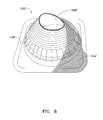
- FIG. 8is a top, perspective view of an alternative flashing for incorporation into my assembly.
- FIG. 9shows the installation procedure, step 1.
- FIG. 10shows the installation procedure, step 2.
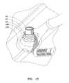
- FIG. 11shows the installation procedure, step 3.
- FIG. 12shows the installation procedure
- FIG. 13shows the installation procedure, step 5.
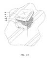
- FIG. 14shows the installation procedure, step 6.
- FIG. 15shows the installation procedure, step 7.
- shingles, vent pipe and corrugated metal roofare depicted in phantom outline as they form no part of the invention, and like numerals designate like component parts throughout the several views.
- a conventional vent hood 10is depicted installed over an opening 12 in a sloped roof 14 that is covered with asphalt shingles 16 overlying roof sheathing (not shown).
- the vent hood 10includes a generally planar, sheet metal base member 18 that rests atop shingles 16 that surround the roof opening 12 .
- the base member 18has a circular, central opening 20 that is disposed over the roof opening 12 and is coaxially aligned, more or less, with the vent pipe 30 .
- the vent hood 10further includes an upstanding, cylindrical collar 24 that surrounds and tightly engages an outer surface of the lip 22 .
- An annular flange 26extends radially outward at a circular, upper margin of the collar 24 .
- a mesh screen 28is attached to the flange 26 and entirely covers the upper, circular opening defined by the collar 24 .
- the vent hood 10further includes a yoke 40 , such as that depicted in FIG. 7 , which yoke surrounds and engages an upper, outer surface of the collar 24 .
- the yoke 40comprises four metal strips 40 a , 40 b , 40 c , and 40 d , joined end-to-end, each strip bent through one-quarter sector of a circle to form an overall ring shape.
- Each strip 40 a , 40 b , 40 c , 40 dhas a relatively long, first end 40 f bent radially outward, which forms a mounting tab, and said tab has a free end portion that is bent circumferentially and apertured, and an opposite, relatively short, second end 40 s that is bent radially outward and having a free end portion.
- the second ends 40 sare joined to the first ends 40 f by rivets (not shown), except for the first end 40 f of strip 40 b and the second end 40 s of the strip 40 a , which are attached by an adjustment screw 42 threaded through aligned apertures of said first and second ends.
- the vent hood 10still further includes a cover member 50 comprising a flat, rectangular top having four side margins 50 M.
- skirt 50 Scomprising parallel skirt panels 50 b and 50 c that attach by screws 54 inserted through apertures therein to the tabs 40 f of strips 40 b and 40 c , respectively, and parallel skirt panels 50 a and 50 d that attach by screws 54 inserted through apertures therein to the tabs 40 f of strips 40 a and 40 d , respectively.
- vent gases that rise through the vent pipe 30can escape upward through collar 24 and through the mesh screen 28 , and thence exit the vent hood 10 to the atmosphere through the space between the cover member 50 and the collar.
- the relatively flat upper surfaces of the asphalt shingles 16permit a weather tight seal with the base member 18 ; accordingly, a vent hood 10 of this kind can be successfully installed over asphalt shingles 16 and other relatively flat roof surface coverings.
- FIG. 3depicts a corrugated metal roof 60 overlying and attached to roof sheathing (not shown).
- vent hoods 10 of the kind depicted in FIGS. 1 and 2have been installed on such corrugated metal roofs, the results have been less than satisfactory as it has been difficult to adequately seal them against the weather.
- My vent hood and flashing assemblydenoted generally by the numeral 100 as depicted in FIG. 3 installed on a corrugated metal roof 60 , overcomes this problem as it facilitates creating a long-lasting, permanent seal with a corrugated metal roof.
- my assemblyincludes the combination of a flashing, denoted generally by the numeral 102 , with a vent hood, denoted generally by the numeral 104 .
- the flashing 102includes a flexible, resilient, water-repellant sleeve 106 , having an overall shape of a truncated cone and a central opening 108 , which sleeve is dimensioned to fit over, and surround, a vertical projection through a roof, such as a vent pipe 30 .
- the sleeve 106comprises a continuous array of concentric bands of elastomeric material 106 B, such as rubber, neoprene, or polyurethane, the diameters of which bands gradually diminish from a maximum diameter at a bottom margin 110 to a minimum diameter at a top margin 112 of the sleeve, which bottom margin is, in fact, an outer margin of an annular flange portion 114 of the sleeve that extends radially outward from a lower end portion of the sleeve.
- a plurality of concentric, circular grooves 116line a lower surface of the annular flange 114 for sealingly engaging a metal roof 60 .
- the ring seal 118preferably is fabricated from aluminum sheet that is sufficiently thin that the ring seal 118 , as well as the underlying, annular flange portion 114 of the sleeve 102 , can be bent to conform to the curved, upper surface of a corrugated metal roof 60 .
- the vent hood portion 104 of my assembly 100is generally similar to the vent hood 10 depicted in FIGS. 1 and 2 , but lacks the base member 18 thereof.
- the vent hood portion 104includes an upstanding, cylindrical collar 24 that is dimensioned for close fitting insertion into, and engagement with, an upper, interior portion of the sleeve 106 , whereby the upper portion of the sleeve is elastically expanded into a mating, cylindrical shape as well.
- the collar 24is preferably fabricated from steel sheet.
- the upper end portion of the sleeve 106 and the collar 24have each have four apertures (not shown) that are in register and spaced 90 degrees of arc apart about axis A-A, for receiving four screws 122 that secure the sleeve 106 to the collar 24 .
- Exemplary dimensions for the collar 24are, for instance, 7.5 inches inner diameter and height 3 inches, more or less.
- An annular flange 26extends radially outward at a circular, upper margin of the collar 24 , and a mesh screen 28 is attached to the flange 26 and entirely covers the upper, circular opening defined by the collar 24 .
- a suitable radial width for the annular flange 26is one-eighth to one-half inch.
- the mesh screen 28is dimensioned to exclude rodents and other pests from entering the flashing 102 .
- the vent hood 104further includes a yoke 40 , such as that depicted in FIG. 7 , which yoke surrounds and engages an upper, outer surface of the upper, cylindrical portion 106 U of the sleeve 106 and, consequently, surrounds the underlying collar 24 as well.
- the yoke 40comprises four metal strips 40 a , 40 b , 40 c , and 40 d , joined end-to-end, each strip bent through one-quarter sector of a circle to form an overall ring shape.
- Each strip 40 a , 40 b , 40 c , 40 dhas a relatively long, first end 40 f bent radially outward, which forms a mounting tab, and said tab has a free end portion that is bent circumferentially and apertured, and an opposite, relatively short, second end 40 s that is bent radially outward and having a free end portion.
- the second ends 40 sare joined to the first ends 40 f by rivets (not shown), except for the first end 40 f of strip 40 b and the second end 40 s of the strip 40 a , which are attached by an adjustment screw 42 threaded through aligned apertures of said first and second ends.
- the vent hood 104still further includes a cover member 50 comprising a flat, rectangular top having four side margins 50 M. From the four side margins 50 M depends a skirt 50 S comprising parallel skirt panels 50 b and 50 c that attach by screws 54 inserted through apertures therein to the tabs 40 f of strips 40 b and 40 c , respectively, and parallel skirt panels 50 a and 50 d that attach by screws 54 inserted through apertures therein to the tabs 40 f of strips 40 a and 40 d , respectively.
- the cover member 50With the cover member 50 thus attached by the yoke 40 to the collar 24 by tightening adjustment screw 42 , the cover member overlies the mesh screen 28 in vertically spaced relation, and the mesh screen overlies an upper end of the vent pipe 30 . Accordingly, vent gases that rise through the vent pipe 30 can escape upward through collar 24 and through the mesh screen 28 , and thence exit the vent hood 10 to the atmosphere through the space between the cover member 50 and the collar.
- Isubstitute for the above-described flashing portion 102 a second, alternative flashing portion 102 ′, as depicted in FIG. 8 , which is substantially identical to the flashing portion 102 depicted in FIG. 6 except that the flange 114 ′ thereof has a rectilinear periphery instead of annular shape and the mating, overlying ring seal 118 ′ is also rectilinear.
- This alternative embodiment 102 ′ of my assemblyis otherwise identical to that described above.
- my assembly 100is placed over a corrugated, metal roof opening 12 through which extends a through-the-roof-vent pipe 30 , the upper end of the pipe resting against or near the screen 28 and with the flange portion 118 or 118 ′ resting on the corrugated metal roof 60 that surrounds said opening.
- the installation procedureis depicted in FIGS. 9-15 .
- an upper end portion 102 U of the flashing 102is cut away with scissors 130 to leave an upper opening therein that is approximately 20% smaller than the diameter of the collar 24 .
- FIG. 9the first step
- the collar 24is inserted into, and attached by screws 54 , to the central opening 108 of the sleeve 106 at an upper end portion 102 U of the flashing 102 .
- the flashing 102 and attached collar 24are then slid down around the pipe 30 , using water to lubricate if necessary.
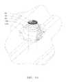
- the ring seal 118 and underlying flange 114are bent to conform to fit the curved surface of the roof 60 .
- the flashing 102is sealed by applying urethane/silicone sealant between the flange 114 and the surface of the roof 60 .
- FIG. 12the fifth step
- the sealis completed by fastening the ring seal 118 to the roof with weather-resistant fasteners.
- the mesh screen 28is placed over the collar 24 , its periphery is tamped down around the annular flange 26 at an upper end portion 102 U of the sleeve 102 ; then the yoke 40 is mounted around the screen 28 and collar 24 by tightening adjustment screw 42 .
- the cover 50is attached to the yoke 40 by screws 54 .
- my assembly 100may include a variety of means for attaching an upper end portion of the flashing 102 , 102 ′ to the vent hood 104 , such as by metal or plastic brackets that join the vent hood 104 and flashing 102 together such that the cover member 50 and the screen 28 are in fixed, vertically spaced-apart relation. Any suitable fasteners may be substituted for screws 54 and screws 122 as well.
Landscapes
- Engineering & Computer Science (AREA)
- Mechanical Engineering (AREA)
- General Engineering & Computer Science (AREA)
- Chemical & Material Sciences (AREA)
- Combustion & Propulsion (AREA)
- Architecture (AREA)
- Civil Engineering (AREA)
- Structural Engineering (AREA)
- Building Environments (AREA)
Abstract
Description
Claims (11)
Priority Applications (1)
| Application Number | Priority Date | Filing Date | Title |
|---|---|---|---|
| US12/799,660US8209923B1 (en) | 2010-04-28 | 2010-04-28 | Vent hood and flashing assembly for metal roof |
Applications Claiming Priority (1)
| Application Number | Priority Date | Filing Date | Title |
|---|---|---|---|
| US12/799,660US8209923B1 (en) | 2010-04-28 | 2010-04-28 | Vent hood and flashing assembly for metal roof |
Publications (1)
| Publication Number | Publication Date |
|---|---|
| US8209923B1true US8209923B1 (en) | 2012-07-03 |
Family
ID=46320024
Family Applications (1)
| Application Number | Title | Priority Date | Filing Date |
|---|---|---|---|
| US12/799,660Active - Reinstated2030-12-30US8209923B1 (en) | 2010-04-28 | 2010-04-28 | Vent hood and flashing assembly for metal roof |
Country Status (1)
| Country | Link |
|---|---|
| US (1) | US8209923B1 (en) |
Cited By (34)
| Publication number | Priority date | Publication date | Assignee | Title |
|---|---|---|---|---|
| US20120073221A1 (en)* | 2009-04-15 | 2012-03-29 | Sk Tuote Oy | Device for leading pipes of a solar cell through a roof |
| US20120073239A1 (en)* | 2010-09-23 | 2012-03-29 | Haines Jacob L | Flexible-Based Roof Vent for Metal Roofing |
| US20130115871A1 (en)* | 2011-11-07 | 2013-05-09 | Antoine Bourque | Snow Proof Roof Vent |
| US20140194053A1 (en)* | 2013-01-04 | 2014-07-10 | Fleming Vaughn Carroll | Vertical Vent Stack Cap |
| CN104074319A (en)* | 2014-05-21 | 2014-10-01 | 浙江电联通信机房工程技术有限公司 | Colored steel flat plate roof perforated waterproof component |
| US20160053499A1 (en)* | 2014-08-21 | 2016-02-25 | Solarcity Corporation | Exhaust gas panel vent assembly for roof-mounted photovoltaic systems |
| US20160169543A1 (en)* | 2014-12-10 | 2016-06-16 | Roger Allestad | System for ventilating a structure |
| USD762835S1 (en)* | 2012-05-16 | 2016-08-02 | Roy R. Stocker | Fan with a solar panel |
| USD773629S1 (en)* | 2014-04-04 | 2016-12-06 | Elica S.P.A. | Extractor fan |
| US9534392B2 (en) | 2014-02-24 | 2017-01-03 | Liberty Diversified International, Inc. | Telescoping pipe boot |
| US9581271B2 (en) | 2013-08-23 | 2017-02-28 | Lake Products Limited | Sealing gland |
| US20170059061A1 (en)* | 2015-08-24 | 2017-03-02 | Lake Products Limited | Sealing gland |
| USD783144S1 (en) | 2014-11-18 | 2017-04-04 | Jonathan P. Leonard | Roof vent sleeve with round base |
| USD785768S1 (en) | 2012-09-21 | 2017-05-02 | Lake Products Limited | Sealing gland |
| US20170122609A1 (en)* | 2015-11-04 | 2017-05-04 | Canplas Industries Ltd. | Flapper valve adaptor for a roof vent and method of installing the same |
| USD796013S1 (en) | 2005-10-27 | 2017-08-29 | Lake Products Limited | Sealing gland |
| USD796014S1 (en)* | 2006-05-18 | 2017-08-29 | Lake Products Limited | Sealing gland |
| USD798472S1 (en)* | 2015-07-28 | 2017-09-26 | JT Roofing Pty Ltd | Roofing flashing |
| US9879430B2 (en) | 2014-10-10 | 2018-01-30 | Solarcity Corporation | Replacement flashing for exhaust gas vents beneath roof-mounted photovoltaic systems |
| WO2018075677A1 (en)* | 2016-10-21 | 2018-04-26 | Aztec Manufacturing, Inc. | Roof vent adaptors and methods |
| USD840516S1 (en) | 2006-09-11 | 2019-02-12 | Lake Products Limited | Sealing gland |
| US10295208B2 (en) | 2011-11-07 | 2019-05-21 | Snowventco Limited | Roof vent |
| USD850653S1 (en)* | 2017-04-07 | 2019-06-04 | Suncast Technologies Llc | Vented skylight |
| US10852016B2 (en) | 2011-11-07 | 2020-12-01 | Snowventco Limited | Roof vent |
| US10989437B1 (en) | 2014-06-13 | 2021-04-27 | John T. Dolan | Insect barriers for inlets and vents |
| US11181297B2 (en)* | 2020-10-29 | 2021-11-23 | Khosrow Anthony Afkhampour | Vent assembly for a ventilation system |
| US20220275636A1 (en)* | 2019-11-18 | 2022-09-01 | Mark Gilstrap | Width-selectable pipe flashing piece and method of use |
| US11448344B2 (en)* | 2019-11-18 | 2022-09-20 | Mark Gilstrap | Width-selectable pipe flashing piece and method of use |
| US11585545B2 (en) | 2011-11-07 | 2023-02-21 | Snowventco Limited | Ridge vent |
| US20230112254A1 (en)* | 2021-10-07 | 2023-04-13 | William Roger AYERS | Structure inspection and access device |
| US11788744B2 (en) | 2012-05-16 | 2023-10-17 | Solar Royal, LLC | Ventilation systems |
| EP4070012A4 (en)* | 2019-11-07 | 2024-02-07 | McDow, William Archie Jr. | Roof vent with secure attachment mechanisms |
| USD1050364S1 (en)* | 2022-06-03 | 2024-11-05 | The Drain Guardian, Llc | Pipe cap for drain pipe outlet |
| USRE50321E1 (en)* | 2017-04-26 | 2025-03-04 | Container Creations LLC | Shipping container adapter |
Citations (15)
| Publication number | Priority date | Publication date | Assignee | Title |
|---|---|---|---|---|
| US1686881A (en)* | 1927-03-17 | 1928-10-09 | Robert J Stephenson | Roof flashing |
| US2825276A (en)* | 1956-10-25 | 1958-03-04 | Porter Co | Pipeline vent cap and arrangement |
| US3398671A (en)* | 1966-10-18 | 1968-08-27 | W A Call Mfg Inc | Roof ventilator with u-shaped flue cap |
| US3886852A (en)* | 1972-12-18 | 1975-06-03 | Salvador J Acosta | Roof jack structure |
| US4333660A (en)* | 1977-01-17 | 1982-06-08 | Cupit George M | Seal device for pipe projecting through roof |
| US4437687A (en)* | 1980-11-24 | 1984-03-20 | Wilson James H | Waterproof assembly or sealing an aperture housing a conduit |
| US4664390A (en)* | 1984-04-04 | 1987-05-12 | John Deks Australia Pty. Ltd. | Weather seal device for conduit extending through ridged surface |
| US5176408A (en)* | 1987-06-04 | 1993-01-05 | Pedersen Raymond J | Seal device for pipes passing through roof structures |
| US5226263A (en) | 1991-08-22 | 1993-07-13 | Wil-Mar Products, Inc. | Weather-tight roof flashing shield |
| US5402611A (en)* | 1993-04-12 | 1995-04-04 | Vagedes; Michael | Roof vent |
| US20030054754A1 (en) | 2001-09-20 | 2003-03-20 | Canplas Industries Ltd. | Passive venting device |
| US20030104779A1 (en) | 2001-11-30 | 2003-06-05 | Marts Steven T. | Security cover for ventilation duct |
| US20040255523A1 (en)* | 2004-03-08 | 2004-12-23 | Andre Bibaud | Flashing for inclined roof and method for installing the same |
| US20050055889A1 (en) | 2003-09-03 | 2005-03-17 | Ken Thaler | Roof flashing assembly |
| US6954947B1 (en) | 2004-04-27 | 2005-10-18 | Williams Jr Marvin J | Pluming vent cover |
- 2010
- 2010-04-28USUS12/799,660patent/US8209923B1/enactiveActive - Reinstated
Patent Citations (16)
| Publication number | Priority date | Publication date | Assignee | Title |
|---|---|---|---|---|
| US1686881A (en)* | 1927-03-17 | 1928-10-09 | Robert J Stephenson | Roof flashing |
| US2825276A (en)* | 1956-10-25 | 1958-03-04 | Porter Co | Pipeline vent cap and arrangement |
| US3398671A (en)* | 1966-10-18 | 1968-08-27 | W A Call Mfg Inc | Roof ventilator with u-shaped flue cap |
| US3886852A (en)* | 1972-12-18 | 1975-06-03 | Salvador J Acosta | Roof jack structure |
| US4333660A (en)* | 1977-01-17 | 1982-06-08 | Cupit George M | Seal device for pipe projecting through roof |
| US4437687A (en)* | 1980-11-24 | 1984-03-20 | Wilson James H | Waterproof assembly or sealing an aperture housing a conduit |
| US4664390A (en)* | 1984-04-04 | 1987-05-12 | John Deks Australia Pty. Ltd. | Weather seal device for conduit extending through ridged surface |
| US5176408A (en)* | 1987-06-04 | 1993-01-05 | Pedersen Raymond J | Seal device for pipes passing through roof structures |
| US5226263A (en) | 1991-08-22 | 1993-07-13 | Wil-Mar Products, Inc. | Weather-tight roof flashing shield |
| US5402611A (en)* | 1993-04-12 | 1995-04-04 | Vagedes; Michael | Roof vent |
| US20030054754A1 (en) | 2001-09-20 | 2003-03-20 | Canplas Industries Ltd. | Passive venting device |
| US20030104779A1 (en) | 2001-11-30 | 2003-06-05 | Marts Steven T. | Security cover for ventilation duct |
| US20050055889A1 (en) | 2003-09-03 | 2005-03-17 | Ken Thaler | Roof flashing assembly |
| US20040255523A1 (en)* | 2004-03-08 | 2004-12-23 | Andre Bibaud | Flashing for inclined roof and method for installing the same |
| US7114301B2 (en) | 2004-03-08 | 2006-10-03 | Compagnie De Cheminees Industrielles, Inc. | Flashing for inclined roof and method for installing the same |
| US6954947B1 (en) | 2004-04-27 | 2005-10-18 | Williams Jr Marvin J | Pluming vent cover |
Non-Patent Citations (3)
| Title |
|---|
| Advertisement for flashing displayed on Internet at http://www.westcoastwashersusaa.com/flasherspecs.htm. |
| PortalsPlus 4YN30 Flat Roof Flashing advertisement, displayed on Internet at http://www.amazon.com/dp/B000LDIAEO/ref=asc-df-et cetera. |
| PortalsPlus 4YN30 Flat Roof Flashing advertisement, displayed on Internet at http://www.amazon.com/dp/B000LDIAEO/ref=asc—df—et cetera. |
Cited By (55)
| Publication number | Priority date | Publication date | Assignee | Title |
|---|---|---|---|---|
| USD796013S1 (en) | 2005-10-27 | 2017-08-29 | Lake Products Limited | Sealing gland |
| US10822802B2 (en) | 2005-10-27 | 2020-11-03 | Lake Products Limited | Peripheral sealing gland for elongate objects passing through a surface or beyond a pipe end |
| US10526789B2 (en) | 2005-10-27 | 2020-01-07 | Lake Products Limited | Peripheral sealing gland for elongate objects passing through a surface or beyond a pipe end |
| US10081947B2 (en) | 2005-10-27 | 2018-09-25 | Lake Products Limited | Peripheral sealing gland for elongate objects passing through a surface or beyond a pipe end |
| US10000934B2 (en) | 2005-10-27 | 2018-06-19 | Lake Products Limited | Peripheral sealing gland for elongate objects passing through a surface or beyond a pipe end |
| USD958942S1 (en)* | 2006-05-18 | 2022-07-26 | Lake Products Limited | Sealing gland |
| USD958305S1 (en)* | 2006-05-18 | 2022-07-19 | Lake Products Limited | Sealing gland |
| USD796014S1 (en)* | 2006-05-18 | 2017-08-29 | Lake Products Limited | Sealing gland |
| USD840516S1 (en) | 2006-09-11 | 2019-02-12 | Lake Products Limited | Sealing gland |
| US8522497B2 (en)* | 2009-04-15 | 2013-09-03 | Sk Tuote Oy | Device for leading pipes of a solar cell through a roof |
| US20120073221A1 (en)* | 2009-04-15 | 2012-03-29 | Sk Tuote Oy | Device for leading pipes of a solar cell through a roof |
| US20120073239A1 (en)* | 2010-09-23 | 2012-03-29 | Haines Jacob L | Flexible-Based Roof Vent for Metal Roofing |
| US10852016B2 (en) | 2011-11-07 | 2020-12-01 | Snowventco Limited | Roof vent |
| US11585545B2 (en) | 2011-11-07 | 2023-02-21 | Snowventco Limited | Ridge vent |
| US10295208B2 (en) | 2011-11-07 | 2019-05-21 | Snowventco Limited | Roof vent |
| US20130115871A1 (en)* | 2011-11-07 | 2013-05-09 | Antoine Bourque | Snow Proof Roof Vent |
| US10018368B2 (en)* | 2011-11-07 | 2018-07-10 | Snowventco Ltd. | Snow proof roof vent |
| US11788744B2 (en) | 2012-05-16 | 2023-10-17 | Solar Royal, LLC | Ventilation systems |
| USD762835S1 (en)* | 2012-05-16 | 2016-08-02 | Roy R. Stocker | Fan with a solar panel |
| USD821553S1 (en) | 2012-09-21 | 2018-06-26 | Lake Products Limited | Sealing gland |
| USD785768S1 (en) | 2012-09-21 | 2017-05-02 | Lake Products Limited | Sealing gland |
| USD801487S1 (en) | 2012-09-21 | 2017-10-31 | Lake Products Limited | Sealing gland |
| US10711923B2 (en) | 2012-09-21 | 2020-07-14 | Lake Products Limited | Sealing gland |
| US20140194053A1 (en)* | 2013-01-04 | 2014-07-10 | Fleming Vaughn Carroll | Vertical Vent Stack Cap |
| US10663192B2 (en)* | 2013-01-04 | 2020-05-26 | Fleming Vaughn Carroll | Vertical vent stack cap |
| US9581271B2 (en) | 2013-08-23 | 2017-02-28 | Lake Products Limited | Sealing gland |
| US9534392B2 (en) | 2014-02-24 | 2017-01-03 | Liberty Diversified International, Inc. | Telescoping pipe boot |
| USD773629S1 (en)* | 2014-04-04 | 2016-12-06 | Elica S.P.A. | Extractor fan |
| CN104074319A (en)* | 2014-05-21 | 2014-10-01 | 浙江电联通信机房工程技术有限公司 | Colored steel flat plate roof perforated waterproof component |
| US10989437B1 (en) | 2014-06-13 | 2021-04-27 | John T. Dolan | Insect barriers for inlets and vents |
| US20160053499A1 (en)* | 2014-08-21 | 2016-02-25 | Solarcity Corporation | Exhaust gas panel vent assembly for roof-mounted photovoltaic systems |
| US9869095B2 (en)* | 2014-08-21 | 2018-01-16 | Solarcity Corporation | Exhaust gas panel vent assembly for roof-mounted photovoltaic systems |
| US10323418B2 (en) | 2014-10-10 | 2019-06-18 | Solarcity Corporation | Vent cover assembly for use with roof-mounted photovoltaic systems |
| US9879430B2 (en) | 2014-10-10 | 2018-01-30 | Solarcity Corporation | Replacement flashing for exhaust gas vents beneath roof-mounted photovoltaic systems |
| USD783144S1 (en) | 2014-11-18 | 2017-04-04 | Jonathan P. Leonard | Roof vent sleeve with round base |
| US20160169543A1 (en)* | 2014-12-10 | 2016-06-16 | Roger Allestad | System for ventilating a structure |
| USD798472S1 (en)* | 2015-07-28 | 2017-09-26 | JT Roofing Pty Ltd | Roofing flashing |
| US20170059061A1 (en)* | 2015-08-24 | 2017-03-02 | Lake Products Limited | Sealing gland |
| US9951890B2 (en)* | 2015-08-24 | 2018-04-24 | Lake Products Limited | Sealing gland |
| US20170122609A1 (en)* | 2015-11-04 | 2017-05-04 | Canplas Industries Ltd. | Flapper valve adaptor for a roof vent and method of installing the same |
| US10180260B2 (en)* | 2015-11-04 | 2019-01-15 | Canplas Industries Ltd. | Flapper valve adaptor for a roof vent and method of installing the same |
| US10161135B2 (en) | 2016-10-21 | 2018-12-25 | Aztec Manufacturing, Inc. | Roof vent adaptors and methods |
| US10604938B2 (en) | 2016-10-21 | 2020-03-31 | Aztec Manufacturing, Inc. | Roof vent adaptors and methods |
| WO2018075677A1 (en)* | 2016-10-21 | 2018-04-26 | Aztec Manufacturing, Inc. | Roof vent adaptors and methods |
| US11274449B2 (en) | 2016-10-21 | 2022-03-15 | Aztec Manufacturing, Inc. | Roof vent adaptors and methods |
| USD850653S1 (en)* | 2017-04-07 | 2019-06-04 | Suncast Technologies Llc | Vented skylight |
| USRE50321E1 (en)* | 2017-04-26 | 2025-03-04 | Container Creations LLC | Shipping container adapter |
| EP4070012A4 (en)* | 2019-11-07 | 2024-02-07 | McDow, William Archie Jr. | Roof vent with secure attachment mechanisms |
| US20220275636A1 (en)* | 2019-11-18 | 2022-09-01 | Mark Gilstrap | Width-selectable pipe flashing piece and method of use |
| US11448344B2 (en)* | 2019-11-18 | 2022-09-20 | Mark Gilstrap | Width-selectable pipe flashing piece and method of use |
| US12152383B2 (en)* | 2019-11-18 | 2024-11-26 | Mark Gilstrap | Width-selectable pipe flashing piece and method of use |
| US11181297B2 (en)* | 2020-10-29 | 2021-11-23 | Khosrow Anthony Afkhampour | Vent assembly for a ventilation system |
| US20230112254A1 (en)* | 2021-10-07 | 2023-04-13 | William Roger AYERS | Structure inspection and access device |
| US11795706B2 (en)* | 2021-10-07 | 2023-10-24 | William Roger AYERS | Structure inspection and access device |
| USD1050364S1 (en)* | 2022-06-03 | 2024-11-05 | The Drain Guardian, Llc | Pipe cap for drain pipe outlet |
Similar Documents
| Publication | Publication Date | Title |
|---|---|---|
| US8209923B1 (en) | Vent hood and flashing assembly for metal roof | |
| US6185885B1 (en) | Roof flashing assembly | |
| US5328212A (en) | Interiorly installable roof mount | |
| US6279272B1 (en) | Full coverage vent pipe flashing | |
| US20120073239A1 (en) | Flexible-Based Roof Vent for Metal Roofing | |
| US5435780A (en) | Ventilated skylight | |
| US4010578A (en) | Roof flashing structure | |
| US5394663A (en) | Pipe flashing vent | |
| US7901278B2 (en) | Hybrid metal-plastic roof vent | |
| US7775005B2 (en) | Vent pipe covering system | |
| US8650833B1 (en) | Method for installing a roof vent | |
| US7040061B2 (en) | Tubular skylight with dome flashing and protective corrugation | |
| US20140167405A1 (en) | Insert for HVAC Systems | |
| US20190249439A1 (en) | Vent and flashing system | |
| US20250137267A1 (en) | Roof vent with contoured foot | |
| US20090023377A1 (en) | Vent system insert apparatus and method for installation | |
| US10415252B1 (en) | Attic vent | |
| US11649635B2 (en) | Roof vent with secure attachment mechanisms | |
| US6296560B1 (en) | Chimney cap assembly | |
| US6431972B1 (en) | Multiple plumbing vent apparatus | |
| US6997801B1 (en) | Roofing vent with sliding collar | |
| CA3093094C (en) | Flue cap cover | |
| JP3090951U (en) | Drain port member | |
| DK179199B9 (en) | Pipe Flashing | |
| AU2019201255A1 (en) | Cover for a vent pipe |
Legal Events
| Date | Code | Title | Description |
|---|---|---|---|
| ZAAA | Notice of allowance and fees due | Free format text:ORIGINAL CODE: NOA | |
| ZAAB | Notice of allowance mailed | Free format text:ORIGINAL CODE: MN/=. | |
| STCF | Information on status: patent grant | Free format text:PATENTED CASE | |
| REMI | Maintenance fee reminder mailed | ||
| FPAY | Fee payment | Year of fee payment:4 | |
| SULP | Surcharge for late payment | ||
| FEPP | Fee payment procedure | Free format text:PAYOR NUMBER ASSIGNED (ORIGINAL EVENT CODE: ASPN); ENTITY STATUS OF PATENT OWNER: SMALL ENTITY | |
| FEPP | Fee payment procedure | Free format text:MAINTENANCE FEE REMINDER MAILED (ORIGINAL EVENT CODE: REM.); ENTITY STATUS OF PATENT OWNER: SMALL ENTITY | |
| FEPP | Fee payment procedure | Free format text:7.5 YR SURCHARGE - LATE PMT W/IN 6 MO, SMALL ENTITY (ORIGINAL EVENT CODE: M2555); ENTITY STATUS OF PATENT OWNER: SMALL ENTITY | |
| MAFP | Maintenance fee payment | Free format text:PAYMENT OF MAINTENANCE FEE, 8TH YR, SMALL ENTITY (ORIGINAL EVENT CODE: M2552); ENTITY STATUS OF PATENT OWNER: SMALL ENTITY Year of fee payment:8 | |
| FEPP | Fee payment procedure | Free format text:MAINTENANCE FEE REMINDER MAILED (ORIGINAL EVENT CODE: REM.); ENTITY STATUS OF PATENT OWNER: SMALL ENTITY | |
| LAPS | Lapse for failure to pay maintenance fees | Free format text:PATENT EXPIRED FOR FAILURE TO PAY MAINTENANCE FEES (ORIGINAL EVENT CODE: EXP.); ENTITY STATUS OF PATENT OWNER: SMALL ENTITY | |
| STCH | Information on status: patent discontinuation | Free format text:PATENT EXPIRED DUE TO NONPAYMENT OF MAINTENANCE FEES UNDER 37 CFR 1.362 | |
| FP | Lapsed due to failure to pay maintenance fee | Effective date:20240703 | |
| PRDP | Patent reinstated due to the acceptance of a late maintenance fee | Effective date:20240919 | |
| FEPP | Fee payment procedure | Free format text:PETITION RELATED TO MAINTENANCE FEES FILED (ORIGINAL EVENT CODE: PMFP); ENTITY STATUS OF PATENT OWNER: SMALL ENTITY Free format text:PETITION RELATED TO MAINTENANCE FEES GRANTED (ORIGINAL EVENT CODE: PMFG); ENTITY STATUS OF PATENT OWNER: SMALL ENTITY Free format text:SURCHARGE, PETITION TO ACCEPT PYMT AFTER EXP, UNINTENTIONAL. (ORIGINAL EVENT CODE: M2558); ENTITY STATUS OF PATENT OWNER: SMALL ENTITY | |
| MAFP | Maintenance fee payment | Free format text:PAYMENT OF MAINTENANCE FEE, 12TH YR, SMALL ENTITY (ORIGINAL EVENT CODE: M2553); ENTITY STATUS OF PATENT OWNER: SMALL ENTITY Year of fee payment:12 | |
| STCF | Information on status: patent grant | Free format text:PATENTED CASE |