US8209121B1 - Registration of location data to street maps using hidden markov models, and application thereof - Google Patents
Registration of location data to street maps using hidden markov models, and application thereofDownload PDFInfo
- Publication number
- US8209121B1 US8209121B1US11/870,265US87026507AUS8209121B1US 8209121 B1US8209121 B1US 8209121B1US 87026507 AUS87026507 AUS 87026507AUS 8209121 B1US8209121 B1US 8209121B1
- Authority
- US
- United States
- Prior art keywords
- polyline
- location
- probability
- sequence
- features
- Prior art date
- Legal status (The legal status is an assumption and is not a legal conclusion. Google has not performed a legal analysis and makes no representation as to the accuracy of the status listed.)
- Active, expires
Links
Images


Classifications
- G—PHYSICS
- G01—MEASURING; TESTING
- G01C—MEASURING DISTANCES, LEVELS OR BEARINGS; SURVEYING; NAVIGATION; GYROSCOPIC INSTRUMENTS; PHOTOGRAMMETRY OR VIDEOGRAMMETRY
- G01C21/00—Navigation; Navigational instruments not provided for in groups G01C1/00 - G01C19/00
- G01C21/26—Navigation; Navigational instruments not provided for in groups G01C1/00 - G01C19/00 specially adapted for navigation in a road network
- G01C21/28—Navigation; Navigational instruments not provided for in groups G01C1/00 - G01C19/00 specially adapted for navigation in a road network with correlation of data from several navigational instruments
- G01C21/30—Map- or contour-matching
Definitions
- GPS devicesgenerate location data.
- the generated location datae.g., latitude and longitude values
- Particle filtering and Kalman filteringhave both been used in an attempt to improve the accuracy of GPS location data. While these filtering techniques can be advantageous, both techniques have limitations. For example, both particle filtering and Kalman filtering do not give globally optimal solutions. Furthermore, both particle filtering and Kalman filtering typically require significant computing resources such as memory and processing time. Accordingly, there is a current need for new devices and techniques that overcome these and other deficiencies.
- a systemincludes a spatial indexer, an emission probability calculator, a transition probability calculator, and a pose optimizer.
- the spatial indexerreceives a sequence of location data corresponding to a plurality of locations. For each location, the spatial indexer identifies in a map database polyline features within a distance D from the location.
- the emission probability calculatorcalculates emission probabilities for the polyline features identified by the spatial indexer. Each emission probability E ij represents the probability that a street on the map represented by a polyline feature P j emitted the observed location C i .
- the transition probability calculatorcalculates transition probabilities for the polyline features identified by the spatial indexer.
- Each transition probability T xyrepresents the probability of a transition from a polyline feature P x to a polyline feature P y .
- the pose optimizeradjusts the location data for the plurality of locations so that the adjusted location data correspond to polyline features belonging to a sequence of polyline features selected based on the emission probabilities calculated by the emission probability calculator and the transition probabilities calculated by the transition probability calculator.
- the present inventionadjusts coordinates obtained using a satellite-based positioning device by (1) receiving a sequence of coordinates corresponding to a plurality of locations; (2) identifying in a map database, for each location, polyline features within a certain distance from the coordinates for the location; (3) calculating emission probabilities for the polyline features; (4) calculating transition probabilities for the polyline features; and (5) adjusting the coordinates for the plurality of locations so that the adjusted coordinates correspond to polyline features belonging to a sequence of polyline features selected based on the emission probabilities and the transition probabilities.
- GPS locations to street locations on a mapenables novel geospatial applications and user interfaces by adding a large amount of meta-information to a location, such as the street address, navigation information (connected streets and intersections), nearby business information, etc.
- FIG. 1is a diagram that illustrates an example street map with a sequence of location data adjusted to a location of polyline features on a map.
- FIG. 2is a diagram that illustrates a system according to an embodiment of the present invention that adjusts a sequence of location data to the location of polyline features on a map and that displays the adjusted data to a user.
- FIG. 3is a diagram that illustrates the system of FIG. 2 in more detail.
- FIG. 4is a flowchart that illustrates a method for adjusting location data to the location of polyline features on a map according to an embodiment of the present invention.
- FIGS. 5A and 5Bare diagrams that illustrate an example of how features are recalled for a particular location according to an embodiment of the present invention.
- FIG. 6Ais a diagram that illustrates an example of how transition probabilities are calculated according to an embodiment of the present invention.
- FIG. 6Bis a diagram that illustrates an example of how emission probabilities are calculated according to an embodiment of the present invention.
- FIG. 6Cis a diagram that illustrates an example of how location data is snapped to points on a street according to an embodiment of the present invention.
- the present inventionprovides systems and methods for improving the accuracy of location data generated, for example, using a satellite-based positioning device, and applications thereof. While the present invention is described herein with reference to illustrative embodiments for particular applications, it should be understood that the invention is not limited thereto. Those skilled in the art with access to the teachings provided herein will recognize additional modifications, applications, and embodiments within the scope thereof and additional fields in which the invention would be of significant utility.
- FIG. 1is a diagram that illustrates an example street map 100 .
- streetssuch as street 104 are represented by polyline features.
- Each polyline featureincludes information such as, for example, geometry information, a street name, an address, turn restrictions, number of street lanes, intersection information, identification of other polyline features to which it connects, etc.
- FIG. 1also illustrates how a sequence of location data 106 (e.g., generated using a satellite-based positioning device carried in a vehicle) is adjusted to form a sequence of adjusted location data 108 that corresponds to a set of polyline features used to represent street 104 of map 100 .
- both the sequence of location data 106 and the sequence of adjusted location data 108are represented by solid lines.
- the sequence of location data and the sequence of adjusted location datacan be sequences of non-continuous locations (e.g., non-continuous coordinates and headings).
- Such non-continuous locationsare represented by locations 110 A- 110 N and adjusted locations 112 A- 112 N.
- each location 110 A- 110 Nincludes both coordinate and heading information.
- the coordinate informationcan be, for example, latitude and longitude information.
- the location datacan be generated using a satellite-based positioning system device, such as a GPS receiver, carried in a vehicle.
- the inventionis not limited, however, to using just a GPS receiver.
- the location datacan be generated using other devices and/or sensors such as a vehicle wheel encoder.
- a vehicle wheel encoderestimates where a vehicle is located based on wheel movements. Using the present invention, it is possible to improve the accuracy of noisy measurements obtained using such devices and/or sensors and to correctly snap location data obtained using these devices and/or sensors to a street.
- the sequence of location data 106(e.g., locations 110 A- 110 N) is adjusted to form the sequence of adjusted location data 108 (e.g., adjusted locations 112 A- 112 N).
- the sequence of adjusted location data 108corresponds to the set of polyline features that represent street 104 in map 100 .
- each adjusted location 112 A- 112 Ncorresponds to a coordinate that lies along street 104 and has a heading corresponding to that associated with street 104 .
- Kalman and particle filteringsnap location data on a point-by-point basis. For example, Kalman and particle filtering would snap a point (e.g., location 110 A) to a new point (e.g., location 112 A) without necessarily using information from all the other points (e.g., locations 110 B-N) optimally.
- Embodiments of the present inventionhowever, optimally snap entire sequences of locations to sequences of polyline features that represent a street. These embodiments take advantage, for example, of the connectivity and heading information about the street.
- these embodimentstake into consideration that a GPS receiver carried in a vehicle can not easily move from one street to another, unless the streets are connected. Taking into consideration this additional information enables embodiments of the present invention to adjust/snap correctly sequences of location data.
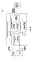
- FIG. 2is a diagram of a system 200 according to an embodiment of the present invention.
- System 200can adjust a sequence of location data to the location of polyline features on a map and display the adjusted data to a user.
- system 200includes a GPS track database 202 , a map database 204 , a processing pipeline server 210 , and a street track database 220 .
- Data stored in street track database 220is viewed, for example, using a street track server 230 and a street track client 250 that communicates with street track server 230 over a network 240 or using a viewer 260 coupled to street track database 220 .
- Each of the elements shown in FIG. 2can be any type of computing device.
- Example computing devicesinclude, but are not limited to, a computer, a workstation, a distributed computing system, an embedded system, a stand-alone electronic device, a networked device, a mobile device, a rack server, a portable GPS device, a television, etc.
- GPS track database 202stores sequences of location data.
- the sequences of location datacan be collected, e.g., using vehicles with GPS receivers and/or other sensors.
- Each location in a sequence of location datacan include a coordinate and a heading.
- Each coordinatecan include, for example, a latitude and a longitude.
- Map database 204stores information for one or more maps. These map(s) includes polyline features that represent, for example, a portion of a road, an intersection, an overpass, a bridge, a tunnel, etc. Each polyline feature typically has a unique identifier called a feature ID.
- map database 204includes a feature index.
- the feature indexmaps the feature ID of a polyline feature to feature data.
- feature datacan include a road name, road geometry, road connectivity, whether the road is one-way or two-way, turn restrictions (e.g., no U-turns allowed), etc.
- Intersection featurescan contain feature IDs of roads terminating at the intersection. In this way, the feature index maintains, for example, information on the connectivity of the features.
- each polyline featureis accessible using a spatial index.
- a spatial indexorganizes polyline features into geographic areas called bins.
- binshave a standard size (e.g., 50 meters by 50 meters), and each bin has a unique geographic ID (e.g., an s2cellID). Bins contain a list of feature IDs that lie within their associated geographical areas.
- Processing pipeline server 210processes data from the GPS track database, map database and possibly other databases (not shown).
- processing pipeline server 210receives a sequence of location data from GPS track database 202 .
- Processing pipeline server 210adjusts the location data to correspond with polyline features in map database 204 .
- Processing pipeline server 210writes the sequence of adjusted location data to street track database 220 .
- Street track database 220stores the sequence of adjusted location data.
- processing pipeline server 210snaps sequences of location data, as opposed to snapping individual locations. This allows processing pipeline server 210 , for example, to take into consideration knowledge of the continuity of polyline features such as streets and to correctly snap sequences of location data.
- Processing pipeline server 210contains a spatial indexer 212 and a pose optimizer 214 .
- Spatial indexer 212 and pose optimizer 214can be implemented as hardware, software, firmware or any combination thereof.
- Spatial indexer 212looks up features corresponding to particular locations from GPS track database 220 .
- Spatial indexer 212gathers polyline features surrounding a location. For each polyline feature surrounding a location, spatial indexer 212 calculates the distance between the location and the polyline feature.
- spatial indexer 212also calculates a heading differential between the location and the polyline feature. The operation of spatial indexer 212 is described in more detail below.
- Spatial indexer 212sends its information to pose optimizer 214 .
- Pose optimizer 214adjusts and/or snaps each location for a sequence of location data to correspond to a location of a polyline feature stored in map database 204 .
- Pose optimizer 214uses surrounding polyline features and distances determined by spatial indexer 212 to adjust a sequence of location data. In an embodiment, pose optimizer 214 accomplishes this by treating the adjusted points as hidden states in a hidden Markov model.
- Pose optimizer 214uses the Viterbi algorithm to decode the sequence of adjusted location data. The operation of pose optimizer 214 is described in more detail below.
- Processing pipeline server 210outputs sequences of adjusted location data determined by pose optimizer 214 to street track database 220 .
- street track database 220stores information such as image panoramas that correspond to locations in sequences of adjusted location data.
- street track database 220is viewed using street track server 230 and a street track client 250 that communicates with street track server 230 over a network 240 .
- street track client 250includes a web browser that is used to view the data.
- the web browsercan display, for example, an adjusted location data sequence as a line overlaying a map. When a user selects a point on a line, a photographic image taken from that location can be displayed. This example is merely illustrative and is not meant to limit the present invention.
- street track client 250communicates with street track server 230 over a network 240 or a group of networks that together comprise the network 240 illustrated in FIG. 2 .
- Network 240can be any network or combination of networks that facilitate data communication.
- network 240can include, but is not limited to, a local area network, a medium area network, and/or a wide area network such as the Internet.
- Network 240can support protocols and technology including, but not limited to, World Wide Web protocols and/or services.
- Intermediate web servers, gateways, or other serversmay be provided between street track server 230 and street track client 250 .
- Street track client 250may request adjusted location data sequence from street track server 230 .
- Street track server 230retrieves adjusted location data from street track database 220 .
- Street track server 230formats the adjusted location data, and as an example, street track server 230 may overlay the adjusted location data on a map.
- Street track server 230may include a web server.
- a web serveris a software component that responds to a hypertext transfer protocol (HTTP) request with an HTTP reply.
- the web servermay be, without limitation, an Apache HTTP Server, an Apache Tomcat, a Microsoft Internet Information Server, a JBoss Application Server, a WebLogic Application Server, or a Sun Java System Web Server.
- the web servermay serve content such as hypertext markup language (HTML), extendable markup language (XML), documents, videos, images, multimedia features, or any combination thereof. This example is strictly illustrative and does not limit the present invention.
- FIG. 3is a diagram that illustrates various elements of system 200 in more detail.
- spatial indexer 212includes a feature finder 312 and a distance calculator 314 .
- Pose optimizer 214includes, in an embodiment, an emission probability calculator 322 , a transition probability calculator 324 , a prior probability calculator 328 , and a Viterbi decoder 326 .
- spatial indexer 212receives a sequence of location data 302 from GPS street track database 202 .
- Sequence of location data 302may be collected, for example, by one or more vehicles with GPS receivers and/or other sensors (e.g., wheel encoders).
- Each location in the sequence of location datacan include coordinate and/or heading values.
- each location in sequence of location data 302may be collected at regular time and/or distance intervals.
- the sequence of location data 302may be received in real-time or near real-time. This means that the most recently collected location data in the sequence of location data was received by spatial indexer 212 soon after it was collected.
- feature finder 312 of spatial indexer 212identifies polyline features within a radius R stored in map database 204 .
- the radius Rshould be large enough to cover all possible polyline features to which the location could map. Therefore, the radius R should be larger, for example, than the error range, at a particular confidence interval, of the GPS receiver used to determine the location.
- feature finder 312identifies features by recalling the s2cellID for each bin within radius R. Feature finder 312 uses the spatial index to get a list of all polyline features and corresponding feature information associated with bins within radius R. As shown in FIG. 3 , the retrieved polyline features are identified as map features 308 . Map features 308 include, for example, information such as geometry information, street name information, address information, turn restriction information, connectivity information, etc.
- the binsmay cover more area than the circle of radius R.
- polyline featuresmay be recalled from map a database 204 that are outside the area of interest (e.g., the circle of radius R).
- feature finder 312includes logic that selects only features that lie within the area of interest. An example of this is described below.
- distance calculator 314calculates a distance between each location and each feature within radius R of that location.
- spatial indexer 212may also calculate a heading differential.
- Each of the polyline featureshas an associated geometry.
- a headingcan be determined from the geometry. As an example, if the polyline feature is a portion of a curved road, a heading can be determined by taking the derivative of the curve.
- a heading differencemay be calculated by taking the difference between the heading associated with the polyline feature and the heading associated with the location.
- Spatial indexer 212sends features and corresponding distances 306 to pose optimizer 214 .
- Pose optimizer 214uses this information to adjust location data 302 and to generate adjusted/snapped location data 304 .
- emission probability calculator 322 of pose optimizer 214calculates an emission probability.
- the emission probabilityis a function of a feature and a location.
- the emission probabilityis a probability of obtaining the location, for example, from the GPS receiver given that the GPS receiver is actually at a location associated with a particular map feature.
- emission probability calculator 322calculates an emission probability for each feature within radius R of the location. How to calculate emission probabilities is described in more detail below.
- Transition probability calculator 324calculates transition probabilities.
- a transition probabilityis a probability of transitioning to one feature, for example, given that the GPS receiver is at another feature. If a transition is allowed, for example, from one road to another road (e.g., the roads meet at an intersection and there are no turn restrictions), the transition probability is assessed to be high. If a transition is disallowed (e.g., a transition between two roads that are not connected), the transition probability is assessed to be low. In an embodiment, disallowed transitions are not completely disallowed, they are just given a relatively low likelihood of occurring. How transition probabilities can be calculated is described in more detail below.
- Prior probability calculator 328 of pose optimizer 214calculates prior probabilities.
- a prior probabilityis a probability that the start of a sequence of location data was measured at a particular feature.
- prior probability calculator 328calculates prior probabilities for each feature in a radius R of an initial location to be equally likely.
- Viterbi decoder 326 of pose optimizer 214adjusts the sequence of location data 302 to correspond with the locations of polyline features.
- Viterbi decoder 326models the sequence of adjusted location data as hidden states in a hidden Markov model.
- the sequence of location dataare observable emissions from the hidden states that are given off with the calculated emission probability calculated by emission probability calculator 328 .
- the probability of transitioning to a second hidden state (a second polyline feature)for example, given that the GPS receiver is at a first hidden state (a first polyline feature) is defined by the transition probabilities calculated by transition probability calculator 328 .
- the probability of the sequence of adjusted location data starting at a particular polyline featureis defined by prior probability calculator 328 .
- Viterbi decoder 326uses the Viterbi algorithm to decode the most likely sequence hidden states (the sequence of adjusted location data).
- pose optimizer 214may also use Kalman or particle filtering in conjunction with hidden Markov models. This approach is discussed in more detail below.
- pose optimizer 214may model a sequence of polyline features as a probabilistic context-free grammar.
- processing pipeline server 210writes the sequence of adjusted location data to street track database 220 .
- the adjusted location datais represented by snapped location data 304 .
- Snapped location data 304is the sequence of location data that has been adjusted to correspond to features stored in map database 204 .
- Each of feature finder 312 , distance calculator 314 , emission probability calculator 322 , transition probability calculator 324 , prior probability calculator 328 , and Viterbi decoder 326may be implemented in hardware, software, firmware, or any combination thereof.
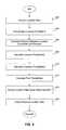
- FIG. 4is a flowchart of a method 400 .
- Method 400is used, for example, to adjust location data so that it corresponds to polyline features of a map.
- Method 400begins at step 402 .
- step 404for each location in the sequence of location data, polyline features within a radius R are found.
- polyline featuresmay be organized into bins, and finding polyline features may include using a map spatial index to get a list of all polyline features.
- the polyline featuresmay include information such as geometry information, street name information, address information, turn restriction information, intersection information, connectivity information, etc.
- the radius Ris selected and/or adjusted based on the accuracy/error associated with the location data and/or satellite-based positioning system device used to obtain the location data (e.g., the radius R used if the locations are known to be within 100 feet of the coordinates that are obtained should be larger than the radius R used if locations are known to be within 10 feet of the coordinates that are obtained).
- step 406for each location in the sequence of location data, distances between the locations and features found in step 404 are calculated.
- emission probabilitiesare calculated.
- An emission probabilityis calculated for each polyline feature within radius R of a location.
- the emission probabilityis a function of a feature and a location.
- the emission probabilityis a probability of obtaining the location, for example, from a GPS receiver given that the GPS receiver is actually at a location associated with a particular polyline feature.
- emission probability calculator 322calculates an emission probability for each polyline feature within radius R of the location data.
- prior probabilitiesare calculated.
- a prior probabilityis a probability that the start of the sequence of location data was measured at a particular polyline feature.
- prior probabilitiesare calculated for each feature within the radius R of an initial location to be equally likely. However, in the presence of other inputs, the prior probabilities may be skewed to favor a certain feature (or features).
- a sequence of adjusted/snapped location datais decoded.
- the sequence of adjusted location dataare modeled as hidden states in a hidden Markov model.
- the sequence of location dataare observable emissions from the hidden states that are given off with the calculated emission probability calculated in step 408 .
- the probability of transitioning to a first hidden statee.g., a first polyline feature
- a second hidden statee.g., a second polyline feature
- Step 414uses the Viterbi algorithm to decode the most likely sequence of hidden states (e.g., the sequence of adjusted location data).
- the Viterbi algorithmis fast and efficient. By using the Viterbi algorithm, method 400 saves resources, such as space and computational time.
- step 416the sequence of adjusted/snapped location data is outputted.
- the adjusted/snapped location datamay be written to a database.
- a servermay retrieve the adjusted/snapped location data from the database.
- the servermay format it for viewing by a user using a client. This example is illustrative and is not intended to limit the invention.
- method 400may include an additional step to use Kalman or particle filtering in conjunction with a hidden Markov model.
- Kalman or particle filteringmay be used to refine/adjust the accuracy of the hidden Markov model.
- the Kalman or particle filteringare applied after the snapped location data are determined using the hidden Markov model.
- method 400may use a probabilistic context-free grammar to model the sequence of polyline features.
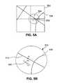
- FIGS. 5A and 5Bare diagrams that illustrate examples of how features within a radius R are recalled for a particular location. The examples show how to recall features for a particular location data. In practice, features are recalled for each location in a sequence of location data.
- FIG. 5Ashows four bins.
- One such binis bin 502 .
- Each binrepresents an area on a map. In an embodiment, each bin represents an area 50 meters by 50 meters square.
- each bincontains polyline features.
- a polyline featuremay be, for example, a portion of a street or an intersection.
- Polyline feature 508is an example polyline feature.
- Polyline feature 508may be associated with data such as, for example, a road name, road geometry, whether the roads is one-way or two-way, etc.
- a location 506(Y 1 ) can be represented by a set of coordinates and a heading. Each coordinate may include a latitude value and a longitude value. As an example, location data 506 may be obtained using a GPS receiver or other sensors, such as wheel encoders.
- step 404polyline features within a radius R are found.
- the bins containing the polyline featuresmust first be identified.
- the area within radius Ris shown as circle 504 . Portions of all four bins lie within circle 504 . Accordingly, all four bins are recalled so that the subset of the features within circle 504 can be determined.
- FIG. 5Bis a diagram that illustrates polyline features within circle 504 .
- two polyline featuresare shown within circle 504 .
- the polyline featuresare labeled 508 and 510 .
- the distances between GPS coordinates and polyline featuresare calculated in step 406 .
- FIG. 5Bshows an example distance d 11 between location Y 1 and the nearest point Z 1 on polyline feature 510 . Although only one distance is shown in the example, the distance between each of the polyline features 508 , 510 and the location Y 1 are calculated in practice.
- a heading differentialmay also be calculated.
- each of polyline features 508 , 510has a geometry that includes a heading. Heading differences may be calculated by taking the difference between the heading of the polyline features at the adjusted location (e.g., location Z 1 on feature 510 ) and the heading of location 506 (Y 1 ). In the example shown, the difference between the heading of location 506 and the heading of polyline feature 510 is shown by h 11 . Although only one heading difference is shown in the example, heading differential between each of the polyline features 508 , 510 and the location Y 1 are calculated in practice.
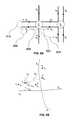
- FIG. 6Ais a diagram that illustrates an example of how transition probabilities are calculated according to an embodiment of the present invention.
- streetsare represented in embodiments by various polyline features (e.g., polyline features X 0 to X 9 ). Note that each side of the street is independently represented.
- “Connected”means that feature X 0 terminates at intersection I 1 and feature X 2 starts at intersection I 1 .
- there is a lower probability of transition between X 0 and X 6because those features are not directly connected.
- a vehicle carrying a GPS receivercould drive directly from X 0 to X 2 , so there is a high transition probability. But, a vehicle carrying a GPS receiver could not jump directly from X 0 to X 6 , so there is a lower transition probability (represented by line 604 ). Note that there is also a transition probability for transitioning from X 0 onto itself (represented by line 608 ).
- transition probabilitiescan vary based on feature information. For example, if a U-turn is allowed from X 0 to X 1 , the transition probability (represented by line 610 ) would be high, but if the U-turn is forbidden (i.e., it is a turn restriction), the transition probability would be low. Similarly, if the street is a one-way street, there may be a low probability of transitioning in a particular direction. For example, the transition probability for a transition from X 0 to X 4 (represented by line 606 ) is low since the vehicle cannot turn right from X 0 to X 4 since the latter is a one-way street and one cannot travel on it in the wrong direction.
- the function to adapt transition probabilitiescontains parameters.
- the parametersare selected using adaptive optimization.
- adaptive optimization algorithmsinclude, but are not limited to, a hill-climbing algorithm, a stochastic hill-climbing algorithm, an A-star algorithm, and a genetic algorithm.
- FIG. 6Bis a diagram that illustrates an example of how emission probabilities can be calculated according to an embodiment of the present invention.
- An emission probabilityis a function of a feature and a location.
- the emission probabilityis a probability of obtaining the location, for example, from a GPS receiver given that the GPS receiver is actually at a location associated with a feature.
- FIG. 6Bshows polyline features X 1 , X 2 , X 3 , and X 4 and a sequence of location data Y 1 , Y 2 , Y 3 , Y 4 and Y 5 .
- an emission probabilityis calculated for each polyline feature X 1 , X 2 , X 3 , and X 4 .
- an emission probabilitymay be a function of the distance between the polyline feature and the location and the heading differential between the polyline feature and the location.
- the emission probabilityis calculated using a Gaussian function.
- An example Gaussian functionis:
- an emission probabilitycontains parameters.
- the parametersmay be selected using adaptive optimization. Examples of an adaptive optimization algorithms are noted above.
- the emission probability of receiving location Y 2 while the receiver is at X 1is:
- the emission probability of receiving location Y 2 while the receiver is at X 3is:
- Distance d 32is larger than distance d 12
- heading differential h 32is larger than heading differential h 12 . Because d 32 is larger than d 12 and h 32 is higher than h 12 , the resulting probability P(Y 2
- FIG. 6Cis a diagram that illustrates an example of how location data may be snapped to points on a street.
- the adjusted locationsare determined using the Viterbi algorithm to decode the most likely sequence of hidden states (e.g., the sequence of adjusted location data).
- the sequence of location data Y 1 , Y 2 , Y 3 , Y 4 , and Y 5is adjusted to locations Z 1 , Z 2 , Z 3 , Z 4 , and Z 5 respectively, each of which lies on a polyline feature.
- two locations Y 1 and Y 2are adjusted to positions Z 1 and Z 2 respectively, both of which lie on the same polyline feature, X 1 .
- Y 3is snapped to point Z 3 which lies at the intersection.
- the polyline features X 1 , X 2 , X 3 , and X 4may be modeled as hidden states in a hidden Markov model.
- the entire sequence of locations Y 0 , Y 1 , Y 2 , Y 3 , and Y 4is optimally snapped to the sequence of locations Z 1 , Z 2 , Z 3 , Z 4 , and Z 5 respectively, which lie on the polyline features in the map. This is based on information about the geometry and connectivity of the street network. This additional constraint results in more accurate adjustment/snapping of location data.
- Z 1 , Z 2 , Z 3 , Z 4 , and Z 5may be the closest points to the locations Y 0 , Y 1 , Y 2 , Y 3 , and Y 4 on the corresponding polyline features X 1 , X 2 , X 3 , and X 4 .
Landscapes
- Engineering & Computer Science (AREA)
- Radar, Positioning & Navigation (AREA)
- Remote Sensing (AREA)
- Automation & Control Theory (AREA)
- Physics & Mathematics (AREA)
- General Physics & Mathematics (AREA)
- Position Fixing By Use Of Radio Waves (AREA)
- Navigation (AREA)
Abstract
Description
The present invention relates to satellite-based positioning systems. More particularly, it relates to registration of location data to street maps.
Global Positioning System (GPS) devices generate location data. The generated location data (e.g., latitude and longitude values), however, are not completely accurate. Particle filtering and Kalman filtering have both been used in an attempt to improve the accuracy of GPS location data. While these filtering techniques can be advantageous, both techniques have limitations. For example, both particle filtering and Kalman filtering do not give globally optimal solutions. Furthermore, both particle filtering and Kalman filtering typically require significant computing resources such as memory and processing time. Accordingly, there is a current need for new devices and techniques that overcome these and other deficiencies.
The present invention provides systems and methods for improving the accuracy of location data generated, for example, using a satellite-based positioning device, and applications thereof. In an embodiment, a system according to the present invention includes a spatial indexer, an emission probability calculator, a transition probability calculator, and a pose optimizer. The spatial indexer receives a sequence of location data corresponding to a plurality of locations. For each location, the spatial indexer identifies in a map database polyline features within a distance D from the location. The emission probability calculator calculates emission probabilities for the polyline features identified by the spatial indexer. Each emission probability Eijrepresents the probability that a street on the map represented by a polyline feature Pjemitted the observed location Ci. The transition probability calculator calculates transition probabilities for the polyline features identified by the spatial indexer. Each transition probability Txyrepresents the probability of a transition from a polyline feature Pxto a polyline feature Py. The pose optimizer adjusts the location data for the plurality of locations so that the adjusted location data correspond to polyline features belonging to a sequence of polyline features selected based on the emission probabilities calculated by the emission probability calculator and the transition probabilities calculated by the transition probability calculator.
In an embodiment, the present invention adjusts coordinates obtained using a satellite-based positioning device by (1) receiving a sequence of coordinates corresponding to a plurality of locations; (2) identifying in a map database, for each location, polyline features within a certain distance from the coordinates for the location; (3) calculating emission probabilities for the polyline features; (4) calculating transition probabilities for the polyline features; and (5) adjusting the coordinates for the plurality of locations so that the adjusted coordinates correspond to polyline features belonging to a sequence of polyline features selected based on the emission probabilities and the transition probabilities.
Besides improving accuracy, snapping GPS locations to street locations on a map enables novel geospatial applications and user interfaces by adding a large amount of meta-information to a location, such as the street address, navigation information (connected streets and intersections), nearby business information, etc.
Further embodiments, features, and advantages of the invention, as well as the structure and operation of the various embodiments of the invention are described in detail below with reference to accompanying drawings.
Embodiments of the invention are described with reference to the accompanying drawings. In the drawings, like reference numbers may indicate identical or functionally similar elements.
The present invention provides systems and methods for improving the accuracy of location data generated, for example, using a satellite-based positioning device, and applications thereof. While the present invention is described herein with reference to illustrative embodiments for particular applications, it should be understood that the invention is not limited thereto. Those skilled in the art with access to the teachings provided herein will recognize additional modifications, applications, and embodiments within the scope thereof and additional fields in which the invention would be of significant utility.
In an embodiment, eachlocation 110A-110N includes both coordinate and heading information. The coordinate information can be, for example, latitude and longitude information. As noted herein, the location data can be generated using a satellite-based positioning system device, such as a GPS receiver, carried in a vehicle. The invention is not limited, however, to using just a GPS receiver. For example, the location data can be generated using other devices and/or sensors such as a vehicle wheel encoder. A vehicle wheel encoder estimates where a vehicle is located based on wheel movements. Using the present invention, it is possible to improve the accuracy of noisy measurements obtained using such devices and/or sensors and to correctly snap location data obtained using these devices and/or sensors to a street.
As illustrated inFIG. 1 , the sequence of location data106 (e.g.,locations 110A-110N) is adjusted to form the sequence of adjusted location data108 (e.g., adjustedlocations 112A-112N). The sequence of adjustedlocation data 108 corresponds to the set of polyline features that representstreet 104 inmap 100. Thus, each adjustedlocation 112A-112N corresponds to a coordinate that lies alongstreet 104 and has a heading corresponding to that associated withstreet 104.
As discussed earlier, conventional methods of snapping location data to a street include Kalman and particle filtering. Kalman and particle filtering snap location data on a point-by-point basis. For example, Kalman and particle filtering would snap a point (e.g.,location 110A) to a new point (e.g.,location 112A) without necessarily using information from all the other points (e.g., locations110B-N) optimally. Embodiments of the present invention, however, optimally snap entire sequences of locations to sequences of polyline features that represent a street. These embodiments take advantage, for example, of the connectivity and heading information about the street. In other words, these embodiments take into consideration that a GPS receiver carried in a vehicle can not easily move from one street to another, unless the streets are connected. Taking into consideration this additional information enables embodiments of the present invention to adjust/snap correctly sequences of location data.
In an embodiment,system 200 includes aGPS track database 202, amap database 204, aprocessing pipeline server 210, and astreet track database 220. Data stored instreet track database 220 is viewed, for example, using astreet track server 230 and astreet track client 250 that communicates withstreet track server 230 over anetwork 240 or using aviewer 260 coupled tostreet track database 220. Each of the elements shown inFIG. 2 can be any type of computing device. Example computing devices include, but are not limited to, a computer, a workstation, a distributed computing system, an embedded system, a stand-alone electronic device, a networked device, a mobile device, a rack server, a portable GPS device, a television, etc.
In an embodiment,map database 204 includes a feature index. The feature index maps the feature ID of a polyline feature to feature data. In the example of a road, feature data can include a road name, road geometry, road connectivity, whether the road is one-way or two-way, turn restrictions (e.g., no U-turns allowed), etc. Intersection features can contain feature IDs of roads terminating at the intersection. In this way, the feature index maintains, for example, information on the connectivity of the features.
In an embodiment, each polyline feature is accessible using a spatial index. A spatial index organizes polyline features into geographic areas called bins. In an embodiment, bins have a standard size (e.g., 50 meters by 50 meters), and each bin has a unique geographic ID (e.g., an s2cellID). Bins contain a list of feature IDs that lie within their associated geographical areas.
In an embodiment, data stored instreet track database 220 is viewed usingstreet track server 230 and astreet track client 250 that communicates withstreet track server 230 over anetwork 240. In an embodiment,street track client 250 includes a web browser that is used to view the data. The web browser can display, for example, an adjusted location data sequence as a line overlaying a map. When a user selects a point on a line, a photographic image taken from that location can be displayed. This example is merely illustrative and is not meant to limit the present invention.
In an embodiment,street track client 250 communicates withstreet track server 230 over anetwork 240 or a group of networks that together comprise thenetwork 240 illustrated inFIG. 2 .Network 240 can be any network or combination of networks that facilitate data communication. In embodiments,network 240 can include, but is not limited to, a local area network, a medium area network, and/or a wide area network such as the Internet.Network 240 can support protocols and technology including, but not limited to, World Wide Web protocols and/or services. Intermediate web servers, gateways, or other servers may be provided betweenstreet track server 230 andstreet track client 250.
As illustrated inFIG. 3 ,spatial indexer 212 receives a sequence oflocation data 302 from GPSstreet track database 202. Sequence oflocation data 302 may be collected, for example, by one or more vehicles with GPS receivers and/or other sensors (e.g., wheel encoders). Each location in the sequence of location data can include coordinate and/or heading values. In an embodiment, each location in sequence oflocation data 302 may be collected at regular time and/or distance intervals. In an embodiment, the sequence oflocation data 302 may be received in real-time or near real-time. This means that the most recently collected location data in the sequence of location data was received byspatial indexer 212 soon after it was collected.
For each location in sequence oflocation data 302,feature finder 312 ofspatial indexer 212 identifies polyline features within a radius R stored inmap database 204. The radius R should be large enough to cover all possible polyline features to which the location could map. Therefore, the radius R should be larger, for example, than the error range, at a particular confidence interval, of the GPS receiver used to determine the location.
In an embodiment,feature finder 312 identifies features by recalling the s2cellID for each bin within radiusR. Feature finder 312 uses the spatial index to get a list of all polyline features and corresponding feature information associated with bins within radius R. As shown inFIG. 3 , the retrieved polyline features are identified as map features308. Map features308 include, for example, information such as geometry information, street name information, address information, turn restriction information, connectivity information, etc.
In certain situations, the bins may cover more area than the circle of radius R. As a result, polyline features may be recalled from map adatabase 204 that are outside the area of interest (e.g., the circle of radius R). Thus, in an embodiment,feature finder 312 includes logic that selects only features that lie within the area of interest. An example of this is described below.
Afterfeature finder 312 recalls map features308 for each location in the sequence oflocation data 302,distance calculator 314 calculates a distance between each location and each feature within radius R of that location. Optionally,spatial indexer 212 may also calculate a heading differential. Each of the polyline features has an associated geometry. A heading can be determined from the geometry. As an example, if the polyline feature is a portion of a curved road, a heading can be determined by taking the derivative of the curve. A heading difference may be calculated by taking the difference between the heading associated with the polyline feature and the heading associated with the location.
In an embodiment,emission probability calculator 322 ofpose optimizer 214 calculates an emission probability. The emission probability is a function of a feature and a location. The emission probability is a probability of obtaining the location, for example, from the GPS receiver given that the GPS receiver is actually at a location associated with a particular map feature. For each location,emission probability calculator 322 calculates an emission probability for each feature within radius R of the location. How to calculate emission probabilities is described in more detail below.
The Viterbi algorithm is fast and memory efficient. By using the Viterbi algorithm,Viterbi decoder 326 saves computing resources, such as memory and processor time. In embodiments, pose optimizer214 may also use Kalman or particle filtering in conjunction with hidden Markov models. This approach is discussed in more detail below. In an embodiment, pose optimizer214 may model a sequence of polyline features as a probabilistic context-free grammar.
Once theViterbi decoder 326 determines the sequence of adjusted location data,processing pipeline server 210 writes the sequence of adjusted location data tostreet track database 220. InFIG. 3 , the adjusted location data is represented by snappedlocation data 304.Snapped location data 304 is the sequence of location data that has been adjusted to correspond to features stored inmap database 204.
Each offeature finder 312,distance calculator 314,emission probability calculator 322,transition probability calculator 324,prior probability calculator 328, andViterbi decoder 326 may be implemented in hardware, software, firmware, or any combination thereof.
Instep 402, a sequence of location data is received, for example using a satellite-based positioning system device (e.g. a GPS receiver). Each location can include coordinate and heading values. The coordinate values can be latitude and longitude values. In an embodiment, the location data is generated/received, for example, by one or more GPS receivers in a vehicle and/or other sensors such as wheel encoders. In embodiments, the location data may be received in real-time or near real-time.
Instep 404, for each location in the sequence of location data, polyline features within a radius R are found. In an embodiment, polyline features may be organized into bins, and finding polyline features may include using a map spatial index to get a list of all polyline features. The polyline features may include information such as geometry information, street name information, address information, turn restriction information, intersection information, connectivity information, etc. In an embodiment, the radius R is selected and/or adjusted based on the accuracy/error associated with the location data and/or satellite-based positioning system device used to obtain the location data (e.g., the radius R used if the locations are known to be within 100 feet of the coordinates that are obtained should be larger than the radius R used if locations are known to be within 10 feet of the coordinates that are obtained).
Instep 406, for each location in the sequence of location data, distances between the locations and features found instep 404 are calculated.
Instep 408, for each location in the sequence of location data, emission probabilities are calculated. An emission probability is calculated for each polyline feature within radius R of a location. The emission probability is a function of a feature and a location. The emission probability is a probability of obtaining the location, for example, from a GPS receiver given that the GPS receiver is actually at a location associated with a particular polyline feature. For each location,emission probability calculator 322 calculates an emission probability for each polyline feature within radius R of the location data.
Instep 410, transition probabilities are calculated. A transition probability is a probability of transitioning to a location of a feature given that the GPS receiver is at another feature. In an example, if a transition is allowed from one road to another (e.g., the roads meet at an intersection, and there are no turn restrictions), the transition is associated with a high probability. A disallowed transition (e.g., a transition between two roads that are not connected), is associated with low probability. How transition probabilities are calculated is described in more detail below.
Instep 412, prior probabilities are calculated. A prior probability is a probability that the start of the sequence of location data was measured at a particular polyline feature. In an embodiment, prior probabilities are calculated for each feature within the radius R of an initial location to be equally likely. However, in the presence of other inputs, the prior probabilities may be skewed to favor a certain feature (or features).
Instep 414, a sequence of adjusted/snapped location data is decoded. In embodiments of this invention, the sequence of adjusted location data are modeled as hidden states in a hidden Markov model. In the hidden Markov model, the sequence of location data are observable emissions from the hidden states that are given off with the calculated emission probability calculated instep 408. The probability of transitioning to a first hidden state (e.g., a first polyline feature) given, for example, that a GPS receiver is at a second hidden state (e.g., a second polyline feature) is defined by the transition probabilities calculated instep 410. The probability of the sequence of adjusted location data starting at a particular polyline feature is determined instep 412. Step414 uses the Viterbi algorithm to decode the most likely sequence of hidden states (e.g., the sequence of adjusted location data). The Viterbi algorithm is fast and efficient. By using the Viterbi algorithm,method 400 saves resources, such as space and computational time.
Instep 416, the sequence of adjusted/snapped location data is outputted. In an example embodiment, the adjusted/snapped location data may be written to a database. A server may retrieve the adjusted/snapped location data from the database. The server may format it for viewing by a user using a client. This example is illustrative and is not intended to limit the invention.
As show in the above embodiment, an entire sequence of location data is adjusted/snapped to the location of a sequences of polyline features. By snapping an entire sequence, as opposed to just individual locations, this embodiment takes into account, for example, the continuity of streets. This constraint enables embodiments of the present invention to correctly adjust/snap location data.
In embodiments,method 400 may include an additional step to use Kalman or particle filtering in conjunction with a hidden Markov model. As an example, Kalman or particle filtering may be used to refine/adjust the accuracy of the hidden Markov model. In that example, the Kalman or particle filtering are applied after the snapped location data are determined using the hidden Markov model.
In an embodiment,method 400 may use a probabilistic context-free grammar to model the sequence of polyline features.
In embodiments, each bin contains polyline features. A polyline feature may be, for example, a portion of a street or an intersection.Polyline feature 508 is an example polyline feature.Polyline feature 508 may be associated with data such as, for example, a road name, road geometry, whether the roads is one-way or two-way, etc.
As shown inFIG. 5A , a location506 (Y1) can be represented by a set of coordinates and a heading. Each coordinate may include a latitude value and a longitude value. As an example,location data 506 may be obtained using a GPS receiver or other sensors, such as wheel encoders.
Referring toFIG. 4 again, recall that instep 404, polyline features within a radius R are found. To recall features within radius R, the bins containing the polyline features must first be identified. In the example inFIG. 5A , the area within radius R is shown ascircle 504. Portions of all four bins lie withincircle 504. Accordingly, all four bins are recalled so that the subset of the features withincircle 504 can be determined.
As described herein, a heading differential may also be calculated. In an embodiment, each of polyline features508,510 has a geometry that includes a heading. Heading differences may be calculated by taking the difference between the heading of the polyline features at the adjusted location (e.g., location Z1on feature510) and the heading of location506 (Y1). In the example shown, the difference between the heading oflocation 506 and the heading ofpolyline feature 510 is shown by h11. Although only one heading difference is shown in the example, heading differential between each of the polyline features508,510 and the location Y1are calculated in practice.
The distances and headings described above are determined for use in calculating emission probabilities. Calculating emission probability is discussed in more detail below with reference toFIG. 6B .
In embodiments, transition probabilities can vary based on feature information. For example, if a U-turn is allowed from X0to X1, the transition probability (represented by line610) would be high, but if the U-turn is forbidden (i.e., it is a turn restriction), the transition probability would be low. Similarly, if the street is a one-way street, there may be a low probability of transitioning in a particular direction. For example, the transition probability for a transition from X0to X4(represented by line606) is low since the vehicle cannot turn right from X0to X4since the latter is a one-way street and one cannot travel on it in the wrong direction.
In an embodiment, the function to adapt transition probabilities contains parameters. The parameters are selected using adaptive optimization. Examples of adaptive optimization algorithms include, but are not limited to, a hill-climbing algorithm, a stochastic hill-climbing algorithm, an A-star algorithm, and a genetic algorithm.
where Ymis a location; Xnis a polyline feature; dmnis the distance between location Ymand polyline feature Xn; hmnis the heading differential between location Ymand polyline feature Xn; and A, B, σD, and σHare parameters. Parameters A and B control the relative weight of distance and heading respectively. Parameter σDcontrols how quickly the emission probability decreases as the distance increases. Parameter σHcontrols how quickly the emission probability decreases as the heading differential increases.
In an embodiment, an emission probability contains parameters. The parameters may be selected using adaptive optimization. Examples of an adaptive optimization algorithms are noted above. In the example shown inFIG. 6B , the emission probability of receiving location Y2while the receiver is at X1is:
In the example shown inFIG. 6B , the emission probability of receiving location Y2while the receiver is at X3is:
Distance d32is larger than distance d12, and heading differential h32is larger than heading differential h12. Because d32is larger than d12and h32is higher than h12, the resulting probability P(Y2|X1) is going to be larger than the probability P(Y2|X1). As a result, the location Y2is more likely to be adjusted/snapped to a location on X1than to a location on X3.
In the example shown inFIG. 6C , the sequence of location data Y1, Y2, Y3, Y4, and Y5is adjusted to locations Z1, Z2, Z3, Z4, and Z5respectively, each of which lies on a polyline feature. Note that in this example, two locations Y1and Y2are adjusted to positions Z1and Z2respectively, both of which lie on the same polyline feature, X1. This is possible because self-transitions between polyline features are allowed. Y3is snapped to point Z3which lies at the intersection. As discussed earlier, the polyline features X1, X2, X3, and X4may be modeled as hidden states in a hidden Markov model. As described herein, the entire sequence of locations Y0, Y1, Y2, Y3, and Y4is optimally snapped to the sequence of locations Z1, Z2, Z3, Z4, and Z5respectively, which lie on the polyline features in the map. This is based on information about the geometry and connectivity of the street network. This additional constraint results in more accurate adjustment/snapping of location data.
In an example, not intended to limit the present invention, Z1, Z2, Z3, Z4, and Z5may be the closest points to the locations Y0, Y1, Y2, Y3, and Y4on the corresponding polyline features X1, X2, X3, and X4.
It is to be appreciated that the detailed description section, and not the summary and abstract sections, is intended to be used to interpret the claims. The summary and abstract sections may set forth one or more but not all exemplary embodiments of the present invention as contemplated by the inventor(s), and thus, are not intended to limit the present invention and the appended claims in any way.
The present invention has been described above with the aid of functional building blocks illustrating the implementation of specified functions and relationships thereof. The boundaries of these functional building blocks have been arbitrarily defined herein for the convenience of the description. Alternate boundaries can be defined so long as the specified functions and relationships thereof are appropriately performed.
The foregoing description of the specific embodiments will so fully reveal the general nature of the invention that others can, by applying knowledge within the skill of the art, readily modify and/or adapt for various applications such specific embodiments, without undue experimentation, without departing from the general concept of the present invention. Therefore, such adaptations and modifications are intended to be within the meaning and range of equivalents of the disclosed embodiments, based on the teaching and guidance presented herein. It is to be understood that the phraseology or terminology herein is for the purpose of description and not of limitation, such that the terminology or phraseology of the present specification is to be interpreted by the skilled artisan in light of the teachings and guidance.
The breadth and scope of the present invention should not be limited by any of the above-described exemplary embodiments, but should be defined only in accordance with the following claims and their equivalents.
Claims (20)
1. A method for adjusting coordinates obtained using a satellite-based positioning system device, comprising:
(1) receiving a sequence of coordinates corresponding to a plurality of locations;
(2) identifying in a map database, for each location, polyline features within a first distance from the coordinates for the location;
(3) calculating emission probabilities for the polyline features identified in (2), wherein each emission probability Eijrepresents the probability of obtaining coordinates Cifor a location represented by a polyline feature Pj;
(4) calculating transition probabilities for the polyline feature identified in (2), wherein each transition probability Txyrepresents the probability of a transition from a polyline feature Pxto a polyline feature Py; and
(5) adjusting the sequence of coordinates corresponding to the plurality of locations so that the adjusted coordinates correspond to polyline features belonging to a sequence of polyline features selected based on the emission probabilities calculated in (3) and the transition probabilities calculated in (4),
wherein steps (1)-(5) are performed by at least one computing device.
2. The method ofclaim 1 , farther comprising:
(6) adjusting the sequence of coordinates corresponding to the plurality of locations using information from sensors other than the satellite-based positioning system device.
3. The method ofclaim 1 , wherein (2) comprises selecting the first distance based on an accuracy associated with the sequence of coordinates corresponding to the plurality of locations.
4. The method ofclaim 1 , wherein (3) comprises calculating emission probabilities for the polyline features identified in (2) based on an error associated with the satellite-based positioning system device.
5. The method ofclaim 1 , wherein (5) further comprises:
(a) modeling the sequence of polyline features as a Hidden Markov Model; and
(b) decoding the adjusted coordinates using Viterbi decoding.
6. The method ofclaim 1 , wherein (1) through (5) are performed by the satellite-based positioning system device while the device is carried in a vehicle.
7. A method for adjusting location data, comprising:
(1) identifying in a map database, for a plurality of locations, polyline features within a first distance from each location;
(2) calculating emission probabilities for the polyline features identified in (1), wherein each emission probability Eijrepresents the probability of obtaining location Cifor a location on the map represented by a polyline feature Pj;
(3) calculating transition probabilities for the polyline feature identified in (1), wherein each transition probability Txyrepresents the probability of a transition from a polyline feature Pxto a polyline feature Py; and
(4) adjusting the plurality of locations so that the adjusted locations correspond to polyline features belonging to a sequence of polyline features selected based on the emission probabilities calculated in (2) and the transition probabilities calculated in (3),
wherein steps (1)-(4) are performed by at least one computing device.
8. The method ofclaim 7 , wherein the plurality of locations have associated heading values, and (4) comprises adjusting the associated heading values.
9. The method ofclaim 7 , wherein (2) comprises calculating emission probabilities based on a Gaussian probability function.
10. The method ofclaim 9 , wherein (2) comprises using adaptive optimization to select parameters for the Gaussian probability function.
11. The method ofclaim 7 , wherein (3) comprises calculating transition probabilities using at least one of turn restriction information, intersection information, and one-way street information stored in the map database.
12. The method ofclaim 7 , wherein (5) comprises modeling the sequence of polyline features as a Hidden Markov Model.
13. The method ofclaim 7 , further comprising:
(5) adjusting the plurality of locations with particle filtering.
14. The method ofclaim 7 , further comprising:
(5) adjusting the plurality of locations with Kalman filtering.
15. The method ofclaim 7 , wherein (5) comprises modeling the sequence of polyline features as a probabilistic context free grammar.
16. A system for adjusting location data, comprising:
a spatial indexer that receives a sequence of location data corresponding to a plurality of locations and identifies in a map database, for each location, polyline features within a first distance from the coordinates for the location;
an emission probability calculator that calculates emission probabilities for the polyline features identified by the spatial indexer, wherein each emission probability Eijrepresents the probability of obtaining location Cifor a location on the map represented by a polyline feature Pj;
a transition probability calculator that calculates transition probabilities for the polyline feature identified by the spatial indexer, wherein each transition probability Txyrepresents the probability of a transition from a polyline feature Pxto a polyline feature Py; and
a pose optimizer that adjusts the location data for the plurality of locations so that the adjusted location data correspond to polyline features belonging to a sequence polyline features selected based on the calculate emission probabilities and the calculated transition probabilities.
17. The system ofclaim 16 , wherein the location data includes heading values.
18. The system ofclaim 16 , wherein the emission probability calculator calculates the emission probabilities using a Gaussian probability function.
19. The system ofclaim 16 , wherein the transition probability calculator calculates transition probabilities using at least one of turn restriction information, intersection information, and one-way street information stored in the map database.
20. The system of claim wherein the pose optimizer includes a Viterbi decoder.
Priority Applications (1)
| Application Number | Priority Date | Filing Date | Title |
|---|---|---|---|
| US11/870,265US8209121B1 (en) | 2007-10-10 | 2007-10-10 | Registration of location data to street maps using hidden markov models, and application thereof |
Applications Claiming Priority (1)
| Application Number | Priority Date | Filing Date | Title |
|---|---|---|---|
| US11/870,265US8209121B1 (en) | 2007-10-10 | 2007-10-10 | Registration of location data to street maps using hidden markov models, and application thereof |
Publications (1)
| Publication Number | Publication Date |
|---|---|
| US8209121B1true US8209121B1 (en) | 2012-06-26 |
Family
ID=46272952
Family Applications (1)
| Application Number | Title | Priority Date | Filing Date |
|---|---|---|---|
| US11/870,265Active2031-02-02US8209121B1 (en) | 2007-10-10 | 2007-10-10 | Registration of location data to street maps using hidden markov models, and application thereof |
Country Status (1)
| Country | Link |
|---|---|
| US (1) | US8209121B1 (en) |
Cited By (11)
| Publication number | Priority date | Publication date | Assignee | Title |
|---|---|---|---|---|
| US8718932B1 (en) | 2011-06-01 | 2014-05-06 | Google Inc. | Snapping GPS tracks to road segments |
| US8977074B1 (en)* | 2010-09-29 | 2015-03-10 | Google Inc. | Urban geometry estimation from laser measurements |
| CN104850604A (en)* | 2015-05-04 | 2015-08-19 | 华中科技大学 | Tensor-based user track mining method |
| US9568323B2 (en)* | 2011-10-17 | 2017-02-14 | Microsoft Technology Licensing, Llc | Location determination |
| US9625262B2 (en) | 2012-10-25 | 2017-04-18 | Honeywell International Inc. | Smoothed navigation solution using filtered resets |
| US20190154452A1 (en)* | 2016-04-01 | 2019-05-23 | Here Global B.V. | Road Geometry Matching with Componentized Junction Models |
| JP2019519041A (en)* | 2016-06-07 | 2019-07-04 | ロベルト・ボッシュ・ゲゼルシャフト・ミト・ベシュレンクテル・ハフツングRobert Bosch Gmbh | Method, apparatus and system for detecting reverse running driver |
| US20200049512A1 (en)* | 2018-08-09 | 2020-02-13 | Here Global B.V. | Method and apparatus for map matching trace points to a digital map |
| CN111177285A (en)* | 2018-11-09 | 2020-05-19 | 厦门雅迅网络股份有限公司 | Electronic map accurate positioning method, terminal equipment and storage medium |
| EP3657841A4 (en)* | 2017-08-15 | 2020-05-27 | Huawei Technologies Co., Ltd. | Method and device for obtaining emission probability, transfer probability and sequence positioning |
| WO2023105445A1 (en) | 2021-12-08 | 2023-06-15 | Terrastar Ag | Method and system for detecting, processing, and displaying location data |
Citations (39)
| Publication number | Priority date | Publication date | Assignee | Title |
|---|---|---|---|---|
| US6038559A (en)* | 1998-03-16 | 2000-03-14 | Navigation Technologies Corporation | Segment aggregation in a geographic database and methods for use thereof in a navigation application |
| US6092076A (en)* | 1998-03-24 | 2000-07-18 | Navigation Technologies Corporation | Method and system for map display in a navigation application |
| US6118404A (en)* | 1998-01-21 | 2000-09-12 | Navigation Technologies Corporation | Method and system for representation of overlapping features in geographic databases |
| US6202023B1 (en)* | 1996-08-22 | 2001-03-13 | Go2 Systems, Inc. | Internet based geographic location referencing system and method |
| US20030006973A1 (en)* | 1998-05-11 | 2003-01-09 | Katsuyuki Omura | Coordinate position inputting/detecting device, a method for inputting/detecting the coordinate position, and a display board system |
| US6631323B2 (en)* | 2000-05-30 | 2003-10-07 | Northrop Grumman Corporation | Method and apparatus for improving performance of an inertial navigation system having global positioning system corrections |
| US20040049337A1 (en)* | 1997-08-19 | 2004-03-11 | Siemens Automotive Corporation, A Dalaware Corporation | Vehicle information system |
| US6708109B1 (en)* | 2002-07-18 | 2004-03-16 | Hewlett-Packard Development Company, L.P. | Accurate targeting from imprecise locations |
| US6782319B1 (en)* | 2002-11-26 | 2004-08-24 | Navteq North America, Llc | Method for organizing map data |
| US20040181335A1 (en)* | 2003-03-14 | 2004-09-16 | Samsung Electronics Co., Ltd. | Apparatus for detecting location of movable body in navigation system and method thereof |
| US6862526B2 (en)* | 2000-12-15 | 2005-03-01 | Trimble Navigation Limited | GPS correction methods, apparatus and signals |
| US20050131635A1 (en)* | 2002-05-31 | 2005-06-16 | Ekahau Oy | Error estimate concerning a target device's location operable to move in a wireless environment |
| US6950059B2 (en)* | 2002-09-23 | 2005-09-27 | Topcon Gps Llc | Position estimation using a network of a global-positioning receivers |
| US6965827B1 (en)* | 2000-10-30 | 2005-11-15 | Board Of Trustees Of The University Of Illinois | Method and system for tracking moving objects |
| US20050288911A1 (en)* | 2004-06-28 | 2005-12-29 | Porikli Fatih M | Hidden markov model based object tracking and similarity metrics |
| US6983202B2 (en)* | 2002-11-22 | 2006-01-03 | Electronic Data Systems Corporation | Implementing geo-fencing on mobile devices |
| US20060041375A1 (en)* | 2004-08-19 | 2006-02-23 | Geographic Data Technology, Inc. | Automated georeferencing of digitized map images |
| US20060088214A1 (en)* | 2004-10-22 | 2006-04-27 | Xerox Corporation | System and method for identifying and labeling fields of text associated with scanned business documents |
| US20060087507A1 (en)* | 2004-10-25 | 2006-04-27 | Sony Corporation | Information processing apparatus and method, program, and navigation apparatus |
| US20060125828A1 (en)* | 2002-02-11 | 2006-06-15 | Landnet Corporation | Land software tool |
| US7096117B1 (en)* | 2004-01-20 | 2006-08-22 | Navteq North America, Llc | Method and system of polyline generation for rendering a richly attributed representation of a geographic region |
| US20070061072A1 (en)* | 2005-09-12 | 2007-03-15 | Markus Wuersch | System and method for the selection of a unique geographic feature |
| US20070118279A1 (en)* | 2005-11-21 | 2007-05-24 | Denso Corporation | System and method for facility search |
| US20070142050A1 (en)* | 2005-12-19 | 2007-06-21 | Nortel Networks Limited | Method and system for handover in cellular wireless using route programming and training processes |
| US7299126B2 (en)* | 2003-11-03 | 2007-11-20 | International Business Machines Corporation | System and method for evaluating moving queries over moving objects |
| US20080010605A1 (en)* | 2006-06-12 | 2008-01-10 | Metacarta, Inc. | Systems and methods for generating and correcting location references extracted from text |
| US20080075357A1 (en)* | 2006-09-26 | 2008-03-27 | Samsung Electronics Co., Ltd. | Method and apparatus to determine robot location using omni-directional image |
| US20080094250A1 (en)* | 2006-10-19 | 2008-04-24 | David Myr | Multi-objective optimization for real time traffic light control and navigation systems for urban saturated networks |
| US20080240497A1 (en)* | 2007-03-27 | 2008-10-02 | Porikli Fatih M | Method for tracking objects in videos using forward and backward tracking |
| US20080248813A1 (en)* | 2007-04-06 | 2008-10-09 | Palm, Inc. | System and Methods for Obtaining Coarse Location for a Mobile Device |
| US20080270366A1 (en)* | 2005-06-28 | 2008-10-30 | Metacarta, Inc. | User interface for geographic search |
| US20080284643A1 (en)* | 2007-05-16 | 2008-11-20 | Scherzinger Bruno M | Post-mission high accuracy position and orientation system |
| US20090005972A1 (en)* | 2007-06-29 | 2009-01-01 | De Koning Wilhelmus G | Systems and Methods for Determining Location Using Cellular Transition Patterns |
| US20090040229A1 (en)* | 2007-08-06 | 2009-02-12 | Andrew Stitt | Generalization of Features in a Digital Map Using Round Number Coordinates |
| US20090093959A1 (en)* | 2007-10-04 | 2009-04-09 | Trimble Navigation Limited | Real-time high accuracy position and orientation system |
| US20090187388A1 (en)* | 2006-02-28 | 2009-07-23 | National Research Council Of Canada | Method and system for locating landmarks on 3d models |
| US7660667B2 (en)* | 2004-05-19 | 2010-02-09 | Honda Motor Co., Ltd. | System and method for off route processing |
| US20100049765A1 (en)* | 2005-02-02 | 2010-02-25 | Michael Asher | Geocoding Method Using Multidimensional Vector Spaces |
| US7921136B1 (en)* | 2004-03-11 | 2011-04-05 | Navteq North America, Llc | Method and system for using geographic data for developing scenes for entertainment features |
- 2007
- 2007-10-10USUS11/870,265patent/US8209121B1/enactiveActive
Patent Citations (46)
| Publication number | Priority date | Publication date | Assignee | Title |
|---|---|---|---|---|
| US6202023B1 (en)* | 1996-08-22 | 2001-03-13 | Go2 Systems, Inc. | Internet based geographic location referencing system and method |
| US20040049337A1 (en)* | 1997-08-19 | 2004-03-11 | Siemens Automotive Corporation, A Dalaware Corporation | Vehicle information system |
| US6118404A (en)* | 1998-01-21 | 2000-09-12 | Navigation Technologies Corporation | Method and system for representation of overlapping features in geographic databases |
| US6038559A (en)* | 1998-03-16 | 2000-03-14 | Navigation Technologies Corporation | Segment aggregation in a geographic database and methods for use thereof in a navigation application |
| US6092076A (en)* | 1998-03-24 | 2000-07-18 | Navigation Technologies Corporation | Method and system for map display in a navigation application |
| US20030006973A1 (en)* | 1998-05-11 | 2003-01-09 | Katsuyuki Omura | Coordinate position inputting/detecting device, a method for inputting/detecting the coordinate position, and a display board system |
| US6608619B2 (en)* | 1998-05-11 | 2003-08-19 | Ricoh Company, Ltd. | Coordinate position inputting/detecting device, a method for inputting/detecting the coordinate position, and a display board system |
| US6631323B2 (en)* | 2000-05-30 | 2003-10-07 | Northrop Grumman Corporation | Method and apparatus for improving performance of an inertial navigation system having global positioning system corrections |
| US6965827B1 (en)* | 2000-10-30 | 2005-11-15 | Board Of Trustees Of The University Of Illinois | Method and system for tracking moving objects |
| US6862526B2 (en)* | 2000-12-15 | 2005-03-01 | Trimble Navigation Limited | GPS correction methods, apparatus and signals |
| US20080130955A1 (en)* | 2002-02-11 | 2008-06-05 | Landnet Corporation | Land software tool |
| US20060125828A1 (en)* | 2002-02-11 | 2006-06-15 | Landnet Corporation | Land software tool |
| US20050131635A1 (en)* | 2002-05-31 | 2005-06-16 | Ekahau Oy | Error estimate concerning a target device's location operable to move in a wireless environment |
| US6708109B1 (en)* | 2002-07-18 | 2004-03-16 | Hewlett-Packard Development Company, L.P. | Accurate targeting from imprecise locations |
| US6950059B2 (en)* | 2002-09-23 | 2005-09-27 | Topcon Gps Llc | Position estimation using a network of a global-positioning receivers |
| US6983202B2 (en)* | 2002-11-22 | 2006-01-03 | Electronic Data Systems Corporation | Implementing geo-fencing on mobile devices |
| US6782319B1 (en)* | 2002-11-26 | 2004-08-24 | Navteq North America, Llc | Method for organizing map data |
| US20040181335A1 (en)* | 2003-03-14 | 2004-09-16 | Samsung Electronics Co., Ltd. | Apparatus for detecting location of movable body in navigation system and method thereof |
| US7299126B2 (en)* | 2003-11-03 | 2007-11-20 | International Business Machines Corporation | System and method for evaluating moving queries over moving objects |
| US7096117B1 (en)* | 2004-01-20 | 2006-08-22 | Navteq North America, Llc | Method and system of polyline generation for rendering a richly attributed representation of a geographic region |
| US7921136B1 (en)* | 2004-03-11 | 2011-04-05 | Navteq North America, Llc | Method and system for using geographic data for developing scenes for entertainment features |
| US7660667B2 (en)* | 2004-05-19 | 2010-02-09 | Honda Motor Co., Ltd. | System and method for off route processing |
| US20050288911A1 (en)* | 2004-06-28 | 2005-12-29 | Porikli Fatih M | Hidden markov model based object tracking and similarity metrics |
| US7263472B2 (en)* | 2004-06-28 | 2007-08-28 | Mitsubishi Electric Research Laboratories, Inc. | Hidden markov model based object tracking and similarity metrics |
| US20060041375A1 (en)* | 2004-08-19 | 2006-02-23 | Geographic Data Technology, Inc. | Automated georeferencing of digitized map images |
| US20060088214A1 (en)* | 2004-10-22 | 2006-04-27 | Xerox Corporation | System and method for identifying and labeling fields of text associated with scanned business documents |
| US20060087507A1 (en)* | 2004-10-25 | 2006-04-27 | Sony Corporation | Information processing apparatus and method, program, and navigation apparatus |
| US20100049765A1 (en)* | 2005-02-02 | 2010-02-25 | Michael Asher | Geocoding Method Using Multidimensional Vector Spaces |
| US20080270366A1 (en)* | 2005-06-28 | 2008-10-30 | Metacarta, Inc. | User interface for geographic search |
| US20070061072A1 (en)* | 2005-09-12 | 2007-03-15 | Markus Wuersch | System and method for the selection of a unique geographic feature |
| US20080262723A1 (en)* | 2005-09-12 | 2008-10-23 | Intelligent Spatial Technologies, Inc. | System and method for the selection of a unique geographic feature |
| US20070118279A1 (en)* | 2005-11-21 | 2007-05-24 | Denso Corporation | System and method for facility search |
| US20070142050A1 (en)* | 2005-12-19 | 2007-06-21 | Nortel Networks Limited | Method and system for handover in cellular wireless using route programming and training processes |
| US20090187388A1 (en)* | 2006-02-28 | 2009-07-23 | National Research Council Of Canada | Method and system for locating landmarks on 3d models |
| US20080010262A1 (en)* | 2006-06-12 | 2008-01-10 | Metacarta, Inc. | System and methods for providing statstically interesting geographical information based on queries to a geographic search engine |
| US20080010605A1 (en)* | 2006-06-12 | 2008-01-10 | Metacarta, Inc. | Systems and methods for generating and correcting location references extracted from text |
| US20080075357A1 (en)* | 2006-09-26 | 2008-03-27 | Samsung Electronics Co., Ltd. | Method and apparatus to determine robot location using omni-directional image |
| US20080094250A1 (en)* | 2006-10-19 | 2008-04-24 | David Myr | Multi-objective optimization for real time traffic light control and navigation systems for urban saturated networks |
| US20080240497A1 (en)* | 2007-03-27 | 2008-10-02 | Porikli Fatih M | Method for tracking objects in videos using forward and backward tracking |
| US20080248813A1 (en)* | 2007-04-06 | 2008-10-09 | Palm, Inc. | System and Methods for Obtaining Coarse Location for a Mobile Device |
| US20080284643A1 (en)* | 2007-05-16 | 2008-11-20 | Scherzinger Bruno M | Post-mission high accuracy position and orientation system |
| US20100169001A1 (en)* | 2007-05-16 | 2010-07-01 | Trimble Navigation Limited | Post-mission high accuracy position and orientation system |
| US7855678B2 (en)* | 2007-05-16 | 2010-12-21 | Trimble Navigation Limited | Post-mission high accuracy position and orientation system |
| US20090005972A1 (en)* | 2007-06-29 | 2009-01-01 | De Koning Wilhelmus G | Systems and Methods for Determining Location Using Cellular Transition Patterns |
| US20090040229A1 (en)* | 2007-08-06 | 2009-02-12 | Andrew Stitt | Generalization of Features in a Digital Map Using Round Number Coordinates |
| US20090093959A1 (en)* | 2007-10-04 | 2009-04-09 | Trimble Navigation Limited | Real-time high accuracy position and orientation system |
Non-Patent Citations (4)
| Title |
|---|
| Wikipedia, "Hidden Markov Model," Dec. 11, 2007. Downloaded from http://en.wikipedia.org/wiki/Hidden-Markov-model on Dec. 27, 2007, 5 pages. |
| Wikipedia, "Kalman Filter," Dec. 23, 2007. Downloaded from http://en.wikipedia.org/wiki/Kalman-filter on Dec. 27, 2007, 16 pages. |
| Wikipedia, "Particle Filter," Dec. 18, 2007. Downloaded from http://en.wikipedia.org/wiki/Particle-filter on Dec. 27, 2007, 5 pages. |
| Wikipedia, "Viterbi Decoder," Nov. 27, 2007. Downloaded from http://en.wikipedia.org/wiki/Viterbi-decoder on Dec. 27, 2007, 5 pages. |
Cited By (18)
| Publication number | Priority date | Publication date | Assignee | Title |
|---|---|---|---|---|
| US8977074B1 (en)* | 2010-09-29 | 2015-03-10 | Google Inc. | Urban geometry estimation from laser measurements |
| US8718932B1 (en) | 2011-06-01 | 2014-05-06 | Google Inc. | Snapping GPS tracks to road segments |
| US9568323B2 (en)* | 2011-10-17 | 2017-02-14 | Microsoft Technology Licensing, Llc | Location determination |
| US9625262B2 (en) | 2012-10-25 | 2017-04-18 | Honeywell International Inc. | Smoothed navigation solution using filtered resets |
| US10168157B2 (en) | 2012-10-25 | 2019-01-01 | Honeywell International Inc. | Smoothed navigation solution using filtered resets |
| CN104850604A (en)* | 2015-05-04 | 2015-08-19 | 华中科技大学 | Tensor-based user track mining method |
| CN104850604B (en)* | 2015-05-04 | 2018-11-02 | 华中科技大学 | A kind of user trajectory method for digging based on tensor |
| US10921134B2 (en)* | 2016-04-01 | 2021-02-16 | Here Global B.V. | Road geometry matching with componentized junction models |
| US20190154452A1 (en)* | 2016-04-01 | 2019-05-23 | Here Global B.V. | Road Geometry Matching with Componentized Junction Models |
| JP2019519041A (en)* | 2016-06-07 | 2019-07-04 | ロベルト・ボッシュ・ゲゼルシャフト・ミト・ベシュレンクテル・ハフツングRobert Bosch Gmbh | Method, apparatus and system for detecting reverse running driver |
| EP3657841A4 (en)* | 2017-08-15 | 2020-05-27 | Huawei Technologies Co., Ltd. | Method and device for obtaining emission probability, transfer probability and sequence positioning |
| US11290975B2 (en) | 2017-08-15 | 2022-03-29 | Huawei Technologies Co., Ltd. | Method and apparatus for obtaining emission probability, method and apparatus for obtaining transition probability, and sequence positioning method and apparatus |
| US12047902B2 (en) | 2017-08-15 | 2024-07-23 | Huawei Technologies Co., Ltd. | Method and apparatus for obtaining emission probability, method and apparatus for obtaining transition probability, and sequence positioning method and apparatus |
| US20200049512A1 (en)* | 2018-08-09 | 2020-02-13 | Here Global B.V. | Method and apparatus for map matching trace points to a digital map |
| US11578982B2 (en)* | 2018-08-09 | 2023-02-14 | Here Global B.V. | Method and apparatus for map matching trace points to a digital map |
| CN111177285A (en)* | 2018-11-09 | 2020-05-19 | 厦门雅迅网络股份有限公司 | Electronic map accurate positioning method, terminal equipment and storage medium |
| CN111177285B (en)* | 2018-11-09 | 2022-11-08 | 厦门雅迅网络股份有限公司 | Electronic map accurate positioning method, terminal equipment and storage medium |
| WO2023105445A1 (en) | 2021-12-08 | 2023-06-15 | Terrastar Ag | Method and system for detecting, processing, and displaying location data |
Similar Documents
| Publication | Publication Date | Title |
|---|---|---|
| US8209121B1 (en) | Registration of location data to street maps using hidden markov models, and application thereof | |
| US10533862B1 (en) | Biasing map matched trajectories based on planned route information | |
| EP3663718B1 (en) | Method and apparatus for estimating a localized position on a map | |
| US8306741B2 (en) | Method and apparatus for navigation system using routing data created by remote navigation server | |
| EP3543907B1 (en) | Method, apparatus, and system for dynamic adaptation of an in-vehicle feature detector | |
| US8718932B1 (en) | Snapping GPS tracks to road segments | |
| US12299080B2 (en) | Method, apparatus, and system for traffic estimation based on anomaly detection | |
| US11170485B2 (en) | Method, apparatus, and system for automatic quality assessment of cross view feature correspondences using bundle adjustment techniques | |
| EP3848728B1 (en) | Method, apparatus, and system for base station selection for differential positioning | |
| EP3690402B1 (en) | Method and apparatus for map-based dynamic location sampling | |
| US8738284B1 (en) | Method, system, and computer program product for dynamically rendering transit maps | |
| US11087616B2 (en) | Method and apparatus for recommending services based on map-based dynamic location sampling | |
| US10909714B2 (en) | Method, apparatus, and system for providing a distance marker in an image | |
| US11193789B2 (en) | Method, apparatus, and computer program product for identifying at-risk road infrastructure | |
| US9411822B2 (en) | System and method of generating and using open sky data | |
| US11435202B2 (en) | Trajectory sampling using spatial familiarity | |
| US11391586B2 (en) | Method and apparatus for discovery of semantic nodes for map-based dynamic location sampling | |
| US12307886B2 (en) | Method, apparatus, and system for traffic prediction based on road segment travel time reliability | |
| CN113450455A (en) | Method, apparatus and computer program product for generating a map of road links of a parking lot | |
| CN101561494A (en) | Intelligent positioning correction system and method | |
| US11340078B2 (en) | Method and apparatus for path recovery when using map-based dynamic location sampling | |
| US20200249027A1 (en) | Method and apparatus for data consumption reduction based on map-based dynamic location sampling | |
| US20240151549A1 (en) | Method, apparatus, and computer program product for sensor data analysis | |
| CN114595266B (en) | Arrival point mining method, electronic device and storage medium | |
| CN111811526A (en) | Electronic map path planning method of intelligent traffic system |
Legal Events
| Date | Code | Title | Description |
|---|---|---|---|
| AS | Assignment | Owner name:GOOGLE INC., CALIFORNIA Free format text:ASSIGNMENT OF ASSIGNORS INTEREST;ASSIGNOR:OGALE, ABHIJIT;REEL/FRAME:019942/0107 Effective date:20071010 | |
| STCF | Information on status: patent grant | Free format text:PATENTED CASE | |
| CC | Certificate of correction | ||
| FPAY | Fee payment | Year of fee payment:4 | |
| AS | Assignment | Owner name:GOOGLE LLC, CALIFORNIA Free format text:CHANGE OF NAME;ASSIGNOR:GOOGLE INC.;REEL/FRAME:044101/0405 Effective date:20170929 | |
| MAFP | Maintenance fee payment | Free format text:PAYMENT OF MAINTENANCE FEE, 8TH YEAR, LARGE ENTITY (ORIGINAL EVENT CODE: M1552); ENTITY STATUS OF PATENT OWNER: LARGE ENTITY Year of fee payment:8 | |
| MAFP | Maintenance fee payment | Free format text:PAYMENT OF MAINTENANCE FEE, 12TH YEAR, LARGE ENTITY (ORIGINAL EVENT CODE: M1553); ENTITY STATUS OF PATENT OWNER: LARGE ENTITY Year of fee payment:12 |