US8208993B2 - Imaging device for MRI-guided medical interventional systems - Google Patents
Imaging device for MRI-guided medical interventional systemsDownload PDFInfo
- Publication number
- US8208993B2 US8208993B2US12/237,033US23703308AUS8208993B2US 8208993 B2US8208993 B2US 8208993B2US 23703308 AUS23703308 AUS 23703308AUS 8208993 B2US8208993 B2US 8208993B2
- Authority
- US
- United States
- Prior art keywords
- imaging device
- patient
- mri
- frame
- camera
- Prior art date
- Legal status (The legal status is an assumption and is not a legal conclusion. Google has not performed a legal analysis and makes no representation as to the accuracy of the status listed.)
- Active, expires
Links
Images


Classifications
- G—PHYSICS
- G01—MEASURING; TESTING
- G01R—MEASURING ELECTRIC VARIABLES; MEASURING MAGNETIC VARIABLES
- G01R33/00—Arrangements or instruments for measuring magnetic variables
- G01R33/20—Arrangements or instruments for measuring magnetic variables involving magnetic resonance
- G01R33/28—Details of apparatus provided for in groups G01R33/44 - G01R33/64
- G01R33/283—Intercom or optical viewing arrangements, structurally associated with NMR apparatus
- A—HUMAN NECESSITIES
- A61—MEDICAL OR VETERINARY SCIENCE; HYGIENE
- A61B—DIAGNOSIS; SURGERY; IDENTIFICATION
- A61B34/00—Computer-aided surgery; Manipulators or robots specially adapted for use in surgery
- A61B34/70—Manipulators specially adapted for use in surgery
- A61B34/71—Manipulators operated by drive cable mechanisms
- A—HUMAN NECESSITIES
- A61—MEDICAL OR VETERINARY SCIENCE; HYGIENE
- A61B—DIAGNOSIS; SURGERY; IDENTIFICATION
- A61B34/00—Computer-aided surgery; Manipulators or robots specially adapted for use in surgery
- A61B34/70—Manipulators specially adapted for use in surgery
- A61B34/74—Manipulators with manual electric input means
- A—HUMAN NECESSITIES
- A61—MEDICAL OR VETERINARY SCIENCE; HYGIENE
- A61B—DIAGNOSIS; SURGERY; IDENTIFICATION
- A61B5/00—Measuring for diagnostic purposes; Identification of persons
- A61B5/05—Detecting, measuring or recording for diagnosis by means of electric currents or magnetic fields; Measuring using microwaves or radio waves
- A61B5/055—Detecting, measuring or recording for diagnosis by means of electric currents or magnetic fields; Measuring using microwaves or radio waves involving electronic [EMR] or nuclear [NMR] magnetic resonance, e.g. magnetic resonance imaging
- A—HUMAN NECESSITIES
- A61—MEDICAL OR VETERINARY SCIENCE; HYGIENE
- A61B—DIAGNOSIS; SURGERY; IDENTIFICATION
- A61B90/00—Instruments, implements or accessories specially adapted for surgery or diagnosis and not covered by any of the groups A61B1/00 - A61B50/00, e.g. for luxation treatment or for protecting wound edges
- A61B90/10—Instruments, implements or accessories specially adapted for surgery or diagnosis and not covered by any of the groups A61B1/00 - A61B50/00, e.g. for luxation treatment or for protecting wound edges for stereotaxic surgery, e.g. frame-based stereotaxis
- A61B90/11—Instruments, implements or accessories specially adapted for surgery or diagnosis and not covered by any of the groups A61B1/00 - A61B50/00, e.g. for luxation treatment or for protecting wound edges for stereotaxic surgery, e.g. frame-based stereotaxis with guides for needles or instruments, e.g. arcuate slides or ball joints
- G—PHYSICS
- G01—MEASURING; TESTING
- G01R—MEASURING ELECTRIC VARIABLES; MEASURING MAGNETIC VARIABLES
- G01R33/00—Arrangements or instruments for measuring magnetic variables
- G01R33/20—Arrangements or instruments for measuring magnetic variables involving magnetic resonance
- G01R33/28—Details of apparatus provided for in groups G01R33/44 - G01R33/64
- G01R33/285—Invasive instruments, e.g. catheters or biopsy needles, specially adapted for tracking, guiding or visualization by NMR
- G01R33/286—Invasive instruments, e.g. catheters or biopsy needles, specially adapted for tracking, guiding or visualization by NMR involving passive visualization of interventional instruments, i.e. making the instrument visible as part of the normal MR process
- G—PHYSICS
- G01—MEASURING; TESTING
- G01R—MEASURING ELECTRIC VARIABLES; MEASURING MAGNETIC VARIABLES
- G01R33/00—Arrangements or instruments for measuring magnetic variables
- G01R33/20—Arrangements or instruments for measuring magnetic variables involving magnetic resonance
- G01R33/28—Details of apparatus provided for in groups G01R33/44 - G01R33/64
- G01R33/285—Invasive instruments, e.g. catheters or biopsy needles, specially adapted for tracking, guiding or visualization by NMR
- G01R33/287—Invasive instruments, e.g. catheters or biopsy needles, specially adapted for tracking, guiding or visualization by NMR involving active visualization of interventional instruments, e.g. using active tracking RF coils or coils for intentionally creating magnetic field inhomogeneities
- G—PHYSICS
- G01—MEASURING; TESTING
- G01R—MEASURING ELECTRIC VARIABLES; MEASURING MAGNETIC VARIABLES
- G01R33/00—Arrangements or instruments for measuring magnetic variables
- G01R33/20—Arrangements or instruments for measuring magnetic variables involving magnetic resonance
- G01R33/28—Details of apparatus provided for in groups G01R33/44 - G01R33/64
- G01R33/32—Excitation or detection systems, e.g. using radio frequency signals
- G01R33/34—Constructional details, e.g. resonators, specially adapted to MR
- G01R33/34046—Volume type coils, e.g. bird-cage coils; Quadrature bird-cage coils; Circularly polarised coils
- G—PHYSICS
- G01—MEASURING; TESTING
- G01R—MEASURING ELECTRIC VARIABLES; MEASURING MAGNETIC VARIABLES
- G01R33/00—Arrangements or instruments for measuring magnetic variables
- G01R33/20—Arrangements or instruments for measuring magnetic variables involving magnetic resonance
- G01R33/28—Details of apparatus provided for in groups G01R33/44 - G01R33/64
- G01R33/32—Excitation or detection systems, e.g. using radio frequency signals
- G01R33/34—Constructional details, e.g. resonators, specially adapted to MR
- G01R33/341—Constructional details, e.g. resonators, specially adapted to MR comprising surface coils
- G01R33/3415—Constructional details, e.g. resonators, specially adapted to MR comprising surface coils comprising arrays of sub-coils, i.e. phased-array coils with flexible receiver channels
- A—HUMAN NECESSITIES
- A61—MEDICAL OR VETERINARY SCIENCE; HYGIENE
- A61B—DIAGNOSIS; SURGERY; IDENTIFICATION
- A61B17/00—Surgical instruments, devices or methods
- A61B2017/00017—Electrical control of surgical instruments
- A61B2017/00212—Electrical control of surgical instruments using remote controls
- A—HUMAN NECESSITIES
- A61—MEDICAL OR VETERINARY SCIENCE; HYGIENE
- A61B—DIAGNOSIS; SURGERY; IDENTIFICATION
- A61B17/00—Surgical instruments, devices or methods
- A61B2017/00831—Material properties
- A61B2017/00902—Material properties transparent or translucent
- A61B2017/00911—Material properties transparent or translucent for fields applied by a magnetic resonance imaging system
- A—HUMAN NECESSITIES
- A61—MEDICAL OR VETERINARY SCIENCE; HYGIENE
- A61B—DIAGNOSIS; SURGERY; IDENTIFICATION
- A61B17/00—Surgical instruments, devices or methods
- A61B17/34—Trocars; Puncturing needles
- A61B17/3403—Needle locating or guiding means
- A61B2017/3405—Needle locating or guiding means using mechanical guide means
- A61B2017/3407—Needle locating or guiding means using mechanical guide means including a base for support on the body
- A—HUMAN NECESSITIES
- A61—MEDICAL OR VETERINARY SCIENCE; HYGIENE
- A61B—DIAGNOSIS; SURGERY; IDENTIFICATION
- A61B17/00—Surgical instruments, devices or methods
- A61B17/34—Trocars; Puncturing needles
- A61B17/3403—Needle locating or guiding means
- A61B2017/3405—Needle locating or guiding means using mechanical guide means
- A61B2017/3409—Needle locating or guiding means using mechanical guide means including needle or instrument drives
- A—HUMAN NECESSITIES
- A61—MEDICAL OR VETERINARY SCIENCE; HYGIENE
- A61B—DIAGNOSIS; SURGERY; IDENTIFICATION
- A61B34/00—Computer-aided surgery; Manipulators or robots specially adapted for use in surgery
- A61B34/10—Computer-aided planning, simulation or modelling of surgical operations
- A61B2034/101—Computer-aided simulation of surgical operations
- A—HUMAN NECESSITIES
- A61—MEDICAL OR VETERINARY SCIENCE; HYGIENE
- A61B—DIAGNOSIS; SURGERY; IDENTIFICATION
- A61B34/00—Computer-aided surgery; Manipulators or robots specially adapted for use in surgery
- A61B34/10—Computer-aided planning, simulation or modelling of surgical operations
- A61B2034/107—Visualisation of planned trajectories or target regions
- A—HUMAN NECESSITIES
- A61—MEDICAL OR VETERINARY SCIENCE; HYGIENE
- A61B—DIAGNOSIS; SURGERY; IDENTIFICATION
- A61B34/00—Computer-aided surgery; Manipulators or robots specially adapted for use in surgery
- A61B34/25—User interfaces for surgical systems
- A61B2034/252—User interfaces for surgical systems indicating steps of a surgical procedure
- A—HUMAN NECESSITIES
- A61—MEDICAL OR VETERINARY SCIENCE; HYGIENE
- A61B—DIAGNOSIS; SURGERY; IDENTIFICATION
- A61B34/00—Computer-aided surgery; Manipulators or robots specially adapted for use in surgery
- A61B34/25—User interfaces for surgical systems
- A61B2034/254—User interfaces for surgical systems being adapted depending on the stage of the surgical procedure
- A—HUMAN NECESSITIES
- A61—MEDICAL OR VETERINARY SCIENCE; HYGIENE
- A61B—DIAGNOSIS; SURGERY; IDENTIFICATION
- A61B34/00—Computer-aided surgery; Manipulators or robots specially adapted for use in surgery
- A61B34/25—User interfaces for surgical systems
- A61B2034/256—User interfaces for surgical systems having a database of accessory information, e.g. including context sensitive help or scientific articles
- A—HUMAN NECESSITIES
- A61—MEDICAL OR VETERINARY SCIENCE; HYGIENE
- A61B—DIAGNOSIS; SURGERY; IDENTIFICATION
- A61B90/00—Instruments, implements or accessories specially adapted for surgery or diagnosis and not covered by any of the groups A61B1/00 - A61B50/00, e.g. for luxation treatment or for protecting wound edges
- A61B90/10—Instruments, implements or accessories specially adapted for surgery or diagnosis and not covered by any of the groups A61B1/00 - A61B50/00, e.g. for luxation treatment or for protecting wound edges for stereotaxic surgery, e.g. frame-based stereotaxis
- A61B2090/103—Cranial plugs for access to brain
- A—HUMAN NECESSITIES
- A61—MEDICAL OR VETERINARY SCIENCE; HYGIENE
- A61B—DIAGNOSIS; SURGERY; IDENTIFICATION
- A61B90/00—Instruments, implements or accessories specially adapted for surgery or diagnosis and not covered by any of the groups A61B1/00 - A61B50/00, e.g. for luxation treatment or for protecting wound edges
- A61B90/30—Devices for illuminating a surgical field, the devices having an interrelation with other surgical devices or with a surgical procedure
- A61B2090/306—Devices for illuminating a surgical field, the devices having an interrelation with other surgical devices or with a surgical procedure using optical fibres
- A—HUMAN NECESSITIES
- A61—MEDICAL OR VETERINARY SCIENCE; HYGIENE
- A61B—DIAGNOSIS; SURGERY; IDENTIFICATION
- A61B90/00—Instruments, implements or accessories specially adapted for surgery or diagnosis and not covered by any of the groups A61B1/00 - A61B50/00, e.g. for luxation treatment or for protecting wound edges
- A61B90/36—Image-producing devices or illumination devices not otherwise provided for
- A61B90/361—Image-producing devices, e.g. surgical cameras
- A61B2090/3614—Image-producing devices, e.g. surgical cameras using optical fibre
- A—HUMAN NECESSITIES
- A61—MEDICAL OR VETERINARY SCIENCE; HYGIENE
- A61B—DIAGNOSIS; SURGERY; IDENTIFICATION
- A61B90/00—Instruments, implements or accessories specially adapted for surgery or diagnosis and not covered by any of the groups A61B1/00 - A61B50/00, e.g. for luxation treatment or for protecting wound edges
- A61B90/36—Image-producing devices or illumination devices not otherwise provided for
- A61B90/37—Surgical systems with images on a monitor during operation
- A61B2090/373—Surgical systems with images on a monitor during operation using light, e.g. by using optical scanners
- A—HUMAN NECESSITIES
- A61—MEDICAL OR VETERINARY SCIENCE; HYGIENE
- A61B—DIAGNOSIS; SURGERY; IDENTIFICATION
- A61B90/00—Instruments, implements or accessories specially adapted for surgery or diagnosis and not covered by any of the groups A61B1/00 - A61B50/00, e.g. for luxation treatment or for protecting wound edges
- A61B90/36—Image-producing devices or illumination devices not otherwise provided for
- A61B90/37—Surgical systems with images on a monitor during operation
- A61B2090/374—NMR or MRI
- A—HUMAN NECESSITIES
- A61—MEDICAL OR VETERINARY SCIENCE; HYGIENE
- A61B—DIAGNOSIS; SURGERY; IDENTIFICATION
- A61B90/00—Instruments, implements or accessories specially adapted for surgery or diagnosis and not covered by any of the groups A61B1/00 - A61B50/00, e.g. for luxation treatment or for protecting wound edges
- A61B90/39—Markers, e.g. radio-opaque or breast lesions markers
- A61B2090/3933—Liquid markers
- A—HUMAN NECESSITIES
- A61—MEDICAL OR VETERINARY SCIENCE; HYGIENE
- A61B—DIAGNOSIS; SURGERY; IDENTIFICATION
- A61B90/00—Instruments, implements or accessories specially adapted for surgery or diagnosis and not covered by any of the groups A61B1/00 - A61B50/00, e.g. for luxation treatment or for protecting wound edges
- A61B90/39—Markers, e.g. radio-opaque or breast lesions markers
- A61B2090/3937—Visible markers
- A61B2090/395—Visible markers with marking agent for marking skin or other tissue
- A—HUMAN NECESSITIES
- A61—MEDICAL OR VETERINARY SCIENCE; HYGIENE
- A61B—DIAGNOSIS; SURGERY; IDENTIFICATION
- A61B90/00—Instruments, implements or accessories specially adapted for surgery or diagnosis and not covered by any of the groups A61B1/00 - A61B50/00, e.g. for luxation treatment or for protecting wound edges
- A61B90/39—Markers, e.g. radio-opaque or breast lesions markers
- A61B2090/3954—Markers, e.g. radio-opaque or breast lesions markers magnetic, e.g. NMR or MRI
- A—HUMAN NECESSITIES
- A61—MEDICAL OR VETERINARY SCIENCE; HYGIENE
- A61B—DIAGNOSIS; SURGERY; IDENTIFICATION
- A61B90/00—Instruments, implements or accessories specially adapted for surgery or diagnosis and not covered by any of the groups A61B1/00 - A61B50/00, e.g. for luxation treatment or for protecting wound edges
- A61B90/39—Markers, e.g. radio-opaque or breast lesions markers
- A61B2090/3983—Reference marker arrangements for use with image guided surgery
- A—HUMAN NECESSITIES
- A61—MEDICAL OR VETERINARY SCIENCE; HYGIENE
- A61B—DIAGNOSIS; SURGERY; IDENTIFICATION
- A61B34/00—Computer-aided surgery; Manipulators or robots specially adapted for use in surgery
- A61B34/10—Computer-aided planning, simulation or modelling of surgical operations
- A—HUMAN NECESSITIES
- A61—MEDICAL OR VETERINARY SCIENCE; HYGIENE
- A61B—DIAGNOSIS; SURGERY; IDENTIFICATION
- A61B34/00—Computer-aided surgery; Manipulators or robots specially adapted for use in surgery
- A61B34/25—User interfaces for surgical systems
- A—HUMAN NECESSITIES
- A61—MEDICAL OR VETERINARY SCIENCE; HYGIENE
- A61B—DIAGNOSIS; SURGERY; IDENTIFICATION
- A61B5/00—Measuring for diagnostic purposes; Identification of persons
- A61B5/40—Detecting, measuring or recording for evaluating the nervous system
- A61B5/4058—Detecting, measuring or recording for evaluating the nervous system for evaluating the central nervous system
- A61B5/4064—Evaluating the brain
- A—HUMAN NECESSITIES
- A61—MEDICAL OR VETERINARY SCIENCE; HYGIENE
- A61B—DIAGNOSIS; SURGERY; IDENTIFICATION
- A61B90/00—Instruments, implements or accessories specially adapted for surgery or diagnosis and not covered by any of the groups A61B1/00 - A61B50/00, e.g. for luxation treatment or for protecting wound edges
- A61B90/10—Instruments, implements or accessories specially adapted for surgery or diagnosis and not covered by any of the groups A61B1/00 - A61B50/00, e.g. for luxation treatment or for protecting wound edges for stereotaxic surgery, e.g. frame-based stereotaxis
- A61B90/14—Fixators for body parts, e.g. skull clamps; Constructional details of fixators, e.g. pins
- A—HUMAN NECESSITIES
- A61—MEDICAL OR VETERINARY SCIENCE; HYGIENE
- A61B—DIAGNOSIS; SURGERY; IDENTIFICATION
- A61B90/00—Instruments, implements or accessories specially adapted for surgery or diagnosis and not covered by any of the groups A61B1/00 - A61B50/00, e.g. for luxation treatment or for protecting wound edges
- A61B90/36—Image-producing devices or illumination devices not otherwise provided for
- A61B90/361—Image-producing devices, e.g. surgical cameras
- A—HUMAN NECESSITIES
- A61—MEDICAL OR VETERINARY SCIENCE; HYGIENE
- A61B—DIAGNOSIS; SURGERY; IDENTIFICATION
- A61B90/00—Instruments, implements or accessories specially adapted for surgery or diagnosis and not covered by any of the groups A61B1/00 - A61B50/00, e.g. for luxation treatment or for protecting wound edges
- A61B90/36—Image-producing devices or illumination devices not otherwise provided for
- A61B90/37—Surgical systems with images on a monitor during operation
- A—HUMAN NECESSITIES
- A61—MEDICAL OR VETERINARY SCIENCE; HYGIENE
- A61N—ELECTROTHERAPY; MAGNETOTHERAPY; RADIATION THERAPY; ULTRASOUND THERAPY
- A61N1/00—Electrotherapy; Circuits therefor
- A61N1/18—Applying electric currents by contact electrodes
- A61N1/32—Applying electric currents by contact electrodes alternating or intermittent currents
- A61N1/36—Applying electric currents by contact electrodes alternating or intermittent currents for stimulation
- A61N1/372—Arrangements in connection with the implantation of stimulators
Definitions
- the present inventionrelates generally to medical systems and methods and, more particularly, to in vivo medical systems and methods.
- DBSDeep Brain Stimulation
- Other electro-stimulation therapieshave also been carried out or proposed using internal stimulation of the sympathetic nerve chain and/or spinal cord, etc.
- One example of a prior art DBS systemis the Activa® system from Medtronic, Inc.
- the Activa® systemincludes an implantable pulse generator stimulator that is positioned in the chest cavity of the patient and a lead with axially spaced apart electrodes that is implanted with the electrodes disposed in neural tissue.
- the leadis tunneled subsurface from the brain to the chest cavity connecting the electrodes with the pulse generator.
- These leadscan have multiple exposed electrodes at the distal end that are connected to conductors which run along the length of the lead and connect to the pulse generator placed in the chest cavity.
- DBSdigital signal-to-senor
- the DBS probesare placed in neural tissue with the electrodes transmitting a signal to the thalamus region of the brain.
- DBS stimulation leadsare conventionally implanted during a stereotactic surgery, based on pre-operative MRI and CT images. These procedures can be long in duration and may have reduced efficacy as it has been reported that, in about 30% of the patients implanted with these devices, the clinical efficacy of the device/procedure is less than optimum. Notwithstanding the above, there remains a need for alternative MRI-guided interventional tools for DBS, as well as for other interventional medical procedures.
- Embodiments of the present inventionprovide methods, devices and systems for highly localized placement and/or delivery of diagnostic or therapeutic devices or substances.
- an MRI-guided interventional systemincludes a targeting frame with a cooperating targeting cannula.
- the frameis configured to be secured to the body of a patient, and is configured to translate and rotate such that the targeting cannula can be positioned to a desired intrabody trajectory.
- the framemay include one or more MRI-visible fiducial markers that allow frame location/orientation to be determined within an MRI image.
- Embodiments of the present inventionmay be particularly suitable for placing neuro-modulation leads, such as Deep Brain Stimulation (“DBS”) leads, implantable parasympathetic or sympathetic nerve chain leads and/or CNS stimulation leads, as well as other devices within the brain.
- DBSDeep Brain Stimulation
- implantable parasympathetic or sympathetic nerve chain leadsand/or CNS stimulation leads, as well as other devices within the brain.
- Embodiments of the present inventionmay be suitable for a number of interventional procedures in many locations inside the body including, but not limited to, brain, cardiac, spinal, urethral, and the like. Embodiments of the present invention may be suitable for a number of MRI-guided drug delivery procedures, MRI-guided ablation procedures, etc.
- a plurality of user-activatable actuatorsare operably connected to the frame and are configured to translate and rotate the frame relative to the body of a patient so as to position the targeting cannula to a desired intrabody trajectory.
- the actuatorsare dials or thumbscrew-type devices that allow manual manipulation thereof.
- the actuatorsare manipulated remotely using remote controls and cables.
- the targeting cannulaincludes an axially-extending guide bore therethrough that is configured to guide placement of an interventional device in vivo.
- Various instrumentation and equipmente.g., stimulation leads, ablation probes or catheters, injection or fluid delivery devices, biopsy needles, extraction tools, etc.
- the frameincludes a base, a yoke movably mounted to the base and that is rotatable about a roll axis, and a platform movably mounted to the yoke and that is rotatable about a pitch axis.
- the platformincludes an X-Y support table that is configured to move in an X-direction and Y-direction relative to the platform.
- the basehas a patient access aperture formed therein, and is configured to be secured to the body of a patient such that the aperture overlies an opening in the body.
- a roll actuatoris operably connected to the yoke and is configured to rotate the yoke about the roll axis.
- a pitch actuatoris operably connected to the platform and is configured to rotate the platform about the pitch axis.
- An X-direction actuatoris operably connected to the platform and is configured to move the X-Y support table in the X-direction.
- a Y-direction actuatoris operably connected to the platform and is configured to move the X-Y support table in the Y-direction.
- the basemay include a plurality of locations for attachment to a body of a patient via fasteners.
- one or more attachment locationsmay include multiple adjacent apertures configured to receive a fastener therethrough.
- the basecan be configured to be secured to the skull of a patient such that the patient access aperture overlies a burr hole formed in the patient skull.
- the yokeincludes a pair of spaced apart arcuate arms.
- the platformengages and moves along the yoke arcuate arms when rotated about the pitch axis.
- the baseincludes at least one arcuate arm. The yoke engages and moves along the base arcuate arm when rotated about the roll axis.
- At least one of the yoke arcuate armsincludes a thread pattern formed in a surface thereof.
- the pitch actuatorincludes a rotatable worm with teeth configured to engage the thread pattern. Rotation of the worm causes the platform to rotate about the pitch axis.
- at least one of the base arcuate armsincludes a thread pattern formed in a surface thereof.
- the roll actuatorincludes a rotatable worm with teeth configured to engage the thread pattern, and wherein rotation of the worm causes the yoke to rotate about the roll axis.
- the actuatorsare color-coded such that each different actuator has a respective different color. This allows a user to quickly determine which actuator is the correct one for a particular desired movement of the frame.
- an ergonomic remote control unitthat allows a user to remotely translate and rotate the frame such that the targeting cannula can be positioned to a desired intrabody trajectory.
- the remote control unitincludes a plurality of position controls. Each control is operably connected to a respective frame actuator by a respective cable.
- One or more of the position controlscan include both “gross” and “fine” adjustments.
- Movement of a position controloperates a respective actuator via a respective control cable.
- the remote control unitincludes a roll adjustment control, a pitch adjustment control, an X-direction adjustment control, and a Y-direction adjustment control.
- a roll control cableis operably connected to the roll adjustment control and to the roll actuator. Movement of the roll adjustment control operates the roll actuator via the roll control cable.
- a pitch control cableis operably connected to the pitch adjustment control and to the pitch actuator. Movement of the pitch adjustment control operates the pitch actuator via the pitch control cable.
- An X-direction control cableis operably connected to the X-direction control and to the X-direction actuator. Movement of the X-direction adjustment control operates the X-direction actuator via the X-direction control cable.
- a Y-direction control cableis operably connected to the Y-direction control and to the Y-direction actuator. Movement of the Y-direction adjustment control operates the Y-direction actuator via the Y-direction control cable.
- the roll adjustment control, pitch adjustment control, X-direction adjustment control, and Y-direction adjustment controlare manually-operated thumbwheels, and rotation of each thumbwheel by a user causes corresponding axial rotation of a respective control cable and corresponding axial rotation of a respective actuator.
- one or more of the roll adjustment control, pitch adjustment control, X-direction adjustment control, and Y-direction adjustment controlare electric motor-assisted, rotatable controls.
- locking mechanismsare associated with the remote unit position controls, and are configured to prevent user operation of the controls when in a locked position.
- each control cablehas a geometrically shaped rigid end that is configured to removably engage a free end of a respective actuator.
- Each control cable rigid endmay have a shape that is different from the other control cable rigid ends such that each control cable free end can only removably engage one of the respective actuator free ends.
- Each control cableincludes a flexible elastomeric collar that is configured to surround a respective actuator free end and to maintain engagement of a cable end to a respective actuator free end.
- Each flexible collarcan be rolled or folded back then released to cover and conformably compress against an actuator free end to hold the end of the cable in position; then the collar can be pushed back to easily release the cable from an actuator free end.
- a safety lanyardmay be used to connect the remote control module to a rigid object, such as a patient support frame or head coil (or even the gantry or gantry housing) to prevent over extension of the cables or unwanted adjustments to the trajectory.
- a drapeis provided that is configured to be positioned near the body of a patient within a magnet of an MRI scanner.
- the drapeincludes a pocket that is configured to removably receive the remote control unit therein.
- the drapealso includes one or more apertures through which the cables extend from the remote control unit to the frame.
- an imaging deviceis removably secured to the frame via a bracket.
- the bracketincludes a sleeve that is configured to slidably receive the imaging device therein.
- An elongated tubular memberextends through the platform and yoke and is secured to the X-Y table of the frame.
- the targeting cannulais slidably secured within the tubular member and is movable between extended and retracted positions.
- the targeting cannulais configured to translate in response to translational movement of the X-Y support table and to rotate in response to rotational movement of the yoke and platform to define different axial trajectories extending through the patient access aperture of the base.
- the tubular memberis configured to lock the targeting cannula in an extended position and in a retracted position.
- a depth stopis removably secured within a proximal end of the tubular member.
- the depth stopreceives a sheath therein, and is configured to limit the distance that the sheath can extend into the body of a patient.
- the sheathis configured to receive an elongated interventional device (e.g., imaging probe, stimulation lead, ablation device, injection device, etc.).
- the sheathis removable.
- a locking mechanismis removably secured to the depth stop and is configured to prevent axial movement of an elongated interventional device extending through the sheath.
- an MRI-guided interventional systemincludes a frame with a cooperating targeting cannula that has a guide bore therethrough that is configured to guide placement of an interventional device in vivo.
- the frameis configured to rotate such that the targeting cannula can be positioned to a desired intrabody trajectory.
- the frameincludes a base having a patient access aperture formed therein, wherein the base is configured to be secured to the body of a patient, a yoke movably mounted to the base and rotatable about a roll axis; and a platform movably mounted to the yoke and rotatable about a pitch axis.
- a plurality of user-activatable actuatorsare operably connected to the frame and are configured to rotate the frame relative to the body of the patient so as to position the targeting cannula to a desired intrabody trajectory.
- the actuatorsare color-coded such that each actuator has a respective different color.
- the frameincludes a roll actuator operably connected to the yoke and configured to rotate the yoke about the roll axis; and a pitch actuator operably connected to the platform and configured to rotate the platform about the pitch axis.
- the systemincludes a remote control unit comprising a plurality of elongate control devices.
- Each control deviceincludes first and second elongate rods axially connected at respective first ends via a first cable.
- the first rod second endis operably connected to a respective actuator via a second cable. Rotational movement of the second end of the second rod operates the actuator via the second cable.
- Each second cablemay have a geometrically shaped rigid end configured to removably engage a free end of a respective actuator.
- MRI-guided interventional methodsinclude affixing a frame with a cooperating targeting cannula to the body of a patient, wherein the frame is configured to translate and rotate such that the targeting cannula can be positioned to a desired intrabody access path trajectory.
- the targeting cannulaincludes a guide bore therethrough that is configured to guide placement of an interventional device in vivo.
- the targeting cannula positionis adjusted (e.g., rotated about a roll axis, rotated about a pitch axis, and/or translated in X-Y directions) so that the targeting cannula is aligned with the desired access path trajectory while the patient is positioned within a magnetic field associated with an MRI scanner.
- an interventional deviceis inserted through the targeting cannula guide bore and into the body of the patient for therapeutic and/or diagnostic purposes.
- the targeting cannulais movable between retracted and extended positions, and is moved to the extended position and locked in the extended position prior to the adjusting the access path trajectory thereof.
- the necessary rotational and translational adjustments required to reposition the targeting cannula to the desired access path trajectoryare displayed to a user via a graphical user interface. Both the actual access path trajectory and desired access path trajectory can be displayed, as well. In addition, the user can view the actual trajectory changing as he/she adjusts the position of the targeting cannula. In some embodiments, an indication of when the actual trajectory is aligned with a desired trajectory can be displayed to the user.
- an MRI-guided interventional systemincludes a head support apparatus for engaging and securing the head of a patient, and a targeting frame configured to be secured to the body of a patient.
- the targeting frameincludes a cooperating targeting cannula that is configured to guide placement of an interventional device through a burr hole in a patient's skull in vivo.
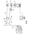
- the systemincludes an MRI-compatible camera (e.g., digital camera capable of acquiring still images, streaming images, etc.) positioned proximate to the head support apparatus, and an MRI-compatible imaging device having one end attached to the targeting frame to provide a local field of view of the burr hole, and an opposite end in communication with the camera.
- the imaging deviceis removably secured to the targeting frame via a bracket, which can include a sleeve configured to slidably receive the imaging device therein.
- the systemalso includes a display output module coupled to the camera for receiving electrical signals therefrom and for displaying images corresponding thereto.
- an MRI-guided interventional systemincludes a head support assembly for immobilizing the head of a patient during an MRI-guided procedure, a targeting frame configured to be secured to the skull of a patient, an MRI-compatible camera, and an MRI-compatible imaging device in communication with the camera.
- the head support assemblyincludes a base configured to be removably secured to a gantry, a head support frame attached to the base, and a longitudinally extending head coil apparatus positioned proximate to the head support frame and configured to surround at least a portion of a patient's head.
- the head coil apparatusincludes a plurality of spaced-apart RF coils.
- the head support frameincludes a pair of elongated arms extending outwardly in adjacent, spaced-apart relationship.
- a pair of head engagement rodsare adjustably associated with the head support frame arms, and are configured to engage a patient's head within the head support frame.
- the targeting frameincludes a cooperating targeting cannula that is configured to guide placement of an interventional device through a burr hole in a patient's skull in vivo.
- the MRI-compatible camerais positioned proximate to the head support assembly.
- the MRI-compatible imaging devicehas one end attached to the targeting frame to provide a local field of view of the burr hole, and an opposite end in communication with the camera.
- the imaging deviceis removably secured to the targeting frame via a bracket, which can include a sleeve configured to slidably receive the imaging device therein.
- the systemalso includes a display output module coupled to the camera for receiving electrical signals therefrom and for displaying images corresponding thereto.
- the head coil apparatushas an open-face, substantially U-shaped configuration with spaced-apart leg portions having free ends, wherein the head coil apparatus is positioned between the head support frame arms such that the leg portion free ends extend upwardly.
- the head coil apparatushas an open-face, substantially U-shaped configuration and comprises a plurality of spaced-apart access windows formed therein. The head coil apparatus can be adjustable along a longitudinal direction relative to the head support frame.
- an MRI-guided interventional systemincludes a head support apparatus for engaging and securing the head of a patient, and a pair of targeting frames configured to be secured to the body of a patient in adjacent, spaced-apart relationship.
- Each targeting frameincludes a cooperating targeting cannula that is configured to guide placement of an interventional device through a burr hole in a patients skull in vivo.
- a pair of MRI-compatible camerasare positioned proximate to the head support apparatus, and are in communication with a pair of MRI-compatible imaging devices.
- Each imaging devicehas one end attached to a respective targeting frame to provide a local field of view of a respective burr hole, and an opposite end in communication with a respective camera.
- the systemalso includes a display output module coupled to the camera for receiving electrical signals therefrom and for displaying images corresponding thereto.
- FIG. 1Ais a block diagram of an MRI-guided interventional system, according to some embodiments of the present invention.
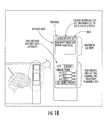
- FIG. 1Billustrates a user interface that displays, and that allows a user to adjust, the trajectory of a targeting cannula, according to some embodiments of the present invention.
- FIG. 2Ais a top perspective view of a burr hole formed in the skull of a patient, and a burr hole ring overlying the burr hole and secured to the skull.
- FIG. 2Bis a top perspective view of a removable centering device positioned on the burr hole ring of FIG. 1 .
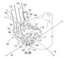
- FIG. 3Ais a perspective view of a trajectory frame utilized in the MRI-guided interventional system, according to some embodiments of the present invention.
- FIGS. 3B-3Eare side view, schematic illustrations of the trajectory frame.
- FIGS. 4-5are partial perspective views of the frame of FIG. 3A illustrating the base of the frame being positioned on the skull of a patient with the centering device of FIG. 2B extending through the patient access aperture.
- FIG. 6illustrates the base secured to the skull of a patient.
- FIG. 7is an enlarged partial perspective view of the base illustrating an attachment location with a pair of adjacent apertures for receiving fasteners therethrough, according to some embodiments of the present invention.
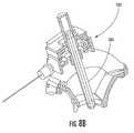
- FIG. 8Ais a perspective view of the frame of FIG. 3A secured to the body (e.g., skull) of a patient, and with the targeting cannula in an extended position.
- bodye.g., skull
- FIG. 8Bis a cut-away perspective view of the frame of FIG. 3A , illustrating a targeting cannula according to some embodiments of the present invention.
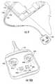
- FIGS. 9 and 10 A- 10 Cillustrate a remote control unit for remotely controlling the positioning actuators of the frame of FIG. 3A , according to some embodiments of the present invention.
- FIG. 11is a perspective view of the base of the frame of FIG. 3A illustrating fiducial markers associated therewith and illustrating an arcuate arm with a thread pattern formed in a surface thereof that is configured to be engaged by a roll axis actuator, according to some embodiments of the present invention.
- FIG. 12is a partial perspective view of the frame of FIG. 3A illustrating a yoke arcuate arm with a thread pattern formed in a surface thereof that is configured to be engaged by a pitch axis actuator, according to some embodiments of the present invention.
- FIGS. 13A-13Billustrate an imaging device mounted to the frame of FIG. 3A so as to view a burr hole, according to some embodiments of the present invention.
- FIG. 14is an enlarged, partial perspective view of the frame of FIG. 3A illustrating the targeting cannula locked in an extended position, according to some embodiments of the present invention.
- FIG. 15is an enlarged, partial perspective view of the frame of FIG. 3A illustrating control cables removably engaged with respective actuators, and illustrating flexible elastomeric collars configured to surround respective actuator free ends and to maintain engagement of the cable ends to a respective actuator free end, according to some embodiments of the present invention.
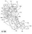
- FIG. 16Ais a partial perspective view of a frame of an MRI-guided interventional system, according to other embodiments of the present invention, and illustrating actuators positioned on a side of the frame and illustrating control cables removably engaged with the respective actuators.
- FIG. 16Bis a partial perspective view of an exemplary prototype actuator illustrating a remote control cable end about to be inserted into a slot in the actuator free end, according to some embodiments of the present invention.
- FIG. 16Cis a partial perspective view of the actuator of FIG. 16B with the remote control cable end inserted into the actuator and with an elastomeric collar engaging the free end of the actuator to prevent the cable from being inadvertently removed from the actuator.
- FIGS. 16D-16Eare partial perspective views of the actuator of FIG. 16C illustrating removal of the elastomeric collar and cable ( FIG. 16E ) from the free end of the actuator.
- FIG. 17illustrates the frame of FIG. 3A secured to the skull of a patient and illustrates a desired trajectory for an interventional device, and also illustrates the actual trajectory of the interventional device as oriented by the frame.
- FIG. 18illustrates the frame of FIG. 17 after reorientation via manipulation of one or more frame actuators such that the actual trajectory is adjusted to be in alignment with the desired trajectory.
- FIG. 19Ais an enlarged, partial perspective view of the frame of FIG. 3A illustrating the X-Y support table, according to some embodiments of the present invention.
- FIG. 19Bschematically illustrates X-Y translation of an X-Y support table and rotational movement of the yoke and platform, according to some embodiments of the present invention.
- FIG. 19Cis partial perspective view of an X-Y support table, according to some embodiments, with elements removed to reveal internal components of an X-direction actuator and Y-direction actuator.
- FIG. 20illustrates a depth stop with a peel-away sheath inserted therein, according to some embodiments of the present invention.
- FIG. 21illustrates an imaging probe inserted within the peel-away sheath of FIG. 20 and with the depth stop advanced to a depth mark on the peel-away sheath, according to some embodiments of the present invention.
- FIG. 22illustrates the depth stop and probe being inserted into the targeting cannula of the frame of FIG. 3A .
- FIG. 23illustrates the probe of FIG. 22 being removed from the peel-away sheath and depth stop.
- FIG. 24illustrates a lead lock secured to the depth stop of FIG. 23 .
- FIG. 25illustrates a lead being inserted through the lead lock of FIG. 24 and through the targeting cannula.
- FIG. 26Ais a perspective view of the frame of FIG. 3A with the lead of FIG. 25 inserted into the brain of a patient and with the peel-away sheath being removed, according to some embodiments of the present invention.
- FIG. 26Bis an enlarged view of the distal end of the peel-away sheath with the distal end of the lead extending therethrough, prior to removal of the sheath.
- FIG. 27illustrates a clamp inserted within and attached to the burr hole ring that is configured to prevent the lead from being retracted from the brain as the frame is removed from the skull of the patient.
- FIGS. 28A-28Gare side view, schematic illustrations of the trajectory frame illustrating exemplary operation of the device for the insertion of interventional devices within the body of a patient via the targeting cannula.
- FIG. 29illustrates a drape configured to be positioned adjacent to a patient and that has a pocket configured to removably receive the remote control unit of FIGS. 9 and 10 A- 10 C.
- FIG. 30illustrates a safety lanyard according to some embodiments of the present invention, wherein the safety lanyard is attached to the remote control unit of FIGS. 9 and 10 A- 10 C and to a rigid object to prevent inadvertent detachment of the control cables.
- FIG. 31is a schematic illustration of a patient positioned within an MRI scanner and a user utilizing a remote control apparatus 400 and display monitors to position a targeting cannula, according to some embodiments of the present invention.
- FIGS. 32A-32Cillustrate a remote control unit for remotely controlling the positioning actuators of the frame of FIG. 3A , according to other embodiments of the present invention.
- FIG. 33is a perspective view of an MRI-guided interventional system including a frame and targeting cannula secured to a patient, and including an imaging device, according to some embodiments of the present invention.
- FIG. 34is a perspective view of an MRI-guided interventional system including a pair of frames and targeting cannulas secured to a patient, each including an imaging device, according to some embodiments of the present invention.
- FIG. 35is a perspective view of an MRI-guided interventional system including a frame and targeting cannula secured to a patient, and including an imaging device, according to other embodiments of the present invention.
- FIG. 36is a schematic illustration of an MRI-guided interventional system including an imaging device, according to some embodiments of the present invention.
- spatially relative termssuch as “under”, “below”, “lower”, “over”, “upper” and the like, may be used herein for ease of description to describe one element or feature's relationship to another element(s) or feature(s) as illustrated in the figures. It will be understood that the spatially relative terms are intended to encompass different orientations of the device in use or operation in addition to the orientation depicted in the figures. For example, if the device in the figures is inverted, elements described as “under” or “beneath” other elements or features would then be oriented “over” the other elements or features. Thus, the exemplary term “under” can encompass both an orientation of “over” and “under”.
- the devicemay be otherwise oriented (rotated 90 degrees or at other orientations) and the spatially relative descriptors used herein interpreted accordingly.
- the terms “upwardly”, “downwardly”, “vertical”, “horizontal” and the likeare used herein for the purpose of explanation only unless specifically indicated otherwise.
- MRI visiblemeans that a device is visible, directly or indirectly, in an MRI image.
- the visibilitymay be indicated by the increased SNR of the MRI signal proximate to the device (the device can act as an MRI receive antenna to collect signal from local tissue) and/or that the device actually generates MRI signal itself, such as via suitable hydro-based coatings and/or fluid (typically aqueous solutions) filled channels or lumens.
- MRI compatiblemeans that a device is safe for use in an MRI environment and/or can operate as intended in an MRI environment, and, as such, if residing within the high-field strength region of the magnetic field, is typically made of a non-ferromagnetic MRI compatible material(s) suitable to reside and/or operate in a high magnetic field environment.
- high-magnetic fieldrefers to field strengths above about 0.5 T, typically above 1.0 T, and more typically between about 1.5 T and 10 T.
- targeting cannularefers to an elongate device, typically having a substantially tubular body that can be oriented to provide positional data relevant to a target treatment site and/or define a desired access path orientation or trajectory. At least portions of a targeting cannula contemplated by embodiments of the invention can be configured to be visible in an MRI image, thereby allowing a clinician to visualize the location and orientation of the targeting cannula in vivo relative to fiducial and/or internal tissue landscape features.
- cannularefers to an elongate device that can be associated with a trajectory frame that attaches to a patient, but does not necessarily enter the body of a patient.
- imaging coilsrefers to a device that is configured to operate as an MRI receive antenna.
- coilwith respect to imaging coils is not limited to a coil shape but is used generically to refer to MRI antenna configurations, loopless, looped, etc., as are known to those of skill in the art.
- fluid-filledmeans that the component includes an amount of the fluid but does not require that the fluid totally, or even substantially, fill the component or a space associated with the component.
- the fluidmay be an aqueous solution, MR contrast agent, or any material that generates MRI signal.
- two degrees of freedommeans that the trajectory frame described herein allows for at least translational (swivel or tilt) and rotational movement over a fixed site, which may be referred to as a Remote Center of Motion (RCM).
- RCMRemote Center of Motion
- Embodiments of the present inventioncan be configured to guide and/or place diagnostic or interventional devices and/or therapies to any desired internal region of the body or object using MRI and/or in an MRI scanner or MRI interventional suite.
- the objectcan be any object, and may be particularly suitable for animal and/or human subjects.
- Some embodimentscan be sized and configured to place implantable DBS leads for brain stimulation, typically deep brain stimulation.
- Some embodimentscan be configured to deliver tools or therapies that stimulate a desired region of the sympathetic nerve chain.
- Other uses inside or outside the braininclude stem cell placement, gene therapy or drug delivery for treating physiological conditions.
- Some embodimentscan be used to treat tumors.
- Some embodimentscan be used for RF ablation, laser ablation, cryogenic ablation, etc.
- the trajectory frame and/or interventional toolscan be configured to facilitate high resolution imaging via integral intrabody imaging coils (receive antennas), and/or the interventional tools can be configured to stimulate local tissue, which can facilitate confirmation of proper location by generating a physiologic feedback (observed physical reaction or via fMRI).
- Some embodimentscan be used to deliver bions, stem cells or other target cells to site-specific regions in the body, such as neurological target and the like.
- the systemsdeliver stem cells and/or other cardio-rebuilding cells or products into cardiac tissue, such as a heart wall via a minimally invasive MRI guided procedure, while the heart is beating (i.e., not requiring a non-beating heart with the patient on a heart-lung machine). Examples of known stimulation treatments and/or target body regions are described in U.S. Pat. Nos.
- some embodiments of the inventionare directed to MRI interventional procedures and provide interventional tools and/or therapies that may be used to locally place interventional tools or therapies in vivo to site-specific regions using an MRI system.
- the interventional toolscan be used to define an MRI-guided trajectory or access path to an in vivo treatment site.
- Some embodiments of the inventionprovide interventional tools that can provide positional data regarding location and orientation of a tool in 3-D space with a visual confirmation on an MRI.
- Embodiments of the inventionmay provide an integrated system that may allow physicians to place interventional devices/leads and/or therapies accurately and in shorter duration procedures over conventional systems (typically under six hours for DBS implantation procedures, such as between about 1-5 hours).
- MRIcan be used to visualize (and/or locate) a therapeutic region of interest inside the brain or other body locations and utilize MRI to visualize (and/or locate) an interventional tool or tools that will be used to deliver therapy and/or to place a chronically implanted device that will deliver therapy. Then, using the three-dimensional data produced by the MRI system regarding the location of the therapeutic region of interest and the location of the interventional tool, the system and/or physician can make positional adjustments to the interventional tool so as to align the trajectory of the interventional tool, so that when inserted into the body, the interventional tool will intersect with the therapeutic region of interest.
- an interventional probecan be advanced, such as through an open lumen inside of the interventional tool, so that the interventional probe follows the trajectory of the interventional tool and proceeds to the therapeutic region of interest.
- the interventional tool and the interventional probemay be part of the same component or structure.
- a sheathmay optionally form the interventional tool or be used with an interventional probe or tool.
- the location of the interventional probe within the therapeutic region of interestcan be visualized on a display or image and allow the physician to either confirm that the probe is properly placed for delivery of the therapy (and/or placement of the implantable device that will deliver the therapy) or determine that the probe is in the incorrect or a non-optimal location. Assuming that the interventional probe is in the proper desired location, the therapy can be delivered and/or the interventional probe can be removed and replaced with a permanently implanted therapeutic device at the same location.
- a new therapeutic target regioncan be determined from the MRI images, and the system can be updated to note the coordinates of the new target region.
- the interventional probeis typically removed (e.g., from the brain) and the interventional tool can be repositioned so that it is aligned with the new target area.
- the interventional probecan be reinserted on a trajectory to intersect with the new target region.
- Exemplary embodimentsare described below with reference to block diagrams and/or flowchart illustrations of methods, apparatus (systems and/or devices) and/or computer program products. It is understood that a block of the block diagrams and/or flowchart illustrations, and combinations of blocks in the block diagrams and/or flowchart illustrations, can be implemented by computer program instructions. These computer program instructions may be provided to a processor of a general purpose computer, special purpose computer, and/or other programmable data processing apparatus to produce a machine, such that the instructions, which execute via the processor of the computer and/or other programmable data processing apparatus, create means (functionality) and/or structure for implementing the functions/acts specified in the block diagrams and/or flowchart block or blocks.
- These computer program instructionsmay also be stored in a computer-readable memory that can direct a computer or other programmable data processing apparatus to function in a particular manner, such that the instructions stored in the computer-readable memory produce an article of manufacture including instructions which implement the functions/acts specified in the block diagrams and/or flowchart block or blocks.
- the computer program instructionsmay also be loaded onto a computer or other programmable data processing apparatus to cause a series of operational steps to be performed on the computer or other programmable apparatus to produce a computer-implemented process such that the instructions which execute on the computer or other programmable apparatus provide steps for implementing the functions/acts specified in the block diagrams and/or flowchart block or blocks.
- exemplary embodimentsmay be implemented in hardware and/or in software (including firmware, resident software, micro-code, etc.). Furthermore, exemplary embodiments may take the form of a computer program product on a computer-usable or computer-readable storage medium having computer-usable or computer-readable program code embodied in the medium for use by or in connection with an instruction execution system.
- a computer-usable or computer-readable mediummay be any medium that can contain, store, communicate, propagate, or transport the program for use by or in connection with the instruction execution system, apparatus, or device.
- the computer-usable or computer-readable mediummay be, for example but not limited to, an electronic, magnetic, optical, electromagnetic, infrared, or semiconductor system, apparatus, device, or propagation medium. More specific examples (a non-exhaustive list) of the computer-readable medium would include the following: an electrical connection having one or more wires, a portable computer diskette, a random access memory (RAM), a read-only memory (ROM), an erasable programmable read-only memory (EPROM or Flash memory), an optical fiber, and a portable compact disc read-only memory (CD-ROM).
- RAMrandom access memory
- ROMread-only memory
- EPROM or Flash memoryerasable programmable read-only memory
- CD-ROMportable compact disc read-only memory
- the computer-usable or computer-readable mediumcould even be paper or another suitable medium upon which the program is printed, as the program can be electronically captured, via, for instance, optical scanning of the paper or other medium, then compiled, interpreted, or otherwise processed in a suitable manner, if necessary, and then stored in a computer memory.
- Computer program code for carrying out operations of data processing systems discussed hereinmay be written in a high-level programming language, such as Java, AJAX (Asynchronous JavaScript), C, and/or C++, for development convenience.
- computer program code for carrying out operations of exemplary embodimentsmay also be written in other programming languages, such as, but not limited to, interpreted languages.
- Some modules or routinesmay be written in assembly language or even micro-code to enhance performance and/or memory usage.
- embodimentsare not limited to a particular programming language. It will be further appreciated that the functionality of any or all of the program modules may also be implemented using discrete hardware components, one or more application specific integrated circuits (ASICs), or a programmed digital signal processor or microcontroller.
- ASICsapplication specific integrated circuits
- FIG. 1Ais a block diagram of an MRI-guided interventional system 50 , according to some embodiments of the present invention.
- the illustrated system 50includes an MRI scanner 75 , a trajectory frame 100 attached to the body of a patient positioned within a magnetic field of the MRI scanner 75 , a remote control unit 400 , a trajectory guide software module 300 , and a clinician display 500 .
- the trajectory frame 100supports a targeting cannula through which various interventional devices may be inserted into the body of a patient.
- the frame 100is adjustable such that the targeting cannula is rotatable about a pitch axis, about a roll axis, and such that the targeting cannula can translate in X-Y directions.
- the frame 100may be attached to the body of a patient directly or indirectly and may be configured to be attached to various parts of the body.
- a remote control unit 400is provided to allow a user to remotely adjust the position of the targeting cannula.
- the trajectory guide software module 300allows a user to define and visualize, via display 500 , a desired trajectory (D, FIGS. 17-18 ) into the body of a patient of an interventional device extending through the targeting cannula.
- the trajectory guide software module 300also allows the user to visualize and display, via display 500 , an actual trajectory (A, FIG. 17 ) into the body of an interventional device extending through the targeting cannula.
- the trajectory guide software module 300displays to the user the necessary positional adjustments (e.g., pitch axis rotation, roll axis rotation, X-Y translation) needed to align the actual trajectory of the targeting cannula with the desired trajectory path ( FIG. 1B ).
- the usercan view, via display 500 , the actual trajectory changing as he/she adjusts the position of the targeting cannula.
- the trajectory guide software module 300is configured to indicate and display when an actual trajectory is aligned with a desired trajectory.
- FIG. 2Aillustrates a burr hole 10 formed in the skull S of a patient.
- a burr hole ring 12overlies the burr hole 10 and is secured to the skull S.
- the illustrated burr hole ring 12has a pair of ears 14 , each configured to receive a respective fastener (e.g., screw) therethrough for securing the burr hole ring 12 to the skull.
- the burr hole ring 12is secured to the skull S via screws 16 .
- FIG. 2Billustrates a removable centering device 18 positioned on the burr hole ring 12 .
- the centering device 18includes cut out portions 20 that fit over the ears 14 of the burr hole ring 12 .
- the function of the centering device 18is to facilitate centering a trajectory frame 100 , described below, over the burr hole 10 . After the frame 100 is attached to the skull of a patient, the centering device 18 is removed.
- a trajectory frame 100 with a targeting cannula 200 associated therewithis illustrated.
- the trajectory frame 100allows for the adjustability (typically at least two degrees of freedom, including rotational and translational) and calibration/fixation of the trajectory of the targeting cannula 200 and/or probe or tool inserted through the targeting cannula 200 .
- the targeting cannula 200includes an axially-extending guide bore (not shown) therethrough that is configured to guide the desired therapeutic or diagnostic tool, e.g., intra-brain placement of a stimulation lead (or other type of device) in vivo, as will be described below. Intra-brain placement of devices may include chronically placed devices and acutely placed devices.
- the trajectory frame 100may include fiducial markers 117 that can be detected in an MRI to facilitate registration of position in an image.
- the illustrated trajectory frame 100is configured to be mounted to a patient's skull around a burr hole ring ( 12 , FIG. 1 ) and over a burr hole ( 10 , FIG. 1 ), to provide a stable platform for advancing surgical devices, leads, etc. in the brain.
- the frame 100includes a base 110 , a yoke, 120 , a platform 130 , and a plurality of actuators 140 a - 140 d .
- the base 110has a patient access aperture 112 formed therein, as illustrated.
- the base 110is configured to be secured (directly or indirectly) to the skull of a patient such that the patient access aperture 112 overlies the burr hole 10 in the patient skull.
- the patient access aperture 112is centered over the burr hole 10 via the removable centering device 18 .
- the yoke 120is movably mounted to the base 110 and is rotatable about a roll axis RA.
- a roll actuator 140 ais operably connected to the yoke 120 and is configured to rotate the yoke 120 about the roil axis RA, as will be described in detail below.
- the yoke 120has a range of motion about the roll axis RA of about seventy degrees (70°). However, other ranges, greater and lesser than 70°, are possible, e.g., any suitable angle typically between about 10°-90°, 30°-90°, etc.
- the illustrated platform 130is movably mounted to the yoke 120 and is rotatable about a pitch axis PA.
- the platform 130has a range of motion about the pitch axis PA of about seventy degrees (70°).
- 70°seventy degrees
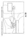
- FIGS. 3B-3Eare side view, schematic illustrations of the trajectory frame being secured to the skull of a patient.
- FIG. 3Billustrates use of the centering device 18 to align the frame 100 relative to the burr hole 10 .
- the frame 100is secured to the skull with fasteners and such that the patient access aperture 112 in the base 110 is centered around the centering device 18 .
- the yoke 120is rotated out of the way such that the centering device 18 can be removed.
- the targeting cannula 200is moved to an extended position and locked in the extended position via prongs 208 .
- the platform 130includes an X-Y support table 132 that is movably mounted to the platform 130 .
- the X-Y support table 132is configured to move in an X-direction and Y-direction relative to the platform 130 .
- An X-direction actuator 140 cis operably connected to the platform 130 and is configured to move the X-Y support table 132 in the X-direction.
- a Y-direction actuator 140 dis operably connected to the platform 130 and is configured to move the X-Y support table 132 in the Y-direction.
- a pitch actuator 140 bis operably connected to the platform 130 and is configured to rotate the platform 130 about the pitch axis PA, as will be described in detail below.
- the actuators 140 a - 140 dare configured to translate and/or rotate the frame.
- the targeting cannula 200is configured to translate in response to translational movement of the X-Y support table 132 and to rotate in response to rotational movement of the yoke 120 and platform 130 to define different axial intrabody trajectories extending through the patient access aperture 112 in the frame base 110 .
- the actuators 140 a - 140 dmay be manually-operated devices, such as thumbscrews, in some embodiments.
- the thumbscrewscan be mounted on the frame 100 or may reside remotely from the frame 100 .
- a usermay turn the actuators 140 a - 140 d by hand to adjust the position of the frame 100 and, thereby, a trajectory of the targeting cannula 200 .
- the actuators 140 a - 140 dare operably connected to a remote control unit 400 ( FIGS. 9-10 ) via a respective plurality of non-ferromagnetic, flexible drive shafts or control cables 150 a - 150 d .
- the remote control unit 400includes a plurality of position controls 402 a - 402 d , and each cable 150 a - 150 d is operably connected to a respective position control 402 a - 402 d and to a respective actuator 140 a - 140 d . Movement of a position control 402 a - 402 d operates a respective actuator 140 a - 140 d via a respective control cable 150 a - 150 d , as will be described below.
- the cables 150 a - 150 dmay extend a suitable distance (e.g., between about 1-4 feet, etc.) to allow a clinician to adjust the settings on the trajectory frame 100 without moving a patient and from a position outside the bore of a magnet (where such magnet type is used) associated with an MRI scanner.
- a suitable distancee.g., between about 1-4 feet, etc.
- the base 110includes a plurality of locations 112 for attaching the base 110 to a skull of a patient via fasteners.
- Each locationmay include two or more adjacent apertures 114 .
- Each aperture 114is configured to receive a fastener (e.g., a screw, rod, pin, etc.) therethrough that is configured to secure the base 110 to the skull of a patient.
- a fastenere.g., a screw, rod, pin, etc.
- the base 110also includes MRI-visible fiducial markers 117 that allow the location/orientation of the frame 100 to be determined within an MRI image during an MRI-guided procedure.
- the fiducial markers 117have a torus or “doughnut” shape and are spaced apart.
- fiducial markers having various shapes and positioned at various locations on the frame 100may be utilized.
- the base 110also includes a pair of spaced apart arcuate arms 116 , as illustrated in FIG. 11 .
- the yoke 120is pivotally attached to pivot points 113 for rotation about the roll axis RA.
- the yoke 120engages and moves along the base arcuate arms 116 when rotated about the roll axis RA.
- one of the base arcuate arms 116includes a thread pattern 118 formed in (e.g., embossed within, machined within, etc.) a surface 116 a thereof.
- both arms 116may include respective thread patterns.
- the roll actuator 140 aincludes a rotatable worm 142 with teeth that are configured to engage the thread pattern 118 , as illustrated in FIG. 5 .
- the yoke 120includes a pair of spaced apart upwardly extending, arcuate arms 122 .
- the platform 130engages and moves along the yoke arcuate arms 122 when rotated about the pitch axis PA.
- one of the yoke arcuate arms 122includes a thread pattern 124 formed in (e.g., embossed within, machined within, etc.) a surface 122 a thereof.
- both arms 122may include respective thread patterns.
- the pitch actuator 140 bincludes a rotatable worm 146 with teeth 148 that are configured to engage the thread pattern 124 .
- the teeth 148travel along the thread pattern 124 in the arcuate arm surface 122 a . Because the base 110 is fixed to a patient's skull, rotation of the pitch actuator worm 146 causes the platform 130 to rotate about the pitch axis PA relative to the fixed base 110 .
- the X-Y support table 132includes a moving plate 134 that moves in both the X-direction and Y-direction.
- the X-direction actuator 140 cwhen rotated, causes translational movement of the moving plate 134 along the X-axis. For example, clockwise rotation of the X-direction actuator 140 c causes movement toward the “ ⁇ X direction (i.e., to the left) in FIG. 19A ; and counterclockwise rotation of the X-direction actuator 140 c causes movement along the +X direction (i.e., to the right) in FIG. 19A , etc.
- the Y-direction actuator 140 dwhen rotated, causes translational movement of the moving plate 134 along the Y-axis. For example, clockwise rotation of the Y-direction actuator 140 d causes movement along the ⁇ Y direction (i.e., out of the paper) in FIG. 19A ; and clockwise rotation of the Y-direction actuator 140 d causes movement along the +Y direction (i.e., into the paper) in FIG. 19A .
- graduation scales 136 , 137are provided on the platform adjacent the moving plate 134 .
- the moving plate 134includes a pair of marks or indicators 138 that provide visual indication of X-Y movement of the moving plate 134 .
- FIG. 19Billustrates X-Y translation of an X-Y support table 132 , according to some embodiments of the present invention.
- FIG. 19Cis partial perspective view of an X-Y support table, according to some embodiments, with elements removed to reveal internal components of an X-direction actuator 140 c and Y-direction actuator 140 d.
- the roll actuator 140 a , pitch actuator 140 b , X-direction actuator 140 c , and Y-direction actuator 140 deach extend outwardly from the frame 100 along the same direction (e.g., upwardly from the platform 130 ).
- This configurationfacilitates easy connection of the control cables 150 a - 150 d to the actuators 140 a - 140 d (where used) and also facilitates bundling of the cables 150 a - 150 d to reduce clutter or provide ease of handling and set-up.
- Embodiments of the present inventionare not limited to the illustrated embodiment, however.
- the actuators 140 a - 140 dmay extend in various directions and these directions may be different from each other.
- the actuators 140 a - 140 dmay extend along the same direction from the frame, but in a different direction than that illustrated in FIG. 3A .
- FIG. 16illustrates an embodiment where the actuators 140 a - 140 d extend from a common side of the platform 130 .
- the remote control unit 400 of the illustrated system 50includes a plurality of manually-operable position controls 402 a - 402 d .
- the control unit 400includes a roll adjustment control 402 a , a pitch adjustment control 402 b , an X-direction adjustment control 402 c , and a Y-direction adjustment control 402 d .
- a roll control cable 150 ais operably connected to the roll adjustment control 402 a and to the roll actuator 140 a such that movement of the roll adjustment control 402 a operates the roll actuator 140 a via the roll control cable 150 a .
- a pitch control cable 150 bis operably connected to the pitch adjustment control 402 b and to the pitch actuator 140 b such that movement of the pitch adjustment control 402 b operates the pitch actuator 140 b via the pitch control cable 150 b .
- An X-direction control cable 150 cis operably connected to the X-direction control 402 c and to the X-direction actuator 140 c such that movement of the X-direction adjustment control 402 c operates the X-direction actuator 140 c via the X-direction control cable 150 c .
- a Y-direction control cable 150 dis operably connected to the Y-direction control 402 d and to the Y-direction actuator 140 d such that movement of the Y direction adjustment control 402 d operates the Y-direction actuator 140 d via the Y-direction control cable 150 d.
- each of the position controls 402 a - 402 dis a thumbwheel control that can be rotated by a user's finger in clockwise and counterclockwise directions. Rotation of each thumbwheel 402 a - 402 d by a user causes corresponding axial rotation of a respective control cable 150 a - 150 d and corresponding axial rotation of a respective actuator 140 a - 140 d.
- FIG. 10Billustrates position controls, according to additional embodiments of the present invention, that utilize two thumbwheels.
- One thumbwheel 402 a ′is for “fine” adjustments; the other thumbwheel 402 a ′′ is for “gross” adjustments.
- the amount of fine and gross adjustmentis correlated to the diameter of each thumbwheel, as would be understood by one skilled in the art.
- FIG. 10Cillustrates a position control 402 a ′′′, according to additional embodiments of the present invention, that indicates incremental X-Y variable markings.
- locking mechanisms 404 a - 404 care associated with the thumbwheels 402 a - 402 d and prevent user rotation thereof when in a locked position.
- a locking mechanism 404 ais operably associated with the roll adjustment control 402 a and is configured to prevent rotation thereof by a user when in a “locked” position.
- Locking mechanism 404 bis operably associated with pitch adjustment control 402 b and is configured to prevent rotation thereof by a user when in a “locked” position.
- Locking mechanism 404 cis operably associated with X-direction control 402 c and Y-direction control 402 d and is configured to prevent rotation of X-direction control 402 c and Y-direction control 402 d by a user when in a “locked” position.
- Each control cable 150 a - 150 dcan have a geometrically shaped rigid end 151 a - 151 d that is configured to removably engage a free end of a respective actuator 140 a - 140 d .
- the respective free ends 141 a - 141 d of the actuators 140 a - 140 dmay have a slot 143 formed therein that is configured to removably receive a respective cable end.
- Exemplary cable end shapesinclude, but are not limited to, “L” shapes, “U” shapes, square shapes, rectangular shapes, oval/circular shapes, and other polygonal shapes.
- Each cable endhas sufficient rigidity such that axial rotation of the cable causes the cable free end to impart rotational motion to a respective actuator.
- FIG. 15illustrates the free end of cable 150 b having a connector 151 b with a geometric shape attached thereto that is configured to matingly engage a respective slot 143 in actuator 140 b , according to other embodiments of the present invention.
- the free end of an actuator 140 a - 140 dmay be configured to receive only a specific one of the control cables 150 a - 150 d .
- the connector 151 bmay not fit within the slots 143 of any of the other actuators. As such, a control cable cannot be inadvertently connected to the wrong actuator.
- the roll adjustment actuator free end 141 amay be configured to only receive the free end 151 a of the control cable 150 a associated with the roll control 402 a .
- the pitch adjustment actuator free end 141 bmay be configured to only receive the free end 151 b of the control cable 150 b associated with the pitch control 402 b.
- Each control cable 150 a - 150 dalso has a flexible elastomeric (e.g., silicone, rubber, etc.) collar 154 a - 154 d that is configured to surround a respective actuator 140 a - 140 d and maintain engagement of the respective cable end 151 a - 151 d within the respective actuator.
- Each elastomeric collar 154 a - 154 dis configured to prevent removal of a cable by a user, for example, as a result of inadvertent tugging on the cable by a user, or by movement of the remote control unit 400 .
- each of the illustrated collars 154 a - 154 dcan be rolled or folded back then released to cover and conformably compress against an actuator to hold the end of a respective cable in position. Each collar 154 a - 154 d can then be pushed back to easily release the cable from the actuator.
- each actuator 140 a - 140 dhas a circumferential groove 145 configured to receive a corresponding circumferential ridge 156 of a collar 154 a - 154 d in mating relation therewith.
- FIG. 16Billustrates remote control cable end 151 a about to be inserted into slot 143 in the actuator free end 141 a .
- the cable end 151 ais inserted into the slot 143 and then the elastomeric collar 154 a is fitted around the actuator 140 a such that the circumferential ridge 156 engages the circumferential actuator groove 145 , as illustrated in FIG. 16C .
- the collarsnuggly fits the actuator 140 a and retains the cable end 151 a within slot 143 .
- the circumferential ridge 156is pulled out of the groove 145 and the collar 154 a is rolled back on itself as illustrated in FIGS. 16D-16E .
- Embodiments of the present inventionare not limited to the illustrated elastomeric collars 154 a - 154 d .
- Other ways of retaining the cable ends 151 a - 151 d within respective actuators 140 a - 140 dmay be utilized without limitation.
- the actuators 140 a - 140 dare color coded such that each actuator has a different respective color for easy identification by a user.
- the roll actuator 140 amay be colored red and the pitch actuator 140 b may be colored yellow such that a user can easily identify the two respective actuators when positioning the frame 100 .
- the elastomeric collars 154 a - 154 dmay also be color coded so as to match the color of a respective actuator 140 a - 140 d .
- the cable ends 151 a - 151 dmay also be color coded so as to match the color of a respective actuator 140 a - 140 d.
- control cables 150 a - 150 dare formed of NITINOL or other MR-compatible materials.
- One or more portions of the frame 100 and the targeting cannula 200may also be formed of NITINOL or other MR-compatible (non-paramagnetic) materials, such as plastics and other polymeric materials.
- FIG. 31illustrates a patient positioned within an MRI scanner and a user utilizing the remote control apparatus 400 and display monitors to adjust the trajectory a targeting cannula, according to some embodiments of the present invention.
- FIGS. 32A-32Cillustrate a remote control unit 800 for remotely controlling the positioning actuators of the frame of FIG. 3A , according to other embodiments of the present invention.
- the illustrated remote control unit 800includes a separate, multi-rod control device 802 a - 802 d for each respective actuator 140 a - 140 d .
- Each of the control devices 802 a - 802 dcan be identical in structure and, as such, only one will be described in detail hereinafter. However, each control device 802 a - 802 d may be color coded with a color different from the other control devices 802 a - 802 d , and each control device 802 a - 802 d may have different lengths, shapes or sizes for ease of assembly and/or operation. Moreover, each control device 802 a - 802 d may be color coded so as to match the color of a respective actuator 140 a - 140 d.
- Each control device 802 a - 802 dincludes a pair of elongated rods 804 , 806 (e.g., solid, MRI-compatible rods) joined at respective ends via a flexible member such as a cable 807 , as illustrated.
- the rods 804 , 806may be formed of wood, polymeric material, or other suitable relatively lightweight MRI-compatible material.
- the rods 804 , 806are not required to be solid.
- the cable 807is relatively short in length relative to the length of rods 804 , 806 and serves as a universal joint to allow the two rods 804 , 806 to rotate even when oriented transverse to each other.
- the cable 807may be between about one quarter inch and about one inch (0.25′′-1′′) in length.
- embodiments of the present inventionare not limited to this range for the length of cable 807 ; cable 807 may have other lengths.
- the cable 807is an MRI-compatible cable (e.g., NITINOL, etc.).
- the distal end 804 b of rod 804is joined to the proximal end 806 a of rod 806 via cable 807 .
- the cable 807may be joined to rods 804 , 806 in any of various ways including, but not limited to, via adhesives, via fasteners, via threaded connections, etc.
- the proximal end 804 a of rod 804includes an endcap 808 secured thereto.
- the endcap 808may be formed from tactile material to facilitate rotation of rod 804 by a user.
- a knob or other device that facilitates rotationmay be secured to the proximal end of rod 804 in lieu of endcap 808 , in other embodiments.
- a userrotates the proximal end 804 a of rod 804 in a clockwise or counterclockwise direction to correspondingly rotate actuator 140 a.
- the distal end 806 b of rod 806is joined to actuator 140 a via a flexible member such as a cable 810 , as illustrated.
- the cable 810is relatively short in length relative to the length of rod 806 and serves as a universal joint to allow rod 806 to rotate even when oriented transverse to actuator 140 a .
- the cable 810is an MRI-compatible cable.
- the cable 810may be between about one half inch and about one and one half inch (0.5′′-1.5′′) in length.
- embodiments of the present inventionare not limited to this range for the length of cable 810 ; cable 810 may have other lengths.
- Cable 810may be joined to rod 806 in any of various ways including, but not limited to, via adhesives, via fasteners, via threaded connections, etc.
- the free end of cable 810may have a rigid, geometrical shape, as described above with respect to the embodiments of cables 150 a - 150 d , and may be configured to engage a slot within the actuator 140 a , as described above.
- An elastomeric collar, as described above with respect to FIGS. 16A-16Emay or may not be necessary to retain the free end of cable 810 within actuator 140 a . In the illustrated embodiment, an elastomeric collar is not utilized. When used, an elastomeric collar can also be color coded to the actuator and/or control device rods 804 , 806 .
- control devices 802 a - 802 dare supported by a pair of spaced apart separator devices 812 .
- Each separator device 812includes a plurality of substantially parallel, spaced apart bores passing therethrough that are configured to receive each of the rods 804 for the respective control devices 802 a - 802 d .
- the separator devices 812are configured to maintain the rods 804 in substantially parallel, spaced apart relationship, as illustrated. In the illustrated embodiment, only rods 804 pass through the two separator devices 812 .
- embodiments of the present inventionare not limited to the illustrated use, configuration, location, or number of separation devices 812 .
- each control device 802 a - 802 dmay include three or more spaced apart rods (not shown), or only a single rod (not shown).
- other types of devicesmay be utilized without limitation.
- an elongated tubular member 204extends through the platform 130 and yoke 120 and is secured to the X-Y support table 132 .
- the targeting cannula 200is slidably secured within the tubular member 204 and is movable between extended and retracted positions.
- FIGS. 3A-3D and 4 - 6illustrate the targeting cannula 200 in a retracted position above the burr hole 10 and
- FIGS. 3E and 8Aillustrate the targeting cannula 200 in an extended position.
- the tubular member 204is configured to lock the targeting cannula 200 in an extended position and in a retracted position, as illustrated in FIG. 14 .
- the tubular member 204has a pair of radially opposed elongated, axial-extending slots 206 , as illustrated.
- the ends 206 a , 206 b of each slot 206include a transverse portion 207 that is configured to retain the targeting cannula 200 in respective extended and retracted positions.
- the targeting cannula 200includes a respective pair of radially extending prongs 208 , as illustrated. Each prong 208 cooperates with a respective slot 206 .
- the targeting cannula 200is moved upwardly to the retracted position, the targeting cannula 200 is rotated slightly (or the tubular member 204 is rotated slightly) such that prongs 208 each engage a respective transverse portion 207 .
- the targeting cannula 200When so engaged, the targeting cannula 200 is retained in the retracted position. When the targeting cannula 200 is moved downwardly to the extended position, the targeting cannula 200 is rotated slightly (or the tubular member 204 is rotated slightly) such that prongs 208 each engage a respective transverse portion 207 . When so engaged, the targeting cannula 200 is retained in the extended position.
- Embodiments of the present inventionare not limited to the illustrated configuration or number of slots 206 in the tubular member 204 or to the number of prongs 208 extending from the targeting cannula 200 .
- the targeting cannula 200may have a single prong 208 that is configured to cooperate with a respective single slot 206 in the tubular member 204 .
- slot 206may have a different configuration than illustrated.
- a depth stop 210 with a removable sheath 212 inserted and secured thereinis illustrated.
- the illustrated depth stop 210has a generally cylindrical configuration with opposite proximal and distal ends 210 a , 210 b and is adapted to be removably secured within the proximal end 204 a of the tubular member 204 .
- the depth stop 210is configured to limit a distance that the sheath 212 extends into the body of a patient when the depth stop is inserted within the tubular member 204 .
- the sheath 212is configured to receive and guide an elongated interventional device therethrough, as will be described below.
- the sheath 212includes opposing tabs 214 a , 214 b that, when pulled apart, cause the sheath 212 to peel away for removal from the targeting cannula 200 .
- the distal end 210 b of the depth stop 210Prior to insertion within the tubular member 204 , the distal end 210 b of the depth stop 210 is positioned adjacent to a mark 215 on the removable sheath 212 , as illustrated in FIG. 21 .
- Locking screw 216is then tightened to prevent axial movement of the sheath 212 relative to the depth stop 210 .
- An elongate location verification probe 217such as an imaging probe, is then inserted within the sheath 212 as illustrated in FIG. 21 .
- the opposing tabs 214 a , 214 b of the sheathare pulled apart slightly, and the depth stop 210 , sheath 212 and imaging probe 217 are inserted into the proximal end 204 a of tubular member 204 .
- the sheath 212 and imaging probe 217pass through the axial bore of the targeting cannula 200 .
- the imaging probe 217is then utilized to verify that the distal end 212 b of the sheath 212 is positioned at the correct location within the body of a patient. Upon verifying that the sheath 212 is accurately positioned, the imaging probe 217 is removed ( FIG. 23 ).
- the probe 217 extending through the targeting cannula guide borecan include at least one electrode (which may include a coil winding) on a distal tip portion thereof.
- the electrodecan be a recording and/or stimulating electrode.
- the electrodecan be configured to deliver test voltages for physiologic confirmation of location/efficacy that can be done by fMRI or by feedback from a non-anesthetized patient.
- a patientcan be stimulated with an interventional probe (the stimulation may be via a transducer on a distal tip portion of the probe), to help confirm that the interventional probe is in the correct location (i.e., confirm proper location via anatomical as well as provide physiologic information and feedback).
- the physiciancan monitor for a physiologic response from the patient that can be observed either directly from the patient as a physical response or via an fMRI-visible response.
- the elongate probe 217can be MRI-visible and may optionally be configured to define an MRI antenna.
- the system 50can be configured to allow for real-time tracking under MRI, with an SNR imaging improvement in a diameter of at least 1-10 mm surrounding the probe.
- a locking mechanism 220is removably secured to the proximal end 210 a of the depth stop 210 .
- the locking mechanism 202includes opposing axially extending slots 221 , as illustrated. The portions of the sheath 212 that have been peeled away extend through these slots as illustrated.
- the locking mechanism 220is secured to the depth stop/tubular member via locking screw 222 .
- the targeting cannula 200is now ready to receive an interventional device therein.
- an interventional device 230such as a brain stimulation lead, is inserted into the locking mechanism and through the removable sheath 212 .
- a locking screw 224is tightened to secure the interventional device 230 and prevent axial movement thereof.
- the targeting cannula 200can be MRI-visible.
- the cannula 200may optionally comprise a plurality of spaced apart microcoils configured to provide data used to provide 3-D dimensional data in MRI 3-D space, such as a trajectory, or 3-D spatial coordinates of position of the cannula 200 .
- the microcoilscan each provide data that can be correlated to a three-dimensional (X, Y, Z) position in 3-D space in the body.
- the microcoilscan be in communication with the MRI scanner, and tracking sequences can be generated and data from one or more of the MRI scanner channels can be used to define positional 3-D positional data and a trajectory thereof.
- the progress of the cannula 200 and/or interventional probe 230 or other devicemay optionally be tracked in substantially real-time as it advances to the target via the coils (similar ones of which may also or alternatively be on or in the probe or other device) and/or antenna.
- realtime trackingmay not be desired in some embodiments.
- the cannula 200can include at least one axially extending fluid-filled hollow lumen ( FIG. 8B ) or closed channel with fluid that can generate MRI signal that can be detected by an MRI scanner and/or by an internal MRI antenna incorporated on and/or into the cannula 200 that can increase the SNR of the fluid to increase its visibility in an MRI.
- the fluidmay be an aqueous solution (able to resonate at the proton frequency).
- the cannula 200can include an axially extending, relatively thin segment, which creates a high contrast MRI image (a segment filled with water or other suitable contrast solution filled section/lumen).
- the thickness of the segmentmay be between about 0.25-15 mm (and the segment can have a tubular shape with a diameter or may define another cross-sectional shape such as a square section).
- the cannula 200may include MRI imaging coils to increase the signal from the high contrast fluid. See, e.g., co-pending U.S. patent application Ser. No. 12/066,862, which is incorporated here by reference in its entirety.
- the interventional device 230is positioned at the desired location within the body of a patient.
- the removable sheath 212is then completely removed by pulling apart the opposing tabs 214 a , 214 b .
- a clamp 240( FIG. 27 ) is inserted within the burr hole ring 12 that grips the interventional device 230 to prevent inadvertent removal of the interventional device 230 from the body of the patient.
- the clamp 240is secured to the burr hole ring 12 .
- the frame 100can then be removed from the body of the patient, leaving behind only the interventional device 230 that has been inserted into the patient body.
- FIGS. 28A-28Gare side view, schematic illustrations of the trajectory frame 100 illustrating an exemplary series of operations for the insertion of interventional devices within the body of a patient via the targeting cannula 200 .
- the locking mechanism 220 , depth stop 210 , and removable sheath 212are positioned within the targeting cannula 200 .
- an interventional devicee.g., lead 230
- the locking mechanism 220secures the lead against axial movement ( FIG. 28C ).
- the targeting cannula 200is then retracted ( FIGS. 28D-28E ).
- the locking mechanism 220is unlocked ( FIG. 28F ) and the frame 100 is removed from the skull of the patient ( FIG. 28G ).
- an imaging devicee.g., a fiber scope/imaging device with visual access to the burr hole 10 and/or trajectory frame 100 in communication with a camera and display in a clinician workstation
- 500 for viewing the burr hole 10is removably secured to the frame 100 or to the targeting cannula tubular member 204 via a bracket 502 .
- a bracket 502is secured to the targeting cannula tubular member 204 .
- the illustrated bracket 502is configured to adjustably slide axially along the tubular member 204 for positioning.
- the illustrated bracket 502includes a sleeve 504 that is configured to slidably receive an imaging device 500 therein.
- Threaded locking device 506is configured to secure the imaging device 500 in position within the sleeve 504 for positioning of the imaging device 500 relative to the body of a patient.
- a clinicianviews images captured by the imaging device 500 via a monitor, as illustrated in FIG. 13B .
- a sterile drape 600is provided for holding the remote control unit 400 .
- the drape 600is configured to be positioned near the body of a patient and includes a pocket 602 configured to removably receive the remote control unit 400 therein.
- the drape 600also includes an aperture 604 through which the cables 150 a - 150 b extend from the remote control unit 400 to the frame 100 .
- the drape 600is attached to the magnet housing M of an MRI scanner system.
- control cables 150 a - 150 dare configured to have a limited length. Accordingly, as illustrated in FIG. 30 , a safety lanyard 700 may be attached to the remote control unit 400 and to a rigid object to prevent inadvertent detachment of the control cables 150 a - 150 d from the frame actuators 140 a - 140 d caused by moving the remote control unit 400 too far from the frame 100 .
- MR imagesare obtained of the patient's head that visualize the patient's skull, brain, fiducial markers and ROI (region of interest or target therapeutic site).
- the MR imagescan include volumetric high-resolution images of the brain.
- certain known anatomical landmarkscan be used, i.e., reference to the AC, PC and MCP points (brain atlases give the location of different anatomies in the brain with respect to these point) and other anatomical landmarks.
- the location of the burr hole 10may optionally be determined manually by placing fiducial markers on the surface of the head or programmatically by projecting the location in an image.
- Images in the planned plane of trajectoryare obtained to confirm that the trajectory is viable, i.e., that no complications with anatomically sensitive areas should occur.
- the patient's skullis optically or manually marked in one or more desired locations to drill the burr hole.
- the burr hole 10is drilled and a burr hole ring 12 is affixed to the skull overlying the burr hole.
- the trajectory frame 100is then fixed to the skull of the patient and the targeting cannula 200 is properly fitted thereto.
- a localization scanis obtained to determine/register the location of the targeting cannula 200 , in direct orientation of the trajectory frame 100 .
- the settings to which the trajectory frame 100 should be adjustedare electronically determined so that the targeting cannula 200 is in the desired trajectory plane.
- Frame adjustment calculationsare provided to a clinician who can manually or electronically adjust the orientation of the frame 100 .
- the desired trajectory planeis confirmed by imaging in one or more planes orthogonal to the desired trajectory plane.
- the multipurpose probe 217 and delivery sheath 212are advanced through the targeting cannula 200 .
- the advancement of the probe 217is monitored by imaging to verify that the probe will reach the target accurately. If the probe 217 and delivery sheath 212 are at the desired target, the sheath is left in place and the probe 217 is removed. The sheath 212 will now act as the delivery cannula for the implantable lead 230 .
- the probe 217 and delivery sheath 212are not at the desired/optimal location, a decision is made as to where the probe 217 and delivery sheath 212 need to be.
- the trajectory frame 100is adjusted accordingly via the actuators 140 a - 140 d and the probe 217 and delivery sheath 212 are re-advanced into the brain.
- the probe 217 and delivery sheath 212are at the desired location, the probe 217 is removed and the delivery sheath is left in place.
- the lead 230is then advanced to the target location using the sheath 212 as a guide. The location of the lead is confirmed by reviewing an image, acoustic recording and/or stimulation.
- the sheath 212is then removed, leaving the lead in place.
- embodiments of the inventioncan provide an integrated system 50 that may allow the physician to place the interventional device/leads accurately and in short duration of time.
- the trajectory frameis oriented such that the interventional device advanced using the trajectory frame follows the desired trajectory and reaches the target as planned in preoperative setup imaging plans.
- the system 50can employ hardware and software components to facilitate an automated or semiautomated operation to carry out this objective.
- the illustrated MRI-guided interventional system 50 ′includes a trajectory frame 100 having a targeting cannula 200 associated therewith, as described above.
- the frame 100is secured to the skull of a patient, as described above.
- the illustrated system 50 ′includes an imaging device 500 secured to the frame 100 and coupled to an MRI-compatible camera 900 positioned proximate to a patient.
- the imaging device 500includes a lens (not shown), and an optical fiber cable that includes one or more optical fibers for providing light from a light source 950 , and at least about five thousand (5,000) optical fibers for providing an image to camera 900 .
- the lensis in optical communication with the optical fibers and facilitates obtaining a focused image, as would be understood by those skilled in the art.
- the imaging device 500is secured to the frame 100 and, more specifically, as shown in FIG. 13A , to the targeting cannula tubular member 204 ( FIG. 3A ) via a bracket 502 positioned such that the imaging device 500 has a local, small field of view visual access to a burr hole 10 in the skull of a patient.
- the illustrated bracket 502is configured to adjustably rotate around the tubular member 204 for positioning.
- the illustrated bracket 502includes a sleeve 604 that is configured to slidably receive the imaging device 500 therein. Threaded locking device 506 is configured to secure the imaging device 500 in position within the sleeve 504 for positioning of the imaging device 500 relative to the body of a patient.
- the illustrated system 50 ′also includes a head support assembly 910 with a head coil apparatus 930 attached thereto.
- the illustrated head support assembly 910includes a base 912 and a head support frame 914 .
- the base 912 and head support frame 914may be an integral unit, or may be separate components.
- the base 912is secured to the gantry 916 associated with an MRI scanner 918 .
- Embodiments of the present inventionare not limited to the illustrated base 912 , or to the illustrated head coil 930 .
- the illustrated head support frame 914includes a pair of elongated arms 918 that extend outwardly from the base 912 in adjacent, spaced-apart relationship to form an area for receiving the head of a patient.
- Head support frames according to embodiments of the present inventionmay have various structural configurations, without limitation, and are not limited to the illustrated embodiment.
- the illustrated head support assembly 910includes a head coil apparatus 930 that is positioned proximate to the head support frame 914 .
- the head coil apparatus 930has a substantially open-face, U-shaped configuration with spaced-apart leg portions 930 a , 930 b having free ends.
- the head coil apparatus 930is positioned between the head support frame arms 918 such that the free ends of the leg portions 930 a , 930 b extend upwardly, as illustrated.
- the head coil apparatus 930includes a plurality of RF coils along with circuitry associated therewith.
- An exemplary supplier of RF coilsis Midwest RF, LLC., Hartland, Wis.
- the head coil apparatus 930is configured to surround at least a portion of a patient's head secured within the head support frame 914 .
- RF coilscan be positioned as desired relative to a patient's head in order to pick up sufficient MRI signals of the patients STN or other target deep brain region.
- Embodiments of the present inventionare not limited to the configuration of the illustrated open-face head coil apparatus 930 .
- Head coil apparatus 930may have various shapes and configurations, without limitation.
- FIG. 34illustrates a head coil apparatus 930 ′, according to other embodiments of the present invention.
- the illustrated open-ace head coil apparatus 930 ′is secured to a base 912 , which can be removably secured to a gantry associated with an MRI scanner, and which is configured to surround at least a portion of a patient's head within the head support frame 914 .
- the head coil apparatus 930 ′includes opposite first and second end portions 931 a , 931 b , with the first end portion 931 a positioned within the head support frame 914 .
- the head coil apparatus 930 ′includes a plurality of spaced-apart access windows 933 formed therein and a plurality of internal RF coils.
- Each arm 918 of the head support frame 914includes a respective free end 918 a .
- a head engagement rod 940is adjustably associated near each respective arm free end 918 a .
- the head engagement rods 940are configured to engage a patient's head within the head support frame 914 . Additional head engagement rods may also be associated with the head support frame 914 .
- an MRI-compatible camera 900(e.g., digital camera capable of acquiring still images, streaming images, etc.) is attached to the base 912 .
- a suitable MRI compatible camerais available from MRC Systems GmbH, Heidelberg, Germany.
- the illustrated imaging device 500has a “Y” configuration with leg portions 902 a , 902 b .
- the imaging device 500typically can include between about five thousand (5,000) and thirty thousand (30,000) strands of optical fibers in portion 902 b for providing an image to the camera 900 .
- embodiments of the present inventionare not limited to this range of optical fibers; other numbers of optical fibers are possible.
- the imaging device 500includes connectors for coupling the imaging device to a light source/light source cable and to the camera 900 .
- a remote light source 950is configured to provide illumination for the imaging device 500 .
- the imaging devicecan include one or more strands of optical fibers (or a light tube, pipe, etc.) in portion 902 a for providing light to the area of interest that is to be imaged.
- the imaging device 500 and all connectors associated therewithare MRI-compatible.
- the imaging device 500moves with the head support assembly 910 as a patient is moved into the bore of the magnet, without requiring long lengths of multi-strand fiber optic cable, thus providing a more economic configuration.
- the imaging device 500 of the present inventionallows a small field of view at the location of the body of a patient where an MRI-guided procedure is taking place, such as the burr hole 10 in the skull of a patient.
- the imaging device 500can have various lengths. In some embodiments, the imaging device 500 has a length of between about four inches and thirty-six inches (4′′-36′′).
- the imaging device 500can be single-use (e.g., disposable after use with a patient). In the illustrated embodiment, the imaging device 500 extends through a sterile drape 600 .
- a display output module 960(e.g., a PC or other computing device with a display) can be coupled to the camera 900 , via cable 904 , for receiving electrical signals therefrom and for displaying images corresponding thereto. As such, a physician/clinician can view images captured by the imaging device 500 via display output module 960 .
- an MRI-guided interventional system 50 ′′is illustrated.
- the system 50 ′′is identical to system 50 ′ described above with respect to FIG. 33 , with the addition of a second targeting frame 100 , a second imaging device 500 , and a second camera 900 for bilateral procedures.
- FIG. 36is a schematic illustration of an MRI-guided interventional system including an imaging device 500 according to another embodiment of the present invention.
- the imaging device 500has a “Y” configuration with leg portions 902 a and 902 b , as illustrated.
- the light source 950has a light cable 904 extending therefrom that has a “Y” configuration with leg portions 904 a and 904 b .
- the light cable 904can be an optical fiber cable with one or more optical fibers.
- the light cablecan also be a light tube or pipe.
- Leg portions 902 a and 904 aare coupled together via connector 903 .
- the light cable leg portion 904 bcan be utilized by another imaging device 500 , for example in a bi-lateral procedure.
- an RF filter 970is provided between the MRI-compatible camera 900 and display monitor 960 in order to reduce the effects of MRI signals.
- a VGA converter 972 and image splitter 974may also be provided, as illustrated.
- the frame 100can be mounted and assembled in a different order than that set forth above.
- the frame 100is mounted on the patient and assembled as follows.
- the burr holeis formed.
- the base 110is then mounted on the head about the burr hole.
- a burr hole ringis then mounted on the burr hole through the access opening 112 .
- the access opening 112is sized and shaped to prevent contact between the burr hole ring and the base 110 when both are mounted on the patient's head.
- the yoke 120is then mounted on the base 110 (e.g., in the manner described above). According to some embodiments, the yoke 120 is removed from the base 110 after the interventional procedure is executed using the frame 100 in order to facilitate access to the screws securing the base 110 to the head. The screws can then be removed to dismount the base 110 from the head.
Landscapes
- Health & Medical Sciences (AREA)
- Physics & Mathematics (AREA)
- Life Sciences & Earth Sciences (AREA)
- Surgery (AREA)
- General Health & Medical Sciences (AREA)
- Engineering & Computer Science (AREA)
- Condensed Matter Physics & Semiconductors (AREA)
- General Physics & Mathematics (AREA)
- Nuclear Medicine, Radiotherapy & Molecular Imaging (AREA)
- Pathology (AREA)
- Molecular Biology (AREA)
- Biomedical Technology (AREA)
- Heart & Thoracic Surgery (AREA)
- Medical Informatics (AREA)
- Animal Behavior & Ethology (AREA)
- Public Health (AREA)
- Veterinary Medicine (AREA)
- Robotics (AREA)
- Biophysics (AREA)
- Radiology & Medical Imaging (AREA)
- High Energy & Nuclear Physics (AREA)
- Oral & Maxillofacial Surgery (AREA)
- Magnetic Resonance Imaging Apparatus (AREA)
Abstract
Description
Claims (20)
Priority Applications (1)
| Application Number | Priority Date | Filing Date | Title |
|---|---|---|---|
| US12/237,033US8208993B2 (en) | 2007-06-07 | 2008-09-24 | Imaging device for MRI-guided medical interventional systems |
Applications Claiming Priority (4)
| Application Number | Priority Date | Filing Date | Title |
|---|---|---|---|
| US93364107P | 2007-06-07 | 2007-06-07 | |
| US97482107P | 2007-09-24 | 2007-09-24 | |
| US12/134,412US8175677B2 (en) | 2007-06-07 | 2008-06-06 | MRI-guided medical interventional systems and methods |
| US12/237,033US8208993B2 (en) | 2007-06-07 | 2008-09-24 | Imaging device for MRI-guided medical interventional systems |
Related Parent Applications (1)
| Application Number | Title | Priority Date | Filing Date |
|---|---|---|---|
| US12/134,412Continuation-In-PartUS8175677B2 (en) | 2007-06-07 | 2008-06-06 | MRI-guided medical interventional systems and methods |
Publications (2)
| Publication Number | Publication Date |
|---|---|
| US20090112082A1 US20090112082A1 (en) | 2009-04-30 |
| US8208993B2true US8208993B2 (en) | 2012-06-26 |
Family
ID=40515033
Family Applications (4)
| Application Number | Title | Priority Date | Filing Date |
|---|---|---|---|
| US12/134,412Active2031-02-17US8175677B2 (en) | 2007-06-07 | 2008-06-06 | MRI-guided medical interventional systems and methods |
| US12/237,033Active2030-05-22US8208993B2 (en) | 2007-06-07 | 2008-09-24 | Imaging device for MRI-guided medical interventional systems |
| US12/237,102Expired - Fee RelatedUS7602190B2 (en) | 2007-09-24 | 2008-09-24 | External MRI imaging coil assemblies and MRI-guided interventional systems utilizing same |
| US12/237,075Active2030-12-31US9097756B2 (en) | 2007-09-24 | 2008-09-24 | Control unit for MRI-guided medical interventional systems |
Family Applications Before (1)
| Application Number | Title | Priority Date | Filing Date |
|---|---|---|---|
| US12/134,412Active2031-02-17US8175677B2 (en) | 2007-06-07 | 2008-06-06 | MRI-guided medical interventional systems and methods |
Family Applications After (2)
| Application Number | Title | Priority Date | Filing Date |
|---|---|---|---|
| US12/237,102Expired - Fee RelatedUS7602190B2 (en) | 2007-09-24 | 2008-09-24 | External MRI imaging coil assemblies and MRI-guided interventional systems utilizing same |
| US12/237,075Active2030-12-31US9097756B2 (en) | 2007-09-24 | 2008-09-24 | Control unit for MRI-guided medical interventional systems |
Country Status (6)
| Country | Link |
|---|---|
| US (4) | US8175677B2 (en) |
| EP (4) | EP2192870A1 (en) |
| JP (1) | JP5632286B2 (en) |
| CN (1) | CN101918855B (en) |
| CA (4) | CA2700529A1 (en) |
| WO (4) | WO2009042131A1 (en) |
Cited By (16)
| Publication number | Priority date | Publication date | Assignee | Title |
|---|---|---|---|---|
| US20100232649A1 (en)* | 2009-03-12 | 2010-09-16 | Zhi Cheng Deng | Locating Device for a Magnetic Resonance System |
| US20120112750A1 (en)* | 2010-05-11 | 2012-05-10 | Stefan Assmann | Apparatus with local coil arrangement and implantable device |
| US8979871B2 (en) | 2009-08-13 | 2015-03-17 | Monteris Medical Corporation | Image-guided therapy of a tissue |
| US9333038B2 (en) | 2000-06-15 | 2016-05-10 | Monteris Medical Corporation | Hyperthermia treatment and probe therefore |
| US9433383B2 (en) | 2014-03-18 | 2016-09-06 | Monteris Medical Corporation | Image-guided therapy of a tissue |
| US9504484B2 (en) | 2014-03-18 | 2016-11-29 | Monteris Medical Corporation | Image-guided therapy of a tissue |
| US9610048B2 (en) | 2012-08-09 | 2017-04-04 | MRI Interventions, Inc. | Fiber optic systems for MRI suites and related devices and methods |
| US9814885B2 (en) | 2010-04-27 | 2017-11-14 | Medtronic, Inc. | Stimulation electrode selection |
| US10327830B2 (en) | 2015-04-01 | 2019-06-25 | Monteris Medical Corporation | Cryotherapy, thermal therapy, temperature modulation therapy, and probe apparatus therefor |
| US10426375B2 (en) | 2016-08-30 | 2019-10-01 | The Regents Of The University Of California | Methods for biomedical targeting and delivery and devices and systems for practicing the same |
| US10512511B2 (en) | 2013-07-24 | 2019-12-24 | Centre For Surgical Invention And Innovation | Multi-function mounting interface for an image-guided robotic system and quick release interventional toolset |
| US10675113B2 (en) | 2014-03-18 | 2020-06-09 | Monteris Medical Corporation | Automated therapy of a three-dimensional tissue region |
| US10842409B2 (en) | 2012-01-03 | 2020-11-24 | Koninklijke Philips N.V. | Position determining apparatus and associated method |
| US11497576B2 (en) | 2017-07-17 | 2022-11-15 | Voyager Therapeutics, Inc. | Trajectory array guide system |
| US20230056943A1 (en)* | 2019-12-13 | 2023-02-23 | Dinesh Vyas | Stapler apparatus and methods for use |
| US12087429B2 (en) | 2020-04-30 | 2024-09-10 | Clearpoint Neuro, Inc. | Surgical planning systems that automatically assess different potential trajectory paths and identify candidate trajectories for surgical systems |
Families Citing this family (179)
| Publication number | Priority date | Publication date | Assignee | Title |
|---|---|---|---|---|
| US20040162637A1 (en) | 2002-07-25 | 2004-08-19 | Yulun Wang | Medical tele-robotic system with a master remote station with an arbitrator |
| US7813836B2 (en) | 2003-12-09 | 2010-10-12 | Intouch Technologies, Inc. | Protocol for a remotely controlled videoconferencing robot |
| US8077963B2 (en) | 2004-07-13 | 2011-12-13 | Yulun Wang | Mobile robot with a head-based movement mapping scheme |
| US9198728B2 (en) | 2005-09-30 | 2015-12-01 | Intouch Technologies, Inc. | Multi-camera mobile teleconferencing platform |
| US8849679B2 (en) | 2006-06-15 | 2014-09-30 | Intouch Technologies, Inc. | Remote controlled robot system that provides medical images |
| US9160783B2 (en) | 2007-05-09 | 2015-10-13 | Intouch Technologies, Inc. | Robot system that operates through a network firewall |
| US8175677B2 (en)* | 2007-06-07 | 2012-05-08 | MRI Interventions, Inc. | MRI-guided medical interventional systems and methods |
| CN101772642B (en)* | 2007-07-02 | 2015-06-17 | 博格华纳公司 | Inlet design for a pump assembly |
| CA2700523A1 (en) | 2007-09-24 | 2009-04-02 | Surgivision, Inc. | Mri-guided medical interventional systems and methods |
| US8315689B2 (en) | 2007-09-24 | 2012-11-20 | MRI Interventions, Inc. | MRI surgical systems for real-time visualizations using MRI image data and predefined data of surgical tools |
| US8195272B2 (en) | 2007-09-24 | 2012-06-05 | MRI Interventions, Inc. | MRI-compatible patches and methods for using the same |
| WO2009067205A1 (en)* | 2007-11-21 | 2009-05-28 | Surgi-Vision, Inc. | Methods, systems and computer program products for positioning a guidance apparatus relative to a patient |
| US10875182B2 (en) | 2008-03-20 | 2020-12-29 | Teladoc Health, Inc. | Remote presence system mounted to operating room hardware |
| US8179418B2 (en) | 2008-04-14 | 2012-05-15 | Intouch Technologies, Inc. | Robotic based health care system |
| US8170241B2 (en) | 2008-04-17 | 2012-05-01 | Intouch Technologies, Inc. | Mobile tele-presence system with a microphone system |
| US9193065B2 (en) | 2008-07-10 | 2015-11-24 | Intouch Technologies, Inc. | Docking system for a tele-presence robot |
| US9842192B2 (en) | 2008-07-11 | 2017-12-12 | Intouch Technologies, Inc. | Tele-presence robot system with multi-cast features |
| US8728092B2 (en) | 2008-08-14 | 2014-05-20 | Monteris Medical Corporation | Stereotactic drive system |
| US8747418B2 (en) | 2008-08-15 | 2014-06-10 | Monteris Medical Corporation | Trajectory guide |
| US20100063422A1 (en)* | 2008-09-08 | 2010-03-11 | Sunnybrook Health Sciences Center | Ultrasound therapy transducer head and ultrasound therapy system incorporating the same |
| US8320990B2 (en)* | 2008-09-12 | 2012-11-27 | MRI Interventions, Inc. | Intrabody MRI stacked flat loop antennas and related systems |
| US8340819B2 (en) | 2008-09-18 | 2012-12-25 | Intouch Technologies, Inc. | Mobile videoconferencing robot system with network adaptive driving |
| US8270698B2 (en)* | 2008-09-24 | 2012-09-18 | Merge Healthcare Incorporated | Anterior commissure and posterior commissure segmentation system and method |
| US8996165B2 (en) | 2008-10-21 | 2015-03-31 | Intouch Technologies, Inc. | Telepresence robot with a camera boom |
| US9138891B2 (en) | 2008-11-25 | 2015-09-22 | Intouch Technologies, Inc. | Server connectivity control for tele-presence robot |
| US8463435B2 (en) | 2008-11-25 | 2013-06-11 | Intouch Technologies, Inc. | Server connectivity control for tele-presence robot |
| US20100198052A1 (en)* | 2009-01-28 | 2010-08-05 | Kimble Jenkins | Mri-compatible articulating arms and related systems and methods |
| US8849680B2 (en) | 2009-01-29 | 2014-09-30 | Intouch Technologies, Inc. | Documentation through a remote presence robot |
| US20100217115A1 (en)* | 2009-02-25 | 2010-08-26 | Hushek Stephen G | Temperature sensing within a patient during mr imaging |
| US9232977B1 (en)* | 2009-03-27 | 2016-01-12 | Tausif-Ur Rehman | Instrument guiding device |
| WO2010110881A1 (en)* | 2009-03-27 | 2010-09-30 | Hetherington Hoby P | Improved transceiver apparatus, system, and methodology for superior in-vivo imaging of human anatomy |
| US8897920B2 (en) | 2009-04-17 | 2014-11-25 | Intouch Technologies, Inc. | Tele-presence robot system with software modularity, projector and laser pointer |
| GB0908787D0 (en) | 2009-05-21 | 2009-07-01 | Renishaw Plc | Head clamp for imaging and neurosurgery |
| GB0908784D0 (en)* | 2009-05-21 | 2009-07-01 | Renishaw Plc | Apparatus for imaging a body part |
| WO2010144402A2 (en) | 2009-06-08 | 2010-12-16 | Surgivision, Inc. | Mri-guided surgical systems with preset scan planes |
| WO2010148095A2 (en)* | 2009-06-16 | 2010-12-23 | Neocoil, Llc | Modular apparatus for magnetic resonance imaging |
| CN102625670B (en) | 2009-06-16 | 2015-07-15 | 核磁共振成像介入技术有限公司 | MRI-guided devices and MRI-guided interventional systems that can track and generate dynamic visualizations of the devices in near real time |
| DE102009034312A1 (en)* | 2009-07-23 | 2011-01-27 | Martin Hempel | Protective housing for flexible MR coils |
| US9107575B2 (en)* | 2009-07-29 | 2015-08-18 | Mauna Kea Technologies | Apparatus and method for brain fiber bundle microscopy |
| US8384755B2 (en) | 2009-08-26 | 2013-02-26 | Intouch Technologies, Inc. | Portable remote presence robot |
| US11399153B2 (en) | 2009-08-26 | 2022-07-26 | Teladoc Health, Inc. | Portable telepresence apparatus |
| US9844414B2 (en)* | 2009-08-31 | 2017-12-19 | Gregory S. Fischer | System and method for robotic surgical intervention in a magnetic resonance imager |
| US20110098553A1 (en)* | 2009-10-28 | 2011-04-28 | Steven Robbins | Automatic registration of images for image guided surgery |
| US9864032B2 (en)* | 2010-01-05 | 2018-01-09 | National Health Research Institutes | Magnetic resonance imaging system |
| US20110187875A1 (en)* | 2010-02-04 | 2011-08-04 | Intouch Technologies, Inc. | Robot face used in a sterile environment |
| US11154981B2 (en) | 2010-02-04 | 2021-10-26 | Teladoc Health, Inc. | Robot user interface for telepresence robot system |
| US8670017B2 (en) | 2010-03-04 | 2014-03-11 | Intouch Technologies, Inc. | Remote presence system including a cart that supports a robot face and an overhead camera |
| EP2558876B1 (en) | 2010-04-14 | 2018-12-12 | Koninklijke Philips N.V. | Instrument guiding during magnetic resonance imaging |
| US10105485B2 (en) | 2010-04-16 | 2018-10-23 | MRI Interventions, Inc. | MRI surgical systems including MRI-compatible surgical cannulae for transferring a substance to and/or from a patient |
| US10343283B2 (en) | 2010-05-24 | 2019-07-09 | Intouch Technologies, Inc. | Telepresence robot system that can be accessed by a cellular phone |
| US10808882B2 (en) | 2010-05-26 | 2020-10-20 | Intouch Technologies, Inc. | Tele-robotic system with a robot face placed on a chair |
| DE102010023844A1 (en)* | 2010-06-15 | 2011-12-15 | Siemens Aktiengesellschaft | MR RF coils with modulable flexibility |
| JP6040151B2 (en)* | 2010-06-16 | 2016-12-07 | エーツー・サージカル | Method for determining access region from 3D patient image |
| US9264664B2 (en) | 2010-12-03 | 2016-02-16 | Intouch Technologies, Inc. | Systems and methods for dynamic bandwidth allocation |
| US12093036B2 (en) | 2011-01-21 | 2024-09-17 | Teladoc Health, Inc. | Telerobotic system with a dual application screen presentation |
| US8965579B2 (en) | 2011-01-28 | 2015-02-24 | Intouch Technologies | Interfacing with a mobile telepresence robot |
| US9323250B2 (en) | 2011-01-28 | 2016-04-26 | Intouch Technologies, Inc. | Time-dependent navigation of telepresence robots |
| US11482326B2 (en) | 2011-02-16 | 2022-10-25 | Teladog Health, Inc. | Systems and methods for network-based counseling |
| EP2675353A2 (en)* | 2011-02-17 | 2013-12-25 | MRI Interventions, Inc. | Thin-sleeve apparatus for reducing rf coupling of devices in mri environments |
| KR101875122B1 (en)* | 2011-02-25 | 2018-07-11 | 주식회사 칼라세븐 | A Light therapy system using sunlight |
| EP2494936A3 (en)* | 2011-03-03 | 2012-09-19 | Imris Inc. | MR compatible optical viewing device for use in the bore of an MR magnet |
| US9668710B2 (en)* | 2011-03-18 | 2017-06-06 | Koninklijke Philips N.V. | Tracking brain deformation during neurosurgery |
| EP2693972A4 (en)* | 2011-04-08 | 2014-11-05 | Monteris Medical Corp | Head fixation system and method |
| US8406890B2 (en)* | 2011-04-14 | 2013-03-26 | Medtronic, Inc. | Implantable medical devices storing graphics processing data |
| US9615770B2 (en) | 2011-04-15 | 2017-04-11 | Neocoil, Llc | Pediatric imaging assembly |
| US10769739B2 (en) | 2011-04-25 | 2020-09-08 | Intouch Technologies, Inc. | Systems and methods for management of information among medical providers and facilities |
| US20140139616A1 (en) | 2012-01-27 | 2014-05-22 | Intouch Technologies, Inc. | Enhanced Diagnostics for a Telepresence Robot |
| US9098611B2 (en) | 2012-11-26 | 2015-08-04 | Intouch Technologies, Inc. | Enhanced video interaction for a user interface of a telepresence network |
| DE102011079565B4 (en)* | 2011-07-21 | 2022-09-15 | Siemens Healthcare Gmbh | Direct connection head coil with height adjustment for e.g. Bechterew patients |
| TWI442905B (en)* | 2011-09-30 | 2014-07-01 | Univ Nat Chiao Tung | Apparatus for locating the target of the stimulation |
| US8836751B2 (en) | 2011-11-08 | 2014-09-16 | Intouch Technologies, Inc. | Tele-presence system with a user interface that displays different communication links |
| JP6220345B2 (en)* | 2011-12-05 | 2017-10-25 | コーニンクレッカ フィリップス エヌ ヴェKoninklijke Philips N.V. | Surgical tool positioning and orientation during patient-specific port placement |
| TWI463964B (en)* | 2012-03-03 | 2014-12-11 | Univ China Medical | System and apparatus for an image guided navigation system in surgery |
| US8902278B2 (en) | 2012-04-11 | 2014-12-02 | Intouch Technologies, Inc. | Systems and methods for visualizing and managing telepresence devices in healthcare networks |
| US9251313B2 (en) | 2012-04-11 | 2016-02-02 | Intouch Technologies, Inc. | Systems and methods for visualizing and managing telepresence devices in healthcare networks |
| EP2666428B1 (en)* | 2012-05-21 | 2015-10-28 | Universität Bern | System and method for estimating the spatial position of a tool within an object |
| US9361021B2 (en) | 2012-05-22 | 2016-06-07 | Irobot Corporation | Graphical user interfaces including touchpad driving interfaces for telemedicine devices |
| WO2013176760A1 (en) | 2012-05-22 | 2013-11-28 | Intouch Technologies, Inc. | Graphical user interfaces including touchpad driving interfaces for telemedicine devices |
| US9192393B2 (en) | 2012-05-31 | 2015-11-24 | MRI Interventions, Inc. | MRI compatible surgical drills and related methods |
| US9498290B2 (en) | 2012-07-19 | 2016-11-22 | MRI Interventions, Inc. | Surgical navigation devices and methods |
| HK1211820A1 (en)* | 2012-08-24 | 2016-06-03 | University Of Houston | Robotic device and systems for image-guided and robot-assisted surgery |
| US10136955B2 (en)* | 2012-08-24 | 2018-11-27 | University Of Houston System | Robotic device for image-guided surgery and interventions |
| US9192446B2 (en) | 2012-09-05 | 2015-11-24 | MRI Interventions, Inc. | Trajectory guide frame for MRI-guided surgeries |
| CN203101610U (en)* | 2012-09-25 | 2013-07-31 | 西门子(深圳)磁共振有限公司 | Receiving coil of magnetic resonance system |
| US10588597B2 (en)* | 2012-12-31 | 2020-03-17 | Intuitive Surgical Operations, Inc. | Systems and methods for interventional procedure planning |
| US9078588B2 (en) | 2013-03-08 | 2015-07-14 | MRI Interventions, Inc. | MRI compatible intrabody stylets and related methods and systems |
| CN105050525B (en)* | 2013-03-15 | 2018-07-31 | 直观外科手术操作公司 | Shape sensor system for tracking interventional instruments and method of use |
| US9600138B2 (en)* | 2013-03-15 | 2017-03-21 | Synaptive Medical (Barbados) Inc. | Planning, navigation and simulation systems and methods for minimally invasive therapy |
| US10274553B2 (en)* | 2013-03-15 | 2019-04-30 | Canon U.S.A., Inc. | Needle placement manipulator with attachment for RF-coil |
| US9730762B2 (en) | 2013-03-15 | 2017-08-15 | Neocoil, Llc | Automatic needle insertion location identification |
| US9222996B2 (en)* | 2013-03-15 | 2015-12-29 | The Brigham And Women's Hospital, Inc. | Needle placement manipulator with two rotary guides |
| US9782198B2 (en)* | 2013-03-28 | 2017-10-10 | Koninklijke Philips N.V. | Localization of robotic remote center of motion point using custom trocar |
| CN103340685A (en)* | 2013-06-27 | 2013-10-09 | 苏州边枫电子科技有限公司 | Auxiliary needle feeding device of pneumatic type puncture needle |
| US9600778B2 (en) | 2013-07-02 | 2017-03-21 | Surgical Information Sciences, Inc. | Method for a brain region location and shape prediction |
| US9891296B2 (en) | 2013-09-13 | 2018-02-13 | MRI Interventions, Inc. | Intrabody fluid transfer devices, systems and methods |
| CA2924230C (en)* | 2013-09-18 | 2020-03-31 | iMIRGE Medical INC. | Optical targeting and visusalization of trajectories |
| WO2015058815A1 (en)* | 2013-10-25 | 2015-04-30 | Brainlab Ag | Magnetic resonance coil unit and method for its manufacture |
| CN103646182B (en)* | 2013-12-13 | 2018-11-02 | 陕西理工学院 | A kind of application process of flexibility dynamic and visual technology on the medical image |
| US10595744B2 (en) | 2014-02-14 | 2020-03-24 | MRI Interventions, Inc. | Surgical tool-positioning devices and related methods |
| JP6467434B2 (en) | 2014-02-27 | 2019-02-13 | ザ ブリガム アンド ウィメンズ ホスピタル インコーポレイテッドThe Brigham and Women’s Hospital, Inc. | Mounting device |
| US10251670B2 (en) | 2014-05-09 | 2019-04-09 | Canon U.S.A., Inc. | Positioning apparatus |
| BR112017004353A2 (en) | 2014-09-05 | 2017-12-05 | Hyperfine Res Inc | ferromagnetic magnification for magnetic resonance imaging |
| US10866291B2 (en)* | 2014-09-12 | 2020-12-15 | Emory University | Devices and systems for MRI-guided procedures |
| JP7045664B2 (en) | 2014-09-12 | 2022-04-01 | ザ ブリガム アンド ウィメンズ ホスピタル インコーポレイテッド | Needle positioning device |
| WO2016077417A1 (en) | 2014-11-11 | 2016-05-19 | Hyperfine Research, Inc. | Low field magnetic resonance methods and apparatus |
| HK1246815A1 (en) | 2015-01-16 | 2018-09-14 | Voyager Therapeutics, Inc. | Central nervous system targeting polynucleotides |
| US10542961B2 (en) | 2015-06-15 | 2020-01-28 | The Research Foundation For The State University Of New York | System and method for infrasonic cardiac monitoring |
| EP3316784B1 (en)* | 2015-06-30 | 2021-08-04 | Canon U.S.A., Inc. | Fiducial markers, systems, and methods of registration |
| US10420626B2 (en) | 2015-06-30 | 2019-09-24 | Canon U.S.A., Inc. | Fiducial markers, systems, and methods of registration |
| US9867673B2 (en) | 2015-07-14 | 2018-01-16 | Canon U.S.A, Inc. | Medical support device |
| US10639065B2 (en) | 2015-07-21 | 2020-05-05 | Canon U.S.A., Inc. | Medical assist device |
| US10324594B2 (en)* | 2015-10-30 | 2019-06-18 | Siemens Healthcare Gmbh | Enterprise protocol management |
| AU2016357286B2 (en)* | 2015-11-16 | 2021-10-14 | Think Surgical, Inc. | Method for confirming registration of tracked bones |
| US11990232B2 (en)* | 2015-11-30 | 2024-05-21 | Koninklijke Philips N.V. | Clinical discovery wheel—a system to explore clinical concepts |
| US10806523B2 (en)* | 2015-12-28 | 2020-10-20 | Xact Robotics Ltd. | Adjustable registration frame |
| USD824027S1 (en) | 2016-01-13 | 2018-07-24 | MRI Interventions, Inc. | Fins for a support column for a surgical trajectory frame |
| USD829904S1 (en) | 2016-01-13 | 2018-10-02 | MRI Interventions, Inc. | Curved bracket for surgical navigation systems |
| US10376333B2 (en) | 2016-01-14 | 2019-08-13 | MRI Interventions, Inc. | Devices for surgical navigation systems |
| WO2017132505A1 (en) | 2016-01-29 | 2017-08-03 | Canon U.S.A., Inc. | Tool placement manipulator |
| CN105726124B (en)* | 2016-02-06 | 2019-01-15 | 齐欣 | Near end of thighbone location of operation orientation system and preparation method thereof |
| EP3393571B1 (en) | 2016-02-17 | 2024-03-06 | ClearPoint Neuro, Inc. | Intrabody surgical fluid transfer assemblies with adjustable exposed cannula to needle tip length, related systems and methods |
| CN109106454B (en)* | 2016-05-31 | 2020-09-22 | 万伟东 | RC intracranial minimally invasive treatment positioning device |
| CN106175893B (en)* | 2016-08-03 | 2018-10-30 | 福建医科大学附属第一医院 | A kind of device of arching trajectory implantation intracranial electrode |
| CN106137283B (en)* | 2016-08-27 | 2018-08-17 | 天津大学 | A kind of natural cavity apparatus work rotary switch with regulatory function |
| DE102016216203A1 (en)* | 2016-08-29 | 2017-09-14 | Siemens Healthcare Gmbh | Medical imaging system |
| JP6948389B2 (en) | 2016-10-19 | 2021-10-13 | キヤノン ユーエスエイ, インコーポレイテッドCanon U.S.A., Inc | Placement manipulators and attachments for positioning puncture devices |
| US10718842B2 (en) | 2016-11-22 | 2020-07-21 | Hyperfine Research, Inc. | Systems and methods for automated detection in magnetic resonance images |
| US10539637B2 (en) | 2016-11-22 | 2020-01-21 | Hyperfine Research, Inc. | Portable magnetic resonance imaging methods and apparatus |
| US10627464B2 (en) | 2016-11-22 | 2020-04-21 | Hyperfine Research, Inc. | Low-field magnetic resonance imaging methods and apparatus |
| US11842030B2 (en) | 2017-01-31 | 2023-12-12 | Medtronic Navigation, Inc. | Method and apparatus for image-based navigation |
| CN106618507A (en)* | 2017-03-13 | 2017-05-10 | 北京理工大学 | Touch cerebration stimulation device and fine adjustment assembly |
| AU2018235079B2 (en) | 2017-03-15 | 2022-12-08 | Orthotaxy | System for guiding a surgical tool relative to a target axis in spine surgery |
| US11571262B2 (en)* | 2017-04-18 | 2023-02-07 | Intuitive Surgical Operations, Inc. | Graphical user interface for planning a procedure |
| US11862302B2 (en) | 2017-04-24 | 2024-01-02 | Teladoc Health, Inc. | Automated transcription and documentation of tele-health encounters |
| EP4018946A1 (en) | 2017-05-03 | 2022-06-29 | Medtronic Vascular, Inc. | Tissue-removing catheter |
| US11690645B2 (en) | 2017-05-03 | 2023-07-04 | Medtronic Vascular, Inc. | Tissue-removing catheter |
| US10548674B2 (en)* | 2017-07-06 | 2020-02-04 | YellowDot Innovations, LLC | Robotic guide for medical device |
| US10483007B2 (en) | 2017-07-25 | 2019-11-19 | Intouch Technologies, Inc. | Modular telehealth cart with thermal imaging and touch screen user interface |
| MX2020001187A (en) | 2017-08-03 | 2020-10-05 | Voyager Therapeutics Inc | Compositions and methods for delivery of aav. |
| US11202652B2 (en) | 2017-08-11 | 2021-12-21 | Canon U.S.A., Inc. | Registration and motion compensation for patient-mounted needle guide |
| US10987016B2 (en)* | 2017-08-23 | 2021-04-27 | The Boeing Company | Visualization system for deep brain stimulation |
| US11636944B2 (en) | 2017-08-25 | 2023-04-25 | Teladoc Health, Inc. | Connectivity infrastructure for a telehealth platform |
| CN109620407B (en)* | 2017-10-06 | 2024-02-06 | 皇家飞利浦有限公司 | Treatment trajectory guidance system |
| US10893911B2 (en) | 2017-11-26 | 2021-01-19 | Canon U.S.A., Inc. | Automated image cropping for enhanced automatic device-to-image registration |
| WO2019168973A1 (en)* | 2018-02-27 | 2019-09-06 | The Regents Of The University Of Colorado, A Body Corporate | Robotic stereotaxic platform with computer vision |
| FR3078879B1 (en)* | 2018-03-14 | 2020-03-06 | Assistance Publique Hopitaux De Paris | SURGICAL KIT TO BE USED DURING A CRANIECTOMY PROCEDURE |
| US10617299B2 (en) | 2018-04-27 | 2020-04-14 | Intouch Technologies, Inc. | Telehealth cart that supports a removable tablet with seamless audio/video switching |
| US11253237B2 (en) | 2018-05-09 | 2022-02-22 | Clearpoint Neuro, Inc. | MRI compatible intrabody fluid transfer systems and related devices and methods |
| EP3781074A1 (en) | 2018-05-09 | 2021-02-24 | ClearPoint Neuro, Inc. | Mri compatible intrabody fluid transfer systems and related devices and methods |
| BR112020023082A2 (en) | 2018-05-15 | 2021-02-09 | Voyager Therapeutics, Inc. | compositions and methods for the treatment of parkinson's disease |
| EP3793616A1 (en) | 2018-05-15 | 2021-03-24 | Voyager Therapeutics, Inc. | Compositions and methods for delivery of aav |
| US11209509B2 (en)* | 2018-05-16 | 2021-12-28 | Viewray Technologies, Inc. | Resistive electromagnet systems and methods |
| WO2019222444A2 (en) | 2018-05-16 | 2019-11-21 | Voyager Therapeutics, Inc. | Directed evolution |
| CN108814658B (en)* | 2018-06-27 | 2021-10-01 | 中国人民解放军陆军军医大学第三附属医院(野战外科研究所) | A craniotomy device and craniotomy method |
| EP3826719A1 (en) | 2018-07-24 | 2021-06-02 | Voyager Therapeutics, Inc. | Systems and methods for producing gene therapy formulations |
| WO2020077165A1 (en) | 2018-10-12 | 2020-04-16 | Voyager Therapeutics, Inc. | Compositions and methods for delivery of aav |
| CN118697424A (en) | 2018-11-16 | 2024-09-27 | 美敦力瓦斯科尔勒公司 | Tissue Removal Catheter |
| US11744655B2 (en) | 2018-12-04 | 2023-09-05 | Globus Medical, Inc. | Drill guide fixtures, cranial insertion fixtures, and related methods and robotic systems |
| US11406470B2 (en) | 2019-02-01 | 2022-08-09 | Advanced Neuromodulation Systems, Inc. | Trajectory guide with double X-Y sliding tables |
| US11364086B2 (en) | 2019-02-01 | 2022-06-21 | Advanced Neuromodulation Systems, Inc. | Trajectory guide with dual arc arrangement |
| US11298204B2 (en) | 2019-02-01 | 2022-04-12 | Advanced Neuromodulation Systems, Inc. | Trajectory guide with dual gimbal drive arrangement |
| CA3159100A1 (en) | 2019-03-25 | 2020-10-01 | Promaxo, Inc. | Single-sided fast mri gradient field coils and applications thereof |
| US11819236B2 (en) | 2019-05-17 | 2023-11-21 | Medtronic Vascular, Inc. | Tissue-removing catheter |
| US20220333133A1 (en) | 2019-09-03 | 2022-10-20 | Voyager Therapeutics, Inc. | Vectorized editing of nucleic acids to correct overt mutations |
| US11684750B2 (en) | 2019-10-08 | 2023-06-27 | Clearpoint Neuro, Inc. | Extension tube assembly and related medical fluid transfer systems and methods |
| US11925418B2 (en) | 2019-12-02 | 2024-03-12 | The General Hospital Corporation | Methods for multi-modal bioimaging data integration and visualization |
| JP7608463B2 (en) | 2019-12-19 | 2025-01-06 | クリアポイント ニューロ, インク. | FRONT LOADABLE FLUID TRANSFER ASSEMBLY AND ASSOCIATED MEDICAL FLUID TRANSFER SYSTEMS AND METHODS - Patent application |
| US11602400B2 (en)* | 2020-01-10 | 2023-03-14 | Stryker European Operations Limited | Surgical arm and method of providing visual guidance for operating same |
| WO2021154574A1 (en) | 2020-01-31 | 2021-08-05 | Clearpoint Neuro, Inc. | Surgical tool support systems including elongate support legs with adjustable lengths and related methods |
| WO2021183295A2 (en)* | 2020-03-12 | 2021-09-16 | Clearpoint Neuro, Inc. | Image-guided surgical systems with automated trajectory guide systems and related devices and methods |
| TWI737404B (en) | 2020-07-15 | 2021-08-21 | 臺北醫學大學 | Medical image processing system and method thereof |
| CN113940754B (en)* | 2020-07-15 | 2024-03-22 | 台北医学大学 | Medical image processing system and method |
| US11238591B1 (en) | 2020-07-15 | 2022-02-01 | Taipei Medical University (Tmu) | Medical image processing system and method thereof |
| US20220296308A1 (en)* | 2021-03-16 | 2022-09-22 | Clearpoint Neuro, Inc. | Directional-device intrabody placement systems and related methods |
| US20240358399A1 (en)* | 2021-03-31 | 2024-10-31 | Clear Guide Medical, Inc. | System and method for image guided interventions |
| CN113764074B (en)* | 2021-09-13 | 2024-01-02 | 杭州太美星程医药科技有限公司 | Image processing method and device, computer equipment and storage medium |
| DE102022125703A1 (en)* | 2022-10-05 | 2024-04-11 | Otto-von-Guericke-Universität Magdeburg, Körperschaft des öffentlichen Rechts | COUPLING STATION AND REMOTE MANIPULATION SYSTEM |
| CN116549069B (en)* | 2023-04-25 | 2024-07-02 | 苏州新云医疗设备有限公司 | Medical stabilizer |
| CN117860380B (en)* | 2024-03-11 | 2024-07-30 | 北京壹点灵动科技有限公司 | Data processing method and device for knee joint replacement, storage medium and electronic equipment |
Citations (90)
| Publication number | Priority date | Publication date | Assignee | Title |
|---|---|---|---|---|
| US4051845A (en) | 1976-03-05 | 1977-10-04 | The Kendall Company | Drape assembly with pouch and method |
| US4209258A (en) | 1978-02-14 | 1980-06-24 | Oakes W Peter | Automatic continuous mixer apparatus |
| US4276697A (en) | 1980-04-21 | 1981-07-07 | Astek Engineering, Inc. | Compliance element for remote center compliance unit |
| US4319136A (en) | 1979-11-09 | 1982-03-09 | Jinkins J Randolph | Computerized tomography radiograph data transfer cap |
| US4386602A (en) | 1977-05-17 | 1983-06-07 | Sheldon Charles H | Intracranial surgical operative apparatus |
| US4838265A (en) | 1985-05-24 | 1989-06-13 | Cosman Eric R | Localization device for probe placement under CT scanner imaging |
| US5125888A (en) | 1990-01-10 | 1992-06-30 | University Of Virginia Alumni Patents Foundation | Magnetic stereotactic system for treatment delivery |
| US5154723A (en) | 1987-12-02 | 1992-10-13 | Olympus Optical Co., Ltd. | Cerebral surgery apparatus |
| US5342356A (en) | 1992-12-02 | 1994-08-30 | Ellman Alan G | Electrical coupling unit for electrosurgery |
| US5469847A (en) | 1992-09-09 | 1995-11-28 | Izi Corporation | Radiographic multi-modality skin markers |
| US5638819A (en) | 1995-08-29 | 1997-06-17 | Manwaring; Kim H. | Method and apparatus for guiding an instrument to a target |
| US5655084A (en) | 1993-11-26 | 1997-08-05 | Access Radiology Corporation | Radiological image interpretation apparatus and method |
| US5695501A (en) | 1994-09-30 | 1997-12-09 | Ohio Medical Instrument Company, Inc. | Apparatus for neurosurgical stereotactic procedures |
| US5697958A (en) | 1995-06-07 | 1997-12-16 | Intermedics, Inc. | Electromagnetic noise detector for implantable medical devices |
| US5699801A (en) | 1995-06-01 | 1997-12-23 | The Johns Hopkins University | Method of internal magnetic resonance imaging and spectroscopic analysis and associated apparatus |
| DE19625834A1 (en) | 1996-06-27 | 1998-01-02 | Siemens Ag | Medical system architecture |
| US5728079A (en) | 1994-09-19 | 1998-03-17 | Cordis Corporation | Catheter which is visible under MRI |
| US5776144A (en) | 1996-05-10 | 1998-07-07 | Implex Gmbh Spezialhorgerate | Device for positioning and fixing of therapeutic, surgical, or diagnostic instruments |
| US5855582A (en) | 1995-12-19 | 1999-01-05 | Gildenberg; Philip L. | Noninvasive stereotactic apparatus and method for relating data between medical devices |
| US5928145A (en) | 1996-04-25 | 1999-07-27 | The Johns Hopkins University | Method of magnetic resonance imaging and spectroscopic analysis and associated apparatus employing a loopless antenna |
| US5961455A (en) | 1996-12-31 | 1999-10-05 | Daum Gmbh | Device for positioning a medical instrument and method |
| US5971984A (en) | 1995-03-01 | 1999-10-26 | Smith & Nephew, Inc. | Method of using an orthopaedic fixation device |
| US5993463A (en) | 1997-05-15 | 1999-11-30 | Regents Of The University Of Minnesota | Remote actuation of trajectory guide |
| US6006126A (en) | 1991-01-28 | 1999-12-21 | Cosman; Eric R. | System and method for stereotactic registration of image scan data |
| US6050992A (en) | 1997-05-19 | 2000-04-18 | Radiotherapeutics Corporation | Apparatus and method for treating tissue with multiple electrodes |
| US6167311A (en) | 1999-06-14 | 2000-12-26 | Electro Core Techniques, Llc | Method of treating psychological disorders by brain stimulation within the thalamus |
| US6167292A (en) | 1998-06-09 | 2000-12-26 | Integrated Surgical Systems Sa | Registering method and apparatus for robotic surgery, and a registering device constituting an application thereof |
| US6195577B1 (en) | 1998-10-08 | 2001-02-27 | Regents Of The University Of Minnesota | Method and apparatus for positioning a device in a body |
| US20010004676A1 (en) | 1999-12-14 | 2001-06-21 | Asahi Kogaku Kogyo Kabushiki Kaisha | Manipulating section for an endoscopic treatment instrument |
| US6263229B1 (en) | 1998-11-13 | 2001-07-17 | Johns Hopkins University School Of Medicine | Miniature magnetic resonance catheter coils and related methods |
| US6264607B1 (en) | 1998-11-17 | 2001-07-24 | Metra Biosystems, Inc. | Test object geometry for ultrasound transmission calibration |
| US6267769B1 (en) | 1997-05-15 | 2001-07-31 | Regents Of The Universitiy Of Minnesota | Trajectory guide method and apparatus for use in magnetic resonance and computerized tomographic scanners |
| US6273896B1 (en) | 1998-04-21 | 2001-08-14 | Neutar, Llc | Removable frames for stereotactic localization |
| US6282437B1 (en) | 1998-08-12 | 2001-08-28 | Neutar, Llc | Body-mounted sensing system for stereotactic surgery |
| US6284971B1 (en) | 1998-11-25 | 2001-09-04 | Johns Hopkins University School Of Medicine | Enhanced safety coaxial cables |
| US6298262B1 (en) | 1998-04-21 | 2001-10-02 | Neutar, Llc | Instrument guidance for stereotactic surgery |
| US20010047126A1 (en) | 2000-05-09 | 2001-11-29 | Kazutoshi Nagai | Biodata interfacing system |
| US20010053879A1 (en) | 2000-04-07 | 2001-12-20 | Mills Gerald W. | Robotic trajectory guide |
| DE10029736A1 (en) | 2000-06-23 | 2002-01-03 | Daum Gmbh I Ins | Minimally invasive neurosurgery insert is small clamped by |
| US20020010479A1 (en) | 2000-04-07 | 2002-01-24 | Skakoon James G. | Medical device introducer |
| US6351662B1 (en) | 1998-08-12 | 2002-02-26 | Neutar L.L.C. | Movable arm locator for stereotactic surgery |
| US6356786B1 (en) | 2000-01-20 | 2002-03-12 | Electrocore Techniques, Llc | Method of treating palmar hyperhydrosis by electrical stimulation of the sympathetic nervous chain |
| US20020049451A1 (en) | 2000-08-17 | 2002-04-25 | Kari Parmer | Trajectory guide with instrument immobilizer |
| US6405079B1 (en) | 2000-09-22 | 2002-06-11 | Mehdi M. Ansarinia | Stimulation method for the dural venous sinuses and adjacent dura for treatment of medical conditions |
| US6419680B1 (en) | 1993-06-10 | 2002-07-16 | Sherwood Services Ag | CT and MRI visible index markers for stereotactic localization |
| US6438423B1 (en) | 2000-01-20 | 2002-08-20 | Electrocore Technique, Llc | Method of treating complex regional pain syndromes by electrical stimulation of the sympathetic nerve chain |
| US20030028095A1 (en) | 1999-04-15 | 2003-02-06 | Steve Tulley | Magnetic resonance imaging probe |
| US6526318B1 (en) | 2000-06-16 | 2003-02-25 | Mehdi M. Ansarinia | Stimulation method for the sphenopalatine ganglia, sphenopalatine nerve, or vidian nerve for treatment of medical conditions |
| US6529765B1 (en) | 1998-04-21 | 2003-03-04 | Neutar L.L.C. | Instrumented and actuated guidance fixture for sterotactic surgery |
| US20030050557A1 (en) | 1998-11-04 | 2003-03-13 | Susil Robert C. | Systems and methods for magnetic-resonance-guided interventional procedures |
| US20030055436A1 (en) | 2001-09-14 | 2003-03-20 | Wolfgang Daum | Navigation of a medical instrument |
| US6539263B1 (en) | 1999-06-11 | 2003-03-25 | Cornell Research Foundation, Inc. | Feedback mechanism for deep brain stimulation |
| US6584351B1 (en) | 1998-01-02 | 2003-06-24 | Pacesetter Ab | Implantable cardiac stimulator with circuitry for removing noise in sensed electrical signals |
| US20030120143A1 (en) | 1998-07-06 | 2003-06-26 | Neutar, Llc, A Maine Corporation | Customizable fixture for patient positioning |
| US6591128B1 (en)* | 2000-11-09 | 2003-07-08 | Koninklijke Philips Electronics, N.V. | MRI RF coil systems having detachable, relocatable, and or interchangeable sections and MRI imaging systems and methods employing the same |
| US6606513B2 (en) | 2000-02-01 | 2003-08-12 | Surgi-Vision, Inc. | Magnetic resonance imaging transseptal needle antenna |
| US6609030B1 (en) | 2000-02-24 | 2003-08-19 | Electrocore Techniques, Llc | Method of treating psychiatric diseases by neuromodulation within the dorsomedial thalamus |
| US6628980B2 (en) | 2000-03-24 | 2003-09-30 | Surgi-Vision, Inc. | Apparatus, systems, and methods for in vivo magnetic resonance imaging |
| US20030205233A1 (en) | 1999-12-02 | 2003-11-06 | A-Med Systems, Inc. | Surgical drape and panel assembly |
| US6675033B1 (en) | 1999-04-15 | 2004-01-06 | Johns Hopkins University School Of Medicine | Magnetic resonance imaging guidewire probe |
| US6701176B1 (en) | 1998-11-04 | 2004-03-02 | Johns Hopkins University School Of Medicine | Magnetic-resonance-guided imaging, electrophysiology, and ablation |
| US20040046557A1 (en) | 2002-05-29 | 2004-03-11 | Parag Karmarkar | Magnetic resonance probes |
| US6708064B2 (en) | 2000-02-24 | 2004-03-16 | Ali R. Rezai | Modulation of the brain to affect psychiatric disorders |
| US6725092B2 (en) | 2002-04-25 | 2004-04-20 | Biophan Technologies, Inc. | Electromagnetic radiation immune medical assist device adapter |
| US6725080B2 (en) | 2000-03-01 | 2004-04-20 | Surgical Navigation Technologies, Inc. | Multiple cannula image guided tool for image guided procedures |
| US20040092810A1 (en) | 2002-02-14 | 2004-05-13 | Wolfgang Daum | Method and apparatus for MR-guided biopsy |
| US6752812B1 (en) | 1997-05-15 | 2004-06-22 | Regent Of The University Of Minnesota | Remote actuation of trajectory guide |
| WO2004058086A1 (en) | 2002-12-20 | 2004-07-15 | Image-Guided Neurologics, Inc. | Alignment device and method |
| US6772000B2 (en) | 2001-10-19 | 2004-08-03 | Scimed Life Systems, Inc. | Magnetic resonance imaging devices with a contrast medium for improved imaging |
| US20040167393A1 (en) | 2003-02-25 | 2004-08-26 | Solar Matthew S. | Fiducial marker devices, tools, and methods |
| US20040167543A1 (en) | 2003-02-20 | 2004-08-26 | Mazzocchi Rudy A. | Trajectory guide with angled or patterned lumens or height adjustment |
| US20040215279A1 (en) | 2003-04-25 | 2004-10-28 | Houben Richard P.M. | Implantable lead-based sensor powered by piezoelectric transformer |
| US20050004453A1 (en) | 2003-01-24 | 2005-01-06 | Tearney Guillermo J. | System and method for identifying tissue using low-coherence interferometry |
| US20050049486A1 (en)* | 2003-08-28 | 2005-03-03 | Urquhart Steven J. | Method and apparatus for performing stereotactic surgery |
| US20050070781A1 (en) | 2003-04-28 | 2005-03-31 | Vanderbilt University | Electrophysiological atlas and applications of same |
| EP1524626A3 (en) | 2003-07-14 | 2005-04-27 | Sunnybrook & Women's College Health Sciences Centre | Optical image-based position tracking for magnetic resonance imaging |
| US20050222647A1 (en) | 2004-03-30 | 2005-10-06 | Wahlstrand Carl D | Lead electrode for use in an MRI-safe implantable medical device |
| DE10029737B4 (en) | 2000-06-23 | 2006-01-19 | Mri Devices Daum Gmbh | Navigation of a medical instrument |
| US7022082B2 (en) | 2002-05-13 | 2006-04-04 | Sonek Jiri D | Needle guide systems and methods |
| WO2006081409A2 (en) | 2005-01-28 | 2006-08-03 | Massachusetts General Hospital | Guidance and insertion system |
| WO2006099475A2 (en) | 2005-03-15 | 2006-09-21 | Tdk Electronics Corporation | Medical archive library and method |
| US20060252314A1 (en) | 2005-05-04 | 2006-11-09 | Ergin Atalar | Electrical lead for an electronic device such as an implantable device |
| US7155316B2 (en)* | 2002-08-13 | 2006-12-26 | Microbotics Corporation | Microsurgical robot system |
| US20070106305A1 (en) | 2005-11-07 | 2007-05-10 | Vanderbilt University | Adjustable universal surgical platform |
| US7217276B2 (en) | 1999-04-20 | 2007-05-15 | Surgical Navigational Technologies, Inc. | Instrument guidance method and system for image guided surgery |
| US20070118049A1 (en) | 2000-09-11 | 2007-05-24 | Tyco Healthcare Group Lp | Biopsy system |
| WO2007106558A2 (en) | 2006-03-14 | 2007-09-20 | The Johns Hopkins University | Apparatus for insertion of a medical device within a body during a medical imaging process and devices and methods related thereto |
| US20080039709A1 (en) | 2004-08-09 | 2008-02-14 | Karmarkar Parag V | Implantable Mri compatible Stimulation Leads And Antennas And Related Systems And Methods |
| US20080097193A1 (en)* | 2004-07-27 | 2008-04-24 | Karmarkar Parag V | Mri Systems Having Mri Compatible Universal Delivery Cannulas With Cooperating Mri Antenna Probes and Related Systems and Methods |
| US20080306375A1 (en) | 2007-06-07 | 2008-12-11 | Surgi-Vision, Inc. | Mri-guided medical interventional systems and methods |
Family Cites Families (54)
| Publication number | Priority date | Publication date | Assignee | Title |
|---|---|---|---|---|
| US2697433A (en) | 1951-12-04 | 1954-12-21 | Max A Zehnder | Device for accurately positioning and guiding guide wires used in the nailing of thefemoral neck |
| US3878830A (en)* | 1973-05-31 | 1975-04-22 | Mediscience Technology Corp | Catheter system for blood gas monitoring |
| US5085219A (en)* | 1987-10-30 | 1992-02-04 | The Regents Of The University Of California | Adjustable holders for magnetic reasonance imaging rf surface coil |
| JPH0252642A (en) | 1988-08-17 | 1990-02-22 | Olympus Optical Co Ltd | Brain operation equipment |
| JPH0298335A (en)* | 1988-10-04 | 1990-04-10 | Toshiba Corp | Treatment location positioning mechanism for magnetic resonance imaging |
| JPH0584309A (en) | 1991-09-27 | 1993-04-06 | Olympus Optical Co Ltd | Water supply connector device of medical instrument |
| US5799099A (en)* | 1993-02-12 | 1998-08-25 | George S. Allen | Automatic technique for localizing externally attached fiducial markers in volume images of the head |
| US5450293A (en)* | 1993-12-30 | 1995-09-12 | Hoffman; Elliott S. | Finger mounted fiber optic illumination system |
| US5537704A (en)* | 1994-07-19 | 1996-07-23 | Ohio Medical Instrument Company, Inc. | Radiolucent head clamp |
| DE69531994T2 (en)* | 1994-09-15 | 2004-07-22 | OEC Medical Systems, Inc., Boston | SYSTEM FOR POSITION DETECTION BY MEANS OF A REFERENCE UNIT ATTACHED TO A PATIENT'S HEAD FOR USE IN THE MEDICAL AREA |
| US5971997A (en)* | 1995-02-03 | 1999-10-26 | Radionics, Inc. | Intraoperative recalibration apparatus for stereotactic navigators |
| US5800353A (en)* | 1996-02-12 | 1998-09-01 | Mclaurin, Jr.; Robert L. | Automatic image registration of magnetic resonance imaging scans for localization, 3-dimensional treatment planning, and radiation treatment of abnormal lesions |
| US5735278A (en)* | 1996-03-15 | 1998-04-07 | National Research Council Of Canada | Surgical procedure with magnetic resonance imaging |
| US6177797B1 (en)* | 1996-12-19 | 2001-01-23 | Advanced Imaging Research, Inc. | Radio-frequency coil and method for resonance/imaging analysis |
| CA2289837A1 (en) | 1997-05-15 | 1998-11-19 | Michael E. Moseley | Method and apparatus for targeted drug delivery into a living patient using magnetic resonance imaging |
| US6360116B1 (en) | 1998-02-27 | 2002-03-19 | Varian Medical Systems, Inc. | Brachytherapy system for prostate cancer treatment with computer implemented systems and processes to facilitate pre-operative planning and post-operative evaluations |
| US6546277B1 (en)* | 1998-04-21 | 2003-04-08 | Neutar L.L.C. | Instrument guidance system for spinal and other surgery |
| US6117143A (en) | 1998-09-11 | 2000-09-12 | Hybex Surgical Specialties, Inc. | Apparatus for frameless stereotactic surgery |
| US6954802B2 (en)* | 1998-09-29 | 2005-10-11 | Tdk Electronics Corporation | Removable media recording station for the medical industry |
| US6198961B1 (en)* | 1998-11-12 | 2001-03-06 | Picker International, Inc. | Interventional radio frequency coil assembly for magnetic resonance (MR) guided neurosurgery |
| US6198962B1 (en)* | 1998-11-25 | 2001-03-06 | Toshiba America Mri, Inc. | Quadrature detection coil for interventional MRI |
| US6798206B2 (en) | 1998-11-25 | 2004-09-28 | Medrad, Inc. | Neurovascular coil system and interface and system therefor and method of operating same in a multitude of modes |
| US6470207B1 (en) | 1999-03-23 | 2002-10-22 | Surgical Navigation Technologies, Inc. | Navigational guidance via computer-assisted fluoroscopic imaging |
| JP2001161660A (en) | 1999-12-10 | 2001-06-19 | Hitachi Medical Corp | Magnetic resonance imaging system |
| US6477399B2 (en)* | 2000-03-29 | 2002-11-05 | Mcw Research Foundation, Inc. | Method for determining the reliability of fMRI parameters |
| DE10015670A1 (en)* | 2000-03-29 | 2001-10-11 | Forschungszentrum Juelich Gmbh | Head holder has arrangement for holding head in one position and at least three markers. whose positions can be freely selected in non-symmetrical arrangement with respect to each other |
| US6315783B1 (en)* | 2000-04-07 | 2001-11-13 | Odin Technologies, Ltd. | Surgical head support |
| US6577888B1 (en)* | 2000-09-29 | 2003-06-10 | Usa Instruments, Inc. | Sliding-dome and split-top MRI radio frequency quadrature array coil system |
| EP1344187B1 (en) | 2000-11-24 | 2009-03-25 | Kent Ridge Digital Labs | Methods and apparatus for processing medical images |
| ES2265498T3 (en)* | 2001-05-21 | 2007-02-16 | Medtronic, Inc. | MALEABLE LONG MEDICAL DEVICE. |
| FI110478B (en)* | 2001-05-29 | 2003-02-14 | Planmeca Oy | Method and apparatus for delimiting a radiation beam |
| US7532920B1 (en)* | 2001-05-31 | 2009-05-12 | Advanced Cardiovascular Systems, Inc. | Guidewire with optical fiber |
| US7020844B2 (en)* | 2001-11-21 | 2006-03-28 | General Electric Company | Method and apparatus for managing workflow in prescribing and processing medical images |
| JP4430937B2 (en)* | 2001-12-07 | 2010-03-10 | コーニンクレッカ フィリップス エレクトロニクス エヌ ヴィ | Medical viewing system and method for spatial enhancement of structures in noisy images |
| US8244327B2 (en)* | 2002-04-22 | 2012-08-14 | The Johns Hopkins University | Apparatus for insertion of a medical device during a medical imaging process |
| US7894877B2 (en)* | 2002-05-17 | 2011-02-22 | Case Western Reserve University | System and method for adjusting image parameters based on device tracking |
| WO2004001569A2 (en)* | 2002-06-21 | 2003-12-31 | Cedara Software Corp. | Computer assisted system and method for minimal invasive hip, uni knee and total knee replacement |
| US6978167B2 (en)* | 2002-07-01 | 2005-12-20 | Claron Technology Inc. | Video pose tracking system and method |
| EP1581100A4 (en)* | 2002-09-30 | 2009-01-21 | Stereotaxis Inc | A method and apparatus for improved surgical navigation employing electronic identification with automatically actuated flexible medical devices |
| US20060173283A1 (en)* | 2002-11-27 | 2006-08-03 | Oskar Axelsson | Method of magnetic resonance imaging |
| US7559935B2 (en)* | 2003-02-20 | 2009-07-14 | Medtronic, Inc. | Target depth locators for trajectory guide for introducing an instrument |
| WO2005030330A1 (en)* | 2003-09-30 | 2005-04-07 | Koninklijke Philips Electronics, N.V. | Target tracking method and apparatus for radiation treatment planning and delivery |
| JP2005137498A (en) | 2003-11-05 | 2005-06-02 | Sanko Sangyo Co Ltd | Storage |
| US20050131522A1 (en)* | 2003-12-10 | 2005-06-16 | Stinson Jonathan S. | Medical devices and methods of making the same |
| US8620406B2 (en)* | 2004-01-23 | 2013-12-31 | Boston Scientific Scimed, Inc. | Medical devices visible by magnetic resonance imaging |
| ATE444712T1 (en)* | 2004-05-21 | 2009-10-15 | Ethicon Endo Surgery Inc | MRI BIOPSY DEVICE WITH A DISPLAYABLE PENETRATION PART |
| US6939165B1 (en)* | 2004-07-22 | 2005-09-06 | Hon Hai Precision Ind. Co., Ltd. | Cable connector assembly with cable holder |
| US7869858B2 (en)* | 2005-05-12 | 2011-01-11 | General Electric Company | Patient table system and apparatus |
| CN101304775A (en) | 2005-09-12 | 2008-11-12 | 株式会社根本杏林堂 | Chemical liquid infusion system |
| EP1924198B1 (en)* | 2005-09-13 | 2019-04-03 | Veran Medical Technologies, Inc. | Apparatus for image guided accuracy verification |
| CA2623616A1 (en)* | 2005-11-29 | 2007-06-07 | Surgi-Vision, Inc. | Mri-guided localization and/or lead placement systems, related methods, devices and computer program products |
| DE102005062716A1 (en) | 2005-12-28 | 2007-07-05 | Precisis Ag | Stereotaxis system for neurosurgical procedures with minimal image disturbances and optimal handling |
| US7359226B2 (en)* | 2006-08-28 | 2008-04-15 | Qimonda Ag | Transistor, memory cell array and method for forming and operating a memory device |
| CA2700523A1 (en) | 2007-09-24 | 2009-04-02 | Surgivision, Inc. | Mri-guided medical interventional systems and methods |
- 2008
- 2008-06-06USUS12/134,412patent/US8175677B2/enactiveActive
- 2008-09-24WOPCT/US2008/011043patent/WO2009042131A1/enactiveApplication Filing
- 2008-09-24EPEP08833037Apatent/EP2192870A1/ennot_activeWithdrawn
- 2008-09-24WOPCT/US2008/011073patent/WO2009042152A1/enactiveApplication Filing
- 2008-09-24USUS12/237,033patent/US8208993B2/enactiveActive
- 2008-09-24CACA2700529Apatent/CA2700529A1/ennot_activeAbandoned
- 2008-09-24WOPCT/US2008/011051patent/WO2009042136A1/enactiveApplication Filing
- 2008-09-24WOPCT/US2008/011050patent/WO2009042135A2/enactiveApplication Filing
- 2008-09-24USUS12/237,102patent/US7602190B2/ennot_activeExpired - Fee Related
- 2008-09-24EPEP08832936Apatent/EP2193384A1/ennot_activeWithdrawn
- 2008-09-24CACA2700577Apatent/CA2700577A1/ennot_activeAbandoned
- 2008-09-24USUS12/237,075patent/US9097756B2/enactiveActive
- 2008-09-24EPEP08832787Apatent/EP2194894A1/ennot_activeWithdrawn
- 2008-09-24EPEP08833057.6Apatent/EP2195676B1/enactiveActive
- 2008-09-24JPJP2010525854Apatent/JP5632286B2/enactiveActive
- 2008-09-24CACA2700607Apatent/CA2700607A1/ennot_activeAbandoned
- 2008-09-24CNCN2008801173424Apatent/CN101918855B/ennot_activeExpired - Fee Related
- 2008-09-24CACA2704739Apatent/CA2704739A1/ennot_activeAbandoned
Patent Citations (112)
| Publication number | Priority date | Publication date | Assignee | Title |
|---|---|---|---|---|
| US4051845A (en) | 1976-03-05 | 1977-10-04 | The Kendall Company | Drape assembly with pouch and method |
| US4386602A (en) | 1977-05-17 | 1983-06-07 | Sheldon Charles H | Intracranial surgical operative apparatus |
| US4209258A (en) | 1978-02-14 | 1980-06-24 | Oakes W Peter | Automatic continuous mixer apparatus |
| US4319136A (en) | 1979-11-09 | 1982-03-09 | Jinkins J Randolph | Computerized tomography radiograph data transfer cap |
| US4276697A (en) | 1980-04-21 | 1981-07-07 | Astek Engineering, Inc. | Compliance element for remote center compliance unit |
| US4838265A (en) | 1985-05-24 | 1989-06-13 | Cosman Eric R | Localization device for probe placement under CT scanner imaging |
| US5154723A (en) | 1987-12-02 | 1992-10-13 | Olympus Optical Co., Ltd. | Cerebral surgery apparatus |
| US5707335A (en) | 1990-01-10 | 1998-01-13 | The University Of Virginia Alumni Patents Foundation | Magnetic stereotactic system and treatment delivery |
| US5125888A (en) | 1990-01-10 | 1992-06-30 | University Of Virginia Alumni Patents Foundation | Magnetic stereotactic system for treatment delivery |
| US6216030B1 (en) | 1990-01-10 | 2001-04-10 | The University Of Virginia Alumni Patents Foundation | Magnetic stereotactic system for treatment delivery |
| US5779694A (en) | 1990-01-10 | 1998-07-14 | The University Of Virginia Alumni Patents Foundation | Magnetic stereotactic system for treatment delivery |
| US6006126A (en) | 1991-01-28 | 1999-12-21 | Cosman; Eric R. | System and method for stereotactic registration of image scan data |
| US5469847A (en) | 1992-09-09 | 1995-11-28 | Izi Corporation | Radiographic multi-modality skin markers |
| US5342356A (en) | 1992-12-02 | 1994-08-30 | Ellman Alan G | Electrical coupling unit for electrosurgery |
| US6419680B1 (en) | 1993-06-10 | 2002-07-16 | Sherwood Services Ag | CT and MRI visible index markers for stereotactic localization |
| US5655084A (en) | 1993-11-26 | 1997-08-05 | Access Radiology Corporation | Radiological image interpretation apparatus and method |
| US5728079A (en) | 1994-09-19 | 1998-03-17 | Cordis Corporation | Catheter which is visible under MRI |
| US5695501A (en) | 1994-09-30 | 1997-12-09 | Ohio Medical Instrument Company, Inc. | Apparatus for neurosurgical stereotactic procedures |
| US5971984A (en) | 1995-03-01 | 1999-10-26 | Smith & Nephew, Inc. | Method of using an orthopaedic fixation device |
| US5699801A (en) | 1995-06-01 | 1997-12-23 | The Johns Hopkins University | Method of internal magnetic resonance imaging and spectroscopic analysis and associated apparatus |
| US5697958A (en) | 1995-06-07 | 1997-12-16 | Intermedics, Inc. | Electromagnetic noise detector for implantable medical devices |
| US5638819A (en) | 1995-08-29 | 1997-06-17 | Manwaring; Kim H. | Method and apparatus for guiding an instrument to a target |
| US5855582A (en) | 1995-12-19 | 1999-01-05 | Gildenberg; Philip L. | Noninvasive stereotactic apparatus and method for relating data between medical devices |
| US5928145A (en) | 1996-04-25 | 1999-07-27 | The Johns Hopkins University | Method of magnetic resonance imaging and spectroscopic analysis and associated apparatus employing a loopless antenna |
| US5776144A (en) | 1996-05-10 | 1998-07-07 | Implex Gmbh Spezialhorgerate | Device for positioning and fixing of therapeutic, surgical, or diagnostic instruments |
| DE19625834A1 (en) | 1996-06-27 | 1998-01-02 | Siemens Ag | Medical system architecture |
| US5961455A (en) | 1996-12-31 | 1999-10-05 | Daum Gmbh | Device for positioning a medical instrument and method |
| US6206890B1 (en) | 1997-05-15 | 2001-03-27 | Regents Of The University Of Minnesota | Remote actuation of trajectory guide |
| US6267770B1 (en) | 1997-05-15 | 2001-07-31 | Regents Of The University Of Minnesota | Remote actuation of trajectory guide |
| US5993463A (en) | 1997-05-15 | 1999-11-30 | Regents Of The University Of Minnesota | Remote actuation of trajectory guide |
| US6368329B1 (en) | 1997-05-15 | 2002-04-09 | Regents Of The University Of Minnesota | Method of using trajectory guide |
| US20020019641A1 (en) | 1997-05-15 | 2002-02-14 | Image-Guided Neurologics, Inc. | Trajectory guide |
| US6752812B1 (en) | 1997-05-15 | 2004-06-22 | Regent Of The University Of Minnesota | Remote actuation of trajectory guide |
| US6267769B1 (en) | 1997-05-15 | 2001-07-31 | Regents Of The Universitiy Of Minnesota | Trajectory guide method and apparatus for use in magnetic resonance and computerized tomographic scanners |
| US6050992A (en) | 1997-05-19 | 2000-04-18 | Radiotherapeutics Corporation | Apparatus and method for treating tissue with multiple electrodes |
| US6584351B1 (en) | 1998-01-02 | 2003-06-24 | Pacesetter Ab | Implantable cardiac stimulator with circuitry for removing noise in sensed electrical signals |
| US20010027271A1 (en)* | 1998-04-21 | 2001-10-04 | Franck Joel I. | Instrument guidance for stereotactic surgery |
| US6529765B1 (en) | 1998-04-21 | 2003-03-04 | Neutar L.L.C. | Instrumented and actuated guidance fixture for sterotactic surgery |
| US6298262B1 (en) | 1998-04-21 | 2001-10-02 | Neutar, Llc | Instrument guidance for stereotactic surgery |
| US6273896B1 (en) | 1998-04-21 | 2001-08-14 | Neutar, Llc | Removable frames for stereotactic localization |
| US6167292A (en) | 1998-06-09 | 2000-12-26 | Integrated Surgical Systems Sa | Registering method and apparatus for robotic surgery, and a registering device constituting an application thereof |
| US20030120143A1 (en) | 1998-07-06 | 2003-06-26 | Neutar, Llc, A Maine Corporation | Customizable fixture for patient positioning |
| US6351662B1 (en) | 1998-08-12 | 2002-02-26 | Neutar L.L.C. | Movable arm locator for stereotactic surgery |
| US6282437B1 (en) | 1998-08-12 | 2001-08-28 | Neutar, Llc | Body-mounted sensing system for stereotactic surgery |
| US20010014771A1 (en) | 1998-10-08 | 2001-08-16 | Regents Of The University Of Minnesota | Method and apparatus for positioning a device in a body |
| US6782288B2 (en) | 1998-10-08 | 2004-08-24 | Regents Of The University Of Minnesota | Method and apparatus for positioning a device in a body |
| US6195577B1 (en) | 1998-10-08 | 2001-02-27 | Regents Of The University Of Minnesota | Method and apparatus for positioning a device in a body |
| US20030050557A1 (en) | 1998-11-04 | 2003-03-13 | Susil Robert C. | Systems and methods for magnetic-resonance-guided interventional procedures |
| US6701176B1 (en) | 1998-11-04 | 2004-03-02 | Johns Hopkins University School Of Medicine | Magnetic-resonance-guided imaging, electrophysiology, and ablation |
| US6263229B1 (en) | 1998-11-13 | 2001-07-17 | Johns Hopkins University School Of Medicine | Miniature magnetic resonance catheter coils and related methods |
| US6264607B1 (en) | 1998-11-17 | 2001-07-24 | Metra Biosystems, Inc. | Test object geometry for ultrasound transmission calibration |
| US6284971B1 (en) | 1998-11-25 | 2001-09-04 | Johns Hopkins University School Of Medicine | Enhanced safety coaxial cables |
| US6675033B1 (en) | 1999-04-15 | 2004-01-06 | Johns Hopkins University School Of Medicine | Magnetic resonance imaging guidewire probe |
| US20030028095A1 (en) | 1999-04-15 | 2003-02-06 | Steve Tulley | Magnetic resonance imaging probe |
| US7217276B2 (en) | 1999-04-20 | 2007-05-15 | Surgical Navigational Technologies, Inc. | Instrument guidance method and system for image guided surgery |
| US6539263B1 (en) | 1999-06-11 | 2003-03-25 | Cornell Research Foundation, Inc. | Feedback mechanism for deep brain stimulation |
| US6167311A (en) | 1999-06-14 | 2000-12-26 | Electro Core Techniques, Llc | Method of treating psychological disorders by brain stimulation within the thalamus |
| US20030205233A1 (en) | 1999-12-02 | 2003-11-06 | A-Med Systems, Inc. | Surgical drape and panel assembly |
| US20010004676A1 (en) | 1999-12-14 | 2001-06-21 | Asahi Kogaku Kogyo Kabushiki Kaisha | Manipulating section for an endoscopic treatment instrument |
| US6438423B1 (en) | 2000-01-20 | 2002-08-20 | Electrocore Technique, Llc | Method of treating complex regional pain syndromes by electrical stimulation of the sympathetic nerve chain |
| US6356786B1 (en) | 2000-01-20 | 2002-03-12 | Electrocore Techniques, Llc | Method of treating palmar hyperhydrosis by electrical stimulation of the sympathetic nervous chain |
| US6606513B2 (en) | 2000-02-01 | 2003-08-12 | Surgi-Vision, Inc. | Magnetic resonance imaging transseptal needle antenna |
| US6609030B1 (en) | 2000-02-24 | 2003-08-19 | Electrocore Techniques, Llc | Method of treating psychiatric diseases by neuromodulation within the dorsomedial thalamus |
| US6708064B2 (en) | 2000-02-24 | 2004-03-16 | Ali R. Rezai | Modulation of the brain to affect psychiatric disorders |
| US6725080B2 (en) | 2000-03-01 | 2004-04-20 | Surgical Navigation Technologies, Inc. | Multiple cannula image guided tool for image guided procedures |
| US6628980B2 (en) | 2000-03-24 | 2003-09-30 | Surgi-Vision, Inc. | Apparatus, systems, and methods for in vivo magnetic resonance imaging |
| US7235084B2 (en) | 2000-04-07 | 2007-06-26 | Image-Guided Neurologics, Inc. | Deep organ access device and method |
| US20020052610A1 (en) | 2000-04-07 | 2002-05-02 | Skakoon James G. | Deep organ access device and method |
| US20020010479A1 (en) | 2000-04-07 | 2002-01-24 | Skakoon James G. | Medical device introducer |
| US20010053879A1 (en) | 2000-04-07 | 2001-12-20 | Mills Gerald W. | Robotic trajectory guide |
| US20010047126A1 (en) | 2000-05-09 | 2001-11-29 | Kazutoshi Nagai | Biodata interfacing system |
| US6526318B1 (en) | 2000-06-16 | 2003-02-25 | Mehdi M. Ansarinia | Stimulation method for the sphenopalatine ganglia, sphenopalatine nerve, or vidian nerve for treatment of medical conditions |
| DE10029736A1 (en) | 2000-06-23 | 2002-01-03 | Daum Gmbh I Ins | Minimally invasive neurosurgery insert is small clamped by |
| DE10029737B4 (en) | 2000-06-23 | 2006-01-19 | Mri Devices Daum Gmbh | Navigation of a medical instrument |
| US20020049451A1 (en) | 2000-08-17 | 2002-04-25 | Kari Parmer | Trajectory guide with instrument immobilizer |
| US20040267284A1 (en) | 2000-08-17 | 2004-12-30 | Image-Guided Neurologics, Inc. | Trajectory guide with instrument immobilizer |
| US20070118049A1 (en) | 2000-09-11 | 2007-05-24 | Tyco Healthcare Group Lp | Biopsy system |
| US6405079B1 (en) | 2000-09-22 | 2002-06-11 | Mehdi M. Ansarinia | Stimulation method for the dural venous sinuses and adjacent dura for treatment of medical conditions |
| US6591128B1 (en)* | 2000-11-09 | 2003-07-08 | Koninklijke Philips Electronics, N.V. | MRI RF coil systems having detachable, relocatable, and or interchangeable sections and MRI imaging systems and methods employing the same |
| US20030055436A1 (en) | 2001-09-14 | 2003-03-20 | Wolfgang Daum | Navigation of a medical instrument |
| US20040064148A1 (en) | 2001-09-14 | 2004-04-01 | Wolfgang Daum | Navigation of medical instrument |
| US6772000B2 (en) | 2001-10-19 | 2004-08-03 | Scimed Life Systems, Inc. | Magnetic resonance imaging devices with a contrast medium for improved imaging |
| US20040228796A1 (en) | 2001-10-19 | 2004-11-18 | Scimed Life Systems, Inc. | Magnetic resonance imaging devices with a contrast medium for improved imaging |
| US20040092810A1 (en) | 2002-02-14 | 2004-05-13 | Wolfgang Daum | Method and apparatus for MR-guided biopsy |
| US6725092B2 (en) | 2002-04-25 | 2004-04-20 | Biophan Technologies, Inc. | Electromagnetic radiation immune medical assist device adapter |
| US7022082B2 (en) | 2002-05-13 | 2006-04-04 | Sonek Jiri D | Needle guide systems and methods |
| US6904307B2 (en) | 2002-05-29 | 2005-06-07 | Surgi-Vision, Inc. | Magnetic resonance probes |
| US20040046557A1 (en) | 2002-05-29 | 2004-03-11 | Parag Karmarkar | Magnetic resonance probes |
| US7155316B2 (en)* | 2002-08-13 | 2006-12-26 | Microbotics Corporation | Microsurgical robot system |
| WO2004058086A1 (en) | 2002-12-20 | 2004-07-15 | Image-Guided Neurologics, Inc. | Alignment device and method |
| US20050004453A1 (en) | 2003-01-24 | 2005-01-06 | Tearney Guillermo J. | System and method for identifying tissue using low-coherence interferometry |
| US20060192319A1 (en) | 2003-02-20 | 2006-08-31 | Image-Guided Neurologics, Inc. | Trajectory guide with angled or patterned guide lumens or height adjustment |
| US20040167543A1 (en) | 2003-02-20 | 2004-08-26 | Mazzocchi Rudy A. | Trajectory guide with angled or patterned lumens or height adjustment |
| US20060195119A1 (en) | 2003-02-20 | 2006-08-31 | Image-Guided Neurologics, Inc. | Trajectory guide with angled or patterned guide lumens or height adjustment |
| US20040167393A1 (en) | 2003-02-25 | 2004-08-26 | Solar Matthew S. | Fiducial marker devices, tools, and methods |
| US20040215279A1 (en) | 2003-04-25 | 2004-10-28 | Houben Richard P.M. | Implantable lead-based sensor powered by piezoelectric transformer |
| US7167760B2 (en) | 2003-04-28 | 2007-01-23 | Vanderbilt University | Apparatus and methods of optimal placement of deep brain stimulator |
| US20050070781A1 (en) | 2003-04-28 | 2005-03-31 | Vanderbilt University | Electrophysiological atlas and applications of same |
| EP1524626A3 (en) | 2003-07-14 | 2005-04-27 | Sunnybrook & Women's College Health Sciences Centre | Optical image-based position tracking for magnetic resonance imaging |
| US20050049486A1 (en)* | 2003-08-28 | 2005-03-03 | Urquhart Steven J. | Method and apparatus for performing stereotactic surgery |
| US7313430B2 (en) | 2003-08-28 | 2007-12-25 | Medtronic Navigation, Inc. | Method and apparatus for performing stereotactic surgery |
| US20050222647A1 (en) | 2004-03-30 | 2005-10-06 | Wahlstrand Carl D | Lead electrode for use in an MRI-safe implantable medical device |
| US20080097193A1 (en)* | 2004-07-27 | 2008-04-24 | Karmarkar Parag V | Mri Systems Having Mri Compatible Universal Delivery Cannulas With Cooperating Mri Antenna Probes and Related Systems and Methods |
| US20080039709A1 (en) | 2004-08-09 | 2008-02-14 | Karmarkar Parag V | Implantable Mri compatible Stimulation Leads And Antennas And Related Systems And Methods |
| WO2006081409A2 (en) | 2005-01-28 | 2006-08-03 | Massachusetts General Hospital | Guidance and insertion system |
| US20060229641A1 (en) | 2005-01-28 | 2006-10-12 | Rajiv Gupta | Guidance and insertion system |
| WO2006099475A2 (en) | 2005-03-15 | 2006-09-21 | Tdk Electronics Corporation | Medical archive library and method |
| US20060252314A1 (en) | 2005-05-04 | 2006-11-09 | Ergin Atalar | Electrical lead for an electronic device such as an implantable device |
| US20070106305A1 (en) | 2005-11-07 | 2007-05-10 | Vanderbilt University | Adjustable universal surgical platform |
| WO2007106558A2 (en) | 2006-03-14 | 2007-09-20 | The Johns Hopkins University | Apparatus for insertion of a medical device within a body during a medical imaging process and devices and methods related thereto |
| US20080306375A1 (en) | 2007-06-07 | 2008-12-11 | Surgi-Vision, Inc. | Mri-guided medical interventional systems and methods |
| US7602190B2 (en)* | 2007-09-24 | 2009-10-13 | Surgivision, Inc. | External MRI imaging coil assemblies and MRI-guided interventional systems utilizing same |
Non-Patent Citations (33)
| Title |
|---|
| Baker et al., Neurostimulation systems: assessment of magnetic field interactions associated with 1.5- and 3-Tesla MR systems, J Magn Reson Imaging, 2005, 72-77, 21(1). |
| Bhidayasiri et al., Bilateral neurostimulation systems used for deep brain stimulation: in vitro study of MRI-related heating at 1.5 T and implications for clinical imaging of the brain, Magn Reson Imaging, 2005, 549-555, 23(4). |
| Buchli et al., Increased RF power absorption in MR imaging due to RF coupling between body coil and surface coil, Magn Reson Med, 1989, 105-112, 9(1). |
| Chou et al., RF heating of implanted spinal fusion stimulator during magnetic resonance imaging, IEEE Trans Biomed Eng, 1997, 367-373, 44(5). |
| Dorward et al., Accuracy of true frameless stereotaxy: in vivo measurement and laboratory phantom studies, J. Neurosurg., 1999, 90:160-168. |
| Francel, Nexframe System, Bilateral Active Lead Delivery to STN Using NEXFRAME, Oklahoma University Presbyterian Hospital, Image-Guided Neurolgics. |
| Grimson et al., An automatic registration method for frameless stereotaxy, image guided surgery, and visualization, IEEE Tran on Medical Imaging, Apr. 1996, 129-140. |
| Hall et al., Brian biopsy sampling by using prospective stereotaxis and a trajectory guide, J. Neurosurg., 2001, 94:67-71. |
| Invitation to Pay Additional Fees and Partial Search Report for corresponding PCT Application Serial No. PCT/US2008/007169 issued by the European Patent Office on Nov. 19, 2008. |
| Invitation to Pay Additional Fees and Partial Search Report for corresponding PCT Application Serial No. PCT/US2008/011040 issued by the European Patent Office on Dec. 19, 2008. |
| Jorgensen, Erik, Brain Image Analysis Team Joins SCI Institute, http://www.sci.utah.edu/stories/2007/Gerig-NeuroimageAnalysis.html, (2007), 3 Pages. |
| Ladd et al., Reduction of resonant RF heating in intravascular catheters using coaxial chokes, Magn Reson Med, 2000, 615-619, 43(4). |
| Lin et al., "A Wavelet-Based Approximation of Surface Coil Sensitivity Profiles for Correction of Image Intensity Inhomogeneity and Parallel Imaging Reconstruction," Human Brain Mapping 19:96-111 (2003). |
| Liu et al., Remotely-Controlled Approach for Stereotactic Neurobiopsy, Computer Aided Surgery, 2002, 7:237-247. |
| Luechinger et al., In vivo heating of pacemaker leads during magnetic resonance imaging, Eur Heart J, 2005, 376-383, 26(4). |
| Martin et al., Placement of Deep Brain Stimulator Electrodes Using Real-Time High-Field Interventional Magnetic Resonance Imaging, Magnetic Resonance in Medicine, 2005, 54:1107-1114. |
| Martin, Can cardiac pacemakers and magnetic resonance imaging systems co-exist?, Eur Heart J, 2005, 325-327, 26(4). |
| Notification of Transmittal of the International Search Report and the Written Opinion of the International Searching Authority issued on Jun. 24, 2009 by the European Patent Office for a corresponding PCT application No. PCT/US2008/011050. |
| Notification of Transmittal of the International Search Report and the Written Opinion of the International Searching Authority, or the Declaration for corresponding PCT Application No. PCT/US2008/007169 mailed Mar. 12, 2009. |
| Notification of Transmittal of the International Search Report and the Written Opinion of the International Searching Authority, or the Declaration for corresponding PCT Application No. PCT/US2008/011040 mailed Apr. 27, 2009. |
| Notification of Transmittal of the International Search Report and the Written Opinion of the International Searching Authority, or the Declaration for corresponding PCT Application No. PCT/US2008/011050 mailed Mar. 10, 2009. |
| Notification of Transmittal of the International Search Report and the Written Opinion of the International Searching Authority, or the Declaration for corresponding PCT Application No. PCT/US2008/011051 mailed Feb. 11, 2009. |
| Rezai et al., Neurostimulators: potential for excessive heating of deep brain stimulation electrodes during magnetic resonance imaging, J Magn Reson Imaging, 2001, 488-489, 14(4). |
| Sauser, Brittany, A 3-D View of the Brain, http://www.technologyreview.com/Biotech/19140, Aug. 6, 2007, 3 Pages. |
| Singh et al., "Accurate Intensity Correction for Endorectal Surface Coil MR Imaging of the Prostate," IEEE Xplore, 1307-1309 (1993). |
| Smith et al., The Neurostation-A Highly Accurate, Minimally Invasive Solution to Frameless Stereotactic Neurosurgery, Computerized Medical Imaging and Graphics, 1994, 247-256, 18(4). |
| STarFix(TM)-Dr. Joel Franck and FHC engineer Ron Franklin-creators, www.tgt.vanderbilt.edu/reu2/REU2002/chris.ppt. |
| STarFix™—Dr. Joel Franck and FHC engineer Ron Franklin—creators, www.tgt.vanderbilt.edu/reu2/REU2002/chris.ppt. |
| Tear Away Introducer Sets (INTREDYN), B. Braun Medical, Inc. http://www.bbraunusa.com. |
| Truwit et al., Prospective Stereotaxy: A Novel Method of Trajectory Alignment Using Real-Time Image Guidance, J. Magn. Reson. Imag., 2001, 13:452-457. |
| Willems et al., Frameless Stereotaxy, VHL Family Alliance, http://www.vhl.org/newsletter/vhl2000/00aefrst.htm. |
| Wirtz et al., Image-Guided Neurosurgery with Intraoperative MRI: Update of Frameless Stereotaxy and Radicality Control, Sterotact Funct Neurosurg 1997, 68:39-43. |
| Yoda, Decoupling technique for transmit coils in NMR spectroscopy and imaging, NMR Biomed, 1990, 27-30, 3(1). |
Cited By (34)
| Publication number | Priority date | Publication date | Assignee | Title |
|---|---|---|---|---|
| US9333038B2 (en) | 2000-06-15 | 2016-05-10 | Monteris Medical Corporation | Hyperthermia treatment and probe therefore |
| US9387042B2 (en) | 2000-06-15 | 2016-07-12 | Monteris Medical Corporation | Hyperthermia treatment and probe therefor |
| US20100232649A1 (en)* | 2009-03-12 | 2010-09-16 | Zhi Cheng Deng | Locating Device for a Magnetic Resonance System |
| US9211157B2 (en) | 2009-08-13 | 2015-12-15 | Monteris Medical Corporation | Probe driver |
| US10188462B2 (en) | 2009-08-13 | 2019-01-29 | Monteris Medical Corporation | Image-guided therapy of a tissue |
| US9271794B2 (en) | 2009-08-13 | 2016-03-01 | Monteris Medical Corporation | Monitoring and noise masking of thermal therapy |
| US8979871B2 (en) | 2009-08-13 | 2015-03-17 | Monteris Medical Corporation | Image-guided therapy of a tissue |
| US10610317B2 (en) | 2009-08-13 | 2020-04-07 | Monteris Medical Corporation | Image-guided therapy of a tissue |
| US9510909B2 (en) | 2009-08-13 | 2016-12-06 | Monteris Medical Corporation | Image-guide therapy of a tissue |
| US9814885B2 (en) | 2010-04-27 | 2017-11-14 | Medtronic, Inc. | Stimulation electrode selection |
| US8841908B2 (en)* | 2010-05-11 | 2014-09-23 | Siemens Aktiengesellschaft | Apparatus with local coil arrangement and implantable device |
| US20120112750A1 (en)* | 2010-05-11 | 2012-05-10 | Stefan Assmann | Apparatus with local coil arrangement and implantable device |
| US10842409B2 (en) | 2012-01-03 | 2020-11-24 | Koninklijke Philips N.V. | Position determining apparatus and associated method |
| US10548678B2 (en) | 2012-06-27 | 2020-02-04 | Monteris Medical Corporation | Method and device for effecting thermal therapy of a tissue |
| US9610048B2 (en) | 2012-08-09 | 2017-04-04 | MRI Interventions, Inc. | Fiber optic systems for MRI suites and related devices and methods |
| US10512511B2 (en) | 2013-07-24 | 2019-12-24 | Centre For Surgical Invention And Innovation | Multi-function mounting interface for an image-guided robotic system and quick release interventional toolset |
| US9433383B2 (en) | 2014-03-18 | 2016-09-06 | Monteris Medical Corporation | Image-guided therapy of a tissue |
| US9486170B2 (en) | 2014-03-18 | 2016-11-08 | Monteris Medical Corporation | Image-guided therapy of a tissue |
| US10342632B2 (en) | 2014-03-18 | 2019-07-09 | Monteris Medical Corporation | Image-guided therapy of a tissue |
| US10092367B2 (en) | 2014-03-18 | 2018-10-09 | Monteris Medical Corporation | Image-guided therapy of a tissue |
| US9700342B2 (en) | 2014-03-18 | 2017-07-11 | Monteris Medical Corporation | Image-guided therapy of a tissue |
| US9504484B2 (en) | 2014-03-18 | 2016-11-29 | Monteris Medical Corporation | Image-guided therapy of a tissue |
| US9492121B2 (en) | 2014-03-18 | 2016-11-15 | Monteris Medical Corporation | Image-guided therapy of a tissue |
| US10675113B2 (en) | 2014-03-18 | 2020-06-09 | Monteris Medical Corporation | Automated therapy of a three-dimensional tissue region |
| US10327830B2 (en) | 2015-04-01 | 2019-06-25 | Monteris Medical Corporation | Cryotherapy, thermal therapy, temperature modulation therapy, and probe apparatus therefor |
| US11672583B2 (en) | 2015-04-01 | 2023-06-13 | Monteris Medical Corporation | Cryotherapy, thermal therapy, temperature modulation therapy, and probe apparatus therefor |
| US10426374B2 (en) | 2016-08-30 | 2019-10-01 | The Regents Of The University Of California | Methods for biomedical targeting and delivery and devices and systems for practicing the same |
| US11298041B2 (en) | 2016-08-30 | 2022-04-12 | The Regents Of The University Of California | Methods for biomedical targeting and delivery and devices and systems for practicing the same |
| US11298043B2 (en) | 2016-08-30 | 2022-04-12 | The Regents Of The University Of California | Methods for biomedical targeting and delivery and devices and systems for practicing the same |
| US10426375B2 (en) | 2016-08-30 | 2019-10-01 | The Regents Of The University Of California | Methods for biomedical targeting and delivery and devices and systems for practicing the same |
| US12318183B2 (en) | 2016-08-30 | 2025-06-03 | The Regents Of The University Of California | Methods for biomedical targeting and delivery and devices and systems for practicing the same |
| US11497576B2 (en) | 2017-07-17 | 2022-11-15 | Voyager Therapeutics, Inc. | Trajectory array guide system |
| US20230056943A1 (en)* | 2019-12-13 | 2023-02-23 | Dinesh Vyas | Stapler apparatus and methods for use |
| US12087429B2 (en) | 2020-04-30 | 2024-09-10 | Clearpoint Neuro, Inc. | Surgical planning systems that automatically assess different potential trajectory paths and identify candidate trajectories for surgical systems |
Also Published As
| Publication number | Publication date |
|---|---|
| WO2009042135A3 (en) | 2009-08-06 |
| EP2195676B1 (en) | 2016-12-14 |
| US8175677B2 (en) | 2012-05-08 |
| US20080306375A1 (en) | 2008-12-11 |
| EP2192870A1 (en) | 2010-06-09 |
| CA2700529A1 (en) | 2009-04-02 |
| WO2009042131A1 (en) | 2009-04-02 |
| CN101918855B (en) | 2013-07-17 |
| EP2194894A1 (en) | 2010-06-16 |
| US20090112082A1 (en) | 2009-04-30 |
| EP2193384A1 (en) | 2010-06-09 |
| US20090082783A1 (en) | 2009-03-26 |
| CA2704739A1 (en) | 2009-04-02 |
| JP5632286B2 (en) | 2014-11-26 |
| CA2700577A1 (en) | 2009-04-02 |
| US9097756B2 (en) | 2015-08-04 |
| CA2700607A1 (en) | 2009-04-02 |
| WO2009042136A1 (en) | 2009-04-02 |
| EP2195676A2 (en) | 2010-06-16 |
| US7602190B2 (en) | 2009-10-13 |
| JP2010540021A (en) | 2010-12-24 |
| US20090079431A1 (en) | 2009-03-26 |
| CN101918855A (en) | 2010-12-15 |
| WO2009042135A2 (en) | 2009-04-02 |
| WO2009042152A1 (en) | 2009-04-02 |
Similar Documents
| Publication | Publication Date | Title |
|---|---|---|
| US8208993B2 (en) | Imaging device for MRI-guided medical interventional systems | |
| EP2166974B1 (en) | Mri-guided medical interventional systems | |
| US9055884B2 (en) | MRI-guided medical interventional systems and methods | |
| US10206693B2 (en) | MRI-guided medical interventional systems and methods | |
| US10307220B2 (en) | Surgical navigation devices and methods | |
| US8340743B2 (en) | Methods, systems and computer program products for positioning a guidance apparatus relative to a patient | |
| JP4053607B2 (en) | Trajectory guide for surgical instruments | |
| CA2686281C (en) | Trajectory guides for surgical instruments | |
| US6752812B1 (en) | Remote actuation of trajectory guide | |
| US11779401B2 (en) | Methods for surgical navigation | |
| US20160256233A1 (en) | Trajectory guide systems, frames and methods for image-guided surgeries | |
| WO2020160164A1 (en) | Trajectory guide with dual gimbal drive arrangement |
Legal Events
| Date | Code | Title | Description |
|---|---|---|---|
| AS | Assignment | Owner name:BOSTON SCIENTIFIC CORPORATION, MASSACHUSETTS Free format text:SECURITY AGREEMENT;ASSIGNOR:SURGIVISION, INC.;REEL/FRAME:023379/0649 Effective date:20091016 Owner name:BOSTON SCIENTIFIC CORPORATION,MASSACHUSETTS Free format text:SECURITY AGREEMENT;ASSIGNOR:SURGIVISION, INC.;REEL/FRAME:023379/0649 Effective date:20091016 | |
| AS | Assignment | Owner name:SURGIVISION, INC.,TENNESSEE Free format text:ASSIGNMENT OF ASSIGNORS INTEREST;ASSIGNOR:PIFERI, PETER;REEL/FRAME:024325/0630 Effective date:20081208 Owner name:ZIBA DESIGN, INC.,OREGON Free format text:ASSIGNMENT OF ASSIGNORS INTEREST;ASSIGNOR:SAYLER, DAVID;REEL/FRAME:024325/0720 Effective date:20081205 Owner name:MDESIGN & PRODUCT DEVELOPMENT, INC., DBA ZIBA CALI Free format text:ASSIGNMENT OF ASSIGNORS INTEREST;ASSIGNOR:ZIBA DESIGN, INC.;REEL/FRAME:024325/0791 Effective date:20081209 Owner name:SURGI-VISION, INC.,TENNESSEE Free format text:ASSIGNMENT OF ASSIGNORS INTEREST;ASSIGNOR:MDESIGN & PRODUCT DEVELOPMENT, INC., DBA ZIBA CALIFORNIA;REEL/FRAME:024325/0826 Effective date:20081210 Owner name:MIDWEST R.F., L.L.C.,WISCONSIN Free format text:ASSIGNMENT OF ASSIGNORS INTEREST;ASSIGNORS:KEIDL, CHRISTOPHER;PETERSON, DAVID;SIGNING DATES FROM 20081211 TO 20100312;REEL/FRAME:024325/0845 Owner name:SURGI-VISION, INC.,TENNESSEE Free format text:ASSIGNMENT OF ASSIGNORS INTEREST;ASSIGNOR:MIDWEST R.F., L.L.C.;REEL/FRAME:024325/0927 Effective date:20100312 Owner name:SURGIVISION, INC., TENNESSEE Free format text:ASSIGNMENT OF ASSIGNORS INTEREST;ASSIGNOR:PIFERI, PETER;REEL/FRAME:024325/0630 Effective date:20081208 Owner name:ZIBA DESIGN, INC., OREGON Free format text:ASSIGNMENT OF ASSIGNORS INTEREST;ASSIGNOR:SAYLER, DAVID;REEL/FRAME:024325/0720 Effective date:20081205 Owner name:SURGI-VISION, INC., TENNESSEE Free format text:ASSIGNMENT OF ASSIGNORS INTEREST;ASSIGNOR:MDESIGN & PRODUCT DEVELOPMENT, INC., DBA ZIBA CALIFORNIA;REEL/FRAME:024325/0826 Effective date:20081210 Owner name:MIDWEST R.F., L.L.C., WISCONSIN Free format text:ASSIGNMENT OF ASSIGNORS INTEREST;ASSIGNORS:KEIDL, CHRISTOPHER;PETERSON, DAVID;SIGNING DATES FROM 20081211 TO 20100312;REEL/FRAME:024325/0845 Owner name:SURGI-VISION, INC., TENNESSEE Free format text:ASSIGNMENT OF ASSIGNORS INTEREST;ASSIGNOR:MIDWEST R.F., L.L.C.;REEL/FRAME:024325/0927 Effective date:20100312 | |
| AS | Assignment | Owner name:LANDMARK COMMUNITY BANK, AS COLLATERAL AGENT, TENNESSEE Free format text:SECURITY AGREEMENT;ASSIGNOR:SURGIVISION, INC.;REEL/FRAME:025592/0951 Effective date:20101105 Owner name:LANDMARK COMMUNITY BANK, AS COLLATERAL AGENT, TENN Free format text:SECURITY AGREEMENT;ASSIGNOR:SURGIVISION, INC.;REEL/FRAME:025592/0951 Effective date:20101105 | |
| AS | Assignment | Owner name:MRI INTERVENTIONS, INC., TENNESSEE Free format text:CHANGE OF NAME;ASSIGNOR:SURGIVISION, INC.;REEL/FRAME:028280/0306 Effective date:20110513 | |
| STCF | Information on status: patent grant | Free format text:PATENTED CASE | |
| CC | Certificate of correction | ||
| AS | Assignment | Owner name:LANDMARK COMMUNITY BANK, TENNESSEE Free format text:SECURITY INTEREST;ASSIGNOR:MRI INTERVENTIONS, INC.;REEL/FRAME:032528/0536 Effective date:20140325 | |
| AS | Assignment | Owner name:MRI INTERVENTIONS, INC., FORMERLY KNOWN AS SURGIVI Free format text:RELEASE OF SECURITY INTEREST;ASSIGNOR:BOSTON SCIENTIFIC CORPORATION;REEL/FRAME:033727/0668 Effective date:20140909 | |
| AS | Assignment | Owner name:LANDMARK COMMUNITY BANK, TENNESSEE Free format text:CORRECTIVE ASSIGNMENT TO CORRECT THE INCORRECTLY LISTED PROPERTY U.S. PATENT NO. 8374667 PREVIOUSLY RECORDED ON REEL 032528 FRAME 0536. ASSIGNOR(S) HEREBY CONFIRMS THE SECURITY AGREEMENT;ASSIGNOR:MRI INTERVENTIONS, INC.;REEL/FRAME:037120/0574 Effective date:20140325 | |
| FPAY | Fee payment | Year of fee payment:4 | |
| MAFP | Maintenance fee payment | Free format text:PAYMENT OF MAINTENANCE FEE, 8TH YEAR, LARGE ENTITY (ORIGINAL EVENT CODE: M1552); ENTITY STATUS OF PATENT OWNER: LARGE ENTITY Year of fee payment:8 | |
| AS | Assignment | Owner name:CLEARPOINT NEURO, INC., CALIFORNIA Free format text:CHANGE OF NAME;ASSIGNOR:MRI INTERVENTIONS, INC.;REEL/FRAME:058702/0976 Effective date:20200212 | |
| AS | Assignment | Owner name:CLEARPOINT NEURO, INC. (FORMERLY KNOWN AS MRI INTERVENTIONS, INC. AND SURGIVISION, INC., TENNESSEE Free format text:RELEASE BY SECURED PARTY;ASSIGNOR:LANDMARK COMMUNITY BANK;REEL/FRAME:059177/0392 Effective date:20220302 | |
| MAFP | Maintenance fee payment | Free format text:PAYMENT OF MAINTENANCE FEE, 12TH YEAR, LARGE ENTITY (ORIGINAL EVENT CODE: M1553); ENTITY STATUS OF PATENT OWNER: LARGE ENTITY Year of fee payment:12 | |
| AS | Assignment | Owner name:CALW SA LLC, AS PURCHASER AGENT, NEW YORK Free format text:SECURITY INTEREST;ASSIGNOR:CLEARPOINT NEURO, INC.;REEL/FRAME:071276/0191 Effective date:20250512 |