US8208673B2 - Miniaturized acoustic boom structure for reducing microphone wind noise and ESD susceptibility - Google Patents
Miniaturized acoustic boom structure for reducing microphone wind noise and ESD susceptibilityDownload PDFInfo
- Publication number
- US8208673B2 US8208673B2US12/114,583US11458308AUS8208673B2US 8208673 B2US8208673 B2US 8208673B2US 11458308 AUS11458308 AUS 11458308AUS 8208673 B2US8208673 B2US 8208673B2
- Authority
- US
- United States
- Prior art keywords
- microphone
- pod
- enclosing
- boom structure
- boom
- Prior art date
- Legal status (The legal status is an assumption and is not a legal conclusion. Google has not performed a legal analysis and makes no representation as to the accuracy of the status listed.)
- Active, expires
Links
Images


Classifications
- H—ELECTRICITY
- H04—ELECTRIC COMMUNICATION TECHNIQUE
- H04R—LOUDSPEAKERS, MICROPHONES, GRAMOPHONE PICK-UPS OR LIKE ACOUSTIC ELECTROMECHANICAL TRANSDUCERS; DEAF-AID SETS; PUBLIC ADDRESS SYSTEMS
- H04R1/00—Details of transducers, loudspeakers or microphones
- H04R1/08—Mouthpieces; Microphones; Attachments therefor
- H04R1/083—Special constructions of mouthpieces
- H04R1/086—Protective screens, e.g. all weather or wind screens
- H—ELECTRICITY
- H04—ELECTRIC COMMUNICATION TECHNIQUE
- H04R—LOUDSPEAKERS, MICROPHONES, GRAMOPHONE PICK-UPS OR LIKE ACOUSTIC ELECTROMECHANICAL TRANSDUCERS; DEAF-AID SETS; PUBLIC ADDRESS SYSTEMS
- H04R1/00—Details of transducers, loudspeakers or microphones
- H04R1/10—Earpieces; Attachments therefor ; Earphones; Monophonic headphones
- H04R1/1008—Earpieces of the supra-aural or circum-aural type
- H—ELECTRICITY
- H04—ELECTRIC COMMUNICATION TECHNIQUE
- H04R—LOUDSPEAKERS, MICROPHONES, GRAMOPHONE PICK-UPS OR LIKE ACOUSTIC ELECTROMECHANICAL TRANSDUCERS; DEAF-AID SETS; PUBLIC ADDRESS SYSTEMS
- H04R2410/00—Microphones
- H04R2410/07—Mechanical or electrical reduction of wind noise generated by wind passing a microphone
- H—ELECTRICITY
- H04—ELECTRIC COMMUNICATION TECHNIQUE
- H04R—LOUDSPEAKERS, MICROPHONES, GRAMOPHONE PICK-UPS OR LIKE ACOUSTIC ELECTROMECHANICAL TRANSDUCERS; DEAF-AID SETS; PUBLIC ADDRESS SYSTEMS
- H04R2420/00—Details of connection covered by H04R, not provided for in its groups
- H04R2420/07—Applications of wireless loudspeakers or wireless microphones
Definitions
- the present inventionrelates to headsets. More specifically, the present invention relates to reducing wind noise in headsets.
- Wind noiseis undesirable since it disrupts speech intelligibility and makes it difficult to comply with telecommunications network noise-limit regulations.
- DSPdigital signal processing
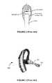
- FIG. 1is a drawing of a conventional headset 100 that has a wind screen 102 .
- the wind screen 102is placed over the headset microphone, which is typically located at the tip (i.e., the distal end) of the headset's microphone boom 104 , to shield the microphone from wind.
- a typical wind screen 102comprises a bulbous structure (sometimes referred to as a “wind sock”) made of foam or some other porous material, as illustrated in FIG. 2 .
- Wind noisecan be particularly problematic in headsets that employ short-length microphone booms, as are commonly employed in modern behind-the-ear Bluetooth headsets, such as the Bluetooth headset 300 shown in FIG. 3 .
- the headset 300Similar to the conventional binaural headband-based headset 100 in FIG. 1 , the headset 300 has a microphone boom 302 with a wind screen 304 covering a microphone at the distal end of the boom 302 . Because the boom 302 is short, however, when the headset 300 is being worn, the distance between the microphone and the headset wearer's mouth is greater than it is for the conventional headband-based headset 100 in FIG. 1 . This requires additional amplification to deliver the correct transmitted speech level to the telecommunications network, but the extra amplification also applies to the wind noise.
- the further a wind screen is separated from the microphonethe more effective the wind screen is at deflecting wind away from the headset's microphone.
- prior art approachestend to increase the diameter of the microphone boom, either along the boom's entire length, or towards the distal end of the boom, as is done in the behind-the-ear headset 300 in FIG. 3 .
- the increased diameter of the microphone boomprovides the ability to increase the separation between the wind screen and the microphone.
- the resulting microphoneis often larger and less discreet than desired, and, in some cases, can even be obtrusive and uncomfortable for the headset wearer.
- An exemplary miniaturized acoustic boom structureincludes a microphone boom housing having a wind screen and a microphone pod configured to hold a microphone.
- the microphone podhas an outer surface secured to an inner surface of the microphone boom housing, an interior having one or more surfaces configured to form an acoustic seal around at least a portion of the periphery of the microphone, and one or more pod port openings spaced away from one or more microphone ports of the microphone.
- the outer surface of the microphone podhas a wide cross-section near where the microphone pod is secured to the inner surface of the microphone boom housing and a relatively narrow cross-section at the one or more pod port openings.
- the microphone podincludes first and second pod port openings that provide sound wave access to opposing sides of a diaphragm of the microphone.
- the first and second pod port openingsare spaced away from first and second microphone ports of the microphone so that an acoustic path length between the first and second pod port openings is greater than an acoustic path length between the first and second microphone ports.
- FIG. 1is a drawing of a conventional headset equipped with a wind screen
- FIG. 2is a drawing showing a typical microphone wind screen and its physical relationship to an internal microphone and microphone boom;
- FIG. 3is a drawing of a typical behind-the-ear Bluetooth headset employing a short-length microphone boom;
- FIG. 4is a cross-sectional drawing of a miniaturized acoustic boom structure, according to an embodiment of the present invention.
- FIG. 5is a cross-sectional drawing of an alternative microphone boom pod that may be used in the miniaturized acoustic boom structure in FIG. 4 , according to an embodiment of the present invention.
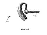
- FIG. 6is a headset equipped with the miniaturized acoustic boom structure in FIG. 4 , according to an embodiment of the present invention.
- the miniaturized acoustic boom structure 400comprises a microphone boom housing 402 and first and second microphone pods 404 and 406 secured to an inner wall of the microphone boom housing 402 .
- the microphone boom housing 402or a substantial portion thereof, comprises a perforated, porous or mesh-like material, which serves as a wind screen.
- the microphone boom housing 402is approximately 65 mm long and the first and second microphone pods 404 and 406 are separated from each other by about 40 mm.
- the first and second microphones 408 and 410are directional microphones, although other types of microphones (e.g., one or more omnidirectional microphones) may alternatively be used.
- the directional microphones 408 and 410are oriented within the microphone boom 402 , as indicated by the large directionality arrows pointing toward the distal end of the microphone boom housing 402 in FIG. 4 .
- Two microphonesare used in the exemplary embodiment shown in FIG. 4 , to account for the reduced ability to take advantage of the proximity effect when the acoustic boom structure 400 is designed to have a short-length boom. For longer length booms, which are more able to take advantage of the proximity effect, a microphone boom employing only a single microphone may alternatively be used.
- the first and second microphone pods 404 and 406each have a front pod port opening 414 a and a rear pod port opening 414 b .
- the front and rear pod port openings 414 a and 414 bprovide sound wave access to opposing sides of diaphragms of the first and second directional microphones 408 and 410 , via front and rear microphone ports 412 a and 412 b , respectively.
- the microphones 408 and 410are acoustically sealed around their periphery to the first and second microphone pods 404 and 406 respectively, to assure that air cavities on both sides of each of the microphones 408 and 410 are isobaric chambers.
- each of the microphone pods 404 and 406This allows the front pod port opening 414 a of each of the microphone pods 404 and 406 to be acoustically coupled to the front microphone port 412 a while being decoupled from the rear microphone port 412 b , and the rear pod port opening 414 b of each of the microphone pods 404 and 406 to be acoustically coupled to the rear microphone port 412 b while being decoupled from the front microphone port 412 a.
- the acoustic path length between the front and rear pod port openings 414 a and 414 b of each of the first and second microphone pods 404 and 406is greater than that between the front and rear microphone ports 412 a and 412 b .
- the spacing between the front and rear pod port opening 412 a and 412 b of each of the first and second microphone pods 404 and 406is designed to increase the time and amplitude differences between sound waves arriving at opposite sides of the microphone diaphragms, thereby increasing the microphones' sensitivity to sound pressure.
- the spacing between the front and rear pod port openings 412 a and 412 b of each of the first and second microphone pods 404 and 406is between about 6 and 9 mm.
- the outer surface of the first microphone pod 404has a wide cross-section near where the first microphone 408 is secured to the inner wall of the microphone boom housing 402 and a relatively narrow cross-section at the front and rear pod port openings 414 a and 414 b .
- the outer surface of the second microphone pod 406has a wide cross-section near where the second microphone 410 is secured to the inner wall of the microphone boom housing 402 and a relatively narrow cross-section at the front and rear pod port openings 414 a and 414 .
- each of the first and second microphone pods 404 and 408is ovate, i.e., is egg-shaped with an outer surface that tapers from a wide medial cross-section to truncated ends defining the front and rear pod port openings 414 a and 414 b . Tapering the outer surfaces of the microphone pods 404 and 406 minimizes the volume inside the microphone boom housing 402 needed to accommodate the microphone pods 404 and 406 .
- the remaining volume exterior to the microphone pods 404 and 406allows wind-induced acoustic noise to be attenuated by dispersion as the wind-induced acoustic noise propagates from the surface of the wind screen to the front and rear pod port openings 414 a and 414 b . While the first and second microphone pods 404 and 406 have been described as having egg-shaped outer surfaces, other microphone pod shapes may be alternatively be used, as will be readily appreciated and understood by those of ordinary skill in the art.
- the first and second microphone pods 404 and 406are designed to hold the first and second microphones 408 and 410 so that the front and rear microphone ports 412 a and 412 b of each of the microphones 406 and 408 directly face the front and rear pod port openings 414 a and 414 b .
- the largest diameter (or cross-sectional dimension, if the boom housing has a non-circular cross-section) required to accommodate the first and second microphones 408 and 410therefore, need only be approximately equal to the diameter of one of the microphones 408 and 410 or, more precisely, a microphone diameter plus two pod wall thicknesses.
- the microphone boom housing 402has a circular cross-section and 3-mm diameter disc microphones are used; so the cross-sectional diameter of the microphone boom housing 402 needs to be only slightly larger
- the diameter of the microphone boom housing 402may be further reduced by orienting each of the microphones 408 and 410 so that their largest dimension is oriented along the length of the microphone boom 402 .
- FIG. 5shows, for example, an alternative microphone pod 504 that is designed to hold its microphone 508 in this manner.
- the largest dimension of the microphonein this case, the microphone's diameter
- the front and rear microphone ports 412 a and 412 b of the microphone 508are oriented perpendicular to the front and rear pod port openings 414 a and 414 b.
- FIG. 5further illustrates how wires 510 and 512 of the microphone 508 may be advantageously fed through one of the pod port openings 414 a and 414 b , rather than having to route them along the outer surface of the microphone pod 504 .
- the samemay be done for wires of the microphones 408 and 410 held in the first and second microphone pods 404 and 406 in FIG. 4 , as will be readily appreciated and understood by those of ordinary skill in the art.
- Routing the wires through the pod port openingsavoids the problem of forming acoustic seals around the wires 510 and 512 , as must be addressed when the wires 510 and 512 are routed along the outer surfaces of the microphone pods.
- the microphone pods 404 and 406are made from an electrically insulating material. Accordingly, when configured in the microphone boom housing 400 , the microphone pods 404 and 406 increase the electrostatic discharge (ESD) path from the metal casings of the microphones 408 and 410 to the outside of the microphone boom housing 402 . The increased ESD path provides greater discharge protection for both the microphones 408 and 410 and the headset wearer. To maximize ESD protection, the microphone pods 404 and 406 can be made to be gas tight everywhere except for the front and rear pod port openings 414 a and 414 b.
- ESDelectrostatic discharge
- the miniaturized acoustic boom structure 400 in FIG. 4may be used in any type of headset in which wind noise reduction is desired. It is particularly advantageous to use it in short-boom headsets.
- FIG. 6illustrates, for example, how the miniaturized acoustic boom structure 400 in FIG. 4 is used in a behind-the-ear Bluetooth headset 600 .
- Use of the miniaturized boom structure 400results in a headset 600 that is smaller and less obtrusive to wear than prior art headsets equipped with noise reducing wind screens, yet which is still as, or more, effective at reducing wind noise.
Landscapes
- Physics & Mathematics (AREA)
- Engineering & Computer Science (AREA)
- Acoustics & Sound (AREA)
- Signal Processing (AREA)
- Details Of Audible-Bandwidth Transducers (AREA)
Abstract
Description
Claims (25)
Priority Applications (2)
| Application Number | Priority Date | Filing Date | Title |
|---|---|---|---|
| US12/114,583US8208673B2 (en) | 2008-05-02 | 2008-05-02 | Miniaturized acoustic boom structure for reducing microphone wind noise and ESD susceptibility |
| PCT/US2009/034894WO2009134519A1 (en) | 2008-05-02 | 2009-02-23 | Miniaturized acoustic boom structure for reducing microphone wind noise and electrostatic discharge susceptibility |
Applications Claiming Priority (1)
| Application Number | Priority Date | Filing Date | Title |
|---|---|---|---|
| US12/114,583US8208673B2 (en) | 2008-05-02 | 2008-05-02 | Miniaturized acoustic boom structure for reducing microphone wind noise and ESD susceptibility |
Publications (2)
| Publication Number | Publication Date |
|---|---|
| US20090274332A1 US20090274332A1 (en) | 2009-11-05 |
| US8208673B2true US8208673B2 (en) | 2012-06-26 |
Family
ID=40562866
Family Applications (1)
| Application Number | Title | Priority Date | Filing Date |
|---|---|---|---|
| US12/114,583Active2031-01-24US8208673B2 (en) | 2008-05-02 | 2008-05-02 | Miniaturized acoustic boom structure for reducing microphone wind noise and ESD susceptibility |
Country Status (2)
| Country | Link |
|---|---|
| US (1) | US8208673B2 (en) |
| WO (1) | WO2009134519A1 (en) |
Cited By (3)
| Publication number | Priority date | Publication date | Assignee | Title |
|---|---|---|---|---|
| US8976957B2 (en) | 2013-05-15 | 2015-03-10 | Google Technology Holdings LLC | Headset microphone boom assembly |
| US9877097B2 (en) | 2015-06-10 | 2018-01-23 | Motorola Solutions, Inc. | Slim-tunnel wind port for a communication device |
| US10701481B2 (en) | 2018-11-14 | 2020-06-30 | Townsend Labs Inc | Microphone sound isolation baffle and system |
Families Citing this family (9)
| Publication number | Priority date | Publication date | Assignee | Title |
|---|---|---|---|---|
| US20110103634A1 (en)* | 2009-11-02 | 2011-05-05 | Blueant Wireless Pty Limited | System and method for mechanically reducing unwanted wind noise in an electronics device |
| US20110105196A1 (en)* | 2009-11-02 | 2011-05-05 | Blueant Wireless Pty Limited | System and method for mechanically reducing unwanted wind noise in a telecommunications headset device |
| US20120076320A1 (en)* | 2010-09-28 | 2012-03-29 | Bose Corporation | Fine/Coarse Gain Adjustment |
| US8923522B2 (en)* | 2010-09-28 | 2014-12-30 | Bose Corporation | Noise level estimator |
| US20120076321A1 (en)* | 2010-09-28 | 2012-03-29 | Bose Corporation | Single Microphone for Noise Rejection and Noise Measurement |
| CN101984674B (en)* | 2010-10-19 | 2012-12-05 | 歌尔声学股份有限公司 | Earphone de-noising microphone rod device |
| US9118989B2 (en)* | 2012-09-05 | 2015-08-25 | Kaotica Corporation | Noise mitigating microphone attachment |
| US8737662B2 (en) | 2012-09-05 | 2014-05-27 | Kaotica Corporation | Noise mitigating microphone attachment |
| USD733690S1 (en) | 2013-10-30 | 2015-07-07 | Kaotica Corporation | Noise mitigating microphone attachment |
Citations (17)
| Publication number | Priority date | Publication date | Assignee | Title |
|---|---|---|---|---|
| US2520706A (en)* | 1948-01-30 | 1950-08-29 | Rca Corp | Windscreen for microphones |
| US4570746A (en)* | 1983-06-30 | 1986-02-18 | International Business Machines Corporation | Wind/breath screen for a microphone |
| US4720857A (en)* | 1985-12-06 | 1988-01-19 | Plantronics, Inc. | Miniaturized headset for two-way voice communication |
| US4875233A (en)* | 1987-10-16 | 1989-10-17 | Derhaag Robert L | Headset construction and method of making same |
| WO1996015646A1 (en) | 1994-11-14 | 1996-05-23 | Andrea Electronics Corporation | Noise cancellation headset for use with stand or worn on ear |
| US5615273A (en)* | 1992-09-29 | 1997-03-25 | Unex Corporation | Microphone assembly in a microphone boom of a headset |
| US20040156012A1 (en) | 2002-07-26 | 2004-08-12 | James Jannard | Electronic eyewear with hands-free operation |
| US20040258267A1 (en)* | 2001-11-07 | 2004-12-23 | Niels Erik Holm Christensen | Microphone unit |
| US6935458B2 (en)* | 2001-09-25 | 2005-08-30 | Thomas G. Owens | Microphone shroud and related method of use |
| US7062059B1 (en)* | 2004-06-25 | 2006-06-13 | Plantronics, Inc | Multi-function microphone boom with on-line indicator |
| US7190797B1 (en)* | 2002-06-18 | 2007-03-13 | Plantronics, Inc. | Headset with foldable noise canceling and omnidirectional dual-mode boom |
| US20070116315A1 (en) | 2005-11-15 | 2007-05-24 | Intricon Corporation | Earset microphone |
| US7349547B1 (en) | 2001-11-20 | 2008-03-25 | Plantronics, Inc. | Noise masking communications apparatus |
| US7391863B2 (en)* | 2004-06-23 | 2008-06-24 | Vocollect, Inc. | Method and system for an interchangeable headset module resistant to moisture infiltration |
| US7945063B2 (en)* | 2000-05-25 | 2011-05-17 | Qnx Software Systems Co. | Microphone shield system |
| US8090135B2 (en)* | 2007-10-18 | 2012-01-03 | Cheng Uei Precision Industry Co., Ltd. | Communication headset |
| US8111853B2 (en)* | 2008-07-10 | 2012-02-07 | Plantronics, Inc | Dual mode earphone with acoustic equalization |
- 2008
- 2008-05-02USUS12/114,583patent/US8208673B2/enactiveActive
- 2009
- 2009-02-23WOPCT/US2009/034894patent/WO2009134519A1/enactiveApplication Filing
Patent Citations (17)
| Publication number | Priority date | Publication date | Assignee | Title |
|---|---|---|---|---|
| US2520706A (en)* | 1948-01-30 | 1950-08-29 | Rca Corp | Windscreen for microphones |
| US4570746A (en)* | 1983-06-30 | 1986-02-18 | International Business Machines Corporation | Wind/breath screen for a microphone |
| US4720857A (en)* | 1985-12-06 | 1988-01-19 | Plantronics, Inc. | Miniaturized headset for two-way voice communication |
| US4875233A (en)* | 1987-10-16 | 1989-10-17 | Derhaag Robert L | Headset construction and method of making same |
| US5615273A (en)* | 1992-09-29 | 1997-03-25 | Unex Corporation | Microphone assembly in a microphone boom of a headset |
| WO1996015646A1 (en) | 1994-11-14 | 1996-05-23 | Andrea Electronics Corporation | Noise cancellation headset for use with stand or worn on ear |
| US7945063B2 (en)* | 2000-05-25 | 2011-05-17 | Qnx Software Systems Co. | Microphone shield system |
| US6935458B2 (en)* | 2001-09-25 | 2005-08-30 | Thomas G. Owens | Microphone shroud and related method of use |
| US20040258267A1 (en)* | 2001-11-07 | 2004-12-23 | Niels Erik Holm Christensen | Microphone unit |
| US7349547B1 (en) | 2001-11-20 | 2008-03-25 | Plantronics, Inc. | Noise masking communications apparatus |
| US7190797B1 (en)* | 2002-06-18 | 2007-03-13 | Plantronics, Inc. | Headset with foldable noise canceling and omnidirectional dual-mode boom |
| US20040156012A1 (en) | 2002-07-26 | 2004-08-12 | James Jannard | Electronic eyewear with hands-free operation |
| US7391863B2 (en)* | 2004-06-23 | 2008-06-24 | Vocollect, Inc. | Method and system for an interchangeable headset module resistant to moisture infiltration |
| US7062059B1 (en)* | 2004-06-25 | 2006-06-13 | Plantronics, Inc | Multi-function microphone boom with on-line indicator |
| US20070116315A1 (en) | 2005-11-15 | 2007-05-24 | Intricon Corporation | Earset microphone |
| US8090135B2 (en)* | 2007-10-18 | 2012-01-03 | Cheng Uei Precision Industry Co., Ltd. | Communication headset |
| US8111853B2 (en)* | 2008-07-10 | 2012-02-07 | Plantronics, Inc | Dual mode earphone with acoustic equalization |
Non-Patent Citations (2)
| Title |
|---|
| International Searching Authority: European Patent Office. International Search Report: PCT/US2009/034894. May 2009. Netherlands, Rijswijk. |
| International Searching Authority: European Patent Office. Written Opinion of the International Searching Authority: PCT/US2009/034894. May 2009. Germany, Munich. |
Cited By (3)
| Publication number | Priority date | Publication date | Assignee | Title |
|---|---|---|---|---|
| US8976957B2 (en) | 2013-05-15 | 2015-03-10 | Google Technology Holdings LLC | Headset microphone boom assembly |
| US9877097B2 (en) | 2015-06-10 | 2018-01-23 | Motorola Solutions, Inc. | Slim-tunnel wind port for a communication device |
| US10701481B2 (en) | 2018-11-14 | 2020-06-30 | Townsend Labs Inc | Microphone sound isolation baffle and system |
Also Published As
| Publication number | Publication date |
|---|---|
| WO2009134519A1 (en) | 2009-11-05 |
| US20090274332A1 (en) | 2009-11-05 |
Similar Documents
| Publication | Publication Date | Title |
|---|---|---|
| US8208673B2 (en) | Miniaturized acoustic boom structure for reducing microphone wind noise and ESD susceptibility | |
| US12348932B2 (en) | Hearing assistance using active noise reduction | |
| CN107533838B (en) | Voice sensing using multiple microphones | |
| US10178464B2 (en) | Earpiece | |
| US7860263B2 (en) | Hearing device and method for reducing feedback therein | |
| AU2004203048B2 (en) | Active Noise Suppression for a Hearing Aid Device Which Can Be Worn in the Ear or a Hearing Aid Device With Otoplasty Which Can Be Worn in the Ear | |
| US20140093095A1 (en) | Porous cover structures for mobile device audio | |
| WO2019024394A1 (en) | Uplink noise reducing earphone | |
| JP2014155145A (en) | Earphone microphone | |
| EP2830324B1 (en) | Headphone and headset | |
| US20220417646A1 (en) | Active Noise Reduction Earbud | |
| US7881464B1 (en) | Microphone with reduced noise | |
| JP2009218687A (en) | Noise cancel type headphone | |
| WO2009071896A1 (en) | Apparatus for accurate ambient noise sensing and reduction in the presence of wind | |
| JP4535395B2 (en) | Transmitter | |
| JP7383165B2 (en) | Wireless headset with improved wind noise resistance | |
| US20240187771A1 (en) | Acoustic transducer unit | |
| CN110998714B (en) | Noise canceling headphones | |
| US20210295815A1 (en) | Sound output device | |
| JP2015080183A (en) | Earphone with howling prevention structure | |
| EP3148218B1 (en) | Acoustical module with acoustical filter | |
| CN1281042C (en) | Transmitter-receiver of communicaton terminal | |
| JP4428576B2 (en) | Handset | |
| TW202316865A (en) | Noise cancellation enabled headphone |
Legal Events
| Date | Code | Title | Description |
|---|---|---|---|
| AS | Assignment | Owner name:PLANTRONICS, INC., CALIFORNIA Free format text:ASSIGNMENT OF ASSIGNORS INTEREST;ASSIGNORS:GRAHAM, JOHN STEVEN;ISVAN, OSMAN KEMAL;REEL/FRAME:020899/0171 Effective date:20080502 | |
| STCF | Information on status: patent grant | Free format text:PATENTED CASE | |
| FEPP | Fee payment procedure | Free format text:PAYOR NUMBER ASSIGNED (ORIGINAL EVENT CODE: ASPN); ENTITY STATUS OF PATENT OWNER: LARGE ENTITY | |
| FPAY | Fee payment | Year of fee payment:4 | |
| AS | Assignment | Owner name:WELLS FARGO BANK, NATIONAL ASSOCIATION, NORTH CAROLINA Free format text:SECURITY AGREEMENT;ASSIGNORS:PLANTRONICS, INC.;POLYCOM, INC.;REEL/FRAME:046491/0915 Effective date:20180702 Owner name:WELLS FARGO BANK, NATIONAL ASSOCIATION, NORTH CARO Free format text:SECURITY AGREEMENT;ASSIGNORS:PLANTRONICS, INC.;POLYCOM, INC.;REEL/FRAME:046491/0915 Effective date:20180702 | |
| MAFP | Maintenance fee payment | Free format text:PAYMENT OF MAINTENANCE FEE, 8TH YEAR, LARGE ENTITY (ORIGINAL EVENT CODE: M1552); ENTITY STATUS OF PATENT OWNER: LARGE ENTITY Year of fee payment:8 | |
| AS | Assignment | Owner name:POLYCOM, INC., CALIFORNIA Free format text:RELEASE OF PATENT SECURITY INTERESTS;ASSIGNOR:WELLS FARGO BANK, NATIONAL ASSOCIATION;REEL/FRAME:061356/0366 Effective date:20220829 Owner name:PLANTRONICS, INC., CALIFORNIA Free format text:RELEASE OF PATENT SECURITY INTERESTS;ASSIGNOR:WELLS FARGO BANK, NATIONAL ASSOCIATION;REEL/FRAME:061356/0366 Effective date:20220829 | |
| AS | Assignment | Owner name:HEWLETT-PACKARD DEVELOPMENT COMPANY, L.P., TEXAS Free format text:NUNC PRO TUNC ASSIGNMENT;ASSIGNOR:PLANTRONICS, INC.;REEL/FRAME:065549/0065 Effective date:20231009 | |
| MAFP | Maintenance fee payment | Free format text:PAYMENT OF MAINTENANCE FEE, 12TH YEAR, LARGE ENTITY (ORIGINAL EVENT CODE: M1553); ENTITY STATUS OF PATENT OWNER: LARGE ENTITY Year of fee payment:12 |