US8208198B2 - Catadioptric projection objective - Google Patents
Catadioptric projection objectiveDownload PDFInfo
- Publication number
- US8208198B2 US8208198B2US11/653,366US65336607AUS8208198B2US 8208198 B2US8208198 B2US 8208198B2US 65336607 AUS65336607 AUS 65336607AUS 8208198 B2US8208198 B2US 8208198B2
- Authority
- US
- United States
- Prior art keywords
- sio2v
- objective
- image
- objective part
- intermediate image
- Prior art date
- Legal status (The legal status is an assumption and is not a legal conclusion. Google has not performed a legal analysis and makes no representation as to the accuracy of the status listed.)
- Expired - Fee Related, expires
Links
Images


Classifications
- G—PHYSICS
- G02—OPTICS
- G02B—OPTICAL ELEMENTS, SYSTEMS OR APPARATUS
- G02B17/00—Systems with reflecting surfaces, with or without refracting elements
- G02B17/08—Catadioptric systems
- G02B17/0804—Catadioptric systems using two curved mirrors
- G02B17/0816—Catadioptric systems using two curved mirrors off-axis or unobscured systems in which not all of the mirrors share a common axis of rotational symmetry, e.g. at least one of the mirrors is warped, tilted or decentered with respect to the other elements
- G—PHYSICS
- G02—OPTICS
- G02B—OPTICAL ELEMENTS, SYSTEMS OR APPARATUS
- G02B13/00—Optical objectives specially designed for the purposes specified below
- G02B13/16—Optical objectives specially designed for the purposes specified below for use in conjunction with image converters or intensifiers, or for use with projectors, e.g. objectives for projection TV
- G—PHYSICS
- G02—OPTICS
- G02B—OPTICAL ELEMENTS, SYSTEMS OR APPARATUS
- G02B17/00—Systems with reflecting surfaces, with or without refracting elements
- G02B17/08—Catadioptric systems
- G—PHYSICS
- G02—OPTICS
- G02B—OPTICAL ELEMENTS, SYSTEMS OR APPARATUS
- G02B17/00—Systems with reflecting surfaces, with or without refracting elements
- G02B17/08—Catadioptric systems
- G02B17/0804—Catadioptric systems using two curved mirrors
- G—PHYSICS
- G02—OPTICS
- G02B—OPTICAL ELEMENTS, SYSTEMS OR APPARATUS
- G02B17/00—Systems with reflecting surfaces, with or without refracting elements
- G02B17/08—Catadioptric systems
- G02B17/0804—Catadioptric systems using two curved mirrors
- G02B17/0812—Catadioptric systems using two curved mirrors off-axis or unobscured systems in which all of the mirrors share a common axis of rotational symmetry
- G—PHYSICS
- G02—OPTICS
- G02B—OPTICAL ELEMENTS, SYSTEMS OR APPARATUS
- G02B17/00—Systems with reflecting surfaces, with or without refracting elements
- G02B17/08—Catadioptric systems
- G02B17/0892—Catadioptric systems specially adapted for the UV
- G—PHYSICS
- G02—OPTICS
- G02B—OPTICAL ELEMENTS, SYSTEMS OR APPARATUS
- G02B21/00—Microscopes
- G02B21/02—Objectives
- G—PHYSICS
- G02—OPTICS
- G02B—OPTICAL ELEMENTS, SYSTEMS OR APPARATUS
- G02B21/00—Microscopes
- G02B21/33—Immersion oils, or microscope systems or objectives for use with immersion fluids
- G—PHYSICS
- G03—PHOTOGRAPHY; CINEMATOGRAPHY; ANALOGOUS TECHNIQUES USING WAVES OTHER THAN OPTICAL WAVES; ELECTROGRAPHY; HOLOGRAPHY
- G03F—PHOTOMECHANICAL PRODUCTION OF TEXTURED OR PATTERNED SURFACES, e.g. FOR PRINTING, FOR PROCESSING OF SEMICONDUCTOR DEVICES; MATERIALS THEREFOR; ORIGINALS THEREFOR; APPARATUS SPECIALLY ADAPTED THEREFOR
- G03F7/00—Photomechanical, e.g. photolithographic, production of textured or patterned surfaces, e.g. printing surfaces; Materials therefor, e.g. comprising photoresists; Apparatus specially adapted therefor
- G03F7/70—Microphotolithographic exposure; Apparatus therefor
- G03F7/70216—Mask projection systems
- G03F7/70225—Optical aspects of catadioptric systems, i.e. comprising reflective and refractive elements
- G—PHYSICS
- G03—PHOTOGRAPHY; CINEMATOGRAPHY; ANALOGOUS TECHNIQUES USING WAVES OTHER THAN OPTICAL WAVES; ELECTROGRAPHY; HOLOGRAPHY
- G03F—PHOTOMECHANICAL PRODUCTION OF TEXTURED OR PATTERNED SURFACES, e.g. FOR PRINTING, FOR PROCESSING OF SEMICONDUCTOR DEVICES; MATERIALS THEREFOR; ORIGINALS THEREFOR; APPARATUS SPECIALLY ADAPTED THEREFOR
- G03F7/00—Photomechanical, e.g. photolithographic, production of textured or patterned surfaces, e.g. printing surfaces; Materials therefor, e.g. comprising photoresists; Apparatus specially adapted therefor
- G03F7/70—Microphotolithographic exposure; Apparatus therefor
- G03F7/70216—Mask projection systems
- G03F7/70275—Multiple projection paths, e.g. array of projection systems, microlens projection systems or tandem projection systems
- G—PHYSICS
- G03—PHOTOGRAPHY; CINEMATOGRAPHY; ANALOGOUS TECHNIQUES USING WAVES OTHER THAN OPTICAL WAVES; ELECTROGRAPHY; HOLOGRAPHY
- G03F—PHOTOMECHANICAL PRODUCTION OF TEXTURED OR PATTERNED SURFACES, e.g. FOR PRINTING, FOR PROCESSING OF SEMICONDUCTOR DEVICES; MATERIALS THEREFOR; ORIGINALS THEREFOR; APPARATUS SPECIALLY ADAPTED THEREFOR
- G03F7/00—Photomechanical, e.g. photolithographic, production of textured or patterned surfaces, e.g. printing surfaces; Materials therefor, e.g. comprising photoresists; Apparatus specially adapted therefor
- G03F7/70—Microphotolithographic exposure; Apparatus therefor
- G03F7/70216—Mask projection systems
- G03F7/70341—Details of immersion lithography aspects, e.g. exposure media or control of immersion liquid supply
- G—PHYSICS
- G03—PHOTOGRAPHY; CINEMATOGRAPHY; ANALOGOUS TECHNIQUES USING WAVES OTHER THAN OPTICAL WAVES; ELECTROGRAPHY; HOLOGRAPHY
- G03F—PHOTOMECHANICAL PRODUCTION OF TEXTURED OR PATTERNED SURFACES, e.g. FOR PRINTING, FOR PROCESSING OF SEMICONDUCTOR DEVICES; MATERIALS THEREFOR; ORIGINALS THEREFOR; APPARATUS SPECIALLY ADAPTED THEREFOR
- G03F7/00—Photomechanical, e.g. photolithographic, production of textured or patterned surfaces, e.g. printing surfaces; Materials therefor, e.g. comprising photoresists; Apparatus specially adapted therefor
- G03F7/70—Microphotolithographic exposure; Apparatus therefor
- G03F7/708—Construction of apparatus, e.g. environment aspects, hygiene aspects or materials
- G03F7/7095—Materials, e.g. materials for housing, stage or other support having particular properties, e.g. weight, strength, conductivity, thermal expansion coefficient
- G03F7/70958—Optical materials or coatings, e.g. with particular transmittance, reflectance or anti-reflection properties
- G03F7/70966—Birefringence
- G—PHYSICS
- G02—OPTICS
- G02B—OPTICAL ELEMENTS, SYSTEMS OR APPARATUS
- G02B13/00—Optical objectives specially designed for the purposes specified below
- G02B13/22—Telecentric objectives or lens systems
Definitions
- the inventionrelates to a catadioptric projection objective for imaging a pattern arranged in an object surface onto an image surface.
- Projection objectives of that typeare employed on projection exposure systems, in particular wafer scanners or wafer steppers, used for fabricating semiconductor devices and other types of microdevices and serve to project patterns on photomasks or reticles, hereinafter referred to generically as “masks” or “reticles,” onto an object having a photosensitive coating with ultrahigh resolution on a reduced scale.
- NAnumerical aperture
- a flat (planar) imageis essential to expose planar substrates, such as semiconductor wafers.
- planar substratessuch as semiconductor wafers.
- the image surface of an optical systemis curved, and the degree of curvature is determined by the Petzval sum.
- the correction of the Petzval sumis becoming more important in view of the increasing demands to project large object fields on planar surfaces with increased resolution.
- catadioptric systemswhich combine both refracting elements, such as lenses, and reflecting elements, such as mirror, preferably including at least one concave mirror. While the contributions of positive-powered and negative-powered lenses in an optical system to overall power, surface curvature and chromatic aberrations are opposite to each other, a concave mirror has positive power like a positive-powered lens, but the opposite effect on surface curvature without contributing to chromatic aberrations.
- Catadioptric projection objectives having at least two concave mirrorshave been proposed to provide systems with good color correction and moderate lens mass requirements.
- the U.S. Pat. No. 6,600,608 B1discloses a catadioptric projection objective having a first, purely refractive objective part for imaging a pattern arranged in the object plane of the projection objective into a first intermediate image, a second objective part for imaging the first intermediate image into a second intermediate image and a third objective part for imaging the second intermediate image directly, that is without a further intermediate image, onto the image plane.
- the second objective partis a catadioptric objective part having a first concave mirror with a central bore and a second concave mirror with a central bore, the concave mirrors having the mirror faces facing each other and defining an intermirror space or catadioptric cavity in between.
- the first intermediate imageis formed within the central bore of the concave mirror next to the object plane, whereas the second intermediate image is formed within the central bore of the concave mirror next to the object plane.
- the objectivehas axial symmetry and provides good color correction axially and laterally. However, since the reflecting surfaces of the concave mirrors are interrupted at the bores, the pupil of the system is obscured.
- the Patent EP 1 069 448 B1discloses another catadioptric projection objective having two concave mirrors facing each other.
- the concave mirrorsare part of a first catadioptric objective part imaging the object onto an intermediate image positioned adjacent to a concave mirror. This is the only intermediate image, which is imaged to the image plane by a second, purely refractive objective part.
- the object as well as the image of the catadioptric imaging systemare positioned outside the intermirror space defined by the mirrors facing each other.
- European patent application EP 1 336 887discloses catadioptric projection objectives having one common straight optical axis and, in that sequence, a first catadioptric objective part for creating a first intermediate image, a second catadioptric objective part for creating a second intermediate image from the first intermediate image, and a refractive third objective part forming the image from the second intermediate image.
- Each catadioptric systemhas two concave mirrors facing each other. The intermediate images lie outside the intermirror spaces defined by the concave mirrors. Concave mirrors are positioned optically near to pupil surfaces closer to pupil surfaces than to the intermediate images of the projection objectives.
- a design example of a catadioptric projection lensis shown, which is a combination of a conventional dioptric DUV system and a 6-mirror EUV catoptric system inserted between lens groups of the DUV system.
- a first intermediate imageis formed behind the third mirror of the catoptric (purely reflective) group upstream of a convex mirror.
- the second intermediate imageis formed by a purely reflective (catoptric) second objective part.
- the third objective partis purely refractive featuring negative refractive power at a waist of minimum beam diameter within the third objective part for Petzval sum correction.
- Japanese patent application JP 2003114387 A and international patent application WO 01/55767 Adisclose catadioptric projection objectives having one common straight optical axis, a first catadioptric objective part for forming an intermediate image and a second catadioptric objective part for imaging the intermediate image onto the image plane of this system. Concave and convex mirrors are used in combination.
- a front refractive groupforms a first intermediate image near the first mirror and a second intermediate image is formed outside of the space formed by the two facing mirrors.
- a narrow field being larger in a horizontal direction than in a vertical directionis arranged offset to the optical axis.
- the object side refractive grouphas a collimated input and the image side refractive group has a collimated output and entrance and exit pupils far from telecentric are formed.
- the pupil shapeis semi-circular unlike pupil surfaces in lithographic projection lenses, which have to be circular and centered on the optical axis.
- the PCT application WO 01/04682 A1discloses catadioptric UV imaging systems for wafer inspection having one concave mirror designed as Mangin mirror.
- Catadioptric projection objectivesconsisting of a catadioptric imaging subsystem having one single concave mirror and arranged between an entry side and an exit side refractive imaging subsystem (so-calles R-C-R systems) are disclosed, for example, in U.S. application with Ser. No. 60/571,533 filed on May 17, 2004 by the applicant.
- Other examples of R-C-R-systemsare shown in US 2003/0011755, WO 03/036361 or US 2003/0197946.
- the projection objectivescomprise: a first objective part for imaging the pattern provided in the object plane into a first intermediate image, a second objective part for imaging the first intermediate imaging into a second intermediate image, and a third objective part for imaging the second intermediate imaging directly onto the image plane.
- the second objective partincludes a first concave mirror having a first continuous mirror surface and a second concave mirror having a second continuous mirror surface, the concave mirror faces facing each other and defining an intermirror space. All concave mirrors are positioned optically remote from pupil surfaces.
- the systemhas potential for very high numerical apertures at moderate lens mass consumption.
- VUVvacuum ultraviolet
- a catadioptric projection objective for imaging a pattern provided in an object surface of the projection objective onto an image surface of the projection objectivecomprising:
- a first, refractive objective partfor imaging the pattern provided in the object plane into a first intermediate image
- a second objective partincluding at least one concave mirror for imaging the first intermediate imaging into a second intermediate image
- the first compaction parameter COMP1should be as small as possible if a compact design is desired.
- projection objectives according to the inventionhave at least three objective parts for imaging an entry side field plane into an optically conjugate exit side field plane, where the imaging objective parts are concatenated at intermediate images.
- low values for the second compactness parametercan be obtained.
- COMP2 ⁇ 260 and/or COMP2 ⁇ 240is obtained.
- Embodiments with COMP2 ⁇ 220are possible.
- low values for the third compactness parameter COMP3are possible.
- COMP3 ⁇ 80, and lower values of COMP3 ⁇ 70are also possible.
- a first concave mirror having a first continuous mirror surface and at least one second concave mirror having a second continuous mirror surfaceare arranged in the second objective part; pupil surfaces are formed between the object plane and the first intermediate image, between the first and the second intermediate image and between the second intermediate image and the image plane; and all concave mirrors are arranged optically remote from a pupil surface.
- a circular pupil centered around the optical axisis be provided in a centered optical system.
- Two or more concave mirrors in the system parts contributing to forming the second intermediate imageare provided, where the used area of the concave mirrors deviates significantly from an axial symmetric illumination.
- exactly two concave mirrorsare provided and are sufficient for obtaining excellent imaging quality and very high numerical aperture.
- Systems having one common unfolded (straight) optical axiscan be provided which facilitate manufacturing, adjustment and integration into photolithographic exposure systems. No planar folding mirrors are necessary. However, one or more planar folding mirrors could be utilized to obtain more compact designs.
- the marginal ray height h Mis the height of a marginal ray running from an inner field point (closest to the optical axis) to the edge of an aperture stop
- the chief ray height h Cis the height of a chief ray running from an outermost field point (farthest away from the optical axis) parallel to or at small angle with respect to the optical axis and intersecting the optical axis at a pupil surface position where an aperture stop may be positioned.
- a position “optically remote” from a pupil surfaceis a position where the cross sectional shape of the light beam deviates significantly from the circular shape found in a pupil surface or in an immediate vicinity thereto.
- the term “light beam” as used heredescribes the bundle of all rays running from the object surface to the image surface.
- Mirror positions optically remote from a pupil surfacemay be defined as positions where the beam diameters of the light beam in mutually perpendicular directions orthogonal to the propagation direction of the light beam deviate by more than 50% or 100% from each other.
- illuminated areas on the concave mirrorsmay have a shape having a form strongly deviating from a circle and similar to a high aspect ratio rectangle corresponding to a preferred field shape in lithographic projection objectives for wafer scanners. Therefore, small concave mirrors having a compact rectangular or near rectangular shape significantly smaller in one direction than in the other may be used.
- a high aperture light beamcan therefore be guided through the system without vignetting at mirror edges.
- object partdesignates an imaging subsystem of the projection objective capable of imaging an object in an object surface of that subsystem into an image surface of the subsystem optically conjugated to the object surface of the subsystem.
- the object imaged by a subsystemmay be the object in the object surface of the projection objective, or an intermediate image.
- a position upstream of the second intermediate imageis a position optically between the object plane and the second intermediate image.
- intermediate imagegenerally refers to a “paraxial intermediate image” formed by a perfect optical system and located in a surface optically conjugated to the object surface. Therefore, wherever reference is made to a location or position of an intermediate image, the axial location of this surface optically conjugated to the object surface is meant.
- a catadioptric projection objective for imaging a pattern provided in an object surface of the projection objective onto an image surface of the projection objectivecomprises:
- a first, refractive objective partfor imaging the pattern provided in the object surface into a first intermediate image
- a first concave mirror having a first continuous mirror surface and at least one second concave mirror having a second continuous mirror surfaceare arranged upstream of the second intermediate image; pupil surfaces are formed between the object plane and the first intermediate image, between the first and the second intermediate image and between the second intermediate image and the image plane; all concave mirrors are arranged optically remote from a pupil surface;
- the first objective parthas a first number N1 AS of aspheric lenses;
- the first objective parthas no more than 4 aspheric lenses, i.e. N1 AS ⁇ 4.
- the first objective partcan be built in many cases with a small number of lenses, thereby optimizing lens material consumption and a compact size of the first objective part particularly in axial direction.
- the first objective partincludes no more than 5 lenses such that the number N1 L of lenses in the first objective part fulfills the condition N1 L ⁇ 5.
- the first objective parthas positive lenses only, whereby formation of the first intermediate image can be obtained with small maximum lens diameters in the first objective part.
- at least one negative lensmay be useful, particularly for improving correction within the first objective part. Exactly one negative lens is often preferred for that purpose.
- the negative lensmay have a concave lens surface on the image side and may be placed between the pupil surface of the first objective part and the first intermediate image.
- the projection objectiveincludes at least one “double asphere” comprising a first aspheric surface and a second aspheric surface immediately adjacent to the first aspheric surface, thereby allowing a transmitted beam to pass two subsequent aspheric surfaces without passing an intermediate spheric or planar surface. Double aspheres have proven to be a very powerful correction means in some embodiments.
- a double aspheremay take the structure of a biaspherical lens having an aspheric entrance surface and an aspheric exit surface.
- the double asphereis formed by facing adjacent aspheric surfaces of two subsequent lenses.
- an “air space”bounded by aspheric surfaces on both the entry and exit side can be obtained.
- the “air space”can be filled with air of another gas having refractive index n ⁇ 1.
- aspheric surfaces of a double asphereare distributed on facing lens surfaces of subsequent lenses, the aspheric surfaces can be positioned very close together if desired.
- An optical distance, measured along the optical axis, between the first and second aspheric surface of the double aspheremay therefore be smaller than the thickness (measured along the optical axis) of the thinner one of consecutive lenses forming the double asphere.
- a complex radial distribution of refractive powercan thereby be obtained at a defined position in an axially narrow region along the optical axis.
- the third objective partincludes at least one double asphere.
- that double asphereis positioned optically between the second intermediate image and the pupil surface of the third objective part, thereby preferably influencing the ray angles in a region of generally diverging beams.
- a second double aspheremay be provided in that objective part.
- the first objective partmay include at least one double asphere.
- a double asphereis provided within the first objective part, it has been found beneficial when the double asphere in the first objective part is positioned optically close to or at a pupil surface of the first objective part.
- the first objective partincludes at least one lens having a lens surface where incidence angles of rays transiting that lens surface include incidence angles larger than 60°.
- that surfacemay be optically close to the pupil surface
- the angle of incidence (incidence angle) in this caseis defined as the angle enclosed by a ray and the surface normal of the lens surface at the point of impingement of that ray on the lens surface.
- High incidence angle surfaces of that kindmay be employed to reduce the number of aspheres.
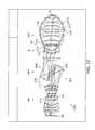
- FIG. 1is a longitudinally sectioned view of a first embodiment of a projection objective according to the invention
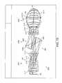
- FIG. 2is a longitudinally sectioned view of a second embodiment of a projection objective according to the invention.
- FIG. 3is a longitudinally sectioned view of a third embodiment of a projection objective according to the invention.
- FIG. 4is a longitudinally sectioned view of a fourth embodiment of a projection objective according to the invention.
- FIG. 5is a longitudinally sectioned view of a fifth embodiment of a projection objective according to the invention.
- FIG. 6is a longitudinally sectioned view of a sixth embodiment of a projection objective according to the invention.
- FIG. 7is a longitudinally sectioned view of a seventh embodiment of a projection objective according to the invention.
- FIG. 8is a longitudinally sectioned view of a eighth embodiment of a projection objective according to the invention.
- FIG. 9is a longitudinally sectioned view of a ninth embodiment of a projection objective according to the invention.
- FIG. 10is a longitudinally sectioned view of a tenth embodiment of a projection objective according to the invention.
- FIG. 11is a longitudinally sectioned view of a eleventh embodiment of a projection objective according to the invention.
- FIG. 12is a longitudinally sectioned view of a twelfth embodiment of a projection objective according to the invention.
- FIG. 13is a longitudinally sectioned view of a thirteenth embodiment of a projection objective according to the invention.
- FIG. 14is a longitudinally sectioned view of a fourteenth embodiment of a projection objective according to the invention.
- FIG. 15is a longitudinally sectioned view of a fifteenth embodiment of a projection objective according to the invention.
- FIG. 16is a longitudinally sectioned view of a sixteenth embodiment of a projection objective according to the invention.
- optical axisshall refer to a straight line or sequence of straight-line segments passing through the centers of curvature of the optical elements involved.
- the optical axisis folded by folding mirrors (deflecting mirrors) or other reflective surfaces.
- the object involvedis either a mask (reticle) bearing the pattern of an integrated circuit or some other pattern, for example, a grating pattern.
- the image of the objectis projected onto a wafer serving as a substrate that is coated with a layer of photoresist, although other types of substrate, such as components of liquid-crystal displays or substrates for optical gratings, are also feasible.
- an identification L 3 - 2denotes the second lens in the third objective part (when viewed in the light propagation direction).
- FIG. 1shows a first embodiment of a catadioptric projection lens 100 according to the invention designed for ca. 193 nm UV working wavelength. It is designed to project an image of a pattern on a reticle arranged in the planar object surface OS (object plane) into the planar image surface IS (image plane) on a reduced scale, for example, 4:1, while creating exactly two real intermediate images IMI 1 , IMI 2 .
- a first refractive objective part OP 1is designed for imaging the pattern in the object surface into the first intermediate image IMI 1 at an enlarged scale.
- a second, catoptric (purely reflective) objective part OP 2images the first intermediate image IMI 1 into the second intermediate image IMI 2 at a magnification close to 1:1.
- a third, refractive objective part OP 3images the second intermediate image IMI 2 onto the image surface IS with a strong reduction ratio.
- the second objective part OP 2comprises a first concave mirror CM 1 having the concave mirror surface facing the object side, and a second concave mirror CM 2 having the concave mirror surface facing the image side.
- the mirror surfacesare both continuous or unbroken, i.e. they do not have a hole or bore.
- the mirror surfaces facing each otherdefine a catadioptric cavity, which is also denoted intermirror space, enclosed by the curved surfaces defined by the concave mirrors.
- the intermediate images IMI 1 , IMI 2are both situated inside the catadioptric cavity well apart from the mirror surfaces.
- Each mirror surface of a concave mirrordefines a “curvature surface” or “surface of curvature” which is a mathematical surface extending beyond the edges of the physical mirror surface and containing the mirror surface.
- the first and second concave mirrorsare parts of rotationally symmetric curvature surfaces having a common axis of rotational symmetry.
- the objective 100is rotational symmetric and has one straight optical axis AX common to all refractive and reflective optical components. There are no folding mirrors.
- the concave mirrorshave small diameters allowing to bring them close together and rather close to the intermediate images lying in between.
- the concave mirrorsare both constructed and illuminated as off-axis sections of axial symmetric surfaces. The light beam passes by the edges of the concave mirrors facing the optical axis without vignetting.
- the refractive first objective part OP 1has spherical lenses only. Both concave mirrors CM 1 , CM 2 are aspherical mirrors.
- the third objective part OP 3has one aspheric surface (entrance surface of lens L 3 - 9 ) near the position of the pupil surface P 3 of that objective part (where the chief ray CR of the imaging intersects the optical axis AX) and a second aspheric surface on the exit side of the penultimate lens L 3 - 12 immediately upstream of the last, image side plano-convex lens L 3 - 13 .
- the last lenswhich will be in contact with an immersion fluid during operation of the projection objective, is also denoted “immersion lens” in this specification.
- FIG. 2shows a second embodiment of a projection objective 200 having an all-spheric first objective part OP 1 and only one aspheric lens L 3 - 4 in third objective part OP 3 .
- An aperture stop ASis placed in the third objective part in the region of the pupil surface PS 3 thereof.
- the first objective part OP 1which, in this case, consists of only four lenses, all lenses being spherical positive lenses. Thereby, a very simple and compact construction of the first objective part is obtained.
- a high index immersion fluide.g. pure water
- the specification for this designis summarized in Table 2.
- the leftmost columnlists the number of the refractive, reflective, or otherwise designated surface
- the second columnlists the radius, r, of that surface [mm]
- the third columnlists the distance, d [mm] between that surface and the next surface, a parameter that is referred to as the “thickness” of the optical element
- the fourth columnlists the material employed for fabricating that optical element
- the fifth columnlists the refractive index of the material employed for its fabrication.
- the sixth columnlists the optically utilizable, clear, semi diameter [mm] of the optical component.
- three surfacesare aspherical surfaces.
- the first lens L 3 - 1 of the third objective parthas a relatively large geometrical distance to the vertex of the geometrically nearest mirror (first concave mirror CM 1 ), where that axial mirror-lens-distance MLD is 90 mm. This is about 7.5% of the axial distance between object surface OS and image surface IS, this object-image distance also being denoted as “track length”.
- a large geometrical distance MLD between the image side first concave mirror CM 1 and the first lens of the third objective partcontributes to small lens diameters in the third objective part.
- the last lens L 3 - 9 on the image side(immersion lens) has a short radius (50 mm) of the spherical entrance surface, whereby small incidence angles are obtained at that surface.
- the designcan be optimized with regard to residual aberrations, where higher order Petzval curvature and higher order sagitta oblique spherical aberration appears to dominate. Adding one lens to the first objective part and/or providing one or more further aspheric surfaces can contribute to reduce the residual aberrations.
- An example of a further development of the design of FIG. 2is shown in FIG. 3 , where an additional negative lens L 1 - 4 designed as a meniscus lens having an image side concave surface is added in the first objective part between the pupil surface P 1 thereof and the first intermediate image. This modification allows to correct the mentioned residual aberrations.
- This exampleexemplifies, amongst others, that the basic design allows high flexibility for correcting imaging errors within overall simple construction with small number of lenses and a small number of aspherical lenses.
- FIG. 4A fourth embodiment of a projection objective 400 is shown in FIG. 4 , the specification thereof is given in tables 4 and 4A. Similar to the embodiments of FIGS. 2 and 3 , there is only one aspheric lens, namely positive meniscus lens L 3 - 4 having an aspheric exit surface, in that system, placed in the third objective part OP 3 in the region of largest beam diameter upstream of the aperture stop AS optically close to the pupil surface P 3 of that objective part.
- the first objective part OP 1is all-spherical, having only one negative lens L 1 - 4 in a sequence P-P-P-N-P, where “P” denotes a positive lens and “N” denotes a negative lens. From a construction point of view, a large axial distance between the vertex of the image side concave mirror CM 1 and the first lens L 3 - 1 of the third objective part OP 3 is apparent, this distance MLD being more than 10% of the track length.
- FIG. 5shows a variant of the systems of FIGS. 3 and 4 , where slight modifications predominantly in the first objective part OP 1 were applied to a improve correction.
- the resulting design of FIG. 5has two field points that are corrected for both astigmatism and Petzval curvature, and the field zone with no astigmatism is in focus.
- distortion, astigmatism, Petzval curvature and telecentricity variation over the fieldcan all be corrected to very high orders with a similar construction of the first objective part OP 1 (serving as a relay system to form the first intermediate image IMI 1 ) and only a few spherical lenses in addition to the aspheric mirrors.
- two aspheric concave mirrors CM 1 , CM 2are important for obtaining good correction with a small number of aspheric lenses.
- Two aspheric mirrorsgenerally allow to make a design that is corrected for two chief ray aberrations, like distortion and telecentricity variation, to very high orders. It appears that those two aberrations can be exactly corrected by the two aspheric mirrors if the aspheric deformations of that mirrors are set correctly. It is one remarkable aspect, that, in addition, the astigmatism and Petzval curvature can also be corrected to a high degree with an all-spherical first objective part OP 1 .
- the concave mirrorsmay preferably be quite unequal in radius, compared to other embodiments where the concave mirrors CM 1 , CM 2 are identical or almost identical. Further, it appears that quite a lot of coma at the intermediate images IMI 1 and/or IMI 2 facilitates correction with a small number of aspheric lenses. Also, the remarkably large air space (mirror-lens-distance MLD) between the vertex of the image side concave mirror CM 1 and the first lens of the third objective part appears to contribute to that beneficial properties.
- the object side and the image side and/or the projection objectivei.e. the first objective part OP 1 and the third objective part OP 3
- the third objective partfocusing lens group
- a first objective part being relatively simple in constructioncan be designed to compensate for field aberration, wherein that compensation might be obtained without aspheric lenses or with only a small number of aspheric lens, e.g. only one aspheric lens.
- FIGS. 6 and 7show closely related embodiments 600 , 700 , where the number of aspheric lenses in the refractive first and third objective part is increased when compared to the previous embodiments.
- the specification of objective 700is given in tables 7 and 7A.
- An improvement with respect to aperture aberrationsis obtained.
- the design of FIG. 6 having two aspheric lenses L 1 - 2 and L 1 - 5 in the first objective part OP 1has an wavefront aberration of 5 milliwaves over the field.
- One double asphere DAis provided in the third objective part OP 3 optically between a second intermediate image IMI 2 and the pupil surface P 3 of that objective part in a region of significantly increasing beam diameter.
- the double asphereis formed by the aspheric exit surface of positive lens L 3 - 6 and the subsequent aspheric entry surface of the following positive meniscus lens L 3 - 7 immediately adjacent thereto.
- the axial separation of the two aspheric surfacesis smaller than the thickness of the thinner lens L 3 - 7 adjacent to the double asphere such that the aspheres are in close proximity.
- a complex radial distribution of refractive poweris thereby obtained in a specific region of the beam, thereby contributing strongly to image correction.
- FIGS. 8 and 9show embodiments 800 , 900 very similar in design.
- the specification of projection objective 900is given in tables 9, 9A.
- These aspheric lensesinclude a biconcave negative meniscus L 3 - 2 , a double asphere DA formed by a lens pair L 3 - 5 , L 3 - 6 with facing aspheric surfaces, a biconvex positive lens L 3 - 9 close to the aperture stop AS, and a positive lens L 3 - 10 between the aperture stop and the image surface IS.
- the front pupil in the relay section formed by first objective part OP 1is pretty well corrected.
- a focus region with little or no coma aberrations (low-coma intermediate image) for both intermediate images IMI 1 and IMI 2is apparent.
- the low-coma intermediate image IMI 2is refocused onto the image surface with refractive objective part OP 3 having a thick positive lens L 3 - 1 on the entry side and a significant waist W (i.e. a region of beam diameter constriction) between the first lens L 3 - 1 and the region of largest beam diameter shortly upstream of the aperture stop AS.
- Double asphere DAis placed in the divergent beam between the waist and the aperture stop AS.
- the projection objective 1000 in FIG. 10may in some respects be considered as a variant of the embodiments shown in FIGS. 8 and 9 .
- a specification thereofis given in tables 10, 10A.
- an all-spherical doublettconsisting of an image-side biconvex positive lens L 1 - 6 and a negative meniscus lens L 1 - 7 having an object side concave surface immediately downstream of the positive lens is positioned near the pupil surface P 1 .
- the spherical surfaces of the doublett lenses L 1 - 6 , L 1 - 7are easier to manufacture, manufacturability can be improved in some cases by replacing an aspheric lens by one or more spherical lens surfaces where high incidence angles occur.
- a spherical doublettmay therefore be able to replace an aspheric surface—even a very high order aspheric.
- the correction status of variants of embodiment 1000ranges between 4, 5 and 6 milliwaves over the field. This indicates that this correction can be obtained with an all-spherical first objective part OP 1 and that the complete design does not need many aspheric lenses (only 5 lens aspherics here) to obtain a good performance.
- the specification of the catadioptric projection objective 1100is given in tables 11, 11A.
- the embodimentis a good example to show that “double aspheres” having two pretty strong aspheric lens surfaces very close to each other may be a very powerful design component.
- a double asphere DA formed by lenses L 3 - 4 and L 3 - 5is found in the region of increasing beam diameter within the third objective part OP 3 , similar to the embodiments shown in FIGS. 8 , 9 , and 10 , for example.
- a second double asphere DA formed by the facing surfaces of lenses L 1 - 5 and L 1 - 6is present optically near the front pupil, i.e. the pupil surface P 1 of the first objective part OP 1 .
- the largest lens diameter(found shortly upstream of the aperture stop AS within the third objective part OP 3 ) is 270 mm.
- the field radiusis 66 mm.
- the correctionis about 4 to 6 milliwaves over the field.
- the designassumes exactly telecentric input. It is evident that from the ray configuration at the intermediate images that there is a large amount of coma at the intermediate images.
- the specificationis given in tables 13, 13A.
- the largest lens diameteris only 250 mm (instead of 270 mm in embodiment 1200 ).
- the wavefront erroris about 4 milliwaves over the field only.
- the designis characterized by the absence of a real stop so that a telecentric input is required. Again a large amount of coma is found at the intermediate images.
- Four out of eleven aspheric lensesare found in the first objective part OP 1 , the remainder of seven aspheric lenses is distributed in the third objective part OP 3 .
- manufacturability of the aspheric lensesis improved by observing the requirement that all of the aspheric lens surfaces have less than 1.0 mm deformation from a spheric surface and have local aspheric radii being greater than 150 mm for each aspheric surface.
- One double asphere DA formed by lenses L 1 - 6 and L 1 - 7 positioned at the pupil surface P 1 within the first objective part OP 1is designed to have fairly high incidence angles which appears to have a similar effect as short local aspheric radii (which are more difficult to manufacture).
- the third objective part OP 3There are two double aspheres DA in the third objective part OP 3 , namely one double asphere formed by facing surfaces of negative lenses L 3 - 1 , L 3 - 2 in the region of minimum lens diameter within the third objective part, and a subsequent double aspheric formed by facing surfaces of lenses L 3 - 3 and L 3 - 4 in the region of largest beam diameter increase between the second intermediate image IMI 2 and the aperture stop AS, which is positioned between the region of largest beam diameter and the image surface IS.
- large amount of comais present in the intermediate images IMI 1 , IMI 2 .
- the catadioptric immersion objective 1500 in FIG. 15(specification in tables 15 and 15A) is a variant of the embodiment shown in FIG. 14 , where sizes and types of lenses present in the objective 1500 are essentially the same.
- a differencelies in the fact that an additional biconvex positive lens L 3 - 1 is introduced immediately after the second intermediate image IMI 2 , thereby providing positive refractive power on the entry side of third objective part OP 3 .
- the basic designhas potential for even higher image side numerical apertures with NA>1.3.
- there are ten lenses in the first objective partincluding 4 aspheric lenses
- twelve lenses in the third objective partincluding 7 aspheric lenses.
- lens thickness, surface radii and lens positionsdiffer slightly.
- only three positive lensesare placed between the aperture stop and the image surface.
- the second objective part OP 2may be beneficial to place the second objective part OP 2 geometrically closer to the image surface the higher the desired numerical aperture is.
- the second objective part OP 2preferably consisting of two aspheric concave mirrors CM 1 , CM 2 only, is also denoted “mirror group” in the following.
- a first optical axis length OAL 1is defined between the object surface OS and the vertex of the concave mirror CM 2 geometrically closest to the object surface
- a third optical axis length OAL 3is defined between the vertex of the concave mirror (CM 1 ) geometrically closest to the image surface and the image surface (see FIG. 16 ).
- OAL 1 , OAL 3 and MGare summarized for all embodiments described here.
- a mirror group position parameter MG>0.7appears to be desirable in order to obtain high image side numerical apertures.
- Each projection objective described herehas a high NA image side end where projection radiation exits the projection objective at an exit surface ES, which is preferably planar in order to allow a uniform distance between the exit surface and a planar substrate surface arranged at the image surface IS.
- the lens closest to the image surface and forming the exit surface ESis denoted “last lens” LL here.
- the last lensis a piano-convex positive lens having a curved entry surface ENS, which is spherically curved in most embodiments, and the planar exit surface ES.
- the last lensIn order to obtain high NA it has been found useful to design the last lens such that large refractive power provided by the curved entry surface ENS is arranged as close as possible to the image surface.
- T LLis the thickness of the last lens on the optical axis (i.e. the axial distance between the entry surface ENS and the exit surface ES measured along the optical axis)
- R LLis the object side vertex radius of the last lens (i.e. the radius of the entry surface ENS)
- DIA LLis the optically free diameter of the entry surface of the last lens
- the upper limitmay be even smaller, such as 1.8 or 1.7 or 1.6.
- the condition regarding LL 1shows that non-hemispherical last lenses are preferred, where the center of curvature of the curved entry surface lies outside the last lens, particularly beyond the image surface.
- condition 2.1 ⁇ LL 2 ⁇ 2.6should preferably hold for LL 2 .
- the upper limitcould be smaller, e.g. 2.5 or 2.4 or 2.3.
- both intermediate imagesare essentially focused (i.e. many aberrations are corrected to a high degree), whereas in other embodiments significant aberrations occur, particularly coma (compare FIG. 11-16 )
- a significant coma aberration for the second intermediate image IMI 2may be beneficial with respect to overall correction of the objective. Since the catoptric second objective part consisting of the concave mirrors CM 1 and CM 2 is effective to image the first intermediate image into the second intermediate image in an essentially symmetric manner, only little coma is usually introduced by the catoptric second objective part. Therefore, the correction status with respect to coma for both intermediate images tends to be similar. For some embodiments, a significant amount of coma at least for the second intermediate image appears to contribute significantly to the overall correction. The following observations are notable in that respect.
- the correction of the sine condition of the entire objectiveis challenging particularly for objectives having very high image side NA.
- the correction of sine conditionmay be facilitated by coma in the intermediate image. If the imaging from the high NA image surface to the low NA object surface (i.e. in reverse direction when compared to the intended use of projection objectives in lithography) is considered, the third objective part (where radiation enters) provides an intermediate image having a certain correction status. Assuming that the spherical aberration of that imaging is corrected, then the intermediate image will be essentially free of coma, if the sine condition of that imaging would be corrected. In contrast, if the sine condition is not corrected, that intermediate image would have a significant amount of coma. If the intermediate image has a considerable amount of coma, correction of the sine condition in the third objective part is facilitated.
- the second intermediate imageimaging into the image surface in the intended direction (towards the high NA end) is considered. If the second intermediate image would have a good correction status, particularly without coma, then the entire correction of the sine condition would have to be effected by the third objective part imaging the second intermediate image onto the image surface. If, in contrast, a certain amount of coma is present in the second intermediate image, then the third objective part can be designed in a more relaxed manner since the correction of the sine condition can at least partly be effected by the objective parts optically upstream of the third objective part, i.e. the refractive relay system OP 1 forming the first intermediate image, and the catoptric second objective part OP 2 . Therefore, it appears that designs where the correction of coma is distributed between the first refractive objective part OP 1 and the third objective part OP 3 may be beneficial when compared to objectives where each of that refractive objective part is independently corrected for coma.
- the inventionallows to build high NA projection objectives suitable for immersion lithography at NA>1 with compact size.
- Table 19summarizes the values necessary to calculate the compactness parameters COMP1, COMP2, COMP3 and the respective values for these parameters for each of the systems presented with a specification table (the table number (corresponding to the same number of a figure) is given in column 1 of table 19). Further, the respective values for N1 AS , N3 AS , and ASR are shown.
- Table 19shows that preferred embodiments according to the invention generally observe at least one of the conditions given earlier indicating that compact designs with moderate material consumption are obtained according to the design rules laid out in this specification. Further, the particular values characterizing the aspheric lens number and distribution are shown.
- the chief ray of the imaging processtakes a characteristic course.
- the angle included between the optical axis AX and the chief ray CR at each position along the chief rayis denoted “chief ray angle” CRA in the following.
- the chief ray CRis divergent (chief ray height increasing in light propagation direction) at the position of the first intermediate image IMI 1 and converging at the position of the second intermediate image IMI 2 . Strongly converging chief rays appear to be beneficial to obtain high image side NA and a sufficient correction.
- the chief raycrosses the optical axis at a high chief ray angle CRA (M), that angle preferably falling in the region between 58° and 75°, particularly between 60° and 72°. (see table 20).
- CRAchief ray angle
- the magnification ⁇ 3 of the third objective part OP 3 imaging the second intermediate image IMI 2 at high reduction ratio onto the image surfaceshould preferably fall within a range 0.11 ⁇ 3 ⁇ 0.17.
- the second objective part OP 2may contribute to the overall reduction by having a magnification ratio ⁇ 2 ⁇ 1.
- the mirror group forming the second objective part OP 2may be designed to have a moderate reducing effect characterized by 0.85 ⁇ 2 ⁇ 1. If the second objective part contributes to some extent to the overall reduction, the third objective part responsible for the major part of reduction can be designed in a more relaxed manner.
- the refractive power(characterized by the focal length f) provided by the first two or three lenses on the entry side of the third objective part OP 3 immediately after the second concave mirror CM 2 may contribute to good performance by designing this entry group such that the overall refractive power of that entry group is negative.
- the entry groupis formed by the first two lenses of the third objective part, providing an entry group focal length f 3 (L 1 . . . 2 ).
- the entry groupis formed by three consecutive lenses, thereby providing a focal length f 3 (L 1 . . . 3 ) of the entry group. Values are given in table 20.
- the optically free diameter DIA 31 of the first lens L 3 - 1 of the third objective part OP 3is significantly smaller than the diameter DIA AS of the aperture stop.
- all lenses of the first, refractive objective part OP 1should preferably be smaller than the paraxial size of the first intermediate image. If this condition is fulfilled, parameter K9 in table 20 is fulfilled.
- This featureis particularly pronounced in embodiments of FIGS. 12 to 16 .
- a “coma beam”refers to a beam emerging from an object field point furthest remote from the optical axis and transiting the aperture stop at the edge of the aperture. The coma beam therefore contributes to determining which lens diameters must be used.
- the angle included by this coma beam and the optical axisis denoted in “coma beam angle CBA” in the following.
- the angle of that beam after refraction at the last lens of the first objective part (upstream of the first intermediate image IMI 1 )is denoted CBA 1
- the angle of the coma beam immediately upstream of the refraction at the first lens of the image side third objective part OP 3is denoted CBA 3 .
- the values of these anglesare given in table 21. It appears that for both coma beam angles values of less than 5° may be beneficial (table 21).
- the chief rayintersects the optical axis at pupil surfaces P 1 , P 2 , P 3 in the concatenated objective parts OP 1 , OP 2 , OP 3 .
- these positionsare also denoted aperture positions.
- the beam diameter at the aperture stop, DIA AS and the beam diameter DIA P1 at the pupil surface P 1 in the first objective part, conjugated to the position of the aperture stop,should fall within certain limits.
- the ratio DIA AS /DIA P1should be larger than 1.
- the condition DIA AS /DIA P1 >2should be satisfied. (see table 21).
- the systems described abovemay be complete systems for forming a real image (e.g. on a wafer) from a real object.
- the systemsmay be used as partial systems of larger systems.
- the “object” for a system mentioned abovemay be an image formed by an imaging system (relay system) upstream of the object plane.
- the image formed by a system mentioned abovemay be used as the object for a system (relay system) down-stream of the image plane.
Landscapes
- Physics & Mathematics (AREA)
- General Physics & Mathematics (AREA)
- Optics & Photonics (AREA)
- Chemical & Material Sciences (AREA)
- Health & Medical Sciences (AREA)
- Engineering & Computer Science (AREA)
- Environmental & Geological Engineering (AREA)
- Epidemiology (AREA)
- Public Health (AREA)
- Analytical Chemistry (AREA)
- Oil, Petroleum & Natural Gas (AREA)
- Lenses (AREA)
Abstract
Description
COMP1=Dmax/(Y′·NA2)
and wherein the following condition holds
COMP1<10
COMP1=Dmax/(Y′·NA2).
COMP2=COMP1·NL.
COMP3=COMP1·NL/NOP.
all concave mirrors are arranged optically remote from a pupil surface;
the first objective part has a first number N1ASof aspheric lenses;
the third objective part has a second number N3ASof aspheric lenses;
an aspheric lens ratio ASR=N1AS/N3ASis smaller than 1; and
an image side numerical aperture NA is larger than 1.2.
p(h)=[((1/r)h2)/(1+SQRT(1−(1+K)(1/r)2h2))]+C1·h4+C2·h6+ . . . ,
where the reciprocal value (1/r) of the radius is the curvature of the surface in question at the surface vertex and h is the distance of a point thereon from the optical axis. The sagitta or rising height p(h) thus represents the distance of that point from the vertex of the surface in question, measured along the z-direction, i.e., along the optical axis. The constants K, C1, C2, etc., are listed in Table 2A.
| TABLE 2 | |||||
| SURF | RADIUS | THICKNESS | MATERIAL | INDEX | SEMIDIAM. |
| 0 | 0 | 35.375532 | 66 | ||
| 1 | 131.949135 | 35.970704 | SILUV | 1.56038308 | 87.585 |
| 2 | 406.761557 | 104.80906 | 85.863 | ||
| 3 | 3059.843345 | 27.506721 | SILUV | 1.56038308 | 75.651 |
| 4 | −198.500428 | 1.017885 | 74.735 | ||
| 5 | 130.040913 | 27.00543 | SIO2V | 1.5607857 | 63.806 |
| 6 | 645.092151 | 131.039998 | 59.727 | ||
| 7 | 295.611694 | 27.141936 | SIO2V | 1.5607857 | 73.901 |
| 8 | −488.184201 | 269.934616 | 75.186 | ||
| 9 | −168.378905 | −229.757172 | REFL | 146.55 | |
| 10 | 191.880744 | 321.03168 | REFL | 142.027 | |
| 11 | 3866.479073 | 15 | SILUV | 1.56038308 | 84.264 |
| 12 | 200.296391 | 23.187613 | 81.401 | ||
| 13 | −853.282183 | 12 | SILUV | 1.56038308 | 81.615 |
| 14 | 183.221555 | 40.757592 | 85.452 | ||
| 15 | −260.121033 | 40.375633 | SILUV | 1.56038308 | 88.116 |
| 16 | −119.830244 | 1.000373 | 93.697 | ||
| 17 | 377.105699 | 25.88629 | SILUV | 1.56038308 | 107.44 |
| 18 | 806.870168 | 6.60952 | 108.283 | ||
| 19 | 402.481304 | 53.968509 | SILUV | 1.56038308 | 109.043 |
| 20 | −239.942098 | 30.458674 | 110.617 | ||
| 21 | 0 | 0 | 105.938 | ||
| 22 | 448.147113 | 83.062268 | SILUV | 1.56038308 | 104.924 |
| 23 | −279.740357 | 1 | 97.993 | ||
| 24 | 225.5812 | 54.802627 | SILUV | 1.56038308 | 86.607 |
| 25 | −998.977091 | 1 | 76.79 | ||
| 26 | 66.501558 | 33.495315 | SILUV | 1.56038308 | 57.153 |
| 27 | 131.610919 | 0.100001 | 48.532 | ||
| 28 | 49.614771 | 31.476238 | SILUV | 1.56038308 | 37.98 |
| 29 | 0 | 3 | H2OV193 | 1.43667693 | 21.144 |
| 30 | 0 | 0 | 16.918 | ||
| TABLE 2A |
| Aspheric constants |
| SRF | 9 | 10 | 18 | ||
| K | −0.452326 | −0.261902 | 0 | ||
| C1 | 0.00E+00 | 0.00E+00 | 9.85E−08 | ||
| C2 | 7.69E−14 | −1.44E−15 | 6.78E−13 | ||
| C3 | −1.99E−18 | 2.07E−19 | −8.47E−17 | ||
| C4 | 4.90E−22 | −1.14E−23 | −2.33E−21 | ||
| C5 | −2.26E−26 | −5.61E−28 | −3.90E−27 | ||
| C6 | 5.71E−31 | 4.00E−32 | 0.00E+00 | ||
| TABLE 4 | |||||
| SURF | RADIUS | THICKNESS | MATERIAL | INDEX | SEMIDIAM. |
| 0 | 0 | 35.793949 | 66 | ||
| 1 | 120.118526 | 42.934369 | SIO2V | 1.5607857 | 90.022 |
| 2 | 412.405523 | 126.645729 | 87.381 | ||
| 3 | 633.242338 | 22.659816 | SIO2V | 1.5607857 | 61.491 |
| 4 | −210.086581 | 46.042292 | 60.076 | ||
| 5 | 130.137899 | 30.712802 | SIO2V | 1.5607857 | 61.678 |
| 6 | −522.603119 | 34.752273 | 61.093 | ||
| 7 | −1187.517919 | 12 | SIO2V | 1.5607857 | 59.563 |
| 8 | 114.106019 | 28.350504 | 59.307 | ||
| 9 | 222.108344 | 30.902208 | SIO2V | 1.5607857 | 68.301 |
| 10 | −299.15163 | 256.466683 | 69.608 | ||
| 11 | −150.205889 | −216.466684 | REFL | 144.702 | |
| 12 | 198.80711 | 372.659505 | REFL | 143.838 | |
| 13 | 281.738211 | 19.28133 | SIO2V | 1.5607857 | 93.203 |
| 14 | 125.854932 | 30.787413 | 85.622 | ||
| 15 | 774.983336 | 12 | SIO2V | 1.5607857 | 86.014 |
| 16 | 190.931672 | 31.687547 | 88.47 | ||
| 17 | −741.767142 | 42.517621 | SIO2V | 1.5607857 | 90.935 |
| 18 | −141.29554 | 16.921402 | 95.293 | ||
| 19 | 161.709504 | 50.734927 | SIO2V | 1.5607857 | 110.341 |
| 20 | 256.329089 | 15.962417 | 100.811 | ||
| 21 | 231.628153 | 52.349429 | SIO2V | 1.5607857 | 101.677 |
| 22 | −355.162157 | 24.394096 | 100.975 | ||
| 23 | 0 | 0 | 90.786 | ||
| 24 | 298.995001 | 34.357885 | SIO2V | 1.5607857 | 87.38 |
| 25 | −413.984465 | 1 | 84.467 | ||
| 26 | 175.550604 | 30.458976 | SIO2V | 1.5607857 | 75.285 |
| 27 | 577.927994 | 1 | 68.756 | ||
| 28 | 62.317914 | 30.663962 | SIO2V | 1.5607857 | 53.826 |
| 29 | 131.702852 | 0.1 | 46.784 | ||
| 30 | 50 | 29.329548 | SIO2V | 1.5607857 | 36.877 |
| 31 | 0 | 3 | H2OV193 | 1.43667693 | 21.061 |
| 32 | 0 | 0 | 17.019 | ||
| TABLE 4A |
| Aspheric constants |
| SRF | 11 | 12 | 20 | ||
| K | −0.536388 | −0.289717 | 0 | ||
| C1 | 0.00E+00 | 0.00E+00 | 1.38E−07 | ||
| C2 | 1.40E−13 | 1.67E−15 | 1.67E−12 | ||
| C3 | −1.27E−17 | 7.77E−21 | −1.05E−16 | ||
| C4 | 1.60E−21 | 1.74E−23 | 6.80E−21 | ||
| C5 | −8.54E−26 | −1.14E−27 | −2.06E−24 | ||
| C6 | 2.08E−30 | 3.15E−32 | 1.25E−28 | ||
| TABLE 7 | |||||
| SURF | RADIUS | THICKNESS | MATERIAL | INDEX | SEMIDIAM. |
| 0 | 0 | 35.099987 | LUFTV193 | 1.00030168 | 66 |
| 1 | 127.537708 | 53.812686 | SIO2V | 1.5607857 | 88.311 |
| 2 | −1424.403792 | 3.183483 | 85.654 | ||
| 3 | −759.069196 | 12 | SIO2V | 1.5607857 | 85.361 |
| 4 | 433.221851 | 0.999992 | N2VP950 | 1.00029966 | 81.029 |
| 5 | 138.239142 | 29.708609 | SIO2V | 1.5607857 | 81.573 |
| 6 | 417.683183 | 28.068546 | N2VP950 | 1.00029966 | 79.153 |
| 7 | 178.55362 | 36.417688 | SIO2V | 1.5607857 | 70.512 |
| 8 | −494.07005 | 2.060781 | N2VP950 | 1.00029966 | 65.044 |
| 9 | 155.188372 | 24.032084 | SIO2V | 1.5607857 | 54.381 |
| 10 | 599.310224 | 35.766015 | N2VP950 | 1.00029966 | 44.737 |
| 11 | −222.232519 | 15.518078 | SIO2V | 1.5607857 | 43.157 |
| 12 | −158.540648 | 83.688942 | N2VP950 | 1.00029966 | 48.398 |
| 13 | −340.58772 | 31.059836 | SIO2V | 1.5607857 | 87.94 |
| 14 | −151.34275 | 0.999997 | N2VP950 | 1.00029966 | 92.472 |
| 15 | −3390.668582 | 33.959537 | SIO2V | 1.5607857 | 99.743 |
| 16 | −231.522766 | 249.6227 | N2VP950 | 1.00029966 | 101.635 |
| 17 | −184.547095 | −209.6227 | REFL | 1.00029966 | 139.73 |
| 18 | 167.029818 | 249.92793 | REFL | 1.00029966 | 120.262 |
| 19 | 621.261771 | 25.224239 | SIO2V | 1.5607857 | 88.34 |
| 20 | −556.892379 | 11.423072 | N2VP950 | 1.00029966 | 87.849 |
| 21 | 928.352541 | 31.861443 | SIO2V | 1.5607857 | 84.353 |
| 22 | −3894.042096 | 4.258076 | N2VP950 | 1.00029966 | 81.388 |
| 23 | −515.240387 | 10.001518 | SIO2V | 1.5607857 | 80.081 |
| 24 | 128.35306 | 19.188164 | N2VP950 | 1.00029966 | 74.104 |
| 25 | 308.870114 | 10.000043 | SIO2V | 1.5607857 | 74.899 |
| 26 | 137.165863 | 21.160324 | N2VP950 | 1.00029966 | 75.171 |
| 27 | 535.690303 | 10.000083 | SIO2V | 1.5607857 | 77.414 |
| 28 | 270.832047 | 16.021774 | N2VP950 | 1.00029966 | 81.505 |
| 29 | 6886.310806 | 36.167214 | SIO2V | 1.5607857 | 84.419 |
| 30 | −205.759199 | 3.943304 | N2VP950 | 1.00029966 | 92.09 |
| 31 | −673.879021 | 20.931667 | SIO2V | 1.5607857 | 96.507 |
| 32 | −289.392079 | 17.53001 | N2VP950 | 1.00029966 | 102.53 |
| 33 | −578.552137 | 45.351534 | SIO2V | 1.5607857 | 114.339 |
| 34 | −180.862466 | 0.999999 | N2VP950 | 1.00029966 | 118.861 |
| 35 | 486.683329 | 67.153511 | SIO2V | 1.5607857 | 127.052 |
| 36 | −560.582675 | −0.510173 | N2VP950 | 1.00029966 | 126.509 |
| 37 | 0 | 8.553303 | N2VP950 | 1.00029966 | 124.301 |
| 38 | 804.757635 | 41.461871 | SIO2V | 1.5607857 | 124.183 |
| 39 | −290.647705 | 1.000095 | N2VP950 | 1.00029966 | 124.308 |
| 40 | 251.571322 | 46.634322 | SIO2V | 1.5607857 | 109.472 |
| 41 | −989.86448 | 1.000042 | N2VP950 | 1.00029966 | 103.95 |
| 42 | 86.546078 | 40.283002 | SIO2V | 1.5607857 | 72.678 |
| 43 | 219.985874 | 0.999974 | N2VP950 | 1.00029966 | 63.421 |
| 44 | 87.427095 | 40.057397 | SIO2V | 1.5607857 | 50.39 |
| 45 | 0 | 3 | H2OV193 | 1.43667693 | 21.125 |
| 46 | 0 | 0 | 16.5 | ||
| TABLE 7A |
| Aspheric constants |
| SRF |
| 4 | 10 | 17 | 18 | 22 | |
| K | 0 | 0 | −0.746204 | −0.286924 | 0 |
| C1 | 6.03E−08 | 4.24E−07 | 0.00E+00 | 0.00E+00 | −1.62E−07 |
| C2 | 7.60E−12 | −3.19E−11 | 3.46E−14 | 6.73E−15 | 5.78E−12 |
| C3 | −2.87E−17 | 1.88E−14 | −2.87E−19 | −1.19E−18 | 2.80E−16 |
| C4 | −1.68E−21 | −2.25E−18 | 1.04E−22 | 2.14E−22 | 2.70E−22 |
| C5 | 1.40E−24 | 1.47E−21 | −7.95E−27 | −2.28E−26 | −1.87E−24 |
| C6 | 2.15E−30 | 4.27E−25 | 3.94E−31 | 1.46E−30 | 1.45E−28 |
| C7 | −1.03E−32 | −5.55E−28 | −1.07E−35 | −5.11E−35 | −5.39E−33 |
| C8 | 1.22E−36 | 1.42E−31 | 1.22E−40 | 7.66E−40 | 1.42E−36 |
| SRF |
| 30 | 31 | 38 | 41 | |
| K | 0 | 0 | 0 | 0 |
| C1 | 5.31E−08 | −5.32E−08 | −3.90E−08 | −2.16E−08 |
| C2 | 1.81E−12 | −1.14E−13 | 4.45E−15 | 2.47E−12 |
| C3 | 1.20E−16 | 8.83E−17 | 4.67E−17 | −8.51E−17 |
| C4 | −4.21E−21 | −8.32E−21 | −1.21E−21 | 3.85E−21 |
| C5 | −3.09E−25 | 3.44E−25 | 3.05E−27 | −1.62E−25 |
| C6 | −6.36E−31 | −3.35E−29 | 9.87E−32 | 5.85E−30 |
| C7 | −1.97E−33 | 1.94E−33 | 3.24E−38 | −6.78E−35 |
| C8 | −7.59E−38 | −2.07E−37 | 7.29E−42 | −7.43E−40 |
| TABLE 9 | |||||
| SURF | RADIUS | THICKNESS | MATERIAL | INDEX | SEMIDIAM. |
| 0 | 0 | 35 | LUFTV193 | 1.00030168 | 66 |
| 1 | 167.582589 | 42.122596 | SIO2V | 1.5607857 | 84.14 |
| 2 | −417.631156 | 7.351797 | 83.778 | ||
| 3 | −242.658436 | 14.999993 | SIO2V | 1.5607857 | 83.61 |
| 4 | −639.381532 | 1 | N2VP950 | 1.00029966 | 84.261 |
| 5 | 118.161915 | 52.272937 | SIO2V | 1.5607857 | 82.935 |
| 6 | −405.15896 | 2.506345 | N2VP950 | 1.00029966 | 79.384 |
| 7 | −349.632507 | 57.987649 | SIO2V | 1.5607857 | 78.093 |
| 8 | −625.61536 | 0.999978 | N2VP950 | 1.00029966 | 57.316 |
| 9 | 258.6518 | 13.775087 | SIO2V | 1.5607857 | 51.65 |
| 10 | 3309.642007 | 6.085525 | N2VP950 | 1.00029966 | 46.297 |
| 11 | 2505.032734 | 45.485164 | SIO2V | 1.5607857 | 44.366 |
| 12 | −160.280782 | 83.214895 | N2VP950 | 1.00029966 | 43.224 |
| 13 | −179.709766 | 28.095749 | SIO2V | 1.5607857 | 75.748 |
| 14 | −113.094268 | 0.99999 | N2VP950 | 1.00029966 | 80.728 |
| 15 | −828.761389 | 28.910199 | SIO2V | 1.5607857 | 86.836 |
| 16 | −193.020806 | 237.594315 | N2VP950 | 1.00029966 | 88.806 |
| 17 | −170.301754 | −197.594315 | REFL | 1.00029966 | 137.191 |
| 18 | 164.75935 | 237.900412 | REFL | 1.00029966 | 114.069 |
| 19 | 213.979631 | 41.964013 | SIO2V | 1.5607857 | 95.394 |
| 20 | −571.726494 | 30.907497 | N2VP950 | 1.00029966 | 93.468 |
| 21 | −607.905756 | 12.000001 | SIO2V | 1.5607857 | 81.046 |
| 22 | 213.467641 | 20.540794 | N2VP950 | 1.00029966 | 75.725 |
| 23 | 118232.9153 | 10.073155 | SIO2V | 1.5607857 | 75.17 |
| 24 | 134.456642 | 11.393332 | N2VP950 | 1.00029966 | 73.687 |
| 25 | 193.022977 | 12.19948 | SIO2V | 1.5607857 | 75.339 |
| 26 | 149.820622 | 39.058556 | N2VP950 | 1.00029966 | 76.132 |
| 27 | −473.179277 | 16.280318 | SIO2V | 1.5607857 | 82.022 |
| 28 | −265.194438 | 3.071697 | N2VP950 | 1.00029966 | 88.666 |
| 29 | −596.281929 | 34.549024 | SIO2V | 1.5607857 | 89.977 |
| 30 | −234.857742 | 2.605623 | N2VP950 | 1.00029966 | 100.123 |
| 31 | −681.432168 | 46.50367 | SIO2V | 1.5607857 | 108.764 |
| 32 | −170.41214 | 29.245335 | N2VP950 | 1.00029966 | 113.403 |
| 33 | 709.34663 | 59.972517 | SIO2V | 1.5607857 | 125.713 |
| 34 | −519.598522 | 1.519132 | N2VP950 | 1.00029966 | 126.621 |
| 35 | 450.108474 | 47.183961 | SIO2V | 1.5607857 | 123.987 |
| 36 | −298.350498 | −21.086597 | N2VP950 | 1.00029966 | 122.98 |
| 37 | 0 | 23.537621 | N2VP950 | 1.00029966 | 120.368 |
| 38 | 195.285408 | 43.215118 | SIO2V | 1.5607857 | 105.824 |
| 39 | 22862.90022 | 1.012838 | N2VP950 | 1.00029966 | 100.964 |
| 40 | 97.777305 | 39.731996 | SIO2V | 1.5607857 | 76.541 |
| 41 | 292.58902 | 4.247054 | N2VP950 | 1.00029966 | 67.621 |
| 42 | 77.06685 | 38.565556 | SIO2V | 1.5607857 | 47.651 |
| 43 | 0 | 3 | H2OV193 | 1.43667693 | 21.068 |
| 44 | 0 | 0 | 16.5 | ||
| TABLE 9A |
| Aspheric constants |
| SRF |
| 10 | 17 | 18 | 22 | 28 | |
| K | 0 | −0.609408 | −0.404331 | 0 | 0 |
| C1 | 4.50E−07 | 0.00E+00 | 0.00E+00 | −6.14E−08 | 1.09E−07 |
| C2 | −2.70E−11 | 7.78E−15 | −9.34E−15 | 3.42E−12 | 3.58E−12 |
| C3 | 4.11E−14 | 3.36E−19 | −6.87E−19 | 2.90E−16 | 5.02E−16 |
| C4 | −1.48E−17 | −2.72E−23 | 1.64E−25 | −4.54E−21 | −3.35E−20 |
| C5 | 1.25E−20 | 2.59E−27 | 2.75E−27 | −1.65E−24 | −2.30E−24 |
| C6 | −3.96E−24 | −1.24E−31 | −6.03E−31 | 1.25E−27 | 5.00E−29 |
| C7 | 4.61E−28 | 3.13E−36 | 3.69E−35 | −1.97E−31 | −3.03E−32 |
| C8 | 5.89E−32 | −3.19E−41 | −8.59E−40 | 1.57E−35 | 2.67E−36 |
| SRF |
| 29 | 35 | 39 | ||
| K | 0 | 0 | 0 | |
| C1 | −2.77E−08 | −4.34E−08 | −1.96E−08 | |
| C2 | −7.08E−13 | 1.12E−13 | 2.57E−12 | |
| C3 | 5.74E−16 | 5.13E−17 | −8.29E−17 | |
| C4 | −4.78E−20 | −1.19E−21 | 5.74E−21 | |
| C5 | 3.19E−24 | −1.83E−26 | −6.59E−25 | |
| C6 | −2.07E−28 | 2.98E−31 | 5.81E−29 | |
| C7 | 6.57E−33 | 3.65E−35 | −2.82E−33 | |
| C8 | −8.15E−37 | −9.28E−40 | 5.86E−38 | |
| TABLE 10 | |||||
| SURF | RADIUS | THICKNESS | MATERIAL | INDEX | SEMIDIAM. |
| 0 | 0 | 35 | LUFTV193 | 1.00030168 | 66 |
| 1 | 287.201368 | 23.165416 | SIO2V | 1.5607857 | 80.746 |
| 2 | 9548.563984 | 5.351787 | N2VP950 | 1.00029966 | 81.708 |
| 3 | 237.938727 | 27.034898 | SIO2V | 1.5607857 | 84.398 |
| 4 | 9748.474128 | 5.009226 | N2VP950 | 1.00029966 | 83.75 |
| 5 | 162.029839 | 30.440188 | SIO2V | 1.5607857 | 81.611 |
| 6 | 97.700439 | 24.108143 | N2VP950 | 1.00029966 | 71.632 |
| 7 | 285.67649 | 59.994975 | SIO2V | 1.5607857 | 72.04 |
| 8 | −212.500863 | 1.413267 | N2VP950 | 1.00029966 | 73.053 |
| 9 | 231.286954 | 59.984338 | SIO2V | 1.5607857 | 68.81 |
| 10 | −272.808567 | 19.053716 | N2VP950 | 1.00029966 | 59.332 |
| 11 | 470.335844 | 27.320605 | SIO2V | 1.5607857 | 44.739 |
| 12 | −139.04097 | 1.780746 | N2VP950 | 1.00029966 | 45.687 |
| 13 | −127.442683 | 14.466354 | SIO2V | 1.5607857 | 45.809 |
| 14 | −301.722518 | 29.641205 | N2VP950 | 1.00029966 | 49.864 |
| 15 | −87.764582 | 15.000004 | SIO2V | 1.5607857 | 53.623 |
| 16 | −141.229355 | 34.507463 | N2VP950 | 1.00029966 | 61.571 |
| 17 | −259.685309 | 20.689312 | SIO2V | 1.5607857 | 75.669 |
| 18 | −163.685953 | 1.001108 | N2VP950 | 1.00029966 | 79.628 |
| 19 | −425.644839 | 25.473178 | SIO2V | 1.5607857 | 82.933 |
| 20 | −177.604049 | 271.436522 | N2VP950 | 1.00029966 | 85.588 |
| 21 | −192.411117 | −231.436522 | REFL | 1.00029966 | 145.837 |
| 22 | 181.316474 | 275.635733 | REFL | 1.00029966 | 127.943 |
| 23 | 160.280773 | 39.766183 | SIO2V | 1.5607857 | 84.727 |
| 24 | 433.630809 | 1.168124 | N2VP950 | 1.00029966 | 79.442 |
| 25 | 172.894805 | 12.000005 | SIO2V | 1.5607857 | 76.455 |
| 26 | 142.708343 | 25.834202 | N2VP950 | 1.00029966 | 72.617 |
| 27 | −522.138568 | 12 | SIO2V | 1.5607857 | 71.538 |
| 28 | 98.617841 | 39.707255 | N2VP950 | 1.00029966 | 66.149 |
| 29 | −242.043593 | 13.973969 | SIO2V | 1.5607857 | 67.886 |
| 30 | −428.430378 | 1.113943 | N2VP950 | 1.00029966 | 76.048 |
| 31 | 1395.872365 | 59.770439 | SIO2V | 1.5607857 | 77.227 |
| 32 | −200.881136 | 0.999953 | N2VP950 | 1.00029966 | 94.132 |
| 33 | −796.373326 | 36.651147 | SIO2V | 1.5607857 | 101.811 |
| 34 | −231.145256 | 0.999958 | N2VP950 | 1.00029966 | 107.115 |
| 35 | 1394.739591 | 34.401193 | SIO2V | 1.5607857 | 113.699 |
| 36 | −367.962973 | 0.999965 | N2VP950 | 1.00029966 | 114.834 |
| 37 | 501.517244 | 61.420268 | SIO2V | 1.5607857 | 114.165 |
| 38 | −252.939454 | −26.770128 | N2VP950 | 1.00029966 | 113.428 |
| 39 | 0 | 27.770123 | N2VP950 | 1.00029966 | 113.395 |
| 40 | 219.357199 | 45.58316 | SIO2V | 1.5607857 | 104.413 |
| 41 | −692.879408 | 0.999976 | N2VP950 | 1.00029966 | 100.937 |
| 42 | 89.810973 | 40.252244 | SIO2V | 1.5607857 | 73.593 |
| 43 | 252.083859 | 1.000011 | N2VP950 | 1.00029966 | 64.98 |
| 44 | 72.146642 | 41.286323 | SIO2V | 1.5607857 | 48.589 |
| 45 | 0 | 3 | H2OV193 | 1.43667693 | 21.154 |
| 46 | 0 | 0 | 16.501 | ||
| TABLE 10A |
| Aspheric constants |
| SRF |
| 21 | 22 | 26 | 30 | 31 | |
| K | −0.459313 | −0.341948 | 0 | 0 | 0 |
| C1 | 0.00E+00 | 0.00E+00 | −8.70E−08 | 1.71E−07 | −5.72E−08 |
| C2 | 1.02E−14 | −4.95E−15 | −1.61E−12 | 6.01E−12 | −2.30E−13 |
| C3 | −5.02E−19 | 2.15E−19 | 1.90E−16 | 5.80E−17 | 1.96E−16 |
| C4 | 7.89E−23 | −9.13E−23 | −5.76E−20 | −5.21E−20 | −1.01E−20 |
| C5 | −5.82E−27 | 1.06E−26 | 1.91E−23 | −8.66E−24 | −1.44E−23 |
| C6 | 2.63E−31 | −7.20E−31 | −5.62E−27 | −1.36E−27 | 2.35E−27 |
| C7 | −6.44E−36 | 2.52E−35 | 7.41E−31 | 6.08E−31 | −1.26E−31 |
| C8 | 6.64E−41 | −3.58E−40 | −4.73E−35 | −5.19E−35 | −3.01E−36 |
| SRF |
| 37 | 41 | |
| K | 0 | 0 |
| C1 | −5.65E−08 | −2.58E−08 |
| C2 | 8.17E−14 | 3.95E−12 |
| C3 | 8.43E−17 | −2.50E−16 |
| C4 | −7.58E−22 | 2.34E−20 |
| C5 | −6.19E−26 | −2.23E−24 |
| C6 | −8.89E−31 | 1.68E−28 |
| C7 | 1.00E−34 | −7.72E−33 |
| C8 | −1.44E−39 | 1.60E−37 |
| TABLE 11 | |||||
| SURF | RADIUS | THICKNESS | MATERIAL | INDEX | SEMIDIAM. |
| 0 | 0.000000 | 35.000000 | 66.0 | ||
| 1 | 213.125261 | 21.214076 | SIO2 | 1.560786 | 82.2 |
| 2 | 480.525665 | 1.000000 | 82.6 | ||
| 3 | 185.297502 | 31.993610 | SIO2 | 1.560786 | 84.8 |
| 4 | 7598.261113 | 4.999310 | 83.7 | ||
| 5 | 117.345388 | 11.527031 | SIO2 | 1.560786 | 79.0 |
| 6 | 90.286435 | 62.598487 | 72.4 | ||
| 7 | 309.861090 | 34.537793 | SIO2 | 1.560786 | 74.4 |
| 8 | −255.169966 | 1.000267 | 73.6 | ||
| 9 | 183.493169 | 25.255034 | SIO2 | 1.560786 | 67.0 |
| 10 | −733.608935 | 19.932610 | 63.6 | ||
| 11 | 331.584148 | 52.054611 | SIO2 | 1.560786 | 51.0 |
| 12 | −141.351439 | 8.662425 | 44.3 | ||
| 13 | −135.694467 | 12.000000 | SIO2 | 1.560786 | 45.2 |
| 14 | −438.411699 | 16.902875 | 48.6 | ||
| 15 | −80.203122 | 31.804553 | SIO2 | 1.560786 | 49.3 |
| 16 | −123.130978 | 34.208750 | 62.6 | ||
| 17 | −308.561940 | 19.408823 | SIO2 | 1.560786 | 76.5 |
| 18 | −190.486221 | 1.000288 | 80.0 | ||
| 19 | −339.277899 | 24.240054 | SIO2 | 1.560786 | 81.9 |
| 20 | −169.353619 | 266.539075 | 84.6 | ||
| 21 | −190.594737 | −226.539075 | REFL | 149.9 | |
| 22 | 178.620508 | 266.539075 | REFL | 125.1 | |
| 23 | 221.347957 | 30.251017 | SIO2 | 1.560786 | 86.1 |
| 24 | 1463.195317 | 1.000000 | 83.7 | ||
| 25 | 250.202612 | 40.863033 | SIO2 | 1.560786 | 81.0 |
| 26 | 143.175358 | 28.105820 | 69.5 | ||
| 27 | −407.324144 | 12.000273 | SIO2 | 1.560786 | 68.5 |
| 28 | 115.532167 | 36.897440 | 67.0 | ||
| 29 | −221.836172 | 11.999999 | SIO2 | 1.560786 | 68.9 |
| 30 | −226.960357 | 1.000000 | 74.6 | ||
| 31 | 2492.697910 | 55.157108 | SIO2 | 1.560786 | 78.7 |
| 32 | −161.739806 | 1.000000 | 91.0 | ||
| 33 | −695.448789 | 45.255799 | SIO2 | 1.560786 | 97.4 |
| 34 | −259.466566 | 1.000000 | 104.4 | ||
| 35 | 1602.782680 | 56.958100 | SIO2 | 1.560786 | 107.7 |
| 36 | −470.968577 | 1.000000 | 110.0 | ||
| 37 | 0.000000 | 0.000000 | 109.3 | ||
| 38 | 386.901024 | 44.983112 | SIO2 | 1.560786 | 110.7 |
| 39 | −272.274704 | 1.000000 | 111.1 | ||
| 40 | 175.872135 | 43.089438 | SIO2 | 1.560786 | 99.5 |
| 41 | −2548.763499 | 1.000000 | 95.3 | ||
| 42 | 91.643707 | 37.595346 | SIO2 | 1.560786 | 72.4 |
| 43 | 255.781458 | 1.000000 | 64.0 | ||
| 44 | 67.785174 | 39.963844 | SIO2 | 1.560786 | 47.1 |
| 45 | 0.000000 | 3.000000 | H20 | 1.436677 | 21.2 |
| 46 | 0.000000 | 0.000000 | 16.5 | ||
| TABLE 11A |
| Aspheric constants |
| SRF |
| 2 | 10 | 11 | 21 | 22 | |
| K | 0 | 0 | 0 | −0.496553 | −0.336642 |
| C1 | 1.643437E−09 | 8.928205E−09 | −8.734171E−08 | 0.000000E+00 | 0.000000E+00 |
| C2 | 1.208889E−14 | 1.236176E−11 | 2.818326E−12 | 5.747313E−15 | −6.240079E−15 |
| C3 | 8.824285E−18 | −1.197673E−15 | −1.228572E−15 | −1.412426E−19 | 6.784381E−20 |
| C4 | 2.922597E−21 | 6.507491E−19 | 1.042260E−18 | 2.261574E−23 | −7.158782E−23 |
| C5 | −2.369521E−25 | −1.334779E−22 | −3.756091E−23 | −1.450149E−27 | 8.093083E−27 |
| C6 | 3.356358E−30 | 2.670393E−26 | −1.473570E−25 | 5.772350E−32 | −5.720179E−31 |
| C7 | 2.828477E−35 | −3.381376E−30 | 7.050051E−29 | −1.232729E−36 | 2.078917E−35 |
| C8 | 1.430860E−38 | 2.797022E−34 | −9.591943E−33 | 1.120210E−41 | −3.145520E−40 |
| SRF |
| 26 | 30 | 31 | 38 | 41 | |
| K | 0 | 0 | 0 | 0 | 0 |
| C1 | −7.826978E−08 | 1.171952E−07 | −8.372229E−08 | −4.940289E−08 | −1.537092E−08 |
| C2 | 1.072045E−12 | 5.982055E−12 | 1.174253E−12 | 4.933796E−13 | 3.778447E−12 |
| C3 | 4.523977E−16 | −1.760506E−16 | −2.681026E−16 | 6.928288E−17 | −2.017127E−16 |
| C4 | −1.271459E−19 | −1.993128E−20 | −1.550679E−20 | −1.609487E−21 | 1.881073E−20 |
| C5 | 3.954232E−23 | −9.529811E−24 | −1.593859E−24 | −7.739698E−26 | −2.087789E−24 |
| C6 | −1.083373E−26 | 1.085578E−28 | −3.657276E−30 | 2.774226E−30 | 1.840295E−28 |
| C7 | 1.465752E−30 | 2.273221E−31 | 2.631779E−32 | −1.572253E−36 | −9.812256E−33 |
| C8 | −8.520650E−35 | −2.669719E−35 | −7.142431E−36 | −4.163468E−40 | 2.332003E−37 |
| TABLE 12 | |||||
| SURF | RADIUS | THICKNESS | MATERIAL | INDEX | SEMIDIAM. |
| 0 | 0 | 35 | 66 | ||
| 1 | 251.921115 | 26.62683 | SILUV | 1.56038308 | 83.147 |
| 2 | −989.210896 | 1 | 83.812 | ||
| 3 | 226.732024 | 32.025623 | SILUV | 1.56038308 | 85.26 |
| 4 | 1085.208221 | 1 | 83.38 | ||
| 5 | 128.283517 | 22.646566 | SILUV | 1.56038308 | 80.387 |
| 6 | 88.961725 | 15.545973 | 70.501 | ||
| 7 | 125.835208 | 59.877475 | SILUV | 1.56038308 | 70.846 |
| 8 | −376.328333 | 1 | 65.691 | ||
| 9 | 291.512418 | 41.049599 | SILUV | 1.56038308 | 60.714 |
| 10 | −247.107293 | 6.176611 | 50.627 | ||
| 11 | 152.969724 | 21.192151 | SILUV | 1.56038308 | 42.473 |
| 12 | 228.518434 | 5.482582 | 43.945 | ||
| 13 | 1248.660787 | 43.964726 | SILUV | 1.56038308 | 44.944 |
| 14 | −152.706184 | 12.818026 | 54.237 | ||
| 15 | −87.366215 | 15.60332 | SILUV | 1.56038308 | 54.983 |
| 16 | −85.682846 | 3.636916 | 59.545 | ||
| 17 | −86.526213 | 23.242695 | SILUV | 1.56038308 | 60.097 |
| 18 | −108.668356 | 1 | 69.405 | ||
| 19 | −200 | 16.671044 | SILUV | 1.56038308 | 72.006 |
| 20 | −142.798216 | 250.765038 | 74.782 | ||
| 21 | −166.718612 | −210.765038 | REFL | 144.311 | |
| 22 | 174.284123 | 264.180115 | REFL | 134.956 | |
| 23 | 285.315103 | 27.076989 | SILUV | 1.56038308 | 95.88 |
| 24 | 1483.882926 | 52.740402 | 94.405 | ||
| 25 | 185.601922 | 11.999964 | SILUV | 1.56038308 | 84.907 |
| 26 | 111.087869 | 22.323131 | 81.119 | ||
| 27 | 1952.941696 | 12 | SILUV | 1.56038308 | 80.86 |
| 28 | 111.206342 | 58.54433 | 74.709 | ||
| 29 | −126.687949 | 9.999452 | SILUV | 1.56038308 | 76.019 |
| 30 | −155.19187 | 1 | 85.365 | ||
| 31 | 1585.242523 | 54.769473 | SILUV | 1.56038308 | 95.306 |
| 32 | −154.387429 | 1 | 104.707 | ||
| 33 | −348.074244 | 55.068746 | SILUV | 1.56038308 | 113.511 |
| 34 | −243.634705 | 1 | 127.583 | ||
| 35 | −1336.659415 | 41.515446 | SILUV | 1.56038308 | 135.024 |
| 36 | −276.658598 | 1 | 137.317 | ||
| 37 | 435.341885 | 31.595504 | SILUV | 1.56038308 | 136.928 |
| 38 | −3129.657481 | 1.00012 | 136.305 | ||
| 39 | 2105.975535 | 44.442342 | SILUV | 1.56038308 | 135.677 |
| 40 | −300.54242 | −13.727335 | 134.991 | ||
| 41 | 0 | 14.727335 | 128.371 | ||
| 42 | 267.42491 | 43.877196 | SILUV | 1.56038308 | 118.91 |
| 43 | 7074.847026 | 1 | 115.781 | ||
| 44 | 96.288803 | 41.059596 | SILUV | 1.56038308 | 80.776 |
| 45 | 228.69124 | 1 | 72.473 | ||
| 46 | 61.190052 | 42.233094 | SILUV | 1.56038308 | 49.33 |
| 47 | 0 | 3 | WATER | 1.437 | 23.01 |
| 48 | 0 | 0 | 16.502 | ||
| TABLE 12A |
| Aspheric constants |
| SRF |
| 10 | 19 | 21 | 22 | 26 | |
| K | 0 | 0 | −0.418696 | −0.381372 | 0 |
| C1 | 3.04E−07 | −2.32E−08 | 0.00E+00 | 0.00E+00 | −1.87E−07 |
| C2 | 4.29E−11 | 2.52E−13 | 6.76E−15 | −3.96E−15 | −1.36E−11 |
| C3 | −1.17E−14 | −8.41E−18 | 7.47E−20 | 1.19E−19 | −1.96E−16 |
| C4 | 4.44E−18 | −1.26E−20 | −4.44E−24 | −6.18E−23 | −5.50E−21 |
| C5 | −1.37E−21 | 4.90E−25 | 8.79E−28 | 5.39E−27 | 4.78E−24 |
| C6 | 2.64E−25 | −2.31E−28 | −4.77E−32 | −3.03E−31 | −9.08E−28 |
| C7 | −4.76E−29 | 2.58E−32 | 1.37E−36 | 9.32E−36 | 7.93E−32 |
| C8 | 2.93E−33 | −2.18E−36 | −1.19E−41 | −1.19E−40 | −5.07E−36 |
| SRF |
| 30 | 31 | 37 | 40 | 43 | |
| K | 0 | 0 | 0 | 0 | 0 |
| C1 | 1.24E−07 | −6.86E−08 | −4.46E−08 | −2.05E−09 | −8.05E−08 |
| C2 | 9.26E−12 | −4.81E−14 | −5.47E−13 | 1.28E−13 | 5.05E−12 |
| C3 | 4.76E−16 | 7.52E−17 | 5.21E−17 | 1.78E−17 | −2.49E−16 |
| C4 | 1.38E−20 | −1.74E−20 | 6.91E−22 | −6.14E−22 | 1.14E−20 |
| C5 | −7.47E−24 | 8.52E−25 | −2.40E−26 | 4.48E−26 | −3.40E−25 |
| C6 | 5.98E−28 | −2.23E−29 | −2.11E−31 | −1.55E−30 | 2.27E−30 |
| C7 | −7.73E−32 | −3.06E−33 | −2.39E−35 | 1.88E−35 | 2.38E−34 |
| C8 | 7.38E−36 | 1.25E−37 | 5.01E−40 | −4.01E−40 | −5.88E−39 |
| TABLE 13 | |||||
| SURF | RADIUS | THICKNESS | MATERIAL | INDEX | SEMIDIAM. |
| 0 | 0 | 35 | 65 | ||
| 1 | 186.586828 | 23.414502 | SIO2V | 1.5607857 | 83.982 |
| 2 | 597.259215 | 10.26813 | 84.106 | ||
| 3 | 246.448938 | 35.48684 | SIO2V | 1.5607857 | 87.131 |
| 4 | −495.470793 | 0.999999 | 86.762 | ||
| 5 | 174.29392 | 12 | SIO2V | 1.5607857 | 82.318 |
| 6 | 105.886625 | 42.974925 | 75.746 | ||
| 7 | 298.014263 | 30.569503 | SIO2V | 1.5607857 | 77.754 |
| 8 | −362.490174 | 0.999996 | 77.303 | ||
| 9 | 197.585289 | 26.9647 | SIO2V | 1.5607857 | 72.92 |
| 10 | 115.191376 | 6.433657 | 64.383 | ||
| 11 | 87.197031 | 33.092701 | SIO2V | 1.5607857 | 63.668 |
| 12 | −21177.81881 | 11.342683 | 59.87 | ||
| 13 | 170.163316 | 22.577563 | SIO2V | 1.5607857 | 53.888 |
| 14 | −397.634502 | 6.245625 | 50.153 | ||
| 15 | −329.557796 | 25.65494 | SIO2V | 1.5607857 | 46.008 |
| 16 | −440.379282 | 27.044628 | 48.461 | ||
| 17 | −57.443645 | 14.999995 | SIO2V | 1.5607857 | 48.693 |
| 18 | −75.393191 | 18.813359 | 56.902 | ||
| 19 | −65.427115 | 14.999993 | SIO2V | 1.5607857 | 58.809 |
| 20 | −85.530419 | 0.099998 | 69.648 | ||
| 21 | −227.629071 | 32.632252 | SIO2V | 1.5607857 | 78.348 |
| 22 | −113.134147 | 273.116577 | 82.743 | ||
| 23 | −185.855248 | −233.116577 | REFL | 152.166 | |
| 24 | 187.338489 | 273.423654 | REFL | 143.116 | |
| 25 | 277.370431 | 23.120389 | SIO2V | 1.5607857 | 85.671 |
| 26 | 1042.417218 | 0.999997 | 83.965 | ||
| 27 | 232.607011 | 22.047511 | SIO2V | 1.5607857 | 81.953 |
| 28 | 681.476699 | 7.231337 | 79.179 | ||
| 29 | −4285.293249 | 15 | SIO2V | 1.5607857 | 78.599 |
| 30 | 110.856061 | 30.36008 | 72.288 | ||
| 31 | −2955.113107 | 12 | SIO2V | 1.5607857 | 71.211 |
| 32 | 119.488431 | 40.054646 | 69.309 | ||
| 33 | −194.926507 | 10 | SIO2V | 1.5607857 | 71.047 |
| 34 | −199.009301 | 0.999987 | 77.318 | ||
| 35 | 7009.414576 | 51.207677 | SIO2V | 1.5607857 | 80.754 |
| 36 | −165.020018 | 1 | 95.379 | ||
| 37 | −367.692901 | 34.170188 | SIO2V | 1.5607857 | 103.911 |
| 38 | −197.86104 | 1 | 110.595 | ||
| 39 | −660.167042 | 61.861902 | SIO2V | 1.5607857 | 118.204 |
| 40 | −205.342177 | 1 | 126.012 | ||
| 41 | 465.895739 | 25.776885 | SIO2V | 1.5607857 | 126.361 |
| 42 | −2628.836635 | 0.099011 | 125.541 | ||
| 43 | 8527.260833 | 40.948445 | SIO2V | 1.5607857 | 125.078 |
| 44 | −271.386413 | 0 | 124.177 | ||
| 45 | 0 | 0 | 112.927 | ||
| 46 | 243.774903 | 41.095341 | SIO2V | 1.5607857 | 107.874 |
| 47 | −3313.940195 | 1 | 104.66 | ||
| 48 | 83.350349 | 42.069771 | SIO2V | 1.5607857 | 73.803 |
| 49 | 208.118275 | 1 | 66.123 | ||
| 50 | 55.435689 | 36.911372 | SIO2V | 1.5607857 | 44.754 |
| 51 | 0 | 3 | H2OV193 | 1.43667693 | 22.888 |
| 52 | 0 | 0 | 16.254 | ||
| TABLE 13A |
| Aspheric constants |
| SRF |
| 2 | 12 | 13 | 21 | 23 | |
| K | 0 | 0 | 0 | 0 | −0.4498 |
| C1 | 5.14E−08 | 2.47E−07 | 6.72E−08 | −1.49E−08 | 0.00E+00 |
| C2 | −3.80E−14 | 3.12E−11 | 2.44E−11 | 5.94E−13 | −6.07E−16 |
| C3 | −1.94E−18 | −4.32E−15 | 1.29E−15 | −3.47E−17 | −1.49E−19 |
| C4 | 4.21E−21 | 1.90E−18 | 3.61E−19 | −4.54E−22 | 7.27E−24 |
| C5 | −7.98E−25 | −1.98E−22 | 5.61E−22 | −1.73E−25 | −4.02E−28 |
| C6 | 6.31E−29 | 2.16E−26 | −4.89E−26 | 3.64E−29 | 9.03E−33 |
| C7 | −2.12E−34 | −3.06E−31 | 1.03E−30 | −2.29E−33 | −7.65E−38 |
| C8 | −1.42E−37 | 4.40E−34 | 5.75E−34 | 1.51E−37 | −5.25E−43 |
| SRF |
| 24 | 30 | 34 | 35 | 41 | |
| K | −0.304978 | 0 | 0 | 0 | 0 |
| C1 | 0.00E+00 | −2.20E−07 | 1.50E−07 | −9.41E−08 | −6.08E−08 |
| C2 | −4.92E−15 | −1.47E−11 | 1.13E−11 | −6.32E−13 | −6.68E−14 |
| C3 | 4.31E−20 | −6.27E−17 | 5.33E−16 | −4.10E−17 | 9.32E−17 |
| C4 | −3.35E−23 | −7.88E−20 | 5.07E−21 | −1.21E−20 | 1.98E−21 |
| C5 | 2.63E−27 | 3.08E−23 | −4.57E−24 | −2.81E−24 | −8.05E−26 |
| C6 | −1.39E−31 | −5.95E−27 | −2.28E−28 | 8.14E−29 | 9.24E−32 |
| C7 | 3.83E−36 | 6.01E−31 | −1.86E−32 | 5.30E−33 | −1.69E−34 |
| C8 | −4.49E−41 | −2.86E−35 | 1.72E−35 | −2.48E−36 | 6.17E−39 |
| SRF |
| 44 | 47 | |
| K | 0 | 0 |
| C1 | −7.09E−09 | −6.42E−08 |
| C2 | 4.04E−13 | 4.46E−12 |
| C3 | 2.36E−17 | −2.33E−16 |
| C4 | 5.85E−22 | 1.60E−20 |
| C5 | −5.55E−26 | −7.22E−25 |
| C6 | 6.24E−30 | 1.37E−29 |
| C7 | −3.15E−34 | 3.59E−34 |
| C8 | 5.34E−39 | −9.82E−39 |
| TABLE 14 | |||||
| SURF | RADIUS | THICKNESS | MATERIAL | INDEX | SEMIDIAM. |
| 0 | 0 | 35 | 65 | ||
| 1 | 264.155216 | 53.039363 | SIO2V | 1.5607857 | 81.542 |
| 2 | −708.29109 | 15.80469 | 84.656 | ||
| 3 | 198.655375 | 49.267177 | SIO2V | 1.5607857 | 90.333 |
| 4 | −296.847851 | 1.032629 | 89.02 | ||
| 5 | 188395.3333 | 12.000019 | SIO2V | 1.5607857 | 83.702 |
| 6 | 102.545536 | 14.972935 | 73.983 | ||
| 7 | 142.785896 | 38.44762 | SIO2V | 1.5607857 | 75.139 |
| 8 | 7336.068136 | 1 | 73.713 | ||
| 9 | 106.928203 | 12.000081 | SIO2V | 1.5607857 | 70.401 |
| 10 | 85.093164 | 1.641753 | 64.758 | ||
| 11 | 76.898689 | 64.469228 | SIO2V | 1.5607857 | 64.84 |
| 12 | −453690.3967 | 0.494708 | 50.446 | ||
| 13 | 151.681366 | 18.484685 | SIO2V | 1.5607857 | 47.423 |
| 14 | −363.490767 | 1.138548 | 43.25 | ||
| 15 | −423.037048 | 10 | SIO2V | 1.5607857 | 43.525 |
| 16 | 513.67606 | 37.991004 | 45.761 | ||
| 17 | −54.826872 | 16.135714 | SIO2V | 1.5607857 | 48.065 |
| 18 | −76.475326 | 2.91112 | 59.373 | ||
| 19 | −235.467293 | 87.250476 | SIO2V | 1.5607857 | 69.466 |
| 20 | −123.833603 | 270.153968 | 91.586 | ||
| 21 | −189.904942 | −230.153968 | REFL | 154.818 | |
| 22 | 175.052549 | 279.034717 | REFL | 138.889 | |
| 23 | 584.131276 | 18.62041 | SIO2V | 1.5607857 | 71.907 |
| 24 | 111.389792 | 27.300612 | 68.759 | ||
| 25 | −1516.326452 | 12.000002 | SIO2V | 1.5607857 | 69.364 |
| 26 | 147.378607 | 31.451574 | 73.254 | ||
| 27 | −362.020208 | 12 | SIO2V | 1.5607857 | 76.176 |
| 28 | −208.499815 | 1.640751 | 80.458 | ||
| 29 | 2551.550571 | 58.800655 | SIO2V | 1.5607857 | 89.721 |
| 30 | −162.566587 | 1 | 102.174 | ||
| 31 | −596.110808 | 30.823878 | SIO2V | 1.5607857 | 111.779 |
| 32 | −242.915533 | 1.000004 | 115.425 | ||
| 33 | −1403.743088 | 66.546477 | SIO2V | 1.5607857 | 119.764 |
| 34 | −315.509469 | 1.000866 | 126.177 | ||
| 35 | 408.007384 | 50.326509 | SIO2V | 1.5607857 | 125.404 |
| 36 | −350.602433 | 1 | 123.958 | ||
| 37 | −1141.174919 | 18.698745 | SIO2V | 1.5607857 | 116.585 |
| 38 | −446.728577 | −3.536343 | 114.214 | ||
| 39 | 0 | 4.536343 | 109.775 | ||
| 40 | 159.383791 | 42.840202 | SIO2V | 1.5607857 | 100.406 |
| 41 | 3177.374501 | 1 | 97.192 | ||
| 42 | 78.804469 | 35.408881 | SIO2V | 1.5607857 | 68.008 |
| 43 | 170.008236 | 1 | 60.471 | ||
| 44 | 55.898462 | 33.213214 | SIO2V | 1.5607857 | 42.887 |
| 45 | 0 | 3 | H2OV193 | 1.43667693 | 22.783 |
| 46 | 0 | 0 | 16.253 | ||
| TABLE 14A |
| Aspheric constants |
| SRF |
| 2 | 12 | 13 | 19 | 21 | |
| K | 0 | 0 | 0 | 0 | −0.447479 |
| C1 | 3.78E−08 | 3.57E−07 | −5.44E−08 | 3.83E−08 | 0.00E+00 |
| C2 | 2.66E−12 | 1.96E−11 | −2.40E−11 | 2.56E−13 | −5.59E−16 |
| C3 | −1.97E−16 | 6.31E−15 | 8.87E−15 | −2.12E−16 | 3.43E−19 |
| C4 | 2.37E−20 | −9.55E−19 | −7.06E−18 | 5.73E−21 | −3.56E−23 |
| C5 | −2.23E−24 | −2.55E−22 | 1.67E−21 | −1.00E−24 | 2.72E−27 |
| C6 | 1.48E−28 | −8.65E−26 | −2.22E−25 | 2.39E−28 | −1.16E−31 |
| C7 | −9.02E−34 | 2.04E−29 | −1.24E−28 | 1.26E−32 | 2.72E−36 |
| C8 | −2.19E−37 | −1.29E−32 | 8.07E−33 | −1.88E−36 | −2.60E−41 |
| SRF |
| 22 | 24 | 25 | 28 | 29 | |
| K | −0.269196 | 0 | 0 | 0 | 0 |
| C1 | 0.00E+00 | −1.90E−07 | −1.07E−07 | 7.94E−08 | −4.11E−08 |
| C2 | −2.35E−15 | −9.95E−12 | 1.90E−12 | 3.38E−12 | −9.39E−13 |
| C3 | 4.59E−21 | −5.46E−16 | −1.31E−16 | 5.77E−17 | −3.94E−17 |
| C4 | −1.95E−23 | 1.36E−20 | −8.66E−20 | −3.25E−20 | 7.40E−21 |
| C5 | 2.32E−27 | 1.11E−23 | 6.80E−23 | −2.17E−25 | −7.50E−24 |
| C6 | −1.42E−31 | −1.76E−27 | −1.45E−26 | 4.68E−30 | 1.58E−27 |
| C7 | 4.52E−36 | 1.20E−30 | 3.34E−30 | 4.57E−32 | −1.55E−31 |
| C8 | −5.19E−41 | −6.74E−35 | −2.43E−34 | 1.76E−36 | 6.35E−36 |
| SRF |
| 35 | 38 | 41 | |||
| K | 0 | 0 | 0 | ||
| C1 | −5.52E−08 | −1.11E−08 | −2.87E−08 | ||
| C2 | 2.65E−13 | 8.65E−13 | 2.22E−12 | ||
| C3 | 8.42E−17 | 3.74E−17 | −1.63E−16 | ||
| C4 | 3.45E−21 | 3.35E−21 | 2.19E−20 | ||
| C5 | −2.31E−25 | −4.18E−25 | −1.18E−24 | ||
| C6 | 2.28E−31 | 2.67E−29 | −2.24E−29 | ||
| C7 | 2.16E−35 | −8.47E−34 | 5.71E−33 | ||
| C8 | 2.04E−39 | 5.77E−39 | −1.82E−37 | ||
| TABLE 15 | |||||
| SURF | RADIUS | THICKNESS | MATERIAL | INDEX | SEMIDIAM. |
| 0 | 0 | 35 | 65 | ||
| 1 | 220.440206 | 90.193314 | SIO2V | 1.5607857 | 82.632 |
| 2 | −2258.387326 | 0.099978 | 86.391 | ||
| 3 | 191.078269 | 45.21979 | SIO2V | 1.5607857 | 89.197 |
| 4 | −346.939277 | 5.038291 | 87.936 | ||
| 5 | −862.704276 | 11.999955 | SIO2V | 1.5607857 | 83.714 |
| 6 | 106.229194 | 9.360323 | 75.459 | ||
| 7 | 124.368852 | 37.350319 | SIO2V | 1.5607857 | 77.121 |
| 8 | 2278.621151 | 1 | 75.985 | ||
| 9 | 130.547812 | 11.999956 | SIO2V | 1.5607857 | 73.073 |
| 10 | 97.147988 | 1.00002 | 67.707 | ||
| 11 | 80.762223 | 48.20009 | SIO2V | 1.5607857 | 67.797 |
| 12 | −836.844333 | 0.735286 | 62.235 | ||
| 13 | 146.655061 | 35.349711 | SIO2V | 1.5607857 | 56.269 |
| 14 | −325.682663 | 5.303246 | 44.684 | ||
| 15 | −237.715704 | 10 | SIO2V | 1.5607857 | 42.717 |
| 16 | 97614.51754 | 31.113387 | 44.942 | ||
| 17 | −55.878516 | 25.725119 | SIO2V | 1.5607857 | 46.52 |
| 18 | −84.463856 | 3.412335 | 61.171 | ||
| 19 | −206.813589 | 73.554079 | SIO2V | 1.5607857 | 68.435 |
| 20 | −122.996844 | 265.817443 | 87.048 | ||
| 21 | −188.846432 | −225.817443 | REFL | 158.348 | |
| 22 | 170.512895 | 266.104304 | REFL | 131.309 | |
| 23 | 617.040338 | 25.358997 | SIO2V | 1.5607857 | 77.734 |
| 24 | −340.978557 | 1 | 76.849 | ||
| 25 | −575.873317 | 11.999961 | SIO2V | 1.5607857 | 74.709 |
| 26 | 127.056764 | 29.486792 | 68.944 | ||
| 27 | −919.909026 | 11.999959 | SIO2V | 1.5607857 | 69.382 |
| 28 | 141.247218 | 33.090673 | 73.039 | ||
| 29 | −327.789177 | 14.007072 | SIO2V | 1.5607857 | 76.032 |
| 30 | −187.527488 | 1.002508 | 80.888 | ||
| 31 | 1268.298268 | 66.023641 | SIO2V | 1.5607857 | 92.44 |
| 32 | −172.960759 | 1 | 106.476 | ||
| 33 | −551.894279 | 31.122194 | SIO2V | 1.5607857 | 114.794 |
| 34 | −248.493705 | 2.656579 | 118.516 | ||
| 35 | −5734.547222 | 50.472484 | SIO2V | 1.5607857 | 123.221 |
| 36 | −350.590281 | 3.163294 | 126.143 | ||
| 37 | 402.358109 | 43.558538 | SIO2V | 1.5607857 | 124.07 |
| 38 | −381.952357 | 1 | 122.788 | ||
| 39 | −1074.912987 | 18.425846 | SIO2V | 1.5607857 | 116.413 |
| 40 | −432.576165 | −8.977508 | 114.127 | ||
| 41 | 0 | 9.977508 | 111.763 | ||
| 42 | 180.300844 | 40.797225 | SIO2V | 1.5607857 | 101.129 |
| 43 | 6426.19364 | 1 | 97.236 | ||
| 44 | 84.482776 | 36.262612 | SIO2V | 1.5607857 | 70.522 |
| 45 | 215.215262 | 1 | 63.323 | ||
| 46 | 53.879713 | 33.812201 | SIO2V | 1.5607857 | 42.561 |
| 47 | 0 | 3 | H2OV193 | 1.43667693 | 22.774 |
| 48 | 0 | 0 | 16.253 | ||
| TABLE 15A |
| Aspheric constants |
| SRF |
| 2 | 12 | 13 | 19 | 21 | |
| K | 0 | 0 | 0 | 0 | −0.468594 |
| C1 | 2.23E−08 | 1.88E−07 | −1.64E−07 | 1.00E−08 | 0.00E+00 |
| C2 | 4.33E−12 | 2.77E−11 | −1.41E−12 | −4.07E−13 | 1.68E−16 |
| C3 | −3.03E−16 | −4.05E−15 | −5.95E−15 | −1.03E−16 | 2.66E−19 |
| C4 | 2.79E−20 | −2.39E−18 | −2.18E−18 | 2.01E−20 | −2.52E−23 |
| C5 | −3.36E−24 | 1.40E−21 | 6.20E−22 | −6.52E−24 | 1.91E−27 |
| C6 | 2.26E−28 | −3.87E−25 | −4.85E−26 | 1.34E−27 | −8.03E−32 |
| C7 | −2.80E−33 | 5.49E−29 | 2.56E−29 | −1.27E−31 | 1.83E−36 |
| C8 | −1.73E−37 | −3.09E−33 | −4.08E−33 | 5.46E−36 | −1.72E−41 |
| SRF |
| 22 | 25 | 27 | 30 | 31 | |
| K | −0.258782 | 0 | 0 | 0 | 0 |
| C1 | 0.00E+00 | 1.46E−07 | −1.45E−07 | 6.78E−08 | −4.22E−08 |
| C2 | −2.25E−15 | −1.14E−11 | 1.44E−11 | 5.29E−12 | −1.13E−13 |
| C3 | 4.56E−19 | 1.33E−15 | 1.58E−16 | 2.99E−17 | −2.12E−16 |
| C4 | −7.45E−23 | −1.50E−19 | −1.60E−19 | −3.15E−20 | 3.70E−20 |
| C5 | 7.82E−27 | 7.50E−24 | 6.20E−23 | 3.57E−24 | −8.27E−24 |
| C6 | −4.50E−31 | 1.43E−28 | −1.02E−26 | −7.69E−28 | 1.28E−27 |
| C7 | 1.44E−35 | −1.30E−31 | 1.65E−30 | 6.47E−32 | −1.13E−31 |
| C8 | −1.76E−40 | 1.14E−35 | −1.59E−34 | −4.37E−37 | 4.59E−36 |
| SRF |
| 37 | 40 | 43 | |||
| K | 0 | 0 | 0 | ||
| C1 | −5.99E−08 | −1.37E−08 | −2.10E−08 | ||
| C2 | 4.92E−13 | 1.20E−12 | 1.02E−12 | ||
| C3 | 8.41E−17 | 1.32E−17 | −2.69E−18 | ||
| C4 | 4.25E−21 | 5.28E−21 | 7.37E−21 | ||
| C5 | −2.88E−25 | −5.23E−25 | −3.90E−25 | ||
| C6 | 5.24E−31 | 2.93E−29 | −7.25E−30 | ||
| C7 | 5.37E−35 | −9.06E−34 | 1.51E−33 | ||
| C8 | 1.09E−39 | 2.79E−39 | −1.24E−38 | ||
| TABLE 16 | |||||
| SURF | RADIUS | THICKNESS | MATERIAL | INDEX | SEMIDIAM. |
| 0 | 0 | 35 | 65 | ||
| 1 | 203.096237 | 51.348217 | SIO2V | 1.5607857 | 84.153 |
| 2 | −1160.222766 | 0.099783 | 85.288 | ||
| 3 | 181.493677 | 43.475858 | SIO2V | 1.5607857 | 86.58 |
| 4 | −341.925526 | 1.005485 | 84.893 | ||
| 5 | −403.858869 | 11.999746 | SIO2V | 1.5607857 | 83.592 |
| 6 | 109.657938 | 15.898981 | 74.771 | ||
| 7 | 164.368819 | 44.721199 | SIO2V | 1.5607857 | 76.185 |
| 8 | 77645.0807 | 1 | 75.386 | ||
| 9 | 95.919438 | 11.999975 | SIO2V | 1.5607857 | 73.703 |
| 10 | 80.656102 | 5.826329 | 67.839 | ||
| 11 | 79.189771 | 47.039779 | SIO2V | 1.5607857 | 68.939 |
| 12 | −561.553393 | 0.099927 | 64.509 | ||
| 13 | 139.074465 | 29.669365 | SIO2V | 1.5607857 | 60.109 |
| 14 | −351.160951 | 9.311808 | 53.957 | ||
| 15 | −473.600856 | 10 | SIO2V | 1.5607857 | 43.672 |
| 16 | 620.385225 | 33.601754 | 45.134 | ||
| 17 | −52.784435 | 14.999981 | SIO2V | 1.5607857 | 46.152 |
| 18 | −74.212989 | 1.001764 | 56.339 | ||
| 19 | −209.153453 | 84.778236 | SIO2V | 1.5607857 | 63.352 |
| 20 | −130.926715 | 255.559533 | 85.589 | ||
| 21 | −187.311637 | −215.559533 | REFL | 162.9 | |
| 22 | 158.774035 | 264.523552 | REFL | 123.289 | |
| 23 | 534.325629 | 42.990891 | SIO2V | 1.5607857 | 83.598 |
| 24 | −461.508523 | 1 | 82.714 | ||
| 25 | −5934.605843 | 12.000066 | SIO2V | 1.5607857 | 80.886 |
| 26 | 119.705874 | 28.744512 | 76.197 | ||
| 27 | 1519.32587 | 12.058263 | SIO2V | 1.5607857 | 77.6 |
| 28 | 141.843628 | 31.894192 | 79.343 | ||
| 29 | −915.926476 | 20.162536 | SIO2V | 1.5607857 | 82.206 |
| 30 | −205.883678 | 1.152206 | 86.328 | ||
| 31 | 10322.23403 | 66.866508 | SIO2V | 1.5607857 | 93.09 |
| 32 | −181.874156 | 1 | 109.763 | ||
| 33 | −421.7412 | 53.839358 | SIO2V | 1.5607857 | 117.145 |
| 34 | −248.466964 | 0.999941 | 128.448 | ||
| 35 | −1926.967116 | 32.001083 | SIO2V | 1.5607857 | 134.375 |
| 36 | −368.835919 | 1.852034 | 135.911 | ||
| 37 | 354.164031 | 52.480694 | SIO2V | 1.5607857 | 136.137 |
| 38 | −368.63102 | 1 | 135.137 | ||
| 39 | −828.73625 | 11.784388 | SIO2V | 1.5607857 | 126.567 |
| 40 | −810.714199 | 2.572951 | 124.051 | ||
| 41 | 0 | −1.572951 | 118.262 | ||
| 42 | 154.167114 | 46.690534 | SIO2V | 1.5607857 | 107.326 |
| 43 | 9845.921815 | 1 | 104.915 | ||
| 44 | 90.785618 | 33.664668 | SIO2V | 1.5607857 | 74.672 |
| 45 | 224.183877 | 1 | 69.281 | ||
| 46 | 52.291327 | 34.416469 | SIO2V | 1.5607857 | 43.665 |
| 47 | 0 | 3 | H2OV193 | 1.43667693 | 24.683 |
| 48 | 0 | 0 | 16.256 | ||
| TABLE 16A |
| Aspheric constants |
| SRF |
| 2 | 12 | 13 | 19 | 21 | |
| K | 0 | 0 | 0 | 0 | −0.448249 |
| C1 | 8.02E−09 | 2.78E−07 | −1.35E−07 | 3.82E−08 | 0.00E+00 |
| C2 | 4.20E−12 | 3.61E−11 | 7.65E−12 | 4.03E−15 | −6.31E−16 |
| C3 | −3.80E−16 | −3.72E−15 | −3.60E−15 | −2.87E−16 | 3.14E−19 |
| C4 | 1.06E−20 | −7.33E−19 | −1.74E−18 | −4.72E−20 | −2.63E−23 |
| C5 | 9.90E−25 | 5.93E−22 | 5.77E−22 | 4.58E−23 | 1.70E−27 |
| C6 | −1.56E−28 | −1.48E−25 | 4.63E−26 | −1.86E−26 | −6.12E−32 |
| C7 | 1.90E−32 | 2.05E−29 | −1.32E−29 | 3.54E−30 | 1.22E−36 |
| C8 | −9.78E−37 | −1.01E−33 | −4.75E−35 | −2.52E−34 | −1.00E−41 |
| SRF |
| 22 | 25 | 27 | 30 | 31 | |
| K | −0.301702 | 0 | 0 | 0 | 0 |
| C1 | 0.00E+00 | 1.70E−07 | −1.21E−07 | 4.69E−08 | −4.37E−08 |
| C2 | −1.93E−15 | −1.40E−11 | 1.82E−11 | 4.01E−12 | −6.80E−13 |
| C3 | −1.03E−18 | 1.35E−15 | 6.67E−16 | −2.83E−17 | −2.42E−16 |
| C4 | 1.15E−22 | −2.19E−19 | 8.15E−20 | −6.69E−22 | 3.15E−20 |
| C5 | −7.31E−27 | 1.48E−23 | 3.45E−24 | 4.14E−24 | −5.56E−24 |
| C6 | 1.26E−31 | −6.97E−28 | 3.08E−27 | −1.25E−27 | 3.74E−28 |
| C7 | 8.96E−36 | −7.36E−32 | −5.45E−31 | 1.44E−31 | −9.55E−33 |
| C8 | −2.90E−40 | 1.12E−35 | 1.66E−35 | −6.05E−36 | −7.20E−37 |
| SRF |
| 37 | 40 | 43 | |||
| K | 0 | 0 | 0 | ||
| C1 | −5.26E−08 | −3.16E−08 | 7.85E−10 | ||
| C2 | 1.78E−13 | 1.40E−12 | 6.39E−13 | ||
| C3 | 6.38E−17 | −1.09E−17 | −1.45E−17 | ||
| C4 | 3.79E−21 | 6.35E−21 | 3.10E−21 | ||
| C5 | −1.89E−25 | −5.33E−25 | 3.20E−25 | ||
| C6 | −3.40E−31 | 2.59E−29 | −5.68E−29 | ||
| C7 | 1.88E−35 | −6.08E−34 | 3.00E−33 | ||
| C8 | 1.27E−39 | 8.73E−40 | −3.92E−38 | ||
| TABLE 17 | ||||||
| FIG. | λ | NA | Yobj | OAL1/mm | OAL3/mm | MG |
| 2 | 193 | 1.2 | 66 | 430.04 | 548.46 | 0.78 |
| 4 | 193 | 1.2 | 66 | 450.79 | 582.74 | 0.77 |
| 7 | 193 | 1.2 | 66 | 466.38 | 574.00 | 0.81 |
| 9 | 193 | 1.2 | 66 | 460.81 | 591.60 | 0.78 |
| 10 | 193 | 1.2 | 66 | 500.44 | 518.13 | 0.97 |
| 11 | 193 | 1.2 | 66 | 489.34 | 534.12 | 0.92 |
| 12 | 193 | 1.3 | 66 | 425.56 | 613.66 | 0.69 |
| 13 | 193 | 1.3 | 65 | 472.62 | 544.26 | 0.87 |
| 14 | 193 | 1.3 | 65 | 513.08 | 498.55 | 1.03 |
| 15 | 193 | 1.3 | 65 | 521.66 | 502.53 | 1.04 |
| 16 | 193 | 1.35 | 65 | 492.88 | 541.56 | 0.91 |
| TABLE 18 | ||||||||
| TLL/ | ||||||||
| FIG. | λ | NA | Yobj | RLL/mm | mm | DIALL/mm | LL1 | LL2 |
| 2 | 193 | 1.2 | 66 | 49.61 | 31.48 | 75.96 | 0.63 | 1.53 |
| 4 | 193 | 1.2 | 66 | 50.00 | 29.33 | 73.75 | 0.59 | 1.48 |
| 7 | 193 | 1.2 | 66 | 87.43 | 40.06 | 100.36 | 0.46 | 1.15 |
| 9 | 193 | 1.2 | 66 | 77.07 | 38.57 | 95.24 | 0.50 | 1.24 |
| 10 | 193 | 1.2 | 66 | 72.15 | 41.29 | 96.69 | 0.57 | 1.34 |
| 11 | 193 | 1.2 | 66 | 67.79 | 39.96 | 92.98 | 0.59 | 1.37 |
| 12 | 193 | 1.3 | 66 | 61.19 | 42.23 | 98.47 | 0.69 | 1.61 |
| 13 | 193 | 1.3 | 65 | 55.44 | 36.91 | 89.08 | 0.67 | 1.61 |
| 14 | 193 | 1.3 | 65 | 55.90 | 33.21 | 85.45 | 0.59 | 1.53 |
| 15 | 193 | 1.3 | 65 | 53.88 | 33.81 | 84.84 | 0.63 | 1.57 |
| 16 | 193 | 1.35 | 65 | 52.29 | 34.42 | 87.11 | 0.66 | 1.67 |
| TABLE 19 | |||||||||
| FIG. | λ | NA | Yobj | COMP1 | COMP2 | COMP3 | N1AS | N2AS | ASR |
| 2 | 193 | 1.2 | 66 | 9.18 | 138 | 46 | 0 | 1 | 0 |
| 4 | 193 | 1.2 | 66 | 9.29 | 149 | 50 | 0 | 1 | 0 |
| 7 | 193 | 1.2 | 66 | 10.6 | 244 | 81 | 2 | 5 | 0.40 |
| 9 | 193 | 1.2 | 66 | 10.6 | 232 | 77 | 1 | 5 | 0.20 |
| 10 | 193 | 1.2 | 66 | 9.52 | 219 | 73 | 0 | 5 | 0 |
| 11 | 193 | 1.2 | 66 | 9.34 | 215 | 72 | 3 | 5 | 0.60 |
| 12 | 193 | 1.3 | 66 | 9.70 | 233 | 78 | 2 | 6 | 0.33 |
| 13 | 193 | 1.3 | 65 | 9.08 | 236 | 79 | 4 | 6 | 0.67 |
| 14 | 193 | 1.3 | 65 | 9.03 | 208 | 69 | 4 | 7 | 0.57 |
| 15 | 193 | 1.3 | 65 | 8.94 | 214 | 72 | 4 | 7 | 0.57 |
| 16 | 193 | 1.35 | 65 | 9.11 | 218 | 73 | 4 | 7 | 0.57 |
| TABLE 20 | ||||||
| f3(L1 . . . 2)/ | f3(L1 . . . 2)/ | |||||
| FIG. | β2 | β3 | mm | mm | AS-IS/TT | CRA(M)/° |
| 2 | 0.868 | 0.168 | −150.018 | 0.172 | 61.23 | |
| 4 | 0.942 | 0.166 | −212.248 | 0.104 | 62.77 | |
| 7 | 0.869 | 0.171 | −441.036 | 0.146 | 61.08 | |
| 9 | 0.969 | 0.168 | −388.381 | 0.123 | 62.95 | |
| 10 | 0.960 | 0.154 | −274.736 | 0.128 | 62.27 | |
| 11 | 1.009 | 0.147 | −249.046 | 0.137 | 64.57 | |
| 12 | 1.286 | 0.122 | −247.036 | 0.118 | 70.75 | |
| 13 | 1.190 | 0.117 | −712.866 | 0.100 | 68.88 | |
| 14 | 1.045 | 0.126 | −114.534 | 0.097 | 69.2 | |
| 15 | 1.044 | 0.129 | −368.766 | 0.101 | 69.3 | |
| 16 | 0.991 | 0.134 | −430.318 | 0.095 | 71.21 | |
| TABLE 21 | |||||||||
| FIG. | K7 | K7a | DIA31/DIAAS | K9 | K10 | K11 | CBA1/° | CBA3/° | DIAAS/DIAP1 |
| 2 | Y | Y | 0.833 | Y | Y | N | 4.62 | 7.45 | 2.135 |
| 4 | Y | Y | 1.050 | Y | Y | N | 2.17 | 7.17 | 1.448 |
| 7 | N | Y | 0.709 | Y | Y | Y | 1.08 | 0.88 | 3.349 |
| 9 | N | Y | 0.792 | Y | Y | Y | 1.32 | 1.04 | 2.837 |
| 10 | N | Y | 0.746 | Y | Y | N | 3.49 | 1.68 | 2.539 |
| 11 | N | Y | 0.789 | Y | Y | N | 3.25 | 1.09 | 2.534 |
| 12 | N | Y | 0.746 | Y | Y | Y | 7.11 | 1.42 | 3.086 |
| 13 | N | Y | 0.758 | Y | Y | Y | 5.29 | 1.62 | 2.188 |
| 14 | Y | Y | 0.667 | Y | Y | Y | 4.04 | 4.75 | 2.007 |
| 15 | Y | Y | 0.695 | Y | Y | Y | 5.28 | 2.80 | 2.353 |
| 16 | Y | Y | 0.722 | Y | Y | Y | 6.60 | 2.29 | 1.950 |
Claims (4)
Priority Applications (9)
| Application Number | Priority Date | Filing Date | Title |
|---|---|---|---|
| US11/653,366US8208198B2 (en) | 2004-01-14 | 2007-01-16 | Catadioptric projection objective |
| US12/409,394US8208199B2 (en) | 2004-01-14 | 2009-03-23 | Catadioptric projection objective |
| US12/561,019US8199400B2 (en) | 2004-01-14 | 2009-09-16 | Catadioptric projection objective |
| US12/816,863US8416490B2 (en) | 2004-01-14 | 2010-06-16 | Catadioptric projection objective |
| US13/081,394US8355201B2 (en) | 2004-01-14 | 2011-04-06 | Catadioptric projection objective |
| US13/470,956US8730572B2 (en) | 2004-01-14 | 2012-05-14 | Catadioptric projection objective |
| US14/143,060US8908269B2 (en) | 2004-01-14 | 2013-12-30 | Immersion catadioptric projection objective having two intermediate images |
| US14/529,592US20150055214A1 (en) | 2003-09-24 | 2014-10-31 | Catadioptric projection objective |
| US14/948,490US20160274343A1 (en) | 2004-01-14 | 2015-11-23 | Catadioptric projection objective |
Applications Claiming Priority (9)
| Application Number | Priority Date | Filing Date | Title |
|---|---|---|---|
| US53624804P | 2004-01-14 | 2004-01-14 | |
| US58750404P | 2004-07-14 | 2004-07-14 | |
| US59177504P | 2004-07-27 | 2004-07-27 | |
| US61282304P | 2004-09-24 | 2004-09-24 | |
| US61767404P | 2004-10-13 | 2004-10-13 | |
| US11/035,103US7385756B2 (en) | 2004-01-14 | 2005-01-14 | Catadioptric projection objective |
| US65495005P | 2005-02-23 | 2005-02-23 | |
| PCT/EP2005/007431WO2006005547A1 (en) | 2004-07-14 | 2005-07-08 | Catadioptric projection objective |
| US11/653,366US8208198B2 (en) | 2004-01-14 | 2007-01-16 | Catadioptric projection objective |
Related Parent Applications (2)
| Application Number | Title | Priority Date | Filing Date |
|---|---|---|---|
| US11/035,103Continuation-In-PartUS7385756B2 (en) | 2003-09-24 | 2005-01-14 | Catadioptric projection objective |
| PCT/EP2005/007431Continuation-In-PartWO2006005547A1 (en) | 2003-09-24 | 2005-07-08 | Catadioptric projection objective |
Related Child Applications (4)
| Application Number | Title | Priority Date | Filing Date |
|---|---|---|---|
| US12/409,394ContinuationUS8208199B2 (en) | 2004-01-14 | 2009-03-23 | Catadioptric projection objective |
| US12/816,863ContinuationUS8416490B2 (en) | 2004-01-14 | 2010-06-16 | Catadioptric projection objective |
| US13/081,394ContinuationUS8355201B2 (en) | 2004-01-14 | 2011-04-06 | Catadioptric projection objective |
| US13/470,956ContinuationUS8730572B2 (en) | 2003-09-24 | 2012-05-14 | Catadioptric projection objective |
Publications (2)
| Publication Number | Publication Date |
|---|---|
| US20070236674A1 US20070236674A1 (en) | 2007-10-11 |
| US8208198B2true US8208198B2 (en) | 2012-06-26 |
Family
ID=46327061
Family Applications (9)
| Application Number | Title | Priority Date | Filing Date |
|---|---|---|---|
| US11/653,366Expired - Fee RelatedUS8208198B2 (en) | 2003-09-24 | 2007-01-16 | Catadioptric projection objective |
| US12/409,394Expired - Fee RelatedUS8208199B2 (en) | 2004-01-14 | 2009-03-23 | Catadioptric projection objective |
| US12/561,019Active2026-03-01US8199400B2 (en) | 2004-01-14 | 2009-09-16 | Catadioptric projection objective |
| US12/816,863Expired - Fee RelatedUS8416490B2 (en) | 2004-01-14 | 2010-06-16 | Catadioptric projection objective |
| US13/081,394Expired - Fee RelatedUS8355201B2 (en) | 2004-01-14 | 2011-04-06 | Catadioptric projection objective |
| US13/470,956Expired - Fee RelatedUS8730572B2 (en) | 2003-09-24 | 2012-05-14 | Catadioptric projection objective |
| US14/143,060Expired - Fee RelatedUS8908269B2 (en) | 2003-09-24 | 2013-12-30 | Immersion catadioptric projection objective having two intermediate images |
| US14/529,592AbandonedUS20150055214A1 (en) | 2003-09-24 | 2014-10-31 | Catadioptric projection objective |
| US14/948,490AbandonedUS20160274343A1 (en) | 2004-01-14 | 2015-11-23 | Catadioptric projection objective |
Family Applications After (8)
| Application Number | Title | Priority Date | Filing Date |
|---|---|---|---|
| US12/409,394Expired - Fee RelatedUS8208199B2 (en) | 2004-01-14 | 2009-03-23 | Catadioptric projection objective |
| US12/561,019Active2026-03-01US8199400B2 (en) | 2004-01-14 | 2009-09-16 | Catadioptric projection objective |
| US12/816,863Expired - Fee RelatedUS8416490B2 (en) | 2004-01-14 | 2010-06-16 | Catadioptric projection objective |
| US13/081,394Expired - Fee RelatedUS8355201B2 (en) | 2004-01-14 | 2011-04-06 | Catadioptric projection objective |
| US13/470,956Expired - Fee RelatedUS8730572B2 (en) | 2003-09-24 | 2012-05-14 | Catadioptric projection objective |
| US14/143,060Expired - Fee RelatedUS8908269B2 (en) | 2003-09-24 | 2013-12-30 | Immersion catadioptric projection objective having two intermediate images |
| US14/529,592AbandonedUS20150055214A1 (en) | 2003-09-24 | 2014-10-31 | Catadioptric projection objective |
| US14/948,490AbandonedUS20160274343A1 (en) | 2004-01-14 | 2015-11-23 | Catadioptric projection objective |
Country Status (1)
| Country | Link |
|---|---|
| US (9) | US8208198B2 (en) |
Cited By (3)
| Publication number | Priority date | Publication date | Assignee | Title |
|---|---|---|---|---|
| US20140111786A1 (en)* | 2004-05-17 | 2014-04-24 | Carl Zeiss Smt Gmbh | Catadioptric Projection Objective With Intermediate Images |
| US8908269B2 (en) | 2004-01-14 | 2014-12-09 | Carl Zeiss Smt Gmbh | Immersion catadioptric projection objective having two intermediate images |
| US9772478B2 (en) | 2004-01-14 | 2017-09-26 | Carl Zeiss Smt Gmbh | Catadioptric projection objective with parallel, offset optical axes |
Families Citing this family (4)
| Publication number | Priority date | Publication date | Assignee | Title |
|---|---|---|---|---|
| US7712905B2 (en) | 2004-04-08 | 2010-05-11 | Carl Zeiss Smt Ag | Imaging system with mirror group |
| US8908294B2 (en)* | 2012-05-18 | 2014-12-09 | Canon Kabushiki Kaisha | Catadioptric optical system with high numerical aperture |
| US20170307155A1 (en)* | 2016-04-22 | 2017-10-26 | Satco Products, Inc. | Led fixture having built in capability for battery backup |
| US10838179B2 (en)* | 2018-02-28 | 2020-11-17 | Fujifilm Corporation | Wide-angle lens, projection lens, relay lens, projection-type display apparatus, and relay lens unit |
Citations (338)
| Publication number | Priority date | Publication date | Assignee | Title |
|---|---|---|---|---|
| US2380887A (en) | 1941-05-22 | 1945-07-31 | Taylor Taylor & Hobson Ltd | Optical system |
| DE1064734B (en) | 1953-09-23 | 1959-09-03 | Optische Ind De Oude Delft Nv | Optical imaging system |
| SU124665A1 (en) | 1959-03-30 | 1959-11-30 | В.А. Панов | Immersionless mirror-lens achromatic microscope objective |
| US3244073A (en) | 1961-09-19 | 1966-04-05 | Optische Ind De Oude Delft Nv | Centered optical mirror system having finite conjegates |
| DE1447207A1 (en) | 1963-12-21 | 1968-12-05 | Jenaoptik Jena Gmbh | Catadioptric microscope objective |
| US3762801A (en) | 1972-02-24 | 1973-10-02 | Polaroid Corp | Compact three component objective lenses |
| US4103990A (en) | 1975-11-07 | 1978-08-01 | Canon Kabushiki Kaisha | Catadioptric wide-angle lens system for reproduction |
| US4171871A (en) | 1977-06-30 | 1979-10-23 | International Business Machines Corporation | Achromatic unit magnification optical system |
| US4232969A (en) | 1979-05-30 | 1980-11-11 | International Business Machines Corporation | Projection optical system for aligning an image on a surface |
| US4241390A (en) | 1978-02-06 | 1980-12-23 | The Perkin-Elmer Corporation | System for illuminating an annular field |
| US4293186A (en) | 1977-02-11 | 1981-10-06 | The Perkin-Elmer Corporation | Restricted off-axis field optical system |
| US4346164A (en) | 1980-10-06 | 1982-08-24 | Werner Tabarelli | Photolithographic method for the manufacture of integrated circuits |
| US4391494A (en) | 1981-05-15 | 1983-07-05 | General Signal Corporation | Apparatus for projecting a series of images onto dies of a semiconductor wafer |
| US4398809A (en) | 1980-08-16 | 1983-08-16 | Ludvik Canzek | High speed catadioptric system |
| US4443068A (en) | 1980-08-30 | 1984-04-17 | Asahi Kogaku Kogyo Kabushiki Kaisha | Reflecting telephoto zoom lens system |
| US4469414A (en) | 1982-06-01 | 1984-09-04 | The Perkin-Elmer Corporation | Restrictive off-axis field optical system |
| US4482219A (en) | 1977-12-08 | 1984-11-13 | Kern & Co. Ag | High speed catadioptric objective lens system |
| US4595295A (en) | 1982-01-06 | 1986-06-17 | International Business Machines Corporation | Alignment system for lithographic proximity printing |
| US4666259A (en) | 1984-03-01 | 1987-05-19 | Nippon Kogaku K.K. | Catadioptric telephoto lens |
| US4685777A (en) | 1984-12-27 | 1987-08-11 | Canon Kabushiki Kaisha | Reflection and refraction optical system |
| US4701035A (en) | 1984-08-14 | 1987-10-20 | Canon Kabushiki Kaisha | Reflection optical system |
| US4711535A (en) | 1985-05-10 | 1987-12-08 | The Perkin-Elmer Corporation | Ring field projection system |
| US4757354A (en) | 1986-05-02 | 1988-07-12 | Matsushita Electrical Industrial Co., Ltd. | Projection optical system |
| EP0267766A3 (en) | 1986-11-10 | 1988-08-03 | Compact Spindle Bearing Corporation | Catoptric reduction imaging systems |
| US4779966A (en) | 1984-12-21 | 1988-10-25 | The Perkin-Elmer Corporation | Single mirror projection optical system |
| US4812028A (en) | 1984-07-23 | 1989-03-14 | Nikon Corporation | Reflection type reduction projection optical system |
| US4834515A (en) | 1984-11-29 | 1989-05-30 | Lockheed Missiles & Space Company, Inc. | Catadioptric imaging system with dioptric assembly of the petzval type |
| US4861148A (en) | 1986-03-12 | 1989-08-29 | Matsushita Electric Industrial Co., Inc. | Projection optical system for use in precise copy |
| US4871237A (en) | 1983-07-27 | 1989-10-03 | Nikon Corporation | Method and apparatus for adjusting imaging performance of projection optical apparatus |
| US4883345A (en) | 1983-12-02 | 1989-11-28 | Nikon Corporation | Projection optical apparatus |
| US4891663A (en) | 1983-12-28 | 1990-01-02 | Canon Kabushiki Kaisha | Projection exposure apparatus |
| US4951078A (en) | 1988-05-16 | 1990-08-21 | Minolta Camera Kabushiki Kaisha | Camera system including catadioptric lens and catadioptric lens system used therein |
| US4953960A (en) | 1988-07-15 | 1990-09-04 | Williamson David M | Optical reduction system |
| US5004331A (en) | 1989-05-03 | 1991-04-02 | Hughes Aircraft Company | Catadioptric projector, catadioptric projection system and process |
| US5031976A (en) | 1990-09-24 | 1991-07-16 | Kla Instruments, Corporation | Catadioptric imaging system |
| US5031977A (en) | 1989-12-27 | 1991-07-16 | General Signal Corporation | Deep ultraviolet (UV) lens for use in a photolighography system |
| US5052763A (en) | 1990-08-28 | 1991-10-01 | International Business Machines Corporation | Optical system with two subsystems separately correcting odd aberrations and together correcting even aberrations |
| US5063586A (en) | 1989-10-13 | 1991-11-05 | At&T Bell Laboratories | Apparatus for semiconductor lithography |
| US5071240A (en) | 1989-09-14 | 1991-12-10 | Nikon Corporation | Reflecting optical imaging apparatus using spherical reflectors and producing an intermediate image |
| US5078502A (en) | 1990-08-06 | 1992-01-07 | Hughes Aircraft Company | Compact afocal reimaging and image derotation device |
| US5089913A (en) | 1990-07-11 | 1992-02-18 | International Business Machines Corporation | High resolution reduction catadioptric relay lens |
| WO1992005462A2 (en) | 1990-09-26 | 1992-04-02 | Optics And Vision Limited | Optical systems, telescopes and binoculars |
| US5105075A (en) | 1988-09-19 | 1992-04-14 | Canon Kabushiki Kaisha | Projection exposure apparatus |
| US5114238A (en) | 1990-06-28 | 1992-05-19 | Lockheed Missiles & Space Company, Inc. | Infrared catadioptric zoom relay telescope |
| US5153898A (en) | 1986-07-11 | 1992-10-06 | Canon Kabushiki Kaisha | X-ray reduction projection exposure system of reflection type |
| US5159172A (en) | 1990-08-07 | 1992-10-27 | International Business Machines Corporation | Optical projection system |
| US5170207A (en) | 1990-12-12 | 1992-12-08 | Olympus Optical Co., Ltd. | Projection lens system |
| US5212588A (en) | 1991-04-09 | 1993-05-18 | The United States Of America As Represented By The United States Department Of Energy | Reflective optical imaging system for extreme ultraviolet wavelengths |
| US5212593A (en) | 1992-02-06 | 1993-05-18 | Svg Lithography Systems, Inc. | Broad band optical reduction system using matched multiple refractive element materials |
| US5220590A (en) | 1992-05-05 | 1993-06-15 | General Signal Corporation | X-ray projection lithography camera |
| US5241423A (en) | 1990-07-11 | 1993-08-31 | International Business Machines Corporation | High resolution reduction catadioptric relay lens |
| US5260832A (en) | 1990-10-22 | 1993-11-09 | Olympus Optical Co., Ltd. | Projection lens system |
| US5289312A (en) | 1991-09-28 | 1994-02-22 | Nikon Corporation | Catadioptric reduction projection optical system |
| WO1994006047A1 (en) | 1992-08-28 | 1994-03-17 | Optics & Vision Limited | Optical system especially for binoculars and other viewing instruments |
| US5315629A (en) | 1990-10-10 | 1994-05-24 | At&T Bell Laboratories | Ringfield lithography |
| US5323263A (en) | 1993-02-01 | 1994-06-21 | Nikon Precision Inc. | Off-axis catadioptric projection system |
| EP0332201B1 (en) | 1988-03-11 | 1994-06-29 | Matsushita Electric Industrial Co., Ltd. | Optical projection system |
| US5353322A (en) | 1992-05-05 | 1994-10-04 | Tropel Corporation | Lens system for X-ray projection lithography camera |
| US5401934A (en) | 1993-03-08 | 1995-03-28 | International Business Machines Corporation | Lens system for scanning laser apparatus |
| US5410434A (en) | 1993-09-09 | 1995-04-25 | Ultratech Stepper, Inc. | Reflective projection system comprising four spherical mirrors |
| US5477304A (en) | 1992-10-22 | 1995-12-19 | Nikon Corporation | Projection exposure apparatus |
| US5488229A (en) | 1994-10-04 | 1996-01-30 | Excimer Laser Systems, Inc. | Deep ultraviolet microlithography system |
| US5515207A (en) | 1993-11-03 | 1996-05-07 | Nikon Precision Inc. | Multiple mirror catadioptric optical system |
| US5537260A (en) | 1993-01-26 | 1996-07-16 | Svg Lithography Systems, Inc. | Catadioptric optical reduction system with high numerical aperture |
| US5575207A (en) | 1994-11-02 | 1996-11-19 | Komori Corporation | Suction apparatus for printing press |
| US5592329A (en) | 1993-02-03 | 1997-01-07 | Nikon Corporation | Catadioptric optical system |
| US5608526A (en) | 1995-01-19 | 1997-03-04 | Tencor Instruments | Focused beam spectroscopic ellipsometry method and system |
| US5623365A (en) | 1993-05-19 | 1997-04-22 | Olympus Optical Co., Ltd. | Diffractive optical element for use within a projection lens system |
| US5636066A (en) | 1993-03-12 | 1997-06-03 | Nikon Corporation | Optical apparatus |
| US5650877A (en) | 1995-08-14 | 1997-07-22 | Tropel Corporation | Imaging system for deep ultraviolet lithography |
| DE19636586A1 (en) | 1995-09-11 | 1997-07-24 | Fett Helmut | Spring-mounted saddle pipe for bicycles |
| EP0712019A3 (en) | 1994-11-10 | 1997-10-08 | Nippon Kogaku Kk | Projection optical system and projection exposure apparatus |
| EP0732605A3 (en) | 1995-03-15 | 1997-10-08 | Nippon Kogaku Kk | Exposure apparatus |
| US5684636A (en) | 1995-08-24 | 1997-11-04 | Lockheed Martin Corporation | Polymer-optical liquid matrix for use as a lens element |
| US5686728A (en) | 1996-05-01 | 1997-11-11 | Lucent Technologies Inc | Projection lithography system and method using all-reflective optical elements |
| EP0604093B1 (en) | 1992-12-24 | 1997-11-19 | Nikon Corporation | Catadioptric reduction projection optical system |
| US5691802A (en) | 1994-11-07 | 1997-11-25 | Nikon Corporation | Catadioptric optical system and exposure apparatus having the same |
| US5694241A (en) | 1995-01-30 | 1997-12-02 | Nikon Corporation | Catadioptric reduction projection optical system and exposure apparatus employing the same |
| DE19726058A1 (en) | 1996-06-20 | 1998-01-02 | Nikon Corp | Catadioptric system for object image projection ion photolithography |
| US5717518A (en) | 1996-07-22 | 1998-02-10 | Kla Instruments Corporation | Broad spectrum ultraviolet catadioptric imaging system |
| EP0828172A1 (en) | 1996-09-04 | 1998-03-11 | Nikon Corporation | Optical projection system and exposure apparatus |
| US5729376A (en) | 1996-07-01 | 1998-03-17 | The United States Of America As Represented By The Secretary Of The Army | Catadioptric multi-functional optical assembly |
| US5734496A (en) | 1991-06-03 | 1998-03-31 | Her Majesty The Queen In Right Of New Zealand | Lens system |
| DE19743236A1 (en) | 1996-09-30 | 1998-04-02 | Nikon Corp | Exposure projector for integrated circuit production |
| US5742436A (en) | 1994-05-19 | 1998-04-21 | Carl-Zeiss-Stiftung | Maximum aperture catadioptric reduction objective for microlithography |
| US5757469A (en) | 1995-03-22 | 1998-05-26 | Etec Systems, Inc. | Scanning lithography system haing double pass Wynne-Dyson optics |
| US5781278A (en) | 1996-04-25 | 1998-07-14 | Nikon Corporation | Projection optical system and exposure apparatus with the same |
| US5802335A (en) | 1995-04-12 | 1998-09-01 | State Of Israel-Ministry Of Defence, Rafael-Armament Development Authority | Catadioptric optics for staring array detector system |
| US5805346A (en) | 1995-11-01 | 1998-09-08 | Nikon Corporation | Fluid immersion microscope objective lens |
| US5805357A (en) | 1996-06-14 | 1998-09-08 | Nikon Corporation | Catadioptric system for photolithography |
| US5805365A (en) | 1995-10-12 | 1998-09-08 | Sandia Corporation | Ringfield lithographic camera |
| US5808814A (en) | 1996-07-18 | 1998-09-15 | Nikon Corporation | Short wavelength projection optical system |
| US5808805A (en) | 1994-04-28 | 1998-09-15 | Nikon Corporation | Exposure apparatus having catadioptric projection optical system |
| US5815310A (en) | 1995-12-12 | 1998-09-29 | Svg Lithography Systems, Inc. | High numerical aperture ring field optical reduction system |
| US5825043A (en) | 1996-10-07 | 1998-10-20 | Nikon Precision Inc. | Focusing and tilting adjustment system for lithography aligner, manufacturing apparatus or inspection apparatus |
| US5831776A (en) | 1993-11-15 | 1998-11-03 | Nikon Corporation | Projection optical system and projection exposure apparatus |
| US5831770A (en) | 1995-10-12 | 1998-11-03 | Nikon Corporation | Projection optical system and exposure apparatus provided therewith |
| US5835275A (en) | 1996-06-28 | 1998-11-10 | Nikon Corporation | Catadioptric system for photolithography |
| US5835285A (en) | 1995-01-06 | 1998-11-10 | Nikon Corporation | Projection optical system and exposure apparatus using the same |
| US5856884A (en) | 1997-09-05 | 1999-01-05 | Nikon Corporation | Projection lens systems |
| US5861997A (en) | 1994-08-23 | 1999-01-19 | Nikon Corporation | Catadioptric reduction projection optical system and exposure apparatus having the same |
| US5903400A (en) | 1996-08-08 | 1999-05-11 | Nikon Corporation | Projection-optical system for use in a projection-exposure apparatus |
| EP0816892A3 (en) | 1996-06-14 | 1999-06-09 | Nikon Corporation | Catadioptric lens system |
| US5917879A (en) | 1996-03-15 | 1999-06-29 | Nikon Corporation | Reflective reduction imaging optical system for X-ray lithography |
| US5930049A (en) | 1996-10-01 | 1999-07-27 | Nikon Corporation | Projection optical system and method of using such system for manufacturing devices |
| US5940222A (en) | 1997-10-27 | 1999-08-17 | Wescam Inc. | Catadioptric zoom lens assemblies |
| US5943172A (en) | 1993-11-15 | 1999-08-24 | Nikon Corporation | Projection optical system and projection exposure apparatus |
| US5956182A (en) | 1996-08-07 | 1999-09-21 | Nikon Corporation | Projection optical system |
| US5956192A (en) | 1997-09-18 | 1999-09-21 | Svg Lithography Systems, Inc. | Four mirror EUV projection optics |
| US5969803A (en) | 1998-06-30 | 1999-10-19 | Nikon Corporation | Large NA projection lens for excimer laser lithographic systems |
| US5990926A (en) | 1997-07-16 | 1999-11-23 | Nikon Corporation | Projection lens systems for excimer laser exposure lithography |
| DE19822510A1 (en) | 1998-05-19 | 1999-11-25 | Nikon Corp Intellectual Proper | Catadioptric projection lens with object plane and image plane |
| US5999310A (en) | 1996-07-22 | 1999-12-07 | Shafer; David Ross | Ultra-broadband UV microscope imaging system with wide range zoom capability |
| EP0962830A1 (en) | 1998-05-30 | 1999-12-08 | Carl Zeiss | Ringfield four mirror system with convex primary mirror for EUV lithography |
| US6008885A (en) | 1996-10-02 | 1999-12-28 | Canon Kabushiki Kaisha | Scanning exposure apparatus |
| US6008884A (en) | 1997-04-25 | 1999-12-28 | Nikon Corporation | Projection lens system and apparatus |
| US6014455A (en) | 1994-12-29 | 2000-01-11 | Canon Kabushiki Kaisha | Projection exposure apparatus and device manufacturing method |
| US6014252A (en) | 1998-02-20 | 2000-01-11 | The Regents Of The University Of California | Reflective optical imaging system |
| JP2000058436A (en) | 1998-08-11 | 2000-02-25 | Nikon Corp | Projection exposure apparatus and exposure method |
| US6033079A (en) | 1999-03-15 | 2000-03-07 | Hudyma; Russell | High numerical aperture ring field projection system for extreme ultraviolet lithography |
| EP0523303B1 (en) | 1991-07-19 | 2000-05-03 | AT&T Corp. | Ringfield lithography |
| JP2000505958A (en) | 1996-12-24 | 2000-05-16 | コーニンクレッカ フィリップス エレクトロニクス エヌ ヴィ | Two-dimensional balance positioning device having two article holders and lithographic device having this positioning device |
| DE19855108A1 (en) | 1998-11-30 | 2000-05-31 | Zeiss Carl Fa | Microlithographic reduction lens, projection exposure system and method |
| US6084724A (en) | 1993-12-30 | 2000-07-04 | Eastman Kodak Company | Glass coated cemented plastic doublets and method for making |
| US6088171A (en) | 1997-04-03 | 2000-07-11 | Nikon Corporation | Projection optical system |
| US6097537A (en) | 1998-04-07 | 2000-08-01 | Nikon Corporation | Catadioptric optical system |
| US6104544A (en) | 1994-12-14 | 2000-08-15 | Nikon Corporation | Exposure apparatus |
| US6142641A (en) | 1998-06-18 | 2000-11-07 | Ultratech Stepper, Inc. | Four-mirror extreme ultraviolet (EUV) lithography projection system |
| DE19942281A1 (en) | 1999-05-14 | 2000-11-16 | Zeiss Carl Fa | Projection lens has system filter screen, constrictions and bulges, negative lens, and positive lenses |
| US6157498A (en) | 1996-06-19 | 2000-12-05 | Nikon Corporation | Dual-imaging optical system |
| US6169627B1 (en) | 1996-09-26 | 2001-01-02 | Carl-Zeiss-Stiftung | Catadioptric microlithographic reduction objective |
| US6169637B1 (en) | 1998-05-01 | 2001-01-02 | Nikon Corporation | Catadioptric lens |
| US6172825B1 (en) | 1998-09-22 | 2001-01-09 | Nikon Corporation | Catoptric reduction projection optical system and projection exposure apparatus and method using same |
| EP1069448A1 (en) | 1999-07-13 | 2001-01-17 | Nikon Corporation | Catadioptric optical system and projection exposure apparatus equipped with the same |
| WO2001004682A1 (en) | 1999-07-07 | 2001-01-18 | Kla-Tencor Corporation | Broad band ultraviolet catadioptric imaging system |
| US6185049B1 (en) | 1998-04-13 | 2001-02-06 | Minolta Co., Ltd. | Zoom lens system |
| US6188513B1 (en) | 1999-03-15 | 2001-02-13 | Russell Hudyma | High numerical aperture ring field projection system for extreme ultraviolet lithography |
| US6195213B1 (en) | 1998-06-08 | 2001-02-27 | Nikon Corporation | Projection exposure apparatus and method |
| US6198576B1 (en) | 1998-07-16 | 2001-03-06 | Nikon Corporation | Projection optical system and exposure apparatus |
| US6199991B1 (en) | 1997-11-13 | 2001-03-13 | U.S. Philips Corporation | Mirror projection system for a scanning lithographic projection apparatus, and lithographic apparatus comprising such a system |
| US6213610B1 (en) | 1998-09-21 | 2001-04-10 | Nikon Corporation | Catoptric reduction projection optical system and exposure apparatus and method using same |
| US6229595B1 (en) | 1995-05-12 | 2001-05-08 | The B. F. Goodrich Company | Lithography system and method with mask image enlargement |
| JP2001166210A (en) | 1999-11-05 | 2001-06-22 | Carl Zeiss:Fa | Catadioptic objective lens having two intermediate images |
| US6255661B1 (en) | 1998-05-06 | 2001-07-03 | U.S. Philips Corporation | Mirror projection system for a scanning lithographic projection apparatus, and lithographic apparatus comprising such a system |
| US6259510B1 (en) | 1993-02-01 | 2001-07-10 | Nikon Corporation | Exposure method and apparatus |
| US6259508B1 (en) | 1998-01-22 | 2001-07-10 | Nikon Corporation | Projection optical system and exposure apparatus and method |
| US6262845B1 (en) | 1997-12-19 | 2001-07-17 | Sandia Corporation | Apparatus and method for generating partially coherent illumination for photolithography |
| WO2001055767A2 (en) | 2000-01-14 | 2001-08-02 | Carl Zeiss | Microlithographic reduction projection catadioptric objective |
| WO2001059502A1 (en) | 2000-02-09 | 2001-08-16 | Nikon Corporation | Reflection/refraction optical system |
| JP2001228401A (en) | 2000-02-16 | 2001-08-24 | Canon Inc | Projection optical system, projection exposure apparatus using the projection optical system, and device manufacturing method |
| US6285737B1 (en) | 2000-01-21 | 2001-09-04 | Euv Llc | Condenser for extreme-UV lithography with discharge source |
| JP3246615B2 (en) | 1992-07-27 | 2002-01-15 | 株式会社ニコン | Illumination optical device, exposure apparatus, and exposure method |
| US6353470B1 (en) | 1999-02-15 | 2002-03-05 | Udo Dinger | Microlithography reduction objective and projection exposure apparatus |
| JP2002072080A (en) | 2000-06-14 | 2002-03-12 | Nikon Corp | Projection optical system and exposure apparatus having the projection optical system |
| US6361176B1 (en) | 1999-07-09 | 2002-03-26 | Nikon Corporation | Reflection reduction projection optical system |
| US20020044260A1 (en) | 2000-06-19 | 2002-04-18 | Nikon Corporation | Projection optical system, manufacturing method thereof, and projection exposure apparatus |
| JP2002116382A (en) | 2000-10-05 | 2002-04-19 | Nikon Corp | Projection optical system and exposure device equipped with the same |
| US6381077B1 (en) | 2000-04-05 | 2002-04-30 | Ultratech Stepper, Inc. | Scanning microlithographic apparatus and method for projecting a large field-of-view image on a substrate |
| US6396067B1 (en) | 1998-05-06 | 2002-05-28 | Koninklijke Philips Electronics N.V. | Mirror projection system for a scanning lithographic projection apparatus, and lithographic apparatus comprising such a system |
| US6424471B1 (en) | 1999-11-12 | 2002-07-23 | Carl-Zeiss-Stiftung | Catadioptric objective with physical beam splitter |
| EP0869383B1 (en) | 1997-04-01 | 2002-07-24 | Nikon Corporation | Catadioptric optical system |
| JP2002208551A (en) | 2001-01-10 | 2002-07-26 | Nikon Corp | Catadioptric system and projection exposure apparatus |
| US6426506B1 (en) | 1999-05-27 | 2002-07-30 | The Regents Of The University Of California | Compact multi-bounce projection system for extreme ultraviolet projection lithography |
| US6451507B1 (en) | 1998-08-18 | 2002-09-17 | Nikon Corporation | Exposure apparatus and method |
| JP2002277742A (en) | 2000-10-23 | 2002-09-25 | Nikon Corp | Catadioptric optical system and exposure apparatus having the optical system |
| US6473243B1 (en) | 1998-12-25 | 2002-10-29 | Nikon Corporation | Catadioptric imaging system and a projection exposure apparatus provided with said imaging system |
| US20020176063A1 (en) | 1999-10-15 | 2002-11-28 | Nikon Corporation | Projection optical system, and projection exposure apparatus having the projection optical system, projection method thereof, exposure method thereof and fabricating method for fabricating a device using the projection exposure apparatus |
| US6496306B1 (en) | 1998-07-29 | 2002-12-17 | Carl-Zeiss Stiftung | Catadioptric optical system and exposure apparatus having the same |
| JP2002372668A (en) | 2001-06-14 | 2002-12-26 | Nikon Corp | Catadioptric optical system and exposure apparatus having the optical system |
| JP2003015040A (en) | 2001-07-04 | 2003-01-15 | Nikon Corp | Projection optical system and exposure apparatus having the projection optical system |
| US20030011894A1 (en) | 1996-09-26 | 2003-01-16 | Schuster Karl Heinz | Catadioptric objective |
| US20030011755A1 (en) | 2000-03-03 | 2003-01-16 | Yasuhiro Omura | Projection exposure apparatus and method, catadioptric optical system and manufacturing method of devices |
| US20030030916A1 (en) | 2000-12-11 | 2003-02-13 | Nikon Corporation | Projection optical system and exposure apparatus having the projection optical system |
| US6522484B1 (en) | 1998-11-30 | 2003-02-18 | Carl-Zeiss-Stiftung | Projection objective |
| EP0736789B1 (en) | 1995-04-07 | 2003-03-19 | Nikon Corporation | Catadioptric optical system and exposure apparatus having the same |
| US6538821B2 (en) | 1997-09-22 | 2003-03-25 | Nikon Corporation | Projection optical system |
| US20030063268A1 (en) | 2001-09-05 | 2003-04-03 | Bernhard Kneer | Projection exposure system |
| JP2003114387A (en) | 2001-10-04 | 2003-04-18 | Nikon Corp | Catadioptric optical system and projection exposure apparatus having the optical system |
| US6556648B1 (en) | 2000-11-07 | 2003-04-29 | Asml Netherlands B.V. | Lithographic apparatus, device manufacturing method, and device manufactured thereby |
| US6590718B2 (en) | 2000-02-05 | 2003-07-08 | Carl-Zeiss-Stiftung | Projection exposure system having a reflective reticle |
| US6590715B2 (en) | 1999-12-21 | 2003-07-08 | Carl-Zeiss-Stiftung | Optical projection system |
| US6600550B1 (en) | 1999-06-03 | 2003-07-29 | Nikon Corporation | Exposure apparatus, a photolithography method, and a device manufactured by the same |
| US6606144B1 (en) | 1999-09-29 | 2003-08-12 | Nikon Corporation | Projection exposure methods and apparatus, and projection optical systems |
| JP2003233001A (en) | 2002-02-07 | 2003-08-22 | Canon Inc | Reflection type projection optical system, exposure apparatus and device manufacturing method |
| JP2003233009A (en) | 2002-12-25 | 2003-08-22 | Nikon Corp | Catadioptric projection optical system, catadioptric optical system, projection exposure apparatus, and projection exposure method |
| JP2003241099A (en) | 2002-12-02 | 2003-08-27 | Nikon Corp | Catadioptric projection optical system, and projection exposure method and apparatus |
| EP1227354A3 (en) | 2001-01-24 | 2003-09-17 | Carl Zeiss Semiconductor Manufacturing Technologies Ag | Catadioptric reduction objective |
| US20030174408A1 (en) | 2002-03-08 | 2003-09-18 | Carl Zeiss Smt Ag | Refractive projection objective for immersion lithography |
| US20030197922A1 (en) | 2000-11-28 | 2003-10-23 | Carl Zeiss Smt Ag | Catadioptric projection system for 157 nm lithography |
| US20030197946A1 (en) | 2002-04-17 | 2003-10-23 | Nikon Corporation | Projection optical system, fabrication method thereof, exposure apparatus and exposure method |
| JP2003307680A (en) | 2002-04-17 | 2003-10-31 | Nikon Corp | Catoptric system |
| US20030206282A1 (en) | 1999-09-29 | 2003-11-06 | Nikon Corporation | Projection exposure methods and apparatus, and projection optical systems |
| US6646718B2 (en) | 1999-12-29 | 2003-11-11 | Carl Zeiss Semiconductor Manufacturing Technologies Ag | Projection objective having adjacently mounted aspheric lens surfaces |
| DE10304599A1 (en) | 2002-05-13 | 2003-11-27 | Zeiss Carl Smt Ag | Producing at least two lens arrangements for projection objective involves producing lens arrangements that are identical in basic structure and differ in lens material, apart from individual lenses |
| US6665126B2 (en) | 1999-12-29 | 2003-12-16 | Carl-Zeiss-Stiftung | Projection exposure lens with aspheric elements |
| US20030234992A1 (en) | 2002-03-28 | 2003-12-25 | Carl Zeiss Smt Ag | 6-Mirror projection objective with few lenses |
| US20030234912A1 (en) | 2002-04-17 | 2003-12-25 | Nikon Corporation | Projection optical system, exposure apparatus and exposure method |
| JP2004004415A (en) | 2002-03-25 | 2004-01-08 | Nikon Corp | Projection optical system, exposure apparatus and exposure method |
| US20040009415A1 (en) | 2002-07-04 | 2004-01-15 | Nikon Corporation | Projection optical system, exposure apparatus, and device production method |
| US20040012866A1 (en) | 2000-10-20 | 2004-01-22 | Carl-Zeiss Smt Ag | 8-Mirror microlithography projection objective |
| JP2004023020A (en) | 2002-06-20 | 2004-01-22 | Nikon Corp | Projection optical system and reduction projection exposure apparatus |
| EP1235091A3 (en) | 2001-02-21 | 2004-01-28 | Nikon Corporation | Projection optical system and exposure apparatus with the same |
| JP2004029458A (en) | 2002-06-26 | 2004-01-29 | Nikon Corp | Projection optical system and reduction projection exposure apparatus |
| JP2004029625A (en) | 2002-06-28 | 2004-01-29 | Nikon Corp | Projection optical system, exposure apparatus and exposure method |
| EP1061396A3 (en) | 1999-06-14 | 2004-03-03 | Canon Kabushiki Kaisha | Projection optical system and projection exposure apparatus using the same |
| WO2004019128A2 (en) | 2002-08-23 | 2004-03-04 | Nikon Corporation | Projection optical system and method for photolithography and exposure apparatus and method using same |
| US6707616B1 (en) | 1998-04-07 | 2004-03-16 | Nikon Corporation | Projection exposure apparatus, projection exposure method and catadioptric optical system |
| US20040075894A1 (en) | 2001-12-10 | 2004-04-22 | Shafer David R. | Catadioptric reduction objective |
| US6728036B2 (en) | 2001-05-12 | 2004-04-27 | Carl Zeiss Semiconductor Manufacturing Technologies Ag | Diffractive optical element and also optical arrangement comprising a diffractive optical element |
| US6731374B1 (en) | 2002-12-02 | 2004-05-04 | Asml Holding N.V. | Beam-splitter optics design that maintains an unflipped (unmirrored) image for a catadioptric lithographic system |
| EP1245984A3 (en) | 2001-03-27 | 2004-06-16 | Nikon Corporation | A projection optical system, a projection exposure apparatus, and a projection exposure method |
| JP2004170869A (en) | 2002-11-22 | 2004-06-17 | Nikon Corp | Imaging optical system, exposure apparatus and exposure method |
| EP1235092A3 (en) | 2001-02-23 | 2004-06-23 | Nikon Corporation | Projection optical system, projection apparatus and projection exposure method |
| US20040125353A1 (en) | 2002-10-21 | 2004-07-01 | Nikon Corporation | Projection optical system and exposure apparatus equipped with the projection optical system |
| US20040130805A1 (en) | 2003-01-02 | 2004-07-08 | Mercado Romeo I. | Variable numerical aperture large-field unit-magnification projection system |
| JP2004205698A (en) | 2002-12-24 | 2004-07-22 | Nikon Corp | Projection optical system, exposure apparatus and exposure method |
| JP2004235666A (en) | 1994-11-07 | 2004-08-19 | Nikon Corp | Catadioptric system and projection exposure apparatus |
| US20040160677A1 (en) | 2001-05-22 | 2004-08-19 | Carl Zeiss Smt Ag | Catadioptric reduction lens |
| EP1450209A1 (en) | 2003-02-21 | 2004-08-25 | Canon Kabushiki Kaisha | Catoptric projection optical system |
| EP1450196A1 (en) | 2003-02-21 | 2004-08-25 | Canon Kabushiki Kaisha | Catoptric projection optical system and exposure apparatus |
| US20040165257A1 (en) | 2003-02-21 | 2004-08-26 | Shafer David R. | High performance catadioptric imaging system |
| US6788471B2 (en) | 2001-10-17 | 2004-09-07 | Carl Zeiss Semiconductor Manufacturing Technologies Ag | Projection exposure apparatus for microlithography |
| US6788387B2 (en) | 2000-12-22 | 2004-09-07 | Carl Zeiss Semiconductor Manufacturing Technologies Ag | Lithographic objective having a first lens group including only lenses having a positive refractive power |
| JP2004252119A (en) | 2003-02-20 | 2004-09-09 | Nikon Corp | Projection optical system, exposure apparatus, and exposure method |
| JP2004252362A (en) | 2003-02-21 | 2004-09-09 | Canon Inc | Reflection type projection optical system, exposure apparatus and device manufacturing method |
| JP2004259844A (en) | 2003-02-25 | 2004-09-16 | Nikon Corp | Method for manufacturing projection optical system, projection optical system, method for manufacturing exposure apparatus, exposure apparatus, exposure method, and method for manufacturing optical system |
| US20040189956A1 (en) | 2003-01-22 | 2004-09-30 | Hideyuki Kanayama | Illuminating device and projection type video display apparatus |
| US6806942B2 (en) | 2002-05-14 | 2004-10-19 | Carl Zeiss Smt Ag | Projection exposure system |
| JP2004317534A (en) | 2003-04-11 | 2004-11-11 | Nikon Corp | Catadioptric imaging optical system, exposure apparatus, and exposure method |
| US6822727B2 (en) | 2000-11-14 | 2004-11-23 | Canon Kabushiki Kaisha | Exposure apparatus, method of manufacturing semiconductor devices, semiconductor manufacturing plant, method of maintaining exposure apparatus, and position detector |
| US6821794B2 (en) | 2001-10-04 | 2004-11-23 | Novellus Systems, Inc. | Flexible snapshot in endpoint detection |
| JP2004333761A (en) | 2003-05-06 | 2004-11-25 | Nikon Corp | Catadioptric projection optical system, exposure apparatus, and exposure method |
| US20040240047A1 (en) | 2003-02-21 | 2004-12-02 | Shafer David R. | Catadioptric imaging system for broad band microscopy |
| US6829099B2 (en) | 2000-03-31 | 2004-12-07 | Canon Kabushiki Kaisha | Projection optical system and projection exposure apparatus |
| WO2004107011A1 (en) | 2003-05-06 | 2004-12-09 | Nikon Corporation | Projection optical system, and exposure apparatus and exposure method |
| JP2004354555A (en) | 2003-05-28 | 2004-12-16 | Nikon Corp | Catadioptric projection optical system, exposure apparatus and exposure method |
| US20040263955A1 (en) | 2001-08-21 | 2004-12-30 | Carl Zeiss Smt Ag | Catadioptric reduction lens |
| JP2005003982A (en) | 2003-06-12 | 2005-01-06 | Nikon Corp | Projection optical system, exposure apparatus, and exposure method |
| US6842298B1 (en) | 2000-09-12 | 2005-01-11 | Kla-Tencor Technologies Corporation | Broad band DUV, VUV long-working distance catadioptric imaging system |
| DE10332112A1 (en) | 2003-07-09 | 2005-01-27 | Carl Zeiss Smt Ag | Manufacturing semiconductor, other finely-structured components involves setting working distance at least temporarily to less than maximum size of optical near field of emanating projection light |
| US20050036213A1 (en) | 2003-08-12 | 2005-02-17 | Hans-Jurgen Mann | Projection objectives including a plurality of mirrors with lenses ahead of mirror M3 |
| US6863403B2 (en) | 2003-05-27 | 2005-03-08 | Ultratech, Inc. | Deep ultraviolet unit-magnification projection optical system and projection exposure apparatus |
| US6879383B2 (en) | 2002-12-27 | 2005-04-12 | Ultratech, Inc. | Large-field unit-magnification projection system |
| JP2005107362A (en) | 2003-10-01 | 2005-04-21 | Canon Inc | Projection optical system, exposure apparatus, and device manufacturing method |
| WO2005040890A2 (en) | 2003-10-17 | 2005-05-06 | Carl Zeiss Smt Ag | Catadioptric projection objective with real intermediate images |
| US6891683B2 (en) | 2002-03-01 | 2005-05-10 | Carl Zeiss Smt Ag | Refractive projection objective with a waist |
| US6894834B2 (en) | 2001-08-16 | 2005-05-17 | Carl Zeiss Smt Ag | Objective with pupil obscuration |
| EP1037267A4 (en) | 1997-11-07 | 2005-05-18 | Nikon Corp | Projection exposure device, projection exposure method, and method of manufacturing projection exposure device |
| US20050117224A1 (en) | 1999-12-29 | 2005-06-02 | Carl Zeiss Smt Ag | Catadioptric projection objective with geometric beam splitting |
| US6903803B2 (en) | 2000-05-30 | 2005-06-07 | Nikon Corporation | Projection optical system, exposure apparatus incorporating this projection optical system, and manufacturing method for micro devices using the exposure apparatus |
| US6906866B2 (en) | 2003-10-15 | 2005-06-14 | Carl Zeiss Smt Ag | Compact 1½-waist system for sub 100 nm ArF lithography |
| WO2005059654A1 (en) | 2003-12-15 | 2005-06-30 | Carl Zeiss Smt Ag | Objective as a microlithography projection objective with at least one liquid lens |
| JP2005195713A (en) | 2004-01-05 | 2005-07-21 | Nikon Corp | Projection optical system, exposure apparatus, and exposure method |
| US20050179994A1 (en) | 2004-02-18 | 2005-08-18 | Webb James E. | Catadioptric imaging system for high numerical aperture imaging with deep ultraviolet light |
| US20050185269A1 (en) | 2003-12-19 | 2005-08-25 | Carl Zeiss Smt Ag | Catadioptric projection objective with geometric beam splitting |
| US20050190435A1 (en) | 2004-01-14 | 2005-09-01 | Carl Zeiss Smt Ag | Catadioptric projection objective |
| JP2005257740A (en) | 2004-03-09 | 2005-09-22 | Nikon Corp | Projection optical system, exposure apparatus, and exposure method |
| US6954316B2 (en) | 2000-12-22 | 2005-10-11 | Carl Zeiss Smt | Projection objective |
| US20050225737A1 (en) | 2003-12-19 | 2005-10-13 | Carl Zeiss Smt Ag | Projection objective for immersion lithography |
| WO2005111689A2 (en) | 2004-05-17 | 2005-11-24 | Carl Zeiss Smt Ag | Catadioptric projection objective with intermediate images |
| JP2006019563A (en) | 2004-07-02 | 2006-01-19 | Nikon Corp | Projection optical system, exposure apparatus, and exposure method |
| US20060012885A1 (en) | 2003-12-15 | 2006-01-19 | Carl Zeiss Smt Ag | Projection objective having a high aperture and a planar end surface |
| US6995886B2 (en) | 2001-06-21 | 2006-02-07 | Koninklijke Philips Electronics N.V. | Optical scanning device |
| EP1141781B1 (en) | 1998-11-30 | 2006-02-08 | Carl Zeiss SMT AG | Large-apertured projection lens with minimal diaphragm error |
| US20060028715A1 (en) | 2004-08-03 | 2006-02-09 | Takashi Kato | Catadioptric projection optical system, exposure apparatus having the same, device fabrication method |
| EP1237043A3 (en) | 2001-02-23 | 2006-02-15 | Nikon Corporation | Projection optical system, projection exposure apparatus, and projection exposure method |
| US20060056064A1 (en) | 2004-09-03 | 2006-03-16 | Carl Zeiss Smt Ag | Projection optical system and method |
| JP2006086141A (en) | 2004-09-14 | 2006-03-30 | Nikon Corp | Projection optical system, exposure apparatus, and exposure method |
| US20060082905A1 (en) | 2004-10-14 | 2006-04-20 | Shafer David R | Catadioptric projection objective with an in-line, single-axis configuration |
| US20060082904A1 (en) | 2004-10-20 | 2006-04-20 | Takashi Kato | Catadioptric projection optical system and exposure apparatus having the same |
| US20060088320A1 (en) | 2004-10-25 | 2006-04-27 | Yuji Katashiba | Catadioptric projection optical system, exposure apparatus having the same, device fabrication method |
| US20060092395A1 (en) | 2004-11-01 | 2006-05-04 | Mercado Romeo I | Apochromatic unit-magnification projection optical system |
| EP1480065A3 (en) | 2003-05-23 | 2006-05-10 | Canon Kabushiki Kaisha | Projection optical system, exposure apparatus, and device manufacturing method |
| US20060098298A1 (en) | 2004-11-10 | 2006-05-11 | Takashi Kato | Catadioptric projection system, and exposure apparatus having the same |
| US7046459B1 (en) | 2001-12-18 | 2006-05-16 | Carl Zeiss Smt Ag | Catadioptric reductions lens |
| US20060109559A1 (en) | 2002-07-17 | 2006-05-25 | Carl Zeiss Semiconductor Manufacturing Technologies Ag | Catadioptric multi-mirror systems for projection lithography |
| US20060121364A1 (en) | 2003-05-06 | 2006-06-08 | Nikon Corporation | Projection optical system, exposure apparatus, and exposure method |
| US20060119750A1 (en) | 2004-10-19 | 2006-06-08 | Carl Zeiss Smt Ag | Optical system for ultraviolet light |
| US20060126048A1 (en) | 2004-11-18 | 2006-06-15 | Yuhei Sumiyoshi | Projection optical system and exposure apparatus having the same |
| US20060132931A1 (en) | 2003-04-08 | 2006-06-22 | Carl Zeiss Smt Ag | Catadioptric projection objective |
| JP2006184709A (en) | 2004-12-28 | 2006-07-13 | Nikon Corp | Imaging optical system, exposure apparatus, and microdevice manufacturing method |
| US20060158615A1 (en) | 2005-01-18 | 2006-07-20 | Williamson David M | Catadioptric 1x projection system and method |
| US20060198018A1 (en) | 2005-02-04 | 2006-09-07 | Carl Zeiss Smt Ag | Imaging system |
| US20060198029A1 (en) | 2005-03-01 | 2006-09-07 | Karl-Heinz Schuster | Microlithography projection objective and projection exposure apparatus |
| JP2006267383A (en) | 2005-03-23 | 2006-10-05 | Nikon Corp | Projection optical system, exposure apparatus, and exposure method |
| US20060238732A1 (en) | 2005-04-21 | 2006-10-26 | Mercado Romeo I | High-NA unit-magnification projection optical system having a beamsplitter |
| US20060244938A1 (en) | 2004-05-04 | 2006-11-02 | Karl-Heinz Schuster | Microlitographic projection exposure apparatus and immersion liquid therefore |
| EP1720069A2 (en) | 2005-04-07 | 2006-11-08 | Carl Zeiss SMT AG | Method of manufacturing a projection-optical system |
| DE102005056721A1 (en) | 2005-04-28 | 2006-11-09 | Carl Zeiss Smt Ag | Projection exposure objective e.g., for lithography systems, has central obscuration and forms intermediate images between mirrors |
| US20060256447A1 (en) | 2005-04-29 | 2006-11-16 | Carl Zeiss Smt Ag | Projection objective |
| DE102006021161A1 (en) | 2005-05-25 | 2006-11-30 | Carl Zeiss Smt Ag | Projection lens e.g. refractive projection lens, for microlithography, has lens part in image side with free space that is filled with different liquids relative to refractive index during different modes of operation of projection lens |
| US20060268253A1 (en) | 2005-05-27 | 2006-11-30 | Aurelian Dodoc | Imaging system, in particular for a microlithographic projection exposure apparatus |
| DE102006028242A1 (en) | 2005-07-07 | 2007-01-18 | Carl Zeiss Smt Ag | Projection objective of micro-lithographic projection exposure equipment e.g. for fabrication of integrated circuits, has diffractive optical element arranged in pupil plane |
| US20070013882A1 (en) | 2005-06-07 | 2007-01-18 | Carl Zeiss Smt Ag | Method of manufacturing projection objectives and set of projection objectives manufactured by that method |
| US20070019170A1 (en) | 2004-02-09 | 2007-01-25 | Carl Zeiss Smt Ag | Projection objective for a microlithographic projection exposure apparatus |
| GB2428491A (en) | 2005-07-18 | 2007-01-31 | Zeiss Carl Smt Ag | Catadioptric Optical System with Diffractive Optical Element |
| JP2007027438A (en) | 2005-07-15 | 2007-02-01 | Nikon Corp | Projection optical system, exposure apparatus, and device manufacturing method |
| DE102005033564A1 (en) | 2005-07-19 | 2007-02-01 | Carl Zeiss Smt Ag | Projective lens for e.g. optical interferometer, has correction surface compensating non-rotation symmetrical aberration, where plane is pupil plane or pupil near plane of lens, and another plane is field plane or field near plane of lens |
| US7187503B2 (en) | 1999-12-29 | 2007-03-06 | Carl Zeiss Smt Ag | Refractive projection objective for immersion lithography |
| US7190527B2 (en) | 2002-03-01 | 2007-03-13 | Carl Zeiss Smt Ag | Refractive projection objective |
| JP2007079015A (en) | 2005-09-13 | 2007-03-29 | Nikon Corp | Projection optical system, exposure apparatus, and microdevice manufacturing method |
| US7203007B2 (en) | 2000-05-04 | 2007-04-10 | Carl Zeiss Smt Ag | Projection exposure machine comprising a projection lens |
| US7203010B2 (en) | 2002-07-18 | 2007-04-10 | Carl Zeiss Smt Ag | Catadioptric projection objective |
| US7209292B2 (en) | 2002-12-09 | 2007-04-24 | Carl Zeiss Smt Ag | Projection objective, especially for microlithography, and method for adjusting a projection objective |
| US20070091451A1 (en) | 2003-12-19 | 2007-04-26 | Karl-Heinz Schuster | Microlithography projection objective with crystal lens |
| US7218453B2 (en) | 2005-02-04 | 2007-05-15 | Carl Zeiss Smt Ag | Projection system, in particular for a microlithographic projection exposure apparatus |
| US7224520B2 (en) | 2004-09-28 | 2007-05-29 | Wavefront Research, Inc. | Compact fast catadioptric imager |
| US7239450B2 (en) | 2004-11-22 | 2007-07-03 | Carl Zeiss Smt Ag | Method of determining lens materials for a projection exposure apparatus |
| US20070165198A1 (en) | 2004-02-13 | 2007-07-19 | Carl Zeiss Smt Ag | Projection objective for a microlithographic projection exposure apparatus |
| JP2007206319A (en) | 2006-02-01 | 2007-08-16 | Nikon Corp | Catadioptric optical system, exposure apparatus, and microdevice manufacturing method |
| US20070195423A1 (en) | 2004-01-14 | 2007-08-23 | Vladimir Kamenov | Method of determining lens materials for a projection exposure apparatus |
| US20070236674A1 (en) | 2004-01-14 | 2007-10-11 | Carl Zeiss Smt Ag | Catadioptric projection objective |
| US7283206B2 (en) | 2005-02-15 | 2007-10-16 | Nikon Corporation | Projection optical system, exposure apparatus, and device manufacturing method |
| US20070252094A1 (en) | 2006-03-28 | 2007-11-01 | Carl Zeiss Smt Ag | Reduction projection objective and projection exposure apparatus including the same |
| US20070258152A1 (en) | 2003-12-02 | 2007-11-08 | Carl Zeiss Smt Ag | Projection Optical System |
| JP2007305821A (en) | 2006-05-12 | 2007-11-22 | Nikon Corp | Projection optical system, exposure apparatus, and device manufacturing method |
| US20070268594A1 (en) | 2004-12-30 | 2007-11-22 | Carl Zeiss Smt Ag | Projection Optical System |
| US20070297047A1 (en) | 2006-06-21 | 2007-12-27 | Canon Kabushiki Kaisha | Projection optical system |
| DE102006028222A1 (en) | 2006-06-14 | 2007-12-27 | Carl Zeiss Smt Ag | Projection exposure system operating method involves applying illumination system during utilization phase, where illumination system is designed for producing rectangular field |
| US20080002265A1 (en) | 2004-04-08 | 2008-01-03 | Alexander Epple | Catadioptric Projection Objective |
| US20080007822A1 (en) | 2006-05-05 | 2008-01-10 | Carl Zeiss Smt Ag | High-na projection objective |
| JP2004335746A5 (en) | 2003-05-08 | 2008-01-31 | ||
| US20080037111A1 (en) | 2004-10-15 | 2008-02-14 | David Shafer | Catadioptric Projection Objective |
| US20080037112A1 (en) | 2006-03-28 | 2008-02-14 | Carl Zeiss Smt Ag | Projection objective and projection exposure apparatus including the same |
| US20080080067A1 (en) | 2006-09-28 | 2008-04-03 | Nikon Corporation | Immersion objective optical system, exposure apparatus, device fabrication method, and boundary optical element |
| US20080117400A1 (en) | 2006-05-11 | 2008-05-22 | Carl Zeiss Smt Ag | Projection exposure apparatus, projection exposure method and projection objective |
| US20080118849A1 (en) | 2006-11-21 | 2008-05-22 | Manish Chandhok | Reflective optical system for a photolithography scanner field projector |
| EP1927891A1 (en) | 2006-11-30 | 2008-06-04 | Carl Zeiss SMT AG | Projection objective with conjugated pupils |
| EP1936421A1 (en) | 2007-09-18 | 2008-06-25 | Carl Zeiss SMT AG | Catadioptric optical system and catadioptric optical element |
| US20080151365A1 (en) | 2004-01-14 | 2008-06-26 | Carl Zeiss Smt Ag | Catadioptric projection objective |
| EP1434093B1 (en) | 2002-12-27 | 2008-08-06 | Canon Kabushiki Kaisha | Catoptric projection system, exposure apparatus and device fabrication method |
| EP0951054B1 (en) | 1996-11-28 | 2008-08-13 | Nikon Corporation | Aligner and method for exposure |
| US20090021712A1 (en) | 2006-02-16 | 2009-01-22 | Nikon Corporation | Projection optical system, exposure apparatus, exposure method, display manufacturing method, mask, and mask manufacturing method |
| JP2009025737A (en) | 2007-07-23 | 2009-02-05 | Canon Inc | Catadioptric projection optical system, exposure apparatus, and device manufacturing method |
| EP1067448B1 (en) | 1999-07-08 | 2009-02-11 | Siemens Aktiengesellschaft | PC system for realtime and non-realtime programs |
| US20090080068A1 (en) | 2007-09-26 | 2009-03-26 | Canon Kabushiki Kaisha | Projection optical system, exposure apparatus, and method of manufacturing device |
| JP2009145724A (en) | 2007-12-17 | 2009-07-02 | Canon Inc | Projection optical system and exposure apparatus having the same |
| EP2189848B1 (en) | 2004-07-14 | 2012-03-28 | Carl Zeiss SMT GmbH | Catadioptric projection objective |
Family Cites Families (91)
| Publication number | Priority date | Publication date | Assignee | Title |
|---|---|---|---|---|
| US4443228A (en) | 1982-06-29 | 1984-04-17 | Texaco Inc. | Partial oxidation burner |
| DE3501594A1 (en) | 1985-01-18 | 1986-07-24 | Planatolwerk Willy Hesselmann Chemische- und Maschinenfabrik für Klebetechnik GmbH & Co KG, 8200 Rosenheim | MELT ADHESIVE FOR ADHESIVING PAPER BLOCKS AND GLUING THREAD-STAPLE BOOKS |
| US4775613A (en) | 1985-03-30 | 1988-10-04 | Fuji Photo Film Co., Ltd. | Heat-developable light-sensitive material |
| US4610125A (en) | 1985-05-03 | 1986-09-09 | Pemco Inc. | Method and apparatus for confining wrapped reams of paper sheets in cardboard boxes |
| DE3518529C1 (en) | 1985-05-23 | 1986-05-07 | Nordischer Maschinenbau Rud. Baader GmbH + Co KG, 2400 Lübeck | Device for dispensing pasty fillings in portions |
| DE3519388A1 (en) | 1985-05-30 | 1986-12-04 | Linde Ag, 6200 Wiesbaden | METHOD FOR PURIFYING A GAS FLOW CONTAINING OXYGEN AND SULFUR COMPOUNDS |
| DE3520093A1 (en) | 1985-06-05 | 1986-12-11 | Fa. Carl Freudenberg, 6940 Weinheim | COVER OR INSOLE |
| DE3520327A1 (en) | 1985-06-07 | 1986-12-11 | Bayer Ag, 5090 Leverkusen | 5-AMINO-4-CYANO-1-PYRIDYL-PYRAZOLE |
| DE3520834A1 (en) | 1985-06-11 | 1986-12-11 | Montblanc-Simplo Gmbh, 2000 Hamburg | MAGNETICALLY DRIVEN CYLINDER PUMP |
| US4772107A (en) | 1986-11-05 | 1988-09-20 | The Perkin-Elmer Corporation | Wide angle lens with improved flat field characteristics |
| JP3203719B2 (en) | 1991-12-26 | 2001-08-27 | 株式会社ニコン | Exposure apparatus, device manufactured by the exposure apparatus, exposure method, and device manufacturing method using the exposure method |
| JPH06188169A (en) | 1992-08-24 | 1994-07-08 | Canon Inc | Imaging method, exposure apparatus using the method, and device manufacturing method using the method |
| US6157497A (en) | 1993-06-30 | 2000-12-05 | Nikon Corporation | Exposure apparatus |
| US5793473A (en) | 1994-06-09 | 1998-08-11 | Nikon Corporation | Projection optical apparatus for projecting a mask pattern onto the surface of a target projection object and projection exposure apparatus using the same |
| JPH08166542A (en) | 1994-10-13 | 1996-06-25 | Nisshin Koki Kk | Catadioptric system and optical device using the same |
| JP3711586B2 (en) | 1995-06-02 | 2005-11-02 | 株式会社ニコン | Scanning exposure equipment |
| JPH09148241A (en) | 1995-11-27 | 1997-06-06 | Canon Inc | Scanning exposure apparatus and device manufacturing method using the same |
| JPH09246179A (en) | 1996-03-13 | 1997-09-19 | Canon Inc | Projection exposure apparatus and device manufacturing method using the same |
| JPH1039217A (en) | 1996-07-19 | 1998-02-13 | Nisshin Koki Kk | Catadioptic system and optical device using the same |
| JPH1039208A (en) | 1996-07-23 | 1998-02-13 | Nikon Corp | Projection optical system |
| JP4029182B2 (en) | 1996-11-28 | 2008-01-09 | 株式会社ニコン | Exposure method |
| JP4029183B2 (en) | 1996-11-28 | 2008-01-09 | 株式会社ニコン | Projection exposure apparatus and projection exposure method |
| JPH10284408A (en) | 1997-04-08 | 1998-10-23 | Nikon Corp | Exposure method |
| JP3747566B2 (en) | 1997-04-23 | 2006-02-22 | 株式会社ニコン | Immersion exposure equipment |
| JPH10325922A (en) | 1997-05-26 | 1998-12-08 | Nikon Corp | Projection optical system |
| US7112772B2 (en) | 1998-05-29 | 2006-09-26 | Carl Zeiss Smt Ag | Catadioptric projection objective with adaptive mirror and projection exposure method |
| EP1094350A3 (en) | 1999-10-21 | 2001-08-16 | Carl Zeiss | Optical projection lens system |
| US6621557B2 (en) | 2000-01-13 | 2003-09-16 | Nikon Corporation | Projection exposure apparatus and exposure methods |
| WO2001075501A1 (en) | 2000-03-31 | 2001-10-11 | Nikon Corporation | Method and device for holding optical member, optical device, exposure apparatus, and device manufacturing method |
| US6411426B1 (en) | 2000-04-25 | 2002-06-25 | Asml, Us, Inc. | Apparatus, system, and method for active compensation of aberrations in an optical system |
| JP2002032290A (en) | 2000-07-13 | 2002-01-31 | Canon Inc | Inspection method and inspection system |
| US7405884B2 (en)* | 2000-12-21 | 2008-07-29 | Olympus Corporation | Optical apparatus |
| RU2192028C1 (en) | 2001-04-04 | 2002-10-27 | Общество С Ограниченной Ответственностью "Инсмат Технология" | Catadioptric system |
| DE10120446C2 (en) | 2001-04-26 | 2003-04-17 | Zeiss Carl | Projection exposure system and method for compensating imaging errors in a projection exposure system, in particular for micro-lithography |
| US20020163629A1 (en) | 2001-05-07 | 2002-11-07 | Michael Switkes | Methods and apparatus employing an index matching medium |
| US6753947B2 (en) | 2001-05-10 | 2004-06-22 | Ultratech Stepper, Inc. | Lithography system and method for device manufacture |
| US20030058494A1 (en) | 2001-06-27 | 2003-03-27 | Roberts Kim B. | Control of parameters in a global optical controller |
| US6831731B2 (en)* | 2001-06-28 | 2004-12-14 | Nikon Corporation | Projection optical system and an exposure apparatus with the projection optical system |
| US6822805B2 (en) | 2001-07-09 | 2004-11-23 | Olympus Corporation | Objective lens |
| US6775063B2 (en) | 2001-07-10 | 2004-08-10 | Nikon Corporation | Optical system and exposure apparatus having the optical system |
| TW575904B (en) | 2001-08-21 | 2004-02-11 | Asml Us Inc | Optical projection for microlithography |
| US6851368B2 (en)* | 2001-08-29 | 2005-02-08 | Heidelberger Druckmaschinen Ag | Rotary printing press having a switchable speed-change gear mechanism with plant gears |
| TW559885B (en) | 2001-10-19 | 2003-11-01 | Nikon Corp | Projection optical system and exposure device having the projection optical system |
| JP2003185920A (en) | 2001-12-18 | 2003-07-03 | Nikon Corp | Imaging optical system and projection exposure apparatus |
| WO2003052462A2 (en) | 2001-12-18 | 2003-06-26 | Carl Zeiss Smt Ag | Catadioptric reduction lens |
| JP2005517570A (en)* | 2002-02-14 | 2005-06-16 | コンティネンタル・テーベス・アクチエンゲゼルシヤフト・ウント・コンパニー・オッフェネ・ハンデルスゲゼルシヤフト | How to adjust set variable brake pressure |
| AU2003210214A1 (en) | 2002-03-01 | 2003-09-16 | Carl Zeiss Smt Ag | Refractive projection lens |
| JP2003297729A (en) | 2002-04-03 | 2003-10-17 | Nikon Corp | Projection optical system, exposure apparatus and exposure method |
| JP2005533288A (en) | 2002-07-17 | 2005-11-04 | カール・ツアイス・エスエムテイ・アーゲー | Catadioptric multiple mirror system for projection lithography |
| US6842277B2 (en) | 2002-07-23 | 2005-01-11 | Nikon Corporation | Deformable mirror with high-bandwidth servo for rigid body control |
| WO2004053534A2 (en) | 2002-12-06 | 2004-06-24 | Newport Corporation | High resolution objective lens assembly |
| JP4300509B2 (en) | 2003-01-10 | 2009-07-22 | 株式会社ニコン | Projection optical system, exposure apparatus, and exposure method |
| KR20050110004A (en) | 2003-03-17 | 2005-11-22 | 가부시키가이샤 니콘 | Projection optical system, exposure system, and exposure method |
| DE10318805A1 (en) | 2003-04-16 | 2004-11-04 | Carl Zeiss Smt Ag | Catadioptric reduction lens with polarization beam splitter |
| TWI237307B (en) | 2003-05-01 | 2005-08-01 | Nikon Corp | Optical projection system, light exposing apparatus and light exposing method |
| JP4366990B2 (en) | 2003-05-08 | 2009-11-18 | 株式会社ニコン | Projection optical system, exposure apparatus and exposure method |
| JP2005017734A (en) | 2003-06-26 | 2005-01-20 | Nikon Corp | Projection optical system, exposure apparatus, and device manufacturing method |
| JPWO2005001544A1 (en) | 2003-06-26 | 2006-08-10 | 株式会社ニコン | Optical unit, imaging optical system, aberration adjustment method of imaging optical system, projection optical system, manufacturing method of projection optical system, exposure apparatus, and exposure method |
| WO2005015316A2 (en) | 2003-08-12 | 2005-02-17 | Carl Zeiss Smt Ag | Projection objective for microlithography |
| JP2005114881A (en) | 2003-10-06 | 2005-04-28 | Nikon Corp | Projection optical system, exposure apparatus, and exposure method |
| FR2860790B1 (en)* | 2003-10-09 | 2006-07-28 | Snecma Moteurs | TARGET FOR EVAPORATING UNDER ELECTRON BEAM, ITS MANUFACTURING METHOD, THERMAL BARRIER AND COATING OBTAINED FROM A TARGET, AND MECHANICAL PIECE COMPRISING SUCH A COATING |
| DE10394297D2 (en) | 2003-10-22 | 2006-07-06 | Zeiss Carl Smt Ag | Refractive projection objective for immersion lithography |
| WO2005059055A2 (en) | 2003-12-12 | 2005-06-30 | 3M Innovative Properties Company | Pressure sensitive adhesive composition and article |
| KR101101493B1 (en) | 2004-03-30 | 2012-01-03 | 칼 짜이스 에스엠티 게엠베하 | Reflective reticles for projection objectives, projection exposure apparatus and microlithography |
| JP2006113533A (en) | 2004-08-03 | 2006-04-27 | Nikon Corp | Projection optical system, exposure apparatus, and exposure method |
| JP2006114839A (en) | 2004-10-18 | 2006-04-27 | Nikon Corp | Projection optical system, exposure apparatus, and exposure method |
| TW200616043A (en) | 2004-11-10 | 2006-05-16 | Nikon Corp | Optical projection system, exposure apparatus, exposure method and method of fabricating devices |
| US8009271B2 (en) | 2004-12-16 | 2011-08-30 | Nikon Corporation | Projection optical system, exposure apparatus, exposure system, and exposure method |
| WO2006080212A1 (en) | 2005-01-28 | 2006-08-03 | Nikon Corporation | Projection optical system, exposure system, and exposure method |
| EP1867190B1 (en)* | 2005-04-07 | 2009-08-19 | France Telecom | Managing access to multimedia contents |
| US7936441B2 (en) | 2005-05-12 | 2011-05-03 | Nikon Corporation | Projection optical system, exposure apparatus, and exposure method |
| KR20180128526A (en) | 2005-05-12 | 2018-12-03 | 가부시키가이샤 니콘 | Projection optical system, exposure apparatus and device manufacturing method |
| DE102005027099A1 (en) | 2005-06-10 | 2006-12-14 | Carl Zeiss Smt Ag | Immersion lithography lens |
| KR20080015143A (en) | 2005-06-10 | 2008-02-18 | 칼 짜이스 에스엠테 아게 | Versatile Projection System |
| EP2407489B1 (en) | 2005-08-03 | 2014-12-24 | The Inctec Inc. | Method for producing polymer composition and polymer composition |
| WO2007020004A1 (en) | 2005-08-17 | 2007-02-22 | Carl Zeiss Smt Ag | Projection objective and method for optimizing a system diaphragm of a projection objective |
| WO2007025643A1 (en) | 2005-08-30 | 2007-03-08 | Carl Zeiss Smt Ag | High-na projection objective with aspheric lens surfaces |
| EP1924890A1 (en) | 2005-09-14 | 2008-05-28 | Carl Zeiss SMT AG | Optical system of a microlithographic exposure system |
| WO2007071569A1 (en) | 2005-12-23 | 2007-06-28 | Carl Zeiss Smt Ag | Projection objective of a microlithographic projection exposure apparatus |
| DE102006038454A1 (en) | 2005-12-23 | 2007-07-05 | Carl Zeiss Smt Ag | Projection objective for microlithographic projection exposure apparatus, has optical subsystem that projects intermediate image into image-plane with image-plane side projection ratio of specific value |
| JPWO2007086220A1 (en) | 2006-01-30 | 2009-06-18 | 株式会社ニコン | Catadioptric imaging optical system, exposure apparatus, and device manufacturing method |
| EP1983362A4 (en) | 2006-02-07 | 2009-08-05 | Nikon Corp | Catadioptric imaging system, exposure device, and device manufacturing method |
| CN102253477B (en) | 2006-03-20 | 2014-05-28 | 株式会社尼康 | Reflective, refractive and projecting optical system |
| JPWO2007114024A1 (en) | 2006-04-03 | 2009-08-13 | 株式会社ニコン | Projection optical system, exposure apparatus, and device manufacturing method |
| JP5522520B2 (en) | 2006-05-05 | 2014-06-18 | カール・ツァイス・エスエムティー・ゲーエムベーハー | Optical lens system |
| CN100388056C (en) | 2006-06-02 | 2008-05-14 | 上海微电子装备有限公司 | A projection objective optical system |
| CN100492175C (en) | 2006-07-04 | 2009-05-27 | 上海微电子装备有限公司 | A projection optical system |
| EP1890191A1 (en) | 2006-08-14 | 2008-02-20 | Carl Zeiss SMT AG | Catadioptric projection objective with pupil mirror |
| EP1927890A1 (en) | 2006-11-30 | 2008-06-04 | Carl Zeiss SMT AG | Method of manufacturing a projection objective and projection objective manufactured by that method |
| WO2008087827A1 (en) | 2007-01-16 | 2008-07-24 | Nikon Corporation | Image forming optical system, exposure equipment and device manufacturing method |
| US8665418B2 (en) | 2007-04-18 | 2014-03-04 | Nikon Corporation | Projection optical system, exposure apparatus, and device manufacturing method |
- 2007
- 2007-01-16USUS11/653,366patent/US8208198B2/ennot_activeExpired - Fee Related
- 2009
- 2009-03-23USUS12/409,394patent/US8208199B2/ennot_activeExpired - Fee Related
- 2009-09-16USUS12/561,019patent/US8199400B2/enactiveActive
- 2010
- 2010-06-16USUS12/816,863patent/US8416490B2/ennot_activeExpired - Fee Related
- 2011
- 2011-04-06USUS13/081,394patent/US8355201B2/ennot_activeExpired - Fee Related
- 2012
- 2012-05-14USUS13/470,956patent/US8730572B2/ennot_activeExpired - Fee Related
- 2013
- 2013-12-30USUS14/143,060patent/US8908269B2/ennot_activeExpired - Fee Related
- 2014
- 2014-10-31USUS14/529,592patent/US20150055214A1/ennot_activeAbandoned
- 2015
- 2015-11-23USUS14/948,490patent/US20160274343A1/ennot_activeAbandoned
Patent Citations (410)
| Publication number | Priority date | Publication date | Assignee | Title |
|---|---|---|---|---|
| US2380887A (en) | 1941-05-22 | 1945-07-31 | Taylor Taylor & Hobson Ltd | Optical system |
| DE1064734B (en) | 1953-09-23 | 1959-09-03 | Optische Ind De Oude Delft Nv | Optical imaging system |
| SU124665A1 (en) | 1959-03-30 | 1959-11-30 | В.А. Панов | Immersionless mirror-lens achromatic microscope objective |
| US3244073A (en) | 1961-09-19 | 1966-04-05 | Optische Ind De Oude Delft Nv | Centered optical mirror system having finite conjegates |
| DE1447207A1 (en) | 1963-12-21 | 1968-12-05 | Jenaoptik Jena Gmbh | Catadioptric microscope objective |
| US3762801A (en) | 1972-02-24 | 1973-10-02 | Polaroid Corp | Compact three component objective lenses |
| US4103990A (en) | 1975-11-07 | 1978-08-01 | Canon Kabushiki Kaisha | Catadioptric wide-angle lens system for reproduction |
| US4293186A (en) | 1977-02-11 | 1981-10-06 | The Perkin-Elmer Corporation | Restricted off-axis field optical system |
| US4171871A (en) | 1977-06-30 | 1979-10-23 | International Business Machines Corporation | Achromatic unit magnification optical system |
| US4482219A (en) | 1977-12-08 | 1984-11-13 | Kern & Co. Ag | High speed catadioptric objective lens system |
| US4241390A (en) | 1978-02-06 | 1980-12-23 | The Perkin-Elmer Corporation | System for illuminating an annular field |
| US4232969A (en) | 1979-05-30 | 1980-11-11 | International Business Machines Corporation | Projection optical system for aligning an image on a surface |
| US4398809A (en) | 1980-08-16 | 1983-08-16 | Ludvik Canzek | High speed catadioptric system |
| US4443068A (en) | 1980-08-30 | 1984-04-17 | Asahi Kogaku Kogyo Kabushiki Kaisha | Reflecting telephoto zoom lens system |
| US4346164A (en) | 1980-10-06 | 1982-08-24 | Werner Tabarelli | Photolithographic method for the manufacture of integrated circuits |
| US4391494A (en) | 1981-05-15 | 1983-07-05 | General Signal Corporation | Apparatus for projecting a series of images onto dies of a semiconductor wafer |
| US4595295A (en) | 1982-01-06 | 1986-06-17 | International Business Machines Corporation | Alignment system for lithographic proximity printing |
| US4469414A (en) | 1982-06-01 | 1984-09-04 | The Perkin-Elmer Corporation | Restrictive off-axis field optical system |
| US4871237A (en) | 1983-07-27 | 1989-10-03 | Nikon Corporation | Method and apparatus for adjusting imaging performance of projection optical apparatus |
| US4883345A (en) | 1983-12-02 | 1989-11-28 | Nikon Corporation | Projection optical apparatus |
| US4891663A (en) | 1983-12-28 | 1990-01-02 | Canon Kabushiki Kaisha | Projection exposure apparatus |
| US4666259A (en) | 1984-03-01 | 1987-05-19 | Nippon Kogaku K.K. | Catadioptric telephoto lens |
| US4812028A (en) | 1984-07-23 | 1989-03-14 | Nikon Corporation | Reflection type reduction projection optical system |
| US4701035A (en) | 1984-08-14 | 1987-10-20 | Canon Kabushiki Kaisha | Reflection optical system |
| US4834515A (en) | 1984-11-29 | 1989-05-30 | Lockheed Missiles & Space Company, Inc. | Catadioptric imaging system with dioptric assembly of the petzval type |
| US4779966A (en) | 1984-12-21 | 1988-10-25 | The Perkin-Elmer Corporation | Single mirror projection optical system |
| US4685777A (en) | 1984-12-27 | 1987-08-11 | Canon Kabushiki Kaisha | Reflection and refraction optical system |
| US4711535A (en) | 1985-05-10 | 1987-12-08 | The Perkin-Elmer Corporation | Ring field projection system |
| US4861148A (en) | 1986-03-12 | 1989-08-29 | Matsushita Electric Industrial Co., Inc. | Projection optical system for use in precise copy |
| US4757354A (en) | 1986-05-02 | 1988-07-12 | Matsushita Electrical Industrial Co., Ltd. | Projection optical system |
| US5153898A (en) | 1986-07-11 | 1992-10-06 | Canon Kabushiki Kaisha | X-ray reduction projection exposure system of reflection type |
| EP0267766A3 (en) | 1986-11-10 | 1988-08-03 | Compact Spindle Bearing Corporation | Catoptric reduction imaging systems |
| EP0332201B1 (en) | 1988-03-11 | 1994-06-29 | Matsushita Electric Industrial Co., Ltd. | Optical projection system |
| US4951078A (en) | 1988-05-16 | 1990-08-21 | Minolta Camera Kabushiki Kaisha | Camera system including catadioptric lens and catadioptric lens system used therein |
| US4953960A (en) | 1988-07-15 | 1990-09-04 | Williamson David M | Optical reduction system |
| US5105075A (en) | 1988-09-19 | 1992-04-14 | Canon Kabushiki Kaisha | Projection exposure apparatus |
| US5004331A (en) | 1989-05-03 | 1991-04-02 | Hughes Aircraft Company | Catadioptric projector, catadioptric projection system and process |
| US5071240A (en) | 1989-09-14 | 1991-12-10 | Nikon Corporation | Reflecting optical imaging apparatus using spherical reflectors and producing an intermediate image |
| US5063586A (en) | 1989-10-13 | 1991-11-05 | At&T Bell Laboratories | Apparatus for semiconductor lithography |
| US5031977A (en) | 1989-12-27 | 1991-07-16 | General Signal Corporation | Deep ultraviolet (UV) lens for use in a photolighography system |
| US5114238A (en) | 1990-06-28 | 1992-05-19 | Lockheed Missiles & Space Company, Inc. | Infrared catadioptric zoom relay telescope |
| US5241423A (en) | 1990-07-11 | 1993-08-31 | International Business Machines Corporation | High resolution reduction catadioptric relay lens |
| US5089913A (en) | 1990-07-11 | 1992-02-18 | International Business Machines Corporation | High resolution reduction catadioptric relay lens |
| US5078502A (en) | 1990-08-06 | 1992-01-07 | Hughes Aircraft Company | Compact afocal reimaging and image derotation device |
| US5159172A (en) | 1990-08-07 | 1992-10-27 | International Business Machines Corporation | Optical projection system |
| US5052763A (en) | 1990-08-28 | 1991-10-01 | International Business Machines Corporation | Optical system with two subsystems separately correcting odd aberrations and together correcting even aberrations |
| US5031976A (en) | 1990-09-24 | 1991-07-16 | Kla Instruments, Corporation | Catadioptric imaging system |
| WO1992005462A2 (en) | 1990-09-26 | 1992-04-02 | Optics And Vision Limited | Optical systems, telescopes and binoculars |
| US5652679A (en) | 1990-09-26 | 1997-07-29 | Optics And Vision Limited | Optical systems, telescopes and binoculars |
| US5315629A (en) | 1990-10-10 | 1994-05-24 | At&T Bell Laboratories | Ringfield lithography |
| US5260832A (en) | 1990-10-22 | 1993-11-09 | Olympus Optical Co., Ltd. | Projection lens system |
| US5170207A (en) | 1990-12-12 | 1992-12-08 | Olympus Optical Co., Ltd. | Projection lens system |
| US5212588A (en) | 1991-04-09 | 1993-05-18 | The United States Of America As Represented By The United States Department Of Energy | Reflective optical imaging system for extreme ultraviolet wavelengths |
| US5734496A (en) | 1991-06-03 | 1998-03-31 | Her Majesty The Queen In Right Of New Zealand | Lens system |
| EP0523303B1 (en) | 1991-07-19 | 2000-05-03 | AT&T Corp. | Ringfield lithography |
| US5289312A (en) | 1991-09-28 | 1994-02-22 | Nikon Corporation | Catadioptric reduction projection optical system |
| US5212593A (en) | 1992-02-06 | 1993-05-18 | Svg Lithography Systems, Inc. | Broad band optical reduction system using matched multiple refractive element materials |
| US5220590A (en) | 1992-05-05 | 1993-06-15 | General Signal Corporation | X-ray projection lithography camera |
| US5353322A (en) | 1992-05-05 | 1994-10-04 | Tropel Corporation | Lens system for X-ray projection lithography camera |
| JP3246615B2 (en) | 1992-07-27 | 2002-01-15 | 株式会社ニコン | Illumination optical device, exposure apparatus, and exposure method |
| WO1994006047A1 (en) | 1992-08-28 | 1994-03-17 | Optics & Vision Limited | Optical system especially for binoculars and other viewing instruments |
| US5477304A (en) | 1992-10-22 | 1995-12-19 | Nikon Corporation | Projection exposure apparatus |
| EP0604093B1 (en) | 1992-12-24 | 1997-11-19 | Nikon Corporation | Catadioptric reduction projection optical system |
| US5537260A (en) | 1993-01-26 | 1996-07-16 | Svg Lithography Systems, Inc. | Catadioptric optical reduction system with high numerical aperture |
| US5323263A (en) | 1993-02-01 | 1994-06-21 | Nikon Precision Inc. | Off-axis catadioptric projection system |
| US6259510B1 (en) | 1993-02-01 | 2001-07-10 | Nikon Corporation | Exposure method and apparatus |
| US5592329A (en) | 1993-02-03 | 1997-01-07 | Nikon Corporation | Catadioptric optical system |
| US5401934A (en) | 1993-03-08 | 1995-03-28 | International Business Machines Corporation | Lens system for scanning laser apparatus |
| US5636066A (en) | 1993-03-12 | 1997-06-03 | Nikon Corporation | Optical apparatus |
| US5623365A (en) | 1993-05-19 | 1997-04-22 | Olympus Optical Co., Ltd. | Diffractive optical element for use within a projection lens system |
| US5410434A (en) | 1993-09-09 | 1995-04-25 | Ultratech Stepper, Inc. | Reflective projection system comprising four spherical mirrors |
| US5515207A (en) | 1993-11-03 | 1996-05-07 | Nikon Precision Inc. | Multiple mirror catadioptric optical system |
| US5943172A (en) | 1993-11-15 | 1999-08-24 | Nikon Corporation | Projection optical system and projection exposure apparatus |
| US5831776A (en) | 1993-11-15 | 1998-11-03 | Nikon Corporation | Projection optical system and projection exposure apparatus |
| US6084724A (en) | 1993-12-30 | 2000-07-04 | Eastman Kodak Company | Glass coated cemented plastic doublets and method for making |
| US5808805A (en) | 1994-04-28 | 1998-09-15 | Nikon Corporation | Exposure apparatus having catadioptric projection optical system |
| US5742436A (en) | 1994-05-19 | 1998-04-21 | Carl-Zeiss-Stiftung | Maximum aperture catadioptric reduction objective for microlithography |
| US5861997A (en) | 1994-08-23 | 1999-01-19 | Nikon Corporation | Catadioptric reduction projection optical system and exposure apparatus having the same |
| US5488229A (en) | 1994-10-04 | 1996-01-30 | Excimer Laser Systems, Inc. | Deep ultraviolet microlithography system |
| US5575207A (en) | 1994-11-02 | 1996-11-19 | Komori Corporation | Suction apparatus for printing press |
| US5691802A (en) | 1994-11-07 | 1997-11-25 | Nikon Corporation | Catadioptric optical system and exposure apparatus having the same |
| JP2004235666A (en) | 1994-11-07 | 2004-08-19 | Nikon Corp | Catadioptric system and projection exposure apparatus |
| EP0712019A3 (en) | 1994-11-10 | 1997-10-08 | Nippon Kogaku Kk | Projection optical system and projection exposure apparatus |
| US6104544A (en) | 1994-12-14 | 2000-08-15 | Nikon Corporation | Exposure apparatus |
| EP0717299B2 (en) | 1994-12-14 | 2006-08-09 | Nikon Corporation | Exposure apparatus |
| US6014455A (en) | 1994-12-29 | 2000-01-11 | Canon Kabushiki Kaisha | Projection exposure apparatus and device manufacturing method |
| US5835285A (en) | 1995-01-06 | 1998-11-10 | Nikon Corporation | Projection optical system and exposure apparatus using the same |
| US5608526A (en) | 1995-01-19 | 1997-03-04 | Tencor Instruments | Focused beam spectroscopic ellipsometry method and system |
| US5694241A (en) | 1995-01-30 | 1997-12-02 | Nikon Corporation | Catadioptric reduction projection optical system and exposure apparatus employing the same |
| EP0732605A3 (en) | 1995-03-15 | 1997-10-08 | Nippon Kogaku Kk | Exposure apparatus |
| US5757469A (en) | 1995-03-22 | 1998-05-26 | Etec Systems, Inc. | Scanning lithography system haing double pass Wynne-Dyson optics |
| EP0736789B1 (en) | 1995-04-07 | 2003-03-19 | Nikon Corporation | Catadioptric optical system and exposure apparatus having the same |
| US5802335A (en) | 1995-04-12 | 1998-09-01 | State Of Israel-Ministry Of Defence, Rafael-Armament Development Authority | Catadioptric optics for staring array detector system |
| US6229595B1 (en) | 1995-05-12 | 2001-05-08 | The B. F. Goodrich Company | Lithography system and method with mask image enlargement |
| US5650877A (en) | 1995-08-14 | 1997-07-22 | Tropel Corporation | Imaging system for deep ultraviolet lithography |
| US5684636A (en) | 1995-08-24 | 1997-11-04 | Lockheed Martin Corporation | Polymer-optical liquid matrix for use as a lens element |
| DE19636586A1 (en) | 1995-09-11 | 1997-07-24 | Fett Helmut | Spring-mounted saddle pipe for bicycles |
| US5831770A (en) | 1995-10-12 | 1998-11-03 | Nikon Corporation | Projection optical system and exposure apparatus provided therewith |
| US5805365A (en) | 1995-10-12 | 1998-09-08 | Sandia Corporation | Ringfield lithographic camera |
| US5805346A (en) | 1995-11-01 | 1998-09-08 | Nikon Corporation | Fluid immersion microscope objective lens |
| EP0779528B1 (en) | 1995-12-12 | 2006-01-11 | ASML Holding N.V. | High numerical aperture ring field optical reduction system |
| US5815310A (en) | 1995-12-12 | 1998-09-29 | Svg Lithography Systems, Inc. | High numerical aperture ring field optical reduction system |
| US5917879A (en) | 1996-03-15 | 1999-06-29 | Nikon Corporation | Reflective reduction imaging optical system for X-ray lithography |
| US5781278A (en) | 1996-04-25 | 1998-07-14 | Nikon Corporation | Projection optical system and exposure apparatus with the same |
| US5686728A (en) | 1996-05-01 | 1997-11-11 | Lucent Technologies Inc | Projection lithography system and method using all-reflective optical elements |
| US5805357A (en) | 1996-06-14 | 1998-09-08 | Nikon Corporation | Catadioptric system for photolithography |
| EP0816892A3 (en) | 1996-06-14 | 1999-06-09 | Nikon Corporation | Catadioptric lens system |
| US6392822B1 (en) | 1996-06-19 | 2002-05-21 | Nikon Corporation | Dual-imaging optical system |
| US6157498A (en) | 1996-06-19 | 2000-12-05 | Nikon Corporation | Dual-imaging optical system |
| DE19726058A1 (en) | 1996-06-20 | 1998-01-02 | Nikon Corp | Catadioptric system for object image projection ion photolithography |
| US5835275A (en) | 1996-06-28 | 1998-11-10 | Nikon Corporation | Catadioptric system for photolithography |
| US5729376A (en) | 1996-07-01 | 1998-03-17 | The United States Of America As Represented By The Secretary Of The Army | Catadioptric multi-functional optical assembly |
| US5808814A (en) | 1996-07-18 | 1998-09-15 | Nikon Corporation | Short wavelength projection optical system |
| US5999310A (en) | 1996-07-22 | 1999-12-07 | Shafer; David Ross | Ultra-broadband UV microscope imaging system with wide range zoom capability |
| US5717518A (en) | 1996-07-22 | 1998-02-10 | Kla Instruments Corporation | Broad spectrum ultraviolet catadioptric imaging system |
| US5956182A (en) | 1996-08-07 | 1999-09-21 | Nikon Corporation | Projection optical system |
| US5903400A (en) | 1996-08-08 | 1999-05-11 | Nikon Corporation | Projection-optical system for use in a projection-exposure apparatus |
| EP0828172A1 (en) | 1996-09-04 | 1998-03-11 | Nikon Corporation | Optical projection system and exposure apparatus |
| US6169627B1 (en) | 1996-09-26 | 2001-01-02 | Carl-Zeiss-Stiftung | Catadioptric microlithographic reduction objective |
| US6631036B2 (en) | 1996-09-26 | 2003-10-07 | Carl-Zeiss-Stiftung | Catadioptric objective |
| US20030011894A1 (en) | 1996-09-26 | 2003-01-16 | Schuster Karl Heinz | Catadioptric objective |
| DE19743236A1 (en) | 1996-09-30 | 1998-04-02 | Nikon Corp | Exposure projector for integrated circuit production |
| US5930049A (en) | 1996-10-01 | 1999-07-27 | Nikon Corporation | Projection optical system and method of using such system for manufacturing devices |
| US6008885A (en) | 1996-10-02 | 1999-12-28 | Canon Kabushiki Kaisha | Scanning exposure apparatus |
| US5825043A (en) | 1996-10-07 | 1998-10-20 | Nikon Precision Inc. | Focusing and tilting adjustment system for lithography aligner, manufacturing apparatus or inspection apparatus |
| EP0951054B1 (en) | 1996-11-28 | 2008-08-13 | Nikon Corporation | Aligner and method for exposure |
| JP2000505958A (en) | 1996-12-24 | 2000-05-16 | コーニンクレッカ フィリップス エレクトロニクス エヌ ヴィ | Two-dimensional balance positioning device having two article holders and lithographic device having this positioning device |
| EP0869383B1 (en) | 1997-04-01 | 2002-07-24 | Nikon Corporation | Catadioptric optical system |
| US6088171A (en) | 1997-04-03 | 2000-07-11 | Nikon Corporation | Projection optical system |
| US6008884A (en) | 1997-04-25 | 1999-12-28 | Nikon Corporation | Projection lens system and apparatus |
| US5990926A (en) | 1997-07-16 | 1999-11-23 | Nikon Corporation | Projection lens systems for excimer laser exposure lithography |
| US5856884A (en) | 1997-09-05 | 1999-01-05 | Nikon Corporation | Projection lens systems |
| US5956192A (en) | 1997-09-18 | 1999-09-21 | Svg Lithography Systems, Inc. | Four mirror EUV projection optics |
| US6538821B2 (en) | 1997-09-22 | 2003-03-25 | Nikon Corporation | Projection optical system |
| US5940222A (en) | 1997-10-27 | 1999-08-17 | Wescam Inc. | Catadioptric zoom lens assemblies |
| EP1037267A4 (en) | 1997-11-07 | 2005-05-18 | Nikon Corp | Projection exposure device, projection exposure method, and method of manufacturing projection exposure device |
| US6199991B1 (en) | 1997-11-13 | 2001-03-13 | U.S. Philips Corporation | Mirror projection system for a scanning lithographic projection apparatus, and lithographic apparatus comprising such a system |
| US6262845B1 (en) | 1997-12-19 | 2001-07-17 | Sandia Corporation | Apparatus and method for generating partially coherent illumination for photolithography |
| US6259508B1 (en) | 1998-01-22 | 2001-07-10 | Nikon Corporation | Projection optical system and exposure apparatus and method |
| US6014252A (en) | 1998-02-20 | 2000-01-11 | The Regents Of The University Of California | Reflective optical imaging system |
| US6707616B1 (en) | 1998-04-07 | 2004-03-16 | Nikon Corporation | Projection exposure apparatus, projection exposure method and catadioptric optical system |
| US6097537A (en) | 1998-04-07 | 2000-08-01 | Nikon Corporation | Catadioptric optical system |
| US6185049B1 (en) | 1998-04-13 | 2001-02-06 | Minolta Co., Ltd. | Zoom lens system |
| US6169637B1 (en) | 1998-05-01 | 2001-01-02 | Nikon Corporation | Catadioptric lens |
| US6255661B1 (en) | 1998-05-06 | 2001-07-03 | U.S. Philips Corporation | Mirror projection system for a scanning lithographic projection apparatus, and lithographic apparatus comprising such a system |
| US6396067B1 (en) | 1998-05-06 | 2002-05-28 | Koninklijke Philips Electronics N.V. | Mirror projection system for a scanning lithographic projection apparatus, and lithographic apparatus comprising such a system |
| DE19822510A1 (en) | 1998-05-19 | 1999-11-25 | Nikon Corp Intellectual Proper | Catadioptric projection lens with object plane and image plane |
| US6244717B1 (en) | 1998-05-30 | 2001-06-12 | Carl-Zeiss Stiftung | Reduction objective for extreme ultraviolet lithography |
| EP0962830A1 (en) | 1998-05-30 | 1999-12-08 | Carl Zeiss | Ringfield four mirror system with convex primary mirror for EUV lithography |
| US6512641B2 (en) | 1998-06-08 | 2003-01-28 | Nikon Corporation | Projection exposure apparatus and method |
| US6195213B1 (en) | 1998-06-08 | 2001-02-27 | Nikon Corporation | Projection exposure apparatus and method |
| US6142641A (en) | 1998-06-18 | 2000-11-07 | Ultratech Stepper, Inc. | Four-mirror extreme ultraviolet (EUV) lithography projection system |
| US5969803A (en) | 1998-06-30 | 1999-10-19 | Nikon Corporation | Large NA projection lens for excimer laser lithographic systems |
| US6198576B1 (en) | 1998-07-16 | 2001-03-06 | Nikon Corporation | Projection optical system and exposure apparatus |
| EP0989434B1 (en) | 1998-07-29 | 2006-11-15 | Carl Zeiss SMT AG | Catadioptric optical system and exposure apparatus having the same |
| US6496306B1 (en) | 1998-07-29 | 2002-12-17 | Carl-Zeiss Stiftung | Catadioptric optical system and exposure apparatus having the same |
| JP2000058436A (en) | 1998-08-11 | 2000-02-25 | Nikon Corp | Projection exposure apparatus and exposure method |
| US6451507B1 (en) | 1998-08-18 | 2002-09-17 | Nikon Corporation | Exposure apparatus and method |
| US6213610B1 (en) | 1998-09-21 | 2001-04-10 | Nikon Corporation | Catoptric reduction projection optical system and exposure apparatus and method using same |
| US6172825B1 (en) | 1998-09-22 | 2001-01-09 | Nikon Corporation | Catoptric reduction projection optical system and projection exposure apparatus and method using same |
| EP1141781B1 (en) | 1998-11-30 | 2006-02-08 | Carl Zeiss SMT AG | Large-apertured projection lens with minimal diaphragm error |
| DE19855108A1 (en) | 1998-11-30 | 2000-05-31 | Zeiss Carl Fa | Microlithographic reduction lens, projection exposure system and method |
| US6522484B1 (en) | 1998-11-30 | 2003-02-18 | Carl-Zeiss-Stiftung | Projection objective |
| US6349005B1 (en) | 1998-11-30 | 2002-02-19 | Carl-Zeiss-Stiftung | Microlithographic reduction objective, projection exposure equipment and process |
| EP1059550A4 (en) | 1998-12-25 | 2003-03-19 | Nikon Corp | Reflection refraction image-forming optical system and projection exposure apparatus comprising the optical system |
| US6473243B1 (en) | 1998-12-25 | 2002-10-29 | Nikon Corporation | Catadioptric imaging system and a projection exposure apparatus provided with said imaging system |
| US6639734B2 (en) | 1998-12-25 | 2003-10-28 | Nikon Corporation | Catadioptric imaging system and a projection exposure apparatus provided with said imaging system |
| US6353470B1 (en) | 1999-02-15 | 2002-03-05 | Udo Dinger | Microlithography reduction objective and projection exposure apparatus |
| US6188513B1 (en) | 1999-03-15 | 2001-02-13 | Russell Hudyma | High numerical aperture ring field projection system for extreme ultraviolet lithography |
| US6033079A (en) | 1999-03-15 | 2000-03-07 | Hudyma; Russell | High numerical aperture ring field projection system for extreme ultraviolet lithography |
| DE19942281A1 (en) | 1999-05-14 | 2000-11-16 | Zeiss Carl Fa | Projection lens has system filter screen, constrictions and bulges, negative lens, and positive lenses |
| US6801364B2 (en) | 1999-05-14 | 2004-10-05 | Carl Zeiss Smt Ag | Projection objective for microlithography |
| US6426506B1 (en) | 1999-05-27 | 2002-07-30 | The Regents Of The University Of California | Compact multi-bounce projection system for extreme ultraviolet projection lithography |
| US6600550B1 (en) | 1999-06-03 | 2003-07-29 | Nikon Corporation | Exposure apparatus, a photolithography method, and a device manufactured by the same |
| EP1061396A3 (en) | 1999-06-14 | 2004-03-03 | Canon Kabushiki Kaisha | Projection optical system and projection exposure apparatus using the same |
| WO2001004682A1 (en) | 1999-07-07 | 2001-01-18 | Kla-Tencor Corporation | Broad band ultraviolet catadioptric imaging system |
| EP1067448B1 (en) | 1999-07-08 | 2009-02-11 | Siemens Aktiengesellschaft | PC system for realtime and non-realtime programs |
| US6361176B1 (en) | 1999-07-09 | 2002-03-26 | Nikon Corporation | Reflection reduction projection optical system |
| EP1318425A2 (en) | 1999-07-13 | 2003-06-11 | Nikon Corporation | Catadioptric optical system and exposure apparatus equipped with the same |
| EP1069448A1 (en) | 1999-07-13 | 2001-01-17 | Nikon Corporation | Catadioptric optical system and projection exposure apparatus equipped with the same |
| US7079314B1 (en) | 1999-07-13 | 2006-07-18 | Nikon Corporation | Catadioptric optical system and exposure apparatus equipped with the same |
| EP1318425B1 (en) | 1999-07-13 | 2006-03-08 | Nikon Corporation | Catadioptric optical system and exposure apparatus equipped with the same |
| EP1069448B1 (en) | 1999-07-13 | 2003-03-19 | Nikon Corporation | Catadioptric optical system and projection exposure apparatus equipped with the same |
| US6606144B1 (en) | 1999-09-29 | 2003-08-12 | Nikon Corporation | Projection exposure methods and apparatus, and projection optical systems |
| US20030206282A1 (en) | 1999-09-29 | 2003-11-06 | Nikon Corporation | Projection exposure methods and apparatus, and projection optical systems |
| US20020176063A1 (en) | 1999-10-15 | 2002-11-28 | Nikon Corporation | Projection optical system, and projection exposure apparatus having the projection optical system, projection method thereof, exposure method thereof and fabricating method for fabricating a device using the projection exposure apparatus |
| US6750948B2 (en) | 1999-10-15 | 2004-06-15 | Nikon Corporation | Projection optical system, projection exposure apparatus having the projection optical system, projection method thereof, exposure method thereof and fabricating method for fabricating a device using the projection exposure apparatus |
| EP1098215B1 (en) | 1999-11-05 | 2004-03-10 | Carl Zeiss SMT AG | Catadioptric objective comprising two intermediate images |
| JP2001166210A (en) | 1999-11-05 | 2001-06-22 | Carl Zeiss:Fa | Catadioptic objective lens having two intermediate images |
| TW559674B (en) | 1999-11-05 | 2003-11-01 | Zeiss Stiftung | Catadioptric objective comprising two intermediate images |
| US6600608B1 (en) | 1999-11-05 | 2003-07-29 | Carl-Zeiss-Stiftung | Catadioptric objective comprising two intermediate images |
| US6424471B1 (en) | 1999-11-12 | 2002-07-23 | Carl-Zeiss-Stiftung | Catadioptric objective with physical beam splitter |
| US6590715B2 (en) | 1999-12-21 | 2003-07-08 | Carl-Zeiss-Stiftung | Optical projection system |
| US6646718B2 (en) | 1999-12-29 | 2003-11-11 | Carl Zeiss Semiconductor Manufacturing Technologies Ag | Projection objective having adjacently mounted aspheric lens surfaces |
| US7187503B2 (en) | 1999-12-29 | 2007-03-06 | Carl Zeiss Smt Ag | Refractive projection objective for immersion lithography |
| US20060077366A1 (en) | 1999-12-29 | 2006-04-13 | Carl Zeiss Smt Ag | Catadioptric projection objective with geometric beam splitting |
| US20050117224A1 (en) | 1999-12-29 | 2005-06-02 | Carl Zeiss Smt Ag | Catadioptric projection objective with geometric beam splitting |
| US20070109659A1 (en) | 1999-12-29 | 2007-05-17 | Carl Zeiss Smt Ag | Refractive projection objective for immersion lithography |
| US6665126B2 (en) | 1999-12-29 | 2003-12-16 | Carl-Zeiss-Stiftung | Projection exposure lens with aspheric elements |
| US7237915B2 (en) | 2000-01-14 | 2007-07-03 | Carl Zeiss Smt Ag | Catadioptric projection system for 157 nm lithography |
| WO2001055767A2 (en) | 2000-01-14 | 2001-08-02 | Carl Zeiss | Microlithographic reduction projection catadioptric objective |
| US6636350B2 (en) | 2000-01-14 | 2003-10-21 | Carl-Zeiss-Stiftung | Microlithographic reduction projection catadioptric objective |
| US6873476B2 (en) | 2000-01-14 | 2005-03-29 | Carl-Zeiss-Stiftung | Microlithographic reduction projection catadioptric objective |
| US7218445B2 (en) | 2000-01-14 | 2007-05-15 | Carl-Zeiss Stiftung | Microlithographic reduction projection catadioptric objective |
| US6285737B1 (en) | 2000-01-21 | 2001-09-04 | Euv Llc | Condenser for extreme-UV lithography with discharge source |
| US6590718B2 (en) | 2000-02-05 | 2003-07-08 | Carl-Zeiss-Stiftung | Projection exposure system having a reflective reticle |
| WO2001059502A1 (en) | 2000-02-09 | 2001-08-16 | Nikon Corporation | Reflection/refraction optical system |
| US20020024741A1 (en) | 2000-02-16 | 2002-02-28 | Chiaki Terasawa | Projection optical system and projection exposure apparatus |
| US7239453B2 (en) | 2000-02-16 | 2007-07-03 | Canon Kabushiki Kaisha | Projection optical system and projection exposure apparatus |
| JP2001228401A (en) | 2000-02-16 | 2001-08-24 | Canon Inc | Projection optical system, projection exposure apparatus using the projection optical system, and device manufacturing method |
| US6995918B2 (en) | 2000-02-16 | 2006-02-07 | Canon Kabushiki Kaisha | Projection optical system and projection exposure apparatus |
| US7075726B2 (en) | 2000-02-16 | 2006-07-11 | Canon Kabushiki Kaisha | Projection optical system and projection exposure apparatus |
| US7092168B2 (en) | 2000-02-16 | 2006-08-15 | Canon Kabushiki Kaisha | Projection optical system and projection exposure apparatus |
| US20030011755A1 (en) | 2000-03-03 | 2003-01-16 | Yasuhiro Omura | Projection exposure apparatus and method, catadioptric optical system and manufacturing method of devices |
| US6829099B2 (en) | 2000-03-31 | 2004-12-07 | Canon Kabushiki Kaisha | Projection optical system and projection exposure apparatus |
| US6381077B1 (en) | 2000-04-05 | 2002-04-30 | Ultratech Stepper, Inc. | Scanning microlithographic apparatus and method for projecting a large field-of-view image on a substrate |
| US7203007B2 (en) | 2000-05-04 | 2007-04-10 | Carl Zeiss Smt Ag | Projection exposure machine comprising a projection lens |
| US6903803B2 (en) | 2000-05-30 | 2005-06-07 | Nikon Corporation | Projection optical system, exposure apparatus incorporating this projection optical system, and manufacturing method for micro devices using the exposure apparatus |
| JP2002072080A (en) | 2000-06-14 | 2002-03-12 | Nikon Corp | Projection optical system and exposure apparatus having the projection optical system |
| US6757051B2 (en) | 2000-06-19 | 2004-06-29 | Nikon Corporation | Projection optical system, manufacturing method thereof, and projection exposure apparatus |
| US20020044260A1 (en) | 2000-06-19 | 2002-04-18 | Nikon Corporation | Projection optical system, manufacturing method thereof, and projection exposure apparatus |
| US6842298B1 (en) | 2000-09-12 | 2005-01-11 | Kla-Tencor Technologies Corporation | Broad band DUV, VUV long-working distance catadioptric imaging system |
| US20070171547A1 (en) | 2000-09-12 | 2007-07-26 | Kla-Tencor Technologies Corporation | Broad band DUV, VUV long-working distance catadioptric imaging system |
| JP2002116382A (en) | 2000-10-05 | 2002-04-19 | Nikon Corp | Projection optical system and exposure device equipped with the same |
| US20040012866A1 (en) | 2000-10-20 | 2004-01-22 | Carl-Zeiss Smt Ag | 8-Mirror microlithography projection objective |
| US20040130806A1 (en) | 2000-10-23 | 2004-07-08 | Tomowaki Takahashi | Catadioptric system and exposure device having this system |
| EP1336887A1 (en) | 2000-10-23 | 2003-08-20 | Nikon Corporation | Catadioptric system and exposure device having this system |
| US7030965B2 (en) | 2000-10-23 | 2006-04-18 | Nikon Corporation | Catadioptric system and exposure device having this system |
| JP2002277742A (en) | 2000-10-23 | 2002-09-25 | Nikon Corp | Catadioptric optical system and exposure apparatus having the optical system |
| TW529080B (en) | 2000-10-23 | 2003-04-21 | Nikon Corp | Reflection and refraction optical system and exposure device having this system |
| US6556648B1 (en) | 2000-11-07 | 2003-04-29 | Asml Netherlands B.V. | Lithographic apparatus, device manufacturing method, and device manufactured thereby |
| US6822727B2 (en) | 2000-11-14 | 2004-11-23 | Canon Kabushiki Kaisha | Exposure apparatus, method of manufacturing semiconductor devices, semiconductor manufacturing plant, method of maintaining exposure apparatus, and position detector |
| US20030197922A1 (en) | 2000-11-28 | 2003-10-23 | Carl Zeiss Smt Ag | Catadioptric projection system for 157 nm lithography |
| US20030030916A1 (en) | 2000-12-11 | 2003-02-13 | Nikon Corporation | Projection optical system and exposure apparatus having the projection optical system |
| US6954316B2 (en) | 2000-12-22 | 2005-10-11 | Carl Zeiss Smt | Projection objective |
| US6788387B2 (en) | 2000-12-22 | 2004-09-07 | Carl Zeiss Semiconductor Manufacturing Technologies Ag | Lithographic objective having a first lens group including only lenses having a positive refractive power |
| JP2002208551A (en) | 2001-01-10 | 2002-07-26 | Nikon Corp | Catadioptric system and projection exposure apparatus |
| US6765729B2 (en) | 2001-01-24 | 2004-07-20 | Carl Zeiss Smt Ag | Catadioptric reduction lens |
| EP1227354A3 (en) | 2001-01-24 | 2003-09-17 | Carl Zeiss Semiconductor Manufacturing Technologies Ag | Catadioptric reduction objective |
| EP1235091A3 (en) | 2001-02-21 | 2004-01-28 | Nikon Corporation | Projection optical system and exposure apparatus with the same |
| EP1235092A3 (en) | 2001-02-23 | 2004-06-23 | Nikon Corporation | Projection optical system, projection apparatus and projection exposure method |
| EP1237043A3 (en) | 2001-02-23 | 2006-02-15 | Nikon Corporation | Projection optical system, projection exposure apparatus, and projection exposure method |
| EP1245984A3 (en) | 2001-03-27 | 2004-06-16 | Nikon Corporation | A projection optical system, a projection exposure apparatus, and a projection exposure method |
| US6728036B2 (en) | 2001-05-12 | 2004-04-27 | Carl Zeiss Semiconductor Manufacturing Technologies Ag | Diffractive optical element and also optical arrangement comprising a diffractive optical element |
| US7006304B2 (en) | 2001-05-22 | 2006-02-28 | Carl Zeiss Smt Ag | Catadioptric reduction lens |
| US20040160677A1 (en) | 2001-05-22 | 2004-08-19 | Carl Zeiss Smt Ag | Catadioptric reduction lens |
| JP2002372668A (en) | 2001-06-14 | 2002-12-26 | Nikon Corp | Catadioptric optical system and exposure apparatus having the optical system |
| US6995886B2 (en) | 2001-06-21 | 2006-02-07 | Koninklijke Philips Electronics N.V. | Optical scanning device |
| JP2003015040A (en) | 2001-07-04 | 2003-01-15 | Nikon Corp | Projection optical system and exposure apparatus having the projection optical system |
| US6894834B2 (en) | 2001-08-16 | 2005-05-17 | Carl Zeiss Smt Ag | Objective with pupil obscuration |
| US20040263955A1 (en) | 2001-08-21 | 2004-12-30 | Carl Zeiss Smt Ag | Catadioptric reduction lens |
| US7136220B2 (en) | 2001-08-21 | 2006-11-14 | Carl Zeiss Smt Ag | Catadioptric reduction lens |
| US20030063268A1 (en) | 2001-09-05 | 2003-04-03 | Bernhard Kneer | Projection exposure system |
| JP2003114387A (en) | 2001-10-04 | 2003-04-18 | Nikon Corp | Catadioptric optical system and projection exposure apparatus having the optical system |
| US6821794B2 (en) | 2001-10-04 | 2004-11-23 | Novellus Systems, Inc. | Flexible snapshot in endpoint detection |
| US6788471B2 (en) | 2001-10-17 | 2004-09-07 | Carl Zeiss Semiconductor Manufacturing Technologies Ag | Projection exposure apparatus for microlithography |
| US20040075894A1 (en) | 2001-12-10 | 2004-04-22 | Shafer David R. | Catadioptric reduction objective |
| US7046459B1 (en) | 2001-12-18 | 2006-05-16 | Carl Zeiss Smt Ag | Catadioptric reductions lens |
| JP2003233001A (en) | 2002-02-07 | 2003-08-22 | Canon Inc | Reflection type projection optical system, exposure apparatus and device manufacturing method |
| US6891683B2 (en) | 2002-03-01 | 2005-05-10 | Carl Zeiss Smt Ag | Refractive projection objective with a waist |
| US7190527B2 (en) | 2002-03-01 | 2007-03-13 | Carl Zeiss Smt Ag | Refractive projection objective |
| US20030174408A1 (en) | 2002-03-08 | 2003-09-18 | Carl Zeiss Smt Ag | Refractive projection objective for immersion lithography |
| US6891596B2 (en) | 2002-03-08 | 2005-05-10 | Carl Zeiss Smt Ag | Refractive projection objective for immersion lithography |
| JP2004004415A (en) | 2002-03-25 | 2004-01-08 | Nikon Corp | Projection optical system, exposure apparatus and exposure method |
| US6912042B2 (en) | 2002-03-28 | 2005-06-28 | Carl Zeiss Smt Ag | 6-mirror projection objective with few lenses |
| US20030234992A1 (en) | 2002-03-28 | 2003-12-25 | Carl Zeiss Smt Ag | 6-Mirror projection objective with few lenses |
| US20030197946A1 (en) | 2002-04-17 | 2003-10-23 | Nikon Corporation | Projection optical system, fabrication method thereof, exposure apparatus and exposure method |
| US20030234912A1 (en) | 2002-04-17 | 2003-12-25 | Nikon Corporation | Projection optical system, exposure apparatus and exposure method |
| JP2003307680A (en) | 2002-04-17 | 2003-10-31 | Nikon Corp | Catoptric system |
| US6909492B2 (en) | 2002-04-17 | 2005-06-21 | Nikon Corporation | Projection optical system, exposure apparatus and exposure method |
| DE10304599A1 (en) | 2002-05-13 | 2003-11-27 | Zeiss Carl Smt Ag | Producing at least two lens arrangements for projection objective involves producing lens arrangements that are identical in basic structure and differ in lens material, apart from individual lenses |
| US6806942B2 (en) | 2002-05-14 | 2004-10-19 | Carl Zeiss Smt Ag | Projection exposure system |
| JP2004023020A (en) | 2002-06-20 | 2004-01-22 | Nikon Corp | Projection optical system and reduction projection exposure apparatus |
| JP2004029458A (en) | 2002-06-26 | 2004-01-29 | Nikon Corp | Projection optical system and reduction projection exposure apparatus |
| JP2004029625A (en) | 2002-06-28 | 2004-01-29 | Nikon Corp | Projection optical system, exposure apparatus and exposure method |
| US20040009415A1 (en) | 2002-07-04 | 2004-01-15 | Nikon Corporation | Projection optical system, exposure apparatus, and device production method |
| US20060109559A1 (en) | 2002-07-17 | 2006-05-25 | Carl Zeiss Semiconductor Manufacturing Technologies Ag | Catadioptric multi-mirror systems for projection lithography |
| US7203010B2 (en) | 2002-07-18 | 2007-04-10 | Carl Zeiss Smt Ag | Catadioptric projection objective |
| WO2004019128A2 (en) | 2002-08-23 | 2004-03-04 | Nikon Corporation | Projection optical system and method for photolithography and exposure apparatus and method using same |
| US20050248856A1 (en) | 2002-08-23 | 2005-11-10 | Nikon Corporation | Projection optical system and method for photolithography and exposure apparatus and method using same |
| US20040125353A1 (en) | 2002-10-21 | 2004-07-01 | Nikon Corporation | Projection optical system and exposure apparatus equipped with the projection optical system |
| JP2004170869A (en) | 2002-11-22 | 2004-06-17 | Nikon Corp | Imaging optical system, exposure apparatus and exposure method |
| US6731374B1 (en) | 2002-12-02 | 2004-05-04 | Asml Holding N.V. | Beam-splitter optics design that maintains an unflipped (unmirrored) image for a catadioptric lithographic system |
| JP2003241099A (en) | 2002-12-02 | 2003-08-27 | Nikon Corp | Catadioptric projection optical system, and projection exposure method and apparatus |
| US7209292B2 (en) | 2002-12-09 | 2007-04-24 | Carl Zeiss Smt Ag | Projection objective, especially for microlithography, and method for adjusting a projection objective |
| JP2004205698A (en) | 2002-12-24 | 2004-07-22 | Nikon Corp | Projection optical system, exposure apparatus and exposure method |
| JP2003233009A (en) | 2002-12-25 | 2003-08-22 | Nikon Corp | Catadioptric projection optical system, catadioptric optical system, projection exposure apparatus, and projection exposure method |
| EP1434093B1 (en) | 2002-12-27 | 2008-08-06 | Canon Kabushiki Kaisha | Catoptric projection system, exposure apparatus and device fabrication method |
| US6879383B2 (en) | 2002-12-27 | 2005-04-12 | Ultratech, Inc. | Large-field unit-magnification projection system |
| US20040130805A1 (en) | 2003-01-02 | 2004-07-08 | Mercado Romeo I. | Variable numerical aperture large-field unit-magnification projection system |
| US6813098B2 (en) | 2003-01-02 | 2004-11-02 | Ultratech, Inc. | Variable numerical aperture large-field unit-magnification projection system |
| JP2004219501A5 (en) | 2003-01-10 | 2008-02-28 | ||
| US20040189956A1 (en) | 2003-01-22 | 2004-09-30 | Hideyuki Kanayama | Illuminating device and projection type video display apparatus |
| JP2004252119A (en) | 2003-02-20 | 2004-09-09 | Nikon Corp | Projection optical system, exposure apparatus, and exposure method |
| EP1450209A1 (en) | 2003-02-21 | 2004-08-25 | Canon Kabushiki Kaisha | Catoptric projection optical system |
| US20040240047A1 (en) | 2003-02-21 | 2004-12-02 | Shafer David R. | Catadioptric imaging system for broad band microscopy |
| JP2004252362A (en) | 2003-02-21 | 2004-09-09 | Canon Inc | Reflection type projection optical system, exposure apparatus and device manufacturing method |
| EP1450196A1 (en) | 2003-02-21 | 2004-08-25 | Canon Kabushiki Kaisha | Catoptric projection optical system and exposure apparatus |
| US20040165257A1 (en) | 2003-02-21 | 2004-08-26 | Shafer David R. | High performance catadioptric imaging system |
| JP2004259844A (en) | 2003-02-25 | 2004-09-16 | Nikon Corp | Method for manufacturing projection optical system, projection optical system, method for manufacturing exposure apparatus, exposure apparatus, exposure method, and method for manufacturing optical system |
| US20060132931A1 (en) | 2003-04-08 | 2006-06-22 | Carl Zeiss Smt Ag | Catadioptric projection objective |
| JP2004317534A (en) | 2003-04-11 | 2004-11-11 | Nikon Corp | Catadioptric imaging optical system, exposure apparatus, and exposure method |
| JP2004333761A (en) | 2003-05-06 | 2004-11-25 | Nikon Corp | Catadioptric projection optical system, exposure apparatus, and exposure method |
| US7309870B2 (en) | 2003-05-06 | 2007-12-18 | Nikon Corporation | Projection optical system, exposure apparatus, and exposure method |
| US20070297072A1 (en) | 2003-05-06 | 2007-12-27 | Nikon Corporation | Projection optical system, exposure apparatus, and exposure method |
| US7348575B2 (en) | 2003-05-06 | 2008-03-25 | Nikon Corporation | Projection optical system, exposure apparatus, and exposure method |
| US7312463B2 (en) | 2003-05-06 | 2007-12-25 | Nikon Corporation | Projection optical system, exposure apparatus, and exposure method |
| US20070037080A1 (en) | 2003-05-06 | 2007-02-15 | Nikon Corporation | Projection optical system, exposure apparatus, and exposure method |
| US20070037079A1 (en) | 2003-05-06 | 2007-02-15 | Nikon Corporation | Projection optical system, exposure apparatus, and exposure method |
| US20070024960A1 (en) | 2003-05-06 | 2007-02-01 | Nikon Corporation | Projection optical system, exposure apparatus, and exposure method |
| US20060121364A1 (en) | 2003-05-06 | 2006-06-08 | Nikon Corporation | Projection optical system, exposure apparatus, and exposure method |
| WO2004107011A1 (en) | 2003-05-06 | 2004-12-09 | Nikon Corporation | Projection optical system, and exposure apparatus and exposure method |
| JP2004335746A5 (en) | 2003-05-08 | 2008-01-31 | ||
| EP1480065A3 (en) | 2003-05-23 | 2006-05-10 | Canon Kabushiki Kaisha | Projection optical system, exposure apparatus, and device manufacturing method |
| US6863403B2 (en) | 2003-05-27 | 2005-03-08 | Ultratech, Inc. | Deep ultraviolet unit-magnification projection optical system and projection exposure apparatus |
| JP2004354555A (en) | 2003-05-28 | 2004-12-16 | Nikon Corp | Catadioptric projection optical system, exposure apparatus and exposure method |
| JP2005003982A (en) | 2003-06-12 | 2005-01-06 | Nikon Corp | Projection optical system, exposure apparatus, and exposure method |
| DE10332112A1 (en) | 2003-07-09 | 2005-01-27 | Carl Zeiss Smt Ag | Manufacturing semiconductor, other finely-structured components involves setting working distance at least temporarily to less than maximum size of optical near field of emanating projection light |
| US20050036213A1 (en) | 2003-08-12 | 2005-02-17 | Hans-Jurgen Mann | Projection objectives including a plurality of mirrors with lenses ahead of mirror M3 |
| US7190530B2 (en) | 2003-08-12 | 2007-03-13 | Carl Zeiss Smt Ag | Projection objectives including a plurality of mirrors with lenses ahead of mirror M3 |
| US7085075B2 (en) | 2003-08-12 | 2006-08-01 | Carl Zeiss Smt Ag | Projection objectives including a plurality of mirrors with lenses ahead of mirror M3 |
| US20060171040A1 (en) | 2003-08-12 | 2006-08-03 | Hans-Juergen Mann | Projection objectives including a plurality of mirrors with lenses ahead of mirror M3 |
| JP2005107362A (en) | 2003-10-01 | 2005-04-21 | Canon Inc | Projection optical system, exposure apparatus, and device manufacturing method |
| JP2005114881A5 (en) | 2003-10-06 | 2008-02-28 | ||
| US6906866B2 (en) | 2003-10-15 | 2005-06-14 | Carl Zeiss Smt Ag | Compact 1½-waist system for sub 100 nm ArF lithography |
| WO2005040890A2 (en) | 2003-10-17 | 2005-05-06 | Carl Zeiss Smt Ag | Catadioptric projection objective with real intermediate images |
| US20070258152A1 (en) | 2003-12-02 | 2007-11-08 | Carl Zeiss Smt Ag | Projection Optical System |
| US20060221456A1 (en) | 2003-12-15 | 2006-10-05 | Shafer David R | Objectives as a microlithography projection objective with at least one liquid lens |
| US20060066962A1 (en) | 2003-12-15 | 2006-03-30 | Carl Zeiss Smt Ag | Arrangement of optical elements in a microlithographic projection exposure apparatus |
| US7385764B2 (en) | 2003-12-15 | 2008-06-10 | Carl Zeiss Smt Ag | Objectives as a microlithography projection objective with at least one liquid lens |
| WO2005059654A1 (en) | 2003-12-15 | 2005-06-30 | Carl Zeiss Smt Ag | Objective as a microlithography projection objective with at least one liquid lens |
| US20060012885A1 (en) | 2003-12-15 | 2006-01-19 | Carl Zeiss Smt Ag | Projection objective having a high aperture and a planar end surface |
| US20070091451A1 (en) | 2003-12-19 | 2007-04-26 | Karl-Heinz Schuster | Microlithography projection objective with crystal lens |
| US20050185269A1 (en) | 2003-12-19 | 2005-08-25 | Carl Zeiss Smt Ag | Catadioptric projection objective with geometric beam splitting |
| US20050225737A1 (en) | 2003-12-19 | 2005-10-13 | Carl Zeiss Smt Ag | Projection objective for immersion lithography |
| JP2005195713A (en) | 2004-01-05 | 2005-07-21 | Nikon Corp | Projection optical system, exposure apparatus, and exposure method |
| US20080212170A1 (en) | 2004-01-14 | 2008-09-04 | Carl Zeiss Smt Ag | Catadioptric projection objective |
| US20070195423A1 (en) | 2004-01-14 | 2007-08-23 | Vladimir Kamenov | Method of determining lens materials for a projection exposure apparatus |
| US20070236674A1 (en) | 2004-01-14 | 2007-10-11 | Carl Zeiss Smt Ag | Catadioptric projection objective |
| US20080310014A1 (en) | 2004-01-14 | 2008-12-18 | Carl Zeiss Smt Ag | Catadioptric projection objective |
| US7385756B2 (en) | 2004-01-14 | 2008-06-10 | Carl Zeiss Smt Ag | Catadioptric projection objective |
| US20080151365A1 (en) | 2004-01-14 | 2008-06-26 | Carl Zeiss Smt Ag | Catadioptric projection objective |
| US7463422B2 (en) | 2004-01-14 | 2008-12-09 | Carl Zeiss Smt Ag | Projection exposure apparatus |
| US20080297889A1 (en) | 2004-01-14 | 2008-12-04 | Carl Zeiss Smt Ag | Catadioptric projection objective |
| US20080151364A1 (en) | 2004-01-14 | 2008-06-26 | Carl Zeiss Smt Ag | Catadioptric projection objective |
| US20080285121A1 (en) | 2004-01-14 | 2008-11-20 | Carl Zeiss Smt Ag | Catadioptric projection objective |
| US20080186567A1 (en) | 2004-01-14 | 2008-08-07 | Carl Zeiss Smt Ag | Catadioptric projection objective |
| US20050190435A1 (en) | 2004-01-14 | 2005-09-01 | Carl Zeiss Smt Ag | Catadioptric projection objective |
| US20070019170A1 (en) | 2004-02-09 | 2007-01-25 | Carl Zeiss Smt Ag | Projection objective for a microlithographic projection exposure apparatus |
| US20070165198A1 (en) | 2004-02-13 | 2007-07-19 | Carl Zeiss Smt Ag | Projection objective for a microlithographic projection exposure apparatus |
| US20050179994A1 (en) | 2004-02-18 | 2005-08-18 | Webb James E. | Catadioptric imaging system for high numerical aperture imaging with deep ultraviolet light |
| JP2005257740A (en) | 2004-03-09 | 2005-09-22 | Nikon Corp | Projection optical system, exposure apparatus, and exposure method |
| US20080002265A1 (en) | 2004-04-08 | 2008-01-03 | Alexander Epple | Catadioptric Projection Objective |
| US20060244938A1 (en) | 2004-05-04 | 2006-11-02 | Karl-Heinz Schuster | Microlitographic projection exposure apparatus and immersion liquid therefore |
| EP1751601B1 (en) | 2004-05-17 | 2007-12-05 | Carl Zeiss SMT AG | Catadioptric projection objective with intermediate images |
| WO2005111689A2 (en) | 2004-05-17 | 2005-11-24 | Carl Zeiss Smt Ag | Catadioptric projection objective with intermediate images |
| JP2006019563A (en) | 2004-07-02 | 2006-01-19 | Nikon Corp | Projection optical system, exposure apparatus, and exposure method |
| EP2189848B1 (en) | 2004-07-14 | 2012-03-28 | Carl Zeiss SMT GmbH | Catadioptric projection objective |
| US20060028715A1 (en) | 2004-08-03 | 2006-02-09 | Takashi Kato | Catadioptric projection optical system, exposure apparatus having the same, device fabrication method |
| US7301707B2 (en) | 2004-09-03 | 2007-11-27 | Carl Zeiss Smt Ag | Projection optical system and method |
| US20060056064A1 (en) | 2004-09-03 | 2006-03-16 | Carl Zeiss Smt Ag | Projection optical system and method |
| JP2006086141A (en) | 2004-09-14 | 2006-03-30 | Nikon Corp | Projection optical system, exposure apparatus, and exposure method |
| US7224520B2 (en) | 2004-09-28 | 2007-05-29 | Wavefront Research, Inc. | Compact fast catadioptric imager |
| US20060082905A1 (en) | 2004-10-14 | 2006-04-20 | Shafer David R | Catadioptric projection objective with an in-line, single-axis configuration |
| US20080037111A1 (en) | 2004-10-15 | 2008-02-14 | David Shafer | Catadioptric Projection Objective |
| US20060119750A1 (en) | 2004-10-19 | 2006-06-08 | Carl Zeiss Smt Ag | Optical system for ultraviolet light |
| US7256932B2 (en) | 2004-10-19 | 2007-08-14 | Carl Zeiss Smt Ag | Optical system for ultraviolet light |
| US20060082904A1 (en) | 2004-10-20 | 2006-04-20 | Takashi Kato | Catadioptric projection optical system and exposure apparatus having the same |
| US20060088320A1 (en) | 2004-10-25 | 2006-04-27 | Yuji Katashiba | Catadioptric projection optical system, exposure apparatus having the same, device fabrication method |
| US20060092395A1 (en) | 2004-11-01 | 2006-05-04 | Mercado Romeo I | Apochromatic unit-magnification projection optical system |
| US20060098298A1 (en) | 2004-11-10 | 2006-05-11 | Takashi Kato | Catadioptric projection system, and exposure apparatus having the same |
| US20060126048A1 (en) | 2004-11-18 | 2006-06-15 | Yuhei Sumiyoshi | Projection optical system and exposure apparatus having the same |
| US7239450B2 (en) | 2004-11-22 | 2007-07-03 | Carl Zeiss Smt Ag | Method of determining lens materials for a projection exposure apparatus |
| JP2006184709A (en) | 2004-12-28 | 2006-07-13 | Nikon Corp | Imaging optical system, exposure apparatus, and microdevice manufacturing method |
| US20070268594A1 (en) | 2004-12-30 | 2007-11-22 | Carl Zeiss Smt Ag | Projection Optical System |
| US20060158615A1 (en) | 2005-01-18 | 2006-07-20 | Williamson David M | Catadioptric 1x projection system and method |
| US7218453B2 (en) | 2005-02-04 | 2007-05-15 | Carl Zeiss Smt Ag | Projection system, in particular for a microlithographic projection exposure apparatus |
| US20060198018A1 (en) | 2005-02-04 | 2006-09-07 | Carl Zeiss Smt Ag | Imaging system |
| US7283206B2 (en) | 2005-02-15 | 2007-10-16 | Nikon Corporation | Projection optical system, exposure apparatus, and device manufacturing method |
| US20060198029A1 (en) | 2005-03-01 | 2006-09-07 | Karl-Heinz Schuster | Microlithography projection objective and projection exposure apparatus |
| JP2006267383A (en) | 2005-03-23 | 2006-10-05 | Nikon Corp | Projection optical system, exposure apparatus, and exposure method |
| EP1720069A2 (en) | 2005-04-07 | 2006-11-08 | Carl Zeiss SMT AG | Method of manufacturing a projection-optical system |
| US20060238732A1 (en) | 2005-04-21 | 2006-10-26 | Mercado Romeo I | High-NA unit-magnification projection optical system having a beamsplitter |
| DE102005056721A1 (en) | 2005-04-28 | 2006-11-09 | Carl Zeiss Smt Ag | Projection exposure objective e.g., for lithography systems, has central obscuration and forms intermediate images between mirrors |
| US20060256447A1 (en) | 2005-04-29 | 2006-11-16 | Carl Zeiss Smt Ag | Projection objective |
| DE102006021161A1 (en) | 2005-05-25 | 2006-11-30 | Carl Zeiss Smt Ag | Projection lens e.g. refractive projection lens, for microlithography, has lens part in image side with free space that is filled with different liquids relative to refractive index during different modes of operation of projection lens |
| US7359036B2 (en) | 2005-05-27 | 2008-04-15 | Carl Zeiss Smt Ag | Imaging system, in particular for a microlithographic projection exposure apparatus |
| US20060268253A1 (en) | 2005-05-27 | 2006-11-30 | Aurelian Dodoc | Imaging system, in particular for a microlithographic projection exposure apparatus |
| US20070013882A1 (en) | 2005-06-07 | 2007-01-18 | Carl Zeiss Smt Ag | Method of manufacturing projection objectives and set of projection objectives manufactured by that method |
| DE102006028242A1 (en) | 2005-07-07 | 2007-01-18 | Carl Zeiss Smt Ag | Projection objective of micro-lithographic projection exposure equipment e.g. for fabrication of integrated circuits, has diffractive optical element arranged in pupil plane |
| JP2007027438A (en) | 2005-07-15 | 2007-02-01 | Nikon Corp | Projection optical system, exposure apparatus, and device manufacturing method |
| GB2428491A (en) | 2005-07-18 | 2007-01-31 | Zeiss Carl Smt Ag | Catadioptric Optical System with Diffractive Optical Element |
| DE102005033564A1 (en) | 2005-07-19 | 2007-02-01 | Carl Zeiss Smt Ag | Projective lens for e.g. optical interferometer, has correction surface compensating non-rotation symmetrical aberration, where plane is pupil plane or pupil near plane of lens, and another plane is field plane or field near plane of lens |
| JP2007079015A (en) | 2005-09-13 | 2007-03-29 | Nikon Corp | Projection optical system, exposure apparatus, and microdevice manufacturing method |
| JP2007206319A (en) | 2006-02-01 | 2007-08-16 | Nikon Corp | Catadioptric optical system, exposure apparatus, and microdevice manufacturing method |
| US20090021712A1 (en) | 2006-02-16 | 2009-01-22 | Nikon Corporation | Projection optical system, exposure apparatus, exposure method, display manufacturing method, mask, and mask manufacturing method |
| US20080037112A1 (en) | 2006-03-28 | 2008-02-14 | Carl Zeiss Smt Ag | Projection objective and projection exposure apparatus including the same |
| US20070252094A1 (en) | 2006-03-28 | 2007-11-01 | Carl Zeiss Smt Ag | Reduction projection objective and projection exposure apparatus including the same |
| US20080007822A1 (en) | 2006-05-05 | 2008-01-10 | Carl Zeiss Smt Ag | High-na projection objective |
| US20080117400A1 (en) | 2006-05-11 | 2008-05-22 | Carl Zeiss Smt Ag | Projection exposure apparatus, projection exposure method and projection objective |
| JP2007305821A (en) | 2006-05-12 | 2007-11-22 | Nikon Corp | Projection optical system, exposure apparatus, and device manufacturing method |
| DE102006028222A1 (en) | 2006-06-14 | 2007-12-27 | Carl Zeiss Smt Ag | Projection exposure system operating method involves applying illumination system during utilization phase, where illumination system is designed for producing rectangular field |
| US20070297047A1 (en) | 2006-06-21 | 2007-12-27 | Canon Kabushiki Kaisha | Projection optical system |
| US20080080067A1 (en) | 2006-09-28 | 2008-04-03 | Nikon Corporation | Immersion objective optical system, exposure apparatus, device fabrication method, and boundary optical element |
| US20080118849A1 (en) | 2006-11-21 | 2008-05-22 | Manish Chandhok | Reflective optical system for a photolithography scanner field projector |
| EP1927891A1 (en) | 2006-11-30 | 2008-06-04 | Carl Zeiss SMT AG | Projection objective with conjugated pupils |
| JP2009025737A (en) | 2007-07-23 | 2009-02-05 | Canon Inc | Catadioptric projection optical system, exposure apparatus, and device manufacturing method |
| EP1936421A1 (en) | 2007-09-18 | 2008-06-25 | Carl Zeiss SMT AG | Catadioptric optical system and catadioptric optical element |
| US20090080068A1 (en) | 2007-09-26 | 2009-03-26 | Canon Kabushiki Kaisha | Projection optical system, exposure apparatus, and method of manufacturing device |
| JP2009145724A (en) | 2007-12-17 | 2009-07-02 | Canon Inc | Projection optical system and exposure apparatus having the same |
Non-Patent Citations (317)
| Title |
|---|
| Amendment filed on Apr. 9, 2008, in Omura's Sister Application, U.S. Appl. No. 11/513,160. |
| BPAI Interference No. 105,678, Brief of Appellant Omura filed Aug. 30, 2010. |
| BPAI Interference No. 105,678, Corrected Appellees Brief dated Oct. 25, 2010. |
| BPAI Interference No. 105,678, Notice of Appeal filed Apr. 5, 2010; 20 pages. |
| BPAI Interference No. 105,678, Reply Brief of Appellant Omura filed Nov. 29, 2010; 36 pages. |
| BPAI Interference No. 105,749, Shafer v. Omura, Declaration Bd.R. 203(b), filed Apr. 28, 2010. |
| BPAI Interference No. 105,749, Shafer v. Omura, E-Mail Communication, filed Dec. 13, 2010. |
| BPAI Interference No. 105,749, Shafer v. Omura, Index of Shafer's Exhibits for the Record, filed Feb. 11, 2011. |
| BPAI Interference No. 105,749, Shafer v. Omura, Joint Stipulation to Extend Time Periods 1 to 4, filed Aug. 6, 2010. |
| BPAI Interference No. 105,749, Shafer v. Omura, Notice of Filing of Shafer Priority Statement, filed Aug. 20, 2010. |
| BPAI Interference No. 105,749, Shafer v. Omura, Notice of Stipulation to Extend Time Period 2, filed Sep. 10, 2010. |
| BPAI Interference No. 105,749, Shafer v. Omura, Notice of Stipulation to Extend Time Period 3, filed Oct. 8, 2010. |
| BPAI Interference No. 105,749, Shafer v. Omura, Omura Annotated Claims, filed May 26, 2010. |
| BPAI Interference No. 105,749, Shafer v. Omura, Omura Clean Claims, filed May 12, 2010. |
| BPAI Interference No. 105,749, Shafer v. Omura, Omura Designation of Lead and Backup Attorney, filed May 12, 2010. |
| BPAI Interference No. 105,749, Shafer v. Omura, Omura Exhibit # 1002—Declaration of Mitchell C. Ruda, Ph.D. |
| BPAI Interference No. 105,749, Shafer v. Omura, Omura Exhibit #1001—U.S. Appl. No. 12/409,394 to Shafer et al. |
| BPAI Interference No. 105,749, Shafer v. Omura, Omura Exhibit #1003—Curriculum vitae of Mitchell C. Ruda, Ph.D. |
| BPAI Interference No. 105,749, Shafer v. Omura, Omura Exhibit #1004—MPEP 2163. |
| BPAI Interference No. 105,749, Shafer v. Omura, Omura Exhibit #1005—Reply to Action of Jan. 13, 2010, in U.S. Appl. No. 12/409,394 to Shafer et al. |
| BPAI Interference No. 105,749, Shafer v. Omura, Omura Exhibit #1006—Aurelian Dodoc, "Toward the Global Optimum in Lithographic Lens Design," in International Optical Design Conference, OSA Technical Digest (CD) (Optical Society of America, 2010), paper IWD3. |
| BPAI Interference No. 105,749, Shafer v. Omura, Omura Exhibit #1007—U.S. Appl. No. 12/884,332 "Projection Optical Systems, Apparatus, and Exposure Method," to Omura, filed Sep. 17, 2010 (Omura's Continuation Application). |
| BPAI Interference No. 105,749, Shafer v. Omura, Omura Exhibit #1008—EP 1336887 A1 ("Takahashi"). |
| BPAI Interference No. 105,749, Shafer v. Omura, Omura Exhibit #1009—Second Declaration of Mitchell C. Ruda, Ph.D. |
| BPAI Interference No. 105,749, Shafer v. Omura, Omura Exhibit #1010—Action dated Jan. 13, 2010, in U.S. Appl. No. 12/409,394 to Shafer et al. |
| BPAI Interference No. 105,749, Shafer v. Omura, Omura Exhibit #1011—U.S. Appl. No. 11/513,160, filed Aug. 31, 2006. |
| BPAI Interference No. 105,749, Shafer v. Omura, Omura Exhibit #1012—File history for U.S. Appl. No. 11/513,160, filed Aug. 31, 2006. |
| BPAI Interference No. 105,749, Shafer v. Omura, Omura Exhibit #1013—U.S. Appl. No. 11/266,288, filed Nov. 4, 2005. |
| BPAI Interference No. 105,749, Shafer v. Omura, Omura Exhibit #1014—File history for U.S. Appl. No. 11/266,288, filed Nov. 4, 2005. |
| BPAI Interference No. 105,749, Shafer v. Omura, Omura Exhibit #1015—International Patent Application No. PCT/JP2004/006417, filed May 6, 2004. |
| BPAI Interference No. 105,749, Shafer v. Omura, Omura Exhibit #1016—Sworn translation of International Patent Application No. PCT/JP2004/006417, filed May 6, 2004. |
| BPAI Interference No. 105,749, Shafer v. Omura, Omura Exhibit #1017—Certified Japanese Patent Application No. 2003-364596, filed Oct. 24, 2003. |
| BPAI Interference No. 105,749, Shafer v. Omura, Omura Exhibit #1018—Sworn translation of Japanese Patent Application No. 2003-364596, filed Oct. 24, 2003. |
| BPAI Interference No. 105,749, Shafer v. Omura, Omura Exhibit #1019—U.S. Appl. No. 11/653,366, filed Jan. 16, 2007. |
| BPAI Interference No. 105,749, Shafer v. Omura, Omura Exhibit #1020—Claim Chart Showing Omura's Entitlement to Benefit. |
| BPAI Interference No. 105,749, Shafer v. Omura, Omura Exhibit #1021—ZEMAX lens data for Omura Figure 14. |
| BPAI Interference No. 105,749, Shafer v. Omura, Omura Exhibit #1022—ZEMAX lens data for Omura Figure 15. |
| BPAI Interference No. 105,749, Shafer v. Omura, Omura Exhibit #1023—ZEMAX lens data for Omura Figure 16. |
| BPAI Interference No. 105,749, Shafer v. Omura, Omura Exhibit #1024—File history for U.S. Patent No. 7,309,870, issued Dec. 18, 2007. |
| BPAI Interference No. 105,749, Shafer v. Omura, Omura Exhibit #1025—Declaration of Yasuhiro Omura. |
| BPAI Interference No. 105,749, Shafer v. Omura, Omura First Exhibit List, filed Aug. 20, 2010. |
| BPAI Interference No. 105,749, Shafer v. Omura, Omura Motion 1, filed Aug. 20, 2010. |
| BPAI Interference No. 105,749, Shafer v. Omura, Omura Motion 2, filed Aug. 20, 2010. |
| BPAI Interference No. 105,749, Shafer v. Omura, Omura Motions List, filed Jun. 18, 2010. |
| BPAI Interference No. 105,749, Shafer v. Omura, Omura Notice of Action Issued in Omura Continuation, filed Nov. 16, 2010. |
| BPAI Interference No. 105,749, Shafer v. Omura, Omura Notice of Filing Priority Statement, filed Aug. 20, 2010. |
| BPAI Interference No. 105,749, Shafer v. Omura, Omura Notice of Real Party in Interest, filed May 12, 2010. |
| BPAI Interference No. 105,749, Shafer v. Omura, Omura Notice of Related Proceedings, filed May 12, 2010. |
| BPAI Interference No. 105,749, Shafer v. Omura, Omura Notice of Time Period 8 Filings, filed Feb. 11, 2011. |
| BPAI Interference No. 105,749, Shafer v. Omura, Omura Notice re Oral Argument, filed Jan. 3, 2011. |
| BPAI Interference No. 105,749, Shafer v. Omura, Omura Opposition 1, filed Nov. 5, 2010. |
| BPAI Interference No. 105,749, Shafer v. Omura, Omura Opposition 2, filed Nov. 5, 2010. |
| BPAI Interference No. 105,749, Shafer v. Omura, Omura Opposition 3, filed Nov. 5, 2010. |
| BPAI Interference No. 105,749, Shafer v. Omura, Omura Reply 1, filed Dec. 3, 2010. |
| BPAI Interference No. 105,749, Shafer v. Omura, Omura Reply 2, filed Dec. 3, 2010. |
| BPAI Interference No. 105,749, Shafer v. Omura, Omura Reply 3, filed Dec. 3, 2010. |
| BPAI Interference No. 105,749, Shafer v. Omura, Omura Reply 4, filed Dec. 3, 2010. |
| BPAI Interference No. 105,749, Shafer v. Omura, Omura Reply 5, filed Dec. 3, 2010. |
| BPAI Interference No. 105,749, Shafer v. Omura, Omura Report of Parties Re Settlement Jul. 28, 2010. |
| BPAI Interference No. 105,749, Shafer v. Omura, Omura Request for File Copies, filed May 12, 2010. |
| BPAI Interference No. 105,749, Shafer v. Omura, Omura Responsive Motion 3, filed Sep. 17, 2010. |
| BPAI Interference No. 105,749, Shafer v. Omura, Omura Responsive Motion 4, filed Sep. 17, 2010. |
| BPAI Interference No. 105,749, Shafer v. Omura, Omura Responsive Motion 5, filed Sep. 17, 2010. |
| BPAI Interference No. 105,749, Shafer v. Omura, Omura Second Exhibit List, filed Sep. 17, 2010. |
| BPAI Interference No. 105,749, Shafer v. Omura, Omura Third Exhibit List, filed Dec. 3, 2010. |
| BPAI Interference No. 105,749, Shafer v. Omura, Order Bd.R. 109(c)Authorizing Office Records, filed May 14, 2010. |
| BPAI Interference No. 105,749, Shafer v. Omura, Order Miscellaneous Bd.R. 104(a), filed Dec. 15, 2010. |
| BPAI Interference No. 105,749, Shafer v. Omura, Order Miscellaneous Bd.R. 104(a), filed Jan. 21, 2011. |
| BPAI Interference No. 105,749, Shafer v. Omura, Order Motion Times Bd.R. 104(c) , filed Jun. 25, 2010. |
| BPAI Interference No. 105,749, Shafer v. Omura, Order-Miscellaneous-Bd.R. 104(C), filed Sep. 2, 2010. |
| BPAI Interference No. 105,749, Shafer v. Omura, Shafer Annotated Claims, filed May 26, 2010. |
| BPAI Interference No. 105,749, Shafer v. Omura, Shafer Clean Claims, filed May 12, 2010. |
| BPAI Interference No. 105,749, Shafer v. Omura, Shafer Designation of Lead Attorney, filed May 12, 2010. |
| BPAI Interference No. 105,749, Shafer v. Omura, Shafer Exhibit #2001, Declaration of Richard C. Juergens dated Aug. 19, 2010. |
| BPAI Interference No. 105,749, Shafer v. Omura, Shafer Exhibit #2002, Curriculum Vitae of Richard C. Juergens. |
| BPAI Interference No. 105,749, Shafer v. Omura, Shafer Exhibit #2003, U.S. Appl. No. 12/409,394 to Shafer et al., filed Mar. 23, 2009. |
| BPAI Interference No. 105,749, Shafer v. Omura, Shafer Exhibit #2004, U.S. Appl. No. 11/653,366 to Shafer et al., filed Jan. 16, 2007. |
| BPAI Interference No. 105,749, Shafer v. Omura, Shafer Exhibit #2005, WO 2006/005547 to Shafer et al., published on Jan. 19, 2006; publication of PCT/EP2005/007431, filed Jul. 8, 2005. |
| BPAI Interference No. 105,749, Shafer v. Omura, Shafer Exhibit #2006, U.S. Appl. No. 60/654,950 to Shafer, filed Feb. 23, 2005. |
| BPAI Interference No. 105,749, Shafer v. Omura, Shafer Exhibit #2007, U.S. Appl. No. 11/035,103 to Shafer et al., filed Jan. 14, 2005. |
| BPAI Interference No. 105,749, Shafer v. Omura, Shafer Exhibit #2008, U.S. Appl. No. 60/617,674 to Shafer et al., filed Oct. 13, 2004. |
| BPAI Interference No. 105,749, Shafer v. Omura, Shafer Exhibit #2009, Filing Receipt mailed Apr. 20, 2009, in Shafer's Involved Application, U.S. Appl. No. 12/409,394. |
| BPAI Interference No. 105,749, Shafer v. Omura, Shafer Exhibit #2010, Preliminary Amendment filed Mar. 23, 2009, in Shafer's Involved Application, U.S. Appl. No. 12/409,394. |
| BPAI Interference No. 105,749, Shafer v. Omura, Shafer Exhibit #2011, Office communication mailed on Apr. 23, 2010, in Shafer's Involved Application, U.S. Appl. No. 12/409,394. |
| BPAI Interference No. 105,749, Shafer v. Omura, Shafer Exhibit #2012, Filing Receipt mailed on Feb. 12, 2007, in Shafer's Parent Application, U.S. Appl. No. 11/653,366. |
| BPAI Interference No. 105,749, Shafer v. Omura, Shafer Exhibit #2013, Notice to File Missing Parts mailed on Mar. 15, 2005, in Shafer's '103 Application, U.S. Appl. No. 11/035,103. |
| BPAI Interference No. 105,749, Shafer v. Omura, Shafer Exhibit #2014, U.S. Appl. No. 11/583,934 to Omura, filed Oct. 20, 2006. |
| BPAI Interference No. 105,749, Shafer v. Omura, Shafer Exhibit #2015, U.S. Patent No. 7,385,756 to Shafer et al., issued on Jun. 10, 2008. |
| BPAI Interference No. 105,749, Shafer v. Omura, Shafer Exhibit #2016, Information Disclosure Statement filed on Oct. 20, 2006, in Omura's '934 Application, U.S. Appl. No. 11/583,934. |
| BPAI Interference No. 105,749, Shafer v. Omura, Shafer Exhibit #2017, U.S. Patent No. 7,309,870 to Yasuhiro Omura, issued on Dec. 18, 2007, from Omura's '934 Application, U.S. Appl. No. 11/583,934. |
| BPAI Interference No. 105,749, Shafer v. Omura, Shafer Exhibit #2018, U.S. Appl. No. 11/266,288 to Yasuhiro Omura, filed Nov. 4, 2005. |
| BPAI Interference No. 105,749, Shafer v. Omura, Shafer Exhibit #2019, WO 2004/107011 to Yasuhiro Omura, published on Sep. 12, 2004; publication of PCT/JP2004/006417, filed May 6, 2004. |
| BPAI Interference No. 105,749, Shafer v. Omura, Shafer Exhibit #2020, English Translation of JP2003-128154 to Omura, filed May 6, 2003. |
| BPAI Interference No. 105,749, Shafer v. Omura, Shafer Exhibit #2021, English Translation of JP2003-350647 to Omura, filed Oct. 9, 2003. |
| BPAI Interference No. 105,749, Shafer v. Omura, Shafer Exhibit #2022, English Translation of JP2003-364596 to Omura, filed Oct. 24, 2003. |
| BPAI Interference No. 105,749, Shafer v. Omura, Shafer Exhibit #2023, Microlithography: Science and Technology, ed. James R. Sheats and Bruce W. Smith, Marcel Dekker, Inc., pp. 261-270 (1998). |
| BPAI Interference No. 105,749, Shafer v. Omura, Shafer Exhibit #2024, U.S. 2003/0234912 to Yasuhiro Omura, published on Dec. 25, 2003. |
| BPAI Interference No. 105,749, Shafer v. Omura, Shafer Exhibit #2025, Omura et al., Catadioptric lens development for DUV and VUV projection optics, Optical Microlithography XVI, Proc. SPIE, vol. 5040, pp. 781-788 (2003). |
| BPAI Interference No. 105,749, Shafer v. Omura, Shafer Exhibit #2026, U.S. Appl. No. 60/591,775 to Beder et al., filed Jul. 26 or 27, 2004. |
| BPAI Interference No. 105,749, Shafer v. Omura, Shafer Exhibit #2027, Amendment adding claim 52 to U.S. Appl. No. 12/409,394. |
| BPAI Interference No. 105,749, Shafer v. Omura, Shafer Exhibit #2028, U.S. Appl. No. 12/561,019 to Shafer et al., filed Sep. 16, 2009. |
| BPAI Interference No. 105,749, Shafer v. Omura, Shafer Exhibit #2029, U.S. Appl. No. 12/816,863 to Shafer et al., filed Jun. 16, 2010. |
| BPAI Interference No. 105,749, Shafer v. Omura, Shafer Exhibit #2030, Non-final Office Action mailed Nov. 5, 2010, in U.S. Appl. No. 12/884,332 to Yasuhiro Omura. |
| BPAI Interference No. 105,749, Shafer v. Omura, Shafer Exhibit #2031, Notice of Proposed Rules on Wednesday, Nov. 26, 2003, in 68 Fed. Reg. (No. 228) at 66648 et seq. |
| BPAI Interference No. 105,749, Shafer v. Omura, Shafer Exhibit #2032, Final Rules on Thursday, Aug. 12, 2004, in 69 Fed. Reg. (No. 155) at 49960 et seq. |
| BPAI Interference No. 105,749, Shafer v. Omura, Shafer Exhibit #2033, Official Filing receipt mailed on Sep. 27, 2004, in the '775 Provisional, U.S. Appl. No. 60/591,775. |
| BPAI Interference No. 105,749, Shafer v. Omura, Shafer Exhibit #2034, English Translation of the '775 Provisional, U.S. Appl. No. 60/591,775. |
| BPAI Interference No. 105,749, Shafer v. Omura, Shafer Exhibit #2035, Claim Chart Showing Exemplary Common Disclosure in Shafer Involved Application, Shafer's Parent Application, Shafer's PCT Application, and Shafer's '950 Provisional Relevant to the Count. |
| BPAI Interference No. 105,749, Shafer v. Omura, Shafer Exhibit #2036, Claim Chart Showing Exemplary Common Disclosure in Shafer Involved Application, Shafer's Parent Application, Shafer's PCT Application, Shafer's '103 Application and Shafer's '674 Provisional Relevant to the Count. |
| BPAI Interference No. 105,749, Shafer v. Omura, Shafer Exhibit #2037, Claim Chart Showing Exemplary Common Disclosure in Shafer Involved Application, Shafer's Parent Application, Shafer's PCT Application, and Shafer's '775 Provisional Relevant to the Count. |
| BPAI Interference No. 105,749, Shafer v. Omura, Shafer Exhibit #2038, CODE V sequence for the embodiment shown in Fig. 11 of Shafer's Involved Application. |
| BPAI Interference No. 105,749, Shafer v. Omura, Shafer Exhibit #2039, CODE V sequence for the embodiment shown in Fig. 28 of Shafer's '674 Provisional. |
| BPAI Interference No. 105,749, Shafer v. Omura, Shafer Exhibit #2040, Code V sequence for the embodiment shown in Fig. 1 of Shafer's '775 Provisional. |
| BPAI Interference No. 105,749, Shafer v. Omura, Shafer Exhibit #2041, CODE V sequence for the embodiment shown in Fig. 5 of Omura's Involved Patent. |
| BPAI Interference No. 105,749, Shafer v. Omura, Shafer Exhibit #2042, CODE V sequence for the embodiment shown in Fig. 7 of Omura's Involved Patent. |
| BPAI Interference No. 105,749, Shafer v. Omura, Shafer Exhibit #2043, CODE V sequence for the embodiment shown in Fig. 9 of Omura's Involved Patent. |
| BPAI Interference No. 105,749, Shafer v. Omura, Shafer Exhibit #2044, CODE V sequence for the embodiment shown in Fig. 10 of Omura's Involved Patent. |
| BPAI Interference No. 105,749, Shafer v. Omura, Shafer Exhibit #2045, CODE V sequence for the embodiment shown in Fig. 14 of Omura's Involved Patent. |
| BPAI Interference No. 105,749, Shafer v. Omura, Shafer Exhibit #2046, CODE V sequence for the embodiment shown in Fig. 15 of Omura's Involved Patent. |
| BPAI Interference No. 105,749, Shafer v. Omura, Shafer Exhibit #2047, CODE V sequence for the embodiment shown in Fig. 16 of Omura's Involved Patent. |
| BPAI Interference No. 105,749, Shafer v. Omura, Shafer Exhibit #2048, CODE V macro for determining COMP1, COMP2, and COMP3. |
| BPAI Interference No. 105,749, Shafer v. Omura, Shafer Exhibit #2049, ZEMAX—Optical Design Program—User's Guide, Version 10.0, published in Apr. 2001. |
| BPAI Interference No. 105,749, Shafer v. Omura, Shafer Exhibit #2050, U.S. Patent No. 7,688,517 to Omura et al., issued on Mar. 30, 2010. |
| BPAI Interference No. 105,749, Shafer v. Omura, Shafer Exhibit #2051, U.S. Patent No. 7,688,422 to Ikezawa et al., issued Mar. 30, 2010. |
| BPAI Interference No. 105,749, Shafer v. Omura, Shafer Exhibit #2052, PCT Patent Publication No. WO 2004/019128, published on Mar. 4, 2004. |
| BPAI Interference No. 105,749, Shafer v. Omura, Shafer Exhibit #2053, Great Britain Patent Application GB 0311470.9, filed May 19, 2003. |
| BPAI Interference No. 105,749, Shafer v. Omura, Shafer Exhibit #2054, Combined Declaration and Power of Attorney dated Nov. 29, 2005, filed in U.S. Appl. No. 11/266,288. |
| BPAI Interference No. 105,749, Shafer v. Omura, Shafer Exhibit #2055, E-mail dated Nov. 4, 2010, from Jonathan Bockman to Marc Wefers regarding stipulation. |
| BPAI Interference No. 105,749, Shafer v. Omura, Shafer Exhibit #2056, E-mail dated Aug. 27, 2010, from Christopher Bowley to Jonathan Bockman and Barry Bretschneider regarding service of Shafer Priority Statement. |
| BPAI Interference No. 105,749, Shafer v. Omura, Shafer File Request, filed May 12, 2010. |
| BPAI Interference No. 105,749, Shafer v. Omura, Shafer List of Exhibits as of August 20, 2010, filed Aug. 20, 2010. |
| BPAI Interference No. 105,749, Shafer v. Omura, Shafer Motions List, filed Jun. 18, 2010. |
| BPAI Interference No. 105,749, Shafer v. Omura, Shafer Notice of Change of Counsel Contact Information, filed Nov. 3, 2010. |
| BPAI Interference No. 105,749, Shafer v. Omura, Shafer Notice of Change of Real Party-In-Interest, filed Nov. 3, 2010. |
| BPAI Interference No. 105,749, Shafer v. Omura, Shafer Notice of Real Party in Interest, filed May 12, 2010. |
| BPAI Interference No. 105,749, Shafer v. Omura, Shafer Notice of Related Proceedings, filed May 12, 2010. |
| BPAI Interference No. 105,749, Shafer v. Omura, Shafer Opposition 1, filed Nov. 5, 2010. |
| BPAI Interference No. 105,749, Shafer v. Omura, Shafer Opposition 2, filed Nov. 5, 2010. |
| BPAI Interference No. 105,749, Shafer v. Omura, Shafer Opposition 3, filed Nov. 5, 2010. |
| BPAI Interference No. 105,749, Shafer v. Omura, Shafer Opposition 4, filed Nov. 5, 2010. |
| BPAI Interference No. 105,749, Shafer v. Omura, Shafer Opposition 5, filed Nov. 5, 2010. |
| BPAI Interference No. 105,749, Shafer v. Omura, Shafer Reply 1, filed Dec. 3, 2010. |
| BPAI Interference No. 105,749, Shafer v. Omura, Shafer Reply 2, filed Dec. 3, 2010. |
| BPAI Interference No. 105,749, Shafer v. Omura, Shafer Reply 3, filed Dec. 3, 2010. |
| BPAI Interference No. 105,749, Shafer v. Omura, Shafer Request for Oral Hearing, filed Jan. 3, 2011. |
| BPAI Interference No. 105,749, Shafer v. Omura, Shafer Responsive Motion 3, filed Sep. 17, 2010. |
| BPAI Interference No. 105,749, Shafer v. Omura, Shafer Submission of Appointment of Additional Attorney, filed May 12, 2010. |
| BPAI Interference No. 105,749, Shafer v. Omura, Shafer Substantive Motion 1, filed Aug. 20, 2010. |
| BPAI Interference No. 105,749, Shafer v. Omura, Shafer Substantive Motion 2, filed Aug. 20, 2010. |
| BPAI Interference No. 105,749, Shafer v. Omura, Shafer Supplemental Notice of Related Proceedings, filed Jun. 25, 2010. |
| BPAI Interference No. 105,749, Shafer v. Omura, Shafer Updated List of Exhibits, filed Dec. 3, 2010. |
| BPAI Interference No. 105,749, Shafer v. Omura, Shafer Updated List of Exhibits, filed Jan. 3, 2011. |
| BPAI Interference No. 105,749, Shafer v. Omura, Shafer Updated List of Exhibits, filed Nov. 5, 2010. |
| BPAI Interference No. 105,749, Shafer v. Omura, Shafer Updated List of Exhibits, filed Sep. 17, 2010. |
| BPAI Interference No. 105,749, Shafer v. Omura, Shafer's Submission of the Record, filed Feb. 11, 2011. |
| BPAI Interference No. 105,749, Shafer v. Omura, Standing Order, filed Apr. 28, 2010. |
| BPAI Interference No. 105,753, Omura v. Shafer, Brief of Appellant Omura, filed Sep. 8, 2010. |
| BPAI Interference No. 105,753, Omura v. Shafer, Declaration Bd.R. 203(b), filed Jun. 29, 2010. |
| BPAI Interference No. 105,753, Omura v. Shafer, Omura Annotated Claim, filed Jul. 27, 2010. |
| BPAI Interference No. 105,753, Omura v. Shafer, Omura Clean Claims, filed Jul. 13, 2010. |
| BPAI Interference No. 105,753, Omura v. Shafer, Omura Designation of Lead and Backup Attorneys, filed Jul. 13, 2010. |
| BPAI Interference No. 105,753, Omura v. Shafer, Omura Exhibit #1001, Interference No. 105,678, Paper No. 74 (Feb. 5, 2010)-Decision-Request for Rehearing-Bd.R. 127(d) , dated Jul. 20, 2010. |
| BPAI Interference No. 105,753, Omura v. Shafer, Omura Exhibit #1002, Interference No. 105,678, Paper No. 1 (Jan. 30, 2009)-Declaration Bd.R. 203(b) , dated Jul. 20, 2010. |
| BPAI Interference No. 105,753, Omura v. Shafer, Omura Exhibit #1003, Interference No. 105,678, Paper No. 47 (Aug. 26, 2009)-Omura Response 1, filed Jul. 20, 2010, dated Jul. 20, 2010. |
| BPAI Interference No. 105,753, Omura v. Shafer, Omura Exhibit #1004, US Patent No. 7,309,870, issued Dec. 18, 2007, dated Jul. 20, 2010. |
| BPAI Interference No. 105,753, Omura v. Shafer, Omura First Exhibit List, filed Jul. 20, 2010. |
| BPAI Interference No. 105,753, Omura v. Shafer, Omura Notice of Real Party in Interest, filed Jul. 13, 2010. |
| BPAI Interference No. 105,753, Omura v. Shafer, Omura Notice of Relatred Proceedings, filed Jul. 13, 2010. |
| BPAI Interference No. 105,753, Omura v. Shafer, Omura Request for File, filed Jul. 13, 2010. |
| BPAI Interference No. 105,753, Omura v. Shafer, Omura Response to Order to Show Cause, filed Jul. 20, 2010. |
| BPAI Interference No. 105,753, Omura v. Shafer, Omura Status Report on the Federal Circuit Appeal of Interference 105678, filed Aug. 25, 2010. |
| BPAI Interference No. 105,753, Omura v. Shafer, Omura Status Report on the Federal Circuit Appeal of Interference No. 105,678, filed Nov. 18, 2010. |
| BPAI Interference No. 105,753, Omura v. Shafer, Omura Status Report on the Federal Circuit Appeal of Interference No. 105,678, filed Sep. 8, 2010. |
| BPAI Interference No. 105,753, Omura v. Shafer, Omura Status Report on the Federal Circuit Appeal of Interference No. 105678, filed Nov. 3, 2010. |
| BPAI Interference No. 105,753, Omura v. Shafer, Omura Status Report on the Federal Circuit Appeal of Interference No. 105678, filed Oct. 6, 2010. |
| BPAI Interference No. 105,753, Omura v. Shafer, Omura Status Report on the Federal Curcuit Appel of Interference No. 105,678 , filed Jan. 26, 2011. |
| BPAI Interference No. 105,753, Omura v. Shafer, Omura Status Report, filed Mar. 23, 2011. |
| BPAI Interference No. 105,753, Omura v. Shafer, Order Bd.R. 104(c), filed Aug. 11, 2010. |
| BPAI Interference No. 105,753, Omura v. Shafer, Order Bd.R. 109(b)Authorizing Office Records, filed Jul. 14, 2010. |
| BPAI Interference No. 105,753, Omura v. Shafer, Order to Show Cause Bd.R. 104(a), filed Jun. 29, 2010. |
| BPAI Interference No. 105,753, Omura v. Shafer, Shafer Annotated Claim, filed Jul. 27, 2010. |
| BPAI Interference No. 105,753, Omura v. Shafer, Shafer Clean Claim, filed Jul. 13, 2010. |
| BPAI Interference No. 105,753, Omura v. Shafer, Shafer Designation of Lead and Backup Lead Counsel, filed Jul. 13, 2010. |
| BPAI Interference No. 105,753, Omura v. Shafer, Shafer Notice of Real Party in Interest, filed Jul. 13, 2010. |
| BPAI Interference No. 105,753, Omura v. Shafer, Shafer Notice of Related Proceedings, filed Jul. 13, 2010. |
| BPAI Interference No. 105,753, Omura v. Shafer, Shafer Request for File, filed Jul. 13, 2010. |
| BPAI Interference No. 105,753, Omura v. Shafer, Shafer Submission of Appointment of Additional Attorney, filed Jul. 13, 2010. |
| BPAI Interference No. 105,753, Omura v. Shafer, Stanidng Order, filed Jun. 29, 2010. |
| BPAI Interference No. 105,834, Omura v. Shafer, Declaration—Bd.R. 203(b)1, filed Aug. 30, 20011. |
| BPAI Interference No. 105,834, Omura v. Shafer, Joint Stipulation to Extend Time Period 1, filed Dec. 23, 2011. |
| BPAI Interference No. 105,834, Omura v. Shafer, Joint Stipulation to Extend Time Periods 1 Through 4, filed Dec. 8. 2011. |
| BPAI Interference No. 105,834, Omura v. Shafer, Notice of Filing of Shafer Priority Statement, filed Jan. 10, 2012. |
| BPAI Interference No. 105,834, Omura v. Shafer, Omura Annotated Copy of Claims, filed Sep. 27, 2011. |
| BPAI Interference No. 105,834, Omura v. Shafer, Omura Clean Copy of Claims, filed Sep. 13, 2011. |
| BPAI Interference No. 105,834, Omura v. Shafer, Omura Designation of Lead and Backup Attorneys, filed Sep. 13, 2011. |
| BPAI Interference No. 105,834, Omura v. Shafer, Omura Exhibit 1004—Restatement of the Law, Second, Judgments, § 27(1982). |
| BPAI Interference No. 105,834, Omura v. Shafer, Omura Exhibit 1005—Requirement for Restriction in U.S. Appl. No. 12/816,863, dated Nov. 29, 2010. |
| BPAI Interference No. 105,834, Omura v. Shafer, Omura Exhibit 1006—Amendment in Response to Office Communication in U.S. Appl. No. 12/816,863, dated Nov. 29, 2010. |
| BPAI Interference No. 105,834, Omura v. Shafer, Omura Exhibit 1010—Suggestion of Interference Under Bd. R. 202(a) dated Mar. 28, 2011, in U.S. Appl. No. 12/816,863 to Shafer et al. |
| BPAI Interference No. 105,834, Omura v. Shafer, Omura Exhibit 1011—MPEP 802.01. |
| BPAI Interference No. 105,834, Omura v. Shafer, Omura Exhibit 1012—U.S. Appl. No. 13/081,394 to Shafer et al. |
| BPAI Interference No. 105,834, Omura v. Shafer, Omura Exhibit 1013—U.S. Appl. No. 13/275,760 to Omura. |
| BPAI Interference No. 105,834, Omura v. Shafer, Omura Exhibit 1016—Board Rule 202(a). |
| BPAI Interference No. 105,834, Omura v. Shafer, Omura First Exhibit List, filed Nov. 30, 2011. |
| BPAI Interference No. 105,834, Omura v. Shafer, Omura Motion 1, filed Jan. 10, 2012. |
| BPAI Interference No. 105,834, Omura v. Shafer, Omura Motions List, filed Oct. 19, 2011. |
| BPAI Interference No. 105,834, Omura v. Shafer, Omura Notice of Filing Priority Statement, filed Jan. 10, 2012. |
| BPAI Interference No. 105,834, Omura v. Shafer, Omura Notice of Real Party in Interest, dated Sep. 13, 2011. |
| BPAI Interference No. 105,834, Omura v. Shafer, Omura Notice of Related Proceedings, filed Sep. 13, 2011. |
| BPAI Interference No. 105,834, Omura v. Shafer, Omura Opposition 1, filed Nov. 30, 2011. |
| BPAI Interference No. 105,834, Omura v. Shafer, Omura Priority Statement, filed Jan. 10, 2012. |
| BPAI Interference No. 105,834, Omura v. Shafer, Omura Request for File Copies, filed Sep. 13, 2011. |
| BPAI Interference No. 105,834, Omura v. Shafer, Omura Second Exhibit List, filed Jan. 10, 2012. |
| BPAI Interference No. 105,834, Omura v. Shafer, Order—Bd.R. 109(b)—Authorizing Copies of Office Records, filed Sep. 15, 2011. |
| BPAI Interference No. 105,834, Omura v. Shafer, Order—Miscellaneous —Bd.R. 104(a), filed Jan. 4, 2012. |
| BPAI Interference No. 105,834, Omura v. Shafer, Order—Miscellaneous—Bd.R. 104(a), filed Dec. 5, 2011. |
| BPAI Interference No. 105,834, Omura v. Shafer, Order—Miscellaneous—Bd.R. 104(a), filed Nov. 10, 2011. |
| BPAI Interference No. 105,834, Omura v. Shafer, Order—Miscellaneous—Bd.R. 104(a), filed Nov. 18, 2011. |
| BPAI Interference No. 105,834, Omura v. Shafer, Order—Motion Times—Bd.R. 104(c), filed Oct. 27, 2011. |
| BPAI Interference No. 105,834, Omura v. Shafer, Shafer Annotated Copy of Claims, filed Sep. 27, 2011. |
| BPAI Interference No. 105,834, Omura v. Shafer, Shafer Clean Copy of Claims, filed Sep. 13, 2011. |
| BPAI Interference No. 105,834, Omura v. Shafer, Shafer Designation of Lead and Backup Lead Counsel, filed Sep. 13, 2011. |
| BPAI Interference No. 105,834, Omura v. Shafer, Shafer Ex. 2005, Judgment—Merits—Bd.R. 127, Interference No. 105,749, Paper No. 157, filed Jun. 29, 2011. |
| BPAI Interference No. 105,834, Omura v. Shafer, Shafer Ex. 2016, Omura Request for Rehearing, Interference No. 105,678, Paper No. 50, filed Sep. 30, 2009. |
| BPAI Interference No. 105,834, Omura v. Shafer, Shafer Ex. 2017, Decision—Request for Rehearing—Bd.R. 127(d), Interference No. |
| BPAI Interference No. 105,834, Omura v. Shafer, Shafer Ex. 2019, Ex parte Robert F. Shaw, 2004 WL 5580635 (Bd.Pat.App. & Interf., May 24, 2004). |
| BPAI Interference No. 105,834, Omura v. Shafer, Shafer List of Exhibits, filed Nov. 7, 2011. |
| BPAI Interference No. 105,834, Omura v. Shafer, Shafer Motions List, filed Oct. 19, 2011. |
| BPAI Interference No. 105,834, Omura v. Shafer, Shafer Notice of Real Party-In-Interest, filed Sep. 13, 2011. |
| BPAI Interference No. 105,834, Omura v. Shafer, Shafer Notice of Related Proceedings, filed Sep. 13, 2011. |
| BPAI Interference No. 105,834, Omura v. Shafer, Shafer Request for File Copies, filed Sep. 13, 2011. |
| BPAI Interference No. 105,834, Omura v. Shafer, Shafer Submission of Appointment of Additional Attorney, filed Sep. 13, 2011. |
| BPAI Interference No. 105,834, Omura v. Shafer, Shafer Substantive Motion 1, filed Nov. 7, 2011. |
| BPAI Interference No. 105,834, Omura v. Shafer, Shafer Substantive Motion 2, filed Jan. 10, 2012. |
| BPAI Interference No. 105,834, Omura v. Shafer, Shafer Substantive Motion 3, filed Jan. 10, 2012. |
| BPAI Interference No. 105,834, Omura v. Shafer, Shafer Substantive Motion 4, filed Jan. 10, 2012. |
| BPAI Interference No. 105,834, Omura v. Shafer, Shafer Updated List of Exhibits, filed Jan. 10, 2012. |
| BPAI Interference No. 105,834, Omura v. Shafer, Shafer, Ex. 2029, Declaration of Richard C. Juergens, dated Jan. 9, 2012. |
| BPAI Interference No. 105,834, Omura v. Shafer, Shafer, Ex. 2034, U.S. Appl. No. 60/536,248 by Shafer et al., filed on Jan. 14, 2004 (the "'248 Provisional"). |
| BPAI Interference No. 105,834, Omura v. Shafer, Shafer, Ex. 2036, Inventor declaration filed in U.S. Appl. No. 11/583,934 to Yasuhiro Omura. |
| BPAI Interference No. 105,834, Omura v. Shafer, Shafer, Ex. 2039, Code V sequences for the embodiments shown in Fig. 7 of Shafer's Involved Application, Figs. 4 and 7 in the '248 Provisional, and Figs.5, 7, 9, 10, and 14-16 in the Omura Parent Application. |
| BPAI Interference No. 105,834, Omura v. Shafer, Shafer, Ex. 2040, Judgment—Order to Show Cause—Bd.R. 127(a)(2), Interference No. 105,753, Paper No. 41, filed Jun. 14, 2011. |
| BPAI Interference No. 105,834, Omura v. Shafer, Shafer, Ex. 2048, Declaration and Power of Attorney for Patent Application, filed Jun. 16, 2010, in Shafer's Involved Application. |
| BPAI Interference No. 105,834, Omura v. Shafer, Shafer, Ex. 2049, Preliminary Amendment, filed Jun. 16, 2010, in Shafer's Involved Application. |
| BPAI Interference No. 105,834, Omura v. Shafer, Shafer, Ex. 2050, Office Action, mailed Jun. 2, 2011, in Shafer's Involved Application. |
| BPAI Interference No. 105,834, Omura v. Shafer, Shafer, Ex. 2051, Filing Receipt, mailed Jun. 29, 2010, in Shafer's Involved Application. |
| BPAI Interference No. 105,834, Omura v. Shafer, Shafer, Ex. 2052, Filing Receipt, mailed Feb. 12, 2007, in Shafer's Parent Application. |
| BPAI Interference No. 105,834, Omura v. Shafer, Shafer, Ex. 2053, Declaration and Power of Attorney For Patent Application, filed Jun. 12, 2007, in Shafer's Parent Application. |
| BPAI Interference No. 105,834, Omura v. Shafer, Shafer, Ex. 2054, Notice to File Corrected Application Papers, mailed Jun. 29, 2010, in Shafer's Involved Application. |
| BPAI Interference No. 105,834, Omura v. Shafer, Shafer, Ex. 2055, Notice to File Missing Parts of Nonprovisional Application, mailed Mar. 15, 2005, in the '103 Application. |
| BPAI Interference No. 105,834, Omura v. Shafer, Shafer, Ex. 2056, Issue Notification, mailed May 21, 2008, in the '103 Application. |
| BPAI Interference No. 105,834, Omura v. Shafer, Shafer, Ex. 2057, Declaration and Power of Attorney for Patent Application, filed May 16, 2005, in the '103 Application. |
| BPAI Interference No. 105,834, Omura v. Shafer, Standing Order, filed Aug. 30, 2011. |
| Certified Japanese Application No. 2003-364596, filed Oct. 24, 2003. |
| Claim Chart Showing Exemplary Common Disclosure in Shafer Involved Application, Shafer's PCT Application, and Shafer's '950 Provisional Relevant to the Count. |
| Claim Chart Showing Omura's Entitlement to Benefit. |
| Claims marked to show differences between: (1) Omura's '934 Application, U.S. Appl. No. 11/583,934, filed Oct. 20, 2006 and (2) Shafer's Published PCT Application, WO 2006/005547 to Shafer et al., published on Jan. 19, 2006. |
| Combined Declaration and Power of Attorney submitted on Feb. 7, 2006, in Omura's Parent Application. |
| Combined Declaration and Power of Attorney submitted on Oct. 20, 2006, in Omura's '934 Application, U.S. Appl. No. 11/583,934. |
| Curriculum vitae of Mitchell C. Ruda, Ph.D. |
| Curriculum Vitae of Richard C. Juergens. |
| Declaration of Mitchell C. Ruda, Ph.D. |
| Declaration of Richard C. Juergens dated Jun. 1, 2009. |
| Deposition of Mitchell C. Ruda, Ph.D., Jul. 23, 2009. |
| Deposition of Richard C. Juergens, Jul. 17, 2009. |
| Donald Dejager, "Camera Viewfinder Using Tilted Concave Mirror Erecting Elements", SPIE vol. 237, 1980 International Lens Design Conference (OSA) pp. 292-298. |
| European Search Report for Application No. EP 09 01 5829, dated Apr. 30, 2010. |
| Federal Circuit opinion in Interference No. 105,678, Decided: Apr. 8, 2011. |
| File history for U.S. Appl. No. 11/266,288, filed Nov. 4, 2005. (submitted in 4 separate documents due to size). |
| Filing Receipt mailed Feb. 12, 2007, in Shafer's Involved Application, U.S. Appl. No. 11/653,366. |
| Final Rejection mailed on Jul. 14, 2008, in Omura's Sister Application, U.S. Appl. No. 11/513,160. |
| Glatzel, E., "New Lenses for Microlithography," SPIE vol. 237 (1980), pp. 310-320. |
| Harry J. Levinson, "Principles of Lithography," SPIE, 2001, pp. 150-167. |
| Information Disclosure Statement filed on Oct. 20, 2006, in Omura's '934 Application, U.S. Appl. No. 11/583,934. |
| Issue Fee Payment mailed on Nov. 2, 2007, in Omura's '934 Application, U.S. Appl. No. 11/583,934. |
| J. Morgan, Introduction to Geometrical and Physical Optics, McGraw-Hill, 1953. p. 2. |
| J.J. Shaffer et al., "Effect of thermanl cycling on dimensional stability of Zerodur and ULE," Rapid Communication, Applied Optics, vol. 23, No. 17, Sep. 1, 1984. |
| Jacobs et al., "Expansion hysteresis upon thermal cycling of Zerodur," Applied Optics, 23(17), Sep. 1, 1984. |
| James R. Sheats et al., "Microlithography: Science and Technology," Marcel Dekker, Inc. New York, 1998, pp. 261-270. |
| Kang et al., "Optical lithography at a 126nm wavelength," Emerging Lithographic Technologies V, Proceedings of SPIE vol. 4343, Feb. 27-Mar. 1, 2001. |
| Levinson. "Chapter 5: Wafer Steppers." Principles of Lithography. Bellingham, WA: SPIE, 2001. 150-185. |
| Lindig et al., Applied Optics, 24(2), Oct. 15, 1985. |
| M. Switkes et al., "Resolution Enhancement of 157-nm Lithography by Liquid Immersion," Proc. SPIE vol. 4691, Optical Microlithography XV, pp. 459-465, Jul. 2002. |
| M.H. Freeman, "Innovative Wide-Field Binocular Design", OSA Proceedings of the International Optical Design Conference (OSA) 1994, vol. 22, pp. 389-393. |
| Malacara and Moore. "Chapter 4: Prisms and Refractive Optical Components." Handbook of Optical Engineering. NY: Marcel Dekker, 2001. 142-43. |
| Matsuyama et al., "Nikon Projection Lens Update," Optical Microlithography XVII, Proceeding of SPIE, vol. 5377, pp. 730-741. |
| Non-Final Rejection mailed on Dec. 12, 2007, in Omura's Sister Application, U.S. Appl. No. 11/513,160. |
| Notice of allowance mailed on Aug. 14, 2007, in Omura's '934 Application, U.S. Appl. No. 11/583,934. |
| Notice of Appeal filed on Jan. 14, 2009, in Omura's Sister Application, U.S. Appl. No. 11/513,160. |
| Office communication mailed on Jan. 6, 2009, in Shafer's Involved Application, U.S. Appl. No. 11/653,366. |
| Office Communication mailed on Jul. 5, 2007, in Omura's Sister Application, U.S. Appl. No. 11/513,160. |
| Omura et al., Catadioptric lens development for DUV and VUV projection optics, Optical Microlithography XVI, Proc. SPIE vol. 5040, pp. 781-788 (2003). |
| Omura, Office Action in U.S. Appl. No. 11/513,160, dated Oct. 27, 2009. |
| Optical Prescription Data cited in Declaration of Richard C. Juergens dated Jun. 1, 2009. |
| Owa et al , "Immersion lithography; its potential performance and issues," Optical Microlithography XVI, Proceedings of SPIE vol. 5040, Feb. 25-28, 2003. |
| P. Rai-Choudhury, "Handbook of Microlithography, Micromachining, and Microfabrication: vol. 1: Microlithogtaphy," SPIE, 1997, pp. 82-126. |
| Reply to Election of Species Requirement filed on Apr. 27, 2007, in Omura's Sister Application, U.S. Appl. No. 11/513,160. |
| Requirement for Restriction/Election mailed on Apr. 4, 2007, in Omura's Sister Application, U.S. Appl. No. 11/513,160. |
| SPIE 28th Annual International Symposium and Education Program on Microlithography, 5040: Optical Microlithography XVI, Feb. 23-28, 2003, Santa Clara, CA USA. 263-264. |
| Supplemental European Search Report for Application No. EP 04 73 1484, mailed Jun. 14, 2010. |
| Supplemental Reply to Election of Species Requirement filed on Oct. 3, 2007, in Omura's Sister Application, U.S. Appl. No. 11/513,160. |
| Sworn Translation of International Patent Application No. PCT/JP2004/006417, filed May 6, 2004. |
| Sworn Translation of Japanese Application No. 2003-364596, filed Oct. 24, 2003. |
| Threshold issue, 68 Fed. Reg. 66,648; 66,664; and 66,689 (Nov. 26, 2003). |
| Threshold issue, 69 Fed. Reg. 49,960; 49,969; 49,991; and 50,019 (Aug. 12, 2004) (to be codified at 37 C.F.R. § 41.201). |
| Tomoyuki Matsuyama et al., "High NA and Low Residual Aberration Projection Lens for DUV Scanner," PSIE, vol. 4691 (2002, pp. 687-695. |
| Tomoyuki Matsuyama et al., "Microlithographic Lens for DUV Scanner," SPIE vol. 4832, Dec. 2003, Conference Jun. 3-7, 2002, pp. 170-174. |
| Tomoyuki Matsuyama, et al "Nikon Projection Lens Update", in Optical Microlithography XVII, Proc. of SPIE , vol. 5377.65 (2004). |
| Translation of PCT/JP01/09266, filed Oct. 23, 2003, publication No. WO 2002/35273, published May 2, 2002. |
| U.S Court of Appeals for the Federal Circuit 2008-1466, Agilent Technologies, Inc. v. Affymetrix, Inc., the Appeal from the US District Court for Northern California District of California in Case No. 06-CV-05958, Judge James Ware, dated Jun. 4, 2009 (26 pages). |
| U.S. Appl. No. 60/654,950 to David Shafer, filed Feb. 23, 2005. |
| Ulrich et al., "The Development of Dioptric Projection Lenses for DUV Lithography," J. Microlithogr. Microfabrication, Microsyst., vol. 3, 87 (2004). |
| Ulrich, W. et al., "Trends in Optical Design of Projection Lenses for UV-and EUV-Lithography," Proc. Of SPIE, vol. 4146 (2000). |
| Ulrich. "The Development of Dioptric Projection Lenses for DUV Lithography." International Optical Design Conference , Proc. of SPIE 4832 (2002). |
| Warren J. Smith, "Modern Optical Engineering: The Design of Optical Systems," 3rd Edition, McGraw-Hill, New York, 2000, pp. 487-492. |
| Warren Smith, "Modern Optical Engineering," 123-25 (McGraw Hill 1966). |
| Warren Smith, "Modern Optical Engineering," 3rd edition, Chapter 13, pp. 439-502 (2000). |
Cited By (8)
| Publication number | Priority date | Publication date | Assignee | Title |
|---|---|---|---|---|
| US20150055214A1 (en)* | 2003-09-24 | 2015-02-26 | Carl Zeiss Smt Gmbh | Catadioptric projection objective |
| US8908269B2 (en) | 2004-01-14 | 2014-12-09 | Carl Zeiss Smt Gmbh | Immersion catadioptric projection objective having two intermediate images |
| US9772478B2 (en) | 2004-01-14 | 2017-09-26 | Carl Zeiss Smt Gmbh | Catadioptric projection objective with parallel, offset optical axes |
| US20140111786A1 (en)* | 2004-05-17 | 2014-04-24 | Carl Zeiss Smt Gmbh | Catadioptric Projection Objective With Intermediate Images |
| US8913316B2 (en) | 2004-05-17 | 2014-12-16 | Carl Zeiss Smt Gmbh | Catadioptric projection objective with intermediate images |
| US9019596B2 (en) | 2004-05-17 | 2015-04-28 | Carl Zeiss Smt Gmbh | Catadioptric projection objective with intermediate images |
| US9134618B2 (en) | 2004-05-17 | 2015-09-15 | Carl Zeiss Smt Gmbh | Catadioptric projection objective with intermediate images |
| US9726979B2 (en) | 2004-05-17 | 2017-08-08 | Carl Zeiss Smt Gmbh | Catadioptric projection objective with intermediate images |
Also Published As
| Publication number | Publication date |
|---|---|
| US20100014153A1 (en) | 2010-01-21 |
| US8416490B2 (en) | 2013-04-09 |
| US8730572B2 (en) | 2014-05-20 |
| US8355201B2 (en) | 2013-01-15 |
| US20120250147A1 (en) | 2012-10-04 |
| US20100265572A1 (en) | 2010-10-21 |
| US20090190208A1 (en) | 2009-07-30 |
| US20110211252A1 (en) | 2011-09-01 |
| US20150055214A1 (en) | 2015-02-26 |
| US8199400B2 (en) | 2012-06-12 |
| US20140111787A1 (en) | 2014-04-24 |
| US8208199B2 (en) | 2012-06-26 |
| US20070236674A1 (en) | 2007-10-11 |
| US8908269B2 (en) | 2014-12-09 |
| US20160274343A1 (en) | 2016-09-22 |
Similar Documents
| Publication | Publication Date | Title |
|---|---|---|
| US9772478B2 (en) | Catadioptric projection objective with parallel, offset optical axes | |
| US7385756B2 (en) | Catadioptric projection objective | |
| US8908269B2 (en) | Immersion catadioptric projection objective having two intermediate images | |
| EP1771771B1 (en) | Catadioptric projection objective | |
| JP2016224460A (en) | Catadioptric projection objective system | |
| KR101171131B1 (en) | Catadioptric projection objective |
Legal Events
| Date | Code | Title | Description |
|---|---|---|---|
| AS | Assignment | Owner name:CARL ZEISS SMT AG, GERMANY Free format text:ASSIGNMENT OF ASSIGNORS INTEREST;ASSIGNORS:SHAFER, DAVID;ULRICH, WILHELM;DODOC, AURELIAN;AND OTHERS;REEL/FRAME:019443/0878;SIGNING DATES FROM 20070330 TO 20070508 Owner name:CARL ZEISS SMT AG, GERMANY Free format text:ASSIGNMENT OF ASSIGNORS INTEREST;ASSIGNORS:SHAFER, DAVID;ULRICH, WILHELM;DODOC, AURELIAN;AND OTHERS;SIGNING DATES FROM 20070330 TO 20070508;REEL/FRAME:019443/0878 | |
| AS | Assignment | Owner name:CARL ZEISS SMT GMBH, GERMANY Free format text:A MODIFYING CONVERSION;ASSIGNOR:CARL ZEISS SMT AG;REEL/FRAME:025763/0367 Effective date:20101014 | |
| ZAAB | Notice of allowance mailed | Free format text:ORIGINAL CODE: MN/=. | |
| ZAAB | Notice of allowance mailed | Free format text:ORIGINAL CODE: MN/=. | |
| STCF | Information on status: patent grant | Free format text:PATENTED CASE | |
| CC | Certificate of correction | ||
| FEPP | Fee payment procedure | Free format text:PAYOR NUMBER ASSIGNED (ORIGINAL EVENT CODE: ASPN); ENTITY STATUS OF PATENT OWNER: LARGE ENTITY | |
| FPAY | Fee payment | Year of fee payment:4 | |
| MAFP | Maintenance fee payment | Free format text:PAYMENT OF MAINTENANCE FEE, 8TH YEAR, LARGE ENTITY (ORIGINAL EVENT CODE: M1552); ENTITY STATUS OF PATENT OWNER: LARGE ENTITY Year of fee payment:8 | |
| FEPP | Fee payment procedure | Free format text:MAINTENANCE FEE REMINDER MAILED (ORIGINAL EVENT CODE: REM.); ENTITY STATUS OF PATENT OWNER: LARGE ENTITY | |
| LAPS | Lapse for failure to pay maintenance fees | Free format text:PATENT EXPIRED FOR FAILURE TO PAY MAINTENANCE FEES (ORIGINAL EVENT CODE: EXP.); ENTITY STATUS OF PATENT OWNER: LARGE ENTITY | |
| STCH | Information on status: patent discontinuation | Free format text:PATENT EXPIRED DUE TO NONPAYMENT OF MAINTENANCE FEES UNDER 37 CFR 1.362 | |
| FP | Lapsed due to failure to pay maintenance fee | Effective date:20240626 |