US8207906B2 - Antenna insert - Google Patents
Antenna insertDownload PDFInfo
- Publication number
- US8207906B2 US8207906B2US11/970,504US97050408AUS8207906B2US 8207906 B2US8207906 B2US 8207906B2US 97050408 AUS97050408 AUS 97050408AUS 8207906 B2US8207906 B2US 8207906B2
- Authority
- US
- United States
- Prior art keywords
- connector
- docking station
- reradiating
- antenna
- electronic device
- Prior art date
- Legal status (The legal status is an assumption and is not a legal conclusion. Google has not performed a legal analysis and makes no representation as to the accuracy of the status listed.)
- Expired - Fee Related, expires
Links
Images


Classifications
- H—ELECTRICITY
- H01—ELECTRIC ELEMENTS
- H01Q—ANTENNAS, i.e. RADIO AERIALS
- H01Q1/00—Details of, or arrangements associated with, antennas
- H01Q1/12—Supports; Mounting means
- H01Q1/22—Supports; Mounting means by structural association with other equipment or articles
- H01Q1/24—Supports; Mounting means by structural association with other equipment or articles with receiving set
- H01Q1/241—Supports; Mounting means by structural association with other equipment or articles with receiving set used in mobile communications, e.g. GSM
- H01Q1/242—Supports; Mounting means by structural association with other equipment or articles with receiving set used in mobile communications, e.g. GSM specially adapted for hand-held use
- H—ELECTRICITY
- H02—GENERATION; CONVERSION OR DISTRIBUTION OF ELECTRIC POWER
- H02J—CIRCUIT ARRANGEMENTS OR SYSTEMS FOR SUPPLYING OR DISTRIBUTING ELECTRIC POWER; SYSTEMS FOR STORING ELECTRIC ENERGY
- H02J50/00—Circuit arrangements or systems for wireless supply or distribution of electric power
- H02J50/10—Circuit arrangements or systems for wireless supply or distribution of electric power using inductive coupling
- H—ELECTRICITY
- H02—GENERATION; CONVERSION OR DISTRIBUTION OF ELECTRIC POWER
- H02J—CIRCUIT ARRANGEMENTS OR SYSTEMS FOR SUPPLYING OR DISTRIBUTING ELECTRIC POWER; SYSTEMS FOR STORING ELECTRIC ENERGY
- H02J50/00—Circuit arrangements or systems for wireless supply or distribution of electric power
- H02J50/70—Circuit arrangements or systems for wireless supply or distribution of electric power involving the reduction of electric, magnetic or electromagnetic leakage fields
- H—ELECTRICITY
- H02—GENERATION; CONVERSION OR DISTRIBUTION OF ELECTRIC POWER
- H02J—CIRCUIT ARRANGEMENTS OR SYSTEMS FOR SUPPLYING OR DISTRIBUTING ELECTRIC POWER; SYSTEMS FOR STORING ELECTRIC ENERGY
- H02J7/00—Circuit arrangements for charging or depolarising batteries or for supplying loads from batteries
- H02J7/0042—Circuit arrangements for charging or depolarising batteries or for supplying loads from batteries characterised by the mechanical construction
- H02J7/0044—Circuit arrangements for charging or depolarising batteries or for supplying loads from batteries characterised by the mechanical construction specially adapted for holding portable devices containing batteries
Definitions
- Today's wireless handheld devicesincorporate one or more antennas in order to provide wireless voice and data capability. These onboard antennas are unfortunately susceptible to various types of electromagnetic interference. For example, when external accessories (such as a cable or a docking station) are coupled with a wireless handheld device, they can interfere with the operation of the antennas, thus impairing the wireless capabilities of the handheld device. This is undesirable, particularly in situations when a user of the handheld device wishes to have wireless connection available while an accessory is connected to the handheld device. For example, a user may wish to have the cellular phone capability of a handheld device available while the handheld device is docked in a docking station for purposes of playing music.
- external accessoriessuch as a cable or a docking station
- RFradio frequency
- some handset manufacturershave moved the antenna to a region of the wireless device that is farthest from the head of a user. In wireless handheld devices such as cellular phones, this often means placing the antenna at the base of the handset instead of near the top as is traditionally done. It is also desirable to house the connector (which serves as the interface for power and data transmission) at the base of the handheld device to enable docking the device in a docking system such as a stand-alone docking station, a cradle, or a Hi-Fi audio system with integrated docking capability.
- a docking systemsuch as a stand-alone docking station, a cradle, or a Hi-Fi audio system with integrated docking capability.
- handheld device manufacturerstake steps in the design of both the handheld device and its accessories to ensure that the accessories do not adversely impact the wireless performance of the handheld device, there are many other accessories including older versions of the manufacturers' own accessories that were designed without wireless capability in mind, as well as after-market accessories, that may adversely impact the wireless performance of the handheld device.
- handheld electronic devicesAs, for example, cellular phones, personal digital assistants (PDA), media players (e.g., music player or video player), cameras, game players and the like. These devices come in various shapes and sizes (e.g., thickness, width and height). The size and shape is typically dependent on various form factors including, but not limited to, ease of use, ergonomics, aesthetics, and the size of the components inside or outside the device. While it is likely that different manufacturers may produce the same type of handheld electronic device with differing shapes and sizes, it is also likely that one particular manufacturer may produce different models of the same type of handheld electronic device with different shapes and sizes. Ensuring that all these various types and shaped of handheld devices can maintain proper antenna operation when coupled to various types of accessories would be advantageous.
- embodiments of the present inventionprovide circuits, methods, and apparatus for adapters, such as inserts and cable adapters, and docking stations that include one or more of the following: reradiating antennas to enhance wireless signal integrity, inductive charging circuits, and wireless or optical data links.
- a specific embodiment of the present inventionprovides an adapter that includes a reradiating antenna.
- the reradiating antennacouples to an antenna internal to a handheld device in order to enhance the effectiveness of the internal antenna.
- the term “reradiating antenna” as used in this disclosureis intended to cover one or more antennas that both receive and transmit RF signals, such as voice and data signals.
- These adaptersmay be inserts for use with a docking station, they may be adapters for cables, or they may be other types of devices.
- Removable dock insertsmay be used with some docking stations to allow the docking station to fit a variety of handheld device form factors.
- the reradiating antenna in the removable dock inserthelps maintain the integrity of the wireless communication should the connector of the docking station interfere with the performance of the antenna inside the handheld device.
- this inventionallows the reradiating antenna to be multiple antennas and of superior physical form factor than the antennas in the handheld device. This is particularly useful in applications where the handheld device is intended to operate over multiple frequency bands.
- a removable housingis adapted to attach to a plug portion of a cable accessory, and is further adapted to operatively couple the antenna in the handheld device to reradiating antenna in order to improve the wireless communication with the handheld device.
- the reradiating antennamay be passive, or it may be active, that is, it may be connected to an active gain circuit.
- Various embodiments of the present inventionutilize a reradiating antenna for voice signals, others for data signals, and still other embodiments use the antenna for voice and data signals.
- Other processing circuitssuch as circuits for converting data from one protocol to another, may also be included.
- adapters and docking stationsinclude passive coupling that is used to charge a rechargeable battery in the handheld device. Inductive coupling may be used for this charging circuit.
- the charging circuitsmay be included with reradiating antennas. When a charging circuit and reradiating antenna are both included, care is taken to avoid circuit interactions.
- the circuitsare shielded using cladding or Faraday cages. In other embodiments, they divide time between themselves, that is, only one circuit operates at a time. In still other embodiments, the frequency of operation for the charging circuit changes with time such that the spectrum of interference generated by the charging circuit is spread and thereby reduced.
- a faster data rate than can be achieved via a reradiating antennais desirable. Accordingly, these embodiments include faster data transfer circuitry, such as optical or wireless links.
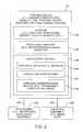
- FIG. 1illustrates a handheld device that may be used in conjunction with embodiments of the present invention
- FIG. 2is a schematic diagram of an illustrative handheld device with wireless capability that may be used in conjunction with embodiments of the present invention
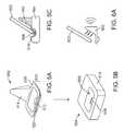
- FIGS. 3A-3Eare various perspective views of a stand-alone docking station particularly suitable for use with various embodiments of the present invention.
- FIG. 4illustrates an exemplary pinout that may be used for connectors such as the connectors in FIG. 3 as well as other connectors shown in these examples;
- FIGS. 5A , 5 B, and 5 Crespectively illustrate a removable dock insert that includes a reradiating antenna according to an embodiment of the present invention
- FIGS. 6A-6Dillustrate the capacitive coupling employed by embodiments of the present invention
- FIGS. 7A-7Billustrate another removable dock insert that includes a reradiating antenna according to an embodiment of the present invention
- FIGS. 8A and 8Billustrate an embodiment of a cable connector according to an embodiment of the present invention
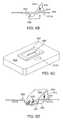
- FIGS. 9A and 9Brespectively show a perspective view and a cross-section view of an embodiment where a housing serves as an intermediate connector between a cable and a handheld device;
- FIG. 10illustrates a reradiating antenna connected to a boost circuit according to an embodiment of the present invention
- FIG. 11illustrates a reradiating antenna connected to a boost circuit that includes a processing circuit according to an embodiment of the present invention
- FIG. 12illustrates a docking station that includes a reradiating antenna and an inductive charging circuit for inductively charging a handheld device according to an embodiment of the present invention
- FIG. 13illustrates a flat surface docking station that includes a reradiating antenna and an inductive charging circuit for inductively charging a handheld device according to an embodiment of the present invention
- FIG. 14illustrates a docking station that includes an optical port for data transmission, a reradiating antenna, and an inductive charging circuit for inductively charging a handheld device according to an embodiment of the present invention
- FIG. 15illustrates an adapter that interfaces between a connector such as the 30 pin connector in FIG. 4 and a handheld device, and includes a reradiating antenna, an optical data interface, and an inductive charging circuit.
- FIG. 1illustrates a handheld device that may be used in conjunction with embodiments of the present invention.
- Handheld device 100includes housing 112 and includes at least one antenna (not shown).
- Housing 112which is sometimes referred to as a case, may be formed of any suitable materials, including plastic, wood, glass, ceramics, metal, or other suitable materials, or a combination of these materials.
- housing 112may be a dielectric or other low-conductivity material, so that the operation of conductive antenna elements that are located in proximity to housing 112 is not disrupted.
- housing 112may be formed from metal elements that serve as antenna elements.
- the antenna(s) in device 100may have a ground element (sometimes called a ground) and a resonant element (sometimes called a radiating element or antenna feed element).
- Antenna terminalswhich are sometimes referred to as the antenna's ground and feed terminals, are electrically connected to the antenna's ground and resonant element, respectively.
- Handheld device 100may have input-output devices such as a display screen 116 , buttons such as button 123 , user input control devices 118 such as button 119 , and input-output components such as port 120 and input-output jack 121 .
- Display screen 116may be, for example, a liquid crystal display (LCD), an organic light-emitting diode (OLED) display, a plasma display, or multiple displays that use one or more different display technologies. As shown in the example of FIG. 1 , display screens, such as display screen 116 , can be mounted on front face 122 of handheld electronic device 100 .
- displays such as display 116can be mounted on the rear face of handheld electronic device 100 , on a side of device 100 , on a flip-up portion of device 100 that is attached to a main body portion of device 100 by, for example, a hinge, or by using any other suitable mounting arrangement.
- a user of handheld device 100may supply input commands using user input interface 118 .
- User input interface 118may include buttons (e.g., alphanumeric keys, power on-off, power-on, power-off, and other specialized buttons), a touch pad, pointing stick, or other cursor control device, a touch screen (e.g., a touch screen implemented as part of screen 116 ), or any other suitable interface for controlling device 100 .
- buttonse.g., alphanumeric keys, power on-off, power-on, power-off, and other specialized buttons
- a touch pade.g., a touch pad implemented as part of screen 116
- touch screene.g., a touch screen implemented as part of screen 116
- user input interface 118may generally be formed on any suitable portion of handheld electronic device 100 .
- buttons and other user interface controlsmay be formed on the side of handheld electronic device 100 .
- Buttons and other user interface controlscan also be located on the top face, rear face, or other portion of device 100 .
- device 100can be controlled remotely (e.g., using an infrared remote control, a radio-frequency remote control such as a Bluetooth remote control).
- a speakernot shown
- a microphonenot shown
- Handheld device 100may have ports such as bus connector 120 and jack 121 that allow device 100 to interface with external components.
- Typical portsinclude power jacks to recharge a battery within device 100 or to operate device 100 from a direct current (DC) power supply, data ports to exchange data with external components such as a personal computer or peripheral, audio-visual jacks to drive headphones, a monitor, or other external audio-video equipment.
- DCdirect current
- the functions of some or all of these devices and the internal circuitry of handheld electronic devicescan be controlled using input interface 118 .
- Portable devicesmay be small portable computers such as those sometimes referred to as ultra-portables. Portable devices may also be somewhat smaller devices. Examples of smaller portable devices include wrist-watch devices, pendant devices, headphone and earpiece devices, and other wearable and miniature devices.
- One category of portable devicesis handheld devices. The invention is described in the context of handheld devices; however the invention may be implemented in any suitable portable electronic device.
- Handheld devicesmay be, for example, cellular telephones, media players with wireless communications capabilities, handheld computers (also sometimes called personal digital assistants), remote controllers, global positioning system (GPS) devices, and handheld gaming devices. Handheld devices may also be hybrid devices that combine the functionality of multiple conventional devices. Examples of hybrid handheld devices include a cellular telephone that includes media player functionality, a gaming device that includes a wireless communications capability, a cellular telephone that includes game and email functions, and a handheld device that receives email, supports mobile telephone calls, and supports web browsing. These are merely illustrative examples.
- FIG. 2is a schematic diagram of an illustrative handheld device with wireless capability that may be used in conjunction with embodiments of the present invention.
- Handheld device 100may be a mobile telephone, a mobile telephone with media player capabilities, a handheld computer, a remote control, a game player, a global positioning system (GPS) device, a combination of such devices, or any other suitable portable electronic device.
- GPSglobal positioning system
- handheld device 100includes storage 234 , which in turn may include one or more different types of storage such as hard disk drive storage, nonvolatile semiconductor memory (e.g., NAND and/or NOR varieties of flash memory, EPROM, EEPROM and/or ROM), volatile memory (e.g., SRAM, DRAM, battery-backed SRAM and/or battery-backed DRAM).
- storage 234may include one or more different types of storage such as hard disk drive storage, nonvolatile semiconductor memory (e.g., NAND and/or NOR varieties of flash memory, EPROM, EEPROM and/or ROM), volatile memory (e.g., SRAM, DRAM, battery-backed SRAM and/or battery-backed DRAM).
- Processing circuitry 236may be used to control the operation of device 100 .
- Processing circuitry 236may be based on a processor such as a microprocessor and/or a graphics processor and other suitable processor integrated circuits.
- Input-output devices 238may be used to allow data (e.g., text, video, audio) to be supplied to and from device 100 .
- Display screen 116 and user input interface 118 of FIG. 1are examples of input-output devices 238 .
- Input-output devices 238can include user input-output devices 240 such as buttons, touch screens, joysticks, click wheels, scrolling wheels, touch pads, key pads, keyboards, microphones, and cameras.
- a usercan control the operation of device 100 by supplying commands through user input devices 240 .
- Display and audio devices 242may include liquid-crystal display (LCD) screens, light-emitting diodes (LEDs), and other components that present visual information and status data.
- Display and audio devices 242may also include audio equipment such as microphone, speakers, and other apparatus.
- Display and audio devices 242may contain audio-video interface equipment such as jacks and other connectors for external headphones, monitors and other equipment.
- Wireless communications devices 244may include communications circuitry such as radio-frequency (RF) transceiver circuitry formed from one or more integrated circuits, power amplifier circuitry, passive RF components, antennas (internal and/or external) and other circuitry for handling RF wireless signals. Wireless signals can also be sent using light (e.g., using infrared communications).
- RFradio-frequency
- Paths 250may include wired and wireless paths.
- Accessories 246may include headphones (e.g., wired or wireless cellular headset and audio headphones) audio-video equipment (e.g., wireless speakers, Hi-Fi systems with integrated docking station, a game controller, or other equipment that receives and plays audio and video content), and stand-alone docking stations.
- Computing equipment 248may be a server from which songs, videos, or other media are downloaded wirelessly.
- Computing equipment 248may also be a local host (e.g., a user's own personal computer), from which the user obtains a wireless download of music or other media files.
- the wireless communications devices 244may be used to cover communications frequency bands such as the cellular telephone bands at 850 MHz, 900 MHz, 1800 MHz, and 1900 MHz, the global positioning system (GPS) band at 1575 MHz, data service bands such as the 3G data communications band at 2170 MHz band (commonly referred to as UMTS or Universal Mobile Telecommunications System), the WiFi® (IEEE 802.11) band at 2.4 GHz, and the Bluetooth® band at 2.4 GHz. These are merely illustrative communications bands over which wireless communications devices 244 may operate. Additional bands are expected to be deployed in the future as new wireless services are made available. Wireless communications devices 244 may be configured to operate over any suitable band or bands to cover any existing or new wireless services of interest.
- multiple antennasmay be provided in wireless communications devices 244 to cover more bands or one or more antennas may be provided with wide-bandwidth resonating element(s) to cover multiple communications bands of interest.
- An advantage of using a broadband antenna design that covers multiple communications bands of interestis that this type of approach makes it possible to reduce device complexity and cost and to minimize the volume within a handheld device that is allocated to antenna structures.
- a broadband designmay be used for one or more antennas in wireless communications devices 244 when it is desired to cover a relatively larger range of frequencies without providing numerous individual antennas or using a tunable antenna arrangement. If desired, a broadband antenna design may be made tunable to expand its bandwidth coverage or may be used in combination with additional antennas. In general, however, broadband designs tend to reduce or eliminate the need for multiple antennas and tunable configurations.
- FIGS. 3A-3Eare various perspective views of a stand-alone docking station 350 particularly suitable for use with various embodiments of the present invention.
- the stand-alone docking station 350allows a handheld device 352 to communicate with other media devices (not shown). By stand-alone, it is meant that it is physically separated from but operatively connectable to the media device (rather than being integrated therewith).
- housing 354is configured to enclose various electrical and structural components. Housing 354 is also configured to define the shape or form of docking station 350 . The shape may for example be substantially rectangular (as shown) or alternatively the shape may be circular, cubical, triangular, or any other suitable geometrical shape.
- housing 354may be formed by one or more housing components.
- housing 354may include an upper member 356 and a base member 358 that are attached using any suitable technique including for example screws, bolts, snaps, adhesives, and latches.
- opening 362for physically receiving a bottom portion 364 of handheld device 352 .
- opening 362has a shape that coincides with the shape of handheld device 352 , i.e., the bottom portion 364 of handheld device 352 may be inserted within opening 362 .
- the depth of opening 362is generally configured to keep the user interface of handheld device 352 exposed to the user.
- Opening 362may be vertical or sloped.
- opening 362is sloped so that handheld device 352 rests in a tilted position within docking station 350 .
- a tilted handheld device 352is easier to use (e.g., more ergonomic).
- the slopemay be widely varied. For example, it may tilt handheld device 252 about 5 to about 25 degrees and more particularly about 15 degrees.
- first connector 366for engaging a corresponding connector disposed on the bottom surface of handheld device 352 .
- the first connector 366is typically exposed through the housing 354 so that the handheld device connector can engage it.
- the handheld device connectoris a female port and the docking station connector 366 is a male plug.
- the plugis generally dimensioned for a tight fit within the port so as to secure the connection between the handheld device 352 and docking station 350 (e.g., no interlock except for connector).
- the first connector 366is generally sloped to a similar angle as the opening 362 so that engagement occurs between the first connector and the handheld device connector when handheld device 352 is slid into opening 362 .
- the sides of the opening 362serve as guides for placing the connectors in the correct engagement position.
- the first connector 366may be operatively coupled to one or more second connectors, each of which may be used to connect to some external device such as a media device, power plug and the like.
- the information passing through the first connector 366is directed to a single second connector while in other cases the information is split into multiple second connectors.
- the contacts of a single connector 366may be split into different connectors such as one or more data lines, power lines, audio lines and the like.
- the second connectorsmay be similar to the first connector or they may be different.
- multiple second connectorsmay be similar or they may be different from one another.
- the second connectorsare also exposed through the housing. In some cases, the second connectors are indirectly coupled to the docking station 350 .
- the second connectorsare directly coupled to the docking station 350 .
- theymay be attached to a portion of the docking station 350 without using a cord or cable.
- the second connectorsare free to be engaged directly to an external device or they may be coupled through a removable cord or cable.
- the corditself may be used to split information, i.e., a Y cord or cable.
- the internal components of docking station 350can best seen in FIG. 3C , which shows the docking station 350 with the top member 356 of the housing 354 removed.
- the internal componentsinclude at least a first connector 366 and a second connector 368 .
- the internal componentsmay also include an audio out connector 370 .
- the connectors 366 - 970are connected via a flex cable 372 .
- the connectors 366 - 370are positioned on one or more printed circuit boards 374 that are attached to the base member 358 of the housing 354 .
- the first connector 366is located at a position that places it within the opening 362 of the housing 354 (as shown in FIG. 3B ).
- the second connector 368 and the audio out connector 370are located at positions that place them within openings 376 at the backside of the housing 354 for external connection (as shown in FIG. 3D ). Also contained within the housing 354 is a ballast 378 enabling the docking station 350 to support handheld device 352 when inserted therein. An EMI shield may also be placed over the flex cable 372 to provide shielding.
- FIG. 4illustrates an exemplary pinout that may be used for connectors such as the connectors 366 - 370 and other connectors shown in these examples.
- these connectorsare multi-purpose 30 pin connectors with the pin assignment and function as outlined.
- One or more of the reserved pinsmay be connected to one or more antenna(s) inside the handheld device, thereby enabling direct electrical connection between the antenna(s) inside the handheld device and external components.
- This pin outadvantageously makes the handheld device compatible with different types of interfaces, such as the USB FireWire interfaces, is described more fully in application Ser. No. 11/519,541, filed Sep. 11, 2006, which disclosure is incorporated herein by reference in its entirety.
- FIGS. 5A , 5 B, and 5 Crespectively illustrate a removable dock insert that includes a reradiating antenna according to an embodiment of the present invention.
- FIG. 5Aillustrates an insert 502
- FIG. 5Billustrates a docking station 504
- FIG. 5Cillustrates a removable dock insert 502 inserted in docking station 504 and a handheld device 522 inserted in removable dock insert 502 .
- Removable dock insert 502 together with docking station 504provides a platform for quickly and easily coupling a wireless handheld device.
- Docking station 504may be a stand-alone unit that is configured to communicate with other devices or systems (e.g., a computer, a Hi-Fi system, a power source, or peripheral devices such as a monitor, a keyboard, and speakers) through wired (e.g., cables) or wireless (e.g., Bluetooth) connections. Alternatively, docking station 504 may be integrated directly into other devices or systems.
- devices or systemse.g., a computer, a Hi-Fi system, a power source, or peripheral devices such as a monitor, a keyboard, and speakers
- wirede.g., cables
- wirelesse.g., Bluetooth
- docking station 504includes a base 516 and an opening or slot 508 that is partially recessed in the top surface of base 516 .
- One embodiment of docking station 504 particularly suited for use with the some embodiments of the inventionis described in more detail with reference to FIGS. 3A-3E above. This and the other inserts described may be adjustable to provide mechanical support for various types of devices.
- the shape and size of opening 508is generally configured to coincide with the shape and size of the bottom end of one or more wireless handheld devices with a particular form factor.
- the docking stationis typically dedicated to handheld devices with such a form factor.
- Removable inserts, such as insert 502change the size and shape of opening 508 to enable docking station 504 to accommodate handheld devices with other form factors than that provided by opening 508 . While the openings in docking station 504 and dock insert 502 are shown to support a handheld device in an upright (e.g., generally vertical) position, they can also be configured to receive a handheld device along any other side (e.g., top left or right).
- a reradiating antennais embedded in removable dock insert 502 to improve the wireless communication with the wireless handheld device when it is docked in the docking station.
- the reradiating antenna(not shown) is housed in an upper portion 514 of insert 502 .
- a bottom portion 510 of insert 502is configured to fit opening 508 .
- Bottom portion 510includes a ring-shaped flat portion that rests over a surface region of docking station 504 extending along the perimeter of opening 508 .
- Bottom portion 510also includes a bowl-shaped portion 520 for receiving a handheld device.
- Bowl-shaped portion 520 of insert 502includes an opening 512 at its bottom to allow connector 506 of docking station 516 to protrude through when insert 502 is inserted in the docking station.
- FIG. 5Cshows a cross-section view of the docking station 504 with removable dock insert 502 inserted in the docking station, and a handheld device 522 coupled to docking station 504 and held in place by removable insert 502 .
- the antenna in dock insert 502serves as a reradiating antenna to facilitate wireless communication with handheld device 522 .
- the operative coupling of the antenna inside handheld device 522 with the reradiating antenna inside dock insert 502may be achieved in a number of ways, including through capacitive coupling, inductive coupling, and direct wire connection.
- FIGS. 6A-6Dillustrate the capacitive coupling employed by embodiments of the present invention. Specifically, FIG. 6A illustrates direct passive coupling while FIGS. 6B-6D illustrate an indirect form of passive coupling.
- FIG. 6Awhen handheld device 622 is inserted in dock insert 602 , the antenna in the handheld device comes in close proximity to the reradiating antenna in the dock insert, enabling coupling between the antennas as depicted by the arrows.
- FIG. 6Bshows a variation of the capacitive coupling embodiment wherein the antenna(s) in the handheld device are connected a capacitor plate 612 A of a capacitor 612 through a connector 606 .
- more than reradiating antenna and more than one capacitormay be used to enable multiple frequency bands (e.g., Bluetooth, WiFi, and cellular.)
- One or more wires 608 extending through docking station 604may be used to connect the appropriate pin(s) of connector 606 to capacitor plate(s) 612 A.
- one plate of capacitor 612is housed in docking station 604 and the other plate of capacitor 612 is housed in removable dock insert 602 and is connected to antenna 610 embedded in dock insert 602 .
- FIG. 6Cshows a top view of docking station 604 illustrating the location plate 612 A of capacitor 612 in docking station 604 .
- the upper portion of dock insert 602is removed in FIG. 6C to reveal the location of capacitor plate 612 inside docking station 604 .
- the embodiment depicted by FIGS. 6B and 6Cis advantageous in that the extent of the capacitive coupling is made independent of the location of the antenna(s) in the handheld device.
- FIG. 6Dshows yet another variation of the capacitive coupling embodiment where two capacitors are used.
- handheld device 622includes one or more antenna(s) 628 at a base of handheld device 622 near the connector.
- Antenna 628 in handheld device 622is coupled to reradiating antenna in removable insert 602 by first coupling to capacitor plate 624 , and then by coupling to capacitor 626 .
- a wire 630connects plate 624 to a plate of capacitor 626 .
- capacitor plate 624 and both plates of capacitor 626are formed as part of removable dock insert 602 so that no modification to the docking station is required.
- a direct wire connection between the antenna(s) in the handheld device and the reradiating antenna(s) in the removable dock insertmay be implemented, in accordance with anther embodiment of the invention.
- an openingmay be formed in an upper surface of docking station 604 through which wire(s) 608 may be directly connected to reradiating antenna(s) 610 .
- Inductive coupling techniquessimilar to above-described capacitive coupling techniques, may also be used to achieve electrical communication between the antenna(s) in the handheld device and the reradiating antenna(s) in the removable dock insert.
- the removable dock insert shown in FIGS. 5A-5C and 6 A- 6 Dhas the reradiating antenna(s) embedded in an upper portion of the insert, the invention is not limited as such.
- the reradiating antenna(s)may be embedded in the ring-shaped flat portion 518 of insert 502 in FIG. 5A .
- An exampleis shown in the following figure.
- FIGS. 7A-7Billustrate another removable dock insert that includes a reradiating antenna according to an embodiment of the present invention.
- FIG. 7Ashows an enlarged view of the ringed-shaped flat portion 718 of a removable dock insert 702 A in accordance with one embodiment of the invention.
- Dashed line 710depicts a conductive trace symbolizing one or more antenna(s).
- Antenna(s) 710are embedded in the flat portion 718 of removable insert 702 A.
- Flat portion 718may be made of non-conductive material such as plastic. Any one of the techniques for achieving operative coupling between the antenna(s) in a handheld device and reradiating antenna(s) 710 described above may also be used in the FIG. 7A embodiment.
- a capacitor plate 712 B to which antenna 710 is connectedmay be embedded in ring-shaped flat portion 718 , with a counterpart capacitor plate housed in the docking station in close proximity to capacitor plate 712 B.
- FIG. 7Bshows another variation where a PCB antenna 730 is attached to an under-side of the ring-shaped flat portion of a removable insert 702 B.
- known conductive painted circuit techniquesare integrated with the removable insert to implement the re-radiation antenna(s) of the removable dock insert.
- any known antenna implementation with a tuned antenna capable of repeating (reradiating) RF signals by proximity, as well as various ways of integrating such antenna(s) with a removable dock insert,is intended to fall within the scope of the invention.
- a removable housing adapted to either include a reradiating antenna or to be connected to an external reradiating antennamay be constructed for any wireless handheld device accessory, in accordance with embodiments of the invention.
- a docking stationit is common to not use a docking station but rather to use a cable for purposes of charging or data transfer.
- various embodiments of the present inventionincorporate a reradiating antenna in a cable housing. An example of this is shown in the following figures.
- FIGS. 8A and 8Billustrate an embodiment of a cable connector according to an embodiment of the present invention.
- FIG. 8Aillustrates a cable housing 606 connected to a cable 804 .
- Cable housing 606is formed to insert into slot 608 in wireless handheld device 802 .
- FIG. 8Bshows a cross-section view revealing relevant components inside removable housing 806 .
- a capacitor plate 810facilitates capacitive coupling between antenna(s) disposed at a base of a handheld device in close proximity to capacitor plate 810 .
- Capacitor plate 810is electrically connected to one or more reradiating antennas formed inside or outside removable housing 806 .
- the wire connectivity 814 to external reradiating antennasis eliminated.
- FIG. 8Ashows another example where wire connectivity 814 is eliminated.
- a reradiating antenna 812is wrapped around the cable wire portion 804 B of cable 804 .
- the FIG. 8B embodimentdepicts the case where capacitor plate 810 is connected to an external reradiating antenna (not shown).
- FIGS. 9A and 9Brespectively show a perspective view and a cross-section view of an embodiment where a housing 906 serves as an intermediate connector between a cable 912 and a handheld device 902 .
- This embodimentenables incorporating active components (such as amplifiers) in housing 906 .
- Poweris provided to the active components in housing 906 via cable 912 when cable 912 is connected to a device capable of providing power.
- the reradiating antenna(s)may be housed inside or outside housing 910 , and capacitive coupling may be used to operatively couple the antenna(s) in handheld device 902 to reradiating antenna(s), as described above.
- reradiating antennasin either an insert or cable connection
- other embodiments of the present inventionprovide reradiating antennas in other locations.
- the reradiating antenna or antennas and capacitor plates, if needed,are located in a docking station.
- passive couplingbetween an antenna in the handheld unit and reradiating antenna.
- This passive couplingmay be either capacitive or inductive in nature. Further, the two may be used in the same embodiment. For example, where there are two couplings employed, such as in the example of FIG. 4D , one can be inductive while the other is capacitive.
- the reradiating antennamay be coupled to an active gain circuit.
- a boost circuitis used to gain the signal on the reradiating antenna.
- Received signalsare amplified using a low-noise amplifier (LNA).
- Signals to be transmittedare amplified using a power amplifier (PA).
- LNAlow-noise amplifier
- PApower amplifier
- FIG. 10illustrates a reradiating antenna connected to a boosting circuit according to an embodiment of the present invention.
- This figureillustrates circuitry located on a handheld device as well as circuitry located in a docking station or an adapter such as an insert or cable adapter.
- low noise amplifier LNA 1 and power amplifier PA 1are located on the handheld device and are in communication with receiving and transmitting circuitry (not shown).
- This receiving and transmitting circuitrymay be connected to other circuitry, such as a Bluetooth circuit, such that the handheld device can be in communication with a Bluetooth headset.
- Boost circuitry LNA 2 and PA 2are located on the adapter or docking station.
- Voice or data signals generated on the handheld deviceare amplified by power amplifier PA 1 and placed on antenna A 1 .
- Antenna A 1is passively coupled to antenna A 2 via passive coupling capacitor C 1 .
- Signals received on antenna A 2are gained by a low noise amplifier LNA 2 and power amplifier PA 2 and placed on antenna A 2 , where it is transmitted to a network or other device, such as a cellular, local, or other type of network.
- Signalsmay be received at antenna A 2 from a cellular, local, or other network. Again, the signals are gained by low noise amplifier LNA 2 and power amplifier PA 2 and placed back on the antenna A 2 . The signals are then passively coupled to antenna A 1 via the past live coupling capacitor C 1 . The signals received at antenna A 1 are gained by the low noise amplifier LNA 1 and provided to handheld device receiving circuitry (not shown). At this point, they may be transmitted, for example to the Bluetooth headset described above.
- an LNA and PAare shown in this example, other embodiments of the present invention use only one amplifier.
- Various embodiments of the present invention that employ boost circuitsmay receive power in a number of ways. For example, power is readily available in most docking stations.
- An adaptermay receive power externally, or it may receive power via a connector in a docking station or cable to which it is connected.
- an adaptermay have a connector fitting that receives a connector from a docking station or cable, and another connector to provide a connection to the handheld device.
- the signals received and transmitted by the reradiating antennaare voice signals. In other embodiments, they are data signals carried by a cellular service. In still other embodiments, the signals are data signals from a local or wide-area wireless network such as IEEE 802.11a, b, g, or other standard or proprietary signaling protocols.
- the signalis received and amplified by the boost circuit, it is processed in some manner.
- This processingmay, for example, convert a data signal from one protocol to another.
- 802.11a data received from a networkis converted to 802.11g data and coupled to an antenna in the handheld device.
- 802.11g data coupled from the handheld deviceis converted to 802.11a data and transmitted to the network.
- An exampleis shown in the following figure.
- FIG. 11illustrates a reradiating antenna connected to a boosting circuit that includes a processing circuit according to an embodiment of the present invention.
- This figureincludes circuitry located on a handheld device as well as circuitry located in a docking station or an adapter, such as an insert or cable adapter.
- low noise amplifier LNA 1 and power amplifier PA 1are located on a handheld device.
- Low noise amplifier LNA 2 , power amplifier PA 2 , and the processing circuitsare located in a docking station or adapter.
- Signals transmitted by the handheld deviceare gained by the power amplifier PA 1 and placed on the antenna A 1 .
- the antenna A 1 in the handheld deviceis capacitively coupled to antenna A 2 in the docking station or adapter via the passive coupling capacitor C 1 .
- Signals received at antenna A 2are gained by the low noise amplifier LNA 2 and received by the processing circuits.
- the processing circuitsmay perform one or more of a number of functions.
- the processing circuitsmay receive data in a first format or protocol, and output data in a second format or protocol.
- the output of the processing circuitis gained by power amplifier PA 2 and provided on the antenna A 2 , where it is transmitted to a cellular, local, or other network.
- Signals received from a cellular, local, or other networkcan be received on antenna A 2 .
- the signalsare gained by the low noise amplifier LNA 2 , which again provides an upper to processing circuit.
- the processing circuitmay perform the inverse function that is performed on outgoing data. For example, data received in the second format or protocol may be converted to data in the first format or protocol.
- the out of the processing circuitis gained by power amplifier PA 2 and transmitted to antenna A 1 on the handheld device via antenna A 2 and the passive coupling capacitor C 1 .
- Signals received on antenna A 1are gained by low noise amplifier LNA 1 on the handheld device and provided to other receiving circuitry (not shown).
- this datamay be provided to a processing circuit using a USB or other type of connector.
- the processing circuitthen provides data to the power of amplifier PA, which transmits the data to the handheld device as before.
- Various embodiments of the present inventionmay use the passive and active coupling described above for other reasons than data and voice transmission.
- energy that may be used to charge a batterymay be coupled to a handheld device.
- another exemplary embodiment of the present inventionprovides inserts, cable connectors, and docking stations that are configured to include inductive charging.
- This techniquewhen combined with the capacitive coupling implementation of the reradiating antenna or antennas advantageously creates a wireless solution where both the wireless performance of the handheld device is improved and power charging capability is provided.
- An exampleis shown in the following figure.
- FIG. 12illustrates a docking station that includes a reradiating antenna and an inductive charging circuit for inductively charging a handheld device according to an embodiment of the present invention.
- the dock housingis configured to receive a handheld device. While the dock housing is shown to receive the handheld device in an upright position, other dock housing configurations for receiving the handheld device along its other sides are also possible.
- the dock housingis further configured to enable charging the battery of the handheld device through an inductive charge coupling mechanism, and to also provide improved wireless communication by integrating the reradiating antenna as shown.
- the charge circuitis connected between the inductive charge coupling mechanism and a port for receiving power.
- capacitive couplingis used for voice and data transfer between the handheld device and reradiating antenna.
- other couplingsuch as inductive
- the couplingmay be active.
- the charging circuitis shown as using inductive coupling. Alternately, capacitive coupling may be used for the charging circuit.
- the charging circuitgenerates a current in an inductive coupler, which in turn generates a current in the handheld device. This current is then used to charge a battery (not shown) on the handheld device. Similarly, voice or other data is capacitively coupled between the handheld device and the reradiating antenna via the capacitive coupler. In a typical embodiment of the present invention, these two circuits have the potential for interfering with each other. Accordingly, embodiments of the present invention typically take one or more measures to reduce this interference.
- the two circuits in the dock housingcan be shielded from each other using copper cladding, Faraday cages, or other such techniques.
- the circuitscan be arranged to operate at different times.
- the charging circuitcan be shut down when data is received or transmitted between the docking station and the handheld device.
- the frequency at which the charging circuit operatescan be varied in a frequency hopping manner. That is, by frequency hopping, spread spectrum techniques can be used. By varying the frequency of operation of the charging circuit as a function of time, the spectrum of the interfering signal can be spread over a wide range of frequencies and thereby reduced.
- a conventional receptacle that includes a connectoris no longer required. This is desirable as it removes the necessity of aligning the handheld device to the connector. It also eliminates a connector that may become fouled with particulate matter such as food crumbs. Moreover, it electrically isolates a user's handheld device from docking station circuitry. This is particularly desirable where physical security is a concern, such as on an airliner. In such a situation, a connector-free receptacle or cradle means the handheld device can be isolated from airplane circuitry.
- a docking station receptaclefor example the cradle from the above airplane example, or a simple flat surface for home or office use, can be used as a docking station receptacle.
- the docking stationmay include inductive or other charging.
- Voice and datamay be received by the docking station either wirelessly or via a wired connection and provided to a handheld device via a reradiating antenna that may be either passive or active.
- a reradiating antennamay be either passive or active.
- FIG. 13illustrates a docking station having a flat surface according to an embodiment of the present invention.
- the docking stationcan be as simple as a flat surface as shown here.
- the docking stationmay be built into a tabletop, or be formed as a device to sit on a desk, computer station, or other location.
- the handheld deviceis simply laid flat on the docking station for charging, synchronizing, or to make use of a reradiating antenna.
- the docking stationmay include a reradiating antenna, charging circuit, and other processing circuitry.
- Optional indicator LEDsmay indicate when data is being transferred, when charging is occurring, or other such events. If power is needed for the charging circuit, it may be provided by a separate power connector (not shown), or a via a data connector, such as the optional USB connector shown in this example. Data, for example music and video data, can be loaded on the handheld device. This data may be received wirelessly or via the USB connector and provided to the handheld device as shown in FIG. 11 . While the flat surface in this example is shown as a docking station, in other embodiments of the present invention, the flat surface may be an adapter that connects to any docking station or cable, as shown above
- datasuch as music and video data
- datais received either in a wired or wireless manner and coupled to a handheld device. In some situations this provides an undesirably slow transfer. Accordingly, various embodiments of the present invention utilize faster methods of data transfer.
- a specific embodimentuses an optical link to transfer data.
- Anotheremploys a wireless link.
- a faster data linksuch as one of the above can be combined in a docking station along with inductive charging and a passive or active reradiating antenna to provide a connector-free, and if desired, receptacle-free, docking station. An example is shown in the following figure.
- FIG. 14illustrates a docking station that includes an optical port for data transmission, a reradiating antenna, and a charging circuit that is capable of inductively charging a handheld device according to an embodiment of the present invention.
- This figureincludes a reradiating antenna that is capacitively coupled to an antenna on the handheld device via a capacitive coupler.
- a charging circuitcharges a battery in the handheld device via the inductive coupler.
- an optical circuitis included. Data is received and transmitted via the data I/O port by the optical circuit. The optical circuit transmits and receives data to and from the handheld device via a light pipe.
- the optical circuitis replaced by a wireless circuit, while in other embodiments, the optical circuit receives and transmits data to a cellular, local, or other network via a wireless circuit.
- the data I/O connectioncan be a connection such as a USB, FireWire, or a connector such as the 30 pin connector shown in FIG. 4 , or it can be a wireless connection, as described above.
- Handheld devicesthat are designed to be compatible with the above docking stations are distinct, connector-free devices. However, these devices, unless they also include a connector, are not compatible with legacy devices such as speaker systems, alarm clocks, and the like. Accordingly, it is desirable to provide an adapter to interface between a connector of a legacy device and these newer, connector-free devices.
- An example of such an adapteris shown in the following figure.
- FIG. 15illustrates an adapter that interfaces between a connector, such as the 30 pin connector in FIG. 4 , and a handheld device.
- the adapterincludes a reradiating antenna, an optical data interface, and an inductive charging circuit.
- This adaptercan be formed as a tray adapter such as those shown in FIGS. 5 , 6 , and 7 above, as a cable adapter such as those shown in FIGS. 8 and 9 above, or as other adapters consistent with embodiments of the present invention.
- the adapter housingcan include an optical circuit, charging circuit, and reradiating antenna.
- embodiments of the present inventionmay include any one or more of these, as well as other types of circuits and active and passive components.
- the charging circuit and optical circuitreceive power and data signals via the connector.
- the connectormay connect to a connector such as the 30 pin connector shown in FIG. 4 , though in other embodiments of the present invention, other connectors, such as USB or FireWire connectors can be used.
- This adaptermay have a receptacle to hold the handheld device for purposes of antenna or optical alignment, though no physical connector is required. Alternately, receptacle-free adapters may be used, such as a flat surface as shown in FIG. 13 .
- multi-frequency or communication protocolscan be either shared by a single reradiating antenna or implemented using multiple reradiating antennas.
- the removable housingmay be configured for use in many types of applications, such as a stand-alone or integrated docking station, a cable, or even in an aircraft where each passenger seat is equipped with docking station to enable cellular and other wireless and wired forms of communication with a passenger's wireless handheld device.
- an appropriate one of a variety of number of removable housings with embedded reradiating antenna(s) and/or inductive recharging capabilitymay be provided to the passenger by the aircraft attendant.
- a Bluetooth enabled earpiecethe passenger can use the cellular phone capability of the handheld device as it is docked in the docking station.
Landscapes
- Engineering & Computer Science (AREA)
- Computer Networks & Wireless Communication (AREA)
- Power Engineering (AREA)
- Physics & Mathematics (AREA)
- Electromagnetism (AREA)
- Telephone Set Structure (AREA)
- Support Of Aerials (AREA)
Abstract
Description
Claims (13)
Priority Applications (1)
| Application Number | Priority Date | Filing Date | Title |
|---|---|---|---|
| US11/970,504US8207906B2 (en) | 2007-01-08 | 2008-01-07 | Antenna insert |
Applications Claiming Priority (2)
| Application Number | Priority Date | Filing Date | Title |
|---|---|---|---|
| US88401407P | 2007-01-08 | 2007-01-08 | |
| US11/970,504US8207906B2 (en) | 2007-01-08 | 2008-01-07 | Antenna insert |
Publications (2)
| Publication Number | Publication Date |
|---|---|
| US20080165066A1 US20080165066A1 (en) | 2008-07-10 |
| US8207906B2true US8207906B2 (en) | 2012-06-26 |
Family
ID=39185289
Family Applications (1)
| Application Number | Title | Priority Date | Filing Date |
|---|---|---|---|
| US11/970,504Expired - Fee RelatedUS8207906B2 (en) | 2007-01-08 | 2008-01-07 | Antenna insert |
Country Status (6)
| Country | Link |
|---|---|
| US (1) | US8207906B2 (en) |
| EP (1) | EP2109915B1 (en) |
| CN (1) | CN101578734B (en) |
| AU (1) | AU2008204998B2 (en) |
| TW (1) | TWI398985B (en) |
| WO (1) | WO2008086312A1 (en) |
Cited By (15)
| Publication number | Priority date | Publication date | Assignee | Title |
|---|---|---|---|---|
| US20120176249A1 (en)* | 2011-01-10 | 2012-07-12 | Manjirnath Chatterjee | Proximity detection alarm for an inductively charged mobile computing device |
| US9448371B2 (en) | 2012-07-11 | 2016-09-20 | Commscope Connectivity Uk Limited | RFID-enabled optical adapter for use with a patch panel |
| US9496602B2 (en) | 2014-04-28 | 2016-11-15 | Apple Inc. | Plastic electronic device structures with embedded components |
| US9634709B2 (en) | 2014-09-04 | 2017-04-25 | Apple Inc. | Removable electronic device case with supplemental antenna element |
| US9654164B2 (en) | 2015-04-14 | 2017-05-16 | Apple Inc. | Removable electronic device case with supplemental wireless circuitry |
| US9722455B2 (en) | 2012-12-27 | 2017-08-01 | Nokia Technologies Oy | Controlling an application parameter |
| US9946297B2 (en) | 2014-09-30 | 2018-04-17 | Apple Inc. | Auxiliary electronic device attachable to a wearable electronic device |
| US9995883B2 (en)* | 2014-03-26 | 2018-06-12 | Commscope Technologies Llc | Optical adapter module with managed connectivity |
| US10461581B2 (en) | 2012-07-19 | 2019-10-29 | Nook Digital, Llc | Charging case for electronic devices |
| US10945713B2 (en) | 2016-11-23 | 2021-03-16 | C. R. Bard, Inc. | Single insertion multiple sample biopsy apparatus |
| US11088572B2 (en)* | 2018-11-16 | 2021-08-10 | Dexin Electronic Ltd. | Detachable charging pad |
| WO2021241766A1 (en)* | 2020-05-25 | 2021-12-02 | 엘지전자 주식회사 | Reradiation antenna and wireless charging device |
| EP4346009A1 (en)* | 2022-09-29 | 2024-04-03 | Meta Platforms Technologies, LLC | Adaptive impedance tuning for capacitive interconnects |
| US20240252741A1 (en)* | 2015-05-18 | 2024-08-01 | Tandem Diabetes Care, Inc. | Patch pump cartridge attachment |
| US12137887B2 (en) | 2017-11-30 | 2024-11-12 | C. R. Bard, Inc. | Sample container and coaxial introducer cannula for a biopsy apparatus |
Families Citing this family (31)
| Publication number | Priority date | Publication date | Assignee | Title |
|---|---|---|---|---|
| EP2109915B1 (en) | 2007-01-08 | 2013-12-04 | Apple Inc. | Antenna insert |
| US8527688B2 (en)* | 2008-09-26 | 2013-09-03 | Palm, Inc. | Extending device functionality amongst inductively linked devices |
| TWI450568B (en)* | 2008-11-20 | 2014-08-21 | Acer Inc | Motherboard and method for providing the motherboard with a wireless communication module |
| US8541974B2 (en)* | 2009-09-17 | 2013-09-24 | Qualcomm Incorporated | Movable magnetically resonant antenna for wireless charging |
| US8294418B2 (en)* | 2010-02-03 | 2012-10-23 | ConvenientPower, Ltd. | Power transfer device and method |
| US8301077B2 (en)* | 2009-09-24 | 2012-10-30 | ConvenientPower, Ltd | Antenna network for passive and active signal enhancement |
| US20110199045A1 (en)* | 2010-02-15 | 2011-08-18 | Convenientpower Hk Ltd | Power transfer device and method |
| US8964372B2 (en)* | 2010-03-30 | 2015-02-24 | Bose Corporation | Docking station |
| FI20105493A0 (en)* | 2010-05-07 | 2010-05-07 | Polar Electro Oy | power transmission |
| US20120081069A1 (en)* | 2010-09-30 | 2012-04-05 | I O Interconnect, Ltd. | Communication apparatus and signal processing method |
| TW201230490A (en) | 2010-12-02 | 2012-07-16 | Skycross Inc | Detachable antenna for radio communications device |
| US8645604B2 (en) | 2011-03-25 | 2014-02-04 | Apple Inc. | Device orientation based docking functions |
| TWI449279B (en)* | 2011-07-13 | 2014-08-11 | Asustek Comp Inc | Adapter module for portable electronic device |
| DE102012007922A1 (en)* | 2012-04-24 | 2013-10-24 | Peiker Acustic Gmbh & Co. Kg | Integration device and method for producing a wall of a receiving device |
| KR101967631B1 (en)* | 2012-06-19 | 2019-04-11 | 삼성전자주식회사 | Docking station |
| CN104049681B (en)* | 2013-03-15 | 2018-04-27 | 联想(北京)有限公司 | A kind of docking station and electronic equipment |
| US9577448B2 (en)* | 2013-07-30 | 2017-02-21 | Intel Corporation | Integration of wireless charging unit in a wireless device |
| US10084338B2 (en) | 2013-07-31 | 2018-09-25 | Intel Corporation | Wireless charging unit and coupler based docking combo for a wireless device |
| GB2517791B (en)* | 2013-09-03 | 2018-03-21 | Jaguar Land Rover Ltd | Antenna with device-shaped aperture locator for low-loss coupling |
| US9400529B2 (en)* | 2013-09-27 | 2016-07-26 | Apple Inc. | Electronic device having housing with embedded interconnects |
| KR102229009B1 (en)* | 2014-02-24 | 2021-03-17 | 삼성전자주식회사 | Displaying cradle and robbery state alarming method of cradled wearable device |
| WO2015126047A1 (en)* | 2014-02-24 | 2015-08-27 | Samsung Electronics Co., Ltd. | Cradle for exhibiting wearable device and method for warning stolen state of cradled wearable device |
| CN105098847B (en)* | 2014-04-24 | 2017-12-29 | 深圳市金溢科技股份有限公司 | A kind of efficiently batch wireless charging device and wireless charging method |
| US10050398B2 (en)* | 2014-07-31 | 2018-08-14 | Hewlett-Packard Development Company, L.P. | Dock connector |
| CN105933238A (en)* | 2016-06-30 | 2016-09-07 | 北京小米移动软件有限公司 | Wireless router |
| CN108200381A (en)* | 2017-09-29 | 2018-06-22 | 深圳市莫孚康技术有限公司 | Wireless image video transmission card and Related product |
| CN108417963A (en)* | 2018-02-05 | 2018-08-17 | 南昌黑鲨科技有限公司 | A kind of input equipment for intelligent terminal |
| US11114875B2 (en)* | 2018-05-16 | 2021-09-07 | Kanghong Zhang | Integrated charger and remote control |
| US10749243B2 (en) | 2018-10-29 | 2020-08-18 | Motorola Solutions, Inc. | Replaceable card for antenna frequency tuning |
| CN111490353B (en)* | 2019-01-25 | 2022-05-20 | 神讯电脑(昆山)有限公司 | Noise reduction structure and transmission base thereof |
| US12429912B2 (en)* | 2020-10-20 | 2025-09-30 | Future Dial, Inc. | Computing device docking station |
Citations (86)
| Publication number | Priority date | Publication date | Assignee | Title |
|---|---|---|---|---|
| US3191122A (en)* | 1961-12-01 | 1965-06-22 | Seismograph Servier Corp | Communication system for sielded areas |
| USD328277S (en) | 1990-04-12 | 1992-07-28 | Nokia Mobile Phones Ltd. | Tabletop charger for a mobile telephone |
| USD336631S (en) | 1991-10-09 | 1993-06-22 | Apple Computer, Inc. | Charger for laptop computer battery packs |
| US5233281A (en) | 1991-12-02 | 1993-08-03 | Wen-Chi Chiang | Replaceable cartridge type high speed nickel-cadmium battery charger |
| US5239669A (en)* | 1992-02-04 | 1993-08-24 | Trimble Navigation Limited | Coupler for eliminating a hardwire connection between a handheld global positioning system (GPS) receiver and a stationary remote antenna |
| US5280229A (en) | 1990-11-15 | 1994-01-18 | Bsg-Schalttechnik Gmbh & Co. Kg | Charging device for rechargeable batteries |
| US5357185A (en) | 1993-02-22 | 1994-10-18 | E Lead Electronic Co., Ltd. | Universal battery charger |
| EP0766339A2 (en) | 1995-09-26 | 1997-04-02 | Nokia Mobile Phones Ltd. | Apparatus for connecting a radiotelephone to an external antenna |
| US5668561A (en) | 1995-11-13 | 1997-09-16 | Motorola, Inc. | Antenna coupler |
| USD388764S (en) | 1996-03-18 | 1998-01-06 | Motorola, Inc. | Housing for a battery charging device |
| WO1998001919A2 (en) | 1996-07-05 | 1998-01-15 | Bosch Telecom Danmark A/S | A handheld apparatus having antenna means for emitting a radio signal, a holder therefor, and a method of transferring signals between said apparatus and holder |
| US5898290A (en) | 1995-09-07 | 1999-04-27 | Norand Corporation | Battery pack with capacity and pre-removal indicators |
| USD409987S (en) | 1998-07-31 | 1999-05-18 | Sharp Kabushiki Kaisha | Electronic organizer with docking station |
| USD411166S (en) | 1997-11-21 | 1999-06-22 | Sanyo Electric Co., Ltd. | Charger |
| US5920293A (en) | 1997-08-01 | 1999-07-06 | Motorola, Inc. | Radio frequency (RF) antenna coupler with an electrically extended ground plane |
| US5926005A (en) | 1997-04-21 | 1999-07-20 | Transcrypt International / E.F. Johnson Company | Charger for batteries and for devices having batteries |
| USD416536S (en) | 1999-02-16 | 1999-11-16 | Motorola, Inc. | Charging and programming dock |
| USD419160S (en) | 1998-05-14 | 2000-01-18 | Northrop Grumman Corporation | Personal communications unit docking station |
| US6042414A (en) | 1997-11-14 | 2000-03-28 | Intermec Ip Corp. | Vehicle dock for portable data collection terminal |
| USD422556S (en) | 1998-10-09 | 2000-04-11 | Matsushita Electric Industrial Co., Ltd. | Contactless charger |
| USD427970S (en) | 1999-07-07 | 2000-07-11 | Sage George E | Expandable battery charger housing |
| US6115247A (en) | 1998-04-30 | 2000-09-05 | Hewlett-Packard Company | Method and apparatus for aligning portable computers of varying widths in a variable width docking station |
| WO2000060450A1 (en) | 1999-04-07 | 2000-10-12 | Khyber Technologies Corporation | Portable computing, communication and entertainment device with central processor carried in a detachable handset |
| US6193546B1 (en) | 1999-03-16 | 2001-02-27 | Ericsson Inc. | Support assembly for personal electronic device and method for using the same |
| USD439908S1 (en) | 2000-03-31 | 2001-04-03 | Shai N. Gozani | Docking station for a hand-held monitor |
| USD440542S1 (en) | 1996-11-04 | 2001-04-17 | Palm Computing, Inc. | Pocket-size organizer with stand |
| EP1104150A2 (en) | 1999-11-23 | 2001-05-30 | Lucent Technologies Inc. | Cordless telephone with MP3 player capability |
| USD444124S1 (en) | 2000-10-28 | 2001-06-26 | Motorola, Inc. | Desktop charger |
| USD444121S1 (en) | 2000-04-14 | 2001-06-26 | Motorola, Inc. | Desktop charger |
| US6301106B1 (en) | 1998-10-26 | 2001-10-09 | Hewlett-Packard Company | Docking station having a plurality of adapter trays for a plurality of portable computers |
| USD450707S1 (en) | 1999-11-30 | 2001-11-20 | Palm, Inc. | Communication accessory device for handheld computer |
| US6341218B1 (en) | 1999-12-06 | 2002-01-22 | Cellport Systems, Inc. | Supporting and connecting a portable phone |
| US6344727B1 (en) | 2001-03-05 | 2002-02-05 | Motorola, Inc. | Charger having a data store and data link |
| US20020024794A1 (en) | 2000-07-20 | 2002-02-28 | Yao-Chung Lin | Cradle |
| USD454332S1 (en) | 2000-12-11 | 2002-03-12 | Kabushiki Kaisha Toshiba | Electric charger for radio telephones |
| US20020032042A1 (en) | 2000-02-18 | 2002-03-14 | Poplawsky Ralph C. | Exporting controls to an external device connected to a portable phone system |
| US6394300B1 (en) | 2000-04-17 | 2002-05-28 | Daniel F. Bosy | Lock for compartment cover |
| USD459299S1 (en) | 1997-11-25 | 2002-06-25 | Swatch Ag (Swatch Sa) (Swatch Ltd.) | Telephone charging unit module |
| US20020103008A1 (en) | 2001-01-29 | 2002-08-01 | Rahn Michael D. | Cordless communication between PDA and host computer using cradle |
| USD461476S1 (en) | 2000-09-29 | 2002-08-13 | Palm, Inc. | Cable dock module with sync button for a PDA device |
| US20020115480A1 (en) | 2001-02-13 | 2002-08-22 | Huang Chih Chen | Adapter set |
| USD463361S1 (en) | 2001-03-02 | 2002-09-24 | Nokia Mobile Phones Ltd. | Desktop charger/desktop stand |
| US20020163780A1 (en) | 2001-05-02 | 2002-11-07 | Palm, Inc. | Synchronization cradle with expansion card slots |
| US6483698B1 (en) | 1998-11-27 | 2002-11-19 | Hewlett-Packard Company | Cradle for supporting a PDA and similar portable electronic devices |
| US20020173273A1 (en) | 2001-05-16 | 2002-11-21 | Fullaudio Corporation | Proximity synchronization of audio content among multiple playback and storage devices |
| USD466122S1 (en) | 2000-10-31 | 2002-11-26 | Delphi Technologies, Inc. | Elements of docking station for a portable computer device |
| US20020186319A1 (en) | 2001-06-05 | 2002-12-12 | Eastman Kodak Company | Docking station assembly for transmitting digital files |
| USD468305S1 (en) | 2002-04-30 | 2003-01-07 | Motorola, Inc. | Base for receiving a portable communication device or for receiving similar articles |
| US6524240B1 (en) | 2000-11-22 | 2003-02-25 | Medwave, Inc. | Docking station for portable medical devices |
| USD472900S1 (en) | 2001-02-15 | 2003-04-08 | Kabushiki Kaisha Toshiba | Stand for electronic computers |
| US20030097379A1 (en) | 2001-11-16 | 2003-05-22 | Sonicblue, Inc. | Remote-directed management of media content |
| US20030148740A1 (en) | 2000-12-28 | 2003-08-07 | William Yau | Handset holder |
| US20030198015A1 (en) | 2002-04-19 | 2003-10-23 | Edwin Vogt | Mobile docking station |
| US6716058B2 (en) | 2001-08-21 | 2004-04-06 | Samsung Electronics Co., Ltd. | Cradle device of portable terminal |
| USD495336S1 (en) | 2003-04-25 | 2004-08-31 | Apple Computer, Inc. | Docking station |
| US6798647B2 (en) | 2001-07-16 | 2004-09-28 | Hewlett-Packard Development Company, L.P. | Portable computer with integrated PDA I/O docking cradle |
| WO2004084413A2 (en) | 2003-03-17 | 2004-09-30 | Simple Devices, Inc. | System and method for activation of portable and mobile media player devices for wireless lan services |
| US20040195305A1 (en) | 2002-11-19 | 2004-10-07 | Leslie Dotson | Foldable key assembly |
| US6813528B1 (en) | 1998-03-09 | 2004-11-02 | Samsung Electronics Co., Ltd. | Apparatus and method for outputting audio signal of laptop computer coupled with docking station |
| US20040224638A1 (en) | 2003-04-25 | 2004-11-11 | Apple Computer, Inc. | Media player system |
| US6831609B2 (en)* | 2002-12-23 | 2004-12-14 | Cingular Wireless, Llc | Auxiliary antenna for wireless handset |
| US20040267825A1 (en) | 2003-06-25 | 2004-12-30 | Microsoft Corporation | Media library synchronizer |
| US20050042999A1 (en)* | 2003-08-22 | 2005-02-24 | Rappaport Theodore S. | Broadband repeater with security for ultrawideband technologies |
| US20050047099A1 (en) | 2003-08-26 | 2005-03-03 | Belkin Corporation | Universal serial bus hub and method of manufacturing same |
| US6898080B2 (en) | 2002-01-07 | 2005-05-24 | Hewlett-Packard Development Company, L.P. | Portable computer docking station with movable electrical interface |
| US6996369B2 (en)* | 2002-08-22 | 2006-02-07 | Eagle Broadband, Inc. | Repeater for a satellite phone |
| US6994575B1 (en) | 2004-12-22 | 2006-02-07 | Motorola, Inc. | Desktop charger with adjustable connector module |
| US7014486B1 (en) | 2004-12-07 | 2006-03-21 | High Tech Computer, Corp. | Recoverable connector structure and cradle having the same |
| US7030819B2 (en)* | 2003-08-27 | 2006-04-18 | Uniden Corporation | Re-radiating antenna system |
| USD525616S1 (en) | 2004-12-23 | 2006-07-25 | Apple Computer, Inc. | Stand |
| WO2006080659A1 (en) | 2005-01-28 | 2006-08-03 | Diasonic Technology Co., Ltd. | Mp3 playing and charging system comprising a docking station having an adapter for installing mp3 and a dynamic speaker |
| US20060181840A1 (en) | 2005-01-05 | 2006-08-17 | Jonatan Cvetko | Cradle for portable devices on a vehicle |
| US20060250764A1 (en) | 2005-05-09 | 2006-11-09 | Apple Computer, Inc. | Universal docking station for hand held electronic devices |
| US7149514B1 (en)* | 1997-07-30 | 2006-12-12 | Bellsouth Intellectual Property Corp. | Cellular docking station |
| US20070002533A1 (en) | 2005-06-30 | 2007-01-04 | Kogan Eduard M | Reconfigurable mobile device docking cradle |
| US7238042B2 (en) | 2004-12-24 | 2007-07-03 | Hong Fu Jin Precision Industry (Shenzheng) Co., Ltd. | Support assembly for portable device |
| USD551212S1 (en) | 2005-08-24 | 2007-09-18 | Apple Inc. | Dock insert |
| USD551213S1 (en) | 2005-08-24 | 2007-09-18 | Apple Inc. | Dock insert |
| USD552085S1 (en) | 2005-08-24 | 2007-10-02 | Apple Inc. | Dock insert |
| USD558738S1 (en) | 2005-08-24 | 2008-01-01 | Apple Inc. | Docking station |
| USD558739S1 (en) | 2005-08-24 | 2008-01-01 | Apple Inc. | Docking station |
| US7381095B2 (en) | 2005-06-20 | 2008-06-03 | Belkin International, Inc. | Multi-standard connection hub and method of manufacturing same |
| WO2008086312A1 (en) | 2007-01-08 | 2008-07-17 | Apple Inc. | Antenna insert |
| US20080304688A1 (en) | 1999-04-07 | 2008-12-11 | Rajendra Kumar | Docking display station with docking port for retaining a hands-free headset therein |
| US7629943B2 (en)* | 2007-02-14 | 2009-12-08 | Keystone Technology Solutions, Llc | Electronic monitoring systems, shipment container monitoring systems and methods of monitoring a shipment in a container |
| US7673083B2 (en) | 2004-04-27 | 2010-03-02 | Apple Inc. | Method and system for controlling video selection and playback in a portable media player |
- 2008
- 2008-01-07EPEP08705744.4Apatent/EP2109915B1/ennot_activeNot-in-force
- 2008-01-07TWTW097100636Apatent/TWI398985B/ennot_activeIP Right Cessation
- 2008-01-07CNCN200880001897.2Apatent/CN101578734B/ennot_activeExpired - Fee Related
- 2008-01-07USUS11/970,504patent/US8207906B2/ennot_activeExpired - Fee Related
- 2008-01-07AUAU2008204998Apatent/AU2008204998B2/ennot_activeCeased
- 2008-01-07WOPCT/US2008/050439patent/WO2008086312A1/enactiveApplication Filing
Patent Citations (90)
| Publication number | Priority date | Publication date | Assignee | Title |
|---|---|---|---|---|
| US3191122A (en)* | 1961-12-01 | 1965-06-22 | Seismograph Servier Corp | Communication system for sielded areas |
| USD328277S (en) | 1990-04-12 | 1992-07-28 | Nokia Mobile Phones Ltd. | Tabletop charger for a mobile telephone |
| US5280229A (en) | 1990-11-15 | 1994-01-18 | Bsg-Schalttechnik Gmbh & Co. Kg | Charging device for rechargeable batteries |
| USD336631S (en) | 1991-10-09 | 1993-06-22 | Apple Computer, Inc. | Charger for laptop computer battery packs |
| US5233281A (en) | 1991-12-02 | 1993-08-03 | Wen-Chi Chiang | Replaceable cartridge type high speed nickel-cadmium battery charger |
| US5239669A (en)* | 1992-02-04 | 1993-08-24 | Trimble Navigation Limited | Coupler for eliminating a hardwire connection between a handheld global positioning system (GPS) receiver and a stationary remote antenna |
| US5357185A (en) | 1993-02-22 | 1994-10-18 | E Lead Electronic Co., Ltd. | Universal battery charger |
| US5898290A (en) | 1995-09-07 | 1999-04-27 | Norand Corporation | Battery pack with capacity and pre-removal indicators |
| EP0766339A2 (en) | 1995-09-26 | 1997-04-02 | Nokia Mobile Phones Ltd. | Apparatus for connecting a radiotelephone to an external antenna |
| US5668561A (en) | 1995-11-13 | 1997-09-16 | Motorola, Inc. | Antenna coupler |
| USD388764S (en) | 1996-03-18 | 1998-01-06 | Motorola, Inc. | Housing for a battery charging device |
| WO1998001919A2 (en) | 1996-07-05 | 1998-01-15 | Bosch Telecom Danmark A/S | A handheld apparatus having antenna means for emitting a radio signal, a holder therefor, and a method of transferring signals between said apparatus and holder |
| USD440542S1 (en) | 1996-11-04 | 2001-04-17 | Palm Computing, Inc. | Pocket-size organizer with stand |
| US5926005A (en) | 1997-04-21 | 1999-07-20 | Transcrypt International / E.F. Johnson Company | Charger for batteries and for devices having batteries |
| US7363034B2 (en)* | 1997-07-30 | 2008-04-22 | At&T Delaware Intellectual Property, Inc. | Cellular docking station |
| US7149514B1 (en)* | 1997-07-30 | 2006-12-12 | Bellsouth Intellectual Property Corp. | Cellular docking station |
| US5920293A (en) | 1997-08-01 | 1999-07-06 | Motorola, Inc. | Radio frequency (RF) antenna coupler with an electrically extended ground plane |
| US6042414A (en) | 1997-11-14 | 2000-03-28 | Intermec Ip Corp. | Vehicle dock for portable data collection terminal |
| USD411166S (en) | 1997-11-21 | 1999-06-22 | Sanyo Electric Co., Ltd. | Charger |
| USD459299S1 (en) | 1997-11-25 | 2002-06-25 | Swatch Ag (Swatch Sa) (Swatch Ltd.) | Telephone charging unit module |
| US6813528B1 (en) | 1998-03-09 | 2004-11-02 | Samsung Electronics Co., Ltd. | Apparatus and method for outputting audio signal of laptop computer coupled with docking station |
| US6115247A (en) | 1998-04-30 | 2000-09-05 | Hewlett-Packard Company | Method and apparatus for aligning portable computers of varying widths in a variable width docking station |
| USD419160S (en) | 1998-05-14 | 2000-01-18 | Northrop Grumman Corporation | Personal communications unit docking station |
| USD409987S (en) | 1998-07-31 | 1999-05-18 | Sharp Kabushiki Kaisha | Electronic organizer with docking station |
| USD422556S (en) | 1998-10-09 | 2000-04-11 | Matsushita Electric Industrial Co., Ltd. | Contactless charger |
| US6301106B1 (en) | 1998-10-26 | 2001-10-09 | Hewlett-Packard Company | Docking station having a plurality of adapter trays for a plurality of portable computers |
| US6483698B1 (en) | 1998-11-27 | 2002-11-19 | Hewlett-Packard Company | Cradle for supporting a PDA and similar portable electronic devices |
| USD416536S (en) | 1999-02-16 | 1999-11-16 | Motorola, Inc. | Charging and programming dock |
| US6193546B1 (en) | 1999-03-16 | 2001-02-27 | Ericsson Inc. | Support assembly for personal electronic device and method for using the same |
| US20080304688A1 (en) | 1999-04-07 | 2008-12-11 | Rajendra Kumar | Docking display station with docking port for retaining a hands-free headset therein |
| WO2000060450A1 (en) | 1999-04-07 | 2000-10-12 | Khyber Technologies Corporation | Portable computing, communication and entertainment device with central processor carried in a detachable handset |
| USD427970S (en) | 1999-07-07 | 2000-07-11 | Sage George E | Expandable battery charger housing |
| EP1104150A2 (en) | 1999-11-23 | 2001-05-30 | Lucent Technologies Inc. | Cordless telephone with MP3 player capability |
| USD450707S1 (en) | 1999-11-30 | 2001-11-20 | Palm, Inc. | Communication accessory device for handheld computer |
| US6341218B1 (en) | 1999-12-06 | 2002-01-22 | Cellport Systems, Inc. | Supporting and connecting a portable phone |
| US20020032042A1 (en) | 2000-02-18 | 2002-03-14 | Poplawsky Ralph C. | Exporting controls to an external device connected to a portable phone system |
| USD439908S1 (en) | 2000-03-31 | 2001-04-03 | Shai N. Gozani | Docking station for a hand-held monitor |
| USD444121S1 (en) | 2000-04-14 | 2001-06-26 | Motorola, Inc. | Desktop charger |
| US6394300B1 (en) | 2000-04-17 | 2002-05-28 | Daniel F. Bosy | Lock for compartment cover |
| US20020024794A1 (en) | 2000-07-20 | 2002-02-28 | Yao-Chung Lin | Cradle |
| USD461476S1 (en) | 2000-09-29 | 2002-08-13 | Palm, Inc. | Cable dock module with sync button for a PDA device |
| USD444124S1 (en) | 2000-10-28 | 2001-06-26 | Motorola, Inc. | Desktop charger |
| USD466122S1 (en) | 2000-10-31 | 2002-11-26 | Delphi Technologies, Inc. | Elements of docking station for a portable computer device |
| US6524240B1 (en) | 2000-11-22 | 2003-02-25 | Medwave, Inc. | Docking station for portable medical devices |
| USD454332S1 (en) | 2000-12-11 | 2002-03-12 | Kabushiki Kaisha Toshiba | Electric charger for radio telephones |
| US20030148740A1 (en) | 2000-12-28 | 2003-08-07 | William Yau | Handset holder |
| US20020103008A1 (en) | 2001-01-29 | 2002-08-01 | Rahn Michael D. | Cordless communication between PDA and host computer using cradle |
| US20020115480A1 (en) | 2001-02-13 | 2002-08-22 | Huang Chih Chen | Adapter set |
| USD472900S1 (en) | 2001-02-15 | 2003-04-08 | Kabushiki Kaisha Toshiba | Stand for electronic computers |
| USD463361S1 (en) | 2001-03-02 | 2002-09-24 | Nokia Mobile Phones Ltd. | Desktop charger/desktop stand |
| US6344727B1 (en) | 2001-03-05 | 2002-02-05 | Motorola, Inc. | Charger having a data store and data link |
| US20020163780A1 (en) | 2001-05-02 | 2002-11-07 | Palm, Inc. | Synchronization cradle with expansion card slots |
| US20020173273A1 (en) | 2001-05-16 | 2002-11-21 | Fullaudio Corporation | Proximity synchronization of audio content among multiple playback and storage devices |
| US20020186319A1 (en) | 2001-06-05 | 2002-12-12 | Eastman Kodak Company | Docking station assembly for transmitting digital files |
| US7075579B2 (en) | 2001-06-05 | 2006-07-11 | Eastman Kodak Company | Docking station assembly for transmitting digital files |
| US6798647B2 (en) | 2001-07-16 | 2004-09-28 | Hewlett-Packard Development Company, L.P. | Portable computer with integrated PDA I/O docking cradle |
| US6961237B2 (en) | 2001-07-16 | 2005-11-01 | Hewlett-Packard Development Company, L.P. | Portable computer with integrated PDA I/O docking cradle |
| US6716058B2 (en) | 2001-08-21 | 2004-04-06 | Samsung Electronics Co., Ltd. | Cradle device of portable terminal |
| US20030097379A1 (en) | 2001-11-16 | 2003-05-22 | Sonicblue, Inc. | Remote-directed management of media content |
| US6898080B2 (en) | 2002-01-07 | 2005-05-24 | Hewlett-Packard Development Company, L.P. | Portable computer docking station with movable electrical interface |
| US20030198015A1 (en) | 2002-04-19 | 2003-10-23 | Edwin Vogt | Mobile docking station |
| USD468305S1 (en) | 2002-04-30 | 2003-01-07 | Motorola, Inc. | Base for receiving a portable communication device or for receiving similar articles |
| US6996369B2 (en)* | 2002-08-22 | 2006-02-07 | Eagle Broadband, Inc. | Repeater for a satellite phone |
| US20040195305A1 (en) | 2002-11-19 | 2004-10-07 | Leslie Dotson | Foldable key assembly |
| US6831609B2 (en)* | 2002-12-23 | 2004-12-14 | Cingular Wireless, Llc | Auxiliary antenna for wireless handset |
| WO2004084413A2 (en) | 2003-03-17 | 2004-09-30 | Simple Devices, Inc. | System and method for activation of portable and mobile media player devices for wireless lan services |
| USD495336S1 (en) | 2003-04-25 | 2004-08-31 | Apple Computer, Inc. | Docking station |
| US20040224638A1 (en) | 2003-04-25 | 2004-11-11 | Apple Computer, Inc. | Media player system |
| US20040267825A1 (en) | 2003-06-25 | 2004-12-30 | Microsoft Corporation | Media library synchronizer |
| US20050042999A1 (en)* | 2003-08-22 | 2005-02-24 | Rappaport Theodore S. | Broadband repeater with security for ultrawideband technologies |
| US20050047099A1 (en) | 2003-08-26 | 2005-03-03 | Belkin Corporation | Universal serial bus hub and method of manufacturing same |
| US7030819B2 (en)* | 2003-08-27 | 2006-04-18 | Uniden Corporation | Re-radiating antenna system |
| US7673083B2 (en) | 2004-04-27 | 2010-03-02 | Apple Inc. | Method and system for controlling video selection and playback in a portable media player |
| US7014486B1 (en) | 2004-12-07 | 2006-03-21 | High Tech Computer, Corp. | Recoverable connector structure and cradle having the same |
| US6994575B1 (en) | 2004-12-22 | 2006-02-07 | Motorola, Inc. | Desktop charger with adjustable connector module |
| USD525616S1 (en) | 2004-12-23 | 2006-07-25 | Apple Computer, Inc. | Stand |
| US7238042B2 (en) | 2004-12-24 | 2007-07-03 | Hong Fu Jin Precision Industry (Shenzheng) Co., Ltd. | Support assembly for portable device |
| US20060181840A1 (en) | 2005-01-05 | 2006-08-17 | Jonatan Cvetko | Cradle for portable devices on a vehicle |
| WO2006080659A1 (en) | 2005-01-28 | 2006-08-03 | Diasonic Technology Co., Ltd. | Mp3 playing and charging system comprising a docking station having an adapter for installing mp3 and a dynamic speaker |
| US20060250764A1 (en) | 2005-05-09 | 2006-11-09 | Apple Computer, Inc. | Universal docking station for hand held electronic devices |
| US7381095B2 (en) | 2005-06-20 | 2008-06-03 | Belkin International, Inc. | Multi-standard connection hub and method of manufacturing same |
| US20070002533A1 (en) | 2005-06-30 | 2007-01-04 | Kogan Eduard M | Reconfigurable mobile device docking cradle |
| US7480138B2 (en) | 2005-06-30 | 2009-01-20 | Symbol Technologies, Inc. | Reconfigurable mobile device docking cradle |
| USD551213S1 (en) | 2005-08-24 | 2007-09-18 | Apple Inc. | Dock insert |
| USD552085S1 (en) | 2005-08-24 | 2007-10-02 | Apple Inc. | Dock insert |
| USD558738S1 (en) | 2005-08-24 | 2008-01-01 | Apple Inc. | Docking station |
| USD558739S1 (en) | 2005-08-24 | 2008-01-01 | Apple Inc. | Docking station |
| USD551212S1 (en) | 2005-08-24 | 2007-09-18 | Apple Inc. | Dock insert |
| WO2008086312A1 (en) | 2007-01-08 | 2008-07-17 | Apple Inc. | Antenna insert |
| US7629943B2 (en)* | 2007-02-14 | 2009-12-08 | Keystone Technology Solutions, Llc | Electronic monitoring systems, shipment container monitoring systems and methods of monitoring a shipment in a container |
Non-Patent Citations (5)
| Title |
|---|
| "iPodDock-iPod Cradle," www.bookendzdocks.com-bookendz-dock-cradle.html, downloaded Feb. 27, 2003. |
| European Search Report for European Patent Application No. 08705744.4, mailed on May 5, 2011, 5 pages. |
| Examiner's First Report for Australian Patent Application No. 2008204998, mailed on Aug. 11, 2010, 4 pages. |
| Hughes, Judie, "Atech Flash Technology iDuo iPod Dock and Card Reader," Gadgeteer Hands on Review, 9 pages, Nov. 17, 2005. |
| Sinitsyn, "Synchronization Framework for Personal Mobile Servers," Pervasive Computing and Communications Workshops (PERCOMW'04), Proceedings of the Second IEEE Annual Conference, Piscataway, NJ, USA, IEEE, Mar. 14, 2004, pp. 208-212. |
Cited By (21)
| Publication number | Priority date | Publication date | Assignee | Title |
|---|---|---|---|---|
| US8525688B2 (en)* | 2011-01-10 | 2013-09-03 | Palm, Inc. | Proximity detection alarm for an inductively charged mobile computing device |
| US20120176249A1 (en)* | 2011-01-10 | 2012-07-12 | Manjirnath Chatterjee | Proximity detection alarm for an inductively charged mobile computing device |
| US9448371B2 (en) | 2012-07-11 | 2016-09-20 | Commscope Connectivity Uk Limited | RFID-enabled optical adapter for use with a patch panel |
| US9946037B2 (en) | 2012-07-11 | 2018-04-17 | Commscope Connectivity Uk Limited | RFID-enabled optical adapter for use with a patch panel |
| US10461581B2 (en) | 2012-07-19 | 2019-10-29 | Nook Digital, Llc | Charging case for electronic devices |
| US9722455B2 (en) | 2012-12-27 | 2017-08-01 | Nokia Technologies Oy | Controlling an application parameter |
| US9995883B2 (en)* | 2014-03-26 | 2018-06-12 | Commscope Technologies Llc | Optical adapter module with managed connectivity |
| US10509177B2 (en) | 2014-03-26 | 2019-12-17 | Commscope Technologies Llc | Optical adapter module with managed connectivity |
| US9496602B2 (en) | 2014-04-28 | 2016-11-15 | Apple Inc. | Plastic electronic device structures with embedded components |
| US9634709B2 (en) | 2014-09-04 | 2017-04-25 | Apple Inc. | Removable electronic device case with supplemental antenna element |
| US10599181B2 (en) | 2014-09-30 | 2020-03-24 | Apple Inc. | Auxiliary electronic device attachable to a wearable electronic device |
| US9946297B2 (en) | 2014-09-30 | 2018-04-17 | Apple Inc. | Auxiliary electronic device attachable to a wearable electronic device |
| US9654164B2 (en) | 2015-04-14 | 2017-05-16 | Apple Inc. | Removable electronic device case with supplemental wireless circuitry |
| US20240252741A1 (en)* | 2015-05-18 | 2024-08-01 | Tandem Diabetes Care, Inc. | Patch pump cartridge attachment |
| US12343496B2 (en)* | 2015-05-18 | 2025-07-01 | Tandem Diabetes Care, Inc | Patch pump cartridge attachment |
| US10945713B2 (en) | 2016-11-23 | 2021-03-16 | C. R. Bard, Inc. | Single insertion multiple sample biopsy apparatus |
| US11786226B2 (en) | 2016-11-23 | 2023-10-17 | C.R. Bard, Inc. | Single insertion multiple sample biopsy apparatus |
| US12137887B2 (en) | 2017-11-30 | 2024-11-12 | C. R. Bard, Inc. | Sample container and coaxial introducer cannula for a biopsy apparatus |
| US11088572B2 (en)* | 2018-11-16 | 2021-08-10 | Dexin Electronic Ltd. | Detachable charging pad |
| WO2021241766A1 (en)* | 2020-05-25 | 2021-12-02 | 엘지전자 주식회사 | Reradiation antenna and wireless charging device |
| EP4346009A1 (en)* | 2022-09-29 | 2024-04-03 | Meta Platforms Technologies, LLC | Adaptive impedance tuning for capacitive interconnects |
Also Published As
| Publication number | Publication date |
|---|---|
| AU2008204998A1 (en) | 2008-07-17 |
| HK1135516A1 (en) | 2010-06-04 |
| TWI398985B (en) | 2013-06-11 |
| US20080165066A1 (en) | 2008-07-10 |
| TW200838027A (en) | 2008-09-16 |
| CN101578734B (en) | 2014-08-20 |
| EP2109915B1 (en) | 2013-12-04 |
| AU2008204998B2 (en) | 2012-05-24 |
| EP2109915A1 (en) | 2009-10-21 |
| CN101578734A (en) | 2009-11-11 |
| WO2008086312A1 (en) | 2008-07-17 |
Similar Documents
| Publication | Publication Date | Title |
|---|---|---|
| US8207906B2 (en) | Antenna insert | |
| US8233950B2 (en) | Wireless portable device with reduced RF signal interference | |
| US10211871B2 (en) | Accessory case for wireless electronic device | |
| US8238971B2 (en) | Accessory detection to minimize interference with wireless communication | |
| JP5066305B1 (en) | Embedded antenna connector | |
| US8102319B2 (en) | Hybrid antennas for electronic devices | |
| AU2011201178B2 (en) | Handheld electronic devices with isolated antennas | |
| TWI485926B (en) | Multiband antennas formed from bezel bands with gaps | |
| US7688267B2 (en) | Broadband antenna with coupled feed for handheld electronic devices | |
| TWI611628B (en) | Removable electronic device case with supplemental antenna element | |
| US8724558B2 (en) | Cellular telephones with configurable multiplexer circuitry and local bus power for field testing | |
| HK1135516B (en) | Antenna insert | |
| RU2523443C2 (en) | Antenna device for portable wireless terminal | |
| US20150303549A1 (en) | Electronic Device Connector Structures With Antennas | |
| JP2018107630A (en) | Electronics |
Legal Events
| Date | Code | Title | Description |
|---|---|---|---|
| AS | Assignment | Owner name:APPLE INC., CALIFORNIA Free format text:ASSIGNMENT OF ASSIGNORS INTEREST;ASSIGNORS:TISCARENO, VICTOR M.;TANG, JOHN G.;ZADESKY, STEPHEN P.;REEL/FRAME:020664/0435;SIGNING DATES FROM 20080211 TO 20080307 Owner name:APPLE INC., CALIFORNIA Free format text:ASSIGNMENT OF ASSIGNORS INTEREST;ASSIGNORS:TISCARENO, VICTOR M.;TANG, JOHN G.;ZADESKY, STEPHEN P.;SIGNING DATES FROM 20080211 TO 20080307;REEL/FRAME:020664/0435 | |
| FEPP | Fee payment procedure | Free format text:PAYOR NUMBER ASSIGNED (ORIGINAL EVENT CODE: ASPN); ENTITY STATUS OF PATENT OWNER: LARGE ENTITY | |
| ZAAA | Notice of allowance and fees due | Free format text:ORIGINAL CODE: NOA | |
| ZAAB | Notice of allowance mailed | Free format text:ORIGINAL CODE: MN/=. | |
| STCF | Information on status: patent grant | Free format text:PATENTED CASE | |
| FPAY | Fee payment | Year of fee payment:4 | |
| MAFP | Maintenance fee payment | Free format text:PAYMENT OF MAINTENANCE FEE, 8TH YEAR, LARGE ENTITY (ORIGINAL EVENT CODE: M1552); ENTITY STATUS OF PATENT OWNER: LARGE ENTITY Year of fee payment:8 | |
| FEPP | Fee payment procedure | Free format text:MAINTENANCE FEE REMINDER MAILED (ORIGINAL EVENT CODE: REM.); ENTITY STATUS OF PATENT OWNER: LARGE ENTITY | |
| LAPS | Lapse for failure to pay maintenance fees | Free format text:PATENT EXPIRED FOR FAILURE TO PAY MAINTENANCE FEES (ORIGINAL EVENT CODE: EXP.); ENTITY STATUS OF PATENT OWNER: LARGE ENTITY | |
| STCH | Information on status: patent discontinuation | Free format text:PATENT EXPIRED DUE TO NONPAYMENT OF MAINTENANCE FEES UNDER 37 CFR 1.362 | |
| FP | Lapsed due to failure to pay maintenance fee | Effective date:20240626 |