US8207814B2 - Kit and system for providing security access to a door using power over ethernet with data persistence and fire alarm control panel integration - Google Patents
Kit and system for providing security access to a door using power over ethernet with data persistence and fire alarm control panel integrationDownload PDFInfo
- Publication number
- US8207814B2 US8207814B2US11/684,179US68417907AUS8207814B2US 8207814 B2US8207814 B2US 8207814B2US 68417907 AUS68417907 AUS 68417907AUS 8207814 B2US8207814 B2US 8207814B2
- Authority
- US
- United States
- Prior art keywords
- controller
- door
- access
- door strike
- coupled
- Prior art date
- Legal status (The legal status is an assumption and is not a legal conclusion. Google has not performed a legal analysis and makes no representation as to the accuracy of the status listed.)
- Active, expires
Links
- 230000010354integrationEffects0.000titledescription2
- 230000002688persistenceEffects0.000title1
- 230000002093peripheral effectEffects0.000claimsabstractdescription26
- 238000004891communicationMethods0.000claimsdescription35
- 238000012545processingMethods0.000claimsdescription4
- 230000004044responseEffects0.000claimsdescription4
- 229910044991metal oxideInorganic materials0.000claimsdescription3
- 150000004706metal oxidesChemical class0.000claimsdescription3
- 238000012546transferMethods0.000claimsdescription2
- 238000006243chemical reactionMethods0.000claims1
- 238000001514detection methodMethods0.000abstractdescription7
- HHXNVASVVVNNDG-UHFFFAOYSA-N1,2,3,4,5-pentachloro-6-(2,3,6-trichlorophenyl)benzeneChemical compoundClC1=CC=C(Cl)C(C=2C(=C(Cl)C(Cl)=C(Cl)C=2Cl)Cl)=C1ClHHXNVASVVVNNDG-UHFFFAOYSA-N0.000description26
- 238000010586diagramMethods0.000description11
- 239000000446fuelSubstances0.000description4
- 238000012544monitoring processMethods0.000description3
- 238000013461designMethods0.000description2
- 238000005516engineering processMethods0.000description2
- 230000003993interactionEffects0.000description2
- 230000007246mechanismEffects0.000description2
- 238000012986modificationMethods0.000description2
- 230000004048modificationEffects0.000description2
- 238000006467substitution reactionMethods0.000description2
- 239000000758substrateSubstances0.000description2
- 230000008878couplingEffects0.000description1
- 238000010168coupling processMethods0.000description1
- 238000005859coupling reactionMethods0.000description1
- 230000000694effectsEffects0.000description1
- 230000001815facial effectEffects0.000description1
- 238000010348incorporationMethods0.000description1
- 238000003780insertionMethods0.000description1
- 230000037431insertionEffects0.000description1
- 238000009434installationMethods0.000description1
- 238000012423maintenanceMethods0.000description1
- 238000000034methodMethods0.000description1
- 238000013508migrationMethods0.000description1
- 230000005012migrationEffects0.000description1
- 230000002085persistent effectEffects0.000description1
- 230000008569processEffects0.000description1
- 238000011084recoveryMethods0.000description1
- 238000012552reviewMethods0.000description1
- 230000001360synchronised effectEffects0.000description1
- 230000000007visual effectEffects0.000description1
- 229910000859α-FeInorganic materials0.000description1
Images


Classifications
- G—PHYSICS
- G07—CHECKING-DEVICES
- G07C—TIME OR ATTENDANCE REGISTERS; REGISTERING OR INDICATING THE WORKING OF MACHINES; GENERATING RANDOM NUMBERS; VOTING OR LOTTERY APPARATUS; ARRANGEMENTS, SYSTEMS OR APPARATUS FOR CHECKING NOT PROVIDED FOR ELSEWHERE
- G07C9/00—Individual registration on entry or exit
- G07C9/00174—Electronically operated locks; Circuits therefor; Nonmechanical keys therefor, e.g. passive or active electrical keys or other data carriers without mechanical keys
- G07C9/00896—Electronically operated locks; Circuits therefor; Nonmechanical keys therefor, e.g. passive or active electrical keys or other data carriers without mechanical keys specially adapted for particular uses
- G—PHYSICS
- G07—CHECKING-DEVICES
- G07C—TIME OR ATTENDANCE REGISTERS; REGISTERING OR INDICATING THE WORKING OF MACHINES; GENERATING RANDOM NUMBERS; VOTING OR LOTTERY APPARATUS; ARRANGEMENTS, SYSTEMS OR APPARATUS FOR CHECKING NOT PROVIDED FOR ELSEWHERE
- G07C9/00—Individual registration on entry or exit
- G07C9/00174—Electronically operated locks; Circuits therefor; Nonmechanical keys therefor, e.g. passive or active electrical keys or other data carriers without mechanical keys
- G07C9/00571—Electronically operated locks; Circuits therefor; Nonmechanical keys therefor, e.g. passive or active electrical keys or other data carriers without mechanical keys operated by interacting with a central unit
- G—PHYSICS
- G07—CHECKING-DEVICES
- G07C—TIME OR ATTENDANCE REGISTERS; REGISTERING OR INDICATING THE WORKING OF MACHINES; GENERATING RANDOM NUMBERS; VOTING OR LOTTERY APPARATUS; ARRANGEMENTS, SYSTEMS OR APPARATUS FOR CHECKING NOT PROVIDED FOR ELSEWHERE
- G07C9/00—Individual registration on entry or exit
- G07C9/20—Individual registration on entry or exit involving the use of a pass
- G07C9/27—Individual registration on entry or exit involving the use of a pass with central registration
- G—PHYSICS
- G08—SIGNALLING
- G08B—SIGNALLING OR CALLING SYSTEMS; ORDER TELEGRAPHS; ALARM SYSTEMS
- G08B25/00—Alarm systems in which the location of the alarm condition is signalled to a central station, e.g. fire or police telegraphic systems
- G08B25/14—Central alarm receiver or annunciator arrangements
- G—PHYSICS
- G07—CHECKING-DEVICES
- G07C—TIME OR ATTENDANCE REGISTERS; REGISTERING OR INDICATING THE WORKING OF MACHINES; GENERATING RANDOM NUMBERS; VOTING OR LOTTERY APPARATUS; ARRANGEMENTS, SYSTEMS OR APPARATUS FOR CHECKING NOT PROVIDED FOR ELSEWHERE
- G07C9/00—Individual registration on entry or exit
- G07C9/30—Individual registration on entry or exit not involving the use of a pass
- G07C9/38—Individual registration on entry or exit not involving the use of a pass with central registration
Definitions
- the present disclosurerelates to security systems generally, and more particularly, to a kit, a power-over-ethernet system, and an apparatus for controlling access to one or more doors.
- Access control systemsare used to prevent rooms or other areas from being visited by unauthorized persons.
- Such systemstypically include an electrically operated door strike, an access device, and a controller configured to operate the door strike and the access device.
- a controllerconfigured to operate the door strike and the access device.
- one or more external power supplies and multiple wire connectionsare required, which makes installing such systems costly and time-consuming.
- FIG. 7is a diagram illustrating an example of a typical access control system 700 .
- the access control system 700includes a controller 701 and a controller support 704 .
- the controller 701is configured to manage the operation of an access device 707 and a door strike 708 .
- a communications path 716links the controller 701 to a network 720 and to a remote host computer 704 .
- the access control system 700uses at least two power supplies.
- One power supply 702which converts 110 VAC PWR to 12 VDC PWR, powers the controller 701 .
- Another power supply 703which converts 110 VAC PWR to 12/24 VAC/VDC PWR, powers other components of the access control system 700 (and/or the controller 701 ).
- a junction box 705is connected via a wire 714 to the controller 701 via a wire 713 to the power supply 703 , and via a wire 715 to an exit device 706 .
- the junction box 705is further connected via a wire 710 to the door strike 708 , via a wire 711 to the access control reader 707 , and via a wire 712 to a door sensor 717 .
- the door sensoris configured to detect whether the door is open or closed and to relay this information to the controller 701 .
- Access control systems and automated fire detection systemsare not typically interlinked. Consequently, emergency personnel responding to a detected fire are sometimes not able to manually override an access control system that has automatically locked one or more doors (e.g., has “failed secure”).
- an access control systemhaving a controller, an access device, and a door strike that operate using electrical power provided via an ethernet port of the controller (e.g., an access control system that does not require external power supplies to be installed for each system component).
- an access control systemhaving a power-over-ethernet (“POE”) controller having a Fire Alarm Control Panel (“FACP”) connector and a FACP circuit that is configured to override the POE controller and de-latch a door strike when the Fire Alarm Control Panel is in an alarm condition.
- POEpower-over-ethernet
- FACPFire Alarm Control Panel
- an apparatusmay comprise a controller configured to receive electrical power over an ethernet connection.
- the controllermay comprise a printed circuit board (PCB) (configured as herein described and shown) that is protected by a tamper-proof enclosure.
- the controllermay further comprise an ethernet port.
- the PCBmay be configured to deliver and/or transform all or a portion of electrical power received via the controller's ethernet port (over a previously established ethernet communications path) to components of the controller and/or to one or more peripheral devices coupled with the controller.
- the controller and/or the peripheral devicesmay each also comprise a back-up power source such as a battery, a solar cell, a fuel cell, etc.
- a peripheral devicemay include an access device, a door strike, and the like.
- an access devicemay include an access control reader, a keypad, a biometric identification device, and the like.
- inventions of the inventionadvantageously allows the power-over-ethernet (“POE”) controller (and an access device and electric door strike coupled therewith) to operate independently of a host system computer and to make access control and alarm monitoring decisions locally.
- the access control and alarm monitoring decisionsare made locally using information contained in a database that is stored in a memory of the controller.
- the database and/or some or all of the information stored thereinmay be downloaded from and/or synchronized with a host system computer over the ethernet communications path.
- embodiments of the inventionprovide instant response for door control and alarm sensing in the field, while leaving the host system computer with more processing power for quickly executing daily operations such as alarm response, database updates and reporting.
- embodiments of the inventionhave the ability to make access control and alarm monitoring decisions even during times when the host system computer is unreachable or inoperable.
- Embodiments of the controllermay incorporate “FLASH” memory technology.
- Incorporation of “FLASH” memory in the controlleradvantageously allows the controller to receive its operating system and/or application(s) remotely from the host system computer over the previously established ethernet communications path. Consequently, firmware upgrades that occur after the controller (and or its peripheral devices) are installed can be “pushed” to the controller from the central host system computer, which eliminates costly service trips that were formerly required to install firmware updates.
- Both the modular design of the controller (and/or its peripheral devices) and the “FLASH” memory technology incorporated within at least the controllerprovide a simple migration path when considering future host system upgrades.
- Embodiments of the controller and/or the access devicemay be configured to provide Fire Alarm Control Panel (“FACP”) access and/or integration.
- FACPFire Alarm Control Panel
- the term “operated”(as used with respect to doors) comprises opening, closing, locking, unlocking a door, or combinations thereof.
- FIG. 1is a diagram illustrating an embodiment of a networked system that includes an embodiment of a power-over-ethernet controller configured to couple with a Fire Access Control Panel of an automated fire detection system;
- FIG. 2is a diagram that illustrates an alternate network configuration for connecting an embodiment of the power-over-ethernet controller of FIG. 1 with a remote host computer;
- FIG. 3is a front view of an embodiment of the power-over-ethernet controller of FIG. 1 ;
- FIG. 4is a side view of an embodiment of the power-over-ethernet controller of FIG. 1 ;
- FIG. 5is a bottom view of an embodiment of the power-over-ethernet controller of FIG. 1 ;
- FIG. 6is a diagram of an embodiment of a CPU printed-circuit-board that comprises an embodiment of the power-over-ethernet controller of FIG. 1 ;
- FIG. 7(Related Art) is a diagram of a typical access control system.
- FIG. 8is a diagram of an embodiment of the access control system of FIG. 1 .
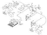
- FIG. 1is a diagram illustrating an embodiment of a networked access control system 100 that includes an embodiment of a power-over-ethernet (“POE”) controller 101 comprising an integrated Fire Access Control Panel (“FACP”) circuit.
- POE controllermay further comprise a FACP port having input terminals configured to couple the POE controller with the FACP of an automated fire detection system.
- FACPFire Access Control Panel
- An ethernet communications path 113connects the controller 101 with a remote host computer 104 , which is powered by an 110/220V AC input 112 .
- the host computer 104may be powered by a power source such as a battery, a fuel cell, etc.
- the ethernet communications path 113may include one or more pieces of ethernet cable and/or one or more switches, relays, routers, and/or other computer network devices.
- the ethernet communications path 113is used to convey data between at least the POE controller 101 and the remote host computer 104 , and is also used to convey electrical power to the POE controller 101 via the controller's ethernet port.
- the electrical power supplied over the ethernet communications path 113is provided by a POE source.
- the POE sourcemay be integrated within a network device (e.g., gateway, hub, host computer, etc.).
- an external POE sourcemay be coupled with a network device. Portions of or all of the electrical power received via the ethernet port of the POE controller 101 are distributed to one or more peripheral devices connected with the POE controller 101 .
- non-limiting examples of peripheral devicesinclude a door strike 103 and an access device 102 .
- the access device 102may be a peripheral device such as an access control reader, a biometric identification device, a keypad, and the like.
- the door strike 103may be an electric door strike, a magnetic door strike, or an electromagnetic door strike.
- a communications path 114connects the POE controller 101 with the door strike 103 . Electrical power (e.g., current/voltage) from one or more components of the POE controller 101 are routed over the communications path 114 to control operation of the door strike 103 (e.g. to latch/de-latch the door strike, which has the effect of locking/unlocking a door next to which the door strike is installed).
- the communications path 114may comprise a pair of shielded (or unshielded) wires. One wire is connected with a positive terminal of the door strike, and the other wire is connected with a negative terminal of the door strike. As denoted by the triangle containing the numeral “1”, a protection device should be connected across the door strike 103 .
- the protection deviceis a diode 131 having its cathode to the positive side of the door strike 103 .
- the access device 102may be an access control reader.
- the access control readermay comprise a keypad, a magnetic stripe reader, a RFID reader, a biometric scanner, a camera, a microphone, and/or a display.
- a communications path 115connects the access device 102 with the POE controller 101 . Electrical power (e.g., current/voltage) from one or more components of the POE controller 101 is routed over the communications path 115 to power the access device 102 . This electrical power may be derived from electrical power received via the POE controller's ethernet port (J 10 in FIG. 6 ).
- the communications path 115is also used to transmit data between the POE controller 101 and the access device 102 .
- the data transmitted over the communications path 115may include, but is not limited to, signals that cause one or more components of the POE controller 101 to generate and transmit electrical power over the communications path 114 to operate the door strike 103 .
- the communications path 115comprises a pair of shielded wires.
- the access device 102receives identification data from a user of the access control system 100 and relays this identification data to the controller 101 , which processes the identification data to determine the access privileges (if any) associated therewith. If appropriate access privileges exist, the controller 101 may operate to delatch the door strike 103 / 105 . If insufficient (or revoked) access privileges exist, the controller 101 may keep the door strike 103 / 105 securely latched.
- the POE controller 101is configured to be optionally connected with a Fire Alarm Control Panel (“FACP”) 129 via a FACP communication path 130 , which may comprise a pair of shielded wires.
- the FACP 129is configured to override the POE controller 101 and de-latch the door strike when the FACP is in an alarm condition.
- An alarm conditionmay be generated at least by operation of a fire detection sensor, a manual switch, and/or by operation of a fire alarm pull device.
- a jumpermay be connected across the POE controller's FACP connectors (J 6 —as shown in FIG. 6 ).
- the FACP 129is powered by its own local power supply (not shown).
- an embodiment of a controller 101may be powered by a local power supply or backup power supply (e.g., a battery, a solar cell, a fuel cell, and equivalents) (not shown).
- a door strike 105 powered by another local power supply 109may be coupled with the POE controller 101 .
- the local power supply 109may be powered via a 110/220V AC input 111 .
- a communications path 117 formed of two or more shielded wiresmay connect both the door strike 105 and the local power supply 109 with the POE controller 101 .
- a protection deviceshould be connected across the door strike 105 .
- the protection devicemay be a Metal Oxide Varistor (“MOV”) or a diode 132 .
- MOVMetal Oxide Varistor
- the fuse 133couples the local power supply 109 with the POE controller 101 and serves to protect the relay.
- the current restrictionshould be limited to less than about 2 amps to prevent damage to the relay in the POE controller 101 , but different embodiments may require different current restrictions (if any).
- the current limitingmay be achieved either by using a power supply 109 that has built in current limiting or by wiring in a fuse that is external to the power supply 109 .
- a separate local power supplymay be used to power the access device 102 .
- another communications path 116may couple the controller 101 with a relay 106 and further couple the relay 106 with an output device 107 and its local power supply 108 .
- the local power supply 108may receive electrical power via a 110/220V AC input 110 (and/or via a power source such as a battery, fuel cell, etc.).
- the communications path 116may comprise two or more shielded wires.
- a protection devicesuch as diode 134
- diode 134may be connected across the output device 107 (with the cathode of the diode 134 connected with a positive side of the output device 107 ).
- the current through the relay coil 106is limited to less than about 0.2 amps to prevent damage to the POE controller 101 .
- Non-limiting embodiments of an output device 107include a siren, a horn, a lamp, etc.
- a signal produced by the controller 101causes the output device 107 to produce a visual and/or audio indication of an alarm event.
- the POE controller 101is installed at a door for which access control is desired. Specifically, the POE controller 101 is installed above (or adjacent a side of) the door and on a side of the wall that is interior to the room/area to be protected. If the room/area to be protected includes an automated fire detection system, the POE controller 101 is connected with the automated fire detection system's FACP.
- Shielded wires forming the communications path 114are connected to the door strike 103 and to the POE controller 101 .
- a protection device 131is connected across the door strike 103 .
- the access device 102is installed next to the door on a side of a wall that is exterior to the room/area to be protected.
- Shielded wires forming the communications path 115are connected to the POE controller 101 and to the access device 102 .
- An ethernet cable, forming the ethernet communication path 113is then connected to the POE controller's ethernet port. In this (or equivalent) manner, one or more doors may be quickly and inexpensively equipped with an access control system.
- a circuitcoupled with the controller's ethernet port (J 10 in FIG. 6 ) is configured to transform all or part of the electrical power received via the ethernet port and to route the same to one or more components of the controller 101 and to at least one peripheral device ( 102 , 103 , 106 ) coupled with the controller 101 .
- Connecting an ethernet cable to the POE controller 101also allows data to be transmitted between the host computer 104 and the POE controller 101 .
- Data (if any) transmitted between the host computer 104 and the access device 102passes through the controller 101 .
- the POE controller 101may include a microprocessor (not shown) that is configured to program the POE controller 101 , to dynamically load one or more firmware programs and/or software programs to a memory of the POE controller 101 , and to program one or more peripheral devices when the one or more peripheral devices are coupled with the POE controller 101 .
- a memory (not shown) of the POE controller 101may contain a database of stored information that permits stand-alone operation of the POE controller 101 , the door strike 103 , and the access device 102 when data transfer between the POE controller 101 and a host computer 104 ceases. Additionally, the POE controller 101 may be further configured to transmit to the host computer 104 data indicative of at least one of: detected tampering of the controller housing, an AC power failure, and a low battery pack back-up condition.
- User identification codes and associated access privileges generated by the host computer 104 and/or stored in a memory thereofmay be transmitted (in real time or in near real-time) to the memory of the POE controller 101 .
- the POE controller 101may relay these codes and access privileges to the access device 102 .
- data indicating access records and/or operational status of the POE controller 101 and/or its peripheralsmay be stored in a memory of the POE controller 101 and/or transmitted via the ethernet communications path 113 to the host computer 104 .
- the POE controller 101compares the identification data provided by the user to a database of user identification data and associated access privileges.
- This database of user identification data and associated access privilegesmay be stored in the memory of the POE controller 101 and/or updated in real-time or near real-time by the host computer 104 .
- the door strike 103is operated to allow the user to open the door, and an access log entry is created.
- the access log (and its entries)is stored in the memory of the POE controller and may be transmitted to the host computer 104 via the ethernet communications path 113 . If no match is found (or if a match is found that has revoked access privileges), the door strike 103 is operated to prevent the door from being opened. An access log entry to record the denial of entry may be generated and stored (in the memory of the POE controller 101 ).
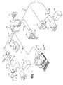
- FIG. 2is a diagram that illustrates a system 100 having an alternate network configuration for connecting an embodiment of the POE controller 101 of FIG. 1 with the remote host computer 104 , assuming the hub/jack 118 is a POE source. If the hub/jack 118 is not a POE source, the system 100 may be alternatively configured. Although omitted in FIG. 2 for simplicity and ease of illustration, the system 100 is understood to comprise at least the additional elements shown in FIG. 1 and described above.
- the ethernet communications path 113may comprise a hub/jack 118 , a gateway/router 119 , and a network 120 .
- the network 120may comprise a wide area network (“WAN”) such as the Internet and/or a local area network (“LAN”).
- WANwide area network
- LANlocal area network
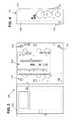
- FIG. 3is a front view of an embodiment of the POE controller 101 of FIG. 1 .
- the POE controller 101may include a tamper-proof enclosure (or housing) that comprises a base portion 121 and a hinged, latchable door 122 .
- the door 122is shown in an open position so that the interior of the enclosure's base portion 121 can be seen.
- the base portion 121includes a base plate and four sidewalls attached thereto.
- Mounting holes 123are provided in the base plate for securing the POE controller 101 to a wall or other substrate. Fasteners (not shown) are inserted through the mounting holes 123 to fasten the base portion 121 in place.
- a CPU printed circuit board (“PCB”) 200is mounted within the interior of the base portion 121 . Configuration and operation of the PCB 200 are described below with respect to FIG. 6 .
- FIG. 4is a side view of an embodiment of the tamper-proof enclosure of the POE controller 101 of FIG. 1 .
- the tamper-proof enclosureincludes a base portion 121 and a hinged door 122 .
- the door 122includes a latch mechanism 126 .
- a sidewall of the base portion 121includes one or more removable stamped cut-outs 125 . When these stamped cut-outs 125 are removed, shielded wires and/or ethernet cable may be introduced within the interior of the base portion 121 and connected to the PCB 200 .
- FIG. 5is a bottom view of an embodiment of tamper-proof enclosure of the POE controller 101 of FIG. 1 .
- FIG. 5illustrates the base portion 121 , the hinged door 122 , and the latch mechanism 126 previously shown and discussed. Additionally, FIG. 5 illustrates an earth ground connector 127 attached to the sidewall of the base portion 121 and one or more removable stamped cut-outs 128 .
- the earth ground connector 127is electrically connected to the PCB 200 .
- a ground wire(or wires) is connected at one end to the earth ground connector 127 and connected at the other end with ground.
- the stamped cut-outs 128may be removed and shielded wires and/or ethernet cable inserted into the interior of the base portion 121 and connected to the PCB 200 . Additionally, the shielding of the wires may be connected to the earth ground connector 127 .
- FIG. 6is a diagram of an embodiment of a CPU printed-circuit-board (“PCB”) 200 that comprises an embodiment of the POE controller 101 of FIG. 1 .
- the PCB 200comprises ports (also called jumpers and/or connectors) J 1 , J 2 , J 3 , J 4 , J 5 , J 6 , J 7 , J 8 , J 9 , J 10 , J 11 , J 12 , W 2 , W 3 , and W 5 .
- ports J 1 , J 2 , J 3 , and J 4comprise eight pins (numbered 1 , 2 , 3 , 4 , 5 , 6 , 7 , and 8 ).
- the port J 5comprises six pins (numbered 1 , 2 , 3 , 4 , 5 , and 6 ).
- the PCB 200further comprises switches SW 1 , SW 2 , and SW 3 as well as a bank of LEDs (listed in the order shown in the exemplary diagram of FIG. 6 ) D 85 , D 14 , D 15 , D 16 , D 17 , D 18 , D 19 , D 20 , D 21 , D 51 , D 52 , D 53 , D 54 , D 55 ,D 56 , D 57 , D 58 , D 24 , D 25 , D 26 , D 27 , and D 28 .
- the PCB 200further comprises ports P 1 , P 2 , P 3 , and P 4 for modem use. Each of these components is more fully described, below.
- Ports J 1 , J 2 , J 3 , J 4 , and J 5are used to connect one or more peripherals to the PCB 200 .
- an access devicesuch as a Wiegand-type access control reader
- Another Wiegand-type access devicemay also be connected to the port J 3 .
- another type of access devicesuch as a F/2F access control reader
- Other types of access devicesinclude a Strobed-type access control reader and a Supervised F/2F-type access control reader.
- a door alarm contact and exit request buttonmay be connected to pins 1 , 2 , 3 , and 4 of port J 2 (using Belden 8725 or equivalent).
- a second door alarm contact and exit request buttonmay be connected to pins 1 , 2 , 3 , and 4 of port J 4 (using Belden 8725 or equivalent).
- a door strike(powered using electrical power provided via the ethernet port J 10 ) may be connected to pins 6 , 7 , and 8 of port J 2 (using Belden 8725 or equivalent).
- a door strike(powered using a local power supply) may be connected to pins 6 , 7 , and 8 of port J 4 (using Belden 8725 or equivalent).
- a jumper wireshould be positioned on connector W 2 and/or connector W 3 to select either 12 VDC or 24 VDC strike power. Pins 1 and 2 may be used for 12 VDC and pins 2 and 3 may be used for 24 VDC.
- no jumpershould be used.
- the shield groundsmust be stripped back through the stamped cut-outs and grounded to the earth ground connector.
- Port J 5is a pluggable screw terminal block.
- Port J 6is used to connect the PCB 200 to a Fire Alarm Control Panel (“FACP”) of an automated fire system. If a FACP is not used, the jumper 204 shown on the J 6 FACP input should remain in place for correct operation of the POE controller ( 101 in FIG. 1 ).
- FACPFire Alarm Control Panel
- Port J 7is a pluggable screw terminal block.
- Port J 8is a pluggable screw terminal block that may be used to connect a 24 VDC, 1 amp auxiliary power supply to the PCB 200 .
- Port J 9is a nine-pin female D-sub-receptacle, which controls a console port.
- Port J 10is an RJ45 Standard Cat 5 ethernet jack, which controls a RJ45 ethernet network connection.
- one end of an ethernet cable 113may be looped through ferrite 202 before removably connecting to the port J 10 .
- the other end of the ethernet cable 113is coupled with a host computer or a network connection (e.g., a gateway, a router, etc.) that has an integrated POE source or is coupled with an external POE source.
- Port J 11is a RJ11 standard telephone jack.
- Port J 12is an insertion jack for a microprocessor.
- W 5is a two-pin jumper that provides tamper inputs that permit the housing of the POE controller be protected against and/or monitored for unauthorized tampering.
- P 1 , P 2 , P 3 , and P 4are connectors used by a modem.
- the connectors P 1 , P 2 , P 3 , and P 4(and other circuit elements) are covered by a substrate of the PCB 200 .
- SW 1 , SW 2 and SW 3are sets of DIP switches used for configuring the PCB 200 to operate with various types of peripheral devices such as, but not limited to Magstripe readers and Wiegand readers.
- SW 1includes eight DIP switches;
- SW 2includes four DIP switches, and
- SW 3includes four DIP switches.
- DIP switches 1 and 2 of SW 1are set to “ON”.
- DIP switches 1 and 4 of SW 1are set to “ON.”
- Other SW 1 DIP switch combinationsmay be used to connect other types of readers and/or other kinds of peripheral devices.
- the DIP switch 4 of SW 2is set to “OFF”.
- the DIP switches 1 , 2 , 3 , 4 of SW 3are turned on or off depending on the type of communication protocol used to make the connection. For 120 ohms transmit pair termination, DIP switch 1 of SW 3 is “ON”. For no transmit pair termination (default), DIP switch 1 of SW 3 is “OFF”. For 120 ohms receive pair termination, DIP switch 2 of SW 3 is “ON”. For no receive pair termination, DIP switch 2 of SW 3 is “OFF”. For RS485-4 wire (default), DIP switches 3 and 4 of SW 3 are “ON”. For RS485-2 wire, DIP switches 3 and 4 of SW 3 are “OFF”.
- SW 4is a manual switch used to place an embodiment of the POE controller in BOOT MODE, which enables use of an Integrated Configuration Tool. In an embodiment, pressing and holding SW 4 for up to about 5 seconds will turn LED D 19 “ON”. Once the LED D 19 is illuminated, the switch S 4 is released. Thereafter, the LED D 19 turns “OFF” once the Integrated Configuration Tool has been enabled.
- SW 5is a manual switch used for HARDWARE RESET that restarts (resets) the PCB 200 .
- the switch SW 5should only be utilized when performing a controlled manual shutdown of the application as indicated below or if instructed to do so by customer support and/or a technician.
- both the switch SW 5 and the switch SW 6should be used. First, press the switch SW 6 to stop an application being run on the PCB 200 . Then press and release the switch S 5 to restart (reset) the PCB 200 .
- SW 6is a manual switch used for SHUTDOWN REQUEST that stops an application running on the PCB 200 and puts the PCB 200 into a maintenance mode, which allows the PCB 200 to be removed. Since the PCB 200 runs an operating system just like a computer, it must be shut down correctly. Pressing SW 6 shuts down the operating system/application of the PCB 200 , and is like using the “Shut down” feature of a computer. To properly restart the PCB 200 , both the switch SW 5 and the switch SW 6 should be used. First, press the switch SW 6 to stop an application being run on the PCB 200 . Then press and release the switch S 5 to restart (reset) the PCB 200 .
- SW 7is a manual switch used for RESTORE DEFAULTS that returns the configuration of the PCB 200 to the factory defaults. Specifically, pressing the switch SW 7 for about five seconds restores the factory defaults for PRIMARY CONNECTION (ETHERNET), IP ADDRESS (192.168.6.6), MASK (255.255.255.0), and GATEWAY (192.168.6.1).
- ETHERNETPRIMARY CONNECTION
- IP ADDRESS(192.168.6.6
- MASK255.255.255.0
- GATEWAY(192.168.6.1
- the PCB 200provides network and dial-up (fallback) capabilities in one board.
- these capabilitiesinclude: support for ethernet networks; support for network protocols (e.g., DHCP, TCP/IP, UDP, and DNS); support for optional, integrated modem board for fallback dial-up connectivity; provision of nonvolatile storage (referred to as persistent mode of operation), which affords a faster reset recovery and allows for host-less operation of the POE controller; utilization of 32-bit platform, which provides fast response times and high capacity throughput; support for remote diagnostics; provision of a browser-based configuration tool; and provision of a tunable, offline, history buffer.
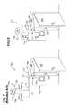
- FIG. 8is a diagram of an embodiment of the access control system 100 of FIG. 1 , with some of the components shown in FIG. 1 omitted for simplicity and ease of description.
- the access control system 100comprises a POE controller 101 , an access control reader 102 , and a door strike 103 (which is installed in a jamb of a door 802 ).
- the door strike 103 and the access control reader 102are each powered via electrical power supplied via an ethernet port of the POE controller 101 . Consequently, if FIG. 8 is compared with FIG. 7 (Related Art), it is seen that embodiments of the new access control system 100 eliminate at least the junction box 705 , the external power supply 702 , and the external power supply 703 .
- some advantages afforded by embodiments of the access control system 100 over the prior access control systems 700include, but are not limited to: less equipment, fewer terminations, less wiring (since the access control system 100 is ethernet (CAT-5) based), edge of network devices, full intelligence, and electrical power provided via an ethernet connection.
- CAT-5ethernet
- a communications path 114couples the POE controller 101 with the door strike 103 .
- a communications path 115couples the POE controller 101 with the access control reader 102 .
- a communications path 130couples the POE controller 101 with a FACP 129 .
- a communications path 116couples the POE controller 101 with a door sensor 717 .
- the POE controller 101may be coupled with a network 120 , a remote POE source (not shown), and a remote host computer 104 via an ethernet communications path 113 .
- the POE controller 101may also be coupled with an exit device 801 via a communications path 803 .
- kits for providing secured access to a doormay include at least a controller 101 having an ethernet port J 10 , wherein the controller 101 is configured to operate using electrical power supplied via the ethernet port J 10 , and wherein the controller 101 is further configured to control an access device 102 and a door strike 103 (and/or 105 ).
- the controller 101may further comprise a Fire Alarm Control Panel (FACP) circuit (not shown) and/or connector J 6 for coupling the controller 101 with a FACP 129 .
- FACPFire Alarm Control Panel
- the controller's integrated FACP circuitis configured to override the controller 101 and de-latch the door strike 103 (and/or 105 ) when the Fire Alarm Control Panel 129 is in an alarm condition.
- the kitmay further include a door strike 103 (and/or 105 ) that is configured to operate using a portion of the electrical power supplied to the controller 101 via the controller's ethernet port J 10 .
- the kitmay further include an access device 102 configured to operate using a portion of the electrical power supplied via the controller's ethernet port J 10 .
- the kitmay further include a door sensor 717 and/or an output device 107 (and/or its relay 106 )
Landscapes
- Physics & Mathematics (AREA)
- General Physics & Mathematics (AREA)
- Business, Economics & Management (AREA)
- Emergency Management (AREA)
- Alarm Systems (AREA)
Abstract
Description
Claims (22)
Priority Applications (4)
| Application Number | Priority Date | Filing Date | Title |
|---|---|---|---|
| US11/684,179US8207814B2 (en) | 2007-03-09 | 2007-03-09 | Kit and system for providing security access to a door using power over ethernet with data persistence and fire alarm control panel integration |
| CA002679438ACA2679438A1 (en) | 2007-03-09 | 2008-02-19 | Kit and system for providing security access to a door using power over ethernet with data persistence and fire alarm control panel integration |
| PCT/US2008/054233WO2008112389A1 (en) | 2007-03-09 | 2008-02-19 | Kit and system for providing security access to a door using power over ethernet with data persistence and fire alarm control panel integration |
| EP08730104AEP2122583A1 (en) | 2007-03-09 | 2008-02-19 | Kit and system for providing security access to a door using power over ethernet with data persistence and fire alarm control panel integration |
Applications Claiming Priority (1)
| Application Number | Priority Date | Filing Date | Title |
|---|---|---|---|
| US11/684,179US8207814B2 (en) | 2007-03-09 | 2007-03-09 | Kit and system for providing security access to a door using power over ethernet with data persistence and fire alarm control panel integration |
Publications (2)
| Publication Number | Publication Date |
|---|---|
| US20080218330A1 US20080218330A1 (en) | 2008-09-11 |
| US8207814B2true US8207814B2 (en) | 2012-06-26 |
Family
ID=39493120
Family Applications (1)
| Application Number | Title | Priority Date | Filing Date |
|---|---|---|---|
| US11/684,179Active2029-05-04US8207814B2 (en) | 2007-03-09 | 2007-03-09 | Kit and system for providing security access to a door using power over ethernet with data persistence and fire alarm control panel integration |
Country Status (4)
| Country | Link |
|---|---|
| US (1) | US8207814B2 (en) |
| EP (1) | EP2122583A1 (en) |
| CA (1) | CA2679438A1 (en) |
| WO (1) | WO2008112389A1 (en) |
Cited By (2)
| Publication number | Priority date | Publication date | Assignee | Title |
|---|---|---|---|---|
| US9851982B2 (en)* | 2014-02-28 | 2017-12-26 | Tyco Fire & Security Gmbh | Emergency video camera system |
| US11747430B2 (en) | 2014-02-28 | 2023-09-05 | Tyco Fire & Security Gmbh | Correlation of sensory inputs to identify unauthorized persons |
Families Citing this family (25)
| Publication number | Priority date | Publication date | Assignee | Title |
|---|---|---|---|---|
| US8237570B1 (en)* | 2007-06-13 | 2012-08-07 | Essen Energy Conversion Devices Pvt. Ltd. | Integrated, high efficiency RFID UHF reader/antenna |
| US20090212920A1 (en)* | 2008-02-22 | 2009-08-27 | Xiao Hui Yang | Intelligent asset protection system |
| US8731689B2 (en) | 2008-05-06 | 2014-05-20 | Abl Ip Holding, Llc | Networked, wireless lighting control system with distributed intelligence |
| GB2476067A (en)* | 2009-12-09 | 2011-06-15 | Core Systems | Lock controller having different control outputs for different lock types |
| FR2955680B1 (en)* | 2010-01-26 | 2012-04-27 | Cegelec S A S | AUTOMATE OF ACCESS CONTROL MANAGEMENT |
| US8836470B2 (en)* | 2010-12-02 | 2014-09-16 | Viscount Security Systems Inc. | System and method for interfacing facility access with control |
| US20130305353A1 (en)* | 2012-05-10 | 2013-11-14 | Rutherford Controls International Corp. | Low Power Driver System and Method for Controlling The Same |
| US9319101B2 (en) | 2012-09-28 | 2016-04-19 | Siemens Industry, Inc. | System and method for ground fault detection in a transformer isolated communication channel of a network device |
| US9013980B2 (en)* | 2012-09-28 | 2015-04-21 | Siemens Industry, Inc. | System and method for fail-safe communication across a compromised communication channel of a network device |
| US9245398B2 (en)* | 2012-10-26 | 2016-01-26 | Eric George Plummer | Interactive door system to provide door access to a user |
| US9557719B2 (en)* | 2013-02-26 | 2017-01-31 | Honeywell International Inc. | Access control system using smart phone |
| US9397842B2 (en)* | 2014-10-15 | 2016-07-19 | Altronix Corporation | System and method for controlling an electrically actuated device |
| EP3394956B1 (en)* | 2015-12-21 | 2019-08-28 | Signify Holding B.V. | Power-over-ethernet lighting system |
| US10435916B2 (en)* | 2016-08-26 | 2019-10-08 | Dormakaba Usa Inc. | Locking system for a door |
| US10968669B2 (en) | 2017-08-30 | 2021-04-06 | Sensormatic Electronics, LLC | System and method for inductive power transfer to door |
| US10943415B2 (en) | 2017-08-30 | 2021-03-09 | Sensormatic Electronics, LLC | System and method for providing communication over inductive power transfer to door |
| US10937262B2 (en)* | 2017-08-30 | 2021-03-02 | Sensormatic Electronics, LLC | Door system with power management system and method of operation thereof |
| US11687048B2 (en) | 2017-09-18 | 2023-06-27 | Johnson Controls Tyco IP Holdings LLP | Method and apparatus for evaluation of temperature sensors |
| US10735418B2 (en)* | 2017-09-18 | 2020-08-04 | Johnson Controls Fire Protection LP | Method and system for service verification using access control system |
| US10681667B2 (en) | 2017-09-18 | 2020-06-09 | Johnson Controls Fire Protection LP | Method and system for service verification using WiFi signal strength mapping |
| US10755555B2 (en) | 2017-09-18 | 2020-08-25 | Johnson Controls Fire Protection LP | Method and apparatus for verifying service of installed devices using RFID |
| WO2019060834A1 (en)* | 2017-09-22 | 2019-03-28 | Schlage Lock Company Llc | Peripheral controller in an access control system |
| CA3098711C (en)* | 2018-03-23 | 2024-06-11 | Schlage Lock Company Llc | Power and communication arrangements for an access control system |
| EP3779899A1 (en)* | 2019-08-16 | 2021-02-17 | EUCHNER GmbH + Co. KG | Control device |
| CN110517382A (en)* | 2019-08-19 | 2019-11-29 | 深圳坚朗海贝斯智能科技有限公司 | Intelligent door lock system |
Citations (69)
| Publication number | Priority date | Publication date | Assignee | Title |
|---|---|---|---|---|
| US4455510A (en) | 1982-05-20 | 1984-06-19 | Hid Systems, Inc. | High intensity discharge ballast with hot restrike performance |
| US4574223A (en) | 1984-01-12 | 1986-03-04 | Hid Systems, Inc. | Fast warmup ballast for HID lamps |
| US4996525A (en)* | 1989-11-24 | 1991-02-26 | The United States Of America As Represented By The Secretary Of The Navy | R. F. lockout circuit for electronic locking system |
| US5070442A (en)* | 1989-12-14 | 1991-12-03 | Syron Townson Ann T | Computerized door locking and monitoring system using power-line carrier components |
| US5381136A (en)* | 1993-03-19 | 1995-01-10 | Northern Illinois Gas Company | Remote data collection and monitoring system for distribution line |
| US5764138A (en) | 1994-04-29 | 1998-06-09 | Hid Corporation | RF identification system for providing static data and one bit of variable data representative of an external stimulus |
| US5832090A (en) | 1995-08-10 | 1998-11-03 | Hid Corporation | Radio frequency transponder stored value system employing a secure encryption protocol |
| US5864580A (en) | 1996-08-26 | 1999-01-26 | Hid Corporation | Miniature wireless modem |
| US5898241A (en) | 1997-12-05 | 1999-04-27 | Hid Corporation | Read head for Wiegand token |
| US5908103A (en) | 1997-12-05 | 1999-06-01 | Hid Corporation | Token with Wiegand wire |
| US5936529A (en)* | 1997-07-24 | 1999-08-10 | Elmo-Tech Ltd. | Electronic monitoring system |
| US5955946A (en)* | 1998-02-06 | 1999-09-21 | Beheshti; Ali | Alarm/facility management unit |
| US6129963A (en) | 1996-09-09 | 2000-10-10 | Hid Systems, Inc. | Easy laminated sign manufacture |
| US6229300B1 (en) | 1998-12-03 | 2001-05-08 | Hid Corporation | Wiegand tilt sensor |
| US20020133655A1 (en)* | 2001-03-16 | 2002-09-19 | Ohad Falik | Sharing of functions between an embedded controller and a host processor |
| US6476708B1 (en) | 1998-03-20 | 2002-11-05 | Hid Corporation | Detection of an RFID device by an RF reader unit operating in a reduced power state |
| US6566997B1 (en) | 1999-12-03 | 2003-05-20 | Hid Corporation | Interference control method for RFID systems |
| US6577185B1 (en) | 2001-03-19 | 2003-06-10 | Cisco Systems Wireless Networking (Australia) Pty. Limited | Multi-stage operational amplifier for interstage amplification in a pipeline analog-to-digital converter |
| US6580696B1 (en) | 1999-03-15 | 2003-06-17 | Cisco Systems, Inc. | Multi-adaptation for a voice packet based |
| US6583720B1 (en)* | 1999-02-22 | 2003-06-24 | Early Warning Corporation | Command console for home monitoring system |
| US6598183B1 (en) | 2000-01-04 | 2003-07-22 | Cisco Systems, Inc. | Software tool for automated diagnosis and resolution of problems of voice, data and VoIP communications networks |
| US6597783B1 (en) | 2000-02-01 | 2003-07-22 | Cisco Systems, Inc. | System and method for storing, routing, and tracking digital documents in a call center |
| US6606681B1 (en) | 2001-02-23 | 2003-08-12 | Cisco Systems, Inc. | Optimized content addressable memory (CAM) |
| US6611624B1 (en) | 1998-03-13 | 2003-08-26 | Cisco Systems, Inc. | System and method for frame accurate splicing of compressed bitstreams |
| US6639703B1 (en) | 1999-03-18 | 2003-10-28 | Cisco Systems (Sweden) Aktiebolag | Receiver transponder for protected networks |
| US6650227B1 (en) | 1999-12-08 | 2003-11-18 | Hid Corporation | Reader for a radio frequency identification system having automatic tuning capability |
| US6684005B1 (en) | 1999-09-27 | 2004-01-27 | Cisco Systems (Sweden) Aktiebolag | Connection of an add/drop node |
| US6686804B1 (en) | 2001-03-19 | 2004-02-03 | Cisco Systems Wireless Networking (Australia) Pty. Limited | Frequency synthesizer using a VCO having a controllable operating point, and calibration and tuning thereof |
| US6704883B1 (en) | 1999-12-22 | 2004-03-09 | Cisco Systems, Inc. | Event-enabled distributed testing system |
| US6720861B1 (en)* | 1999-03-12 | 2004-04-13 | Best Access Systems | Wireless security control system |
| US6792457B1 (en) | 1998-10-13 | 2004-09-14 | Cisco Systems, Inc. | Multiple-level internet protocol accounting |
| US6807638B1 (en) | 2000-12-29 | 2004-10-19 | Cisco Systems O.I.A. (1988) Ltd. | Apparatus for and method of in-band clock compensation |
| US6832279B1 (en) | 2001-05-17 | 2004-12-14 | Cisco Systems, Inc. | Apparatus and technique for maintaining order among requests directed to a same address on an external bus of an intermediate network node |
| US6831898B1 (en) | 2000-08-16 | 2004-12-14 | Cisco Systems, Inc. | Multiple packet paths to improve reliability in an IP network |
| US6834058B1 (en) | 2000-12-29 | 2004-12-21 | Cisco Systems O.I.A. (1988) Ltd. | Synchronization and alignment of multiple variable length cell streams |
| US6845467B1 (en) | 2001-02-13 | 2005-01-18 | Cisco Systems Canada Co. | System and method of operation of dual redundant controllers |
| US6883012B1 (en) | 2001-03-19 | 2005-04-19 | Cisco Systems Wireless Networking (Australia) Pty Limited | Linear-to-log converter for power estimation in a wireless data network receiver |
| US20050085212A1 (en)* | 2003-10-16 | 2005-04-21 | Arkadiy Peker | High power architecture for power over Ethernet |
| US6888801B1 (en) | 2000-10-27 | 2005-05-03 | Cisco Systems, Inc. | Devices, software and methods for determining a quality of service for a VoIP connection |
| US6888413B1 (en) | 2001-03-19 | 2005-05-03 | Cisco Systems Wireless Networking (Australia) Pty Limited | Frequency synthesizer using a VCO having a controllable operating point, and calibration and tuning thereof |
| US6931101B1 (en) | 2000-05-26 | 2005-08-16 | Cisco Systems, Inc. | Method and apparatus for inband testing of an echo canceller |
| US6948044B1 (en) | 2002-07-30 | 2005-09-20 | Cisco Systems, Inc. | Methods and apparatus for storage virtualization |
| US6957358B1 (en) | 2002-01-28 | 2005-10-18 | Cisco Systems, Inc. | Scaling dynamic clock distribution for large service provider networks |
| US20050231349A1 (en)* | 2004-03-30 | 2005-10-20 | Honeywell International Inc. | Evacuation systems providing enhanced operational control |
| US6959044B1 (en) | 2001-08-21 | 2005-10-25 | Cisco Systems Canada Co. | Dynamic GOP system and method for digital video encoding |
| US6968092B1 (en) | 2001-08-21 | 2005-11-22 | Cisco Systems Canada Co. | System and method for reduced codebook vector quantization |
| US7003062B1 (en) | 2001-02-14 | 2006-02-21 | Cisco Systems Canada Co. | Method and system for distribution of clock and frame synchronization information |
| US7012901B2 (en) | 2001-02-28 | 2006-03-14 | Cisco Systems, Inc. | Devices, software and methods for generating aggregate comfort noise in teleconferencing over VoIP networks |
| US7035262B1 (en) | 2001-12-19 | 2006-04-25 | Cisco Systems, Inc. | Software-based emulation of single SONET path layer |
| US7039716B1 (en) | 2000-10-30 | 2006-05-02 | Cisco Systems, Inc. | Devices, software and methods for encoding abbreviated voice data for redundant transmission through VoIP network |
| US7085918B2 (en) | 2003-01-09 | 2006-08-01 | Cisco Systems, Inc. | Methods and apparatuses for evaluation of regular expressions of arbitrary size |
| WO2006084271A2 (en) | 2005-02-04 | 2006-08-10 | Jr Edmonds H Chandler | Method and apparatus for a merged power-communication cable in door security environment |
| US7099287B1 (en) | 2001-03-06 | 2006-08-29 | Cisco Systems O.I.A. (1988) Ltd. | Node detection and ring configuration for physical star connected networks |
| US7113584B2 (en)* | 2001-03-26 | 2006-09-26 | Seay John G | Digital communication translator |
| US20060250271A1 (en)* | 2005-04-21 | 2006-11-09 | Simplexgrinnell Lp | Muster station and system for emergency communication |
| US7136709B2 (en)* | 2003-11-04 | 2006-11-14 | Universal Electronics Inc. | Home appliance control system and methods in a networked environment |
| US7154381B2 (en)* | 2003-05-23 | 2006-12-26 | Sonos, Inc. | System and method for operating a sensed power device over data wiring |
| US20070008068A1 (en)* | 2005-06-28 | 2007-01-11 | Media Cart Holdings, Inc. | Media enabled advertising shopping cart system |
| US20070019560A1 (en) | 2005-07-19 | 2007-01-25 | Rosemount Inc. | Interface module with power over ethernet function |
| US20070075586A1 (en)* | 2005-10-05 | 2007-04-05 | Bogue Edward M | Ethernet powered device with an internaly controlled auxiliary power ouput |
| US7218217B2 (en)* | 2004-08-05 | 2007-05-15 | Honeywell International, Inc. | False alarm reduction in security systems using weather sensor and control panel logic |
| US20070241879A1 (en)* | 2006-04-13 | 2007-10-18 | Jobe Michael L | Communications for Automated Building Protection Systems |
| US7333010B2 (en)* | 2005-03-25 | 2008-02-19 | Simplexgrinnell Lp | Method and apparatus for verifying operation of notification appliances during low input voltage condition |
| US7369037B2 (en)* | 2003-12-11 | 2008-05-06 | Simplexgrinnell Lp | Programmable multicandela notification device |
| US7391319B1 (en)* | 2005-08-22 | 2008-06-24 | Walker Ethan A | Wireless fire alarm door unlocking interface |
| US20080204220A1 (en)* | 2007-02-28 | 2008-08-28 | Leemon Claude Baird | Power over data cable system and method |
| US7461174B2 (en)* | 2003-10-03 | 2008-12-02 | Asoka Usa Corporation | Method and system for virtual powerline local area networks |
| US7583188B2 (en)* | 2004-08-31 | 2009-09-01 | Ingersoll-Rand Company | Software controlled access control door controller |
| US7734572B2 (en)* | 2006-04-04 | 2010-06-08 | Panduit Corp. | Building automation system controller |
Family Cites Families (10)
| Publication number | Priority date | Publication date | Assignee | Title |
|---|---|---|---|---|
| US6191687B1 (en)* | 1998-09-24 | 2001-02-20 | Hid Corporation | Wiegand effect energy generator |
| US6729929B1 (en)* | 1999-03-17 | 2004-05-04 | Cisco Systems, Inc. | Method and apparatus for controlling wireless networks |
| US6950213B1 (en)* | 2000-12-20 | 2005-09-27 | Cisco Systems, Inc. | Fast method for fax encoded data conversion |
| US6665339B1 (en)* | 2001-03-19 | 2003-12-16 | Cisco Systems Wireless Networking (Australia) Pty. Limited | Method and apparatus for reducing oscillator pull in a CMOS wireless transceiver integrated circuit |
| US7065036B1 (en)* | 2001-03-19 | 2006-06-20 | Cisco Systems Wireless Networking (Australia) Pty Limited | Method and apparatus to reduce latency in a data network wireless radio receiver |
| US6944121B1 (en)* | 2001-03-19 | 2005-09-13 | Cisco Systems Wireless Networking (Australia) Pty Limited | Wireless computer network including a mobile appliance containing a single chip transceiver |
| US7046746B1 (en)* | 2001-03-19 | 2006-05-16 | Cisco Systems Wireless Networking (Australia) Pty Limited | Adaptive Viterbi decoder for a wireless data network receiver |
| US7058071B1 (en)* | 2002-03-04 | 2006-06-06 | Cisco Systems Wireless Networking (Australia) Pty Limited | Method and apparatus using pipelined execution data sets for processing transmission frame sequences conforming to a wireless network MAC protocol |
| US6898198B1 (en)* | 2003-02-14 | 2005-05-24 | Cisco Systems Wireless Networking (Australia) Pty Limited | Selecting the data rate of a wireless network link according to a measure of error vector magnitude |
| US7003274B1 (en)* | 2003-03-05 | 2006-02-21 | Cisco Systems Wireless Networking (Australia) Pty Limited | Frequency synthesizer and synthesis method for generating a multiband local oscillator signal |
- 2007
- 2007-03-09USUS11/684,179patent/US8207814B2/enactiveActive
- 2008
- 2008-02-19EPEP08730104Apatent/EP2122583A1/ennot_activeWithdrawn
- 2008-02-19WOPCT/US2008/054233patent/WO2008112389A1/enactiveApplication Filing
- 2008-02-19CACA002679438Apatent/CA2679438A1/ennot_activeAbandoned
Patent Citations (70)
| Publication number | Priority date | Publication date | Assignee | Title |
|---|---|---|---|---|
| US4455510A (en) | 1982-05-20 | 1984-06-19 | Hid Systems, Inc. | High intensity discharge ballast with hot restrike performance |
| US4574223A (en) | 1984-01-12 | 1986-03-04 | Hid Systems, Inc. | Fast warmup ballast for HID lamps |
| US4996525A (en)* | 1989-11-24 | 1991-02-26 | The United States Of America As Represented By The Secretary Of The Navy | R. F. lockout circuit for electronic locking system |
| US5070442A (en)* | 1989-12-14 | 1991-12-03 | Syron Townson Ann T | Computerized door locking and monitoring system using power-line carrier components |
| US5381136A (en)* | 1993-03-19 | 1995-01-10 | Northern Illinois Gas Company | Remote data collection and monitoring system for distribution line |
| US5764138A (en) | 1994-04-29 | 1998-06-09 | Hid Corporation | RF identification system for providing static data and one bit of variable data representative of an external stimulus |
| US5832090A (en) | 1995-08-10 | 1998-11-03 | Hid Corporation | Radio frequency transponder stored value system employing a secure encryption protocol |
| US5864580A (en) | 1996-08-26 | 1999-01-26 | Hid Corporation | Miniature wireless modem |
| US6129963A (en) | 1996-09-09 | 2000-10-10 | Hid Systems, Inc. | Easy laminated sign manufacture |
| US5936529A (en)* | 1997-07-24 | 1999-08-10 | Elmo-Tech Ltd. | Electronic monitoring system |
| US5898241A (en) | 1997-12-05 | 1999-04-27 | Hid Corporation | Read head for Wiegand token |
| US5908103A (en) | 1997-12-05 | 1999-06-01 | Hid Corporation | Token with Wiegand wire |
| US5955946A (en)* | 1998-02-06 | 1999-09-21 | Beheshti; Ali | Alarm/facility management unit |
| US6611624B1 (en) | 1998-03-13 | 2003-08-26 | Cisco Systems, Inc. | System and method for frame accurate splicing of compressed bitstreams |
| US6476708B1 (en) | 1998-03-20 | 2002-11-05 | Hid Corporation | Detection of an RFID device by an RF reader unit operating in a reduced power state |
| US6792457B1 (en) | 1998-10-13 | 2004-09-14 | Cisco Systems, Inc. | Multiple-level internet protocol accounting |
| US6229300B1 (en) | 1998-12-03 | 2001-05-08 | Hid Corporation | Wiegand tilt sensor |
| US6583720B1 (en)* | 1999-02-22 | 2003-06-24 | Early Warning Corporation | Command console for home monitoring system |
| US6720861B1 (en)* | 1999-03-12 | 2004-04-13 | Best Access Systems | Wireless security control system |
| US6580696B1 (en) | 1999-03-15 | 2003-06-17 | Cisco Systems, Inc. | Multi-adaptation for a voice packet based |
| US6639703B1 (en) | 1999-03-18 | 2003-10-28 | Cisco Systems (Sweden) Aktiebolag | Receiver transponder for protected networks |
| US6684005B1 (en) | 1999-09-27 | 2004-01-27 | Cisco Systems (Sweden) Aktiebolag | Connection of an add/drop node |
| US6566997B1 (en) | 1999-12-03 | 2003-05-20 | Hid Corporation | Interference control method for RFID systems |
| US6650227B1 (en) | 1999-12-08 | 2003-11-18 | Hid Corporation | Reader for a radio frequency identification system having automatic tuning capability |
| US6704883B1 (en) | 1999-12-22 | 2004-03-09 | Cisco Systems, Inc. | Event-enabled distributed testing system |
| US6598183B1 (en) | 2000-01-04 | 2003-07-22 | Cisco Systems, Inc. | Software tool for automated diagnosis and resolution of problems of voice, data and VoIP communications networks |
| US6597783B1 (en) | 2000-02-01 | 2003-07-22 | Cisco Systems, Inc. | System and method for storing, routing, and tracking digital documents in a call center |
| US6931101B1 (en) | 2000-05-26 | 2005-08-16 | Cisco Systems, Inc. | Method and apparatus for inband testing of an echo canceller |
| US6831898B1 (en) | 2000-08-16 | 2004-12-14 | Cisco Systems, Inc. | Multiple packet paths to improve reliability in an IP network |
| US6888801B1 (en) | 2000-10-27 | 2005-05-03 | Cisco Systems, Inc. | Devices, software and methods for determining a quality of service for a VoIP connection |
| US7039716B1 (en) | 2000-10-30 | 2006-05-02 | Cisco Systems, Inc. | Devices, software and methods for encoding abbreviated voice data for redundant transmission through VoIP network |
| US6834058B1 (en) | 2000-12-29 | 2004-12-21 | Cisco Systems O.I.A. (1988) Ltd. | Synchronization and alignment of multiple variable length cell streams |
| US6807638B1 (en) | 2000-12-29 | 2004-10-19 | Cisco Systems O.I.A. (1988) Ltd. | Apparatus for and method of in-band clock compensation |
| US6845467B1 (en) | 2001-02-13 | 2005-01-18 | Cisco Systems Canada Co. | System and method of operation of dual redundant controllers |
| US7003062B1 (en) | 2001-02-14 | 2006-02-21 | Cisco Systems Canada Co. | Method and system for distribution of clock and frame synchronization information |
| US6606681B1 (en) | 2001-02-23 | 2003-08-12 | Cisco Systems, Inc. | Optimized content addressable memory (CAM) |
| US7012901B2 (en) | 2001-02-28 | 2006-03-14 | Cisco Systems, Inc. | Devices, software and methods for generating aggregate comfort noise in teleconferencing over VoIP networks |
| US7099287B1 (en) | 2001-03-06 | 2006-08-29 | Cisco Systems O.I.A. (1988) Ltd. | Node detection and ring configuration for physical star connected networks |
| US20020133655A1 (en)* | 2001-03-16 | 2002-09-19 | Ohad Falik | Sharing of functions between an embedded controller and a host processor |
| US6577185B1 (en) | 2001-03-19 | 2003-06-10 | Cisco Systems Wireless Networking (Australia) Pty. Limited | Multi-stage operational amplifier for interstage amplification in a pipeline analog-to-digital converter |
| US6888413B1 (en) | 2001-03-19 | 2005-05-03 | Cisco Systems Wireless Networking (Australia) Pty Limited | Frequency synthesizer using a VCO having a controllable operating point, and calibration and tuning thereof |
| US6883012B1 (en) | 2001-03-19 | 2005-04-19 | Cisco Systems Wireless Networking (Australia) Pty Limited | Linear-to-log converter for power estimation in a wireless data network receiver |
| US6686804B1 (en) | 2001-03-19 | 2004-02-03 | Cisco Systems Wireless Networking (Australia) Pty. Limited | Frequency synthesizer using a VCO having a controllable operating point, and calibration and tuning thereof |
| US7113584B2 (en)* | 2001-03-26 | 2006-09-26 | Seay John G | Digital communication translator |
| US6832279B1 (en) | 2001-05-17 | 2004-12-14 | Cisco Systems, Inc. | Apparatus and technique for maintaining order among requests directed to a same address on an external bus of an intermediate network node |
| US6959044B1 (en) | 2001-08-21 | 2005-10-25 | Cisco Systems Canada Co. | Dynamic GOP system and method for digital video encoding |
| US6968092B1 (en) | 2001-08-21 | 2005-11-22 | Cisco Systems Canada Co. | System and method for reduced codebook vector quantization |
| US7035262B1 (en) | 2001-12-19 | 2006-04-25 | Cisco Systems, Inc. | Software-based emulation of single SONET path layer |
| US6957358B1 (en) | 2002-01-28 | 2005-10-18 | Cisco Systems, Inc. | Scaling dynamic clock distribution for large service provider networks |
| US6948044B1 (en) | 2002-07-30 | 2005-09-20 | Cisco Systems, Inc. | Methods and apparatus for storage virtualization |
| US7085918B2 (en) | 2003-01-09 | 2006-08-01 | Cisco Systems, Inc. | Methods and apparatuses for evaluation of regular expressions of arbitrary size |
| US7154381B2 (en)* | 2003-05-23 | 2006-12-26 | Sonos, Inc. | System and method for operating a sensed power device over data wiring |
| US7461174B2 (en)* | 2003-10-03 | 2008-12-02 | Asoka Usa Corporation | Method and system for virtual powerline local area networks |
| US20050085212A1 (en)* | 2003-10-16 | 2005-04-21 | Arkadiy Peker | High power architecture for power over Ethernet |
| US7136709B2 (en)* | 2003-11-04 | 2006-11-14 | Universal Electronics Inc. | Home appliance control system and methods in a networked environment |
| US7369037B2 (en)* | 2003-12-11 | 2008-05-06 | Simplexgrinnell Lp | Programmable multicandela notification device |
| US20050231349A1 (en)* | 2004-03-30 | 2005-10-20 | Honeywell International Inc. | Evacuation systems providing enhanced operational control |
| US7148810B2 (en)* | 2004-03-30 | 2006-12-12 | Honeywell International, Inc. | Evacuation systems providing enhanced operational control |
| US7218217B2 (en)* | 2004-08-05 | 2007-05-15 | Honeywell International, Inc. | False alarm reduction in security systems using weather sensor and control panel logic |
| US7583188B2 (en)* | 2004-08-31 | 2009-09-01 | Ingersoll-Rand Company | Software controlled access control door controller |
| WO2006084271A2 (en) | 2005-02-04 | 2006-08-10 | Jr Edmonds H Chandler | Method and apparatus for a merged power-communication cable in door security environment |
| US7333010B2 (en)* | 2005-03-25 | 2008-02-19 | Simplexgrinnell Lp | Method and apparatus for verifying operation of notification appliances during low input voltage condition |
| US20060250271A1 (en)* | 2005-04-21 | 2006-11-09 | Simplexgrinnell Lp | Muster station and system for emergency communication |
| US20070008068A1 (en)* | 2005-06-28 | 2007-01-11 | Media Cart Holdings, Inc. | Media enabled advertising shopping cart system |
| US20070019560A1 (en) | 2005-07-19 | 2007-01-25 | Rosemount Inc. | Interface module with power over ethernet function |
| US7391319B1 (en)* | 2005-08-22 | 2008-06-24 | Walker Ethan A | Wireless fire alarm door unlocking interface |
| US20070075586A1 (en)* | 2005-10-05 | 2007-04-05 | Bogue Edward M | Ethernet powered device with an internaly controlled auxiliary power ouput |
| US7734572B2 (en)* | 2006-04-04 | 2010-06-08 | Panduit Corp. | Building automation system controller |
| US20070241879A1 (en)* | 2006-04-13 | 2007-10-18 | Jobe Michael L | Communications for Automated Building Protection Systems |
| US20080204220A1 (en)* | 2007-02-28 | 2008-08-28 | Leemon Claude Baird | Power over data cable system and method |
Cited By (2)
| Publication number | Priority date | Publication date | Assignee | Title |
|---|---|---|---|---|
| US9851982B2 (en)* | 2014-02-28 | 2017-12-26 | Tyco Fire & Security Gmbh | Emergency video camera system |
| US11747430B2 (en) | 2014-02-28 | 2023-09-05 | Tyco Fire & Security Gmbh | Correlation of sensory inputs to identify unauthorized persons |
Also Published As
| Publication number | Publication date |
|---|---|
| US20080218330A1 (en) | 2008-09-11 |
| CA2679438A1 (en) | 2008-09-18 |
| EP2122583A1 (en) | 2009-11-25 |
| WO2008112389A1 (en) | 2008-09-18 |
Similar Documents
| Publication | Publication Date | Title |
|---|---|---|
| US8207814B2 (en) | Kit and system for providing security access to a door using power over ethernet with data persistence and fire alarm control panel integration | |
| US20180302477A1 (en) | Methods and Apparatus For Remotely Monitoring Access To Rack Mounted Server Cabinets | |
| US10826250B2 (en) | Power cord with in-line power control functionality | |
| US20220209821A1 (en) | Systems and methods using electrical receptacles for integrated power control, communication and monitoring over at least one power line | |
| US9723382B2 (en) | Door module and uses thereof | |
| AU2008202754B2 (en) | Integrated online door via electronic door handle | |
| US20200212959A1 (en) | Systems and methods using electrical receptacles for integrated power control, communication and monitoring over at least one power line | |
| US6567769B2 (en) | Unattendant data center environment protection, control, and management system | |
| US7583188B2 (en) | Software controlled access control door controller | |
| US8238117B2 (en) | Rack mounted access/security expansion control panel | |
| EP3516743A1 (en) | Systems and methods using electrical receptacles for integrated power control, communication and monitoring over at least one power line | |
| US20070075586A1 (en) | Ethernet powered device with an internaly controlled auxiliary power ouput | |
| CN116506579A (en) | Data server monitoring method and monitoring system | |
| CN213782407U (en) | Network cable port socket with insertion detection function | |
| KR101139493B1 (en) | Wire line networking system for separated digital door lock and door camera | |
| US20200226293A1 (en) | Anti-Tampering Switch for Electronic Access Control Readers | |
| EP3322131A1 (en) | Central switch device | |
| CN109473876A (en) | A high-voltage switchgear locking device for code verification and its control method | |
| CN112714107B (en) | Terminal single-path intelligent port lock and system and control method thereof | |
| US8174813B2 (en) | Protection patch panel | |
| CN113079088A (en) | Electric control multimedia gateway control device | |
| CN112614718B (en) | Circuit breaker anti-misoperation locking method and system | |
| CN218716113U (en) | Safe box panel device and safe box | |
| CN216286666U (en) | Terminal safety control equipment | |
| AU2012100266A4 (en) | Meter with upgradable communications |
Legal Events
| Date | Code | Title | Description |
|---|---|---|---|
| AS | Assignment | Owner name:GENERAL ELECTRIC COMPANY, NEW YORK Free format text:ASSIGNMENT OF ASSIGNORS INTEREST;ASSIGNORS:BILES, PHILLIP H.;EURICH, CHARLES R.;FESTA, JAMES M.;AND OTHERS;REEL/FRAME:018987/0968 Effective date:20070308 | |
| AS | Assignment | Owner name:GE SECURITY, INC., FLORIDA Free format text:ASSIGNMENT OF ASSIGNORS INTEREST;ASSIGNOR:GENERAL ELECTRIC COMPANY;REEL/FRAME:020523/0621 Effective date:20080214 | |
| AS | Assignment | Owner name:UTC FIRE & SECURITY AMERICAS CORPORATION, INC., FL Free format text:CHANGE OF NAME;ASSIGNOR:GE SECURITY, INC.;REEL/FRAME:024847/0263 Effective date:20100401 | |
| STCF | Information on status: patent grant | Free format text:PATENTED CASE | |
| FPAY | Fee payment | Year of fee payment:4 | |
| MAFP | Maintenance fee payment | Free format text:PAYMENT OF MAINTENANCE FEE, 8TH YEAR, LARGE ENTITY (ORIGINAL EVENT CODE: M1552); ENTITY STATUS OF PATENT OWNER: LARGE ENTITY Year of fee payment:8 | |
| MAFP | Maintenance fee payment | Free format text:PAYMENT OF MAINTENANCE FEE, 12TH YEAR, LARGE ENTITY (ORIGINAL EVENT CODE: M1553); ENTITY STATUS OF PATENT OWNER: LARGE ENTITY Year of fee payment:12 | |
| AS | Assignment | Owner name:CARRIER FIRE & SECURITY AMERICAS CORPORATION, FLORIDA Free format text:CHANGE OF NAME;ASSIGNOR:UTC FIRE & SECURITY AMERICAS CORPORATION, INC.;REEL/FRAME:067533/0649 Effective date:20201001 Owner name:CARRIER FIRE & SECURITY AMERICAS, LLC, DELAWARE Free format text:CHANGE OF NAME;ASSIGNOR:CARRIER FIRE & SECURITY AMERICAS CORPORATION;REEL/FRAME:067533/0098 Effective date:20230919 | |
| AS | Assignment | Owner name:HONEYWELL SECURITY AMERICAS LLC, DELAWARE Free format text:CHANGE OF NAME;ASSIGNOR:CARRIER FIRE & SECURITY AMERICAS, LLC;REEL/FRAME:069384/0035 Effective date:20240726 |