US8206422B2 - Spine stiffening device and associated method - Google Patents
Spine stiffening device and associated methodDownload PDFInfo
- Publication number
- US8206422B2 US8206422B2US12/247,612US24761208AUS8206422B2US 8206422 B2US8206422 B2US 8206422B2US 24761208 AUS24761208 AUS 24761208AUS 8206422 B2US8206422 B2US 8206422B2
- Authority
- US
- United States
- Prior art keywords
- vertebral
- flange
- connecting element
- hub
- fastener
- Prior art date
- Legal status (The legal status is an assumption and is not a legal conclusion. Google has not performed a legal analysis and makes no representation as to the accuracy of the status listed.)
- Expired - Fee Related, expires
Links
Images


Classifications
- A—HUMAN NECESSITIES
- A61—MEDICAL OR VETERINARY SCIENCE; HYGIENE
- A61B—DIAGNOSIS; SURGERY; IDENTIFICATION
- A61B17/00—Surgical instruments, devices or methods
- A61B17/56—Surgical instruments or methods for treatment of bones or joints; Devices specially adapted therefor
- A61B17/58—Surgical instruments or methods for treatment of bones or joints; Devices specially adapted therefor for osteosynthesis, e.g. bone plates, screws or setting implements
- A61B17/68—Internal fixation devices, including fasteners and spinal fixators, even if a part thereof projects from the skin
- A61B17/70—Spinal positioners or stabilisers, e.g. stabilisers comprising fluid filler in an implant
- A61B17/7001—Screws or hooks combined with longitudinal elements which do not contact vertebrae
- A61B17/7002—Longitudinal elements, e.g. rods
- A61B17/7019—Longitudinal elements having flexible parts, or parts connected together, such that after implantation the elements can move relative to each other
- A61B17/7031—Longitudinal elements having flexible parts, or parts connected together, such that after implantation the elements can move relative to each other made wholly or partly of flexible material
- A—HUMAN NECESSITIES
- A61—MEDICAL OR VETERINARY SCIENCE; HYGIENE
- A61B—DIAGNOSIS; SURGERY; IDENTIFICATION
- A61B17/00—Surgical instruments, devices or methods
- A61B17/56—Surgical instruments or methods for treatment of bones or joints; Devices specially adapted therefor
- A61B17/58—Surgical instruments or methods for treatment of bones or joints; Devices specially adapted therefor for osteosynthesis, e.g. bone plates, screws or setting implements
- A61B17/68—Internal fixation devices, including fasteners and spinal fixators, even if a part thereof projects from the skin
- A61B17/70—Spinal positioners or stabilisers, e.g. stabilisers comprising fluid filler in an implant
- A61B17/7058—Plates mounted on top of bone anchor heads or shoulders
Definitions
- This inventionrelates generally to therapeutic and corrective devices and methods for the spine and more specifically relates to devices and methods for stiffening the spine.
- the spineincludes a series of joints routinely called motion segment units, which is the smallest component of the spine that exhibits kinematic behavior characteristic of the entire spine.
- the motion segment unitis capable of flexion, extension, lateral bending and translation.
- the components of each motion segment unitinclude two adjacent vertebrae and their apophyseal joints, the intervertebral disc, and the connecting ligamentous tissue. Each component of the motion segment unit contributes to the mechanical stability of the joint.
- Treatmentmay include fusion, discectomy, or laminectomy.
- fusion or rigid stabilizationis the immobilization of a motion segment unit.
- fusion or rigid stabilization of one or more motion segment unitsmay be an important element of a surgical procedure in certain cases (i.e., injuries, deformities, tumors, etc.). In other cases it is a complementary element (i.e., fusion performed due to degeneration).
- One current spinal surgical techniquetypically involves fusing one or more unstable motion segment units and possibly, the removal of ligaments, bone, disc, or combinations thereof included in the unstable motion segment unit or units prior to fusing.
- fusionoften involves several disadvantages.
- the fusing processresults in a permanent or rigid internal fixation of all or part of the intervertebral joints and usually involves metallic rods, plates, and the like for stabilization.
- Such systemsare intended to rigidly immobilize the motion segment unit to promote fusion within that motion segment unit resulting in a loss of mobility.
- Fusionalso causes the mobility of the motion segment to be transferred to other motion segments of the spine.
- the added stresses transferred to motion segments neighboring or nearby the fused segmentcan cause or accelerate degeneration of those segments.
- Another disadvantage of fusionis that it is an irreversible procedure.
- a dynamic stabilization systemis provided by the assignee of this invention under the trademark DYNESYS® as generally described in European Patent Application No. 0669109A1 which is hereby incorporated by reference in its entirety.
- DYNESYS®As generally described in European Patent Application No. 0669109A1 which is hereby incorporated by reference in its entirety.
- Such a dynamic stabilization systemutilizes pedicle screws installed into appropriate locations in adjacent vertebrae. Flexible materials in conjunction with the pedicle screws are used rather than rigid orthopedic rods or bone grafts alone as an adjunct fusion.
- a tubular spaceris positioned between the pedicle screws on adjacent vertebrae with a tensioned cord passing through the central lumen of the spacer. Dynamic stabilization systems of this type bring the lumbar vertebrae into a desired anatomical position while stabilizing the effective segments and without irreversible fusion.
- Fusion procedurescan be improved by modifying the load sharing characteristics of the treated spine and one technique is to allow more of a physiologic loading between pedicular fixation and anterior column support. Additionally, a device and associated method that precludes or at least delays the need for fusion for all but the most advanced degeneration of a motion segment, particularly if such a device would allow close to normal motion and pain relief is desirable. Moreover, utilization of minimally invasive surgical procedures and techniques to install such devices is also a highly desirable objective to enhance and promote patient healing and recovery.
- the inventionincludes a spinal stabilization system having a first and a second vertebral anchor each adapted to be coupled to one of a first and a second vertebrae.
- the systemalso includes a flexible connecting element coupled to each of the first and second vertebral anchors and extending between the vertebral anchors.
- the connecting elementhas a central member and a brace positioned about the central member and the central member is stiffer than the brace to provide the needed combination of support and stiffness to the construct while offering flexibility.
- the spinal stabilization constructincludes first and a second top loading polyaxial pedicle screw each adapted to be coupled to one of a first and a second vertebrae.
- the constructalso includes a flexible connecting element coupled to each of the first and second pedicle screws and extending between the pedicle screws.
- the connecting elementhas a central member.
- a first and a second securing memberare each threadably coupled to one of the pedicle screws to secure the connecting element thereto.
- a braceis positioned concentrically about the central member and the central member is stiffer than the brace.
- a first and a second shankextend in opposite directions from the central member and each shank is coupled to one of the pedicle screws.
- a first and a second flangeare on the connecting element and the flanges are spaced on opposite sides of the brace.
- the spinal stabilization systemmay also include a third and a fourth flange on the connecting element, each of which are spaced on opposite sides of the central member, embedded in the brace and spaced from the first and second flanges.
- a spinal stabilization systemincludes a first and a second vertebral anchor each adapted to be coupled to one of a first and a second vertebrae and a flexible connecting element coupled to each of the first and second vertebral anchors and extending between the vertebral anchors.
- the connecting elementhas a central member and a brace positioned about the central member.
- a first and a second flangeare each on the connecting element and spaced on opposite sides of the brace.
- the systemmay also include a first and a second shank extending in opposite directions from the first and second flanges, respectively. Each shank is coupled to one of the vertebral anchors.
- a third and a fourth flangemay be included on the connecting element and spaced on opposite sides of the central member, embedded in the brace and spaced from the first and second flanges.
- the first and second flangesmay be integrally formed with the first and second shanks, respectively.
- the spinal stabilizationincludes a first and a second polyaxial pedicle screw each adapted to be coupled to one of a first and a second vertebrae.
- a flexible connecting elementis coupled to each of the first and second polyaxial pedicle screws and extends between the pedicle screws.
- a first and a second securing memberare each threadably coupled to one of the pedicle screws to secure the connecting element thereto.
- the flexible connecting elementmay be integrally formed from a polymeric, elastomeric or non-metallic material.
- FIG. 1is perspective view of a spinal stabilization construct according to a first embodiment of this invention
- FIG. 2is a side elevational view of the system of FIG. 1 being installed on a patient's vertebral column;
- FIG. 3is a cross-sectional view of a flexible connecting element of the embodiment of FIG. 1 ;
- FIG. 4is a cross-sectional view of another embodiment of a flexible connecting element according to this invention.
- FIG. 5is a cross-sectional view of a still further embodiment of a flexible connecting element according to this invention.
- FIG. 6is a perspective view of a multi-level spinal stabilization system according to another embodiment of this invention.
- FIG. 7is a perspective view of a still further embodiment of a flexible connecting element for use in a spinal stabilization system according to this invention.
- FIG. 8is cross-sectional view of the flexible connecting element of FIG. 7 ;
- FIG. 9is a perspective view of a still further embodiment of a flexible connecting element for use in a spinal stabilization system according to this invention.
- FIG. 10Ais a disassembled, perspective view of the flexible connecting element of FIG. 9 ;
- FIG. 10Bis a partially disassembled view of the spinal stabilization system utilizing the flexible connecting element of FIGS. 9 and 10A ;
- FIG. 11is a cross-sectional view of the assembled spinal stabilization system of FIG. 10 B.
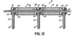
- FIG. 12is a view similar to FIG. 11 of a multi-level spinal stabilization system.
- a spine stiffening stabilization system 10includes a connecting element 12 coupled to and extending between a pair of vertebral anchors 14 .
- Each vertebral anchor 14is adapted to couple to either of two vertebras 16 in a patient's spine 18 .
- the connecting element 12With the connecting element 12 secured to the vertebral anchors 14 , the connecting element 12 maintains a restored disc space height and/or alignment between the adjacent vertebrae 16 .
- the connecting element 12preserves motion between the adjacent vertebrae 16 .
- the vertebral anchor 14is a polyaxial, top loading pedicle screw including a threaded shaft 20 adapted to be inserted into a pedicle area 22 of the vertebrae 16 .
- the vertebral anchorincludes a head 24 on the threaded shaft 20 and a saddle 26 is coupled to the head 24 and is adapted for polyaxial movement of the saddle 26 relative to the shaft 20 .
- the saddle 26having an exemplary U-shape provides a top loading capability to the vertebral anchor 14 so that the connecting element 12 may be inserted downwardly into the saddle 26 between a pair of polyaxial head receiving arms 28 .
- the saddle 26can be constructed with any desired shape.
- a securing member in the form of a threaded set screw 30mates with the saddle 26 to secure the connecting element 12 to the vertebral anchor 14 .
- Each receiving arm 28 of the U-shaped saddle 26has threads 32 which mate with the threads 34 on the set screw securing member 30 .
- a top loading polyaxial pedicle screwis shown and described herein as one embodiment of the vertebral anchor 14 , other types of vertebral anchors can readily be used within the scope of this invention including standard fixed pedicle screws, hooks or other devices intended to couple a connecting element to the vertebrae.
- one embodiment of the connecting element 12includes a central portion or member 36 and a pair of connecting portions or shanks 38 that include rod portions 39 that can be of any suitable shape to fit within the saddle 26 extending in opposite directions on the connecting element 12 .
- Each shank 38is coupled to one of the vertebral anchors 14 .
- the terminal ends of the shanks 38 of the various embodiments of this inventioncan be trimmed to length after sizing and installation.
- the connecting members 38can be pre-sized prior to implementation.
- the central member 36is concentrically surrounded by a flexible portion or brace 40 .
- the brace 40is positioned between spaced flanges 42 and the central member 36 is secured within the brace 40 and between the flanges 42 by crimping tabs 44 .
- the connecting element 12 of this inventionincludes a flexible intermediate portion 46 .
- the brace 40 and central member 36are intended for use in the intermediate portion 46 .
- a solid flexible corecan be used as the flexible intermediate portion 46 .
- the brace 40is an elastomeric member that allows for flexing of the connecting element 12 .
- the brace 40stabilizes the spine 18 while allowing for flexibility and axial dampening.
- the central member 36is tensioned and integral to the intermediate portion 46 of the connecting element 12 .
- the central member 36allows for bending of the shanks 38 and the associated forces on the brace 40 .
- the connecting element 12 of this inventionallows for flexing of the spinal stabilization system 10 in response to movement of the vertebrae 16 .
- the configuration and interaction of the various component parts of the connecting element 12 of FIGS. 1-3allows for bending of the connecting element 12 and the shanks 38 connected to the vertebral anchors 14 so that the central member 36 is placed under tension and one side of the brace 40 is compressed depending upon the orientation of the bending motion.
- FIG. 4a cross-sectional view of an alternative embodiment of the connecting element 12 according to this invention is shown in which the shanks 38 are connected to a pair of spaced outer flanges 42 between which the flexible brace 40 is positioned.
- the central member 36is embedded within the brace 40 and includes an additional pair of spaced inner flanges 48 between which a portion of the central member 36 is held by mechanical crimping tabs 44 or similar arrangement.
- Each of the inner flanges 48is mounted and spaced from an associated outer flange 42 by an extension 50 of the shank 38 extending into the brace 40 .
- the central member 36allows the shanks 38 and flanges 42 when bent to apply both compressive and tensile forces to the brace 40 as well as tension to the central member 36 .
- the central member 36may be made from a DacronTM tape woven cord, a braided stainless steel or titanium cable, carbon fiber, KevlarTM or a variety of other materials providing sufficient strength with low elongation characteristics.
- Other options for the central member 36include a synthetic or natural rubber woven cord which is stretched between the flanges 42 prior to attachment and mounting therein. The cord would be attached to the flanges 42 and then stretched into a mold cavity where the polymer or elastomer brace material would be injected into the mold so that the central cord would be in constant tension, but below its elastic limit.
- FIG. 5A further alternative embodiment of the connecting element 12 according to this invention is shown in FIG. 5 in which the central member 36 is surrounded by the brace 40 and oppositely extending shanks 38 mount the connecting element 12 to the respective vertebral anchors 14 .
- the central member 36 of FIG. 5may be en elastic mesh or woven member and the polymer material of the brace 40 would then be injection molded through the mesh and around the corded central member.
- the central member 36could be steel, titanium, nickel titanium alloy, polymer, carbon fiber or other materials.
- the connecting element 12is a flexible member that provides a shock absorbing effect in transmitting spinal column loads between the anchors 14 to which it is engaged.
- Intermediate portion 46 between the flanges 42can also permit relative movement to allow motion of the spinal column segment to which connecting element 12 is engaged.
- intermediate portion 46provides connecting element 12 with a variable stiffness profile between anchors 14 .
- FIG. 6For installation requiring more than one level of treatment, a two-level section system 10 such as the embodiment shown in FIG. 6 could be utilized.
- the construct of FIG. 6provides two flexible connecting elements 12 with a predetermined space between them.
- the length of the shank 38 positioned between the connecting elements 12 of the embodiment of FIG. 6could be fixed or a variable distance to accommodate different vertebral anatomies.
- FIG. 7A further alternative embodiment of a spinal stabilization stiffening system 10 according to this invention is shown in perspective view in FIG. 7 and cross-sectional view in FIG. 8 .
- the vertebral anchor 14 of the embodiment of FIGS. 7 and 8is shown as a pedicle screw having a threaded shaft 20 and a head 24 .
- the vertebral anchor 14 in one embodimentis a polyaxial pedicle screw similar to a device marketed by Zimmer Spine, Inc. as the ST360TM.
- the vertebral anchor 14includes an upwardly extending toggle 62 .
- the connecting element 12is mounted to the toggles 62 of the vertebral anchors 14 .
- the connecting element 12in one embodiment includes a central member 36 of an elastomeric or polymeric material providing flexibility to the construct.
- the central member 36is molded about a pair of rims 64 providing an aperture 66 so that the connecting element 12 may be mounted downwardly onto the toggles 62 and secured in place by a washer 68 and threaded nut 70 combination as shown in FIGS. 7 and 8 .
- FIGS. 9-11a further alternative embodiment of the connecting element 12 according to this invention is shown.
- flanges 38are provided with outwardly projecting annular hubs 52 and a securing element in the form of a setscrew 54 is seated within a threaded aperture 56 on the hub 52 to secure the flange 42 and hub 52 arrangement to the shank 38 of the connecting element 12 and against the brace 40 .
- the connecting elementcan be assembled pre- or intra-operatively. Once assembled, as shown in FIG. 10A , the connecting element 12 is positioned in the top loading vertebral anchors 14 and secured thereto by the vertebral anchor set screws 30 as shown in FIG. 10 B resulting in the arrangement and installation of FIG. 9 .
- the intermediate portion 46is of a different size than intermediate portion 46 of FIG. 1 and occupies more of the distance between the securing members 30 .
- a cross-sectional view of the connecting element 12 and associated vertebral anchors 14 of FIGS. 9-10Bis shown in FIG. 11 .
- a multi-level construct 10is provided with a generally H-shaped hub 58 having a duct 60 there through for the central member 36 to extend from one connecting element 12 to an adjacent connecting element 12 .
- the flanges 42can be adapted to engage the flexible brace 40 there between.
- flanges 42include holes to receive attachment means such as fasteners, sutures, threads, wires, or other devices to engage central member 36 to the respective flange 42 .
- the brace 40is injection molded between flanges 42 . The injected material can flow into holes in the central member 36 to form around central member 36 and at least partially around the flanges 42 to provide engagement therewith.
- intermediate portion 46is molded over flanges 42 .
- the connecting element 12can be provided with or without the central member 36 and with or without the flanges 42 .
- anchor 14is engageable to a first vertebra 16
- a second anchor 14is engageable to a second vertebra 16
- a third anchor 14is engageable to a third vertebra 16 .
- intermediate portion 46allows the vertebrae to which the anchors 14 are engaged to move or flex relative to one another, but limits extension and flexion motion to provide a stabilizing effect.
- Connecting element 12can be guided into position between the anchors 14 using an installation instrument as discussed above.
- the installation instrumentmay include extenders extending from any one, two or three of the anchors 14 .
- Other techniquescontemplate insertion with an open surgical technique, or guiding of the connecting element 12 distally along extenders extending proximally from one or more of the anchors 14 .
- Connecting element 12can be employed in fusion procedures or in procedures employing dynamic stabilization without fusion. In fusion procedures, fusion promoting material and/or one or more fusion devices, implants, or bone graft are placed in the disc space between adjacent vertebrae. In such procedures, a single level connecting element 12 may be coupled between the vertebrae if dynamic stabilization is desired. If rigid stabilization is desired, an elongated connecting element 12 can be provided and engaged between the vertebrae to be fused, and one or more adjacent vertebral levels can be dynamically stabilized with the intermediate portion 46 engaged between these or more other vertebral levels.
- the connecting elements 12are shown as being adapted to extend along one or two vertebral levels, the connecting elements 12 can also extend along three or more vertebral levels.
- one of the shanks 38can include a length that extends along multiple vertebral levels to be fused to provide rigid stabilization of these levels, while the other of the shanks 38 includes a length adapted to extend along at least one vertebral level to provide a flexible intermediate portion 46 between vertebrae 16 for dynamic stabilization.
- the flexible brace 40 discussed hereincan be made from any suitable material allowing at some motion of the vertebral level along which the intermediate portion 46 is engaged.
- the brace portions 40can be made from elastomers, polycarbonateurethane, polyetheretherketone, or other polymer material.
- the brace 40can be made from resorbable material.
- the brace 40include springs, which can be made from metal or other suitable material.
- the connecting element 12can be provided with a varying stiffness profiles to vary the stiffness properties of the system 10 and control movement of the one or more dynamically stabilized vertebral levels.
- Such varying stiffness profilescan be provided across the cross-section of a single flexible intermediate portion 46 of a particular connecting element 12 , or provided between different intermediate portions 46 of a single multi-level connecting element 12 , or provided between a number of connecting elements 12 in a kit where the connecting elements 12 includes one or more portions with a stiffness profile that varies relative to one or more of the portions of the other connecting elements 12 .
- the hardness characteristics of the material comprising the flexible brace 40is varied.
- the durometer of an elastomer material comprising the one or more flexible brace portions 40may vary to allow selection and implantation of a connecting element 12 providing the desired motion characteristics for the vertebral level.
- the connecting element 12is provided with a central member 36 that couples the first and second flanges 42 to one another through the flexible brace portion 40 .
- the diameter of the central member 36can be varied so that the connecting elements 12 with flexible brace portions 40 extending about a central member 36 with a greater diameter are stiffer than connecting elements 12 with a flexible brace portion 40 extending about a central member 36 of lesser diameter.
- the central member 36can be pre-tensioned so that the flanges 42 are compressed against the flexible brace portion 40 when engaged thereto.
- the amount of pre-tensioncan range from zero to the tensile break strength of the central member 36 .
- the greater pretension loading of the central member 36results in stiffer flexible brace portion 40 behavior since the preloading compresses the flexible brace portion 40 between the flanges 42 .
Landscapes
- Health & Medical Sciences (AREA)
- Orthopedic Medicine & Surgery (AREA)
- Life Sciences & Earth Sciences (AREA)
- Neurology (AREA)
- Surgery (AREA)
- Heart & Thoracic Surgery (AREA)
- Engineering & Computer Science (AREA)
- Biomedical Technology (AREA)
- Nuclear Medicine, Radiotherapy & Molecular Imaging (AREA)
- Medical Informatics (AREA)
- Molecular Biology (AREA)
- Animal Behavior & Ethology (AREA)
- General Health & Medical Sciences (AREA)
- Public Health (AREA)
- Veterinary Medicine (AREA)
- Prostheses (AREA)
- Surgical Instruments (AREA)
Abstract
Description
Claims (14)
Priority Applications (1)
| Application Number | Priority Date | Filing Date | Title |
|---|---|---|---|
| US12/247,612US8206422B2 (en) | 2007-01-02 | 2008-10-08 | Spine stiffening device and associated method |
Applications Claiming Priority (2)
| Application Number | Priority Date | Filing Date | Title |
|---|---|---|---|
| US11/618,943US8029544B2 (en) | 2007-01-02 | 2007-01-02 | Spine stiffening device |
| US12/247,612US8206422B2 (en) | 2007-01-02 | 2008-10-08 | Spine stiffening device and associated method |
Related Parent Applications (1)
| Application Number | Title | Priority Date | Filing Date |
|---|---|---|---|
| US11/618,943ContinuationUS8029544B2 (en) | 2007-01-02 | 2007-01-02 | Spine stiffening device |
Publications (2)
| Publication Number | Publication Date |
|---|---|
| US20090030464A1 US20090030464A1 (en) | 2009-01-29 |
| US8206422B2true US8206422B2 (en) | 2012-06-26 |
Family
ID=39589159
Family Applications (2)
| Application Number | Title | Priority Date | Filing Date |
|---|---|---|---|
| US11/618,943Expired - Fee RelatedUS8029544B2 (en) | 2007-01-02 | 2007-01-02 | Spine stiffening device |
| US12/247,612Expired - Fee RelatedUS8206422B2 (en) | 2007-01-02 | 2008-10-08 | Spine stiffening device and associated method |
Family Applications Before (1)
| Application Number | Title | Priority Date | Filing Date |
|---|---|---|---|
| US11/618,943Expired - Fee RelatedUS8029544B2 (en) | 2007-01-02 | 2007-01-02 | Spine stiffening device |
Country Status (5)
| Country | Link |
|---|---|
| US (2) | US8029544B2 (en) |
| EP (1) | EP2114272B1 (en) |
| AU (1) | AU2007340272B2 (en) |
| CA (1) | CA2674357A1 (en) |
| WO (1) | WO2008082737A2 (en) |
Cited By (23)
| Publication number | Priority date | Publication date | Assignee | Title |
|---|---|---|---|---|
| US20120109212A1 (en)* | 2007-01-30 | 2012-05-03 | Warsaw Orthopedic, Inc. | Collar bore configuration for dynamic spinal stabilization assembly |
| US20130072992A1 (en)* | 2009-06-15 | 2013-03-21 | Roger P. Jackson | Polyaxial bone anchor with pop-on shank and friction fit retainer with low profile edge lock |
| US20140018856A1 (en)* | 2005-08-24 | 2014-01-16 | Biedermann Technologies Gmbh & Co. Kg | Rod-shaped implant element for the application in spine surgery or trauma surgery and stabilization device with such a rod-shaped implant element |
| US9439683B2 (en) | 2007-01-26 | 2016-09-13 | Roger P Jackson | Dynamic stabilization member with molded connection |
| US9451993B2 (en) | 2014-01-09 | 2016-09-27 | Roger P. Jackson | Bi-radial pop-on cervical bone anchor |
| US9522021B2 (en) | 2004-11-23 | 2016-12-20 | Roger P. Jackson | Polyaxial bone anchor with retainer with notch for mono-axial motion |
| US9636146B2 (en) | 2012-01-10 | 2017-05-02 | Roger P. Jackson | Multi-start closures for open implants |
| US9662143B2 (en) | 2004-02-27 | 2017-05-30 | Roger P Jackson | Dynamic fixation assemblies with inner core and outer coil-like member |
| US9717533B2 (en) | 2013-12-12 | 2017-08-01 | Roger P. Jackson | Bone anchor closure pivot-splay control flange form guide and advancement structure |
| US9770265B2 (en) | 2012-11-21 | 2017-09-26 | Roger P. Jackson | Splay control closure for open bone anchor |
| US9883892B2 (en) | 2009-06-15 | 2018-02-06 | Roger P. Jackson | Polyaxial bone anchor with pop-on shank, friction fit retainer, winged insert and low profile edge lock |
| US9907574B2 (en) | 2008-08-01 | 2018-03-06 | Roger P. Jackson | Polyaxial bone anchors with pop-on shank, friction fit fully restrained retainer, insert and tool receiving features |
| US9924975B2 (en) | 2014-10-21 | 2018-03-27 | Roger P. Jackson | Bone anchor having a snap-fit assembly |
| US9956006B2 (en) | 2009-06-15 | 2018-05-01 | Roger P. Jackson | Pivotal bone anchor with snap-on receiver and insert deployment |
| US9980753B2 (en) | 2009-06-15 | 2018-05-29 | Roger P Jackson | pivotal anchor with snap-in-place insert having rotation blocking extensions |
| US10172649B2 (en) | 2009-06-15 | 2019-01-08 | Roger P. Jackson | Bottom-loaded pivotal bone anchor assembly with non-pivoting retainer and deployable insert |
| US10363070B2 (en) | 2009-06-15 | 2019-07-30 | Roger P. Jackson | Pivotal bone anchor assemblies with pressure inserts and snap on articulating retainers |
| US10543021B2 (en) | 2014-10-21 | 2020-01-28 | Roger P. Jackson | Pivotal bone anchor assembly having an open ring positioner for a retainer |
| US10987137B2 (en) | 2005-05-10 | 2021-04-27 | Roger P. Jackson | Pivotal bone anchor assembly with independent lock via insert compressing tool |
| US11147591B2 (en) | 2004-11-10 | 2021-10-19 | Roger P Jackson | Pivotal bone anchor receiver assembly with threaded closure |
| US11229457B2 (en) | 2009-06-15 | 2022-01-25 | Roger P. Jackson | Pivotal bone anchor assembly with insert tool deployment |
| US11464549B2 (en) | 2009-06-15 | 2022-10-11 | Roger P. Jackson | Pivotal bone anchor assembly with horizontal tool engagement grooves and insert with upright arms having flared outer portions |
| US11583318B2 (en) | 2018-12-21 | 2023-02-21 | Paradigm Spine, Llc | Modular spine stabilization system and associated instruments |
Families Citing this family (88)
| Publication number | Priority date | Publication date | Assignee | Title |
|---|---|---|---|---|
| FR2812185B1 (en)* | 2000-07-25 | 2003-02-28 | Spine Next Sa | SEMI-RIGID CONNECTION PIECE FOR RACHIS STABILIZATION |
| FR2812186B1 (en)* | 2000-07-25 | 2003-02-28 | Spine Next Sa | FLEXIBLE CONNECTION PIECE FOR SPINAL STABILIZATION |
| US10258382B2 (en) | 2007-01-18 | 2019-04-16 | Roger P. Jackson | Rod-cord dynamic connection assemblies with slidable bone anchor attachment members along the cord |
| US7862587B2 (en) | 2004-02-27 | 2011-01-04 | Jackson Roger P | Dynamic stabilization assemblies, tool set and method |
| US8292926B2 (en) | 2005-09-30 | 2012-10-23 | Jackson Roger P | Dynamic stabilization connecting member with elastic core and outer sleeve |
| US8353932B2 (en)* | 2005-09-30 | 2013-01-15 | Jackson Roger P | Polyaxial bone anchor assembly with one-piece closure, pressure insert and plastic elongate member |
| US10729469B2 (en) | 2006-01-09 | 2020-08-04 | Roger P. Jackson | Flexible spinal stabilization assembly with spacer having off-axis core member |
| US20160242816A9 (en) | 2001-05-09 | 2016-08-25 | Roger P. Jackson | Dynamic spinal stabilization assembly with elastic bumpers and locking limited travel closure mechanisms |
| US8876868B2 (en) | 2002-09-06 | 2014-11-04 | Roger P. Jackson | Helical guide and advancement flange with radially loaded lip |
| US7621918B2 (en) | 2004-11-23 | 2009-11-24 | Jackson Roger P | Spinal fixation tool set and method |
| US7377923B2 (en) | 2003-05-22 | 2008-05-27 | Alphatec Spine, Inc. | Variable angle spinal screw assembly |
| US8092500B2 (en)* | 2007-05-01 | 2012-01-10 | Jackson Roger P | Dynamic stabilization connecting member with floating core, compression spacer and over-mold |
| US7776067B2 (en) | 2005-05-27 | 2010-08-17 | Jackson Roger P | Polyaxial bone screw with shank articulation pressure insert and method |
| US8366753B2 (en) | 2003-06-18 | 2013-02-05 | Jackson Roger P | Polyaxial bone screw assembly with fixed retaining structure |
| US8926670B2 (en) | 2003-06-18 | 2015-01-06 | Roger P. Jackson | Polyaxial bone screw assembly |
| US7967850B2 (en) | 2003-06-18 | 2011-06-28 | Jackson Roger P | Polyaxial bone anchor with helical capture connection, insert and dual locking assembly |
| US7527638B2 (en) | 2003-12-16 | 2009-05-05 | Depuy Spine, Inc. | Methods and devices for minimally invasive spinal fixation element placement |
| US11419642B2 (en) | 2003-12-16 | 2022-08-23 | Medos International Sarl | Percutaneous access devices and bone anchor assemblies |
| US7179261B2 (en) | 2003-12-16 | 2007-02-20 | Depuy Spine, Inc. | Percutaneous access devices and bone anchor assemblies |
| US11241261B2 (en) | 2005-09-30 | 2022-02-08 | Roger P Jackson | Apparatus and method for soft spinal stabilization using a tensionable cord and releasable end structure |
| US8152810B2 (en) | 2004-11-23 | 2012-04-10 | Jackson Roger P | Spinal fixation tool set and method |
| JP2007525274A (en) | 2004-02-27 | 2007-09-06 | ロジャー・ピー・ジャクソン | Orthopedic implant rod reduction instrument set and method |
| US7160300B2 (en) | 2004-02-27 | 2007-01-09 | Jackson Roger P | Orthopedic implant rod reduction tool set and method |
| US7651502B2 (en) | 2004-09-24 | 2010-01-26 | Jackson Roger P | Spinal fixation tool set and method for rod reduction and fastener insertion |
| US8926672B2 (en) | 2004-11-10 | 2015-01-06 | Roger P. Jackson | Splay control closure for open bone anchor |
| US20120029568A1 (en)* | 2006-01-09 | 2012-02-02 | Jackson Roger P | Spinal connecting members with radiused rigid sleeves and tensioned cords |
| WO2006057837A1 (en) | 2004-11-23 | 2006-06-01 | Jackson Roger P | Spinal fixation tool attachment structure |
| US9216041B2 (en) | 2009-06-15 | 2015-12-22 | Roger P. Jackson | Spinal connecting members with tensioned cords and rigid sleeves for engaging compression inserts |
| WO2007038429A1 (en) | 2005-09-27 | 2007-04-05 | Endius, Inc. | Methods and apparatuses for stabilizing the spine through an access device |
| US20080140076A1 (en)* | 2005-09-30 | 2008-06-12 | Jackson Roger P | Dynamic stabilization connecting member with slitted segment and surrounding external elastomer |
| US8105368B2 (en)* | 2005-09-30 | 2012-01-31 | Jackson Roger P | Dynamic stabilization connecting member with slitted core and outer sleeve |
| US8034078B2 (en) | 2008-05-30 | 2011-10-11 | Globus Medical, Inc. | System and method for replacement of spinal motion segment |
| US20080294198A1 (en)* | 2006-01-09 | 2008-11-27 | Jackson Roger P | Dynamic spinal stabilization assembly with torsion and shear control |
| US7815663B2 (en)* | 2006-01-27 | 2010-10-19 | Warsaw Orthopedic, Inc. | Vertebral rods and methods of use |
| EP1815812B1 (en)* | 2006-02-03 | 2009-07-29 | Spinelab AG | Spinal implant |
| US7947045B2 (en)* | 2006-10-06 | 2011-05-24 | Zimmer Spine, Inc. | Spinal stabilization system with flexible guides |
| CA2670988C (en) | 2006-12-08 | 2014-03-25 | Roger P. Jackson | Tool system for dynamic spinal implants |
| US8475498B2 (en)* | 2007-01-18 | 2013-07-02 | Roger P. Jackson | Dynamic stabilization connecting member with cord connection |
| US11224463B2 (en) | 2007-01-18 | 2022-01-18 | Roger P. Jackson | Dynamic stabilization connecting member with pre-tensioned flexible core member |
| US8366745B2 (en) | 2007-05-01 | 2013-02-05 | Jackson Roger P | Dynamic stabilization assembly having pre-compressed spacers with differential displacements |
| US8012177B2 (en)* | 2007-02-12 | 2011-09-06 | Jackson Roger P | Dynamic stabilization assembly with frusto-conical connection |
| WO2008134703A2 (en)* | 2007-04-30 | 2008-11-06 | Globus Medical, Inc. | Flexible spine stabilization system |
| US10383660B2 (en)* | 2007-05-01 | 2019-08-20 | Roger P. Jackson | Soft stabilization assemblies with pretensioned cords |
| US9439681B2 (en) | 2007-07-20 | 2016-09-13 | DePuy Synthes Products, Inc. | Polyaxial bone fixation element |
| EP2178451A2 (en)* | 2007-08-07 | 2010-04-28 | Synthes GmbH | Dynamic cable system |
| US20090082815A1 (en)* | 2007-09-20 | 2009-03-26 | Zimmer Gmbh | Spinal stabilization system with transition member |
| US20090093843A1 (en)* | 2007-10-05 | 2009-04-09 | Lemoine Jeremy J | Dynamic spine stabilization system |
| EP2047812B1 (en) | 2007-10-11 | 2011-12-14 | BIEDERMANN MOTECH GmbH | Bone anchoring device |
| US20090105764A1 (en)* | 2007-10-23 | 2009-04-23 | Jackson Roger P | Dynamic stabilization member with fin support and solid core extension |
| US8911477B2 (en)* | 2007-10-23 | 2014-12-16 | Roger P. Jackson | Dynamic stabilization member with end plate support and cable core extension |
| US9232968B2 (en)* | 2007-12-19 | 2016-01-12 | DePuy Synthes Products, Inc. | Polymeric pedicle rods and methods of manufacturing |
| USD620109S1 (en) | 2008-02-05 | 2010-07-20 | Zimmer Spine, Inc. | Surgical installation tool |
| US20240090924A1 (en)* | 2008-04-18 | 2024-03-21 | Roger P. Jackson | Longitudinal connecting member with sleeved tensioned cords |
| US20090326583A1 (en)* | 2008-06-25 | 2009-12-31 | Missoum Moumene | Posterior Dynamic Stabilization System With Flexible Ligament |
| JP5815407B2 (en) | 2008-09-12 | 2015-11-17 | ジンテス ゲゼルシャフト ミット ベシュレンクテル ハフツング | Spinal stabilization and guided fixation system |
| US20100114165A1 (en)* | 2008-11-04 | 2010-05-06 | Abbott Spine, Inc. | Posterior dynamic stabilization system with pivoting collars |
| US20100137908A1 (en)* | 2008-12-01 | 2010-06-03 | Zimmer Spine, Inc. | Dynamic Stabilization System Components Including Readily Visualized Polymeric Compositions |
| US9055979B2 (en)* | 2008-12-03 | 2015-06-16 | Zimmer Gmbh | Cord for vertebral fixation having multiple stiffness phases |
| US8137355B2 (en) | 2008-12-12 | 2012-03-20 | Zimmer Spine, Inc. | Spinal stabilization installation instrumentation and methods |
| IT1392200B1 (en)* | 2008-12-17 | 2012-02-22 | N B R New Biotechnology Res | MODULAR VERTEBRAL STABILIZER. |
| US8137356B2 (en)* | 2008-12-29 | 2012-03-20 | Zimmer Spine, Inc. | Flexible guide for insertion of a vertebral stabilization system |
| US8641734B2 (en)* | 2009-02-13 | 2014-02-04 | DePuy Synthes Products, LLC | Dual spring posterior dynamic stabilization device with elongation limiting elastomers |
| US8118840B2 (en) | 2009-02-27 | 2012-02-21 | Warsaw Orthopedic, Inc. | Vertebral rod and related method of manufacture |
| KR20120013312A (en) | 2009-04-15 | 2012-02-14 | 신세스 게엠바하 | Orthodontic Connectors for Spinal Structures |
| US8292927B2 (en)* | 2009-04-24 | 2012-10-23 | Warsaw Orthopedic, Inc. | Flexible articulating spinal rod |
| US8998959B2 (en) | 2009-06-15 | 2015-04-07 | Roger P Jackson | Polyaxial bone anchors with pop-on shank, fully constrained friction fit retainer and lock and release insert |
| US9668771B2 (en) | 2009-06-15 | 2017-06-06 | Roger P Jackson | Soft stabilization assemblies with off-set connector |
| CA2764841A1 (en)* | 2009-06-17 | 2010-12-23 | Synthes Usa, Llc | Revision connector for spinal constructs |
| US9320543B2 (en)* | 2009-06-25 | 2016-04-26 | DePuy Synthes Products, Inc. | Posterior dynamic stabilization device having a mobile anchor |
| US20110009906A1 (en)* | 2009-07-13 | 2011-01-13 | Zimmer Spine, Inc. | Vertebral stabilization transition connector |
| US8105360B1 (en) | 2009-07-16 | 2012-01-31 | Orthonex LLC | Device for dynamic stabilization of the spine |
| US9011494B2 (en)* | 2009-09-24 | 2015-04-21 | Warsaw Orthopedic, Inc. | Composite vertebral rod system and methods of use |
| US20110098748A1 (en)* | 2009-10-26 | 2011-04-28 | Warsaw Orthopedic, Inc. | Adjustable vertebral rod system and methods of use |
| US20110106162A1 (en)* | 2009-10-30 | 2011-05-05 | Warsaw Orthopedic, Inc. | Composite Connecting Elements for Spinal Stabilization Systems |
| US8328849B2 (en)* | 2009-12-01 | 2012-12-11 | Zimmer Gmbh | Cord for vertebral stabilization system |
| US9445844B2 (en)* | 2010-03-24 | 2016-09-20 | DePuy Synthes Products, Inc. | Composite material posterior dynamic stabilization spring rod |
| US8740945B2 (en) | 2010-04-07 | 2014-06-03 | Zimmer Spine, Inc. | Dynamic stabilization system using polyaxial screws |
| US20110257685A1 (en)* | 2010-04-15 | 2011-10-20 | Hay J Scott | Pre-stressed spinal stabilization system |
| US8382803B2 (en) | 2010-08-30 | 2013-02-26 | Zimmer Gmbh | Vertebral stabilization transition connector |
| AU2011299558A1 (en) | 2010-09-08 | 2013-05-02 | Roger P. Jackson | Dynamic stabilization members with elastic and inelastic sections |
| US8721566B2 (en) | 2010-11-12 | 2014-05-13 | Robert A. Connor | Spinal motion measurement device |
| US10058354B2 (en) | 2013-01-28 | 2018-08-28 | Roger P. Jackson | Pivotal bone anchor assembly with frictional shank head seating surfaces |
| US8852239B2 (en) | 2013-02-15 | 2014-10-07 | Roger P Jackson | Sagittal angle screw with integral shank and receiver |
| US9566092B2 (en) | 2013-10-29 | 2017-02-14 | Roger P. Jackson | Cervical bone anchor with collet retainer and outer locking sleeve |
| US10064658B2 (en) | 2014-06-04 | 2018-09-04 | Roger P. Jackson | Polyaxial bone anchor with insert guides |
| US9597119B2 (en) | 2014-06-04 | 2017-03-21 | Roger P. Jackson | Polyaxial bone anchor with polymer sleeve |
| KR102836394B1 (en)* | 2023-02-02 | 2025-07-22 | 박경우 | Bio-flexible spinal fixation apparatus to prevent fatigue fracture |
| CN118415733B (en)* | 2024-04-26 | 2025-01-03 | 中国人民解放军总医院第六医学中心 | Variable-rigidity fixing rod for spinal surgery |
Citations (103)
| Publication number | Priority date | Publication date | Assignee | Title |
|---|---|---|---|---|
| US2296793A (en) | 1942-02-02 | 1942-09-22 | Harry M Kirschbaum | Surgical retractor |
| US2840070A (en) | 1956-03-09 | 1958-06-24 | Benjamin F Tofflemire | Light-directing surgical retractor instrument |
| US4052980A (en) | 1976-06-10 | 1977-10-11 | Guenter A. Grams | Triaxial fiberoptic soft tissue retractor |
| US4226228A (en) | 1978-11-02 | 1980-10-07 | Shin Hee J | Multiple joint retractor with light |
| US4337763A (en) | 1980-04-21 | 1982-07-06 | The United States Of America As Represented By The Department Of Health, Education And Welfare | Illuminated surgical instrument |
| US4562832A (en) | 1984-01-21 | 1986-01-07 | Wilder Joseph R | Medical instrument and light pipe illumination assembly |
| US4597030A (en) | 1985-01-31 | 1986-06-24 | American Hospital Supply Corporation | Surgical illuminator |
| US4784150A (en) | 1986-11-04 | 1988-11-15 | Research Corporation | Surgical retractor and blood flow monitor |
| US4945896A (en) | 1989-01-24 | 1990-08-07 | Gade George F | Surgical retractor assembly having tissue viability sensor embedded therein |
| US5030220A (en) | 1990-03-29 | 1991-07-09 | Advanced Spine Fixation Systems Incorporated | Spine fixation system |
| US5035232A (en) | 1987-10-24 | 1991-07-30 | Aesculap Ag | Retractor |
| US5159921A (en) | 1990-11-27 | 1992-11-03 | Hoover Rocklin L | Surgical retractor |
| FR2676911A1 (en) | 1991-05-30 | 1992-12-04 | Psi Ste Civile Particuliere | INTERVERTEBRAL STABILIZATION DEVICE WITH SHOCK ABSORBERS. |
| US5237985A (en) | 1992-06-22 | 1993-08-24 | Crystal Wind, Inc. | Uterine retractor |
| WO1994017745A1 (en) | 1993-02-09 | 1994-08-18 | Plus Endoprothetik Ag | Device for stiffening and/or correcting the spine |
| US5353786A (en) | 1992-01-24 | 1994-10-11 | Wilk Peter J | Surgical lighting method |
| US5375823A (en) | 1992-06-25 | 1994-12-27 | Societe Psi | Application of an improved damper to an intervertebral stabilization device |
| US5431153A (en) | 1993-06-11 | 1995-07-11 | Lee; Hans | Surgical apparatus for assisting in the release of the carpal tunnel |
| WO1995019149A1 (en) | 1994-01-18 | 1995-07-20 | Safir S.A.R.L. | Global vertebral fixation device |
| EP0669109A1 (en) | 1994-02-28 | 1995-08-30 | SULZER Medizinaltechnik AG | Stabilizer for adjacent vertebrae |
| US5451227A (en) | 1989-04-24 | 1995-09-19 | Michaelson; Gary K. | Thin foot plate multi bite rongeur |
| US5496318A (en) | 1993-01-08 | 1996-03-05 | Advanced Spine Fixation Systems, Inc. | Interspinous segmental spine fixation device |
| US5520611A (en) | 1993-12-16 | 1996-05-28 | Rao; Shekar | Illuminated retractor |
| FR2730405A1 (en) | 1995-02-10 | 1996-08-14 | Moreau Patrice | Spinal column prosthesis |
| US5558622A (en) | 1994-09-02 | 1996-09-24 | Greenberg Surgical Technologies, Llc | Mandibular border retractor and method for fixating a fractured mandible |
| US5569258A (en) | 1995-06-22 | 1996-10-29 | Logan Instruments, Inc. | Laminectomy rongeurs |
| US5584831A (en) | 1993-07-09 | 1996-12-17 | September 28, Inc. | Spinal fixation device and method |
| US5611800A (en) | 1994-02-15 | 1997-03-18 | Alphatec Manufacturing, Inc. | Spinal fixation system |
| US5645599A (en) | 1994-07-26 | 1997-07-08 | Fixano | Interspinal vertebral implant |
| US5653713A (en) | 1989-04-24 | 1997-08-05 | Michelson; Gary Karlin | Surgical rongeur |
| US5725582A (en) | 1992-08-19 | 1998-03-10 | Surgicraft Limited | Surgical implants |
| FR2755844A1 (en) | 1996-11-15 | 1998-05-22 | Stryker France Sa | ELASTICALLY DEFORMED OSTEOSYNTHESIS SYSTEM FOR SPINE |
| US5755660A (en) | 1995-10-31 | 1998-05-26 | Tyagi; Narendra S. | Combination surgical retractor, light source, spreader, and suction apparatus |
| US5836948A (en) | 1997-01-02 | 1998-11-17 | Saint Francis Medical Technologies, Llc | Spine distraction implant and method |
| WO1999005980A1 (en) | 1997-07-31 | 1999-02-11 | Plus Endoprothetik Ag | Device for stiffening and/or correcting a vertebral column or such like |
| US5928139A (en) | 1998-04-24 | 1999-07-27 | Koros; Tibor B. | Retractor with adjustable length blades and light pipe guides |
| US5928140A (en) | 1997-09-02 | 1999-07-27 | Hardten; David R. | Illuminated iris retractor probe system |
| WO1999044527A1 (en) | 1998-03-04 | 1999-09-10 | Dimso (Distribution Medicale Du Sud-Ouest) | Backbone osteosynthesis system with ligament |
| US5961516A (en) | 1996-08-01 | 1999-10-05 | Graf; Henry | Device for mechanically connecting and assisting vertebrae with respect to one another |
| US5967971A (en) | 1998-04-14 | 1999-10-19 | Bolser; Jeffrey William | Surgical instrument |
| US6042538A (en) | 1998-11-18 | 2000-03-28 | Emory University | Device for endoscopic vessel harvesting |
| US6048342A (en) | 1997-01-02 | 2000-04-11 | St. Francis Medical Technologies, Inc. | Spine distraction implant |
| US6080105A (en) | 1997-06-26 | 2000-06-27 | Spears; Robert A. | Illuminated dental and surgical retractor and kit including plurality of blades and blades recharging base |
| US6139493A (en) | 1998-07-08 | 2000-10-31 | Koros; Tibor B. | Retractor with adjustable length blades and light pipe guides |
| US6193651B1 (en) | 1995-10-20 | 2001-02-27 | United States Surgical Corporation | Surgical retractor |
| US6196968B1 (en) | 1997-06-02 | 2001-03-06 | General Surgical Innovations, Inc. | Direct vision subcutaneous tissue retractor and method for use |
| US6210325B1 (en) | 1998-10-02 | 2001-04-03 | Minnesota Scientific, Inc. | Cam-activated adjustable arm and illuminated tubular retractor |
| US6228024B1 (en) | 1997-06-02 | 2001-05-08 | General Surgical Innovations, Inc. | Vascular retractor |
| US6241730B1 (en) | 1997-11-26 | 2001-06-05 | Scient'x (Societe A Responsabilite Limitee) | Intervertebral link device capable of axial and angular displacement |
| US6263133B1 (en) | 1999-03-29 | 2001-07-17 | Scimed Life Systems, Inc. | Optical focusing, collimating and coupling systems for use with single mode optical fiber |
| US6322499B1 (en) | 2000-01-20 | 2001-11-27 | Genzyme Corporation | Pivotal and illuminated saphenous vein retractor |
| US20020035366A1 (en) | 2000-09-18 | 2002-03-21 | Reto Walder | Pedicle screw for intervertebral support elements |
| US20020052603A1 (en) | 1999-03-30 | 2002-05-02 | Surgical Dynamics, Inc. | Apparatus for spinal stabilization |
| USD458680S1 (en) | 2001-08-06 | 2002-06-11 | Alan M. Engler | Illuminated retractor |
| US6428473B1 (en) | 2000-02-18 | 2002-08-06 | Genzyme Corporation | Illuminated rectal retractor |
| US6440169B1 (en) | 1998-02-10 | 2002-08-27 | Dimso | Interspinous stabilizer to be fixed to spinous processes of two vertebrae |
| US6451019B1 (en) | 1998-10-20 | 2002-09-17 | St. Francis Medical Technologies, Inc. | Supplemental spine fixation device and method |
| US6461359B1 (en) | 1999-11-10 | 2002-10-08 | Clifford Tribus | Spine stabilization device |
| US6468206B1 (en) | 1998-05-01 | 2002-10-22 | Genzyme Corporation | Illuminated surgical retractor |
| US6520979B1 (en) | 1998-04-29 | 2003-02-18 | Thierry Loubens | Linking device for surgical instrument |
| US6530929B1 (en) | 1999-10-20 | 2003-03-11 | Sdgi Holdings, Inc. | Instruments for stabilization of bony structures |
| US6554768B1 (en) | 2000-09-05 | 2003-04-29 | Genzyme Corporation | Illuminated deep pelvic retractor |
| US20030095781A1 (en) | 1997-07-02 | 2003-05-22 | Williams Jeffrey B. | Illuminated surgical retractor |
| US6582433B2 (en) | 2001-04-09 | 2003-06-24 | St. Francis Medical Technologies, Inc. | Spine fixation device and method |
| US6591049B2 (en) | 1997-07-02 | 2003-07-08 | Lumitex, Inc. | Light delivery systems and applications thereof |
| US20030220547A1 (en) | 2002-05-23 | 2003-11-27 | Holland Donna D. | Pivotal and illuminated saphenous vein retractor with tapered design |
| US20030220643A1 (en)* | 2002-05-24 | 2003-11-27 | Ferree Bret A. | Devices to prevent spinal extension |
| US6676706B1 (en) | 2000-04-26 | 2004-01-13 | Zimmer Technology, Inc. | Method and apparatus for performing a minimally invasive total hip arthroplasty |
| WO2004004549A2 (en) | 2002-07-10 | 2004-01-15 | Joseph Aferzon | Spinal support coupling device |
| FR2844180A1 (en) | 2002-09-11 | 2004-03-12 | Spinevision | Connection element for spinal fixation system designed to link at least two implantable connection assemblies, is formed from a helicoidal spring part and a polymeric material support part |
| US6743257B2 (en) | 2000-12-19 | 2004-06-01 | Cortek, Inc. | Dynamic implanted intervertebral spacer |
| US20040143169A1 (en) | 2002-08-02 | 2004-07-22 | Branch Charles L. | Systems and techniques for illuminating a surgical space |
| US6793656B1 (en) | 1992-03-17 | 2004-09-21 | Sdgi Holdings, Inc. | Systems and methods for fixation of adjacent vertebrae |
| US20050065516A1 (en) | 2003-09-24 | 2005-03-24 | Tae-Ahn Jahng | Method and apparatus for flexible fixation of a spine |
| US20050065514A1 (en)* | 2001-12-07 | 2005-03-24 | Armin Studer | Damping element |
| EP1523949A1 (en) | 2003-10-17 | 2005-04-20 | BIEDERMANN MOTECH GmbH | Surgical rod element, stabilisation device, and method of manufacturing the element |
| WO2005037150A1 (en) | 2003-10-16 | 2005-04-28 | Osteotech, Inc. | System and method for flexible correction of bony motion segment |
| US20050124991A1 (en) | 2003-12-05 | 2005-06-09 | Tae-Ahn Jahng | Method and apparatus for flexible fixation of a spine |
| US20050143737A1 (en) | 2003-12-31 | 2005-06-30 | John Pafford | Dynamic spinal stabilization system |
| US20050154390A1 (en) | 2003-11-07 | 2005-07-14 | Lutz Biedermann | Stabilization device for bones comprising a spring element and manufacturing method for said spring element |
| US20050165396A1 (en)* | 2001-07-18 | 2005-07-28 | Frederic Fortin | Flexible vertebral linking device |
| US20050171540A1 (en) | 2004-01-30 | 2005-08-04 | Roy Lim | Instruments and methods for minimally invasive spinal stabilization |
| FR2867057A1 (en) | 2004-03-02 | 2005-09-09 | Spinevision | Connecting element, useful for a spinal fixing system to connect two entire implantable connection bodies comprises a cable and a polymer envelope surrounding the cable |
| US20050203517A1 (en)* | 2003-09-24 | 2005-09-15 | N Spine, Inc. | Spinal stabilization device |
| US20050277922A1 (en)* | 2004-06-09 | 2005-12-15 | Trieu Hai H | Systems and methods for flexible spinal stabilization |
| US20050277928A1 (en) | 2004-06-14 | 2005-12-15 | Boschert Paul F | Spinal implant fixation assembly |
| US6986771B2 (en) | 2003-05-23 | 2006-01-17 | Globus Medical, Inc. | Spine stabilization system |
| US20060084982A1 (en) | 2004-10-20 | 2006-04-20 | The Board Of Trustees Of The Leland Stanford Junior University | Systems and methods for posterior dynamic stabilization of the spine |
| US20060111715A1 (en) | 2004-02-27 | 2006-05-25 | Jackson Roger P | Dynamic stabilization assemblies, tool set and method |
| WO2006066685A1 (en) | 2004-12-17 | 2006-06-29 | Zimmer Gmbh | Intervertebral stabilisation system |
| US20060212033A1 (en) | 2005-03-03 | 2006-09-21 | Accin Corporation | Vertebral stabilization using flexible rods |
| US20070005063A1 (en) | 2005-06-20 | 2007-01-04 | Sdgi Holdings, Inc. | Multi-level multi-functional spinal stabilization systems and methods |
| US20070016200A1 (en) | 2003-04-09 | 2007-01-18 | Jackson Roger P | Dynamic stabilization medical implant assemblies and methods |
| US20070055244A1 (en) | 2004-02-27 | 2007-03-08 | Jackson Roger P | Dynamic fixation assemblies with inner core and outer coil-like member |
| US20070198088A1 (en) | 2003-10-17 | 2007-08-23 | Lutz Biedermann | Flexible implant |
| US20070270860A1 (en) | 2005-09-30 | 2007-11-22 | Jackson Roger P | Dynamic stabilization connecting member with slitted core and outer sleeve |
| US20070293862A1 (en) | 2005-09-30 | 2007-12-20 | Jackson Roger P | Dynamic stabilization connecting member with elastic core and outer sleeve |
| WO2008006098A2 (en) | 2006-07-07 | 2008-01-10 | Warsaw Orthopedic, Inc. | Dynamic constructs for spinal stablization |
| US20080091213A1 (en) | 2004-02-27 | 2008-04-17 | Jackson Roger P | Tool system for dynamic spinal implants |
| US20080140076A1 (en) | 2005-09-30 | 2008-06-12 | Jackson Roger P | Dynamic stabilization connecting member with slitted segment and surrounding external elastomer |
| US20080147122A1 (en) | 2006-10-12 | 2008-06-19 | Jackson Roger P | Dynamic stabilization connecting member with molded inner segment and surrounding external elastomer |
| US7815664B2 (en)* | 2005-01-04 | 2010-10-19 | Warsaw Orthopedic, Inc. | Systems and methods for spinal stabilization with flexible elements |
| US7942905B2 (en)* | 2006-04-20 | 2011-05-17 | Warsaw Orthopedic, Inc. | Vertebral stabilizer |
Family Cites Families (4)
| Publication number | Priority date | Publication date | Assignee | Title |
|---|---|---|---|---|
| US2676911A (en)* | 1952-06-04 | 1954-04-27 | Olin Mathieson | Production of anhydrous hydrazine by extractive distillation with lower alkyl monoethers of diethylene glycol |
| US2730405A (en)* | 1952-07-14 | 1956-01-10 | Clyne E Stoops | Spraying device |
| US2755844A (en)* | 1955-05-18 | 1956-07-24 | American Seating Co | Chair with pivoted back |
| US20070270660A1 (en)* | 2006-03-29 | 2007-11-22 | Caylor Edward J Iii | System and method for determining a location of an orthopaedic medical device |
- 2007
- 2007-01-02USUS11/618,943patent/US8029544B2/ennot_activeExpired - Fee Related
- 2007-10-12EPEP07853993.9Apatent/EP2114272B1/ennot_activeNot-in-force
- 2007-10-12CACA002674357Apatent/CA2674357A1/ennot_activeAbandoned
- 2007-10-12AUAU2007340272Apatent/AU2007340272B2/ennot_activeExpired - Fee Related
- 2007-10-12WOPCT/US2007/081218patent/WO2008082737A2/enactiveApplication Filing
- 2008
- 2008-10-08USUS12/247,612patent/US8206422B2/ennot_activeExpired - Fee Related
Patent Citations (124)
| Publication number | Priority date | Publication date | Assignee | Title |
|---|---|---|---|---|
| US2296793A (en) | 1942-02-02 | 1942-09-22 | Harry M Kirschbaum | Surgical retractor |
| US2840070A (en) | 1956-03-09 | 1958-06-24 | Benjamin F Tofflemire | Light-directing surgical retractor instrument |
| US4052980A (en) | 1976-06-10 | 1977-10-11 | Guenter A. Grams | Triaxial fiberoptic soft tissue retractor |
| US4226228A (en) | 1978-11-02 | 1980-10-07 | Shin Hee J | Multiple joint retractor with light |
| US4337763A (en) | 1980-04-21 | 1982-07-06 | The United States Of America As Represented By The Department Of Health, Education And Welfare | Illuminated surgical instrument |
| US4562832A (en) | 1984-01-21 | 1986-01-07 | Wilder Joseph R | Medical instrument and light pipe illumination assembly |
| US4597030A (en) | 1985-01-31 | 1986-06-24 | American Hospital Supply Corporation | Surgical illuminator |
| US4784150A (en) | 1986-11-04 | 1988-11-15 | Research Corporation | Surgical retractor and blood flow monitor |
| US5035232A (en) | 1987-10-24 | 1991-07-30 | Aesculap Ag | Retractor |
| US4945896A (en) | 1989-01-24 | 1990-08-07 | Gade George F | Surgical retractor assembly having tissue viability sensor embedded therein |
| US5451227A (en) | 1989-04-24 | 1995-09-19 | Michaelson; Gary K. | Thin foot plate multi bite rongeur |
| US20030216740A1 (en) | 1989-04-24 | 2003-11-20 | Gary Karlin Michelson | Method for using a surgical rongeur |
| US5653713A (en) | 1989-04-24 | 1997-08-05 | Michelson; Gary Karlin | Surgical rongeur |
| US6575977B1 (en) | 1989-04-24 | 2003-06-10 | Gary Karlin Michelson | Surgical rongeur |
| US6142997A (en) | 1989-04-24 | 2000-11-07 | Gary Karlin Michelson | Surgical rongeur |
| US5030220A (en) | 1990-03-29 | 1991-07-09 | Advanced Spine Fixation Systems Incorporated | Spine fixation system |
| US5159921A (en) | 1990-11-27 | 1992-11-03 | Hoover Rocklin L | Surgical retractor |
| FR2676911A1 (en) | 1991-05-30 | 1992-12-04 | Psi Ste Civile Particuliere | INTERVERTEBRAL STABILIZATION DEVICE WITH SHOCK ABSORBERS. |
| US5540688A (en) | 1991-05-30 | 1996-07-30 | Societe "Psi" | Intervertebral stabilization device incorporating dampers |
| US5353786A (en) | 1992-01-24 | 1994-10-11 | Wilk Peter J | Surgical lighting method |
| US6793656B1 (en) | 1992-03-17 | 2004-09-21 | Sdgi Holdings, Inc. | Systems and methods for fixation of adjacent vertebrae |
| US5237985A (en) | 1992-06-22 | 1993-08-24 | Crystal Wind, Inc. | Uterine retractor |
| US5375823A (en) | 1992-06-25 | 1994-12-27 | Societe Psi | Application of an improved damper to an intervertebral stabilization device |
| US5725582A (en) | 1992-08-19 | 1998-03-10 | Surgicraft Limited | Surgical implants |
| US5496318A (en) | 1993-01-08 | 1996-03-05 | Advanced Spine Fixation Systems, Inc. | Interspinous segmental spine fixation device |
| WO1994017745A1 (en) | 1993-02-09 | 1994-08-18 | Plus Endoprothetik Ag | Device for stiffening and/or correcting the spine |
| US5562660A (en) | 1993-02-09 | 1996-10-08 | Plus Endoprothetik Ag | Apparatus for stiffening and/or correcting the vertebral column |
| US5431153A (en) | 1993-06-11 | 1995-07-11 | Lee; Hans | Surgical apparatus for assisting in the release of the carpal tunnel |
| US5584831A (en) | 1993-07-09 | 1996-12-17 | September 28, Inc. | Spinal fixation device and method |
| US5520611A (en) | 1993-12-16 | 1996-05-28 | Rao; Shekar | Illuminated retractor |
| WO1995019149A1 (en) | 1994-01-18 | 1995-07-20 | Safir S.A.R.L. | Global vertebral fixation device |
| FR2715057A1 (en) | 1994-01-18 | 1995-07-21 | Breard Francis Henri | Overall device for stabilizing the spine. |
| US5611800A (en) | 1994-02-15 | 1997-03-18 | Alphatec Manufacturing, Inc. | Spinal fixation system |
| EP0669109A1 (en) | 1994-02-28 | 1995-08-30 | SULZER Medizinaltechnik AG | Stabilizer for adjacent vertebrae |
| EP0669109B1 (en) | 1994-02-28 | 1999-05-26 | Sulzer Orthopädie AG | Stabilizer for adjacent vertebrae |
| US5645599A (en) | 1994-07-26 | 1997-07-08 | Fixano | Interspinal vertebral implant |
| US5558622A (en) | 1994-09-02 | 1996-09-24 | Greenberg Surgical Technologies, Llc | Mandibular border retractor and method for fixating a fractured mandible |
| FR2730405A1 (en) | 1995-02-10 | 1996-08-14 | Moreau Patrice | Spinal column prosthesis |
| US5569258A (en) | 1995-06-22 | 1996-10-29 | Logan Instruments, Inc. | Laminectomy rongeurs |
| US6193651B1 (en) | 1995-10-20 | 2001-02-27 | United States Surgical Corporation | Surgical retractor |
| US5755660A (en) | 1995-10-31 | 1998-05-26 | Tyagi; Narendra S. | Combination surgical retractor, light source, spreader, and suction apparatus |
| US5961516A (en) | 1996-08-01 | 1999-10-05 | Graf; Henry | Device for mechanically connecting and assisting vertebrae with respect to one another |
| FR2755844A1 (en) | 1996-11-15 | 1998-05-22 | Stryker France Sa | ELASTICALLY DEFORMED OSTEOSYNTHESIS SYSTEM FOR SPINE |
| US6419676B1 (en) | 1997-01-02 | 2002-07-16 | St. Francis Medical Technologies, Inc. | Spine distraction implant and method |
| US6235030B1 (en) | 1997-01-02 | 2001-05-22 | St. Francis Medical Technologies, Inc. | Spine distraction implant |
| US6048342A (en) | 1997-01-02 | 2000-04-11 | St. Francis Medical Technologies, Inc. | Spine distraction implant |
| US5836948A (en) | 1997-01-02 | 1998-11-17 | Saint Francis Medical Technologies, Llc | Spine distraction implant and method |
| US6196968B1 (en) | 1997-06-02 | 2001-03-06 | General Surgical Innovations, Inc. | Direct vision subcutaneous tissue retractor and method for use |
| US6228024B1 (en) | 1997-06-02 | 2001-05-08 | General Surgical Innovations, Inc. | Vascular retractor |
| US6080105A (en) | 1997-06-26 | 2000-06-27 | Spears; Robert A. | Illuminated dental and surgical retractor and kit including plurality of blades and blades recharging base |
| US20030095781A1 (en) | 1997-07-02 | 2003-05-22 | Williams Jeffrey B. | Illuminated surgical retractor |
| US6591049B2 (en) | 1997-07-02 | 2003-07-08 | Lumitex, Inc. | Light delivery systems and applications thereof |
| US6290700B1 (en) | 1997-07-31 | 2001-09-18 | Plus Endoprothetik Ag | Device for stiffening and/or correcting a vertebral column or such like |
| WO1999005980A1 (en) | 1997-07-31 | 1999-02-11 | Plus Endoprothetik Ag | Device for stiffening and/or correcting a vertebral column or such like |
| US5928140A (en) | 1997-09-02 | 1999-07-27 | Hardten; David R. | Illuminated iris retractor probe system |
| US6241730B1 (en) | 1997-11-26 | 2001-06-05 | Scient'x (Societe A Responsabilite Limitee) | Intervertebral link device capable of axial and angular displacement |
| US6440169B1 (en) | 1998-02-10 | 2002-08-27 | Dimso | Interspinous stabilizer to be fixed to spinous processes of two vertebrae |
| WO1999044527A1 (en) | 1998-03-04 | 1999-09-10 | Dimso (Distribution Medicale Du Sud-Ouest) | Backbone osteosynthesis system with ligament |
| US5967971A (en) | 1998-04-14 | 1999-10-19 | Bolser; Jeffrey William | Surgical instrument |
| US5928139A (en) | 1998-04-24 | 1999-07-27 | Koros; Tibor B. | Retractor with adjustable length blades and light pipe guides |
| US6520979B1 (en) | 1998-04-29 | 2003-02-18 | Thierry Loubens | Linking device for surgical instrument |
| US6468206B1 (en) | 1998-05-01 | 2002-10-22 | Genzyme Corporation | Illuminated surgical retractor |
| US6482153B1 (en) | 1998-05-01 | 2002-11-19 | Genzyme Corporation | Illuminated surgical retractor |
| US6139493A (en) | 1998-07-08 | 2000-10-31 | Koros; Tibor B. | Retractor with adjustable length blades and light pipe guides |
| US6210325B1 (en) | 1998-10-02 | 2001-04-03 | Minnesota Scientific, Inc. | Cam-activated adjustable arm and illuminated tubular retractor |
| US6451019B1 (en) | 1998-10-20 | 2002-09-17 | St. Francis Medical Technologies, Inc. | Supplemental spine fixation device and method |
| US6042538A (en) | 1998-11-18 | 2000-03-28 | Emory University | Device for endoscopic vessel harvesting |
| US6263133B1 (en) | 1999-03-29 | 2001-07-17 | Scimed Life Systems, Inc. | Optical focusing, collimating and coupling systems for use with single mode optical fiber |
| US20020052603A1 (en) | 1999-03-30 | 2002-05-02 | Surgical Dynamics, Inc. | Apparatus for spinal stabilization |
| US6530929B1 (en) | 1999-10-20 | 2003-03-11 | Sdgi Holdings, Inc. | Instruments for stabilization of bony structures |
| US6461359B1 (en) | 1999-11-10 | 2002-10-08 | Clifford Tribus | Spine stabilization device |
| US6322499B1 (en) | 2000-01-20 | 2001-11-27 | Genzyme Corporation | Pivotal and illuminated saphenous vein retractor |
| US6428473B1 (en) | 2000-02-18 | 2002-08-06 | Genzyme Corporation | Illuminated rectal retractor |
| US6676706B1 (en) | 2000-04-26 | 2004-01-13 | Zimmer Technology, Inc. | Method and apparatus for performing a minimally invasive total hip arthroplasty |
| US6554768B1 (en) | 2000-09-05 | 2003-04-29 | Genzyme Corporation | Illuminated deep pelvic retractor |
| US20020035366A1 (en) | 2000-09-18 | 2002-03-21 | Reto Walder | Pedicle screw for intervertebral support elements |
| US6743257B2 (en) | 2000-12-19 | 2004-06-01 | Cortek, Inc. | Dynamic implanted intervertebral spacer |
| US6582433B2 (en) | 2001-04-09 | 2003-06-24 | St. Francis Medical Technologies, Inc. | Spine fixation device and method |
| US20050165396A1 (en)* | 2001-07-18 | 2005-07-28 | Frederic Fortin | Flexible vertebral linking device |
| USD458680S1 (en) | 2001-08-06 | 2002-06-11 | Alan M. Engler | Illuminated retractor |
| US20050065514A1 (en)* | 2001-12-07 | 2005-03-24 | Armin Studer | Damping element |
| US20030220547A1 (en) | 2002-05-23 | 2003-11-27 | Holland Donna D. | Pivotal and illuminated saphenous vein retractor with tapered design |
| US20030220643A1 (en)* | 2002-05-24 | 2003-11-27 | Ferree Bret A. | Devices to prevent spinal extension |
| WO2004004549A2 (en) | 2002-07-10 | 2004-01-15 | Joseph Aferzon | Spinal support coupling device |
| US20040143169A1 (en) | 2002-08-02 | 2004-07-22 | Branch Charles L. | Systems and techniques for illuminating a surgical space |
| WO2004024011A1 (en) | 2002-09-11 | 2004-03-25 | Spinevision | Linking element for dynamically stabilizing a spinal fixing system and spinal fixing system comprising same |
| FR2844180A1 (en) | 2002-09-11 | 2004-03-12 | Spinevision | Connection element for spinal fixation system designed to link at least two implantable connection assemblies, is formed from a helicoidal spring part and a polymeric material support part |
| US20060142758A1 (en) | 2002-09-11 | 2006-06-29 | Dominique Petit | Linking element for dynamically stabilizing a spinal fixing system and spinal fixing system comprising same |
| US20070016200A1 (en) | 2003-04-09 | 2007-01-18 | Jackson Roger P | Dynamic stabilization medical implant assemblies and methods |
| US6986771B2 (en) | 2003-05-23 | 2006-01-17 | Globus Medical, Inc. | Spine stabilization system |
| US6989011B2 (en) | 2003-05-23 | 2006-01-24 | Globus Medical, Inc. | Spine stabilization system |
| US20050203517A1 (en)* | 2003-09-24 | 2005-09-15 | N Spine, Inc. | Spinal stabilization device |
| US7326210B2 (en) | 2003-09-24 | 2008-02-05 | N Spine, Inc | Spinal stabilization device |
| US20050065516A1 (en) | 2003-09-24 | 2005-03-24 | Tae-Ahn Jahng | Method and apparatus for flexible fixation of a spine |
| US20050203513A1 (en) | 2003-09-24 | 2005-09-15 | Tae-Ahn Jahng | Spinal stabilization device |
| WO2005037150A1 (en) | 2003-10-16 | 2005-04-28 | Osteotech, Inc. | System and method for flexible correction of bony motion segment |
| US20050085815A1 (en) | 2003-10-17 | 2005-04-21 | Biedermann Motech Gmbh | Rod-shaped implant element for application in spine surgery or trauma surgery, stabilization apparatus comprising said rod-shaped implant element, and production method for the rod-shaped implant element |
| EP1523949B1 (en) | 2003-10-17 | 2007-06-20 | BIEDERMANN MOTECH GmbH | Rod element for linking bone anchor elements, and stabilisation device with such a rod element |
| US20070198088A1 (en) | 2003-10-17 | 2007-08-23 | Lutz Biedermann | Flexible implant |
| EP1523949A1 (en) | 2003-10-17 | 2005-04-20 | BIEDERMANN MOTECH GmbH | Surgical rod element, stabilisation device, and method of manufacturing the element |
| US7621912B2 (en)* | 2003-10-17 | 2009-11-24 | Biedermann Motech Gmbh | Rod-shaped implant element with flexible section |
| US20050154390A1 (en) | 2003-11-07 | 2005-07-14 | Lutz Biedermann | Stabilization device for bones comprising a spring element and manufacturing method for said spring element |
| US20050124991A1 (en) | 2003-12-05 | 2005-06-09 | Tae-Ahn Jahng | Method and apparatus for flexible fixation of a spine |
| US20050143737A1 (en) | 2003-12-31 | 2005-06-30 | John Pafford | Dynamic spinal stabilization system |
| US20050171540A1 (en) | 2004-01-30 | 2005-08-04 | Roy Lim | Instruments and methods for minimally invasive spinal stabilization |
| US20060111715A1 (en) | 2004-02-27 | 2006-05-25 | Jackson Roger P | Dynamic stabilization assemblies, tool set and method |
| US20080091213A1 (en) | 2004-02-27 | 2008-04-17 | Jackson Roger P | Tool system for dynamic spinal implants |
| US20070055244A1 (en) | 2004-02-27 | 2007-03-08 | Jackson Roger P | Dynamic fixation assemblies with inner core and outer coil-like member |
| FR2867057A1 (en) | 2004-03-02 | 2005-09-09 | Spinevision | Connecting element, useful for a spinal fixing system to connect two entire implantable connection bodies comprises a cable and a polymer envelope surrounding the cable |
| US20070129729A1 (en) | 2004-03-02 | 2007-06-07 | Spinevision, A Corporation Of France | Dynamic linking element for a spinal attachment system, and spinal attachment system including said linking element |
| WO2005087121A1 (en) | 2004-03-02 | 2005-09-22 | Spinevision | Dynamic linking element for a spinal attachment system, and spinal attachment system including said linking element |
| US20050277922A1 (en)* | 2004-06-09 | 2005-12-15 | Trieu Hai H | Systems and methods for flexible spinal stabilization |
| US20050277928A1 (en) | 2004-06-14 | 2005-12-15 | Boschert Paul F | Spinal implant fixation assembly |
| US20060084982A1 (en) | 2004-10-20 | 2006-04-20 | The Board Of Trustees Of The Leland Stanford Junior University | Systems and methods for posterior dynamic stabilization of the spine |
| WO2006066685A1 (en) | 2004-12-17 | 2006-06-29 | Zimmer Gmbh | Intervertebral stabilisation system |
| US7815664B2 (en)* | 2005-01-04 | 2010-10-19 | Warsaw Orthopedic, Inc. | Systems and methods for spinal stabilization with flexible elements |
| US20060212033A1 (en) | 2005-03-03 | 2006-09-21 | Accin Corporation | Vertebral stabilization using flexible rods |
| US20070005063A1 (en) | 2005-06-20 | 2007-01-04 | Sdgi Holdings, Inc. | Multi-level multi-functional spinal stabilization systems and methods |
| US20070270860A1 (en) | 2005-09-30 | 2007-11-22 | Jackson Roger P | Dynamic stabilization connecting member with slitted core and outer sleeve |
| US20070293862A1 (en) | 2005-09-30 | 2007-12-20 | Jackson Roger P | Dynamic stabilization connecting member with elastic core and outer sleeve |
| US20080140076A1 (en) | 2005-09-30 | 2008-06-12 | Jackson Roger P | Dynamic stabilization connecting member with slitted segment and surrounding external elastomer |
| US7942905B2 (en)* | 2006-04-20 | 2011-05-17 | Warsaw Orthopedic, Inc. | Vertebral stabilizer |
| WO2008006098A2 (en) | 2006-07-07 | 2008-01-10 | Warsaw Orthopedic, Inc. | Dynamic constructs for spinal stablization |
| US20080147122A1 (en) | 2006-10-12 | 2008-06-19 | Jackson Roger P | Dynamic stabilization connecting member with molded inner segment and surrounding external elastomer |
Non-Patent Citations (4)
| Title |
|---|
| Davis, Reginald J. et al., "Dynesys LIS Surgical Technique," Dynesis® LIS Less Invasive Surgery, The Dynamic Stabilization System, 2005, Zimmer Spine, Inc. 24 pp. |
| Humke et al., "Translaminar Screw Fixation of the Lumbar and Lumbosacral Spine (A 5-Year Follow-Up)," Spine, vol. 23, No. 10, May 15, 1998 Lippincott-Raven Publishers, pp. 1180-1184. |
| Lu et al., "Translaminar Facet Screw Placement: An Anatomic Study," American Journal of Orthopedics, vol. 27, No. 8, Aug. 1998, Department of Orthopedic Surgery, Medical College of Toledo, Ohio, pp. 550-555. |
| Orthopedic Spine Surgery: Cervical Spine, Regional Orthopedic Center, Poudre Valley Hospital, Fort Collins, Colorado, dated before Jan. 2, 2007, 17 pp. |
Cited By (60)
| Publication number | Priority date | Publication date | Assignee | Title |
|---|---|---|---|---|
| US9662143B2 (en) | 2004-02-27 | 2017-05-30 | Roger P Jackson | Dynamic fixation assemblies with inner core and outer coil-like member |
| US11147591B2 (en) | 2004-11-10 | 2021-10-19 | Roger P Jackson | Pivotal bone anchor receiver assembly with threaded closure |
| US9522021B2 (en) | 2004-11-23 | 2016-12-20 | Roger P. Jackson | Polyaxial bone anchor with retainer with notch for mono-axial motion |
| US10987137B2 (en) | 2005-05-10 | 2021-04-27 | Roger P. Jackson | Pivotal bone anchor assembly with independent lock via insert compressing tool |
| US9492202B2 (en)* | 2005-08-24 | 2016-11-15 | Biedermann Technologies Gmbh & Co. Kg | Rod-shaped implant element for the application in spine surgery or trauma surgery and stabilization device with such a rod-shaped implant element |
| US20140018856A1 (en)* | 2005-08-24 | 2014-01-16 | Biedermann Technologies Gmbh & Co. Kg | Rod-shaped implant element for the application in spine surgery or trauma surgery and stabilization device with such a rod-shaped implant element |
| US9439683B2 (en) | 2007-01-26 | 2016-09-13 | Roger P Jackson | Dynamic stabilization member with molded connection |
| US20120109212A1 (en)* | 2007-01-30 | 2012-05-03 | Warsaw Orthopedic, Inc. | Collar bore configuration for dynamic spinal stabilization assembly |
| US9907574B2 (en) | 2008-08-01 | 2018-03-06 | Roger P. Jackson | Polyaxial bone anchors with pop-on shank, friction fit fully restrained retainer, insert and tool receiving features |
| US11185349B2 (en) | 2008-08-01 | 2021-11-30 | Roger P. Jackson | Pivotal bone anchor assembly with insert tool deployment |
| US11484346B2 (en) | 2008-08-01 | 2022-11-01 | Roger P. Jackson | Pivotal bone anchor assembly with tool compressed insert for closure independent locking |
| US10856909B2 (en) | 2008-08-01 | 2020-12-08 | Roger P. Jackson | Bone anchor insert with rotation blocking extensions and tool forced displacement |
| US10478225B2 (en) | 2008-08-01 | 2019-11-19 | Roger P. Jackson | Tool compressed insert for closure independent locking of a pivotal bone anchor assembly |
| US10179010B2 (en) | 2008-08-01 | 2019-01-15 | Roger P. Jackson | Pivotal bone anchor with bottom-loaded shank and tool-deployable interference fit rod-engaging insert |
| US10813671B2 (en) | 2009-06-15 | 2020-10-27 | Roger P. Jackson | Method of assembling a bone anchor receiver assembly having an insert with rotation blocking extensions and a downward facing collet |
| US11464548B2 (en) | 2009-06-15 | 2022-10-11 | Jackson Roger P | Pivotal bone anchor assembly with receiver having vertical tool engagement groove |
| US11819249B2 (en) | 2009-06-15 | 2023-11-21 | Roger P. Jackson | Pivotal bone anchor assembly having twist-in-place insert with forced interference downward displacement |
| US9956006B2 (en) | 2009-06-15 | 2018-05-01 | Roger P. Jackson | Pivotal bone anchor with snap-on receiver and insert deployment |
| US9980753B2 (en) | 2009-06-15 | 2018-05-29 | Roger P Jackson | pivotal anchor with snap-in-place insert having rotation blocking extensions |
| US10172649B2 (en) | 2009-06-15 | 2019-01-08 | Roger P. Jackson | Bottom-loaded pivotal bone anchor assembly with non-pivoting retainer and deployable insert |
| US9883892B2 (en) | 2009-06-15 | 2018-02-06 | Roger P. Jackson | Polyaxial bone anchor with pop-on shank, friction fit retainer, winged insert and low profile edge lock |
| US10238431B2 (en) | 2009-06-15 | 2019-03-26 | Roger P. Jackson | Pivotal bone anchor assembly with post-positioning compression insert tool deployment |
| US10278738B2 (en) | 2009-06-15 | 2019-05-07 | Roger P. Jackson | Pivotal bone anchor with snap-in-place insert having rotation blocking extensions |
| US10363070B2 (en) | 2009-06-15 | 2019-07-30 | Roger P. Jackson | Pivotal bone anchor assemblies with pressure inserts and snap on articulating retainers |
| US10398475B2 (en) | 2009-06-15 | 2019-09-03 | Roger P. Jackson | Uniplanar bone anchor assembly with pop-on shank and insert with tool deployment |
| US10441319B2 (en) | 2009-06-15 | 2019-10-15 | Roger P. Jackson | Pivotal bone anchor with tool engagement grooves and break-off extensions |
| US11779374B2 (en) | 2009-06-15 | 2023-10-10 | Roger P. Jackson | Pivotal bone anchor assembly with non-pivoting, non-rotatable retainer |
| US11751917B2 (en) | 2009-06-15 | 2023-09-12 | Roger P. Jackson | Pivotal bone anchor assembly with slidably movable retaining structure |
| US10765456B2 (en) | 2009-06-15 | 2020-09-08 | Roger P. Jackson | Pivotal bone anchor assembly with friction fit pop-on shank |
| US10765455B2 (en) | 2009-06-15 | 2020-09-08 | Roger P. Jackson | Pivotal bone anchor twist-in-place friction fit insert with side notches |
| US11497532B2 (en) | 2009-06-15 | 2022-11-15 | Roger P. Jackson | Pivotal bone anchor system with universal shank head |
| US10813672B2 (en) | 2009-06-15 | 2020-10-27 | Roger P. Jackson | Pivotal bone anchor assembly having insert with rotation blocking extensions and downward facing collet |
| US9717534B2 (en) | 2009-06-15 | 2017-08-01 | Roger P. Jackson | Polyaxial bone anchor with pop-on shank and friction fit retainer with low profile edge lock |
| US10856911B2 (en) | 2009-06-15 | 2020-12-08 | Roger P. Jackson | Pivotal bone anchor assembly having insert with rotation blocking extensions and downward facing collet |
| US10869694B2 (en) | 2009-06-15 | 2020-12-22 | Roger P. Jackson | Pivotal bone anchor assembly with independent locking by a tool engaging an insert |
| US10918420B2 (en) | 2009-06-15 | 2021-02-16 | Roger P. Jackson | Pivotal bone anchor assembly with forced downward displacement of a compression insert by a tool |
| US20130072992A1 (en)* | 2009-06-15 | 2013-03-21 | Roger P. Jackson | Polyaxial bone anchor with pop-on shank and friction fit retainer with low profile edge lock |
| US10945768B2 (en) | 2009-06-15 | 2021-03-16 | Roger P. Jackson | Pivotal bone anchor assembly insert with upright arms and rotation blocking extensions |
| US10973555B2 (en) | 2009-06-15 | 2021-04-13 | Roger P. Jackson | Medical implant receiver assembly with internal insert positioning and arm break-off extensions above horizontal tool engagement grooves |
| US11471195B2 (en) | 2009-06-15 | 2022-10-18 | Roger P. Jackson | Pivotal bone anchor assembly with circumferential multi-directional increased angulation |
| US11109896B2 (en) | 2009-06-15 | 2021-09-07 | Roger P. Jackson | Uniplanar bone anchor assembly |
| US11116548B2 (en) | 2009-06-15 | 2021-09-14 | Roger P. Jackson | Pivotal bone anchor assembly with receiver having tool engagement grooves and increased shank angulation |
| US11147592B2 (en) | 2009-06-15 | 2021-10-19 | Roger P. Jackson | Pivotal bone anchor assembly configured for independent provisional locking with insert having rotation blocking extensions |
| US11464549B2 (en) | 2009-06-15 | 2022-10-11 | Roger P. Jackson | Pivotal bone anchor assembly with horizontal tool engagement grooves and insert with upright arms having flared outer portions |
| US11185352B2 (en) | 2009-06-15 | 2021-11-30 | Roger P. Jackson | Pivotal bone anchor assembly with internal insert positioning and arm break-off extensions above horizontal tool engagement grooves |
| US9393047B2 (en)* | 2009-06-15 | 2016-07-19 | Roger P. Jackson | Polyaxial bone anchor with pop-on shank and friction fit retainer with low profile edge lock |
| US11229457B2 (en) | 2009-06-15 | 2022-01-25 | Roger P. Jackson | Pivotal bone anchor assembly with insert tool deployment |
| US11419636B2 (en) | 2009-06-15 | 2022-08-23 | Roger P. Jackson | Pivotal bone anchor assembly with friction fit insert having rotation blocking extensions |
| US9918745B2 (en) | 2009-06-15 | 2018-03-20 | Roger P. Jackson | Polyaxial bone anchor with pop-on shank and winged insert with friction fit compressive collet |
| US12016594B2 (en) | 2009-10-05 | 2024-06-25 | Roger P. Jackson | Pivotal bone anchor assembly with temporary positional locking by tooling |
| US10939940B2 (en) | 2010-11-02 | 2021-03-09 | Roger P. Jackson | Pivotal bone anchor assembly with pressure insert and snap on articulating retainer |
| US11918256B2 (en) | 2010-11-02 | 2024-03-05 | Roger P. Jackson | Pivotal bone anchor assembly with snap on articulating retainer |
| US9636146B2 (en) | 2012-01-10 | 2017-05-02 | Roger P. Jackson | Multi-start closures for open implants |
| US9770265B2 (en) | 2012-11-21 | 2017-09-26 | Roger P. Jackson | Splay control closure for open bone anchor |
| US9717533B2 (en) | 2013-12-12 | 2017-08-01 | Roger P. Jackson | Bone anchor closure pivot-splay control flange form guide and advancement structure |
| US9451993B2 (en) | 2014-01-09 | 2016-09-27 | Roger P. Jackson | Bi-radial pop-on cervical bone anchor |
| US10543021B2 (en) | 2014-10-21 | 2020-01-28 | Roger P. Jackson | Pivotal bone anchor assembly having an open ring positioner for a retainer |
| US9924975B2 (en) | 2014-10-21 | 2018-03-27 | Roger P. Jackson | Bone anchor having a snap-fit assembly |
| US11583318B2 (en) | 2018-12-21 | 2023-02-21 | Paradigm Spine, Llc | Modular spine stabilization system and associated instruments |
| US12114895B2 (en) | 2018-12-21 | 2024-10-15 | Xtant Medical Holdings, Inc. | Modular spine stabilization system and associated instruments |
Also Published As
| Publication number | Publication date |
|---|---|
| US8029544B2 (en) | 2011-10-04 |
| WO2008082737B1 (en) | 2008-10-16 |
| EP2114272A2 (en) | 2009-11-11 |
| AU2007340272B2 (en) | 2013-07-18 |
| WO2008082737A3 (en) | 2008-08-21 |
| EP2114272B1 (en) | 2016-03-30 |
| AU2007340272A1 (en) | 2008-07-10 |
| EP2114272A4 (en) | 2013-07-03 |
| CA2674357A1 (en) | 2008-07-10 |
| US20090012562A1 (en) | 2009-01-08 |
| WO2008082737A2 (en) | 2008-07-10 |
| US20090030464A1 (en) | 2009-01-29 |
Similar Documents
| Publication | Publication Date | Title |
|---|---|---|
| US8206422B2 (en) | Spine stiffening device and associated method | |
| US9636145B2 (en) | Flexible spine stabilization system | |
| US20090326583A1 (en) | Posterior Dynamic Stabilization System With Flexible Ligament | |
| US8740944B2 (en) | Vertebral stabilizer | |
| US7695496B2 (en) | Posterior dynamic stabilization Y-device | |
| US8740941B2 (en) | Pedicle based spinal stabilization with adjacent vertebral body support | |
| AU2009281847B2 (en) | Vertebral rod system and methods of use | |
| US10729469B2 (en) | Flexible spinal stabilization assembly with spacer having off-axis core member | |
| US20060084976A1 (en) | Posterior stabilization systems and methods | |
| JP2012519031A (en) | Spine rod system and method of use | |
| US20200289164A1 (en) | Flexible spine stabilization system |
Legal Events
| Date | Code | Title | Description |
|---|---|---|---|
| ZAAA | Notice of allowance and fees due | Free format text:ORIGINAL CODE: NOA | |
| ZAAB | Notice of allowance mailed | Free format text:ORIGINAL CODE: MN/=. | |
| STCF | Information on status: patent grant | Free format text:PATENTED CASE | |
| FPAY | Fee payment | Year of fee payment:4 | |
| MAFP | Maintenance fee payment | Free format text:PAYMENT OF MAINTENANCE FEE, 8TH YEAR, LARGE ENTITY (ORIGINAL EVENT CODE: M1552); ENTITY STATUS OF PATENT OWNER: LARGE ENTITY Year of fee payment:8 | |
| AS | Assignment | Owner name:ZIMMER BIOMET SPINE, INC., INDIANA Free format text:MERGER;ASSIGNOR:ZIMMER SPINE, INC.;REEL/FRAME:059232/0356 Effective date:20160930 | |
| AS | Assignment | Owner name:JPMORGAN CHASE BANK, N.A., AS ADMINISTRATIVE AGENT, NEW YORK Free format text:SECURITY INTEREST;ASSIGNORS:BIOMET 3I, LLC;EBI, LLC;ZIMMER BIOMET SPINE, INC.;AND OTHERS;REEL/FRAME:059293/0213 Effective date:20220228 | |
| FEPP | Fee payment procedure | Free format text:MAINTENANCE FEE REMINDER MAILED (ORIGINAL EVENT CODE: REM.); ENTITY STATUS OF PATENT OWNER: LARGE ENTITY | |
| AS | Assignment | Owner name:CERBERUS BUSINESS FINANCE AGENCY, LLC, NEW YORK Free format text:GRANT OF A SECURITY INTEREST -- PATENTS;ASSIGNORS:ZIMMER BIOMET SPINE, LLC;EBI, LLC;REEL/FRAME:066970/0806 Effective date:20240401 | |
| AS | Assignment | Owner name:ZIMMER BIOMET SPINE, LLC (F/K/A ZIMMER BIOMET SPINE, INC.), COLORADO Free format text:RELEASE BY SECURED PARTY;ASSIGNOR:JPMORGAN CHASE BANK, N.A.;REEL/FRAME:066973/0833 Effective date:20240401 Owner name:EBI, LLC, NEW JERSEY Free format text:RELEASE BY SECURED PARTY;ASSIGNOR:JPMORGAN CHASE BANK, N.A.;REEL/FRAME:066973/0833 Effective date:20240401 | |
| LAPS | Lapse for failure to pay maintenance fees | Free format text:PATENT EXPIRED FOR FAILURE TO PAY MAINTENANCE FEES (ORIGINAL EVENT CODE: EXP.); ENTITY STATUS OF PATENT OWNER: LARGE ENTITY | |
| STCH | Information on status: patent discontinuation | Free format text:PATENT EXPIRED DUE TO NONPAYMENT OF MAINTENANCE FEES UNDER 37 CFR 1.362 | |
| FP | Lapsed due to failure to pay maintenance fee | Effective date:20240626 | |
| AS | Assignment | Owner name:ZIMMER BIOMET SPINE, LLC, COLORADO Free format text:CHANGE OF NAME;ASSIGNOR:ZIMMER BIOMET SPINE, INC.;REEL/FRAME:069772/0121 Effective date:20240220 Owner name:HIGHRIDGE MEDICAL, LLC, COLORADO Free format text:CHANGE OF NAME;ASSIGNOR:ZIMMER BIOMET SPINE, LLC;REEL/FRAME:069772/0248 Effective date:20240405 |