US8206278B2 - Wrap for a heart assist device - Google Patents
Wrap for a heart assist deviceDownload PDFInfo
- Publication number
- US8206278B2 US8206278B2US12/438,105US43810507AUS8206278B2US 8206278 B2US8206278 B2US 8206278B2US 43810507 AUS43810507 AUS 43810507AUS 8206278 B2US8206278 B2US 8206278B2
- Authority
- US
- United States
- Prior art keywords
- wrap
- assist device
- heart assist
- elongate sections
- elongate
- Prior art date
- Legal status (The legal status is an assumption and is not a legal conclusion. Google has not performed a legal analysis and makes no representation as to the accuracy of the status listed.)
- Expired - Fee Related, expires
Links
- 239000000463materialSubstances0.000claimsabstractdescription51
- 238000004026adhesive bondingMethods0.000claimsdescription8
- 238000009998heat settingMethods0.000claimsdescription7
- 238000005304joiningMethods0.000claimsdescription4
- 239000000853adhesiveSubstances0.000description13
- 230000001070adhesive effectEffects0.000description13
- 210000000709aortaAnatomy0.000description11
- 239000012530fluidSubstances0.000description7
- XEEYBQQBJWHFJM-UHFFFAOYSA-NIronChemical compound[Fe]XEEYBQQBJWHFJM-UHFFFAOYSA-N0.000description6
- 238000000034methodMethods0.000description6
- 238000004519manufacturing processMethods0.000description5
- 239000004744fabricSubstances0.000description4
- 238000002513implantationMethods0.000description4
- 239000010410layerSubstances0.000description4
- 210000001367arteryAnatomy0.000description3
- 229910052742ironInorganic materials0.000description3
- 230000037303wrinklesEffects0.000description3
- 239000000560biocompatible materialSubstances0.000description2
- 238000010276constructionMethods0.000description2
- 238000005520cutting processMethods0.000description2
- 238000010409ironingMethods0.000description2
- 229920000728polyesterPolymers0.000description2
- 239000002356single layerSubstances0.000description2
- 230000036770blood supplyEffects0.000description1
- 239000013013elastic materialSubstances0.000description1
- 239000007943implantSubstances0.000description1
- 238000012423maintenanceMethods0.000description1
- 238000000465mouldingMethods0.000description1
- 230000000250revascularizationEffects0.000description1
- 238000007493shaping processMethods0.000description1
- 229910001220stainless steelInorganic materials0.000description1
- 239000010935stainless steelSubstances0.000description1
- 230000007704transitionEffects0.000description1
Images


Classifications
- A—HUMAN NECESSITIES
- A61—MEDICAL OR VETERINARY SCIENCE; HYGIENE
- A61B—DIAGNOSIS; SURGERY; IDENTIFICATION
- A61B17/00—Surgical instruments, devices or methods
- A61B17/00234—Surgical instruments, devices or methods for minimally invasive surgery
- A—HUMAN NECESSITIES
- A61—MEDICAL OR VETERINARY SCIENCE; HYGIENE
- A61M—DEVICES FOR INTRODUCING MEDIA INTO, OR ONTO, THE BODY; DEVICES FOR TRANSDUCING BODY MEDIA OR FOR TAKING MEDIA FROM THE BODY; DEVICES FOR PRODUCING OR ENDING SLEEP OR STUPOR
- A61M60/00—Blood pumps; Devices for mechanical circulatory actuation; Balloon pumps for circulatory assistance
- A61M60/10—Location thereof with respect to the patient's body
- A61M60/122—Implantable pumps or pumping devices, i.e. the blood being pumped inside the patient's body
- A61M60/126—Implantable pumps or pumping devices, i.e. the blood being pumped inside the patient's body implantable via, into, inside, in line, branching on, or around a blood vessel
- A61M60/148—Implantable pumps or pumping devices, i.e. the blood being pumped inside the patient's body implantable via, into, inside, in line, branching on, or around a blood vessel in line with a blood vessel using resection or like techniques, e.g. permanent endovascular heart assist devices
- A—HUMAN NECESSITIES
- A61—MEDICAL OR VETERINARY SCIENCE; HYGIENE
- A61M—DEVICES FOR INTRODUCING MEDIA INTO, OR ONTO, THE BODY; DEVICES FOR TRANSDUCING BODY MEDIA OR FOR TAKING MEDIA FROM THE BODY; DEVICES FOR PRODUCING OR ENDING SLEEP OR STUPOR
- A61M60/00—Blood pumps; Devices for mechanical circulatory actuation; Balloon pumps for circulatory assistance
- A61M60/10—Location thereof with respect to the patient's body
- A61M60/122—Implantable pumps or pumping devices, i.e. the blood being pumped inside the patient's body
- A61M60/126—Implantable pumps or pumping devices, i.e. the blood being pumped inside the patient's body implantable via, into, inside, in line, branching on, or around a blood vessel
- A61M60/161—Implantable pumps or pumping devices, i.e. the blood being pumped inside the patient's body implantable via, into, inside, in line, branching on, or around a blood vessel mechanically acting upon the outside of the patient's blood vessel structure, e.g. compressive structures placed around a vessel
- A—HUMAN NECESSITIES
- A61—MEDICAL OR VETERINARY SCIENCE; HYGIENE
- A61M—DEVICES FOR INTRODUCING MEDIA INTO, OR ONTO, THE BODY; DEVICES FOR TRANSDUCING BODY MEDIA OR FOR TAKING MEDIA FROM THE BODY; DEVICES FOR PRODUCING OR ENDING SLEEP OR STUPOR
- A61M60/00—Blood pumps; Devices for mechanical circulatory actuation; Balloon pumps for circulatory assistance
- A61M60/20—Type thereof
- A61M60/289—Devices for mechanical circulatory actuation assisting the residual heart function by means mechanically acting upon the patient's native heart or blood vessel structure, e.g. direct cardiac compression [DCC] devices
- A—HUMAN NECESSITIES
- A61—MEDICAL OR VETERINARY SCIENCE; HYGIENE
- A61M—DEVICES FOR INTRODUCING MEDIA INTO, OR ONTO, THE BODY; DEVICES FOR TRANSDUCING BODY MEDIA OR FOR TAKING MEDIA FROM THE BODY; DEVICES FOR PRODUCING OR ENDING SLEEP OR STUPOR
- A61M60/00—Blood pumps; Devices for mechanical circulatory actuation; Balloon pumps for circulatory assistance
- A61M60/40—Details relating to driving
- A61M60/465—Details relating to driving for devices for mechanical circulatory actuation
- A61M60/468—Details relating to driving for devices for mechanical circulatory actuation the force acting on the actuation means being hydraulic or pneumatic
- A—HUMAN NECESSITIES
- A61—MEDICAL OR VETERINARY SCIENCE; HYGIENE
- A61M—DEVICES FOR INTRODUCING MEDIA INTO, OR ONTO, THE BODY; DEVICES FOR TRANSDUCING BODY MEDIA OR FOR TAKING MEDIA FROM THE BODY; DEVICES FOR PRODUCING OR ENDING SLEEP OR STUPOR
- A61M60/00—Blood pumps; Devices for mechanical circulatory actuation; Balloon pumps for circulatory assistance
- A61M60/80—Constructional details other than related to driving
- A61M60/855—Constructional details other than related to driving of implantable pumps or pumping devices
- A61M60/861—Connections or anchorings for connecting or anchoring pumps or pumping devices to parts of the patient's body
- A—HUMAN NECESSITIES
- A61—MEDICAL OR VETERINARY SCIENCE; HYGIENE
- A61B—DIAGNOSIS; SURGERY; IDENTIFICATION
- A61B17/00—Surgical instruments, devices or methods
- A61B17/00234—Surgical instruments, devices or methods for minimally invasive surgery
- A61B2017/00238—Type of minimally invasive operation
- A61B2017/00243—Type of minimally invasive operation cardiac
- A—HUMAN NECESSITIES
- A61—MEDICAL OR VETERINARY SCIENCE; HYGIENE
- A61M—DEVICES FOR INTRODUCING MEDIA INTO, OR ONTO, THE BODY; DEVICES FOR TRANSDUCING BODY MEDIA OR FOR TAKING MEDIA FROM THE BODY; DEVICES FOR PRODUCING OR ENDING SLEEP OR STUPOR
- A61M60/00—Blood pumps; Devices for mechanical circulatory actuation; Balloon pumps for circulatory assistance
- A61M60/80—Constructional details other than related to driving
- A61M60/855—Constructional details other than related to driving of implantable pumps or pumping devices
- A61M60/865—Devices for guiding or inserting pumps or pumping devices into the patient's body
Definitions
- the present inventionrelates to an improved wrap generally for a heart assist device and, more particularly, for a counterpulsation heart assist device.
- the inventionhas been developed as an improvement over the type of wrap disclosed in the Applicant's International Patent Application No. PCT/AU2004/001484 (WO 2005/041783), hereafter “the wrap PCT application”, and for use with the type of balloon actuators disclosed in the Applicant's International PCT Patent Application No. PCT/AU2004/001487 (WO 2005/044338), hereafter “the actuator PCT application”.
- the improved wrapis also suitable for use with other heart assist devices that use inflatable actuators.
- the wrap disclosed in the wrap PCT applicationis formed from an elongate piece of woven polyester (or similar non-absorbable bio-stable and bio-compatible material). When laid on a planar surface, the wrap is substantially flat or planar.
- the wrapincludes an opening for a fluid tube to be connected to the inflatable balloon or chamber of a heart assist device.
- the wrapalso includes a thinned portion with a pair of curved longitudinal slits which assist in preventing the wrap from kinking, folding or pleating in the thinned portion when wrapped around a curved portion of an aorta.
- Parts of the side of the wrap disclosed in the wrap PCT applicationhave a series of spaced apart slits, which are substantially normal to the longitudinal axis of the wrap.
- the purpose of the slitsis to make those parts of the wrap sides more elastic or stretchable than the intermediate central portion of the wrap.
- the present inventionprovides, in a heart assist device in which an inflatable balloon or chamber is held against an outside surface of a curved arterial vessel by a wrap formed from a flexible sheet-like material, the wrap having a first end portion, a second end portion and an intermediate portion connecting together the first and second end portions, the intermediate portion comprising at least three separate elongate sections arranged in side by side array each connected at each end to a respective one of the end portions of the wrap, the improvement in that the laterally outer ones of the elongate sections are longer than the central one of them.
- the present inventionprovides, in a heart assist device in which an inflatable balloon or chamber is held against an outside surface of a curved arterial vessel by a wrap formed from a flexible sheet-like material, the wrap having an inside surface and an outside surface and having a first end portion, a second end portion and an intermediate portion connecting together the first and second end portions, the intermediate portion comprising at least three separate elongate sections arranged in side by side array each connected at each end to a respective one of the end portions of the wrap, the improvement in that the laterally outer ones of the elongate sections are longer than the central one of them.
- the laterally outer edges of the elongate sectionsare longer than the laterally inner edges of the respective elongate sections. If such a wrap were laid on a planar surface the outer edges of each outer elongate section would project above that surface more than the corresponding inner edge.
- the three elongate sectionseach have a longitudinal axis and the axes of the two laterally outer elongate sections diverge from one another and from the central elongate section along their length from the intermediate portion to each end portion.
- the present inventionprovides, in a heart assist device in which an inflatable balloon or chamber is held against an outside surface of a curved arterial vessel by a wrap formed from a flexible sheet-like material, the improvement whereby if the wrap were laid on a planar surface it would include a dome-like portion extending away from that surface.
- the dome-like shapeis preferably at least partially formed by heat setting of the sheet-like material adjacent an end of the wrap, most preferably by heat setting between corresponding convexly and concavely shaped mould surfaces.
- the dome-like shapeis preferably at least partially formed by removing substantially triangular sections of the to material and then joining edges of the material the adjacent removed portions, most preferably joining by gluing and/or suturing.
- the present inventionprovides an improved wrap for a heart assist device
- the heart assist deviceincludes an inflatable balloon or chamber adapted for placement against a curved arterial vessel,
- the wrapbeing of flexible, substantially non-elastic construction and adapted to, when encircling the balloon/chamber and the arterial vessel to locate the balloon/chamber against the artery at a tension lower than would substantially deform the vessel, adopt a shape substantially conforming to the exterior surfaces of the inflated balloon/chamber and arterial vessel in contact with the wrap.
- the arterial vesselis preferably curved in two planes and the wrap substantially conforms to the two plane curvature.
- the wrapis preferably a fabric weave and has some elastic properties due to it being cut on the bias, most preferably at 45 degrees to the warp/weft of the fabric weave.
- the wrappreferably adopts said shape substantially conforming to the exterior surface of the balloon/chamber and artery substantially without wrinkles or folds.
- the wrappreferably includes one or more cutouts and/or overlapping portions configured to allow it to substantially conform, in use, to the exterior surface of the balloon/chamber and arterial vessel.
- the wrapis preferably shaped to substantially conform, in use, to the exterior surface of the balloon/chamber and a curved arterial vessel.
- the wrapis preferably shaped to substantially conform, in use, to the exterior surface of the balloon/chamber and the ascending aorta, most preferably with the balloon/chamber positioned on the outer, convex side of the ascending aorta.
- the wrapis preferably generally elongate with two sides and two ends, and includes: a relatively wide suture tab at one of the ends; and a relatively narrow pull tab on the other of its ends.
- the wrappreferably includes: a first relatively wide portion adjacent the suture tab, adapted to conform to the surface of the balloon/chamber remote the arterial vessel; a second relatively wide portion adjacent the pull tab, adapted to conform to the surface of the arterial vessel substantially adjacent the balloon/chamber; and a relatively narrow portion between the first and second relatively wide portions, adapted to conform to the surface of the arterial vessel not in contact with the balloon/chamber.
- the first relatively wide portion and the relatively narrow portionpreferably include spaced apart slits along their outer sides or edges.
- the wrappreferably includes a buckle initially positioned on the suture tab, the buckle being adapted to receive therethrough the relatively narrow pull tab during positioning of the wrap and balloon/chamber around the arterial vessel.
- the pull tabis preferably formed from two layers of the wrap material, most preferably from two layers of a single piece of wrap material that are folded and bonded to one another.
- the heart assist devicepreferably includes a fluid inlet/outlet port and the wrap preferably includes a port opening.
- the port openingis preferably surrounded by a substantially domed surface, most preferably a truncated, ovular domed surface, that tapers outwardly away from the port opening.
- the port openingis preferably in the first relatively wide section of the wrap.
- the domed surfacehas one edge longer than the other and a central axis that is concave towards the suture tab.
- the wrappreferably includes two substantially longitudinal, curved cutouts in the relatively narrow portion between the first and second relatively wide portions.
- the present inventionprovides a method of forming an improved wrap for a heart assist device
- the heart assist deviceincludes an inflatable balloon or chamber adapted for placement against a curved arterial vessel,
- the methodincluding forming a flexible, substantially non-elastic material into a shape that, when the wrap is positioned encircling the balloon/chamber and the arterial vessel to locate the balloon/chamber against the arterial vessel at a tension lower than would substantially deform the vessel, substantially conforms to the exterior surfaces of the inflated balloon/chamber and the arterial vessel in contact with the wrap.
- the methodpreferably includes forming one or more cutouts and/or overlapping portions in the wrap, such cutouts/portions being configured to allow the wrap to substantially conform to the exterior surface of the balloon/chamber and artery, most preferably without wrinkles or folds.
- the heart assist devicepreferably includes a fluid inlet/outlet port and the method preferably includes forming a port opening in the wrap that is surrounded by a substantially domed surface, most preferably a truncated, ovular domed surface, that tapers outwardly away from the port opening.
- the present inventionprovides an improved wrap for a heart assist device
- the heart assist deviceincludes an inflatable balloon or chamber adapted for placement against a curved arterial vessel,
- the wrapbeing of flexible, substantially non-elastic construction which, when developed along its longitudinal direction, includes a substantially domed surface.
- the domed surfaceis preferably in the form of a truncated, ovular domed surface that tapers inwardly away from the remainder of the wrap.
- the domed surfacepreferably includes a fluid inlet/outlet port opening therein, most preferably at the apex of the dome.
- the domed surfaceis preferably formed in a relatively wide portion of the wrap.
- the wrappreferably also includes a suture tab adjacent one side of the domed surface.
- the wrappreferably also includes a relatively narrow portion with longitudinally extending, curved slits therein, on the other side of the domed surface.
- the wrap material that is between the side of the wrap and the slitsis preferably longer in the longitudinal direction than the wrap material between the two slits.
- the wrappreferably includes a further relatively wide portion adjacent the side of the relatively narrow portion that is remote the domed surface.
- the wrappreferably also includes a pull tab adjacent the further relatively wide section, with the pull tab forming one end of the wrap and the suture tab forming the other end of the wrap.
- the wrapis cut from a single piece of a flexible sheet-like material at a 45 degree bias.
- a blankis preferably cut from the sheet-like material including a first end portion, a second end portion and an intermediate portion comprising at least three separate elongate sections arranged in side by side array with at least the central one of those elongate sections connecting the first and second end portions and the laterally outer ones of the elongate sections being only connected to an end portion at one of their ends.
- the blankpreferably includes at least one extension piece that can be folded back over an end portion and connected the free end of at least one of the laterally outer elongate sections so that the length of that laterally outer elongate section is longer than the central one of the elongate sections.
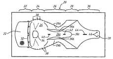
- FIG. 1is a developed plan view of an embodiment of an improved wrap
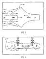
- FIG. 2is a plan view of a cutting template for the wrap shown in FIG. 1 atop a piece of wrap material;
- FIG. 3is an enlarged detail view of the pull tab end of the wrap shown in FIG. 1 prior to adhesive bonding;
- FIG. 4is a plan view of an adhesive template atop the cut piece of fabric used to form the wrap shown in FIG. 1 ;
- FIG. 5is a perspective view of the wrap of FIG. 1 with one end undergoing gluing and clamping;
- FIG. 6is a plan view of the wrap shown in FIG. 1 upon removal from an adhesive clamp
- FIG. 7is a partial detail view of the wrap shown in FIG. 1 beneath an adhesive template
- FIG. 8is an enlarged detailed view of the wrap/template shown in FIG. 7 gluing operation
- FIG. 9is a plan view of the wrap/template shown in FIG. 8 subsequent to the gluing operation
- FIG. 10shows the wrap of FIG. 9 being clamped after the gluing operation
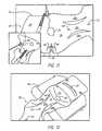
- FIG. 11shows two views of the wrap of FIG. 1 during suturing adjacent to fluid inlet/outlet port opening
- FIG. 12shows the wrap of FIG. 11 positioned in a clamp prior to a heat setting operation
- FIG. 13shows the wrap of FIG. 12 with adhesion locations highlighted
- FIG. 14shows the wrap of FIG. 13 after the gluing operation and adjacent the male part of an adhesive clamp
- FIG. 15shows the wrap of FIG. 14 during a clamping operation adjacent the fluid inlet/outlet port opening.
- FIG. 1there is shown an embodiment of an improved wrap 20 for use with, for example, a heart assist device of the type shown in the actuator PCT application.
- the wrap 20is formed from an elongate piece of woven polyester, or similar non-absorbable, bio-stable and bio-compatible material.
- the wrap 20when developed or extended along its longitudinal direction (as shown), is not substantially planar but instead includes three dimensional portions which will be described in more detail below.
- the wrap 20is generally comprised of five portions namely: a relatively wide suture tab 22 ; a relatively wide domed portion 24 ; a relatively narrow slotted portion 26 ; a relatively wide planar section 28 ; and a pull tab 30 .
- the planar section 28also acts as a suture tab as it mates with the tab 22 after encircling the vessel, which will be described in more detail below.
- the suture tab 22includes a buckle 32 at its proximal end.
- the buckle 32is of the type shown in the Applicant's International PCT Patent Application No. PCT/AU2004/001488 (WO 2005/041781), hereafter “the buckle PCT application”.
- the buckle 32receives the pull tab 30 therethrough during the implantation of a heart assist device, as is described in the buckle PCT application.
- the relevant contents of the buckle PCT applicationare incorporated herein by cross reference.
- the domed surface 24curves outwardly away from that plane.
- the domed surface 24has a generally ovular cross-sectional shape and an inlet/outlet port opening 34 at its apex or geometric centre.
- the domed surface 24tapers outwardly away from the opening 34 to the remainder of the wrap 20 .
- the fluid inlet/outlet tube of an actuatoris positioned through the opening 34 prior to implantation of a heart assist device.
- the domed shape of the surface 24substantially corresponds to the exterior shape of an inflated balloon/chamber type actuator, when implanted on an arterial vessel.
- the domed surface 24also has a curvature to fit the secondary radius of the aorta. The steps included in forming of the domed surface 24 will be described in more detail below.
- the portion 26includes a pair of longitudinally extending curved openings or slits 36 a and 36 b , similar to the slits 32 shown in the wrap PCT application.
- the slits 36 a and 36 bdivide the portion 26 into three parts or strips, namely: two outer strips 26 a and 26 b , which are between the side of the wrap 20 and each of the slits 36 a and 36 b ; and also a central strip 26 c which is between the slits 36 a and 36 b .
- the laterally outer strips 26 a and 26 bare longer than the central strip 26 c .
- the central strip 26 clies substantially in that plane, whereas the laterally outer strips 26 a and 26 b , being longer, project out of that plane. If the material of the wrap is is relatively stiff the outer strips 26 a and 26 b will curve upwardly out of the plane. If the material is softer and more flexible then the projection out of the plane will be more in the nature of crumpling of the material above the plane. Further, the laterally outer edges of the outer strips 26 a and 26 b curve, intermediate their ends, more upwardly out of that plane than the laterally inner edges of the outer strips 26 a and 26 b .
- the longitudinal axes of the strips 26 a and 26 bdiverge from one another, and from the central strip 26 c , as they extend from the central portion 26 (relatively narrow) to the planar portion 28 and domed portion 24 .
- the strips 26 a and 26 bare longer than the strips 26 c in the longitudinal direction of the wrap 20 .
- a curved arterial vessele.g. an ascending aorta
- the strips 26 a , 26 b and 26 cgather together in a manner substantially conforming to the adjacent surface of the vessel without kinking or folding.
- the strips 26 a , 26 b and 26 cconform to the adjacent surfaces of the vessel more closely than the equivalent components of the wrap disclosed in the wrap PCT application, which all had a corresponding length in the longitudinal direction of the wrap.
- the different lengths of the strips 26 a , 26 b and 26 calso allows for the maintenance of the same elastic properties at each location normal to the longitudinal axis of the vessel.
- the manufacture of the outer strips 26 a and 26 bshall be described in more detail below.
- the pull tab 30is formed from two layers of the wrap material, as opposed to the one layer that forms the remainder of the wrap 20 , in order to increase its rigidity. This makes the pull tab 30 easier to handle and position by a surgeon during implantation of a heart assist device.
- the external edges or sides of the portions 24 and 26include a series of spaced apart slits 38 .
- the slits 38result in those parts of the sides of the wrap 20 being more elastic or stretchable than the intermediate central portion of the wrap 20 .
- less tensionis placed in the sides or edges of the wrap 20 than in the centre. This avoids the depression/kinking, and associated high strain levels, associated with earlier wraps, as is discussed in the wrap PCT application.
- the wrap 20also includes two small slots 40 and 42 and a large slot 44 .
- the slots 40 , 42 and 44are used as location points during the manufacture of the wrap, as will be discussed in more detail below. Slot 44 is used for allis clamps or forceps during implant to allow the wrap to be tensioned using standard length surgical instruments.
- the slots 40 and 42also provide areas to enable revascularization or improved blood supply under the wrap 20 when implanted.
- the wrap 20also includes one, two or three size identification markings, in the form of one or more dots 46 adjacent the pull tab 30 .
- One dotindicates a ‘small’ size wrap.
- Two dotsindicate a ‘medium’ size wrap.
- Three dotsindicate a ‘large’ size wrap.
- the manufacture of the wrap 20shall now be described with reference to FIGS. 2 to 15 . All steps in the manufacture of the wrap 20 are performed in a controlled environment room (CER) with all of the operator's material and tools being cleaned to applicable standards.
- CERcontrolled environment room
- FIG. 2shows a stainless steel cutting template 50 adjacent a piece of wrap material 52 .
- the first stage in the production of the wrap 20is to iron the wrap material 52 .
- the ironingis conducted at a linen/dry heat setting.
- the material 52 in the template's five central openings 54 a , 54 b 54 c , 54 d (2 of)is then cut and removed in order to form the openings 34 , 40 , 42 and 44 respectively.
- the material 52 exterior to the wrap template 50is then cut and removed.
- the material 52is cut on its bias, at 45 degrees to the warp/weft of the fabric weave.
- the C shaped cut out 30 c between the tail ends 30 bensures only a single layer of material is in the suturing region. This single layer also reduces the stiffness of the wrap when conforming to the aorta.
- the right hand end of the wrap material 52is folded over itself to align the two openings 54 d that form the large slot 44 in order to form the pull tab 30 .
- the fold at the distal end of the pull tab 30is then ironed with tail ends 30 b aligned with the ends of the slits 36 to create a smooth transition between these parts.
- This foldingalso provides a portion for attaching the adjacent ends of the strips 26 a and 26 b , as will be described in more detail below, whilst also conveniently permitting the wrap 20 to be produced from a single piece of material.
- the folded wrap material 52is then positioned under an adhesive template 56 .
- the template 56includes alignment holes 58 and 60 .
- the alignment hole 58is aligned with the small slot 40 .
- the alignment hole 60is aligned with the size identification markings 46 .
- the holes 58 , 60thus provide references to enable the wrap material to be accurately positioned in relation to the template 56 and ensure the correct size template is used.
- the exposed edge of the wrap material 52is then traced with adhesive in the three locations indicated by arrows 62 .
- the template 62is then removed and the wrap material 52 is folded to the position shown in FIG. 3 and clamped under a load 64 , as shown in FIG. 5 , until the adhesive cures.
- the load 64is then removed leaving the wrap material 52 shown in FIG. 6 .
- FIG. 7shows the wrap material of FIG. 6 clamped beneath an adhesive template 66 (with the strips 26 a and 26 b folded out of the way towards the suture tab 22 ).
- the template 66is aligned with the wrap material 52 at the three locations indicated by arrows 68 .
- Adhesiveis then applied along the exposed edges 70 of the pull tab 30 .
- the outer strips 26 a and 26 bthen have their edges 72 positioned in contact with the adhesive 70 .
- the edge 72is attached to the wrap material closer to the pull tab end of the wrap 20 compared to from where it was cut and on a 30 deg angle from it's original cut edge.
- This longitudinal repositioningresults in the outer strips 26 a and 26 b , intermediate their ends, curving away from the remainder of the wrap 20 when the wrap 20 is positioned on a flat surface.
- the edge 72is also attached more outwardly than compared to from where it was cut.
- This lateral repositioningresults in the laterally outer edges of the outer strips 26 a and 26 b , intermediate their ends, curving away more from the remainder of the wrap 20 than the laterally inner edges of the outer strips 26 a and 26 b .
- the laterally outer edge of strips 26 a and 26 b when positioned on edge 72provide a straight section 28 with edges parallel to the central longitudinal axis of the wrap 20 providing suture region adjustable for within a defined range of vessel diameters
- an additional clamping template 74is then positioned over the overlapping surfaces 70 and 72 being glued together.
- a load 76(similar to the load 64 ) is then applied to the clamped surfaces until the adhesive has cured.
- the wrap material 52has a substantially triangular section removed at 78 either side of the opening 34 .
- the edges 80 and 82 either side of the removed sectionare then overlapped, to form a slot at the edge, and initially held in this position by a suture 84 passing through location 86 and 88 .
- a similar procedureis performed on the opposite side of the wrap material 52 . This forms the basis for producing the domed surface 24 .
- the sutured wrap material 52is then positioned within a mould 90 with an outwardly concave or female recess with an arc on its main axis corresponding in shape an inflated actuator for a heart assist device.
- the wrap material 52 adjacent the domed surface 24is then heat shaped by applying a male outwardly convex dome to apply heat consistently across the surface, adding folds in the correct location and heat shaping the remainder.
- the heatis provided by an iron applied to the mould parts whilst they are clamped together.
- the ironingis conducted at a linen/dry heat setting for approximately 20 to 30 seconds.
- the overlapped material and the deformation caused by the moulding and the iron's heatproduces the smooth domed surface 24 .
- the sutures 84are then removed and the overlapped parts of the wrap material 52 are separated so that adhesive can be applied where indicated by arrows 92 .
- the previously overlapped parts of the wrap material 52are then repositioned in contact with one another and placed over a male mould part 94 .
- a corresponding female mould part 96is then used to clamp the overlapping surfaces until the adhesive cures.
- the wrap 20 formed by the above processwill, when implanted encircling the balloon or chamber of a heart assist device and a curved arterial vessel (eg. the ascending aorta) at a tension lower than would substantially deform the vessel, will substantially conform to the adjacent exterior surfaces of the balloon, chamber and arterial vessel that are in contact with the wrap. More particularly, the wrap 20 will substantially conform to the exterior surface of the balloon, chamber and arterial vessel substantially without wrinkles or folds, whereby the application of force from actuation of the balloon/chamber will be effectively translated normal to the axis of the vessel at any location along the vessel.
- a curved arterial vesseleg. the ascending aorta
Landscapes
- Health & Medical Sciences (AREA)
- Heart & Thoracic Surgery (AREA)
- Engineering & Computer Science (AREA)
- Cardiology (AREA)
- Life Sciences & Earth Sciences (AREA)
- Veterinary Medicine (AREA)
- General Health & Medical Sciences (AREA)
- Biomedical Technology (AREA)
- Public Health (AREA)
- Animal Behavior & Ethology (AREA)
- Anesthesiology (AREA)
- Mechanical Engineering (AREA)
- Hematology (AREA)
- Vascular Medicine (AREA)
- Surgery (AREA)
- Molecular Biology (AREA)
- Nuclear Medicine, Radiotherapy & Molecular Imaging (AREA)
- Medical Informatics (AREA)
- Prostheses (AREA)
Abstract
Description
Claims (11)
Applications Claiming Priority (3)
| Application Number | Priority Date | Filing Date | Title |
|---|---|---|---|
| AU2006904548 | 2006-08-21 | ||
| AU2006904548AAU2006904548A0 (en) | 2006-08-21 | An improved wrap for a heart assist device | |
| PCT/AU2007/001188WO2008022379A1 (en) | 2006-08-21 | 2007-08-20 | An improved wrap for a heart assist device |
Publications (2)
| Publication Number | Publication Date |
|---|---|
| US20100292528A1 US20100292528A1 (en) | 2010-11-18 |
| US8206278B2true US8206278B2 (en) | 2012-06-26 |
Family
ID=39106377
Family Applications (1)
| Application Number | Title | Priority Date | Filing Date |
|---|---|---|---|
| US12/438,105Expired - Fee RelatedUS8206278B2 (en) | 2006-08-21 | 2007-08-20 | Wrap for a heart assist device |
Country Status (4)
| Country | Link |
|---|---|
| US (1) | US8206278B2 (en) |
| EP (1) | EP2054103B1 (en) |
| ES (1) | ES2732090T3 (en) |
| WO (1) | WO2008022379A1 (en) |
Cited By (3)
| Publication number | Priority date | Publication date | Assignee | Title |
|---|---|---|---|---|
| WO2016176431A1 (en)* | 2015-04-29 | 2016-11-03 | The Texas A&M University System | Fully implantable direct cardiac and aortic compression device |
| US10413649B2 (en) | 2014-10-01 | 2019-09-17 | Heartware, Inc. | Back up controller system with updating |
| US12246171B2 (en) | 2021-05-03 | 2025-03-11 | Cardiacbooster B.V. | Cardiac assist device with high frequency operation |
Families Citing this family (10)
| Publication number | Priority date | Publication date | Assignee | Title |
|---|---|---|---|---|
| AUPQ090499A0 (en) | 1999-06-10 | 1999-07-01 | Peters, William S | Heart assist device and system |
| AUPR669001A0 (en)* | 2001-07-30 | 2001-08-23 | Sunshine Heart Company Pty Ltd | A fluid pressure generating means |
| AU2002952691A0 (en) | 2002-11-15 | 2002-11-28 | Sunshine Heart Company Pty Ltd | Heart assist device utilising aortic deformation |
| GB2423028B (en) | 2003-10-30 | 2007-12-19 | Sunshine Heart Co Pty Ltd | A wrap |
| US7887478B2 (en) | 2003-10-31 | 2011-02-15 | Sunshine Heart Company Pty Ltd | Percutaneous gas-line |
| US7765003B2 (en) | 2003-10-31 | 2010-07-27 | Sunshine Heart Pty Ltd | Synchronization control system |
| AU2004286722B2 (en) | 2003-11-11 | 2011-03-03 | Sunshine Heart Company Pty Ltd | Actuator for a heart assist device |
| US20110270331A1 (en) | 2010-04-02 | 2011-11-03 | Sunshine Heart Company Pty Ltd | Combination heart assist systems, methods, and devices |
| ITTO20110504A1 (en)* | 2011-06-08 | 2012-12-09 | Bridgestone Corp | METHOD FOR THE CREATION OF COLORED PORTIONS ON A TIRE |
| WO2015171769A1 (en)* | 2014-05-06 | 2015-11-12 | Sunshine Heart Company Pty, Ltd. | Improved wrap and related systems and methods |
Citations (118)
| Publication number | Priority date | Publication date | Assignee | Title |
|---|---|---|---|---|
| US283660A (en) | 1883-08-21 | Compression-cock | ||
| US929571A (en) | 1908-09-19 | 1909-07-27 | Dubied & Cie Sa E | Valve for pneumatic tires. |
| US1576397A (en) | 1925-07-18 | 1926-03-09 | Yanagi Tokujiro | Tourniquet |
| US1719316A (en) | 1927-03-25 | 1929-07-02 | Central Valve Mfg Co | Valve |
| DE1541311A1 (en) | 1965-11-24 | 1969-09-11 | Zacouto Dr Med Fred | A device which can at least partially be implanted in the organisms to compensate for a heart failure in higher mammals |
| US3467077A (en) | 1966-06-30 | 1969-09-16 | Dupaco Inc | Sphygmomanometric cuff |
| US3552383A (en) | 1969-01-08 | 1971-01-05 | Ibm | Method and system for estimation of arterial pressure |
| US3597766A (en) | 1968-07-11 | 1971-08-10 | Atomic Energy Commission | Artificial heart pumping system powered by a modified stirling cycle engine-compressor having a freely reciprocable displacer piston |
| US4014318A (en) | 1973-08-20 | 1977-03-29 | Dockum James M | Circulatory assist device and system |
| US4051840A (en) | 1976-01-05 | 1977-10-04 | Sinai Hospital Of Detroit | Dynamic aortic patch |
| US4176411A (en) | 1977-11-28 | 1979-12-04 | Runge Thomas M | Cardiac assist device employing electrically stimulated artificial muscle |
| US4195623A (en) | 1977-07-21 | 1980-04-01 | Phillips Steven J | Parallel aorta balloon pump and method of using same |
| US4236482A (en) | 1978-06-09 | 1980-12-02 | Champion International Corporation | Apparatus for applying sealing material to envelopes |
| FR2458288A1 (en) | 1979-06-11 | 1981-01-02 | Belenger Jacques | Cardiac pump with pulsed action - has microprocessor controlled stepping motor acting via screw mechanism on pump diaphragm |
| US4256094A (en) | 1979-06-18 | 1981-03-17 | Kapp John P | Arterial pressure control system |
| US4277706A (en) | 1979-04-16 | 1981-07-07 | Nu-Tech Industries, Inc. | Actuator for heart pump |
| US4304225A (en) | 1979-04-30 | 1981-12-08 | Lloyd And Associates | Control system for body organs |
| US4454891A (en) | 1982-03-09 | 1984-06-19 | Emerson Electric Co. (H & H Precision Products Division) | Air gap drain module for use in a reverse osmosis system |
| US4457673A (en) | 1980-11-28 | 1984-07-03 | Novacor Medical Corporation | Pump and actuator mechanism |
| US4459977A (en) | 1981-03-27 | 1984-07-17 | Veronique Pizon | Coronary sinus retroperfusion apparatus for the treatment of myocardial ischemia |
| US4515587A (en) | 1983-02-14 | 1985-05-07 | Smec, Inc. | IAB having apparatus for assuring proper balloon inflation and deflation |
| US4583523A (en) | 1984-07-02 | 1986-04-22 | Lloyd & Associates | Implantable heart assist device and method of implanting same |
| US4594731A (en) | 1984-11-09 | 1986-06-10 | University Of Utah | Electronic stethoscope |
| US4630597A (en) | 1984-04-30 | 1986-12-23 | Adrian Kantrowitz | Dynamic aortic patch for thoracic or abdominal implantation |
| US4676482A (en) | 1986-04-28 | 1987-06-30 | Rexnord Inc. | Valve seat insert |
| US4697574A (en) | 1985-02-20 | 1987-10-06 | Medicorp Research Laboratories Corp. | Pump for assistance in circulation |
| US4763646A (en) | 1985-10-04 | 1988-08-16 | Siemens Aktiengesellschaft | Heart pacemaker |
| US4771765A (en) | 1984-02-21 | 1988-09-20 | Choy Daniel S J | Heart assist device and method of use |
| US4809676A (en) | 1987-12-28 | 1989-03-07 | Freeman Maynard L | Heart assist device and method of implanting it |
| US4813952A (en) | 1985-08-01 | 1989-03-21 | Medtronic, Inc. | Cardiac assist device |
| US4822357A (en) | 1987-04-29 | 1989-04-18 | Articor Limited | Auxiliary artificial heart |
| US4881939A (en) | 1985-02-19 | 1989-11-21 | The Johns Hopkins University | Implantable helical cuff |
| US4886490A (en)* | 1984-05-14 | 1989-12-12 | Surgical Systems & Instruments, Inc. | Atherectomy catheter system and method of using the same |
| EP0363203A2 (en) | 1988-10-05 | 1990-04-11 | Abiomed, Inc. | Cardiac assist balloon and method of insertion |
| US4957477A (en) | 1986-05-22 | 1990-09-18 | Astra Tech Ab | Heart assist jacket and method of using it |
| FR2645739A1 (en) | 1989-04-14 | 1990-10-19 | Vm Tech Sa | Cardiac assistance device and its use |
| US4979936A (en) | 1987-04-28 | 1990-12-25 | Trustees Of The University Of Pennsylvania | Autologous biologic pump motor |
| WO1990015630A1 (en) | 1989-06-20 | 1990-12-27 | Sphinx Medical Limited | Improving blood flow |
| EP0216042B1 (en) | 1985-08-01 | 1991-03-06 | Medtronic, Inc. | Cardiac assist device |
| US5089017A (en) | 1989-01-17 | 1992-02-18 | Young David B | Drive system for artificial hearts and left-ventricular assist devices |
| US5169378A (en) | 1990-07-20 | 1992-12-08 | Diego Figuera | Intra-ventricular expansible assist pump |
| US5197980A (en) | 1990-08-14 | 1993-03-30 | Gorshkov Jury V | Cardiac valve prosthesis |
| US5205810A (en) | 1990-10-15 | 1993-04-27 | Medtronic, Inc. | Muscle powered cardiac assist system |
| US5222980A (en) | 1991-09-27 | 1993-06-29 | Medtronic, Inc. | Implantable heart-assist device |
| US5267940A (en) | 1989-11-29 | 1993-12-07 | The Administrators Of The Tulane Educational Fund | Cardiovascular flow enhancer and method of operation |
| US5273518A (en) | 1992-01-31 | 1993-12-28 | Medtronic, Inc. | Cardiac assist apparatus |
| US5290249A (en) | 1990-10-09 | 1994-03-01 | Vance Products Incorporated | Surgical access sheath |
| US5300111A (en) | 1992-02-03 | 1994-04-05 | Pyxis, Inc. | Total artificial heart |
| EP0601804A1 (en) | 1992-12-07 | 1994-06-15 | SMITH & NEPHEW RICHARDS, INC. | Medical implants of biocompatible low modulus titanium alloy |
| US5337752A (en) | 1992-05-21 | 1994-08-16 | Mcg International, Inc. | System for simultaneously producing and synchronizing spectral patterns of heart sounds and an ECG signal |
| US5344385A (en) | 1991-09-30 | 1994-09-06 | Thoratec Laboratories Corporation | Step-down skeletal muscle energy conversion system |
| EP0080348B2 (en) | 1981-11-19 | 1994-09-07 | Medtronic, Inc. | Rate adaptive pacer |
| US5360445A (en) | 1991-11-06 | 1994-11-01 | International Business Machines Corporation | Blood pump actuator |
| EP0364799B1 (en) | 1988-10-21 | 1995-05-03 | Delcath Systems, Inc. | Cancer treatment |
| US5429584A (en) | 1990-11-09 | 1995-07-04 | Mcgill University | Cardiac assist method and apparatus |
| US5447523A (en) | 1985-02-22 | 1995-09-05 | Biotronik Mess-Und Therapiegerate Gmbh & Co. | Pacemaker with physiological control of stimulation |
| US5453076A (en) | 1992-04-17 | 1995-09-26 | Kiyota; Yoshiharu | Internal cardiac assist apparatus |
| US5511551A (en) | 1993-03-15 | 1996-04-30 | Omron Corporation | Cuff for blood pressure meter |
| US5554177A (en) | 1995-03-27 | 1996-09-10 | Medtronic, Inc. | Method and apparatus to optimize pacing based on intensity of acoustic signal |
| US5569156A (en) | 1993-09-10 | 1996-10-29 | Ottawa Heart Institute Research Corporation | Electrohydraulic ventricular assist device |
| US5593414A (en) | 1993-08-25 | 1997-01-14 | Apollo Camera, L.L.C. | Method of applying a surgical ligation clip |
| US5607378A (en) | 1994-11-21 | 1997-03-04 | Winston; Edith | Method of exercising a selected muscle |
| US5647380A (en) | 1995-06-07 | 1997-07-15 | W. L. Gore & Associates, Inc. | Method of making a left ventricular assist device |
| US5722930A (en) | 1992-08-06 | 1998-03-03 | Electric Boat Corporation | Reciprocating pump circulatory assist arrangement |
| US5792195A (en) | 1996-12-16 | 1998-08-11 | Cardiac Pacemakers, Inc. | Acceleration sensed safe upper rate envelope for calculating the hemodynamic upper rate limit for a rate adaptive cardiac rhythm management device |
| US5814012A (en) | 1992-03-16 | 1998-09-29 | Birtcher Medical Systems, Inc. | Method and apparatus for relieving excess insufflation pressure |
| US5820542A (en) | 1996-10-31 | 1998-10-13 | Momentum Medical, Inc. | Modified circulatory assist device |
| US5827171A (en) | 1996-10-31 | 1998-10-27 | Momentum Medical, Inc. | Intravascular circulatory assist device |
| US5843170A (en) | 1994-09-02 | 1998-12-01 | Ahn; Sam Seunghae | Apparatus and method for performing aneurysm repair |
| FR2767874A1 (en) | 1997-08-26 | 1999-02-26 | Commissariat Energie Atomique | Fluid actuator for implantable cardiac assist operating in counter pulse mode. |
| JPH11285529A (en) | 1998-01-28 | 1999-10-19 | Vascor Inc | Single room blood pump apparatus |
| US5975140A (en) | 1997-07-28 | 1999-11-02 | Lin; Ching-Yi | Gooseneck faucet |
| US5980488A (en) | 1995-01-10 | 1999-11-09 | Specialized Health Products, Inc. | Medical needle safety apparatus and methods |
| JP2000000299A (en) | 1998-04-13 | 2000-01-07 | Jms Co Ltd | Extracorporeal circulation apparatus having control function |
| US6030336A (en) | 1996-02-21 | 2000-02-29 | Synthelabo Biomedical (Societe Anonyme) | Pressure generator for a counterpressure cardiac assistance device |
| US6045496A (en) | 1994-04-15 | 2000-04-04 | Allegheny-Singer Research Institute | Occluder device and method of making |
| JP2000510006A (en) | 1996-04-29 | 2000-08-08 | ダブリュ.エル.ゴア アンド アソシエイツ,インコーポレイティド | Venous valve capacity recovery device |
| US6132636A (en) | 1998-10-23 | 2000-10-17 | Allied Signal Inc | Leak-detecting refrigerant compositions containing oxazolyl-coumarin dyes |
| US6132363A (en) | 1997-09-30 | 2000-10-17 | L.Vad Technology, Inc. | Cardiovascular support control system |
| US6210318B1 (en) | 1999-03-09 | 2001-04-03 | Abiomed, Inc. | Stented balloon pump system and method for using same |
| US6210319B1 (en) | 1999-04-21 | 2001-04-03 | Datascope Investment Corp. | Intra-aortic balloon pump condensation prevention system |
| US6226843B1 (en) | 1999-02-25 | 2001-05-08 | Design Standards Corporation | Ligating clip |
| US6251061B1 (en) | 1998-09-09 | 2001-06-26 | Scimed Life Systems, Inc. | Cardiac assist device using field controlled fluid |
| US20010016676A1 (en) | 1999-04-21 | 2001-08-23 | Jonathan Williams | Intra-aortic balloon pump condensation prevention system |
| EP1129736A1 (en) | 2000-03-02 | 2001-09-05 | Levram Medical Devices, Ltd. | Ventricular-assist method and apparatus |
| US6432039B1 (en) | 1998-12-21 | 2002-08-13 | Corset, Inc. | Methods and apparatus for reinforcement of the heart ventricles |
| US6471633B1 (en) | 1999-08-23 | 2002-10-29 | L.Vad Technology, Inc. | Mechanical auxillary ventricle blood pump with reduced waist portion |
| US6553263B1 (en) | 1999-07-30 | 2003-04-22 | Advanced Bionics Corporation | Implantable pulse generators using rechargeable zero-volt technology lithium-ion batteries |
| JP2003135497A (en) | 2001-11-06 | 2003-05-13 | Miwatec:Kk | Percutaneous information transmission system for artificial organs. |
| US6572534B1 (en) | 2000-09-14 | 2003-06-03 | Abiomed, Inc. | System and method for implanting a cardiac wrap |
| US20030105497A1 (en) | 2001-12-03 | 2003-06-05 | Cardiac Pacemakers, Inc. | Implantable cardiac disease management device with trigger-stored polysomnogram and phonocardiogram |
| US6585635B1 (en) | 1999-09-17 | 2003-07-01 | Core Medical, Inc. | Method and system for pericardial modification |
| US6616596B1 (en) | 2000-11-28 | 2003-09-09 | Abiomed, Inc. | Cardiac assistance systems having multiple layers of inflatable elements |
| US6626821B1 (en) | 2001-05-22 | 2003-09-30 | Abiomed, Inc. | Flow-balanced cardiac wrap |
| US6643548B1 (en) | 2000-04-06 | 2003-11-04 | Pacesetter, Inc. | Implantable cardiac stimulation device for monitoring heart sounds to detect progression and regression of heart disease and method thereof |
| US20040010180A1 (en) | 2002-05-16 | 2004-01-15 | Scorvo Sean K. | Cardiac assist system |
| US20040073080A1 (en) | 2000-09-22 | 2004-04-15 | Peters William Suttle | Heart assist devices, systems and methods |
| US20040097784A1 (en) | 2002-11-15 | 2004-05-20 | Sunshine Heart Company Pty Ltd. | Intraluminal inflatable counter-pulsation heart assist device |
| US20040097783A1 (en) | 2002-11-15 | 2004-05-20 | Peters William Suttle | Heart assist device utilising aortic deformation |
| US20040147803A1 (en) | 2002-10-07 | 2004-07-29 | Hegde Anant V. | Vascular assist device and methods |
| US20040152945A1 (en) | 2003-01-31 | 2004-08-05 | Adrian Kantrowitz | Stable aortic blood pump implant |
| US6808483B1 (en) | 2000-10-03 | 2004-10-26 | Paul A. Spence | Implantable heart assist devices and methods |
| US6808484B1 (en) | 1999-06-10 | 2004-10-26 | Sunshine Heart Company Pty Ltd | Heart assist devices, systems and methods |
| WO2005041783A1 (en) | 2003-10-30 | 2005-05-12 | Sunshine Heart Company Pty Ltd | A wrap |
| WO2005110512A1 (en) | 2004-05-11 | 2005-11-24 | Ppa Technologies Ag | Device for epicardial support and/or resumption of cardiac activity |
| US6984201B2 (en) | 2000-09-23 | 2006-01-10 | Harefield Cardiac Limited | Blood circulation assistance device |
| US20060052866A1 (en) | 2002-12-19 | 2006-03-09 | Unisearch Limited | Method of treating a stiffened blood vessel |
| US20070021830A1 (en) | 2003-10-31 | 2007-01-25 | Peters William S | Percutaneous gas-line |
| US7169109B2 (en) | 2000-10-03 | 2007-01-30 | Arrow International, Inc. | Methods and apparatus for controlling heart assist devices |
| US20070093684A1 (en) | 2003-10-30 | 2007-04-26 | Sunshine Heart Company Pty Ltd. | Extra-aortic patch |
| US20070129796A1 (en) | 2003-11-11 | 2007-06-07 | Miller Scott H | Actuator for a heart assist device |
| US20070167898A1 (en) | 2003-10-30 | 2007-07-19 | Sunshine Heart Company Pty Ltd. | Methods and devices for tensioning a wrap around a blood vessel |
| US7306558B2 (en) | 2001-07-30 | 2007-12-11 | Sunshine Heart Company Pty Ltd. | Fluid pressure generating means |
| AU2003277983B2 (en) | 2002-11-15 | 2008-06-26 | Sunshine Heart Company Pty Ltd | Heart assist device utilising aortic deformation |
| US20080194905A1 (en) | 2004-03-02 | 2008-08-14 | Peter William Walsh | Vessel or Sac Wall Treatment and a Cardiac Assist Device |
| US7513864B2 (en) | 2004-07-09 | 2009-04-07 | Kantrowitz Allen B | Synchronization system between aortic valve and cardiac assist device |
| US7766049B2 (en) | 2001-06-26 | 2010-08-03 | Concentric Medical, Inc. | Balloon catheter |
| US20110270331A1 (en) | 2010-04-02 | 2011-11-03 | Sunshine Heart Company Pty Ltd | Combination heart assist systems, methods, and devices |
- 2007
- 2007-08-20USUS12/438,105patent/US8206278B2/ennot_activeExpired - Fee Related
- 2007-08-20ESES07784826Tpatent/ES2732090T3/enactiveActive
- 2007-08-20EPEP07784826.5Apatent/EP2054103B1/ennot_activeNot-in-force
- 2007-08-20WOPCT/AU2007/001188patent/WO2008022379A1/enactiveApplication Filing
Patent Citations (131)
| Publication number | Priority date | Publication date | Assignee | Title |
|---|---|---|---|---|
| US283660A (en) | 1883-08-21 | Compression-cock | ||
| US929571A (en) | 1908-09-19 | 1909-07-27 | Dubied & Cie Sa E | Valve for pneumatic tires. |
| US1576397A (en) | 1925-07-18 | 1926-03-09 | Yanagi Tokujiro | Tourniquet |
| US1719316A (en) | 1927-03-25 | 1929-07-02 | Central Valve Mfg Co | Valve |
| DE1541311A1 (en) | 1965-11-24 | 1969-09-11 | Zacouto Dr Med Fred | A device which can at least partially be implanted in the organisms to compensate for a heart failure in higher mammals |
| US3467077A (en) | 1966-06-30 | 1969-09-16 | Dupaco Inc | Sphygmomanometric cuff |
| US3597766A (en) | 1968-07-11 | 1971-08-10 | Atomic Energy Commission | Artificial heart pumping system powered by a modified stirling cycle engine-compressor having a freely reciprocable displacer piston |
| US3552383A (en) | 1969-01-08 | 1971-01-05 | Ibm | Method and system for estimation of arterial pressure |
| US4014318A (en) | 1973-08-20 | 1977-03-29 | Dockum James M | Circulatory assist device and system |
| US4051840A (en) | 1976-01-05 | 1977-10-04 | Sinai Hospital Of Detroit | Dynamic aortic patch |
| US4195623A (en) | 1977-07-21 | 1980-04-01 | Phillips Steven J | Parallel aorta balloon pump and method of using same |
| US4176411A (en) | 1977-11-28 | 1979-12-04 | Runge Thomas M | Cardiac assist device employing electrically stimulated artificial muscle |
| US4236482A (en) | 1978-06-09 | 1980-12-02 | Champion International Corporation | Apparatus for applying sealing material to envelopes |
| US4277706A (en) | 1979-04-16 | 1981-07-07 | Nu-Tech Industries, Inc. | Actuator for heart pump |
| US4304225A (en) | 1979-04-30 | 1981-12-08 | Lloyd And Associates | Control system for body organs |
| FR2458288A1 (en) | 1979-06-11 | 1981-01-02 | Belenger Jacques | Cardiac pump with pulsed action - has microprocessor controlled stepping motor acting via screw mechanism on pump diaphragm |
| US4256094A (en) | 1979-06-18 | 1981-03-17 | Kapp John P | Arterial pressure control system |
| US4457673A (en) | 1980-11-28 | 1984-07-03 | Novacor Medical Corporation | Pump and actuator mechanism |
| US4459977A (en) | 1981-03-27 | 1984-07-17 | Veronique Pizon | Coronary sinus retroperfusion apparatus for the treatment of myocardial ischemia |
| EP0080348B2 (en) | 1981-11-19 | 1994-09-07 | Medtronic, Inc. | Rate adaptive pacer |
| US4454891A (en) | 1982-03-09 | 1984-06-19 | Emerson Electric Co. (H & H Precision Products Division) | Air gap drain module for use in a reverse osmosis system |
| US4515587A (en) | 1983-02-14 | 1985-05-07 | Smec, Inc. | IAB having apparatus for assuring proper balloon inflation and deflation |
| US4771765A (en) | 1984-02-21 | 1988-09-20 | Choy Daniel S J | Heart assist device and method of use |
| US4630597A (en) | 1984-04-30 | 1986-12-23 | Adrian Kantrowitz | Dynamic aortic patch for thoracic or abdominal implantation |
| US4886490A (en)* | 1984-05-14 | 1989-12-12 | Surgical Systems & Instruments, Inc. | Atherectomy catheter system and method of using the same |
| US4583523A (en) | 1984-07-02 | 1986-04-22 | Lloyd & Associates | Implantable heart assist device and method of implanting same |
| US4594731A (en) | 1984-11-09 | 1986-06-10 | University Of Utah | Electronic stethoscope |
| US4881939A (en) | 1985-02-19 | 1989-11-21 | The Johns Hopkins University | Implantable helical cuff |
| US4697574A (en) | 1985-02-20 | 1987-10-06 | Medicorp Research Laboratories Corp. | Pump for assistance in circulation |
| US5447523A (en) | 1985-02-22 | 1995-09-05 | Biotronik Mess-Und Therapiegerate Gmbh & Co. | Pacemaker with physiological control of stimulation |
| EP0216042B1 (en) | 1985-08-01 | 1991-03-06 | Medtronic, Inc. | Cardiac assist device |
| US4813952A (en) | 1985-08-01 | 1989-03-21 | Medtronic, Inc. | Cardiac assist device |
| US4763646A (en) | 1985-10-04 | 1988-08-16 | Siemens Aktiengesellschaft | Heart pacemaker |
| US4676482A (en) | 1986-04-28 | 1987-06-30 | Rexnord Inc. | Valve seat insert |
| US4957477A (en) | 1986-05-22 | 1990-09-18 | Astra Tech Ab | Heart assist jacket and method of using it |
| US4979936A (en) | 1987-04-28 | 1990-12-25 | Trustees Of The University Of Pennsylvania | Autologous biologic pump motor |
| US4822357A (en) | 1987-04-29 | 1989-04-18 | Articor Limited | Auxiliary artificial heart |
| US4809676A (en) | 1987-12-28 | 1989-03-07 | Freeman Maynard L | Heart assist device and method of implanting it |
| EP0363203A2 (en) | 1988-10-05 | 1990-04-11 | Abiomed, Inc. | Cardiac assist balloon and method of insertion |
| EP0364799B1 (en) | 1988-10-21 | 1995-05-03 | Delcath Systems, Inc. | Cancer treatment |
| US5089017A (en) | 1989-01-17 | 1992-02-18 | Young David B | Drive system for artificial hearts and left-ventricular assist devices |
| FR2645739A1 (en) | 1989-04-14 | 1990-10-19 | Vm Tech Sa | Cardiac assistance device and its use |
| WO1990015630A1 (en) | 1989-06-20 | 1990-12-27 | Sphinx Medical Limited | Improving blood flow |
| US5372573A (en) | 1989-06-20 | 1994-12-13 | British Technology Group Limited | Blood flow |
| US5267940A (en) | 1989-11-29 | 1993-12-07 | The Administrators Of The Tulane Educational Fund | Cardiovascular flow enhancer and method of operation |
| US5169378A (en) | 1990-07-20 | 1992-12-08 | Diego Figuera | Intra-ventricular expansible assist pump |
| US5197980A (en) | 1990-08-14 | 1993-03-30 | Gorshkov Jury V | Cardiac valve prosthesis |
| US5290249A (en) | 1990-10-09 | 1994-03-01 | Vance Products Incorporated | Surgical access sheath |
| US5205810A (en) | 1990-10-15 | 1993-04-27 | Medtronic, Inc. | Muscle powered cardiac assist system |
| US5429584A (en) | 1990-11-09 | 1995-07-04 | Mcgill University | Cardiac assist method and apparatus |
| US5222980A (en) | 1991-09-27 | 1993-06-29 | Medtronic, Inc. | Implantable heart-assist device |
| US5344385A (en) | 1991-09-30 | 1994-09-06 | Thoratec Laboratories Corporation | Step-down skeletal muscle energy conversion system |
| US5360445A (en) | 1991-11-06 | 1994-11-01 | International Business Machines Corporation | Blood pump actuator |
| US5273518A (en) | 1992-01-31 | 1993-12-28 | Medtronic, Inc. | Cardiac assist apparatus |
| US5300111A (en) | 1992-02-03 | 1994-04-05 | Pyxis, Inc. | Total artificial heart |
| US5814012A (en) | 1992-03-16 | 1998-09-29 | Birtcher Medical Systems, Inc. | Method and apparatus for relieving excess insufflation pressure |
| US5453076A (en) | 1992-04-17 | 1995-09-26 | Kiyota; Yoshiharu | Internal cardiac assist apparatus |
| US5337752A (en) | 1992-05-21 | 1994-08-16 | Mcg International, Inc. | System for simultaneously producing and synchronizing spectral patterns of heart sounds and an ECG signal |
| US5722930A (en) | 1992-08-06 | 1998-03-03 | Electric Boat Corporation | Reciprocating pump circulatory assist arrangement |
| EP0601804A1 (en) | 1992-12-07 | 1994-06-15 | SMITH & NEPHEW RICHARDS, INC. | Medical implants of biocompatible low modulus titanium alloy |
| US5511551A (en) | 1993-03-15 | 1996-04-30 | Omron Corporation | Cuff for blood pressure meter |
| US5593414A (en) | 1993-08-25 | 1997-01-14 | Apollo Camera, L.L.C. | Method of applying a surgical ligation clip |
| US5569156A (en) | 1993-09-10 | 1996-10-29 | Ottawa Heart Institute Research Corporation | Electrohydraulic ventricular assist device |
| US6045496A (en) | 1994-04-15 | 2000-04-04 | Allegheny-Singer Research Institute | Occluder device and method of making |
| US5843170A (en) | 1994-09-02 | 1998-12-01 | Ahn; Sam Seunghae | Apparatus and method for performing aneurysm repair |
| US5607378A (en) | 1994-11-21 | 1997-03-04 | Winston; Edith | Method of exercising a selected muscle |
| US5980488A (en) | 1995-01-10 | 1999-11-09 | Specialized Health Products, Inc. | Medical needle safety apparatus and methods |
| US5554177A (en) | 1995-03-27 | 1996-09-10 | Medtronic, Inc. | Method and apparatus to optimize pacing based on intensity of acoustic signal |
| US5647380A (en) | 1995-06-07 | 1997-07-15 | W. L. Gore & Associates, Inc. | Method of making a left ventricular assist device |
| US6030336A (en) | 1996-02-21 | 2000-02-29 | Synthelabo Biomedical (Societe Anonyme) | Pressure generator for a counterpressure cardiac assistance device |
| JP2000510006A (en) | 1996-04-29 | 2000-08-08 | ダブリュ.エル.ゴア アンド アソシエイツ,インコーポレイティド | Venous valve capacity recovery device |
| US5820542A (en) | 1996-10-31 | 1998-10-13 | Momentum Medical, Inc. | Modified circulatory assist device |
| US5827171A (en) | 1996-10-31 | 1998-10-27 | Momentum Medical, Inc. | Intravascular circulatory assist device |
| US5792195A (en) | 1996-12-16 | 1998-08-11 | Cardiac Pacemakers, Inc. | Acceleration sensed safe upper rate envelope for calculating the hemodynamic upper rate limit for a rate adaptive cardiac rhythm management device |
| US5975140A (en) | 1997-07-28 | 1999-11-02 | Lin; Ching-Yi | Gooseneck faucet |
| FR2767874A1 (en) | 1997-08-26 | 1999-02-26 | Commissariat Energie Atomique | Fluid actuator for implantable cardiac assist operating in counter pulse mode. |
| US6132363A (en) | 1997-09-30 | 2000-10-17 | L.Vad Technology, Inc. | Cardiovascular support control system |
| JPH11285529A (en) | 1998-01-28 | 1999-10-19 | Vascor Inc | Single room blood pump apparatus |
| US6066085A (en) | 1998-01-28 | 2000-05-23 | Vascor, Inc. | Single chamber blood pump |
| JP2000000299A (en) | 1998-04-13 | 2000-01-07 | Jms Co Ltd | Extracorporeal circulation apparatus having control function |
| US6251061B1 (en) | 1998-09-09 | 2001-06-26 | Scimed Life Systems, Inc. | Cardiac assist device using field controlled fluid |
| US6132636A (en) | 1998-10-23 | 2000-10-17 | Allied Signal Inc | Leak-detecting refrigerant compositions containing oxazolyl-coumarin dyes |
| US6432039B1 (en) | 1998-12-21 | 2002-08-13 | Corset, Inc. | Methods and apparatus for reinforcement of the heart ventricles |
| US6226843B1 (en) | 1999-02-25 | 2001-05-08 | Design Standards Corporation | Ligating clip |
| US6210318B1 (en) | 1999-03-09 | 2001-04-03 | Abiomed, Inc. | Stented balloon pump system and method for using same |
| US20010016676A1 (en) | 1999-04-21 | 2001-08-23 | Jonathan Williams | Intra-aortic balloon pump condensation prevention system |
| US6210319B1 (en) | 1999-04-21 | 2001-04-03 | Datascope Investment Corp. | Intra-aortic balloon pump condensation prevention system |
| US7357771B2 (en) | 1999-06-10 | 2008-04-15 | Sunshine Heart Company Pty Limited | Heart assist devices, systems and methods |
| US6808484B1 (en) | 1999-06-10 | 2004-10-26 | Sunshine Heart Company Pty Ltd | Heart assist devices, systems and methods |
| US20080139873A1 (en) | 1999-06-10 | 2008-06-12 | William Suttle Peters | Heart Assist Devices, Systems and Methods |
| US6553263B1 (en) | 1999-07-30 | 2003-04-22 | Advanced Bionics Corporation | Implantable pulse generators using rechargeable zero-volt technology lithium-ion batteries |
| US6471633B1 (en) | 1999-08-23 | 2002-10-29 | L.Vad Technology, Inc. | Mechanical auxillary ventricle blood pump with reduced waist portion |
| US6585635B1 (en) | 1999-09-17 | 2003-07-01 | Core Medical, Inc. | Method and system for pericardial modification |
| JP2001276213A (en) | 2000-03-02 | 2001-10-09 | Levram Medical Devices Ltd | Ventricular assist method and device |
| US6406422B1 (en) | 2000-03-02 | 2002-06-18 | Levram Medical Devices, Ltd. | Ventricular-assist method and apparatus |
| EP1129736A1 (en) | 2000-03-02 | 2001-09-05 | Levram Medical Devices, Ltd. | Ventricular-assist method and apparatus |
| US6643548B1 (en) | 2000-04-06 | 2003-11-04 | Pacesetter, Inc. | Implantable cardiac stimulation device for monitoring heart sounds to detect progression and regression of heart disease and method thereof |
| US6572534B1 (en) | 2000-09-14 | 2003-06-03 | Abiomed, Inc. | System and method for implanting a cardiac wrap |
| US20040073080A1 (en) | 2000-09-22 | 2004-04-15 | Peters William Suttle | Heart assist devices, systems and methods |
| US6984201B2 (en) | 2000-09-23 | 2006-01-10 | Harefield Cardiac Limited | Blood circulation assistance device |
| US6808483B1 (en) | 2000-10-03 | 2004-10-26 | Paul A. Spence | Implantable heart assist devices and methods |
| US7169109B2 (en) | 2000-10-03 | 2007-01-30 | Arrow International, Inc. | Methods and apparatus for controlling heart assist devices |
| US6616596B1 (en) | 2000-11-28 | 2003-09-09 | Abiomed, Inc. | Cardiac assistance systems having multiple layers of inflatable elements |
| US6626821B1 (en) | 2001-05-22 | 2003-09-30 | Abiomed, Inc. | Flow-balanced cardiac wrap |
| US7766049B2 (en) | 2001-06-26 | 2010-08-03 | Concentric Medical, Inc. | Balloon catheter |
| US7306558B2 (en) | 2001-07-30 | 2007-12-11 | Sunshine Heart Company Pty Ltd. | Fluid pressure generating means |
| US20080027270A1 (en) | 2001-07-30 | 2008-01-31 | Peters William S | Fluid Pressure Generating Means |
| US7740575B2 (en) | 2001-07-30 | 2010-06-22 | Sunshine Heart, Inc. | Fluid pressure generating means |
| JP2003135497A (en) | 2001-11-06 | 2003-05-13 | Miwatec:Kk | Percutaneous information transmission system for artificial organs. |
| US20030105497A1 (en) | 2001-12-03 | 2003-06-05 | Cardiac Pacemakers, Inc. | Implantable cardiac disease management device with trigger-stored polysomnogram and phonocardiogram |
| US20040010180A1 (en) | 2002-05-16 | 2004-01-15 | Scorvo Sean K. | Cardiac assist system |
| US20040147803A1 (en) | 2002-10-07 | 2004-07-29 | Hegde Anant V. | Vascular assist device and methods |
| AU2003277983B2 (en) | 2002-11-15 | 2008-06-26 | Sunshine Heart Company Pty Ltd | Heart assist device utilising aortic deformation |
| US20080167515A1 (en) | 2002-11-15 | 2008-07-10 | William Suttle Peters | Heart Assist Device Utilising Aortic Deformation |
| US7347811B2 (en) | 2002-11-15 | 2008-03-25 | Sunshine Heart Company Pty Ltd. | Heart assist device utilising aortic deformation |
| US20040097783A1 (en) | 2002-11-15 | 2004-05-20 | Peters William Suttle | Heart assist device utilising aortic deformation |
| US20040097784A1 (en) | 2002-11-15 | 2004-05-20 | Sunshine Heart Company Pty Ltd. | Intraluminal inflatable counter-pulsation heart assist device |
| US20060052866A1 (en) | 2002-12-19 | 2006-03-09 | Unisearch Limited | Method of treating a stiffened blood vessel |
| US20040152945A1 (en) | 2003-01-31 | 2004-08-05 | Adrian Kantrowitz | Stable aortic blood pump implant |
| WO2005041783A1 (en) | 2003-10-30 | 2005-05-12 | Sunshine Heart Company Pty Ltd | A wrap |
| US20070167898A1 (en) | 2003-10-30 | 2007-07-19 | Sunshine Heart Company Pty Ltd. | Methods and devices for tensioning a wrap around a blood vessel |
| GB2422114B (en) | 2003-10-30 | 2008-04-16 | Sunshine Heart Co Pty Ltd | Extra-aortic patch |
| US20070135677A1 (en) | 2003-10-30 | 2007-06-14 | Sunshine Heart Company Pty Ltd | Wrap |
| US20070093684A1 (en) | 2003-10-30 | 2007-04-26 | Sunshine Heart Company Pty Ltd. | Extra-aortic patch |
| US20110196467A1 (en) | 2003-10-30 | 2011-08-11 | Sunshine Heart Company Pty Ltd | Blood vessel wrap |
| US20070021830A1 (en) | 2003-10-31 | 2007-01-25 | Peters William S | Percutaneous gas-line |
| US20070129796A1 (en) | 2003-11-11 | 2007-06-07 | Miller Scott H | Actuator for a heart assist device |
| US20080194905A1 (en) | 2004-03-02 | 2008-08-14 | Peter William Walsh | Vessel or Sac Wall Treatment and a Cardiac Assist Device |
| WO2005110512A1 (en) | 2004-05-11 | 2005-11-24 | Ppa Technologies Ag | Device for epicardial support and/or resumption of cardiac activity |
| US7513864B2 (en) | 2004-07-09 | 2009-04-07 | Kantrowitz Allen B | Synchronization system between aortic valve and cardiac assist device |
| US20110270331A1 (en) | 2010-04-02 | 2011-11-03 | Sunshine Heart Company Pty Ltd | Combination heart assist systems, methods, and devices |
Non-Patent Citations (28)
| Title |
|---|
| "Use of Heart Valve Sounds as Input to Cardiac Assist Devices", Research Disclosures, Mar. 1995. |
| Hiroshi Odaguchi et al., "Experimental Study of Extraaortic Balloon Counterpulsation as a Bridge to Other Mechanical Assists" ASAIO Journal, pp. 190-194, vol. 42, No. 3, Lippincott Williams & Wilkins/ASAIO, Hagerstown, MD, May 1, 1996. cited by other. |
| International Preliminary Examination Report issued in PCT/AU2001/01187, completed May 2, 2002, 4 pages. |
| International Preliminary Examination Report issued in PCT/AU2002/000974, completed Aug. 11, 2003, 8 pages. |
| International Preliminary Examination Report issued in PCT/AU2003/001450, completed Mar. 2, 2005, 4 pages. |
| International Preliminary Report on patentability, Chapter II, issued in PCT/AU2007/001188, completed Mar. 11, 2008, 8 pages. |
| International Prelminary Examination Report issued in PCT/AU2003/001458, completed Mar. 7, 2005, 7 pages. |
| International Search Report and Written Opinion issued in PCT/AU2004/001483, mailed Nov. 26, 2004, 5 pages. |
| International Search Report and Written Opinion issued in PCT/AU2004/001484, mailed Nov. 29, 2004, 5 pages. |
| International Search Report and Written Opinion issued in PCT/AU2004/001486, mailed Jan. 6, 2005, 7 pages. |
| International Search Report and Written Opinion issued in PCT/AU2004/01485, mailed Feb. 7, 2005, 6 pages. |
| International Search Report and Written Opinion issued in PCT/AU2004/01487, mailed Jan. 27, 2005, 12 pages. |
| International Search Report and Written Opinion issued in PCT/AU2004/01488, mailed Dec. 15, 2004, 6 pages. |
| International Search Report and Written Opinion issued in PCT/AU2007/001188, mailed Oct. 4, 2007, 12 pages. |
| International Search Report issued in PCT/AU00/00654, mailed Aug. 18, 2000, 5 pages. |
| International Search Report issued in PCT/AU2001/01187, mailed Nov. 5, 2001, 3 pages. |
| International Search Report issued in PCT/AU2002/000974, mailed Oct. 11, 2002, 5 pages. |
| International Search Report issued in PCT/AU2003/001450, mailed Feb. 2, 2004, 2 pages. |
| International Search Report issued in PCT/AU2003/001458, mailed Feb. 5, 2004, 5 pages. |
| J.L. Stewart, "Aortic Cuff a Cardiac Assistance Device", Polytechnic Institute of Brooklyn, 1968, pp. 9-108. |
| Luisada et al., On the Function of the Aortic Valve and the Mechanism of the First and Second Sounds, Japanese Heart Journal, vol. 18(1), Jan. 1977, pp. 81-91. |
| Office Action issued in JP Application No. 2004-552261, dated Mar. 2, 2010. |
| Seymour Furman et al., "Cardiac Support by Periaortic Diastolic Augmentation", New York Journal of Medicine, Aug. 1, 1970, pp. 1964-1969. |
| Supplemental European Search Report issued in EP 01971489, completed Nov. 22, 2006, 4 pages. |
| Supplemental European Search Report issued in EP 04789625, mailed Nov. 18, 2009, 6 pages. |
| Supplemental European Search Report issued in EP App No. 02748447, Feb. 6, 2007, 6 pages. |
| Supplemental European Search Report issued in EP App. No. 04789624, mailed Mar. 6, 2008, 7 pages. |
| Supplemental European Search Report issued in EP Application 00934813, mailed 0/19/2006, 2 pages. |
Cited By (4)
| Publication number | Priority date | Publication date | Assignee | Title |
|---|---|---|---|---|
| US10413649B2 (en) | 2014-10-01 | 2019-09-17 | Heartware, Inc. | Back up controller system with updating |
| WO2016176431A1 (en)* | 2015-04-29 | 2016-11-03 | The Texas A&M University System | Fully implantable direct cardiac and aortic compression device |
| US12246171B2 (en) | 2021-05-03 | 2025-03-11 | Cardiacbooster B.V. | Cardiac assist device with high frequency operation |
| US12420077B2 (en) | 2021-05-03 | 2025-09-23 | Cardiacbooster B.V. | Cardiac assist device with high frequency operation |
Also Published As
| Publication number | Publication date |
|---|---|
| WO2008022379A1 (en) | 2008-02-28 |
| EP2054103B1 (en) | 2019-05-29 |
| ES2732090T3 (en) | 2019-11-20 |
| EP2054103A1 (en) | 2009-05-06 |
| EP2054103A4 (en) | 2018-04-11 |
| US20100292528A1 (en) | 2010-11-18 |
Similar Documents
| Publication | Publication Date | Title |
|---|---|---|
| US8206278B2 (en) | Wrap for a heart assist device | |
| JP6717837B2 (en) | Valved conduit | |
| JP4682156B2 (en) | Sternum reinforcement used after sternotomy or sternal fracture | |
| US6939359B2 (en) | Apparatus and methods for valve removal | |
| JP5341181B2 (en) | Connection system for a two-piece prosthetic heart valve assembly | |
| EP3721816B1 (en) | Improved tissue fixation devices | |
| JP5806937B2 (en) | System and method for mechanical closure of a wound | |
| US10028741B2 (en) | Systems and methods for percutaneous access, stabilization and closure of organs | |
| US6517563B1 (en) | Pericardium retraction device for positioning a beating heart | |
| ES2247198T3 (en) | PERCUTANEOUS AORTIC VALVE. | |
| CN102883684B (en) | Prosthetic heart valve | |
| EP1719476B1 (en) | Annuloplasty prosthesis | |
| US20130073033A1 (en) | Expandable annuloplasty ring and associated ring holder | |
| EP2498839B1 (en) | Cardiac assist device and system | |
| CN103491902A (en) | Compressible heart valve annulus sizing templates | |
| CA2453281A1 (en) | Method and apparatus for performing catheter-based annuloplasty | |
| KR20100120123A (en) | Cardiac valve downsizing device and method | |
| HUP0204398A2 (en) | Prosthetic heart valve | |
| KR20240111807A (en) | Heart valve sealing device and delivery device therefor | |
| US6488618B1 (en) | Coronary stabilizer for performing beating heart surgery | |
| US20060184197A1 (en) | Supplementary vascular clamp for the tool kit of an open approach stapler | |
| US20070093684A1 (en) | Extra-aortic patch | |
| US12232743B2 (en) | Exclusion device covers and related methods | |
| CN210631315U (en) | Clamping apparatus and clamping assembly | |
| CN114845667A (en) | Surgical prosthetic heart valve |
Legal Events
| Date | Code | Title | Description |
|---|---|---|---|
| AS | Assignment | Owner name:SUNSHINE HEART LTD PTY, AUSTRALIA Free format text:ASSIGNMENT OF ASSIGNORS INTEREST;ASSIGNORS:DE PLATER, GEMMA;MILLER, SCOTT H.;SIGNING DATES FROM 20100520 TO 20100521;REEL/FRAME:024444/0035 | |
| ZAAA | Notice of allowance and fees due | Free format text:ORIGINAL CODE: NOA | |
| ZAAB | Notice of allowance mailed | Free format text:ORIGINAL CODE: MN/=. | |
| STCF | Information on status: patent grant | Free format text:PATENTED CASE | |
| FPAY | Fee payment | Year of fee payment:4 | |
| AS | Assignment | Owner name:SUNSHINE HEART PTY LTD, AUSTRALIA Free format text:CORRECTIVE ASSIGNMENT TO CORRECT THE ASSIGNEE'S NAME PREVIOUSLY RECORDED AT REEL: 024444 FRAME: 0035. ASSIGNOR(S) HEREBY CONFIRMS THE ASSIGNMENT;ASSIGNORS:DE PLATER, GEMMA;MILLER, SCOTT H.;SIGNING DATES FROM 20100520 TO 20100521;REEL/FRAME:048964/0094 | |
| MAFP | Maintenance fee payment | Free format text:PAYMENT OF MAINTENANCE FEE, 8TH YR, SMALL ENTITY (ORIGINAL EVENT CODE: M2552); ENTITY STATUS OF PATENT OWNER: SMALL ENTITY Year of fee payment:8 | |
| FEPP | Fee payment procedure | Free format text:MAINTENANCE FEE REMINDER MAILED (ORIGINAL EVENT CODE: REM.); ENTITY STATUS OF PATENT OWNER: SMALL ENTITY | |
| LAPS | Lapse for failure to pay maintenance fees | Free format text:PATENT EXPIRED FOR FAILURE TO PAY MAINTENANCE FEES (ORIGINAL EVENT CODE: EXP.); ENTITY STATUS OF PATENT OWNER: SMALL ENTITY | |
| STCH | Information on status: patent discontinuation | Free format text:PATENT EXPIRED DUE TO NONPAYMENT OF MAINTENANCE FEES UNDER 37 CFR 1.362 | |
| FP | Lapsed due to failure to pay maintenance fee | Effective date:20240626 |