US8206252B2 - Hybrid powertrain having a multi-speed transmission - Google Patents
Hybrid powertrain having a multi-speed transmissionDownload PDFInfo
- Publication number
- US8206252B2 US8206252B2US12/425,633US42563309AUS8206252B2US 8206252 B2US8206252 B2US 8206252B2US 42563309 AUS42563309 AUS 42563309AUS 8206252 B2US8206252 B2US 8206252B2
- Authority
- US
- United States
- Prior art keywords
- planetary gear
- gear set
- transmission
- clutch
- wall
- Prior art date
- Legal status (The legal status is an assumption and is not a legal conclusion. Google has not performed a legal analysis and makes no representation as to the accuracy of the status listed.)
- Expired - Fee Related, expires
Links
Images


Classifications
- F—MECHANICAL ENGINEERING; LIGHTING; HEATING; WEAPONS; BLASTING
- F16—ENGINEERING ELEMENTS AND UNITS; GENERAL MEASURES FOR PRODUCING AND MAINTAINING EFFECTIVE FUNCTIONING OF MACHINES OR INSTALLATIONS; THERMAL INSULATION IN GENERAL
- F16H—GEARING
- F16H3/00—Toothed gearings for conveying rotary motion with variable gear ratio or for reversing rotary motion
- F16H3/44—Toothed gearings for conveying rotary motion with variable gear ratio or for reversing rotary motion using gears having orbital motion
- F16H3/62—Gearings having three or more central gears
- F16H3/66—Gearings having three or more central gears composed of a number of gear trains without drive passing from one train to another
- B—PERFORMING OPERATIONS; TRANSPORTING
- B60—VEHICLES IN GENERAL
- B60K—ARRANGEMENT OR MOUNTING OF PROPULSION UNITS OR OF TRANSMISSIONS IN VEHICLES; ARRANGEMENT OR MOUNTING OF PLURAL DIVERSE PRIME-MOVERS IN VEHICLES; AUXILIARY DRIVES FOR VEHICLES; INSTRUMENTATION OR DASHBOARDS FOR VEHICLES; ARRANGEMENTS IN CONNECTION WITH COOLING, AIR INTAKE, GAS EXHAUST OR FUEL SUPPLY OF PROPULSION UNITS IN VEHICLES
- B60K6/00—Arrangement or mounting of plural diverse prime-movers for mutual or common propulsion, e.g. hybrid propulsion systems comprising electric motors and internal combustion engines
- B60K6/20—Arrangement or mounting of plural diverse prime-movers for mutual or common propulsion, e.g. hybrid propulsion systems comprising electric motors and internal combustion engines the prime-movers consisting of electric motors and internal combustion engines, e.g. HEVs
- B60K6/42—Arrangement or mounting of plural diverse prime-movers for mutual or common propulsion, e.g. hybrid propulsion systems comprising electric motors and internal combustion engines the prime-movers consisting of electric motors and internal combustion engines, e.g. HEVs characterised by the architecture of the hybrid electric vehicle
- B60K6/48—Parallel type
- F—MECHANICAL ENGINEERING; LIGHTING; HEATING; WEAPONS; BLASTING
- F16—ENGINEERING ELEMENTS AND UNITS; GENERAL MEASURES FOR PRODUCING AND MAINTAINING EFFECTIVE FUNCTIONING OF MACHINES OR INSTALLATIONS; THERMAL INSULATION IN GENERAL
- F16H—GEARING
- F16H61/00—Control functions within control units of change-speed- or reversing-gearings for conveying rotary motion ; Control of exclusively fluid gearing, friction gearing, gearings with endless flexible members or other particular types of gearing
- F16H61/0021—Generation or control of line pressure
- F16H61/0025—Supply of control fluid; Pumps therefor
- F16H61/0028—Supply of control fluid; Pumps therefor using a single pump driven by different power sources
- F—MECHANICAL ENGINEERING; LIGHTING; HEATING; WEAPONS; BLASTING
- F16—ENGINEERING ELEMENTS AND UNITS; GENERAL MEASURES FOR PRODUCING AND MAINTAINING EFFECTIVE FUNCTIONING OF MACHINES OR INSTALLATIONS; THERMAL INSULATION IN GENERAL
- F16H—GEARING
- F16H2200/00—Transmissions for multiple ratios
- F16H2200/003—Transmissions for multiple ratios characterised by the number of forward speeds
- F16H2200/006—Transmissions for multiple ratios characterised by the number of forward speeds the gear ratios comprising eight forward speeds
- F—MECHANICAL ENGINEERING; LIGHTING; HEATING; WEAPONS; BLASTING
- F16—ENGINEERING ELEMENTS AND UNITS; GENERAL MEASURES FOR PRODUCING AND MAINTAINING EFFECTIVE FUNCTIONING OF MACHINES OR INSTALLATIONS; THERMAL INSULATION IN GENERAL
- F16H—GEARING
- F16H2200/00—Transmissions for multiple ratios
- F16H2200/20—Transmissions using gears with orbital motion
- F16H2200/2002—Transmissions using gears with orbital motion characterised by the number of sets of orbital gears
- F16H2200/2012—Transmissions using gears with orbital motion characterised by the number of sets of orbital gears with four sets of orbital gears
- F—MECHANICAL ENGINEERING; LIGHTING; HEATING; WEAPONS; BLASTING
- F16—ENGINEERING ELEMENTS AND UNITS; GENERAL MEASURES FOR PRODUCING AND MAINTAINING EFFECTIVE FUNCTIONING OF MACHINES OR INSTALLATIONS; THERMAL INSULATION IN GENERAL
- F16H—GEARING
- F16H2200/00—Transmissions for multiple ratios
- F16H2200/20—Transmissions using gears with orbital motion
- F16H2200/203—Transmissions using gears with orbital motion characterised by the engaging friction means not of the freewheel type, e.g. friction clutches or brakes
- F16H2200/2043—Transmissions using gears with orbital motion characterised by the engaging friction means not of the freewheel type, e.g. friction clutches or brakes with five engaging means
- Y—GENERAL TAGGING OF NEW TECHNOLOGICAL DEVELOPMENTS; GENERAL TAGGING OF CROSS-SECTIONAL TECHNOLOGIES SPANNING OVER SEVERAL SECTIONS OF THE IPC; TECHNICAL SUBJECTS COVERED BY FORMER USPC CROSS-REFERENCE ART COLLECTIONS [XRACs] AND DIGESTS
- Y02—TECHNOLOGIES OR APPLICATIONS FOR MITIGATION OR ADAPTATION AGAINST CLIMATE CHANGE
- Y02T—CLIMATE CHANGE MITIGATION TECHNOLOGIES RELATED TO TRANSPORTATION
- Y02T10/00—Road transport of goods or passengers
- Y02T10/60—Other road transportation technologies with climate change mitigation effect
- Y02T10/62—Hybrid vehicles
Definitions
- the inventionrelates generally to a hybrid powertrain having an internal combustion engine, an electric machine and a multiple speed transmission including a plurality of planetary gear sets and a plurality of torque transmitting devices and more particularly to a hybrid powertrain having multiple speed transmission for generating eight or more speeds, four planetary gear sets and a plurality of torque transmitting devices.
- a typical hybrid powertrainincludes an internal combustion engine, an electric machine or motor and a transmission.
- the transmissionuses a combination of a plurality of torque transmitting mechanisms, planetary gear arrangements and fixed interconnections to achieve a plurality of gear ratios.
- the number and physical arrangement of the planetary gear setsgenerally, are dictated by packaging, cost and desired speed ratios.
- the torque generated by either the internal combustion engine or the electric motormust be separately transmitted to the transmission.
- a hydraulic pumpis activated to generate oil pressure to control the torque transmitting mechanisms and other hydraulically operated devices of the transmission.
- a hybrid powertrainhaving an internal combustion engine, an electric machine or motor and a multi-speed transmission.
- the electric motor of the hybrid powertrainis connected to a shaft between an internal combustion engine and the multi-speed transmission.
- the transmissionis provided having a transmission input member, a transmission output member, a plurality of planetary gear sets, and a plurality of torque-transmitting mechanisms.
- the plurality of planetary gear setseach have a sun gear member, a planetary carrier member and a ring gear member.
- the plurality of planetary gear setsincludes four planetary gear sets.
- two of the plurality of torque transmitting mechanismsare brakes.
- three of the torque transmitting mechanismsare friction clutches.
- the electric machineis connected to the transmission input member between the internal combustion engine and the transmission.
- a hydraulic pumpis connected to the transmission input member for generating oil pressure to control an operation of the transmission.
- an input member clutchfor selectively coupling an engine output shaft of the internal combustion engine with the transmission input member.
- At least one torque sensoris coupled to at least one of an engine output shaft, the transmission input shaft and the transmission output shaft for controlling torque transmission.
- the hydraulic pumpis coupled to the transmission input member through a free-wheel clutch.
- a second electric machineis rotationally coupled to the hydraulic pump to supply rotational energy to operate the hydraulic pump.
- a torque converteris disposed between the electric machine and the transmission for transmitting torque generated by one of the engine and the electric machine to the transmission input shaft and a hydraulic pump is coupled to the torque converter for receiving rotational energy from the torque converter to generate oil pressure to control an operation of the transmission.
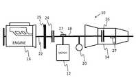
- FIG. 1is a schematic diagram of a hybrid powertrain, according to the principles of the present invention
- FIG. 2is a schematic diagram of another embodiment of a hybrid powertrain, according to the principles of the present invention.
- FIG. 3is a schematic diagram of another embodiment of a hybrid powertrain, according to the principles of the present invention.
- FIG. 4Ais a schematic diagram of a gear arrangement for a multi-speed transmission, according to the principles of the present invention.
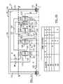
- FIG. 4Bis a schematic showing the locations of the torque transmitting devices for the arrangement of planetary gear sets of the transmission shown in FIG. 4A , in accordance with the embodiments of the present invention.
- the hybrid powertrain 10includes a first electric motor 12 , a multi-speed vehicle transmission 14 and an internal combustion engine 16 .
- First electric motor 12is permanently connected to an input shaft or member 18 of the vehicle transmission 14 .
- First electric motor 12is arranged between the internal combustion engine 16 and vehicle transmission 14 .
- Vehicle transmission 14has a changeable gear ratio and at least eight gear speeds which will be described in further detail hereinafter.
- the first electric machine 12can be operated as an engine for driving the motor vehicle and as a generator for charging the batteries.
- a hydraulic pump 20is provided, in addition, for operation and control of the vehicle transmission 14 . Hydraulic pump 20 is a binary pump that reduces pump losses in transmission 14 and therefore improves fuel economy.
- the engine output shaft or member 22 of the internal combustion engine 16is connected, via a first clutch device 24 , to the input shaft 18 of the vehicle transmission 14 , so that the internal combustion engine 16 is separated from the input shaft 18 of the vehicle transmission 14 when the clutch device 24 is disengaged.
- a second clutch device 26is provided on the input shaft 18 and is a clutch or brake of the vehicle transmission 14 and may be activated by electrically applied actuators.
- First and second clutch devices 24 , 26are friction clutches, synchronizing clutches or brakes or similar devices.
- a torsional vibration damper 25can be arranged in the powertrain 10 between the internal combustion engine 16 and the vehicle transmission 14 .
- a torsional vibration damper 25for example, a dual mass flywheel with a first mass as primary mass and a second mass as secondary mass, can be used but also any other suitable damping element is possible.
- the torsional vibration dampercan be connected indirectly, but also directly, via a so-called drive plate, to the crankshaft of the internal combustion engine in the proposed hybrid powertrain 10 .
- the present inventioncontemplates the use of torque sensors 27 attached to any of the shafts of powertrain 10 and transmission 14 to improve shift feel.
- the hydraulic pump 20is fixedly connected to the input shaft 18 of the vehicle transmission 14 and thus also to the first electric machine 12 .
- the hydraulic pump 20is configured to generate the required oil pressure to control and adjust various components of the vehicle transmission 14 .
- the present inventioncontemplates a starting procedure for the hybrid powertrain 10 shown in FIG. 1 .
- the starting procedureincludes when appropriate allowing the second clutch device 26 in the vehicle transmission 14 to slip as the first electric machine 12 rotates input shaft 18 . Accordingly, a thermally more robust design of the second clutch device 26 is required, unless the first clutch device 24 is designed as a startup clutch.
- the internal combustion engine 16can be started before the energy stores of the batteries are entirely emptied.
- FIG. 2Another embodiment is shown in FIG. 2 .
- the hydraulic pump 20is connected to a torque converter 28 .
- the hydraulic pump 20is driven by means of the torque converter 28 , which is connected to the input shaft 18 of the vehicle transmission 14 .
- the electric machine or motoris designed herein as a crankshaft starter generator 12 ′.
- FIG. 3a third exemplary embodiment of the hybrid drive is shown.
- the required oil pressure for the electric startupis generated by means of a smaller second electric machine 30 .
- the second electric machine 30is connected in a rotationally fixed manner to the hydraulic pump 20 of the vehicle transmission 14 .
- the hydraulic pump 20is connected, in turn, via a free-wheel clutch 32 , to the input shaft 18 of the vehicle transmission 14 .
- the hydraulic pump 20can be driven, via the second electric machine 30 , during an electric startup. As soon as the internal combustion engine 16 is activated or the rotational speed of the first electric machine 12 is greater than the rotational speed of the second electric machine 30 , the second electric machine 30 can be deactivated. This is possible because the hydraulic pump 20 is driven, via the engaged free-wheel clutch 32 by the internal combustion engine 16 or the first electric machine 12 .
- the oil pressure sufficient for controlling and adjusting the vehicle transmission 14is built up before driving the vehicle by means of the second electric machine 30 .
- the internal clutch or brake of the multi-speed transmission 14is engaged. The starting procedure is carried out exclusively via the first electric machine 12 . If the energy supply of the first electric machine 12 is insufficient, the internal combustion engine 16 is started, which is started with the first electric machine 12 by engaging the first clutch device 24 . With very strong accelerations, the driving force of the internal combustion engine 16 and the first electric machine 12 , are combined, via the first clutch device 24 .
- the transmission 14is illustrated as a rear-wheel drive or longitudinal transmission, though various other types of transmission configurations may be employed.
- the transmission 14includes a transmission housing 100 , an input shaft or member 120 , and an output shaft or member 140 .
- the input member 120is continuously connected to an engine (not shown) or to a turbine of a torque converter (not shown).
- the output member 140is continuously connected with a final drive unit (not shown) or transfer case (not shown).
- the transmission 14includes a first planetary gear set 160 , a second planetary gear set 180 , a third planetary gear set 200 , and a fourth planetary gear set 220 .
- the planetary gear sets 160 , 180 , 200 and 220are connected between the input member 120 and the output member 140 .
- the planetary gear set 160includes a sun gear member 162 , a ring gear member 164 , and a planet carrier member 166 that rotatably supports a set of planet or pinion gears 168 (only one of which is shown).
- the pinion gears 168are each configured to intermesh with both the sun gear member 162 and the ring gear member 164 .
- the sun gear member 162is connected for common rotation with a first shaft or intermediate member 170 and a second shaft or intermediate member 172 . It should be appreciated that the first intermediate member 170 is connected for common rotation with the second intermediate member 172 and that the intermediate members 170 and 172 may form one single shaft or multiple shafts through one or more members of the planetary gear sets, as seen throughout the several views.
- the ring gear member 164is connected for common rotation with a third shaft or intermediate member 174 .
- the planet carrier member 166is connected for common rotation with a fourth shaft or intermediate member 176 .
- the planetary gear set 180includes a sun gear member 182 , a ring gear member 184 , and a planet carrier member 186 that rotatably supports a set of planet or pinion gears 188 .
- the pinion gears 188are each configured to intermesh with both the sun gear member 182 and the ring gear member 184 .
- the sun gear member 182is connected for common rotation with the second intermediate member 172 .
- the ring gear member 184is connected for common rotation with a fifth shaft or intermediate member 178 .
- the planet carrier member 186is connected for common rotation with the input member 120 .
- the planetary gear set 200includes a sun gear member 202 , a ring gear member 204 , and a carrier member 206 that rotatably supports a set of planet or pinion gears 208 .
- the pinion gears 208are each configured to intermesh with both the sun gear member 202 and the ring gear member 204 .
- the sun gear member 202is connected for common rotation with the fifth shaft or intermediate member 178 and with a sixth shaft or intermediate member 190 . It should be appreciated that the fifth intermediate member 178 is connected for common rotation with the sixth intermediate member 190 and that the intermediate members 178 and 190 may form one single shaft or multiple shafts through one or more members of the planetary gear sets, as seen throughout the several views.
- the ring gear member 204is connected for common rotation with a seventh shaft or intermediate member 192 .
- the planet carrier member 206is connected for common rotation with an eighth shaft or intermediate member 194 .
- the eighth intermediate member 194is connected for common rotation with the output member 140 and that the eighth intermediate members 194 and the output member 140 may form one single shaft or multiple shafts through one or more members of the planetary gear sets, as seen throughout the several views.
- the planetary gear set 220includes a sun gear member 222 , a ring gear member 224 , and a planet carrier member 226 that rotatably supports a set of planet or pinion gears 228 .
- the pinion gears 228are each configured to intermesh with both the sun gear member 222 and the ring gear member 224 .
- the sun gear member 222is connected for common rotation with a ninth shaft or intermediate member 196 and a tenth shaft or intermediate member 198 . It should be appreciated that the ninth intermediate member 196 is connected for common rotation with the tenth intermediate member 198 and that the intermediate members 196 and 198 may form one single shaft or multiple shafts through one or more members of the planetary gear sets, as seen throughout the several views.
- the ring gear member 224is connected for common rotation with the fourth intermediate member 176 .
- the planet carrier member 226is connected for common rotation with the output member 140 and with the eighth intermediate member 194 .
- the transmission 14includes a variety of torque-transmitting mechanisms or devices including a first clutch C 1 , a second clutch C 2 , a third clutch C 3 , a first brake B 1 and a second brake B 2 .
- the first clutch C 1is selectively engagable to connect the input member 120 to the tenth intermediate member 198 .
- the second clutch C 2is selectively engagable to connect the sixth intermediate member 190 to the ninth intermediate member 196 .
- the third intermediate clutch C 3is selectively engagable to connect the seventh intermediate member 192 to the ninth intermediate member 196 .
- the first brake B 1is selectively engagable to connect the first intermediate member 170 to the transmission housing 100 to restrict rotation of the first intermediate member 170 relative to the transmission housing 100 .
- the second brake B 2is selectively engagable to connect the third intermediate member 174 to the transmission housing 100 to restrict rotation of the third intermediate member 174 relative to the transmission housing 100 .
- the transmission 14is capable of transmitting torque from the input member 120 to the output member 140 in at least eight forward torque ratios and one reverse torque ratio.
- Each of the forward torque ratios and the reverse torque ratioare attained by engagement of one or more of the torque-transmitting mechanisms (i.e. first intermediate clutch C 1 , second intermediate clutch C 2 , third intermediate clutch C 3 , firs brake B 1 and second brake B 2 ).
- first intermediate clutch C 1second intermediate clutch C 2
- third intermediate clutch C 3i.e. first intermediate clutch C 1 , second intermediate clutch C 2 , third intermediate clutch C 3 , firs brake B 1 and second brake B 2 .
- the transmission housing 100includes a first end wall 102 , a second end wall 104 , and a third wall 106 .
- the third wall 106interconnects between the first and second end walls 102 and 104 to provide a space or cavity 108 in which planetary gear sets 160 , 180 , 200 , and 220 and the torque-transmitting mechanisms C 1 , C 2 , C 3 , B 1 , and B 2 are located.
- the cavity 108has a plurality of areas or Zones A, B, C, D, E, and F in which the plurality of torque transmitting mechanisms C 1 , C 2 , C 3 , B 1 , and B 2 will be specifically positioned, in accordance with the preferred embodiments of the present invention.
- Zone Ais defined by the area or space bounded: axially on the left by the first end wall 102 , on the right by planetary gear set 160 , radially inward by a reference line “L” which is a longitudinal line that is axially aligned with the input shaft 120 , and radially outward by a reference line “M” which is a longitudinal line that extends adjacent an outer diameter or outer periphery of the planetary gear sets 160 , 180 , 200 , and 220 .
- Zone Bis defined by the area bounded: axially on the left by planetary gear set 160 , axially on the right by the planetary gear set 180 , radially outward by reference line “M”, and radially inward by reference line “L”.
- Zone Cis defined by the area bounded: axially on the left by the planetary gear set 180 , axially on the right by the planetary gear set 200 , radially outward by reference line “M”, and radially inward by reference line “L”.
- Zone Dis defined by the area bounded: axially on the left by the planetary gear set 200 , axially on the right by the planetary gear set 220 , radially outward by reference line “M”, and radially inward by reference line “L”.
- Zone Eis defined by the area bounded: axially on the left by the planetary gear set 220 , axially on the right by the second end wall 104 , radially outward by reference line “M”, and radially inward by reference line “L”.
- Zone Fis defined by the area bounded: axially on the left by the first end wall 102 , axially on the right by the second end wall 104 , radially inward by reference line “M” and radially outward by the third wall 106 .
- planetary gear sets 160 , 180 , 200 , and 220will change positions within the transmission cavity 108 , however, the Zones described above will not change and will remain the same as shown throughout the Figures.
- the planetary gear sets 160 , 180 , 200 , and 220are longitudinally arranged in the following order from left to right: 160 - 180 - 200 - 220 .
- the planetary gear set 160is disposed closest to the wall 102
- the planetary gear set 220is disposed closest to the wall 104
- the planetary gear set 180is adjacent the planetary gear set 160
- the planetary gear set 200is disposed between the planetary gear sets 180 and 220 .
- the torque-transmitting mechanismsare intentionally located within specific Zones in order to provide advantages in overall transmission size, packaging efficiency, and reduced manufacturing complexity.
- the torque-transmitting mechanism C 1is disposed within Zone C
- the torque-transmitting mechanisms C 2 and C 3are disposed within Zone D
- the torque-transmitting mechanisms B 1 and B 2are disposed within Zone F.
- the present inventioncontemplates other embodiments where the torque-transmitting mechanisms C 1 , C 2 , C 3 , B 1 , and B 2 are disposed in the other Zones.
- the feasible locations of the torque-transmitting devices C 1 , C 2 , C 3 , B 1 , and B 2 relative to the Zonesare illustrated in the chart shown in FIG. 4B .
- An “X” in the chartindicates that the present invention contemplates locating the particular torque-transmitting device in any of the referenced Zones.
Landscapes
- Engineering & Computer Science (AREA)
- General Engineering & Computer Science (AREA)
- Mechanical Engineering (AREA)
- Chemical & Material Sciences (AREA)
- Combustion & Propulsion (AREA)
- Transportation (AREA)
- Structure Of Transmissions (AREA)
- Hybrid Electric Vehicles (AREA)
Abstract
Description
Claims (16)
Priority Applications (3)
| Application Number | Priority Date | Filing Date | Title |
|---|---|---|---|
| US12/425,633US8206252B2 (en) | 2008-05-09 | 2009-04-17 | Hybrid powertrain having a multi-speed transmission |
| DE102009020177ADE102009020177A1 (en) | 2008-05-09 | 2009-05-06 | Hybrid powertrain with a multi-speed transmission |
| CN2009101410144ACN101574922B (en) | 2008-05-09 | 2009-05-08 | Hybrid powertrain having a multi-speed transmission |
Applications Claiming Priority (2)
| Application Number | Priority Date | Filing Date | Title |
|---|---|---|---|
| US5176208P | 2008-05-09 | 2008-05-09 | |
| US12/425,633US8206252B2 (en) | 2008-05-09 | 2009-04-17 | Hybrid powertrain having a multi-speed transmission |
Publications (2)
| Publication Number | Publication Date |
|---|---|
| US20090280941A1 US20090280941A1 (en) | 2009-11-12 |
| US8206252B2true US8206252B2 (en) | 2012-06-26 |
Family
ID=41267333
Family Applications (1)
| Application Number | Title | Priority Date | Filing Date |
|---|---|---|---|
| US12/425,633Expired - Fee RelatedUS8206252B2 (en) | 2008-05-09 | 2009-04-17 | Hybrid powertrain having a multi-speed transmission |
Country Status (3)
| Country | Link |
|---|---|
| US (1) | US8206252B2 (en) |
| CN (1) | CN101574922B (en) |
| DE (1) | DE102009020177A1 (en) |
Cited By (3)
| Publication number | Priority date | Publication date | Assignee | Title |
|---|---|---|---|---|
| US20100267518A1 (en)* | 2009-04-20 | 2010-10-21 | Versteyhe Mark R J | Hybrid Transmission and Method of Use |
| US20130239750A1 (en)* | 2010-12-07 | 2013-09-19 | Dr. Ing. H.C.F. Porsche Aktiengesellschaft | Modular system |
| US8702545B2 (en)* | 2009-11-05 | 2014-04-22 | Denso Corporation | Power transmission system for use in vehicle |
Families Citing this family (31)
| Publication number | Priority date | Publication date | Assignee | Title |
|---|---|---|---|---|
| US7775931B2 (en)* | 2007-03-16 | 2010-08-17 | Gm Global Technology Operations, Inc. | Multi-speed transmission |
| US7998015B2 (en)* | 2008-04-17 | 2011-08-16 | GM Global Technology Operations LLC | Multi-speed transaxle for a front wheel drive vehicle |
| US8292767B2 (en) | 2008-06-04 | 2012-10-23 | GM Global Technology Operations LLC | Powertrain having a multi-speed transmission |
| DE102008041067A1 (en)* | 2008-08-07 | 2010-02-11 | Robert Bosch Gmbh | Pressure pump device for a hybrid vehicle |
| US8826877B2 (en)* | 2009-10-15 | 2014-09-09 | GM Global Technology Operations LLC | Flexible mounting system for powertrain mounted components |
| CN101898504A (en)* | 2010-08-06 | 2010-12-01 | 上海交通大学 | Dual Clutch Motor Suspension Parallel Hybrid Drive System |
| US8371984B2 (en) | 2010-09-17 | 2013-02-12 | GM Global Technology Operations LLC | Multi-speed transmission having automatic and manual modes |
| US8357069B2 (en) | 2010-09-17 | 2013-01-22 | GM Global Technology Operations LLC | Multi-speed transmission having automatic and manual modes |
| DE102010041172A1 (en)* | 2010-09-22 | 2012-03-22 | Robert Bosch Gmbh | Hand-held power tool with a gearbox |
| US8701851B2 (en) | 2010-10-08 | 2014-04-22 | GM Global Technology Operations LLC | Selectable mass flywheel |
| CN101985274B (en)* | 2010-11-12 | 2012-12-19 | 北京航空航天大学 | Five-gear automatic transmission-based hybrid vehicle transmission system |
| DE112011104488A5 (en)* | 2010-12-21 | 2013-09-26 | Schaeffler Technologies AG & Co. KG | Hybrid module for a drive train of a vehicle |
| US8795118B2 (en)* | 2011-03-04 | 2014-08-05 | Chrysler Group Llc | Electric motor assist for transmission electric oil pump |
| DE102011102789A1 (en)* | 2011-03-08 | 2012-09-13 | Getrag Getriebe- Und Zahnradfabrik Hermann Hagenmeyer Gmbh & Co. Kg | Hybrid powertrain |
| US8556765B2 (en) | 2011-08-24 | 2013-10-15 | GM Global Technology Operations LLC | Multi-speed transmission with an engine start/stop enabler |
| US9353692B2 (en) | 2011-12-12 | 2016-05-31 | Fca Us Llc | Start-up strategy for hybrid powertrain |
| US9050882B2 (en)* | 2012-04-04 | 2015-06-09 | Gm Global Technology Operations, Llc | Hybrid powertrain |
| US9260107B2 (en) | 2012-05-04 | 2016-02-16 | Ford Global Technologies, Llc | Methods and systems for operating a driveline disconnect clutch responsive to engine operating conditions |
| CN102829140A (en)* | 2012-08-24 | 2012-12-19 | 北京理工大学 | Automatic eight-gear hybrid gearbox |
| DE102013222893A1 (en)* | 2012-12-11 | 2014-06-12 | Schaeffler Technologies Gmbh & Co. Kg | Axis for a motor car, has second drive unit that is adapted for driving rotatable second shaft and freewheel, and rotatable second shaft that is driven by freewheel in rotation direction of rotatable first shaft |
| US9050968B2 (en)* | 2012-12-17 | 2015-06-09 | Caterpillar Inc. | Hybrid engine assembly and method |
| US8961356B2 (en) | 2013-06-19 | 2015-02-24 | Gm Global Technology Operations, Llc | Ten speed transmission with latching mechanisms |
| US9074664B2 (en) | 2013-06-19 | 2015-07-07 | Gm Global Technology Operations, Llc | Nine speed transmission with latching mechanism |
| US9028359B2 (en) | 2013-07-09 | 2015-05-12 | Gm Global Technology Operations, Llc | Multi-speed transmission with an engine start/stop enabler |
| DE112014003539A5 (en)* | 2013-07-31 | 2016-05-04 | Schaeffler Technologies AG & Co. KG | VEHICLE WITH PULLEY AND STAND-LEVELING |
| DE102013112388A1 (en) | 2013-11-11 | 2015-05-13 | Hofer Forschungs- Und Entwicklungs Gmbh | Alternative drive concept for motor vehicles with internal combustion engine and electric machine |
| KR102181294B1 (en)* | 2014-05-27 | 2020-11-20 | 두산인프라코어 주식회사 | Wheel driving system for construction machinery |
| DE102017206836B4 (en)* | 2017-04-24 | 2024-07-25 | Zf Friedrichshafen Ag | Gearbox for a motor vehicle |
| CN108999950A (en)* | 2018-09-30 | 2018-12-14 | 山推工程机械股份有限公司 | A kind of full hydraulic bulldozer variable-ratio final drive and bull-dozer |
| CN109747624B (en)* | 2018-12-06 | 2020-07-28 | 同济大学 | A hybrid electric vehicle start-stop control system |
| US11413960B2 (en) | 2019-07-12 | 2022-08-16 | Deere & Company | Power shift transmission with electric power assist |
Citations (21)
| Publication number | Priority date | Publication date | Assignee | Title |
|---|---|---|---|---|
| US6081042A (en)* | 1996-03-22 | 2000-06-27 | Toyota Jidosha Kabushiki Kaisha | Hybrid vehicle drive system including controllable device between engine and electric motor and vehicle drive wheels, and apparatus for controlling the device depending upon selected operation mode of the system |
| US6176803B1 (en) | 1999-09-28 | 2001-01-23 | Caterpillar Inc. | Transmission assembly with four planetary gear sets providing nine forward and one reverse gear ratio |
| US6558287B2 (en) | 2001-03-29 | 2003-05-06 | Aisin Aw Co., Ltd. | Automatic transmission for a vehicle |
| US20050090362A1 (en) | 2003-10-27 | 2005-04-28 | Toyota Jidosha Kabushiki Kaisha | Planetary-gear-type multiple-step transmission for vehicle |
| US6984187B2 (en) | 2001-03-30 | 2006-01-10 | Zf Friedrichshafen Ag | Multi-stage gearbox |
| US6991578B2 (en) | 2001-03-30 | 2006-01-31 | Zf Friedrichshafen Ag | Multistep gear |
| US7011597B2 (en) | 2004-03-24 | 2006-03-14 | General Motors Corporation | Multi-speed transmission |
| US7101305B2 (en) | 2003-05-27 | 2006-09-05 | Toyota Jidosha Kabushiki Kaisha | Planetary-gear-type multiple-step transmission for vehicle |
| US20060270513A1 (en) | 2005-05-25 | 2006-11-30 | Donald Klemen | Multi-speed transmission |
| US20060270516A1 (en) | 2005-05-25 | 2006-11-30 | Donald Klemen | Multi speed transmission |
| US7163484B2 (en) | 2005-01-24 | 2007-01-16 | General Motors Corporation | Eight-speed transmissions with four planetary gear sets |
| DE102005032001A1 (en) | 2005-07-08 | 2007-02-01 | Zf Friedrichshafen Ag | Multi-speed transmission |
| US20080011529A1 (en)* | 2006-07-14 | 2008-01-17 | Zf Friedrichshafen Ag | Hybrid drive for a vehicle |
| US20080227587A1 (en)* | 2007-03-16 | 2008-09-18 | Carey Clinton E | Multi-speed transmission |
| US20090209390A1 (en)* | 2008-02-20 | 2009-08-20 | Gm Global Technology Operations, Inc. | Multi-speed transaxle for a front wheel drive vehicle |
| US20090209391A1 (en)* | 2008-02-20 | 2009-08-20 | Gm Global Technology Operations, Inc. | Multi-speed transaxle for a front wheel drive vehicle |
| US20090264238A1 (en) | 2008-04-17 | 2009-10-22 | Gm Global Technology Operations, Inc. | Multi-speed transaxle for a front wheel drive vehicle |
| US20090305838A1 (en) | 2008-06-04 | 2009-12-10 | Gm Global Technology Operations, Inc. | Powertrain having a multi-speed transmission |
| US7699741B2 (en)* | 2007-01-25 | 2010-04-20 | Gm Global Technology Operations, Inc. | Multi-speed transmission |
| US7736264B2 (en)* | 2007-06-08 | 2010-06-15 | Gm Global Technology Operations, Inc. | Eight speed automatic transmission with dual area clutch piston |
| US8012059B2 (en)* | 2007-05-30 | 2011-09-06 | GM Global Technology Operations LLC | Multi-speed automatic transmission |
Family Cites Families (4)
| Publication number | Priority date | Publication date | Assignee | Title |
|---|---|---|---|---|
| US5542889A (en)* | 1994-12-27 | 1996-08-06 | Ford Motor Company | Multiple-speed automatic transmission for a motor vehicle |
| DE10162888A1 (en)* | 2001-12-20 | 2003-07-10 | Zahnradfabrik Friedrichshafen | Multi-stage transmission has drive shaft directly connected to input stage presetting element |
| US6743140B1 (en)* | 2002-12-18 | 2004-06-01 | General Motors Corporation | Family of six-speed dual-clutch transmissions having two stationary planetary gear members |
| JP4534920B2 (en)* | 2005-09-12 | 2010-09-01 | マツダ株式会社 | Automatic transmission |
- 2009
- 2009-04-17USUS12/425,633patent/US8206252B2/ennot_activeExpired - Fee Related
- 2009-05-06DEDE102009020177Apatent/DE102009020177A1/ennot_activeWithdrawn
- 2009-05-08CNCN2009101410144Apatent/CN101574922B/ennot_activeExpired - Fee Related
Patent Citations (24)
| Publication number | Priority date | Publication date | Assignee | Title |
|---|---|---|---|---|
| US6081042A (en)* | 1996-03-22 | 2000-06-27 | Toyota Jidosha Kabushiki Kaisha | Hybrid vehicle drive system including controllable device between engine and electric motor and vehicle drive wheels, and apparatus for controlling the device depending upon selected operation mode of the system |
| US6176803B1 (en) | 1999-09-28 | 2001-01-23 | Caterpillar Inc. | Transmission assembly with four planetary gear sets providing nine forward and one reverse gear ratio |
| US6558287B2 (en) | 2001-03-29 | 2003-05-06 | Aisin Aw Co., Ltd. | Automatic transmission for a vehicle |
| US6984187B2 (en) | 2001-03-30 | 2006-01-10 | Zf Friedrichshafen Ag | Multi-stage gearbox |
| US6991578B2 (en) | 2001-03-30 | 2006-01-31 | Zf Friedrichshafen Ag | Multistep gear |
| US7018319B2 (en) | 2001-03-30 | 2006-03-28 | Zf Friedrichshafen Ag | Multistep gear |
| US7101305B2 (en) | 2003-05-27 | 2006-09-05 | Toyota Jidosha Kabushiki Kaisha | Planetary-gear-type multiple-step transmission for vehicle |
| US20050090362A1 (en) | 2003-10-27 | 2005-04-28 | Toyota Jidosha Kabushiki Kaisha | Planetary-gear-type multiple-step transmission for vehicle |
| US7011597B2 (en) | 2004-03-24 | 2006-03-14 | General Motors Corporation | Multi-speed transmission |
| US7163484B2 (en) | 2005-01-24 | 2007-01-16 | General Motors Corporation | Eight-speed transmissions with four planetary gear sets |
| US20060270513A1 (en) | 2005-05-25 | 2006-11-30 | Donald Klemen | Multi-speed transmission |
| US20060270516A1 (en) | 2005-05-25 | 2006-11-30 | Donald Klemen | Multi speed transmission |
| DE102005032001A1 (en) | 2005-07-08 | 2007-02-01 | Zf Friedrichshafen Ag | Multi-speed transmission |
| US20080011529A1 (en)* | 2006-07-14 | 2008-01-17 | Zf Friedrichshafen Ag | Hybrid drive for a vehicle |
| US7828096B2 (en)* | 2006-07-14 | 2010-11-09 | Zf Friedrichshafen Ag | Hybrid drive for a vehicle |
| US7699741B2 (en)* | 2007-01-25 | 2010-04-20 | Gm Global Technology Operations, Inc. | Multi-speed transmission |
| US20080227587A1 (en)* | 2007-03-16 | 2008-09-18 | Carey Clinton E | Multi-speed transmission |
| US7775931B2 (en)* | 2007-03-16 | 2010-08-17 | Gm Global Technology Operations, Inc. | Multi-speed transmission |
| US8012059B2 (en)* | 2007-05-30 | 2011-09-06 | GM Global Technology Operations LLC | Multi-speed automatic transmission |
| US7736264B2 (en)* | 2007-06-08 | 2010-06-15 | Gm Global Technology Operations, Inc. | Eight speed automatic transmission with dual area clutch piston |
| US20090209390A1 (en)* | 2008-02-20 | 2009-08-20 | Gm Global Technology Operations, Inc. | Multi-speed transaxle for a front wheel drive vehicle |
| US20090209391A1 (en)* | 2008-02-20 | 2009-08-20 | Gm Global Technology Operations, Inc. | Multi-speed transaxle for a front wheel drive vehicle |
| US20090264238A1 (en) | 2008-04-17 | 2009-10-22 | Gm Global Technology Operations, Inc. | Multi-speed transaxle for a front wheel drive vehicle |
| US20090305838A1 (en) | 2008-06-04 | 2009-12-10 | Gm Global Technology Operations, Inc. | Powertrain having a multi-speed transmission |
Cited By (5)
| Publication number | Priority date | Publication date | Assignee | Title |
|---|---|---|---|---|
| US20100267518A1 (en)* | 2009-04-20 | 2010-10-21 | Versteyhe Mark R J | Hybrid Transmission and Method of Use |
| US8353804B2 (en)* | 2009-04-20 | 2013-01-15 | Spicer Off-Highway Belguim N.V. | Hybrid transmission and method of use |
| US8702545B2 (en)* | 2009-11-05 | 2014-04-22 | Denso Corporation | Power transmission system for use in vehicle |
| US20130239750A1 (en)* | 2010-12-07 | 2013-09-19 | Dr. Ing. H.C.F. Porsche Aktiengesellschaft | Modular system |
| US9227502B2 (en)* | 2010-12-07 | 2016-01-05 | Dr. Ing. H.C. F. Porsche Aktiengesellschaft | Modular system |
Also Published As
| Publication number | Publication date |
|---|---|
| CN101574922B (en) | 2013-03-06 |
| DE102009020177A1 (en) | 2009-12-24 |
| CN101574922A (en) | 2009-11-11 |
| US20090280941A1 (en) | 2009-11-12 |
Similar Documents
| Publication | Publication Date | Title |
|---|---|---|
| US8206252B2 (en) | Hybrid powertrain having a multi-speed transmission | |
| US7828096B2 (en) | Hybrid drive for a vehicle | |
| US9772028B2 (en) | Hybrid transmission arrangement having a motor damper | |
| US9073538B2 (en) | Two-speed electric drive module for electric and hybrid vehicles | |
| US8235853B2 (en) | Hybrid transmissions with planetary gearsets | |
| US8197378B2 (en) | Multi-speed transaxle for a front wheel drive vehicle | |
| US8123650B2 (en) | Multi-speed transaxle for a front wheel drive vehicle | |
| US8123651B2 (en) | Multi-speed transaxle for a front wheel drive vehicle | |
| US8187138B2 (en) | Multi-speed transaxle for a front wheel drive vehicle | |
| US8157696B2 (en) | Multi-speed transaxle for a front wheel drive vehicle | |
| US8118700B2 (en) | Multi-speed transmission for a front wheel drive vehicle | |
| US8123652B2 (en) | Multi-speed transaxle for a front wheel drive vehicle | |
| US20140290406A1 (en) | Accessory devices drive system | |
| US20120178573A1 (en) | Hybrid powertrain for a motor vehicle | |
| US10543740B2 (en) | Lockup clutch for powersplit hybrid transmission | |
| US20120035013A1 (en) | Hybrid drive arrangement | |
| US7022038B2 (en) | Two-mode compound-split electrically variable transmission | |
| CN109538716B (en) | Lock-up clutch for power-split hybrid transmission | |
| JP2010143264A (en) | Automatic transmission | |
| US10315503B2 (en) | Transmission for a motor vehicle and hybrid drive train provided therewith | |
| WO2015142270A1 (en) | Method for starting a combustion engine in a hybrid driveline | |
| US6863635B2 (en) | Speed change mechanism of automatic transmission | |
| US11180016B2 (en) | Power system for hybrid vehicle | |
| US10308107B2 (en) | Multi-mode hybrid powertrain |
Legal Events
| Date | Code | Title | Description |
|---|---|---|---|
| AS | Assignment | Owner name:GM GLOBAL TECHNOLOGY OPERATIONS, INC., MICHIGAN Free format text:ASSIGNMENT OF ASSIGNORS INTEREST;ASSIGNORS:DUSENBERRY, DONALD L.;BORGERSON, JAMES B.;HART, JAMES M.;AND OTHERS;REEL/FRAME:022570/0200 Effective date:20090417 | |
| AS | Assignment | Owner name:UNITED STATES DEPARTMENT OF THE TREASURY, DISTRICT Free format text:SECURITY AGREEMENT;ASSIGNOR:GM GLOBAL TECHNOLOGY OPERATIONS, INC.;REEL/FRAME:023201/0118 Effective date:20090710 Owner name:UNITED STATES DEPARTMENT OF THE TREASURY,DISTRICT Free format text:SECURITY AGREEMENT;ASSIGNOR:GM GLOBAL TECHNOLOGY OPERATIONS, INC.;REEL/FRAME:023201/0118 Effective date:20090710 | |
| AS | Assignment | Owner name:UAW RETIREE MEDICAL BENEFITS TRUST, MICHIGAN Free format text:SECURITY AGREEMENT;ASSIGNOR:GM GLOBAL TECHNOLOGY OPERATIONS, INC.;REEL/FRAME:023162/0048 Effective date:20090710 Owner name:UAW RETIREE MEDICAL BENEFITS TRUST,MICHIGAN Free format text:SECURITY AGREEMENT;ASSIGNOR:GM GLOBAL TECHNOLOGY OPERATIONS, INC.;REEL/FRAME:023162/0048 Effective date:20090710 | |
| AS | Assignment | Owner name:GM GLOBAL TECHNOLOGY OPERATIONS, INC., MICHIGAN Free format text:RELEASE BY SECURED PARTY;ASSIGNOR:UNITED STATES DEPARTMENT OF THE TREASURY;REEL/FRAME:025246/0056 Effective date:20100420 | |
| AS | Assignment | Owner name:GM GLOBAL TECHNOLOGY OPERATIONS, INC., MICHIGAN Free format text:RELEASE BY SECURED PARTY;ASSIGNOR:UAW RETIREE MEDICAL BENEFITS TRUST;REEL/FRAME:025315/0091 Effective date:20101026 | |
| AS | Assignment | Owner name:WILMINGTON TRUST COMPANY, DELAWARE Free format text:SECURITY AGREEMENT;ASSIGNOR:GM GLOBAL TECHNOLOGY OPERATIONS, INC.;REEL/FRAME:025324/0555 Effective date:20101027 | |
| AS | Assignment | Owner name:GM GLOBAL TECHNOLOGY OPERATIONS LLC, MICHIGAN Free format text:CHANGE OF NAME;ASSIGNOR:GM GLOBAL TECHNOLOGY OPERATIONS, INC.;REEL/FRAME:025781/0245 Effective date:20101202 | |
| FEPP | Fee payment procedure | Free format text:PAYOR NUMBER ASSIGNED (ORIGINAL EVENT CODE: ASPN); ENTITY STATUS OF PATENT OWNER: LARGE ENTITY | |
| STCF | Information on status: patent grant | Free format text:PATENTED CASE | |
| AS | Assignment | Owner name:GM GLOBAL TECHNOLOGY OPERATIONS LLC, MICHIGAN Free format text:RELEASE BY SECURED PARTY;ASSIGNOR:WILMINGTON TRUST COMPANY;REEL/FRAME:034185/0789 Effective date:20141017 | |
| FPAY | Fee payment | Year of fee payment:4 | |
| FEPP | Fee payment procedure | Free format text:MAINTENANCE FEE REMINDER MAILED (ORIGINAL EVENT CODE: REM.); ENTITY STATUS OF PATENT OWNER: LARGE ENTITY | |
| LAPS | Lapse for failure to pay maintenance fees | Free format text:PATENT EXPIRED FOR FAILURE TO PAY MAINTENANCE FEES (ORIGINAL EVENT CODE: EXP.); ENTITY STATUS OF PATENT OWNER: LARGE ENTITY | |
| STCH | Information on status: patent discontinuation | Free format text:PATENT EXPIRED DUE TO NONPAYMENT OF MAINTENANCE FEES UNDER 37 CFR 1.362 | |
| FP | Lapsed due to failure to pay maintenance fee | Effective date:20200626 |