US8206181B2 - Connector arrangement - Google Patents
Connector arrangementDownload PDFInfo
- Publication number
- US8206181B2 US8206181B2US12/431,798US43179809AUS8206181B2US 8206181 B2US8206181 B2US 8206181B2US 43179809 AUS43179809 AUS 43179809AUS 8206181 B2US8206181 B2US 8206181B2
- Authority
- US
- United States
- Prior art keywords
- connector
- ring
- contact
- connector arrangement
- elongate member
- Prior art date
- Legal status (The legal status is an assumption and is not a legal conclusion. Google has not performed a legal analysis and makes no representation as to the accuracy of the status listed.)
- Expired - Fee Related
Links
- 239000012212insulatorSubstances0.000claimsdescription26
- 238000009413insulationMethods0.000claimsdescription9
- 238000003780insertionMethods0.000claimsdescription4
- 230000037431insertionEffects0.000claimsdescription4
- 230000008878couplingEffects0.000claimsdescription2
- 238000010168coupling processMethods0.000claimsdescription2
- 238000005859coupling reactionMethods0.000claimsdescription2
- 238000001746injection mouldingMethods0.000description4
- 239000011810insulating materialSubstances0.000description4
- 238000004519manufacturing processMethods0.000description4
- 239000000463materialSubstances0.000description4
- 239000002184metalSubstances0.000description4
- 238000000034methodMethods0.000description3
- 230000004048modificationEffects0.000description2
- 238000012986modificationMethods0.000description2
- 238000000465mouldingMethods0.000description2
- 238000000638solvent extractionMethods0.000description2
- 239000004020conductorSubstances0.000description1
- 230000003287optical effectEffects0.000description1
- 230000004044responseEffects0.000description1
- 230000008054signal transmissionEffects0.000description1
- 230000005236sound signalEffects0.000description1
Images


Classifications
- H—ELECTRICITY
- H01—ELECTRIC ELEMENTS
- H01R—ELECTRICALLY-CONDUCTIVE CONNECTIONS; STRUCTURAL ASSOCIATIONS OF A PLURALITY OF MUTUALLY-INSULATED ELECTRICAL CONNECTING ELEMENTS; COUPLING DEVICES; CURRENT COLLECTORS
- H01R24/00—Two-part coupling devices, or either of their cooperating parts, characterised by their overall structure
- H01R24/58—Contacts spaced along longitudinal axis of engagement
- H—ELECTRICITY
- H01—ELECTRIC ELEMENTS
- H01R—ELECTRICALLY-CONDUCTIVE CONNECTIONS; STRUCTURAL ASSOCIATIONS OF A PLURALITY OF MUTUALLY-INSULATED ELECTRICAL CONNECTING ELEMENTS; COUPLING DEVICES; CURRENT COLLECTORS
- H01R2105/00—Three poles
- H—ELECTRICITY
- H01—ELECTRIC ELEMENTS
- H01R—ELECTRICALLY-CONDUCTIVE CONNECTIONS; STRUCTURAL ASSOCIATIONS OF A PLURALITY OF MUTUALLY-INSULATED ELECTRICAL CONNECTING ELEMENTS; COUPLING DEVICES; CURRENT COLLECTORS
- H01R2107/00—Four or more poles
Definitions
- the present inventionrelates to connector arrangements.
- Connectors and connector arrangementare commonly used to electrically connect two devices with each other.
- One type of connectorsare audio connectors which are for example used to connect headphones or loudspeakers to audio equipment, for example portable or non-portable audio equipment, cell phones, personal computers, and the like.
- Commonly used audio connectorsinclude 6.35 mm, 3.5 mm or 2.5 mm audio connectors.
- the male form of such audio connectorsusually comprise a generally elongate member with different areas of the circumferential surface being electrically insulated from each other to provide a plurality of contacts.
- TSTip Sleeve
- TRSTip Ring Sleeve
- TRRSTip Ring Ring Sleeve
- a tip contactis insulated from a sleeve contact which is generally adjacent to the head, with no, one or two so-called ring contacts in between.
- a TS connectormay be used for mono audio
- TRS connectormay be used for stereo audio
- TRRS connectormay be used for stereo audio with an additional signal, for example a video signal.
- Corresponding female connectors to the above-described male audio connectorsmay have an elongate hole with contact elements arranged therein corresponding to the positions of the insulated areas mentioned above.
- These audio connectorshave a basically standardized shape, such that for example headphones manufactured by one manufacturer may be used with portable audio equipment like a MP3 player from another manufacturer.
- audio devicesBesides female audio connectors, many audio devices have further connectors for further purposes, for example an antenna connector, a power connector, a data connector and the like. Such a plurality of connectors sometimes makes it difficult for a user to use the device since each device, cable or the like has to be plugged into the right connector.
- a device like loudspeakers or headphonesare provided with additional functions, such a device may have more than one connector, for example to receive audio signals and power from the audio device, which makes connecting the device with the audio device somewhat inconvenient.
- a connector arrangementcomprising:
- the elongate membermay have the form of a standard audio connector.
- the standard audio connectormay be selected from the group consisting of a 3.5 mm audio connector, a 2.5 mm audio connector and a 6.35 mm audio connector.
- said at least one ring areamay comprise a plurality of ring areas.
- said plurality of ring areasmay comprise a first ring area, a second ring area and a third ring area, said third ring area being arranged at said sleeve end of said connector to form a sleeve area, each of said first ring area, second ring area and third ring area comprising a first contact element and a second contact element.
- the connectormay further comprise a tip contact at said tip end.
- said elongate membermay comprise a first conducting element defining said first contact element
- Said first conducting element and said second conducting elementmay each comprise at least one ring-shaped portion.
- the connectormay further comprise a guiding element configured to aid an insertion of the connector arrangement into a receptacle with a defined orientation.
- the guiding elementmay comprise at least one element selected from the group consisting of a protrusion, a ridge, a slit and a groove.
- a receptacle for a connector arrangementcomprising:
- the receptaclemay further comprise a guiding element configured to provide a defined orientation for the insertion of the connector arrangement into the receptacle.
- Said guiding element of said receptaclemay comprise at least one element selected from the group consisting of a cut-out, a ridge, a groove, a slit and a protrusion.
- the receptaclemay further comprise a sensor configured to detect coupling of a further guiding element of a connector arrangement with said guiding element.
- a method for manufacturing a connectorcomprising:
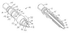
- FIG. 1is a perspective view of a connector arrangement according to an embodiment of the present invention.
- FIG. 1Ais an enlarged partial sectional view of the connector arrangement of the embodiment of FIG. 1 .
- FIG. 2is a perspective view of conducting portions of the embodiment of FIG. 1 .
- FIG. 3is a perspective view of further conducting portions of the embodiment of FIG. 1 .
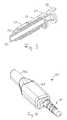
- FIG. 4shows the connector arrangement of FIG. 1 with a housing and a cable attached thereto according to an embodiment.
- FIG. 5shows a receptacle for a connector arrangement according to an embodiment.
- FIG. 1a connector arrangement 10 according to an embodiment of the present invention is shown.
- FIGS. 2 and 3show portions of the embodiment of FIG. 1
- FIG. 4shows the connector arrangement 10 incorporated in a connector 40 according to an embodiment.
- the connector arrangement shown in FIG. 1 apart from portions 31 , 32 which will be described laterhas the form of a standard TRRS (tip ring ring sleeve) connector, for example the form of a 3.5 mm connector, a 2.5 mm connector or a 6.35 mm connector.
- TRRStip ring ring sleeve
- the connector arrangement of FIG. 1has more individual contact elements, i.e. elements which may individually serve for transmission of signals, than conventional TRRS connectors.
- Connector arrangement 10 of the embodiment of FIG. 1comprises a tip portion or tip contact 11 .
- Tip contact 11may be electrically contacted via a rod-like portion 12 which is electrically coupled with tip contact 11 .
- tip contact 11 and rod-like portion 12may be made of a metal or other conducting material.
- Tip contact 11is insulated via an insulating portion 25 from a first ring area which comprises a contact element 13 , a contact element 19 and an insulator 26 electrically insulating contact elements 13 and 19 from each other.
- Contact element 13may be electrically contacted via a contact portion 14
- contact element 19may be electrically contacted via a contact portion 20 .
- Contact elements 13 and 19 as well as portions 14 and 20may be made of a metal, while insulator 26 may be made of a plastic material.
- portions of insulator 26run parallel to insulator 25 , i.e.
- First ring portionis insulated by a ring-shaped insulator 27 which may again be made of a plastic material from a second ring portion, the second ring portion comprising a contact element 15 which may be electrically contacted via a contact portion 16 , a contact element 21 which may be electrically contacted via a contact portion 22 and an insulator 28 electrically insulating contact element 15 from contact element 21 .
- the configuration of the second ring area comprising contact elements 15 , 21 and insulator 28is similar to the configuration of first ring area comprising contact elements 13 , 19 and insulator 26 and will therefore not be described again in detail.
- the second ring areais separated by an insulator 29 from a sleeve area (which also has a ring form and therefore may also be regarded as a ring area) comprising a contact element 17 , a contact element 23 and an insulator 30 .
- Ring-shaped insulator 29 and insulator 30may be made of plastic and may be formed jointly, and contact elements 17 and 23 may be made of a metal.
- Contact element 17may be electrically contacted via a contact portion 18
- contact element 23may be electrically contacted via a contact portion 24 .
- insulator 30(which is also provided on the opposite side of connector arrangement 10 which is not visible in FIG.
- insulator 29runs perpendicular to insulator 29 , i.e. insulator 29 runs in a circumferential direction, and insulator 30 runs in a longitudinal direction of connector arrangement 10 .
- connector arrangement 10 of the embodiment of FIG. 1comprises a ring portion 31 with a protrusion 32 which both may be made of an insulating material, for example a plastic material.
- Protrusion 32facilitates orientating connector arrangement 10 correctly when connector arrangement 10 is inserted in a corresponding receptacle, an example for which will be described further below with respect to FIG. 5 .
- tip contact 11 , contact element 13 of the first ring area, contact element 15 of the second ring area and contact element 17 of the sleeve areamay be used for the same purpose as a conventional TRRS connector, i.e. for stereo audio with an additional signal, for example a video signal.
- Contact elements 19 , 21 , and 23may be used to transmit additional signals, for example to provide an additional power supply, to provide a contact for an antenna and/or to transmit data.
- the use of connector arrangement 10 of the embodiment of FIG. 1 or of other embodiments of the present inventionis not limited to these signals, and the contact elements 13 , 15 , 17 , 19 , 21 and 23 and tip contact 11 may be used to establish an electrical connection for any desired kinds of signals.
- FIGS. 2 and 3The arrangement of the conducting portions of connector arrangement 10 , which may for example be made of metal, are depicted in FIGS. 2 and 3 without the insulating portions.
- FIG. 2the portions defining tip connector 11 , contact elements 13 , 15 , 17 and portions 12 , 14 , 16 and 18 are shown.
- the contact elements and contact portions for contacting themare arranged in a shell-like manner with the rod portion 12 in the center and portions 14 , 16 and 18 surrounding rod portion 12 in a shell-like manner with an almost semicircular cross section (semicircular apart from spacing needed to be distanced from portions 20 , 22 and 24 ) in this embodiment.
- Contact elements 13 and 15 in the embodiments showncomprise ring-shaped portions.
- FIG. 3a perspective view of contact elements 19 , 21 and 23 as well as of contact portions 20 , 22 and 24 are shown.
- contact elements 19 and 21comprise ring portions.
- Contact portions 20 , 22 and 24are arranged in a shell-like manner with an almost semicircular cross section and extend to the respective contact elements 19 , 21 and 23 for electrically contacting the same.
- the portions shown in FIG. 2 and FIG. 3are placed together in an injection molding form and are then overmolded with a plastic material for forming the insulating portions 25 , 26 , 27 , 28 , 29 and 30 and/or portions 31 , 32 .
- the ring portions of contact elements 13 , 15 , 19 and 21 shown in FIGS. 2 and 3facilitate the placement of the conducting elements in such an injection molding form.
- insulating materialis also filled in between contact portions 12 , 14 , 16 , 18 , 10 , 22 and 24 in order to surely insulate them from each other.
- all insulating portions of the connector arrangementmay be molded as one piece.
- all insulating portionsmay be provided as one single piece.
- some or all of the insulating portionsmay be provided as separate pieces.
- the above-explained method of injection moldingserves only as an example, and other manufacturing methods, for example a separate manufacturing of an insulation part and the combination with conducting parts thereafter, is equally possible.
- Plug 40comprises a housing 41 at an end of which connector arrangement 10 is mounted, and a cable 42 comprising a plurality of wires (not shown since they are within cable 42 ) for electrically contacting connector arrangement 10 .
- the wiresmay be soldered or otherwise electrically connected with contact portions 12 , 14 , 16 , 18 , 20 , 22 and 24 .
- a receptacle 50for receiving a connector arrangement according to an embodiment of the present invention, for example connector arrangement 10 shown in FIG. 1 , for example incorporated in plug 40 shown in FIG. 4 , is shown.
- Receptacle 50 shown in FIG. 5comprises a housing 51 .
- Housing 51may be part of a housing of an electronic device, for example a portable music player, a mobile phone, a laptop computer or a personal digital assistant (PDA).
- Housing 51comprises an elongate hole 52 for receiving the connector arrangement and a cut-out 53 for receiving a protrusion of the connector arrangement, for example protrusion 32 of the embodiment of FIG. 1 , to ensure the correct orientation of the connector arrangement.
- contactsare provided corresponding to the contact elements of the connector arrangement.
- four contacts 55 , 56 , 57 and 58are at least partially visible.
- contacts 55 , 56 and 57contact elements 23 , 21 and 19 , respectively, to establish an electrical connection
- contact 58may contact tip contact 11 to establish an electrical connection.
- Further contactswhich in the perspective view of FIG. 5 are not visible and may for example be arranged opposed to contacts 55 , 56 , 57 in elongate hole 52 serve for contacting contact elements 17 , 15 and 13 to establish electrical contact therewith.
- the connector arrangementhas the form of a standard audio connector, for example a standard 3.5 mm audio connector.
- a corresponding receptacle like receptacle 50 of FIG. 5may comprise some sensor 54 , for example a mechanical sensor or an optical sensor, to detect the presence of protrusion 32 or a similar protrusion within cut out 53 .
- sensor 54does not detect the presence of a protrusion, and for example only those contacts of contacts 55 , 56 , 57 , 58 and possibly other contacts provided with elongated hole 52 may be activated which serve for establishing a standard audio or video connection as described in the introductory portion are activated. If, on the other hand, the presence of a protrusion is detected, all contacts may be activated to make use of all the contact elements provided on the contact arrangement.
- the type of audio connectori.e. conventional audio connector or audio connector according to an embodiment, may be detected by sending specific signals on specific contacts and receiving a corresponding response from the connected device, for example ear phone or loudspeaker, coupled to the connector arrangement.
- a tip portion, a first ring portion, a second ring portion and a sleeve portionare provided for responding to the form of a TRRS-connector, in other embodiments only a single ring portion or no ring portion may be provided.
- portions of the insulators separating the contact elements within a ring area or within the sleeve areamay comprise portions forming any other non-zero angle with the boundary of the ring portions and sleeve portions, respectively.
- more than two contact elementsmay be provided within a ring area or within a sleeve area by providing corresponding insulations.
- first ring area and the second ring areaare designed in a similar manner regarding the positioning of the insulating portion and the partitioning in contact elements, in other embodiments different partitionings and positions and form of the insulating portions may be used.
- tip contact 11may be partitioned in two or more contact elements using an insulator. While in the embodiment of FIG. 1 connector arrangement 10 has the form of a standard audio connector, in other embodiments other forms corresponding to an elongate member having a ring area may be used. For orientating connector arrangement 10 , in FIG. 1 a protrusion 32 is shown. In other embodiments, the protrusion may have another form, more than one protrusion or other ridge or wedge-like members may be provided, or also a slit or groove matching with a corresponding protrusion in a receptacle may be provided. The electrical contact to the contact elements of the connector arrangement may be ensured in a different way than explained with reference to FIGS. 2 and 3 , for example via wires soldered to the contact elements.
- protrusion 32may be removable in order to be able to insert connector arrangement 10 in a standard audio connector socket.
- a receptacle like receptacle 50may be modified corresponding to the modification discussed above for the connector arrangement in order to match with the connector arrangement and be able to receive and electrically contact the same.
Landscapes
- Details Of Connecting Devices For Male And Female Coupling (AREA)
- Coupling Device And Connection With Printed Circuit (AREA)
Abstract
Description
- an elongate member with a tip end and a sleeve end, said elongate member comprising:
- at least one ring area electrically insulated from the remaining surface of the elongate member, said at least one ring area comprising at least a first contact element and a second contact element electrically insulated from each other, wherein at least a portion of an insulation between the first contact element and the second contact element runs in a direction forming a non-zero angle with a direction of a boundary of the at least one ring area.
- a second conducting element defining said second contact element, and
- an insulating material filling gaps between said first conducting element and said second conducting element.
- an elongate hole,
- at least two contacts arranged within a ring section of said elongate hole to connect first and second contact elements of a matching connector arrangement, said first and second contact element being arranged within a ring section of said connector.
- providing a first conducting element defining a first contact element,
- providing a second conducting element defining a second contact element,
- placing said first conducting element and said second conducting element in a molding form such that said first contact area and said second contact area are positioned within a ring area, wherein a portion of a boundary between the first contact area and the second contact area runs in a direction forming a non-zero angle with a boundary of the ring area, and filing an insulating material between said first conducting element and said second conducting element using a molding technique.
Claims (13)
Priority Applications (4)
| Application Number | Priority Date | Filing Date | Title |
|---|---|---|---|
| US12/431,798US8206181B2 (en) | 2009-04-29 | 2009-04-29 | Connector arrangement |
| PCT/EP2009/007750WO2010124711A1 (en) | 2009-04-29 | 2009-10-29 | Connector arrangement |
| EP09753024.0AEP2425502B1 (en) | 2009-04-29 | 2009-10-29 | Connector arrangement |
| CN2009801590111ACN102414938A (en) | 2009-04-29 | 2009-10-29 | Connector arrangement |
Applications Claiming Priority (1)
| Application Number | Priority Date | Filing Date | Title |
|---|---|---|---|
| US12/431,798US8206181B2 (en) | 2009-04-29 | 2009-04-29 | Connector arrangement |
Publications (2)
| Publication Number | Publication Date |
|---|---|
| US20100279554A1 US20100279554A1 (en) | 2010-11-04 |
| US8206181B2true US8206181B2 (en) | 2012-06-26 |
Family
ID=41508177
Family Applications (1)
| Application Number | Title | Priority Date | Filing Date |
|---|---|---|---|
| US12/431,798Expired - Fee RelatedUS8206181B2 (en) | 2009-04-29 | 2009-04-29 | Connector arrangement |
Country Status (4)
| Country | Link |
|---|---|
| US (1) | US8206181B2 (en) |
| EP (1) | EP2425502B1 (en) |
| CN (1) | CN102414938A (en) |
| WO (1) | WO2010124711A1 (en) |
Cited By (9)
| Publication number | Priority date | Publication date | Assignee | Title |
|---|---|---|---|---|
| US20110182459A1 (en)* | 2010-01-25 | 2011-07-28 | Apple Inc. | Molded splitter structures and methods for making the same |
| US20110243360A1 (en)* | 2010-03-31 | 2011-10-06 | Apple Inc. | Thin plug assembly and methods for making the same |
| US20130122753A1 (en)* | 2010-07-02 | 2013-05-16 | Rosenberger Hochfrequenztechnik Gmbh & Co. Kg | Rotatable plug-type connector |
| US9205905B2 (en)* | 2013-03-15 | 2015-12-08 | Jlip, Llc | Waterproof rotary contact assembly |
| US20160276788A1 (en)* | 2013-11-22 | 2016-09-22 | Sony Corporation | Connection device and reception device |
| US10043535B2 (en) | 2013-01-15 | 2018-08-07 | Staton Techiya, Llc | Method and device for spectral expansion for an audio signal |
| US10045135B2 (en) | 2013-10-24 | 2018-08-07 | Staton Techiya, Llc | Method and device for recognition and arbitration of an input connection |
| US10043534B2 (en) | 2013-12-23 | 2018-08-07 | Staton Techiya, Llc | Method and device for spectral expansion for an audio signal |
| US10063020B2 (en)* | 2016-06-16 | 2018-08-28 | Nippon Dics Co., Ltd. | Multipole plug |
Families Citing this family (28)
| Publication number | Priority date | Publication date | Assignee | Title |
|---|---|---|---|---|
| US7182738B2 (en) | 2003-04-23 | 2007-02-27 | Marctec, Llc | Patient monitoring apparatus and method for orthosis and other devices |
| US8401212B2 (en) | 2007-10-12 | 2013-03-19 | Earlens Corporation | Multifunction system and method for integrated hearing and communication with noise cancellation and feedback management |
| US7589536B2 (en) | 2007-01-05 | 2009-09-15 | Apple Inc. | Systems and methods for determining the configuration of electronic connections |
| WO2009155358A1 (en) | 2008-06-17 | 2009-12-23 | Earlens Corporation | Optical electro-mechanical hearing devices with separate power and signal components |
| BRPI0919266A2 (en) | 2008-09-22 | 2017-05-30 | SoundBeam LLC | device and method for transmitting an audio signal to a user, methods for manufacturing a device for transmitting an audio signal to the user, and for providing an audio device for a user, and device and method for transmitting a sound for a user. user having a tympanic membrane |
| SG185731A1 (en) | 2010-05-28 | 2013-01-30 | Apple Inc | Dual orientation connector with external contacts |
| EP2656639B1 (en) | 2010-12-20 | 2020-05-13 | Earlens Corporation | Anatomically customized ear canal hearing apparatus |
| US9258670B2 (en) | 2011-06-10 | 2016-02-09 | Aliphcom | Wireless enabled cap for a data-capable device |
| US8446275B2 (en) | 2011-06-10 | 2013-05-21 | Aliphcom | General health and wellness management method and apparatus for a wellness application using data from a data-capable band |
| US20120315382A1 (en)* | 2011-06-10 | 2012-12-13 | Aliphcom | Component protective overmolding using protective external coatings |
| US9069380B2 (en) | 2011-06-10 | 2015-06-30 | Aliphcom | Media device, application, and content management using sensory input |
| US9293876B2 (en) | 2011-11-07 | 2016-03-22 | Apple Inc. | Techniques for configuring contacts of a connector |
| US8799527B2 (en) | 2012-09-07 | 2014-08-05 | Apple Inc. | Data structures for facilitating communication between a host device and an accessory |
| US8724281B2 (en) | 2012-04-25 | 2014-05-13 | Apple Inc. | Techniques for detecting removal of a connector |
| US8891216B2 (en) | 2012-04-25 | 2014-11-18 | Apple Inc. | Techniques for detecting removal of a connector |
| US9307312B2 (en) | 2013-03-15 | 2016-04-05 | Apple Inc. | Audio accessory with internal clock |
| US10034103B2 (en) | 2014-03-18 | 2018-07-24 | Earlens Corporation | High fidelity and reduced feedback contact hearing apparatus and methods |
| DK3169396T3 (en) | 2014-07-14 | 2021-06-28 | Earlens Corp | Sliding bias and peak limitation for optical hearing aids |
| US9924276B2 (en) | 2014-11-26 | 2018-03-20 | Earlens Corporation | Adjustable venting for hearing instruments |
| DK3888564T3 (en) | 2015-10-02 | 2025-07-14 | Earlens Corp | DEVICE FOR CUSTOMIZED DELIVERY OF MEDICINE IN THE EAR CANAL |
| US11350226B2 (en) | 2015-12-30 | 2022-05-31 | Earlens Corporation | Charging protocol for rechargeable hearing systems |
| US10492010B2 (en) | 2015-12-30 | 2019-11-26 | Earlens Corporations | Damping in contact hearing systems |
| US10178483B2 (en) | 2015-12-30 | 2019-01-08 | Earlens Corporation | Light based hearing systems, apparatus, and methods |
| CN205752715U (en)* | 2016-03-31 | 2016-11-30 | 深圳贝尔创意科教有限公司 | Connection structure and electronic device using the connection structure |
| EP3510796A4 (en) | 2016-09-09 | 2020-04-29 | Earlens Corporation | Contact hearing systems, apparatus and methods |
| WO2018093733A1 (en) | 2016-11-15 | 2018-05-24 | Earlens Corporation | Improved impression procedure |
| WO2019173470A1 (en) | 2018-03-07 | 2019-09-12 | Earlens Corporation | Contact hearing device and retention structure materials |
| WO2019199680A1 (en) | 2018-04-09 | 2019-10-17 | Earlens Corporation | Dynamic filter |
Citations (16)
| Publication number | Priority date | Publication date | Assignee | Title |
|---|---|---|---|---|
| US4420216A (en) | 1980-08-13 | 1983-12-13 | Olympus Optical Company Limited | Connecting device |
| WO1996002888A1 (en) | 1994-07-14 | 1996-02-01 | Martin B Morgan | Apparatus and method for patch recording and recall |
| US6461199B1 (en)* | 2001-06-12 | 2002-10-08 | Nobutaka Koga | Multiple electrode connecting apparatus |
| US6672913B1 (en)* | 2002-11-29 | 2004-01-06 | Hon Hai Precision Ind, Co., Ltd. | Plug connector and method for manufacturing the same |
| US20040132344A1 (en) | 2003-01-06 | 2004-07-08 | Plishner Paul J. | Plug and socket holder for replaceably holding diode-based light sources and other radiation sources and receivers |
| DE202004006906U1 (en) | 2004-04-29 | 2004-10-21 | Schmitz, Martin | Mains plug e.g. for domestic equipment, furniture etc, has two electric poles arranged on single plug pin |
| US6869316B2 (en) | 2002-06-27 | 2005-03-22 | Dell Products L.P. | Three contact barrel power connector assembly |
| US6981895B2 (en) | 1999-08-23 | 2006-01-03 | Patrick Potega | Interface apparatus for selectively connecting electrical devices |
| US20070077818A1 (en) | 2005-10-03 | 2007-04-05 | Nec Electronics Corporation | Communication cable connector and communication cable |
| US20080009198A1 (en)* | 2004-08-27 | 2008-01-10 | Marino Jay C | Flexible connector for implantable wiring harness |
| US20080090465A1 (en)* | 2006-09-08 | 2008-04-17 | Sony Corporation | Plug |
| US7458853B2 (en) | 2007-03-29 | 2008-12-02 | Fujitsu Component Limited | Connector device having a ground shield device |
| US20090061694A1 (en)* | 2007-08-31 | 2009-03-05 | Casio Hitachi Mobile Communications Co., Ltd. | Connector, jack socket component, electronic equipment and plug component |
| US20090311915A1 (en)* | 2008-01-18 | 2009-12-17 | Apple Inc. | Low profile plugs |
| US20100112871A1 (en)* | 2008-10-31 | 2010-05-06 | Cheng Uei Precision Industry Co., Ltd. | Audio plug connector |
| US20100203767A1 (en)* | 2009-02-07 | 2010-08-12 | Hon Hai Precision Industry Co., Ltd. | Multifunctional electrical connector |
- 2009
- 2009-04-29USUS12/431,798patent/US8206181B2/ennot_activeExpired - Fee Related
- 2009-10-29WOPCT/EP2009/007750patent/WO2010124711A1/enactiveApplication Filing
- 2009-10-29CNCN2009801590111Apatent/CN102414938A/enactivePending
- 2009-10-29EPEP09753024.0Apatent/EP2425502B1/ennot_activeNot-in-force
Patent Citations (16)
| Publication number | Priority date | Publication date | Assignee | Title |
|---|---|---|---|---|
| US4420216A (en) | 1980-08-13 | 1983-12-13 | Olympus Optical Company Limited | Connecting device |
| WO1996002888A1 (en) | 1994-07-14 | 1996-02-01 | Martin B Morgan | Apparatus and method for patch recording and recall |
| US6981895B2 (en) | 1999-08-23 | 2006-01-03 | Patrick Potega | Interface apparatus for selectively connecting electrical devices |
| US6461199B1 (en)* | 2001-06-12 | 2002-10-08 | Nobutaka Koga | Multiple electrode connecting apparatus |
| US6869316B2 (en) | 2002-06-27 | 2005-03-22 | Dell Products L.P. | Three contact barrel power connector assembly |
| US6672913B1 (en)* | 2002-11-29 | 2004-01-06 | Hon Hai Precision Ind, Co., Ltd. | Plug connector and method for manufacturing the same |
| US20040132344A1 (en) | 2003-01-06 | 2004-07-08 | Plishner Paul J. | Plug and socket holder for replaceably holding diode-based light sources and other radiation sources and receivers |
| DE202004006906U1 (en) | 2004-04-29 | 2004-10-21 | Schmitz, Martin | Mains plug e.g. for domestic equipment, furniture etc, has two electric poles arranged on single plug pin |
| US20080009198A1 (en)* | 2004-08-27 | 2008-01-10 | Marino Jay C | Flexible connector for implantable wiring harness |
| US20070077818A1 (en) | 2005-10-03 | 2007-04-05 | Nec Electronics Corporation | Communication cable connector and communication cable |
| US20080090465A1 (en)* | 2006-09-08 | 2008-04-17 | Sony Corporation | Plug |
| US7458853B2 (en) | 2007-03-29 | 2008-12-02 | Fujitsu Component Limited | Connector device having a ground shield device |
| US20090061694A1 (en)* | 2007-08-31 | 2009-03-05 | Casio Hitachi Mobile Communications Co., Ltd. | Connector, jack socket component, electronic equipment and plug component |
| US20090311915A1 (en)* | 2008-01-18 | 2009-12-17 | Apple Inc. | Low profile plugs |
| US20100112871A1 (en)* | 2008-10-31 | 2010-05-06 | Cheng Uei Precision Industry Co., Ltd. | Audio plug connector |
| US20100203767A1 (en)* | 2009-02-07 | 2010-08-12 | Hon Hai Precision Industry Co., Ltd. | Multifunctional electrical connector |
Cited By (26)
| Publication number | Priority date | Publication date | Assignee | Title |
|---|---|---|---|---|
| US20110182459A1 (en)* | 2010-01-25 | 2011-07-28 | Apple Inc. | Molded splitter structures and methods for making the same |
| US8796555B2 (en) | 2010-01-25 | 2014-08-05 | Apple Inc. | Molded splitter structures and methods for making the same |
| US9312677B2 (en) | 2010-01-25 | 2016-04-12 | Apple Inc. | Molded splitter structures and methods for making the same |
| US9640967B2 (en) | 2010-01-25 | 2017-05-02 | Apple Inc. | Method for molding a cable structure |
| US20110243360A1 (en)* | 2010-03-31 | 2011-10-06 | Apple Inc. | Thin plug assembly and methods for making the same |
| US8435081B2 (en)* | 2010-03-31 | 2013-05-07 | Apple Inc. | Thin plug assembly and methods for making the same |
| US20130122753A1 (en)* | 2010-07-02 | 2013-05-16 | Rosenberger Hochfrequenztechnik Gmbh & Co. Kg | Rotatable plug-type connector |
| US8840434B2 (en)* | 2010-07-02 | 2014-09-23 | Rosenberger Hochfrequenztechnik Gmbh & Co., Kg | Rotatable plug-type connector |
| US12236971B2 (en) | 2013-01-15 | 2025-02-25 | ST R&DTech LLC | Method and device for spectral expansion of an audio signal |
| US10622005B2 (en) | 2013-01-15 | 2020-04-14 | Staton Techiya, Llc | Method and device for spectral expansion for an audio signal |
| US10043535B2 (en) | 2013-01-15 | 2018-08-07 | Staton Techiya, Llc | Method and device for spectral expansion for an audio signal |
| US9205905B2 (en)* | 2013-03-15 | 2015-12-08 | Jlip, Llc | Waterproof rotary contact assembly |
| US10045135B2 (en) | 2013-10-24 | 2018-08-07 | Staton Techiya, Llc | Method and device for recognition and arbitration of an input connection |
| US10820128B2 (en) | 2013-10-24 | 2020-10-27 | Staton Techiya, Llc | Method and device for recognition and arbitration of an input connection |
| US11595771B2 (en) | 2013-10-24 | 2023-02-28 | Staton Techiya, Llc | Method and device for recognition and arbitration of an input connection |
| US11089417B2 (en) | 2013-10-24 | 2021-08-10 | Staton Techiya Llc | Method and device for recognition and arbitration of an input connection |
| US10425754B2 (en) | 2013-10-24 | 2019-09-24 | Staton Techiya, Llc | Method and device for recognition and arbitration of an input connection |
| US9728914B2 (en)* | 2013-11-22 | 2017-08-08 | Sony Semiconductor Solutions Corporation | Connection device and reception device |
| US20160276788A1 (en)* | 2013-11-22 | 2016-09-22 | Sony Corporation | Connection device and reception device |
| US10636436B2 (en) | 2013-12-23 | 2020-04-28 | Staton Techiya, Llc | Method and device for spectral expansion for an audio signal |
| US10043534B2 (en) | 2013-12-23 | 2018-08-07 | Staton Techiya, Llc | Method and device for spectral expansion for an audio signal |
| US11551704B2 (en) | 2013-12-23 | 2023-01-10 | Staton Techiya, Llc | Method and device for spectral expansion for an audio signal |
| US11741985B2 (en) | 2013-12-23 | 2023-08-29 | Staton Techiya Llc | Method and device for spectral expansion for an audio signal |
| US12424235B2 (en) | 2013-12-23 | 2025-09-23 | St R&Dtech, Llc | Method and device for spectral expansion for an audio signal |
| US10224681B2 (en) | 2016-06-16 | 2019-03-05 | Nippon Dics Co., Ltd. | Multipole plug |
| US10063020B2 (en)* | 2016-06-16 | 2018-08-28 | Nippon Dics Co., Ltd. | Multipole plug |
Also Published As
| Publication number | Publication date |
|---|---|
| US20100279554A1 (en) | 2010-11-04 |
| CN102414938A (en) | 2012-04-11 |
| EP2425502A1 (en) | 2012-03-07 |
| WO2010124711A1 (en) | 2010-11-04 |
| EP2425502B1 (en) | 2017-01-11 |
Similar Documents
| Publication | Publication Date | Title |
|---|---|---|
| US8206181B2 (en) | Connector arrangement | |
| EP2301118B1 (en) | Connector arrangement | |
| US10637192B2 (en) | Dual orientation connector with external contacts | |
| US8911260B2 (en) | External contact plug connector | |
| US6126465A (en) | Electrical connector system having dual purpose jack | |
| US8882524B2 (en) | External contact plug connector | |
| CN106229725B (en) | Modular radio frequency connector system | |
| US9502840B2 (en) | Electrical receptacle connector | |
| KR101328321B1 (en) | Electric Connector with Multi-transmission Interfaces | |
| CN101971438A (en) | small plug | |
| KR101536888B1 (en) | Portable terminal charging apparatus attached by magnetic force | |
| CN101849325A (en) | Connector capable of connecting to printed circuit board | |
| TW201725813A (en) | Adapter | |
| US10103505B1 (en) | Cable with connectors | |
| US8753132B2 (en) | Euro power plug | |
| CN106299822A (en) | The processing method of the molded rubber core of the interface | |
| US8911261B2 (en) | Bidirectional connector with movable circuit unit | |
| KR102821144B1 (en) | Power connector with asymmetric insertion-to-extraction force ratio | |
| CN202308687U (en) | Electric connector socket, electric connector plug and electric connector assembly | |
| US8698699B2 (en) | Connector | |
| US8109788B1 (en) | Cable assembly with improved grounding bar | |
| CN217468973U (en) | Connector set with guiding structure and its plug connector and socket connector | |
| CN205376845U (en) | Connector with novel contact pilotage subassembly | |
| US20180151971A1 (en) | Internal and External Connector and Receptacle | |
| TWM560132U (en) | Composite adapter |
Legal Events
| Date | Code | Title | Description |
|---|---|---|---|
| AS | Assignment | Owner name:SONY ERICSSON MOBILE COMMUNICATIONS AB, SWEDEN Free format text:ASSIGNMENT OF ASSIGNORS INTEREST;ASSIGNOR:STEIJNER, JOHAN MAGNUS RIKARD;REEL/FRAME:022609/0074 Effective date:20090407 | |
| ZAAA | Notice of allowance and fees due | Free format text:ORIGINAL CODE: NOA | |
| ZAAB | Notice of allowance mailed | Free format text:ORIGINAL CODE: MN/=. | |
| STCF | Information on status: patent grant | Free format text:PATENTED CASE | |
| CC | Certificate of correction | ||
| AS | Assignment | Owner name:SONY MOBILE COMMUNICATIONS AB, SWEDEN Free format text:CHANGE OF NAME;ASSIGNOR:SONY ERICSSON MOBILE COMMUNICATIONS AB;REEL/FRAME:036868/0084 Effective date:20010906 | |
| AS | Assignment | Owner name:SNAPTRACK, INC., CALIFORNIA Free format text:ASSIGNMENT OF ASSIGNORS INTEREST;ASSIGNOR:SONY MOBILE COMMUNICATIONS INC.;REEL/FRAME:037109/0913 Effective date:20151026 | |
| AS | Assignment | Owner name:SONY MOBILE COMMUNICATIONS AB, SWEDEN Free format text:CORRECTIVE ASSIGNMENT TO CORRECT THE EXECUTION DATE PREVIOUSLY RECORDED AT REEL: 036868 FRAME: 0084. ASSIGNOR(S) HEREBY CONFIRMS THE CHANGE OF NAME;ASSIGNOR:SONY ERICSSON MOBILE COMMUNICATIONS AB;REEL/FRAME:037207/0572 Effective date:20120221 | |
| FPAY | Fee payment | Year of fee payment:4 | |
| AS | Assignment | Owner name:SONY MOBILE COMMUNICATIONS INC., JAPAN Free format text:ASSIGNMENT OF ASSIGNORS INTEREST;ASSIGNOR:SONY MOBILE COMMUNICATIONS AB;REEL/FRAME:044713/0347 Effective date:20150928 | |
| AS | Assignment | Owner name:SONY MOBILE COMMUNICATIONS AB, SWEDEN Free format text:CORRECTIVE ASSIGNMENT TO CORRECT THE EXECUTION DATE PREVIOUSLY RECORDED AT REEL: 036868 FRAME: 0084. ASSIGNOR(S) HEREBY CONFIRMS THE CHANGE OF NAME;ASSIGNOR:SONY ERICSSON MOBILE COMMUNICATIONS AB;REEL/FRAME:046412/0075 Effective date:20120221 | |
| MAFP | Maintenance fee payment | Free format text:PAYMENT OF MAINTENANCE FEE, 8TH YEAR, LARGE ENTITY (ORIGINAL EVENT CODE: M1552); ENTITY STATUS OF PATENT OWNER: LARGE ENTITY Year of fee payment:8 | |
| FEPP | Fee payment procedure | Free format text:MAINTENANCE FEE REMINDER MAILED (ORIGINAL EVENT CODE: REM.); ENTITY STATUS OF PATENT OWNER: LARGE ENTITY | |
| LAPS | Lapse for failure to pay maintenance fees | Free format text:PATENT EXPIRED FOR FAILURE TO PAY MAINTENANCE FEES (ORIGINAL EVENT CODE: EXP.); ENTITY STATUS OF PATENT OWNER: LARGE ENTITY | |
| STCH | Information on status: patent discontinuation | Free format text:PATENT EXPIRED DUE TO NONPAYMENT OF MAINTENANCE FEES UNDER 37 CFR 1.362 | |
| FP | Lapsed due to failure to pay maintenance fee | Effective date:20240626 |