US8206176B2 - Connector for coaxial cable having rotational joint between insulator member and connector housing and associated methods - Google Patents
Connector for coaxial cable having rotational joint between insulator member and connector housing and associated methodsDownload PDFInfo
- Publication number
- US8206176B2 US8206176B2US12/706,147US70614710AUS8206176B2US 8206176 B2US8206176 B2US 8206176B2US 70614710 AUS70614710 AUS 70614710AUS 8206176 B2US8206176 B2US 8206176B2
- Authority
- US
- United States
- Prior art keywords
- connector
- connector housing
- outer conductor
- insulator member
- coaxial cable
- Prior art date
- Legal status (The legal status is an assumption and is not a legal conclusion. Google has not performed a legal analysis and makes no representation as to the accuracy of the status listed.)
- Expired - Fee Related
Links
Images


Classifications
- H—ELECTRICITY
- H01—ELECTRIC ELEMENTS
- H01R—ELECTRICALLY-CONDUCTIVE CONNECTIONS; STRUCTURAL ASSOCIATIONS OF A PLURALITY OF MUTUALLY-INSULATED ELECTRICAL CONNECTING ELEMENTS; COUPLING DEVICES; CURRENT COLLECTORS
- H01R13/00—Details of coupling devices of the kinds covered by groups H01R12/70 or H01R24/00 - H01R33/00
- H01R13/56—Means for preventing chafing or fracture of flexible leads at outlet from coupling part
- H01R13/565—Torsion-relieving
- H—ELECTRICITY
- H01—ELECTRIC ELEMENTS
- H01R—ELECTRICALLY-CONDUCTIVE CONNECTIONS; STRUCTURAL ASSOCIATIONS OF A PLURALITY OF MUTUALLY-INSULATED ELECTRICAL CONNECTING ELEMENTS; COUPLING DEVICES; CURRENT COLLECTORS
- H01R35/00—Flexible or turnable line connectors, i.e. the rotation angle being limited
- H—ELECTRICITY
- H01—ELECTRIC ELEMENTS
- H01R—ELECTRICALLY-CONDUCTIVE CONNECTIONS; STRUCTURAL ASSOCIATIONS OF A PLURALITY OF MUTUALLY-INSULATED ELECTRICAL CONNECTING ELEMENTS; COUPLING DEVICES; CURRENT COLLECTORS
- H01R2103/00—Two poles
- H—ELECTRICITY
- H01—ELECTRIC ELEMENTS
- H01R—ELECTRICALLY-CONDUCTIVE CONNECTIONS; STRUCTURAL ASSOCIATIONS OF A PLURALITY OF MUTUALLY-INSULATED ELECTRICAL CONNECTING ELEMENTS; COUPLING DEVICES; CURRENT COLLECTORS
- H01R24/00—Two-part coupling devices, or either of their cooperating parts, characterised by their overall structure
- H01R24/38—Two-part coupling devices, or either of their cooperating parts, characterised by their overall structure having concentrically or coaxially arranged contacts
- H01R24/40—Two-part coupling devices, or either of their cooperating parts, characterised by their overall structure having concentrically or coaxially arranged contacts specially adapted for high frequency
- H—ELECTRICITY
- H01—ELECTRIC ELEMENTS
- H01R—ELECTRICALLY-CONDUCTIVE CONNECTIONS; STRUCTURAL ASSOCIATIONS OF A PLURALITY OF MUTUALLY-INSULATED ELECTRICAL CONNECTING ELEMENTS; COUPLING DEVICES; CURRENT COLLECTORS
- H01R4/00—Electrically-conductive connections between two or more conductive members in direct contact, i.e. touching one another; Means for effecting or maintaining such contact; Electrically-conductive connections having two or more spaced connecting locations for conductors and using contact members penetrating insulation
- H01R4/28—Clamped connections, spring connections
- H01R4/48—Clamped connections, spring connections utilising a spring, clip, or other resilient member
- H—ELECTRICITY
- H01—ELECTRIC ELEMENTS
- H01R—ELECTRICALLY-CONDUCTIVE CONNECTIONS; STRUCTURAL ASSOCIATIONS OF A PLURALITY OF MUTUALLY-INSULATED ELECTRICAL CONNECTING ELEMENTS; COUPLING DEVICES; CURRENT COLLECTORS
- H01R9/00—Structural associations of a plurality of mutually-insulated electrical connecting elements, e.g. terminal strips or terminal blocks; Terminals or binding posts mounted upon a base or in a case; Bases therefor
- H01R9/03—Connectors arranged to contact a plurality of the conductors of a multiconductor cable, e.g. tapping connections
- H01R9/05—Connectors arranged to contact a plurality of the conductors of a multiconductor cable, e.g. tapping connections for coaxial cables
- H01R9/0521—Connection to outer conductor by action of a nut
- Y—GENERAL TAGGING OF NEW TECHNOLOGICAL DEVELOPMENTS; GENERAL TAGGING OF CROSS-SECTIONAL TECHNOLOGIES SPANNING OVER SEVERAL SECTIONS OF THE IPC; TECHNICAL SUBJECTS COVERED BY FORMER USPC CROSS-REFERENCE ART COLLECTIONS [XRACs] AND DIGESTS
- Y10—TECHNICAL SUBJECTS COVERED BY FORMER USPC
- Y10T—TECHNICAL SUBJECTS COVERED BY FORMER US CLASSIFICATION
- Y10T29/00—Metal working
- Y10T29/49—Method of mechanical manufacture
- Y10T29/49002—Electrical device making
- Y10T29/49117—Conductor or circuit manufacturing
- Y10T29/49204—Contact or terminal manufacturing
- Y10T29/49208—Contact or terminal manufacturing by assembling plural parts
Definitions
- the present inventionrelates to the field of connectors for cables, and, more particularly, to connectors for coaxial cables and related methods.
- Coaxial cablesare widely used to carry high frequency electrical signals. Coaxial cables enjoy a relatively high bandwidth, low signal losses, are mechanically robust, and are relatively low cost.
- One particularly advantageous use of a coaxial cableis for connecting electronics at a cellular or wireless base station to an antenna mounted at the top of a nearby antenna tower.
- the transmitter located in an equipment sheltermay be connected to a transmit antenna supported by the antenna tower.
- the receiveris also connected to its associated receiver antenna by a coaxial cable path.
- a typical installationincludes a relatively large diameter coaxial cable extending between the equipment shelter and the top of the antenna tower to thereby reduce signal losses.
- Some coaxial cablesinclude a smooth outer conductor while other coaxial cables instead have a corrugated outer conductor. These coaxial cables also have an inner conductor and a dielectric between the outer conductor and the inner conductor.
- Some inner conductorsare hollow, while other inner conductors are formed around an inner conductor dielectric core.
- some inner conductorscan be solid, for example comprising an inner aluminum layer and an outer copper layer.
- a typical connector for such a coaxial cableincludes a connector housing to make an electrical connection to the outer conductor and a center contact to make electrical connection to the inner conductor of the coaxial cable.
- Such a connectormay also include a back nut that is positioned onto the end of the outer conductor and adjacent the outer insulating jacket portion of the coaxial cable.
- U.S. Pat. No. 5,795,188 to Harwathdiscloses a connector for a coaxial cable having a corrugated outer conductor.
- the connectorincludes a connector housing defining a radially outer ramp to contact the inside surface of a flared end portion of an outer conductor of the coaxial cable.
- a clamping ringis in the corrugation adjacent to the flared end portion of the outer conductor. The clamping ring presses the outer surface of the outer conductor against the radially outer ramp to provide electrical contact therebetween.
- U.S. Pat. No. 7,011,546 to Vaccarodiscloses a connector for a coaxial cable having a smooth outer conductor.
- the connectorincludes a connector housing, a back nut threadingly engaging a rearward end of the connector housing, a ferrule gripping and advancing an end of the coaxial cable into the connector housing as the back nut is tightened, and an insulator member positioned within a medial portion of the connector housing.
- the insulator memberhas a bore extending therethrough and includes a forward disk portion, a rearward disk portion, a ring portion connecting the forward and disk portions together, and a tubular outer conductor support portion extending rearwardly from the rearward disk portion for supporting an interior surface of the outer conductor of the coaxial cable.
- U.S. Pat. No. 7,077,700 to Henningsendiscloses a coaxial cable connector including a removable back nut, an outer body, and a center conductor supported within the outer body by a dielectric.
- An uncompressible clamp ringis rotatably disposed within the central bore of the back nut.
- a prepared end of a coaxial cableis inserted through the back nut, and the end portion of the outer conductor of the coaxial cable is flared outwardly. As the back nut is tightened onto the outer body, the flared end of the outer conductor is clamped between mating clamping surfaces formed on the clamp ring and the outer body.
- connectorsmay facilitate easy installation and that may retain a good electrical contact with the coaxial cable under a variety of operating conditions, thereby reducing intermodulation distortion (IMD). Further, a need remains for connectors that may be securely attached to a coaxial cable and that are sealed against debris and moisture.
- IMDintermodulation distortion
- a connectorto be attached to a coaxial cable comprising an inner conductor, an outer conductor, and a dielectric therebetween.
- the connectormay include a connector housing having a cylindrical shape to be coupled to the outer conductor, and an insulator member having a central opening therein.
- the insulator membermay be rotatably received within the connector hosing to define a rotational joint therewith.
- a center contactmay have a shaft portion securely received within the central opening of the insulator member.
- the center contactmay have an open end portion extending rearwardly from the shaft portion to securely receive the inner conductor therein.
- This designadvantageously helps to reduce or eliminate rotation of the center contact about the inner conductor when the connector housing and back nut are rotatably engaged during connector installation. This helps to reduce damage to the inner conductor caused by rotation of the center contact thereabout, particularly to coaxial cables with aluminum inner conductors.
- the diameter of the inner conductormay be reduced and the surface may be uneven, thereby degrading the electrical contact between the inner conductor and the center contact.
- loose metal chipsmay flake off the inner conductor. The presence of metal chips between the inner conductor and the center contact also worsens the electrical contact therebetween, increasing intermodulation distortion.
- the connectormay include a back nut to be coupled to the connector housing and to capture the outer conductor therebetween.
- the connector housingmay define a radially outer ramp to receive the outer conductor thereagainst.
- a compressible ringmay compressibly clamp the outer conductor against the ramp as the connector housing and the back nut are engaged. This compressible ring advantageously provides secure mechanical and electrical connections between the outer conductor and the connector housing. Furthermore, this maintains a sufficient clamping force on the outer conductor opposite the radially outer ramp even if the size and/or shape of the outer conductor changes due to thermal expansion or aluminum creep.
- the radially outer rampmay be angled such as to flare an end of the outer conductor as the coaxial cable is inserted into the connector housing. This helpfully reduces the amount of preparation performed on an end of the coaxial cable before installation of the connector thereon.
- the insulator membermay have a coefficient of friction of less than 0.7, and/or may comprise polyoxymethylene.
- the connectormay include a flexible ring to receive the outer conductor therethrough, defining a rotational joint therewith, and to be captured between the connector housing and the back nut.
- a grip ringmay be positioned within the back nut and may define a rotational joint therewith.
- the grip ringmay have a plurality of teeth to dig into the outer conductor.
- the center contactmay comprise a forward portion with a rearwardly extending projection, and a rearward portion having a recess defined in a forward portion thereof to receive the projection of the forward portion.
- a method embodimentis directed to a method of making a connector to be attached to a coaxial cable comprising an inner conductor, an outer conductor, and a dielectric therebetween.
- An insulator member having a central opening thereinmay be rotatably positioned within a connector housing to define a rotational joint therewith.
- the methodmay further include positioning a center contact comprising a shaft portion to be securely received within the central opening of the insulator member.
- the center contactmay be formed to have an open end portion extending rearwardly from the shaft portion to securely receive the inner conductor therein.
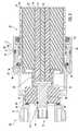
- FIG. 1is a perspective cutaway view of a connector installed on the end of a coaxial cable having a smooth outer conductor in accordance with the present invention.
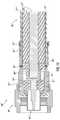
- FIG. 2is a longitudinal cross-sectional view of the connector of FIG. 1 .
- FIG. 3is a greatly enlarged cross sectional view of the insulator member of FIG. 1 .
- FIG. 4is an enlarged cross sectional view of the center contact of FIG. 1 .
- FIG. 5is a greatly enlarged cross sectional view of the rotation locking feature of the connector housing of FIG. 1 .
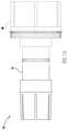
- FIG. 6is a perspective cutaway view of another embodiment of a connector installed on the end of a coaxial cable having a smooth outer conductor in accordance with the present invention.
- FIG. 7is a longitudinal cross-sectional view of the connector of FIG. 6 .
- FIG. 8is a greatly enlarged cross sectional view of the insulator member of FIG. 6 .
- FIG. 9is a longitudinal cross-sectional view of a further embodiment of a connector installed on the end of a coaxial cable having a smooth outer conductor in accordance with the present invention.
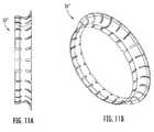
- FIG. 10is an enlarged cross-sectional view of the flexible ring of FIG. 9 .
- FIG. 11Ais a side view of the flexible ring of FIG. 9 .
- FIG. 11Bis a perspective view of the flexible ring of FIG. 9 .
- FIG. 12is a greatly enlarged cross sectional view of the grip ring of FIG. 9 .
- FIG. 13is a perspective view of a center contact that may be used with the connector of the present invention.
- FIG. 14is a longitudinal cross-sectional view of an additional embodiment of a connector installed on the end of a coaxial cable having a smooth outer conductor in accordance with the present invention.
- FIG. 15is a longitudinal cross-sectional view of a two-piece center contact that may be used with the connector of the present invention.
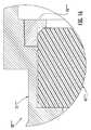
- FIG. 16is a greatly enlarged cross-sectional view of an alternative embodiment of the connector of the present invention.
- the coaxial cable 20comprises an inner conductor 24 , an outer conductor 21 , and a dielectric 23 therebetween.
- the inner conductor 24(which may comprise aluminum, copper, copper clad aluminum, or other suitable type of metal) is a hollow inner conductor with an inner conductor rod 26 , and an inner conductor dielectric 25 therebetween.
- the outer conductor 31is illustratively a smooth outer conductor with a flared end 53 , but could be a corrugated outer (helical or annular) conductor in other embodiments.
- the inner conductor 24may in some applications be a solid inner conductor.
- the dielectric 23may be a foam dielectric or other dielectric as known to those skilled in the art.
- the coaxial cable 20illustratively includes an outer insulation jacket 21 stripped back a distance so that outer end portions of the outer conductor 22 are exposed.
- the connector 30includes an externally threaded back nut 41 received within an internally threaded rearward end 34 of a connector housing 31 .
- the back nut 41may be internally threaded to receive an externally threaded connector housing 31 .
- the connector housing 31illustratively has a cylindrical shape.
- the back nut 41includes threads 44 to dig into the jacket 21 to securely attach the back nut to the coaxial cable 20 .
- threads 44are optional.
- a forward o-ring 37 and a rearward o-ring 43are illustratively provided to seal respective forward and rearward interfaces adjacent the back nut 41 to thereby reduce or prevents moisture ingress.
- An insulator member 45is securely received within the connector housing 31 and has a central opening defined therein.
- a center contact 46is positioned within the connector housing 31 .
- a shaft portion 47 of the center contact 46is rotatably received within the central opening of the insulator member 45 and defines a rotational joint 49 therewith.
- the shaft 47has a recess 51 therein defining an air gap with adjacent portions of the insulator member 45 at the rotational joint 49 .
- An open end portion 48 of the center contact 46extends rearwardly from the shaft portion 47 and securely receives the inner conductor 24 therein.
- teethmay extend radially inwardly from the inner diameter of the open end portion 48 to bite into the inner conductor 24 , thereby helping to reduce axial movement therebetween.
- the open end portion 48may have a diameter less than that of the inner conductor 24 so that it securely closes around the inner conductor 24 .
- the radially inner surface of the open end portion 48may optionally be knurled to increase friction with the inner conductor 24 (see FIG. 13 ).
- This arrangementadvantageously allows the connector housing 31 and insulator member 45 to rotate with respect to the center contact 46 , while the center contact remains stationary with respect to the inner conductor 24 , as the connector housing 31 and back nut 41 are rotatably engaged during installation of the connector 30 onto the coaxial cable 20 .
- Applicanthas found that relative rotation occurs between the center contact 46 and inner conductor 24 , and this, in turn, causes pieces of the inner conductor to chip off and accumulate between the center contact and inner conductor. This may reduce the diameter of the inner conductor 24 or even etch threads into the inner conductor. The presence of these chips may increase contact resistance or reduce contact pressure between the inner conductor 24 and the center contact 46 , causing increased signal degradation and IMD.
- a retaining projection 38which could be a barb or knurled barb, extends radially inwardly from the inner diameter of the connector housing 31 and bites into the insulator member 45 to not only restrain the insulator member from rearward axial movement within the connector housing, but also to help prevent relative rotation between the insulator member and the connector housing.
- An additional retaining projection 54extends radially outwardly from the outer diameter of the center contact 46 to restrain the insulator member 45 from forward axial movement within the connector hosing. As shown in FIG. 4 , the retaining projection 54 is a shoulder that does not bite into the insulator member 45 itself. It should also be appreciated that the connector housing 31 and insulator member 45 may spin freely, and need not be coupled to other portions of the connector 30 .
- the connector housing 31defines a ramp 32 to receive the outer conductor 22 thereagainst.
- the ramp 32illustratively has a knurled surface, although the skilled artisan will understand that other ramp surfaces may be used.
- An electrically conductive compressible coil spring 36compressibly clamps against the outer conductor 22 opposite the ramp 32 as the connector housing 31 and back nut 41 are engaged.
- the electrically conductive compressible coil spring 36illustratively has an axis coaxial with that of the connector housing 31 .
- This clampinghelps to provide an electrical connection between the outer conductor 22 and the ramp 32 by providing a constant contact pressure between the outer conductor and the ramp. By maintaining such a secure electrical connection, the IMD of signals traveling through the coaxial cable 20 may be reduced.
- the electrically conductive compressible coil spring 36advantageously maintains a sufficient clamping force on the outer conductor 22 even if the outer conductor changes shape or size due to thermal expansion or aluminum creep, for example, whereas an arrangement of two wedging surfaces to clamp the outer conductor might lose clamping force and contact pressure if the outer conductor were to change shape or size.
- the electrically conductive compressible coil spring 36allows the connector 30 to be used on a variety of coaxial cables with different thicknesses, and on a variety of coaxial cables with outer conductors having different thicknesses.
- the clamping provided by the electrically conductive compressible coil spring 36further reduces radial movement of the connector 30 about the coaxial cable 30 . That is, the electrically conductive compressible coil spring 36 acts as an anti-rotational device, such as a lock washer, to clamp the coaxial cable 20 between the connector housing 31 and back nut 41 and bites into the outer conductor 22 to reduce or prevent rotation of the connector 10 about the coaxial cable 30 .
- an anti-rotational devicesuch as a lock washer
- the ramp 32is angled such as to flare an end 53 of the outer conductor 22 as the coaxial cable 20 is inserted into the connector housing 31 . This advantageously reduces the preparation performed on the coaxial cable 20 before installation of the connector 30 . Cable preparation now merely includes cutting the coaxial cable end flush and trimming the jacket 21 back. As the coaxial cable 20 is inserted into the connector 30 and the connector housing 31 and back nut 41 are engaged, the ramp 32 wedges between the outer conductor 22 and dielectric 23 , thereby flaring the end 53 of the outer conductor.
- An additional insulator member 52is within the connector housing 31 for carrying the rearwardly extending open end 48 of the center contact 31 .
- the additional insulator member 52is positioned between the insulator member 45 and dielectric 23 of the coaxial cable 20 thereby restraining the insulator member from rearward axial movement and the coaxial cable from forward radial movement.
- the insulator member 45optionally comprises a hard, low friction material having a coefficient of friction of less than 0.7.
- polyoxymethyleneis a particularly advantageous material from which to construct the insulator member 45 .
- Other useful materials from which to construct the insulator member 45include polymethylpentene, polytetrafluoroethylene, an injection moldable blend of polyoxymethylene and polytetrafluoroethylene, or a cross linked polystyrene microwave plastic. Of course, those of skill in the art will appreciate that other suitable materials may be used.
- FIGS. 6-7Another embodiment of the connector 30 ′ is now described with respect to FIGS. 6-7 .
- the back nut 41 ′is internally threaded and receives an externally threaded rearward end 43 ′ of the connector housing.
- the insulator member 45 ′is rotatably received within the connector housing 31 ′, and securely receives the center contact 46 ′ in its central opening.
- an optional rotation locking projection 54 ′extends radially outwardly from the outer diameter of the center contact 46 ′ and bites into the insulator member 45 ′ to both prevent forward axial movement of the insulator member.
- a rotational joint 54 ′is defined between the insulator member 45 ′ and the connector housing 31 ′.
- the connector housing 31 ′may thus be rotated with respect to the insulator member 45 ′ and center contact 46 ′, which remains stationary with respect to the inner conductor 24 ′. As explained above, this helps to reduce the formation of chips between the center contact 46 ′ and the inner conductor 24 ′, thereby reducing IMD. It should be understood that in some applications, the insulator member 45 ′ may also rotate with respect to the center contact 46 .
- FIGS. 9-11A further embodiment of the connector 30 ′′ is now described with respect to FIGS. 9-11 .
- the outer conductor 22 ′′is not flared.
- the connector housing 31 ′′ and back nut 41 ′′are not threaded. Instead, a forward portion of the back nut 41 ′′ is received within a rearward portion of the connector housing 31 ′′.
- the electrically conductive flexible ring 55 ′′illustratively has a reverse S shape, although it may take other shapes in other applications.
- the electrically conductive flexible ring 55 ′′presses against both the inner diameter of the connector housing 31 ′′ and the outer conductor 22 ′′, creating a secure electrical connection therebetween.
- the electrically conductive flexible ring 55 ′′receives the outer conductor 31 ′′ therethrough, and defines a rotational joint therewith. To facilitate this rotational joint, both the inner and the outer diameter of the electrically conductive flexible ring 55 ′′ may be low friction.
- a grip ring 56 ′′is positioned in the back nut rearwardly of the electrically conductive flexible ring 55 ′′.
- the grip ring 56 ′′has a plurality of forward pointing teeth that bite into the outer conductor 22 ′′, helping to reduce or eliminate axial movement of the coaxial cable 20 ′′ in a rearward direction.
- the grip ring 56 ′′may define a rotational joint with the back nut 41 ′′.
- the grip ringmay have a low friction outer diameter. It should be appreciated that, in this embodiment, the connector hosing 31 ′′, back nut 41 ′′, insulator member 45 ′′, electrically conductive flexible ring 55 ′′, and grip ring 56 ′′ may rotate separately with respect to the coaxial cable 20 ′′ and/or with respect to each other.
- the grip ring 56 ′′has an optional rounded projection 57 ′′ extending outwardly from an outer diameter thereof. This rounded projection 57 ′′ engages the back nut 41 ′′, thereby reducing the contact area between the grip ring 56 ′′ and the back nut, enabling the grip ring to rotate easily thereabout.
- the center contact 31 ′′′′may be a two-piece center contact (see FIG. 15 ).
- the center contact 31 ′′′′comprises a forward portion 60 ′′′′ with a rearwardly facing projection 61 ′′.
- a rearward portion 62 ′′′′ of the center contact 31 ′′′′includes a forward facing recess 63 ′′′′ to receive the projection 61 ′′′′.
- the rearward portion 62 ′′′′includes the shaft 47 ′′′′ and the open end portion 48 ′′′′.
- the projection 61 ′′′′ and the recess 63 ′′′′may be threaded.
- the forward portion 60 ′′′′has a diameter greater than that of the shaft 47 ′′′′ to thereby capture the insulator member 45 ′′′′ between the forward portion and the open end portion 48 ′′′′. This helps to restrain the insulator member 45 ′′′′ from unwanted longitudinal movement.
- FIG. 14An additional embodiment of a connector 30 ′′′ for a coaxial cable 20 ′′′ is now described with reference to FIG. 14 .
- This connector 30 ′′′does not have a back nut. Rather, the connector housing 31 ′′′ housing received the coaxial cable 20 ′′′.
- Other elements of this embodiment not specifically mentionedare similar to those of the connector 30 described with reference to FIGS. 1-2 above and require no further discussion herein.
- an L-shaped insulator member locking feature 70 ′′′′′is positioned between the insulator member 45 ′′′′′ and the connector hosing 31 ′′′′′.
- This locking feature 70 ′′′′′helps reduce or prevent axial movement of the insulator member 45 ′′′′′ with respect to the connector hosing 31 ′′′′′.
- the locking feature 70 ′′′′′is illustratively constructed from metal, but may also be constructed from rubber, a polymer, or other suitable material.
- the locking feature 70 ′′′′′may be threadingly received by the connector housing 31 ′′′′′ or may be pressed into the connector hosing during assembly.
- Other elements of this embodiment not specifically mentionedare similar to those of the connector 30 described with reference to FIGS. 1-2 above and require no further discussion herein.
- connectors 30 for coaxial cables 20may be found in co-pending application, CONNECTOR FOR COAXIAL CABLE HAVING ROTATIONAL JOINT BETWEEN INSULATOR MEMBER AND CENTER CONTACT AND ASSOCIATED METHODS, Ser. No. 12/706,135, the entire disclosure of which is hereby incorporated by reference.
Landscapes
- Coupling Device And Connection With Printed Circuit (AREA)
Abstract
Description
Claims (16)
Priority Applications (4)
| Application Number | Priority Date | Filing Date | Title |
|---|---|---|---|
| US12/706,147US8206176B2 (en) | 2010-02-16 | 2010-02-16 | Connector for coaxial cable having rotational joint between insulator member and connector housing and associated methods |
| CN2011800164909ACN102823078A (en) | 2010-02-16 | 2011-02-16 | Connector for coaxial cable having rotational joint between insulator member and connector housing and associated methods |
| PCT/US2011/025090WO2011103195A1 (en) | 2010-02-16 | 2011-02-16 | Connector for coaxial cable having rotational joint between insulator member and connector housing and associated methods |
| EP11705780AEP2537211A1 (en) | 2010-02-16 | 2011-02-16 | Connector for coaxial cable having rotational joint between insulator member and connector housing and associated methods |
Applications Claiming Priority (1)
| Application Number | Priority Date | Filing Date | Title |
|---|---|---|---|
| US12/706,147US8206176B2 (en) | 2010-02-16 | 2010-02-16 | Connector for coaxial cable having rotational joint between insulator member and connector housing and associated methods |
Publications (2)
| Publication Number | Publication Date |
|---|---|
| US20110201230A1 US20110201230A1 (en) | 2011-08-18 |
| US8206176B2true US8206176B2 (en) | 2012-06-26 |
Family
ID=43821807
Family Applications (1)
| Application Number | Title | Priority Date | Filing Date |
|---|---|---|---|
| US12/706,147Expired - Fee RelatedUS8206176B2 (en) | 2010-02-16 | 2010-02-16 | Connector for coaxial cable having rotational joint between insulator member and connector housing and associated methods |
Country Status (4)
| Country | Link |
|---|---|
| US (1) | US8206176B2 (en) |
| EP (1) | EP2537211A1 (en) |
| CN (1) | CN102823078A (en) |
| WO (1) | WO2011103195A1 (en) |
Cited By (21)
| Publication number | Priority date | Publication date | Assignee | Title |
|---|---|---|---|---|
| US20120045933A1 (en)* | 2010-08-20 | 2012-02-23 | Pct International, Inc. | Coaxial cable connectors and associated washers |
| US20130023151A1 (en)* | 2011-05-26 | 2013-01-24 | Belden Inc. | Coaxial cable connector with conductive seal |
| US20130164981A1 (en)* | 2011-12-27 | 2013-06-27 | Hon Hai Precision Industry Co., Ltd. | Connector with shielding device and method for manufacuring connector |
| US20130203287A1 (en)* | 2012-02-06 | 2013-08-08 | John Mezzalingua Associates, Inc. | Port assembly connector for engaging a coaxial cable and an outer conductor |
| US20140004721A1 (en)* | 2012-06-29 | 2014-01-02 | Corning Gilbert, Inc. | Multi-sectional insulator for coaxial connector |
| US8801448B2 (en) | 2009-05-22 | 2014-08-12 | Ppc Broadband, Inc. | Coaxial cable connector having electrical continuity structure |
| US20140273622A1 (en)* | 2013-03-15 | 2014-09-18 | Fct Electronics Lp | High-Temperature RF Connector |
| US8858251B2 (en) | 2010-11-11 | 2014-10-14 | Ppc Broadband, Inc. | Connector having a coupler-body continuity member |
| US9009960B2 (en) | 2013-01-25 | 2015-04-21 | Commscope Technologies Llc | Method of manufacturing a curved transition surface of an inner contact |
| US9017101B2 (en) | 2011-03-30 | 2015-04-28 | Ppc Broadband, Inc. | Continuity maintaining biasing member |
| US9028276B2 (en) | 2011-12-06 | 2015-05-12 | Pct International, Inc. | Coaxial cable continuity device |
| US20150255917A1 (en)* | 2014-03-07 | 2015-09-10 | Chant Sincere Co., Ltd. | Plug connector |
| US9240636B2 (en) | 2011-05-19 | 2016-01-19 | Pct International, Inc. | Coaxial cable connector having a coupling nut and a conductive insert with a flange |
| US9490052B2 (en) | 2012-06-29 | 2016-11-08 | Corning Gilbert, Inc. | Tubular insulator for coaxial connector |
| US9570845B2 (en) | 2009-05-22 | 2017-02-14 | Ppc Broadband, Inc. | Connector having a continuity member operable in a radial direction |
| US9595776B2 (en) | 2011-03-30 | 2017-03-14 | Ppc Broadband, Inc. | Connector producing a biasing force |
| US9711917B2 (en) | 2011-05-26 | 2017-07-18 | Ppc Broadband, Inc. | Band spring continuity member for coaxial cable connector |
| US9871315B1 (en)* | 2017-04-05 | 2018-01-16 | Din Yi Industrial Co., Ltd. | Electrical connector for connection to a transmission connector on a device |
| US20180083401A1 (en)* | 2016-09-20 | 2018-03-22 | Commscope Technologies Llc | Right angle coaxial connector assembly |
| US10439302B2 (en) | 2017-06-08 | 2019-10-08 | Pct International, Inc. | Connecting device for connecting and grounding coaxial cable connectors |
| US10938093B2 (en) | 2019-07-16 | 2021-03-02 | Motorola Solutions, Inc. | Portable communication device and antenna device with robust rotational attachment |
Families Citing this family (10)
| Publication number | Priority date | Publication date | Assignee | Title |
|---|---|---|---|---|
| US20110201232A1 (en)* | 2010-02-16 | 2011-08-18 | Andrew Llc | Connector for coaxial cable having rotational joint between insulator member and center contact and associated methods |
| DE102010014981A1 (en)* | 2010-04-14 | 2011-10-20 | Pfisterer Kontaktsysteme Gmbh | Device for electrically connecting a cable, in particular plug connection part |
| US9306346B2 (en) | 2013-06-17 | 2016-04-05 | Commscope Technologies Llc | Coaxial cable and connector with capacitive coupling |
| CN104993265A (en)* | 2015-06-30 | 2015-10-21 | 张家港金海港电线电缆有限公司 | Cable connecting device |
| CN115799928A (en)* | 2018-03-14 | 2023-03-14 | 康普技术有限责任公司 | Coaxial Offset T Connector |
| CN109713515B (en)* | 2018-12-25 | 2020-09-25 | 杭州航天电子技术有限公司 | Environment-resistant rotatable electric connector switching mechanism |
| CN111463598A (en)* | 2019-01-22 | 2020-07-28 | 罗森伯格亚太电子有限公司 | Radio frequency coaxial elastic connector |
| CN109980468B (en)* | 2019-03-29 | 2024-08-13 | 北科电子科技(苏州)有限公司 | Integral type SMA connector |
| CN110867698B (en)* | 2019-12-24 | 2025-09-16 | 苏州正北连接技术股份有限公司 | Rotary connector with high-voltage interlocking structure |
| CN115173106A (en)* | 2022-07-22 | 2022-10-11 | 中车青岛四方机车车辆股份有限公司 | Connector terminal assembly and connector |
Citations (19)
| Publication number | Priority date | Publication date | Assignee | Title |
|---|---|---|---|---|
| US3786376A (en)* | 1970-12-18 | 1974-01-15 | Ball Brothers Res Corp | Self-lubricated rotary joint |
| US4326769A (en) | 1980-04-21 | 1982-04-27 | Litton Systems, Inc. | Rotary coaxial assembly |
| US5137470A (en)* | 1991-06-04 | 1992-08-11 | Andrew Corporation | Connector for coaxial cable having a helically corrugated inner conductor |
| US5354217A (en)* | 1993-06-10 | 1994-10-11 | Andrew Corporation | Lightweight connector for a coaxial cable |
| EP0818854A1 (en) | 1996-07-08 | 1998-01-14 | Amphenol Corporation | Electrical connector and cable termination system |
| US5795188A (en) | 1996-03-28 | 1998-08-18 | Andrew Corporation | Connector kit for a coaxial cable, method of attachment and the resulting assembly |
| US6561848B1 (en)* | 2002-01-18 | 2003-05-13 | Adc Telecommunications, Inc. | Triaxial connector adapter and method |
| US6575786B1 (en)* | 2002-01-18 | 2003-06-10 | Adc Telecommunications, Inc. | Triaxial connector and method |
| US6592403B2 (en) | 2001-11-09 | 2003-07-15 | Corning Gilbert Inc. | Coaxial connector swivel interface |
| US20040266259A1 (en) | 2003-06-26 | 2004-12-30 | Moseley Andrew P. | Coaxial cable connector having anti-rotational features |
| US7011546B2 (en) | 2003-09-09 | 2006-03-14 | Commscope Properties, Llc | Coaxial connector with enhanced insulator member and associated methods |
| US7011553B2 (en) | 2003-10-30 | 2006-03-14 | Japan Aviation Electronics Industry, Limited | Cable connector having a retainer which serves to hold a cable, to protect a connecting portion, and to prevent undesirable releasing of a contact |
| US7077700B2 (en) | 2004-12-20 | 2006-07-18 | Corning Gilbert Inc. | Coaxial connector with back nut clamping ring |
| US7131858B1 (en)* | 2004-12-21 | 2006-11-07 | Yazaki North America, Inc. | Angled coaxial cable connector for mating axis termination method |
| US7171753B2 (en)* | 2004-06-15 | 2007-02-06 | Andrew Corporation | Multi-cable jacket removal tool |
| US7197821B2 (en)* | 2002-01-18 | 2007-04-03 | Adc Telecommunications, Inc. | Triaxial connector including cable clamp |
| US7435135B2 (en)* | 2007-02-08 | 2008-10-14 | Andrew Corporation | Annular corrugated coaxial cable connector with polymeric spring finger nut |
| US20100041271A1 (en) | 2008-08-14 | 2010-02-18 | Andrew Llc | Multi-shot Coaxial Connector and Method of Manufacture |
| US20100126011A1 (en)* | 2008-11-24 | 2010-05-27 | Andrew, Llc, State/Country Of Incorporation: North Carolina | Flaring coaxial cable end preparation tool and associated methods |
- 2010
- 2010-02-16USUS12/706,147patent/US8206176B2/ennot_activeExpired - Fee Related
- 2011
- 2011-02-16WOPCT/US2011/025090patent/WO2011103195A1/enactiveApplication Filing
- 2011-02-16CNCN2011800164909Apatent/CN102823078A/enactivePending
- 2011-02-16EPEP11705780Apatent/EP2537211A1/ennot_activeWithdrawn
Patent Citations (22)
| Publication number | Priority date | Publication date | Assignee | Title |
|---|---|---|---|---|
| US3786376A (en)* | 1970-12-18 | 1974-01-15 | Ball Brothers Res Corp | Self-lubricated rotary joint |
| US4326769A (en) | 1980-04-21 | 1982-04-27 | Litton Systems, Inc. | Rotary coaxial assembly |
| US5137470A (en)* | 1991-06-04 | 1992-08-11 | Andrew Corporation | Connector for coaxial cable having a helically corrugated inner conductor |
| US5354217A (en)* | 1993-06-10 | 1994-10-11 | Andrew Corporation | Lightweight connector for a coaxial cable |
| US5795188A (en) | 1996-03-28 | 1998-08-18 | Andrew Corporation | Connector kit for a coaxial cable, method of attachment and the resulting assembly |
| EP0818854A1 (en) | 1996-07-08 | 1998-01-14 | Amphenol Corporation | Electrical connector and cable termination system |
| US6592403B2 (en) | 2001-11-09 | 2003-07-15 | Corning Gilbert Inc. | Coaxial connector swivel interface |
| US6561848B1 (en)* | 2002-01-18 | 2003-05-13 | Adc Telecommunications, Inc. | Triaxial connector adapter and method |
| US6575786B1 (en)* | 2002-01-18 | 2003-06-10 | Adc Telecommunications, Inc. | Triaxial connector and method |
| US7197821B2 (en)* | 2002-01-18 | 2007-04-03 | Adc Telecommunications, Inc. | Triaxial connector including cable clamp |
| US7281948B2 (en)* | 2002-01-18 | 2007-10-16 | Adc Telecommunications, Inc. | Triaxial connector and method |
| US20060063426A1 (en)* | 2002-01-18 | 2006-03-23 | Adc Telecommunications, Inc., | Triaxial connector adapter and method |
| US20070175027A1 (en)* | 2002-01-18 | 2007-08-02 | Adc Telecommunications, Inc. | Triaxial connector including cable clamp |
| US20040266259A1 (en) | 2003-06-26 | 2004-12-30 | Moseley Andrew P. | Coaxial cable connector having anti-rotational features |
| US7011546B2 (en) | 2003-09-09 | 2006-03-14 | Commscope Properties, Llc | Coaxial connector with enhanced insulator member and associated methods |
| US7011553B2 (en) | 2003-10-30 | 2006-03-14 | Japan Aviation Electronics Industry, Limited | Cable connector having a retainer which serves to hold a cable, to protect a connecting portion, and to prevent undesirable releasing of a contact |
| US7171753B2 (en)* | 2004-06-15 | 2007-02-06 | Andrew Corporation | Multi-cable jacket removal tool |
| US7077700B2 (en) | 2004-12-20 | 2006-07-18 | Corning Gilbert Inc. | Coaxial connector with back nut clamping ring |
| US7131858B1 (en)* | 2004-12-21 | 2006-11-07 | Yazaki North America, Inc. | Angled coaxial cable connector for mating axis termination method |
| US7435135B2 (en)* | 2007-02-08 | 2008-10-14 | Andrew Corporation | Annular corrugated coaxial cable connector with polymeric spring finger nut |
| US20100041271A1 (en) | 2008-08-14 | 2010-02-18 | Andrew Llc | Multi-shot Coaxial Connector and Method of Manufacture |
| US20100126011A1 (en)* | 2008-11-24 | 2010-05-27 | Andrew, Llc, State/Country Of Incorporation: North Carolina | Flaring coaxial cable end preparation tool and associated methods |
Cited By (49)
| Publication number | Priority date | Publication date | Assignee | Title |
|---|---|---|---|---|
| US9419389B2 (en) | 2009-05-22 | 2016-08-16 | Ppc Broadband, Inc. | Coaxial cable connector having electrical continuity member |
| US9660398B2 (en) | 2009-05-22 | 2017-05-23 | Ppc Broadband, Inc. | Coaxial cable connector having electrical continuity member |
| US9570845B2 (en) | 2009-05-22 | 2017-02-14 | Ppc Broadband, Inc. | Connector having a continuity member operable in a radial direction |
| US9496661B2 (en) | 2009-05-22 | 2016-11-15 | Ppc Broadband, Inc. | Coaxial cable connector having electrical continuity member |
| US10862251B2 (en) | 2009-05-22 | 2020-12-08 | Ppc Broadband, Inc. | Coaxial cable connector having an electrical grounding portion |
| US12244108B2 (en) | 2009-05-22 | 2025-03-04 | Ppc Broadband, Inc. | Ground portion for maintaining a ground path in a coaxial cable connector |
| US10931068B2 (en) | 2009-05-22 | 2021-02-23 | Ppc Broadband, Inc. | Connector having a grounding member operable in a radial direction |
| US8801448B2 (en) | 2009-05-22 | 2014-08-12 | Ppc Broadband, Inc. | Coaxial cable connector having electrical continuity structure |
| US20120045933A1 (en)* | 2010-08-20 | 2012-02-23 | Pct International, Inc. | Coaxial cable connectors and associated washers |
| US8579658B2 (en)* | 2010-08-20 | 2013-11-12 | Timothy L. Youtsey | Coaxial cable connectors with washers for preventing separation of mated connectors |
| US8858251B2 (en) | 2010-11-11 | 2014-10-14 | Ppc Broadband, Inc. | Connector having a coupler-body continuity member |
| US8915754B2 (en) | 2010-11-11 | 2014-12-23 | Ppc Broadband, Inc. | Connector having a coupler-body continuity member |
| US8920182B2 (en) | 2010-11-11 | 2014-12-30 | Ppc Broadband, Inc. | Connector having a coupler-body continuity member |
| US8920192B2 (en) | 2010-11-11 | 2014-12-30 | Ppc Broadband, Inc. | Connector having a coupler-body continuity member |
| US11811184B2 (en) | 2011-03-30 | 2023-11-07 | Ppc Broadband, Inc. | Connector producing a biasing force |
| US10559898B2 (en) | 2011-03-30 | 2020-02-11 | Ppc Broadband, Inc. | Connector producing a biasing force |
| US9660360B2 (en) | 2011-03-30 | 2017-05-23 | Ppc Broadband, Inc. | Connector producing a biasing force |
| US9608345B2 (en) | 2011-03-30 | 2017-03-28 | Ppc Broadband, Inc. | Continuity maintaining biasing member |
| US9595776B2 (en) | 2011-03-30 | 2017-03-14 | Ppc Broadband, Inc. | Connector producing a biasing force |
| US9017101B2 (en) | 2011-03-30 | 2015-04-28 | Ppc Broadband, Inc. | Continuity maintaining biasing member |
| US10186790B2 (en) | 2011-03-30 | 2019-01-22 | Ppc Broadband, Inc. | Connector producing a biasing force |
| US9240636B2 (en) | 2011-05-19 | 2016-01-19 | Pct International, Inc. | Coaxial cable connector having a coupling nut and a conductive insert with a flange |
| US9711917B2 (en) | 2011-05-26 | 2017-07-18 | Ppc Broadband, Inc. | Band spring continuity member for coaxial cable connector |
| US11283226B2 (en) | 2011-05-26 | 2022-03-22 | Ppc Broadband, Inc. | Grounding member for coaxial cable connector |
| US9203167B2 (en)* | 2011-05-26 | 2015-12-01 | Ppc Broadband, Inc. | Coaxial cable connector with conductive seal |
| US20130023151A1 (en)* | 2011-05-26 | 2013-01-24 | Belden Inc. | Coaxial cable connector with conductive seal |
| US9577391B2 (en) | 2011-12-06 | 2017-02-21 | Pct International, Inc. | Coaxial cable continuity device |
| US9768566B2 (en) | 2011-12-06 | 2017-09-19 | Pct International, Inc. | Coaxial cable continuity device |
| US9028276B2 (en) | 2011-12-06 | 2015-05-12 | Pct International, Inc. | Coaxial cable continuity device |
| US8711577B2 (en)* | 2011-12-27 | 2014-04-29 | Hong Fu Jin Precision Industry (Wuhan) Co., Ltd. | Connector with shielding device and method for manufacturing connector |
| US20130164981A1 (en)* | 2011-12-27 | 2013-06-27 | Hon Hai Precision Industry Co., Ltd. | Connector with shielding device and method for manufacuring connector |
| US20130203287A1 (en)* | 2012-02-06 | 2013-08-08 | John Mezzalingua Associates, Inc. | Port assembly connector for engaging a coaxial cable and an outer conductor |
| US9017102B2 (en)* | 2012-02-06 | 2015-04-28 | John Mezzalingua Associates, LLC | Port assembly connector for engaging a coaxial cable and an outer conductor |
| US9490052B2 (en) | 2012-06-29 | 2016-11-08 | Corning Gilbert, Inc. | Tubular insulator for coaxial connector |
| US20140004721A1 (en)* | 2012-06-29 | 2014-01-02 | Corning Gilbert, Inc. | Multi-sectional insulator for coaxial connector |
| US9589710B2 (en)* | 2012-06-29 | 2017-03-07 | Corning Optical Communications Rf Llc | Multi-sectional insulator for coaxial connector |
| US9419351B2 (en) | 2013-01-25 | 2016-08-16 | Commscope Technologies Llc | Curved transition surface inner contact |
| US9009960B2 (en) | 2013-01-25 | 2015-04-21 | Commscope Technologies Llc | Method of manufacturing a curved transition surface of an inner contact |
| US20140273622A1 (en)* | 2013-03-15 | 2014-09-18 | Fct Electronics Lp | High-Temperature RF Connector |
| US9276332B2 (en)* | 2013-03-15 | 2016-03-01 | Fct, Us L.L.C. | High-temperature RF connector |
| US9490573B2 (en)* | 2014-03-07 | 2016-11-08 | Chant Sincere Co., Ltd. | Electrical plug connector with double casing |
| US20150255917A1 (en)* | 2014-03-07 | 2015-09-10 | Chant Sincere Co., Ltd. | Plug connector |
| CN109661754A (en)* | 2016-09-20 | 2019-04-19 | 康普技术有限责任公司 | Right Angle Coaxial Connector Assembly |
| US10186817B2 (en)* | 2016-09-20 | 2019-01-22 | Commscope Technologies Llc | Right angle coaxial connector assembly |
| US20180083401A1 (en)* | 2016-09-20 | 2018-03-22 | Commscope Technologies Llc | Right angle coaxial connector assembly |
| US9871315B1 (en)* | 2017-04-05 | 2018-01-16 | Din Yi Industrial Co., Ltd. | Electrical connector for connection to a transmission connector on a device |
| US10439302B2 (en) | 2017-06-08 | 2019-10-08 | Pct International, Inc. | Connecting device for connecting and grounding coaxial cable connectors |
| US10855003B2 (en) | 2017-06-08 | 2020-12-01 | Pct International, Inc. | Connecting device for connecting and grounding coaxial cable connectors |
| US10938093B2 (en) | 2019-07-16 | 2021-03-02 | Motorola Solutions, Inc. | Portable communication device and antenna device with robust rotational attachment |
Also Published As
| Publication number | Publication date |
|---|---|
| CN102823078A (en) | 2012-12-12 |
| US20110201230A1 (en) | 2011-08-18 |
| WO2011103195A1 (en) | 2011-08-25 |
| EP2537211A1 (en) | 2012-12-26 |
Similar Documents
| Publication | Publication Date | Title |
|---|---|---|
| US8206176B2 (en) | Connector for coaxial cable having rotational joint between insulator member and connector housing and associated methods | |
| US20110201232A1 (en) | Connector for coaxial cable having rotational joint between insulator member and center contact and associated methods | |
| US7632143B1 (en) | Connector with positive stop and compressible ring for coaxial cable and associated methods | |
| US7635283B1 (en) | Connector with retaining ring for coaxial cable and associated methods | |
| US7857661B1 (en) | Coaxial cable connector having jacket gripping ferrule and associated methods | |
| US7011546B2 (en) | Coaxial connector with enhanced insulator member and associated methods | |
| US7785144B1 (en) | Connector with positive stop for coaxial cable and associated methods | |
| US7931499B2 (en) | Connector including flexible fingers and associated methods | |
| KR101062521B1 (en) | Coaxial connector with clamping slopes and method for manufacturing same | |
| US9455507B2 (en) | Coaxial cable connector having a continuity element | |
| US8449311B2 (en) | Locking audio plug | |
| US9270046B2 (en) | Seal for helical corrugated outer conductor | |
| HK1090178B (en) | Coaxial connector with enhanced insulator member and associated method |
Legal Events
| Date | Code | Title | Description |
|---|---|---|---|
| AS | Assignment | Owner name:ANDREW LLC, NORTH CAROLINA Free format text:ASSIGNMENT OF ASSIGNORS INTEREST;ASSIGNOR:ISLAM, NAHID;REEL/FRAME:023939/0664 Effective date:20100129 | |
| AS | Assignment | Owner name:JPMORGAN CHASE BANK, N.A., AS COLLATERAL AGENT, NE Free format text:SECURITY AGREEMENT;ASSIGNORS:ALLEN TELECOM LLC, A DELAWARE LLC;ANDREW LLC, A DELAWARE LLC;COMMSCOPE, INC. OF NORTH CAROLINA, A NORTH CAROLINA CORPORATION;REEL/FRAME:026276/0363 Effective date:20110114 | |
| AS | Assignment | Owner name:JPMORGAN CHASE BANK, N.A., AS COLLATERAL AGENT, NE Free format text:SECURITY AGREEMENT;ASSIGNORS:ALLEN TELECOM LLC, A DELAWARE LLC;ANDREW LLC, A DELAWARE LLC;COMMSCOPE, INC OF NORTH CAROLINA, A NORTH CAROLINA CORPORATION;REEL/FRAME:026272/0543 Effective date:20110114 | |
| STCF | Information on status: patent grant | Free format text:PATENTED CASE | |
| AS | Assignment | Owner name:COMMSCOPE TECHNOLOGIES LLC, NORTH CAROLINA Free format text:CHANGE OF NAME;ASSIGNOR:ANDREW LLC;REEL/FRAME:035286/0001 Effective date:20150301 | |
| AS | Assignment | Owner name:WILMINGTON TRUST, NATIONAL ASSOCIATION, AS COLLATERAL AGENT, CONNECTICUT Free format text:SECURITY INTEREST;ASSIGNORS:ALLEN TELECOM LLC;COMMSCOPE TECHNOLOGIES LLC;COMMSCOPE, INC. OF NORTH CAROLINA;AND OTHERS;REEL/FRAME:036201/0283 Effective date:20150611 Owner name:WILMINGTON TRUST, NATIONAL ASSOCIATION, AS COLLATE Free format text:SECURITY INTEREST;ASSIGNORS:ALLEN TELECOM LLC;COMMSCOPE TECHNOLOGIES LLC;COMMSCOPE, INC. OF NORTH CAROLINA;AND OTHERS;REEL/FRAME:036201/0283 Effective date:20150611 | |
| FPAY | Fee payment | Year of fee payment:4 | |
| AS | Assignment | Owner name:COMMSCOPE TECHNOLOGIES LLC, NORTH CAROLINA Free format text:RELEASE OF SECURITY INTEREST PATENTS (RELEASES RF 036201/0283);ASSIGNOR:WILMINGTON TRUST, NATIONAL ASSOCIATION;REEL/FRAME:042126/0434 Effective date:20170317 Owner name:ALLEN TELECOM LLC, NORTH CAROLINA Free format text:RELEASE OF SECURITY INTEREST PATENTS (RELEASES RF 036201/0283);ASSIGNOR:WILMINGTON TRUST, NATIONAL ASSOCIATION;REEL/FRAME:042126/0434 Effective date:20170317 Owner name:REDWOOD SYSTEMS, INC., NORTH CAROLINA Free format text:RELEASE OF SECURITY INTEREST PATENTS (RELEASES RF 036201/0283);ASSIGNOR:WILMINGTON TRUST, NATIONAL ASSOCIATION;REEL/FRAME:042126/0434 Effective date:20170317 Owner name:COMMSCOPE, INC. OF NORTH CAROLINA, NORTH CAROLINA Free format text:RELEASE OF SECURITY INTEREST PATENTS (RELEASES RF 036201/0283);ASSIGNOR:WILMINGTON TRUST, NATIONAL ASSOCIATION;REEL/FRAME:042126/0434 Effective date:20170317 | |
| AS | Assignment | Owner name:REDWOOD SYSTEMS, INC., NORTH CAROLINA Free format text:RELEASE BY SECURED PARTY;ASSIGNOR:JPMORGAN CHASE BANK, N.A.;REEL/FRAME:048840/0001 Effective date:20190404 Owner name:COMMSCOPE, INC. OF NORTH CAROLINA, NORTH CAROLINA Free format text:RELEASE BY SECURED PARTY;ASSIGNOR:JPMORGAN CHASE BANK, N.A.;REEL/FRAME:048840/0001 Effective date:20190404 Owner name:ALLEN TELECOM LLC, ILLINOIS Free format text:RELEASE BY SECURED PARTY;ASSIGNOR:JPMORGAN CHASE BANK, N.A.;REEL/FRAME:048840/0001 Effective date:20190404 Owner name:COMMSCOPE TECHNOLOGIES LLC, NORTH CAROLINA Free format text:RELEASE BY SECURED PARTY;ASSIGNOR:JPMORGAN CHASE BANK, N.A.;REEL/FRAME:048840/0001 Effective date:20190404 Owner name:ANDREW LLC, NORTH CAROLINA Free format text:RELEASE BY SECURED PARTY;ASSIGNOR:JPMORGAN CHASE BANK, N.A.;REEL/FRAME:048840/0001 Effective date:20190404 Owner name:COMMSCOPE TECHNOLOGIES LLC, NORTH CAROLINA Free format text:RELEASE BY SECURED PARTY;ASSIGNOR:JPMORGAN CHASE BANK, N.A.;REEL/FRAME:049260/0001 Effective date:20190404 Owner name:ANDREW LLC, NORTH CAROLINA Free format text:RELEASE BY SECURED PARTY;ASSIGNOR:JPMORGAN CHASE BANK, N.A.;REEL/FRAME:049260/0001 Effective date:20190404 Owner name:ALLEN TELECOM LLC, ILLINOIS Free format text:RELEASE BY SECURED PARTY;ASSIGNOR:JPMORGAN CHASE BANK, N.A.;REEL/FRAME:049260/0001 Effective date:20190404 Owner name:REDWOOD SYSTEMS, INC., NORTH CAROLINA Free format text:RELEASE BY SECURED PARTY;ASSIGNOR:JPMORGAN CHASE BANK, N.A.;REEL/FRAME:049260/0001 Effective date:20190404 Owner name:COMMSCOPE, INC. OF NORTH CAROLINA, NORTH CAROLINA Free format text:RELEASE BY SECURED PARTY;ASSIGNOR:JPMORGAN CHASE BANK, N.A.;REEL/FRAME:049260/0001 Effective date:20190404 | |
| AS | Assignment | Owner name:JPMORGAN CHASE BANK, N.A., NEW YORK Free format text:ABL SECURITY AGREEMENT;ASSIGNORS:COMMSCOPE, INC. OF NORTH CAROLINA;COMMSCOPE TECHNOLOGIES LLC;ARRIS ENTERPRISES LLC;AND OTHERS;REEL/FRAME:049892/0396 Effective date:20190404 Owner name:WILMINGTON TRUST, NATIONAL ASSOCIATION, AS COLLATE Free format text:PATENT SECURITY AGREEMENT;ASSIGNOR:COMMSCOPE TECHNOLOGIES LLC;REEL/FRAME:049892/0051 Effective date:20190404 Owner name:JPMORGAN CHASE BANK, N.A., NEW YORK Free format text:TERM LOAN SECURITY AGREEMENT;ASSIGNORS:COMMSCOPE, INC. OF NORTH CAROLINA;COMMSCOPE TECHNOLOGIES LLC;ARRIS ENTERPRISES LLC;AND OTHERS;REEL/FRAME:049905/0504 Effective date:20190404 Owner name:WILMINGTON TRUST, NATIONAL ASSOCIATION, AS COLLATERAL AGENT, CONNECTICUT Free format text:PATENT SECURITY AGREEMENT;ASSIGNOR:COMMSCOPE TECHNOLOGIES LLC;REEL/FRAME:049892/0051 Effective date:20190404 | |
| MAFP | Maintenance fee payment | Free format text:PAYMENT OF MAINTENANCE FEE, 8TH YEAR, LARGE ENTITY (ORIGINAL EVENT CODE: M1552); ENTITY STATUS OF PATENT OWNER: LARGE ENTITY Year of fee payment:8 | |
| AS | Assignment | Owner name:WILMINGTON TRUST, DELAWARE Free format text:SECURITY INTEREST;ASSIGNORS:ARRIS SOLUTIONS, INC.;ARRIS ENTERPRISES LLC;COMMSCOPE TECHNOLOGIES LLC;AND OTHERS;REEL/FRAME:060752/0001 Effective date:20211115 | |
| FEPP | Fee payment procedure | Free format text:MAINTENANCE FEE REMINDER MAILED (ORIGINAL EVENT CODE: REM.); ENTITY STATUS OF PATENT OWNER: LARGE ENTITY | |
| LAPS | Lapse for failure to pay maintenance fees | Free format text:PATENT EXPIRED FOR FAILURE TO PAY MAINTENANCE FEES (ORIGINAL EVENT CODE: EXP.); ENTITY STATUS OF PATENT OWNER: LARGE ENTITY | |
| STCH | Information on status: patent discontinuation | Free format text:PATENT EXPIRED DUE TO NONPAYMENT OF MAINTENANCE FEES UNDER 37 CFR 1.362 | |
| FP | Lapsed due to failure to pay maintenance fee | Effective date:20240626 | |
| AS | Assignment | Owner name:RUCKUS WIRELESS, LLC (F/K/A RUCKUS WIRELESS, INC.), NORTH CAROLINA Free format text:RELEASE OF SECURITY INTEREST AT REEL/FRAME 049905/0504;ASSIGNOR:JPMORGAN CHASE BANK, N.A., AS COLLATERAL AGENT;REEL/FRAME:071477/0255 Effective date:20241217 Owner name:COMMSCOPE TECHNOLOGIES LLC, NORTH CAROLINA Free format text:RELEASE OF SECURITY INTEREST AT REEL/FRAME 049905/0504;ASSIGNOR:JPMORGAN CHASE BANK, N.A., AS COLLATERAL AGENT;REEL/FRAME:071477/0255 Effective date:20241217 Owner name:COMMSCOPE, INC. OF NORTH CAROLINA, NORTH CAROLINA Free format text:RELEASE OF SECURITY INTEREST AT REEL/FRAME 049905/0504;ASSIGNOR:JPMORGAN CHASE BANK, N.A., AS COLLATERAL AGENT;REEL/FRAME:071477/0255 Effective date:20241217 Owner name:ARRIS SOLUTIONS, INC., NORTH CAROLINA Free format text:RELEASE OF SECURITY INTEREST AT REEL/FRAME 049905/0504;ASSIGNOR:JPMORGAN CHASE BANK, N.A., AS COLLATERAL AGENT;REEL/FRAME:071477/0255 Effective date:20241217 Owner name:ARRIS TECHNOLOGY, INC., NORTH CAROLINA Free format text:RELEASE OF SECURITY INTEREST AT REEL/FRAME 049905/0504;ASSIGNOR:JPMORGAN CHASE BANK, N.A., AS COLLATERAL AGENT;REEL/FRAME:071477/0255 Effective date:20241217 Owner name:ARRIS ENTERPRISES LLC (F/K/A ARRIS ENTERPRISES, INC.), NORTH CAROLINA Free format text:RELEASE OF SECURITY INTEREST AT REEL/FRAME 049905/0504;ASSIGNOR:JPMORGAN CHASE BANK, N.A., AS COLLATERAL AGENT;REEL/FRAME:071477/0255 Effective date:20241217 |