US8205991B2 - Method of eye registration for optical coherence tomography - Google Patents
Method of eye registration for optical coherence tomographyDownload PDFInfo
- Publication number
- US8205991B2 US8205991B2US12/423,757US42375709AUS8205991B2US 8205991 B2US8205991 B2US 8205991B2US 42375709 AUS42375709 AUS 42375709AUS 8205991 B2US8205991 B2US 8205991B2
- Authority
- US
- United States
- Prior art keywords
- image
- images
- scan
- scans
- feature
- Prior art date
- Legal status (The legal status is an assumption and is not a legal conclusion. Google has not performed a legal analysis and makes no representation as to the accuracy of the status listed.)
- Active, expires
Links
- 238000000034methodMethods0.000titleclaimsabstractdescription59
- 238000012014optical coherence tomographyMethods0.000titleclaimsdescription54
- 230000002207retinal effectEffects0.000claimsdescription19
- 238000012545processingMethods0.000claimsdescription11
- 210000001519tissueAnatomy0.000claimsdescription8
- 210000003583retinal pigment epitheliumAnatomy0.000claimsdescription6
- 238000002310reflectometryMethods0.000claimsdescription5
- 238000005259measurementMethods0.000claimsdescription4
- 238000001514detection methodMethods0.000claimsdescription3
- 238000009499grossingMethods0.000claimsdescription2
- 239000012528membraneSubstances0.000claimsdescription2
- 210000004126nerve fiberAnatomy0.000claimsdescription2
- 210000004204blood vesselAnatomy0.000description7
- 208000010412GlaucomaDiseases0.000description6
- 238000004458analytical methodMethods0.000description6
- 238000006073displacement reactionMethods0.000description6
- 208000038015macular diseaseDiseases0.000description6
- 230000009466transformationEffects0.000description6
- 238000000844transformationMethods0.000description6
- 238000003745diagnosisMethods0.000description5
- 206010012689Diabetic retinopathyDiseases0.000description4
- 210000003733optic diskAnatomy0.000description4
- 230000002123temporal effectEffects0.000description4
- 238000003384imaging methodMethods0.000description3
- 230000003287optical effectEffects0.000description3
- 210000001210retinal vesselAnatomy0.000description3
- 208000002177CataractDiseases0.000description2
- 208000001344Macular EdemaDiseases0.000description2
- 238000004364calculation methodMethods0.000description2
- 230000000694effectsEffects0.000description2
- 210000003128headAnatomy0.000description2
- 210000005036nerveAnatomy0.000description2
- 230000007170pathologyEffects0.000description2
- 230000000750progressive effectEffects0.000description2
- 230000004304visual acuityEffects0.000description2
- 206010003694AtrophyDiseases0.000description1
- 206010058202Cystoid macular oedemaDiseases0.000description1
- 206010025415Macular oedemaDiseases0.000description1
- 206010030113OedemaDiseases0.000description1
- 201000010183PapilledemaDiseases0.000description1
- 206010038886Retinal oedemaDiseases0.000description1
- 238000009825accumulationMethods0.000description1
- 230000037444atrophyEffects0.000description1
- 230000015572biosynthetic processEffects0.000description1
- 230000008859changeEffects0.000description1
- 238000012937correctionMethods0.000description1
- 201000010206cystoid macular edemaDiseases0.000description1
- 238000007405data analysisMethods0.000description1
- 230000003247decreasing effectEffects0.000description1
- 238000011156evaluationMethods0.000description1
- 208000030533eye diseaseDiseases0.000description1
- 239000012530fluidSubstances0.000description1
- 201000010230macular retinal edemaDiseases0.000description1
- 238000012986modificationMethods0.000description1
- 230000004048modificationEffects0.000description1
- 230000004770neurodegenerationEffects0.000description1
- 208000015122neurodegenerative diseaseDiseases0.000description1
- 230000008569processEffects0.000description1
- 230000008707rearrangementEffects0.000description1
- 201000011195retinal edemaDiseases0.000description1
- 230000004268retinal thickeningEffects0.000description1
- 238000005070samplingMethods0.000description1
- 238000012216screeningMethods0.000description1
- 238000001356surgical procedureMethods0.000description1
Images


Classifications
- A—HUMAN NECESSITIES
- A61—MEDICAL OR VETERINARY SCIENCE; HYGIENE
- A61B—DIAGNOSIS; SURGERY; IDENTIFICATION
- A61B3/00—Apparatus for testing the eyes; Instruments for examining the eyes
- A61B3/0016—Operational features thereof
- A61B3/0025—Operational features thereof characterised by electronic signal processing, e.g. eye models
Definitions
- the present inventionis related to a method of performing eye examinations and, in particular, a method of performing an eye registration utilizing optical coherence tomography (OCT).
- OCToptical coherence tomography
- Optical coherence tomographyis increasingly becoming an important tool in non-invasive human eye retinal imaging.
- Use of OCT for imaging the anteriorhas shown great promise for detection and analysis of refractive problems, cataracts, and glaucoma, among other issues.
- eye motionrenders comparison of subsequent images difficult.
- a methodincludes acquiring scan pattern scans; forming images from the scans; registering the images; generating a feature map from the scan pattern scans; identifying features on the feature map; and recording positional information of features.
- registering the imagecan include generating a patch image and matching the patch image with a baseline image. In some embodiments, registering the image can include generating a simulated scanning laser ophthalmoscope (SSLO) image and matching the SSLO image with a previously taken SSLO image.
- SSLOsimulated scanning laser ophthalmoscope
- FIG. 1illustrates an OCT scanner that can be utilized consistently with some embodiments of the present invention.
- FIGS. 2A and 2Billustrate some embodiments of procedures for eye registration and feature recognition consistent with the present invention.
- FIG. 3illustrates an example of a scan pattern for acquiring a series of OCT images.
- FIG. 4illustrates registration of a sample patch image within a sample baseline image.
- FIG. 5shows a scan pattern to acquire a sequence of OCT images that includes feature scans and patch scans that can be utilized for registration.
- FIG. 6shows a schematic illustrating generating a feature map, identifying features on the feature map, and recording positional information of features consistent with some embodiments of the present invention.
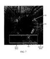
- FIG. 7illustrates registration of another sample patch image within another sample baseline image.
- FIG. 8shows another example scan pattern that includes feature scans and patch scans that can be utilized to acquire a sequence of OCT images.
- FIG. 9shows a schematic illustrating generation of a feature map, identification of features on the feature map, and recording positional information of features consistent with some embodiments of the present invention.
- FIG. 10shows a scan pattern to acquire a sequence of OCT images that includes original feature scans and additional feature scans for generating a registered feature map without utilizing a baseline image and a patch image.
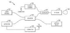
- FIG. 1illustrates an example of an OCT imager 100 that can be utilized in eye examinations according to some embodiments of the present invention.
- OCT imager 100includes light source 101 supplying light to coupler 103 , which directs the light through the sampling arm to XY scan 104 and through the reference arm to optical delay 105 .
- XY scan 104scans the light across eye 109 and collects the reflected light from eye 109 .
- Light reflected from eye 109is captured in XY scan 104 and combined with light reflected from optical delay 105 in coupler 103 to generate an interference signal.
- the interference signalis coupled into detector 102 .
- OCT imager 100can be a time domain OCT imager, in which case depth (or A-scans) are obtained by scanning optical delay 105 , or a Fourier domain imager, in which case detector 102 is a spectrometer that captures the interference signal as a function of wavelength. In either case, the OCT scans are captured by computer 108 . Collections of scans taken along an XY pattern are utilized to generate OCT images.
- An example of an OCT imageris described in U.S. Pat. No. 7,480,058, which is herein incorporated by reference in its entirety.
- a method of Eye Examination utilizing an OCT imageris disclosed in U.S. application Ser. No. 11/656,075, which is herein incorporated by reference in its entirety.
- an apparatus for eye examinationscan include a camera 106 , which can be a fundus camera.
- a camera 106Light from camera 106 is coupled into the sample arm of OCT imager 100 by a coupler 107 .
- Coupler 107prevents light from camera 106 from entering coupler 103 while directing reflected light from eye 109 that originates from camera 106 back into camera 106 .
- Computer 108receives and analyzes both the images from camera 106 and the images from OCT imager 100 . Utilizing the combination of images, accurate and complete OCT images of the nerve head can be obtained.
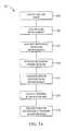
- FIG. 2Aillustrates a procedure for performing eye registration and analysis according to some embodiments of the present invention.
- an automated method and apparatus to perform the eye registration based on two-dimensional (2D) or three-dimensional (3D) OCT imagescan be performed on computer 108 for display on a monitor or other interface device.
- the 2D fundus video imagewhich does not include depth information, is obtained at the output of the fundus camera 106 .
- OCT imageswhich do include depth information, are output from detector 102 and are composed or arranged, depending on their scan patterns, to display as a 2D enface image or a 3D volume data, as desired for a particular evaluation.
- scan datais stored on computer 108 for subsequent analysis.
- a fundus image from fundus camera 106may also be stored on computer 108 .
- the parameters of subsequent image processing techniquesmay be calculated more robustly and efficiently, leading to better accurate diagnosis by physicians.
- Procedure 201 shown in FIG. 2Ais a process for registering and analyzing images that is consistent with some embodiments of the present invention.
- a baseline imageis acquired and saved, if that image has not already been obtained.
- scan pattern imagesare acquired. Scan pattern images may include feature scans and patch scans.
- a patch imageis formed from the patch scans.
- the patch imageis registered against the baseline image.
- a feature mapis generated from the feature scans.
- the features in the feature mapare identified.
- positional information of features from the feature mapare recorded.
- the patch imageis precisely located within the baseline image, regardless of whether the eye has moved or individual blood vessels or other features have changed.
- Featuresare then identified and located precisely with respect to the baseline image in order to monitor changes in feature positions and other attributes.
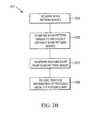
- Procedure 251 shown in FIG. 2Bshows another procedure for registering and analyzing images consistently with the present invention.
- scan pattern imagesare acquired in step 253 .
- the scan pattern imagesinclude original feature scans and additional feature scans.
- the scan pattern imagesare registered with respect to previously obtained scan pattern images.
- a features mapis generated from the scan pattern images.
- position information for features identified in the features mapis recorded. The position and condition of features identified can then be tracked over time in a precise fashion.
- images from other modalitiesmay be taken simultaneously with the OCT images, for example the 2D fundus video image taken by fundus camera 106 in FIG. 1 .
- the 3D OCT images acquired according to some embodiments of the present inventioncan perform well in the presence of eye motion and blood vessel displacement that may occur during the scans.
- some embodiments of the present inventioncan be utilized for more accurate evaluating the eye tissue structure for diagnosing eye diseases.
- An enface imagelike a fundus image, can be composed by summing the tissue reflectivity of a sequence OCT images.
- An algorithm to register and map out the eye tissue structureaccurately then provides for accurate location of features and tracking of changes of those features over time.
- Eye registration methodscan be utilized in the diagnoses of eye pathologies in the fovea, for example Diabetic Retinopathy. These methods can also be utilized in the diagnoses of eye pathologies in the optic nerve head, for example Glaucoma.
- FIG. 3shows an example of baseline scan pattern 300 that can be utilized to acquire a sequence of OCT images.
- Scan pattern 300which in this case includes horizontal scans 303 and vertical scans 305 , can be arranged to substantially cover the eye features of interest, for example, the fovea or optic nerve head.
- the baseline imageis then generated from scan pattern 300 , similar to the generation of an enface image, by summing all or partial tissue reflectivity of the scanned OCT images.
- a baseline image 404 formed in such a fashionis shown in FIG. 4 .
- FIG. 4shows registration of a sample patch image 402 within a sample baseline image 404 .
- Baseline image 404is generated from a baseline scan pattern such as baseline scan pattern 300 .
- Patch image 402is generated from patch scans.
- featuressuch as the retinal blood vessels in baseline image 404 can be enhanced and can be utilized as landmarks to help in registering patch image 402 .
- Other featuresmay also be utilized, such as retinal thicknesses.
- FIG. 5shows a scan pattern 500 that can be utilized to generate a sequence of OCT images.
- Scan pattern 500includes feature scans 502 denoted by solid lines and patch scans 504 denoted by broken lines.
- a feature mapcan be generated from feature scans 502 .
- a patch imagesuch as patch image 402 can be generated from patch scans 504 and used for registration with baseline image 404 in step 209 .
- Retinal thicknessmeasured from the inner limiting membrane (ILM) to the retinal pigment epithelium (RPE), can be used as a feature and is a useful illustration because it is an important consideration in the assessment of many macular diseases.
- Retinal thicknessmay be increased with edema, which can have a profound effect on visual acuity.
- the accumulation of intra-retinal fluidwill lead to both an increased retinal thickness, and also a change in the scattering properties of the retinal tissue, which is detectable in an OCT scan.
- FIG. 6shows a schematic picture illustrating generation of a feature map, which is accomplished in step 211 of FIG. 2A , identifying features in the feature map, and recording the positional information of features as in steps 211 through 215 of procedure 201 .
- a vertical retinal thickness scan 602 and a horizontal thickness scan 604are shown.
- An important location to measure retinal thickeningis directly in the fovea, as indicated with the two thinning areas in thickness scans 602 and 604 .
- the location of that pointis shown as point C of feature map 606 .
- This type of measurementcan be particular useful in tracking patients with macular edema due to diabetic retinopathy, or for screening and following patients with cystoid macular edema following cataract surgery.
- retinal thicknessmay be decreased with atrophy or scattering.
- Retinal thickness map 606is an example of a feature map for illustrative purposes. Other features besides retinal thickness may also be monitored and utilized in the feature map.
- a patch image such as patch image 402can be generated from a patch scan similar to generation of the baseline image as described above.
- a feature map such as feature map 606is generated from feature scans 502 of FIG. 5 using a 2D interpolation technique.
- point Aindicates the aiming center of scan pattern 500
- point Bthe aiming center of baseline scan pattern 300
- point Ca feature location, which in FIG. 6 is the fovea as shown in scans 602 and 604 in feature scan 502 .
- Registrationlocates point B in feature map 606 relative to point A by determining the position of patch image 402 within baseline image 404 .
- the landmarkse.g. blood vessels or other features
- the blood vessels in patch image 402 and/or baseline image 404can become distorted or discontinued.
- Applying a thinning (skeletonization) algorithm followed by an edge-tracing operation to each image, the amount of displacement ( ⁇ x, ⁇ y) at the distorted or discontinued locationscan be obtained and corrected.
- the rectified patch imageis registered in the rectified baseline image.
- Image processing techniquessuch as matching and autocorrelation can be utilized in the fulfillment of a registration to align the landmarks of patch image 402 with the correspondingly identical landmarks of baseline image 406 .
- high-performance computing hardware and techniquessuch as the hardware-related Streaming SIMD (Single Instruction Multiple Data) Extension (SSE), can be used to increase the speed of performing a registration of patch image 402 with baseline image 404 .
- processing of the datamay be accomplished on external computing systems.
- features found in the feature mapare important in the assessment of many macular diseases.
- EDRSEarly Treatment Diabetic Retinopathy Study
- the foveapoint C
- the positional information of the foveacannot often be obtained correctly, especially for patients of severe retinal edema. The positional information may need to be adjusted by experienced clinicians.
- positional informationcan be recorded together with baseline image 404 , as described in the next step, and utilized in subsequent scans. Therefore, in some embodiments of the invention, positional information may be adjusted by a clinician prior to storing the data.
- the fovea(point C) has been identified, its positional information within baseline image 404 can be computed and recorded.
- the relative position between point B and point C in feature map 606is readily obtained.
- the fovea location, point C in feature map 606 , within baseline image 404can be obtained by simple coordinate transformations, taking into account possible differences in the scan resolutions. Consequently, when a patient has another examination with a scan pattern such as scan pattern 500 shown in FIG. 5 , the registration methods can be utilized to compute the new point location B with respect to a probably different point A (aiming center) in feature map 606 . Because the positional information of the fovea has been recorded within baseline image 404 , the fovea location in the newly generated feature map 606 is readily obtained, again, by simple coordinate transformations.
- a baseline imagecan also be used for the examination of the optic nerve head. Once acquired, the baseline image is saved and used for further studies such as a progressive analyses.
- a pattern such as scan pattern 300 shown in FIG. 3may be utilized to acquire a sequence of OCT images, wherein the scan pattern substantially covers the eye features of interest, for examples, the optic disc center.
- other scan patternscan be utilized for both baseline, feature, and patch scans.
- FIG. 7illustrates registration of a patch image 701 within a sample baseline image 703 that includes an optic disc center 705 .
- Baseline image 703is generated from baseline scan pattern 801 as shown in FIG. 8 .
- Patch image 701is formed from patch scan pattern 803 as shown in FIG. 8 .
- FIG. 8shows scan pattern 800 , which can be utilized to acquire a sequence of OCT images, wherein the scan pattern substantially covers a nerve head region 705 .
- Scan pattern 801(designated by solid lines) can be utilized for forming baseline image 703 . Further, scan pattern 801 can be utilized to obtain feature scans.
- Scan pattern 803(designated by dashed lines) are patch scans. As discussed above, feature scans are utilized to generate a feature map whereas patch scans are utilized for generating a patch image to be used for registration against baseline image 703 . As shown in FIG. 8 , scan pattern 801 is a radial scan.
- baseline image 703can be generated similar to an enface image and is composed by summing all or partial tissue reflectivity of the scanned OCT images.
- Features such as retinal blood vesselscan be enhanced and can be utilized as landmarks to help with registration.
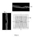
- FIG. 9shows a schematic picture illustrating the steps of generating a feature map, identifying features in the feature map, and recording the positional information of features in the present invention.
- Retinal thicknessmeasured from the ILM to the retinal nerve fiber layer (RNFL), as discussed above, can be used as a feature for registration.
- Retinal thicknesscan be an important feature because thinning in the RNFL thickness may be a powerful indicator of neurodegenerative diseases such as glaucoma.
- An important location to measure retinal thinningis directly related to the optic disc center, which is indicated at point C in feature map 900 shown in FIG. 9 .
- the thinning in the area of radius 1.725 mm from the optic disc centercan have a profound effect on visual acuity.
- the radii of the circle scans 903 shownare 1.25 mm, 1.40 mm, 1.55 mm, 1.70 mm, 1.85 mm, and 2.00 mm, respectively.
- the feature mapis also segregated into areas, including the ST: Superior Temporal, TU: Temporal Upper, TL: Temporal Lower, IT: Inferior Temporal, IN: Inferior Nasal, NL: Nasal Lower, NU: Nasal Upper, and SN: Superior Nasal areas.
- feature map 900may be color coded to show thickness. This type of measurement can be particular useful in tracking patients with glaucoma.
- FIG. 8illustrates a scan pattern 800 to acquire a sequence of OCT images that includes feature scans 801 (solid lines) to generate the feature map for diagnosis, and patch scans 803 (broken lines) for generating a patch image to be used for registration baseline image 703 .
- Baseline image 703may also be acquired from scan 801 .
- Patch image 701can be generated similar to baseline image 703 as described above.
- Feature map 900is generated from feature scans 801 in FIG. 8 , typically utilizing 2D interpolation techniques.
- Point Aindicates the aiming center of the scan pattern 801
- point Bthe aiming center of the baseline scan pattern resulting in baseline image 703
- point Cthe feature location, in this example the optic disc center, in feature map 900 .
- a registration methodlocates point B in FIG. 9 relative to point A.
- the landmarkse.g. blood vessels
- the blood vessels in patch image 701 and/or baseline image 703can become distorted or discontinued.
- Applying a thinning (skeletonization) algorithm followed by an edge-tracing operation to each imagethe amount of displacements ( ⁇ x, ⁇ y) at the distorted or discontinued locations can be obtained and utilized to correct the distortion.
- the rectified patch and rectified baseline imagesare used for the registration.
- Image processing techniquessuch as image alignment and autocorrelation can be utilized to match patch image 701 with baseline image 703 .
- high-performance computing techniquessuch as the hardware-related Streaming SIMD (Single Instruction Multiple Data) Extension (SSE), may be utilized to increase the speed of performance, or the images may be evaluated at a later time on an external system.
- SSESingle Instruction Multiple Data
- features in feature map 900can be important in the assessment of many macular diseases.
- the optic disk center (point C)may be identified by detecting the disc boundaries along the circle-scanned and radial-scanned OCT images resulting from scan 801 .
- the positional information of the optic disc centercannot often be obtained correctly, especially for patients with severe macular diseases.
- the positional informationmay be adjusted by experienced clinicians and those adjustments recorded together with baseline image 703 .
- the optic disc center (point C)After the optic disc center (point C) has been identified, its positional information within baseline image 703 can be computed and recorded. First, the relative position between point B and point C in feature map 900 is readily obtained. Then, the optic disc center location within baseline image 703 can be obtained by simple coordinate transformations, taking into account possible differences in the scan resolutions. Consequently, when a patient has another examination with a scan pattern such as scan pattern 800 of FIG. 8 , the disclosed registration methods compute the new point location B with respect to a probably different point A (aiming center) in feature map 900 . Because the positional information of the optic disc center has been recorded within baseline image 703 , the optic disc center location in the newly generated feature map is readily obtained, again, by simple coordinate transformations.
- a patch imagemay or may not be overlapped with the region corresponding with the feature map.
- no patch image or baseline imageare used. Instead, additional feature scans are used to increase the scanning density such that registration can be reliably performed against images formed from the feature scans. In other words, all the scans can he utilized in generating a feature map.
- FIG. 10shows a scan pattern 1000 to acquire a sequence of OCT images that may be utilized in procedure 251 .
- Scan pattern 1000includes original feature scans 1003 corresponding to solid lines and additional feature scans 1005 corresponding to broken lines.
- Feature scans 1003 and additional feature scans 1005can be utilized to generate a registered feature map such as those shown in FIGS. 9 and 6 without using either a baseline image or a patch image.
- the additional feature scans 1005can be utilized for registration.
- the additional scansare within the region covering the feature map, and thus all the scanned images contribute to generation of the feature map.
- a 2D or 3D intensity imagea simulated scanning laser ophthalmoscope (SSLO) image
- SSLOsimulated scanning laser ophthalmoscope
- feature map 900 based on feature scans 1000can be created.
- a registration method to locate point B relative to point A in feature map 900is similar to that described with FIG. 9 , except that point B now corresponds to the aiming point of a previously obtained feature map.
- the landmarkse.g. blood vessels
- the rectified SSLO imagesare used for the registration.
- Image processing techniquessuch as alignment and autocorrelation, can be utilized to align the two SSLO images.
- High-performance computing techniquessuch as the hardware-related Streaming SIMD (Single Instruction Multiple Data) Extension (SSE), can be used to increase the speed of performance.
- SSESingle Instruction Multiple Data
- a RNFL 3.45 mm profile chartis commonly used for the diagnosis of glaucoma. This chart is centered at the optic disc center. As shown in FIG. 9 , the optic disk center (point C) may be identified by detecting the disc boundaries along the circle-scanned and radial-scanned OCT images. However, the positional information of the optic disc center cannot often be obtained correctly, especially for patients of severe macular diseases. The positional information may need to be adjusted by experienced clinicians and the positional information recorded together with the baseline image, as described in the next step.
- the optic disc center(point C) has been identified, its positional information within the baseline image can be computed and recorded.
- the relative position between point B and point C in feature map 900is readily obtained.
- the optic disc center location within the baseline imagecan be obtained by simple coordinate transformations due to possible differences in the scan resolutions. Consequently, when a patient has another examination with a scan pattern like scan 1000 in FIG. 10 , the disclosed registration methods compute the new point location B with respect to a probably different point A (aiming center) in the feature map. Since the positional information of the optic disc center has been recorded within the baseline image, the optic disc center location in the newly generated feature map is readily obtained, again, by simple coordinate transformations.
- Formation of a baseline image from baseline scans, patch image from patch scans, or feature images from feature scanscan include any number of image enhancement techniques. Such techniques include image enhancement, smoothing, and motion detection and correction. Further, matching one image to another, as is performed when a patch image is registered to a background image or a feature image is registered to previously obtained feature images, may also be undertaken. These image manipulation techniques can be undertaken on computer 108 as shown in FIG. 1 for display to an operator on a display, which is part of computer 108 . Alternatively, data from scanner 100 shown in FIG. 1 may be downloaded to another computer for ultimate data analysis.
- featurescan be identified automatically by analyzing images formed from the scan.
- the fovea as a featuremay be detected by locating the minimum in the thickness map representing the distance between the retinal ILM layer to the IPL layer or the RPE layer.
- the optic disc centercan be identified by locating the optic disc boundary in an image that includes the optic disk and computing the geometric center of the disc boundary.
- the optic disc boundaryfor example, can be determined in an enface image taken along with the OCT scans.
Landscapes
- Health & Medical Sciences (AREA)
- Life Sciences & Earth Sciences (AREA)
- Engineering & Computer Science (AREA)
- Heart & Thoracic Surgery (AREA)
- Molecular Biology (AREA)
- Biophysics (AREA)
- Ophthalmology & Optometry (AREA)
- Biomedical Technology (AREA)
- Signal Processing (AREA)
- Medical Informatics (AREA)
- Physics & Mathematics (AREA)
- Surgery (AREA)
- Animal Behavior & Ethology (AREA)
- General Health & Medical Sciences (AREA)
- Public Health (AREA)
- Veterinary Medicine (AREA)
- Eye Examination Apparatus (AREA)
- Investigating Or Analysing Materials By Optical Means (AREA)
Abstract
Description
Claims (21)
Priority Applications (1)
| Application Number | Priority Date | Filing Date | Title |
|---|---|---|---|
| US12/423,757US8205991B2 (en) | 2008-04-14 | 2009-04-14 | Method of eye registration for optical coherence tomography |
Applications Claiming Priority (2)
| Application Number | Priority Date | Filing Date | Title |
|---|---|---|---|
| US12410908P | 2008-04-14 | 2008-04-14 | |
| US12/423,757US8205991B2 (en) | 2008-04-14 | 2009-04-14 | Method of eye registration for optical coherence tomography |
Publications (2)
| Publication Number | Publication Date |
|---|---|
| US20090257636A1 US20090257636A1 (en) | 2009-10-15 |
| US8205991B2true US8205991B2 (en) | 2012-06-26 |
Family
ID=40887085
Family Applications (1)
| Application Number | Title | Priority Date | Filing Date |
|---|---|---|---|
| US12/423,757Active2030-09-15US8205991B2 (en) | 2008-04-14 | 2009-04-14 | Method of eye registration for optical coherence tomography |
Country Status (6)
| Country | Link |
|---|---|
| US (1) | US8205991B2 (en) |
| EP (1) | EP2306888A1 (en) |
| JP (1) | JP5739323B2 (en) |
| CN (1) | CN102056533B (en) |
| CA (1) | CA2721224A1 (en) |
| WO (1) | WO2009128912A1 (en) |
Cited By (12)
| Publication number | Priority date | Publication date | Assignee | Title |
|---|---|---|---|---|
| US20110222731A1 (en)* | 2008-11-21 | 2011-09-15 | Henry Hacker | Computer Controlled System for Laser Energy Delivery to the Retina |
| US20120083667A1 (en)* | 2010-09-30 | 2012-04-05 | Nidek Co., Ltd. | Method of observing a three-dimensional image of examinee's eye |
| US20130272590A1 (en)* | 2008-10-17 | 2013-10-17 | Canon Kabushiki Kaisha | Image processing apparatus and image processing method for a tomogram of an eye region |
| US10610096B2 (en) | 2016-12-21 | 2020-04-07 | Acucela Inc. | Miniaturized mobile, low cost optical coherence tomography system for home based ophthalmic applications |
| US11357401B2 (en) | 2018-06-20 | 2022-06-14 | Acucela Inc. | Miniaturized mobile, low cost optical coherence tomography system for home based ophthalmic applications |
| US11393094B2 (en) | 2020-09-11 | 2022-07-19 | Acucela Inc. | Artificial intelligence for evaluation of optical coherence tomography images |
| US11497396B2 (en) | 2021-03-24 | 2022-11-15 | Acucela Inc. | Axial length measurement monitor |
| US11684254B2 (en) | 2020-08-04 | 2023-06-27 | Acucela Inc. | Scan pattern and signal processing for optical coherence tomography |
| US11730363B2 (en) | 2019-12-26 | 2023-08-22 | Acucela Inc. | Optical coherence tomography patient alignment system for home based ophthalmic applications |
| US11911105B2 (en) | 2020-09-30 | 2024-02-27 | Acucela Inc. | Myopia prediction, diagnosis, planning, and monitoring device |
| US11941788B2 (en) | 2018-03-20 | 2024-03-26 | Nikon Corporation | Image processing method, program, opthalmic device, and choroidal blood vessel image generation method |
| US11974807B2 (en) | 2020-08-14 | 2024-05-07 | Acucela Inc. | System and method for optical coherence tomography a-scan decurving |
Families Citing this family (28)
| Publication number | Priority date | Publication date | Assignee | Title |
|---|---|---|---|---|
| US11839430B2 (en) | 2008-03-27 | 2023-12-12 | Doheny Eye Institute | Optical coherence tomography-based ophthalmic testing methods, devices and systems |
| US8348429B2 (en) | 2008-03-27 | 2013-01-08 | Doheny Eye Institute | Optical coherence tomography device, method, and system |
| US8718743B2 (en) | 2008-04-24 | 2014-05-06 | Duke University | Methods for single-pass volumetric bidirectional blood flow imaging spectral domain optical coherence tomography using a modified hilbert transform |
| US8079711B2 (en)* | 2008-04-24 | 2011-12-20 | Carl Zeiss Meditec, Inc. | Method for finding the lateral position of the fovea in an SDOCT image volume |
| EP3884844A1 (en) | 2008-07-18 | 2021-09-29 | Doheny Eye Institute | Optical coherence tomography-based ophthalmic testing methods, devices and systems |
| US8693745B2 (en)* | 2009-05-04 | 2014-04-08 | Duke University | Methods and computer program products for quantitative three-dimensional image correction and clinical parameter computation in optical coherence tomography |
| JP5627260B2 (en)* | 2009-05-22 | 2014-11-19 | キヤノン株式会社 | Imaging apparatus and imaging method |
| TWI408338B (en)* | 2009-08-11 | 2013-09-11 | Univ Nat Taiwan | Interference measuring device and measuring method thereof |
| JP5656414B2 (en)* | 2010-01-29 | 2015-01-21 | キヤノン株式会社 | Ophthalmic image capturing apparatus and ophthalmic image capturing method |
| JP5754976B2 (en) | 2010-03-31 | 2015-07-29 | キヤノン株式会社 | Image processing apparatus and control method |
| PL2563206T3 (en)* | 2010-04-29 | 2018-12-31 | Massachusetts Institute Of Technology | Method and apparatus for motion correction and image enhancement for optical coherence tomography |
| US9279659B2 (en) | 2011-01-21 | 2016-03-08 | Duke University | Systems and methods for complex conjugate artifact resolved optical coherence tomography |
| FR2973997B1 (en)* | 2011-04-15 | 2014-08-22 | Univ Paris Curie | DEVICE FOR AIDING THE DETECTION OF ANATOMICAL CHARACTERISTICS OF AT LEAST ONE PORTION OF A FABRIC. METHOD FOR AIDING THE DETECTION OF ANATOMIC CHARACTERISTICS OF AT LEAST ONE PORTION OF A FABRIC |
| JP2014527434A (en)* | 2011-08-09 | 2014-10-16 | オプトビュー,インコーポレーテッド | Feature motion correction and normalization in optical coherence tomography |
| CN102436651B (en)* | 2011-08-25 | 2013-06-19 | 清华大学 | Method and system for extracting three-dimensional hierarchical boundaries of retina OCT (Optical Coherence Tomography) volumetric data |
| CN104039215B (en)* | 2011-12-28 | 2016-10-19 | 视乐有限公司 | Method and apparatus for optical coherence tomography |
| US9357916B2 (en)* | 2012-05-10 | 2016-06-07 | Carl Zeiss Meditec, Inc. | Analysis and visualization of OCT angiography data |
| US8774510B2 (en)* | 2012-09-11 | 2014-07-08 | Sharp Laboratories Of America, Inc. | Template matching with histogram of gradient orientations |
| US9107610B2 (en)* | 2012-11-30 | 2015-08-18 | Kabushiki Kaisha Topcon | Optic neuropathy detection with three-dimensional optical coherence tomography |
| US10772497B2 (en) | 2014-09-12 | 2020-09-15 | Envision Diagnostics, Inc. | Medical interfaces and other medical devices, systems, and methods for performing eye exams |
| US9226856B2 (en) | 2013-03-14 | 2016-01-05 | Envision Diagnostics, Inc. | Inflatable medical interfaces and other medical devices, systems, and methods |
| US9955865B2 (en)* | 2013-04-11 | 2018-05-01 | Novartis Ag | Method and system to detect ophthalmic tissue structure and pathologies |
| EP3349642B1 (en) | 2015-09-17 | 2020-10-21 | Envision Diagnostics, Inc. | Medical interfaces and other medical devices, systems, and methods for performing eye exams |
| JP6598713B2 (en)* | 2016-03-11 | 2019-10-30 | キヤノン株式会社 | Information processing device |
| EP3448234A4 (en) | 2016-04-30 | 2019-05-01 | Envision Diagnostics, Inc. | MEDICAL DEVICES, SYSTEMS AND METHODS FOR OPERATING OCULAR EXAMINATIONS AND OCULOMETRY |
| US10010249B1 (en)* | 2017-03-23 | 2018-07-03 | Doheny Eye Institute | Systems, methods, and devices for optical coherence tomography multiple enface angiography averaging |
| WO2019108934A1 (en)* | 2017-11-30 | 2019-06-06 | Duke University | Systems and methods for providing surface contrast to display images for micro-surgical applications |
| JP2023086533A (en)* | 2021-12-10 | 2023-06-22 | 国立大学法人 筑波大学 | Information processing device, information processing method, and computer program |
Citations (16)
| Publication number | Priority date | Publication date | Assignee | Title |
|---|---|---|---|---|
| WO2001078584A2 (en) | 2000-04-19 | 2001-10-25 | Alcon Universal Ltd. | Eye registration and astigmatism alignment control systems and method |
| US20040042022A1 (en)* | 2002-09-03 | 2004-03-04 | Innolutions, Inc. | Active color control for a printing press |
| US20040263785A1 (en) | 2003-06-16 | 2004-12-30 | Visx, Inc. | Methods and devices for registering optical measurement datasets of an optical system |
| US20060115110A1 (en)* | 2004-11-09 | 2006-06-01 | Rodriguez Tony F | Authenticating identification and security documents |
| WO2006078802A1 (en) | 2005-01-21 | 2006-07-27 | Massachusetts Institute Of Technology | Methods and apparatus for optical coherence tomography scanning |
| US20070115481A1 (en) | 2005-11-18 | 2007-05-24 | Duke University | Method and system of coregistrating optical coherence tomography (OCT) with other clinical tests |
| WO2007084748A2 (en) | 2006-01-19 | 2007-07-26 | Optovue, Inc. | A method of eye examination by optical coherence tomography |
| US20080267515A1 (en)* | 2004-09-28 | 2008-10-30 | Xerox Corporation | Encoding invisible electronic information in a printed document |
| US20080310757A1 (en)* | 2007-06-15 | 2008-12-18 | George Wolberg | System and related methods for automatically aligning 2D images of a scene to a 3D model of the scene |
| US7480058B2 (en) | 2006-01-19 | 2009-01-20 | Optovue, Inc. | Fourier-domain optical coherence tomography imager |
| US20090268161A1 (en)* | 2008-04-24 | 2009-10-29 | Bioptigen, Inc. | Optical coherence tomography (oct) imaging systems having adaptable lens systems and related methods and computer program products |
| US20100030578A1 (en)* | 2008-03-21 | 2010-02-04 | Siddique M A Sami | System and method for collaborative shopping, business and entertainment |
| US20100245838A1 (en)* | 2005-01-21 | 2010-09-30 | Carl Zeiss Meditec, Inc. | Method of motion correction in optical coherence tomography imaging |
| US7924429B2 (en)* | 2004-12-02 | 2011-04-12 | University Of Miami | Enhanced optical coherence tomography for anatomical mapping |
| US20110085136A1 (en)* | 2006-05-01 | 2011-04-14 | Ferguson R Daniel | Hybrid Spectral Domain Optical Coherence Tomography Line Scanning Laser Ophthalmoscope |
| US20110194072A1 (en)* | 2006-10-18 | 2011-08-11 | Olivier Scot S | Compact adaptive optic-optical coherence tomography system |
Family Cites Families (5)
| Publication number | Priority date | Publication date | Assignee | Title |
|---|---|---|---|---|
| JP3639030B2 (en)* | 1995-02-28 | 2005-04-13 | 株式会社東芝 | Image display system and image display method using the system |
| US7480068B2 (en)* | 2001-01-11 | 2009-01-20 | Sharp Laboratories Of America, Inc. | Methods and systems for page-independent spool file sheet assembly |
| US7668342B2 (en)* | 2005-09-09 | 2010-02-23 | Carl Zeiss Meditec, Inc. | Method of bioimage data processing for revealing more meaningful anatomic features of diseased tissues |
| JP5079240B2 (en)* | 2006-02-06 | 2012-11-21 | 株式会社ニデック | Retinal function measuring device |
| JP4869756B2 (en)* | 2006-03-24 | 2012-02-08 | 株式会社トプコン | Fundus observation device |
- 2009
- 2009-04-14EPEP09732715Apatent/EP2306888A1/ennot_activeWithdrawn
- 2009-04-14WOPCT/US2009/002343patent/WO2009128912A1/enactiveApplication Filing
- 2009-04-14CNCN2009801218449Apatent/CN102056533B/ennot_activeExpired - Fee Related
- 2009-04-14CACA2721224Apatent/CA2721224A1/ennot_activeAbandoned
- 2009-04-14USUS12/423,757patent/US8205991B2/enactiveActive
- 2009-04-14JPJP2011505018Apatent/JP5739323B2/ennot_activeExpired - Fee Related
Patent Citations (20)
| Publication number | Priority date | Publication date | Assignee | Title |
|---|---|---|---|---|
| WO2001078584A2 (en) | 2000-04-19 | 2001-10-25 | Alcon Universal Ltd. | Eye registration and astigmatism alignment control systems and method |
| US20040042022A1 (en)* | 2002-09-03 | 2004-03-04 | Innolutions, Inc. | Active color control for a printing press |
| US20040263785A1 (en) | 2003-06-16 | 2004-12-30 | Visx, Inc. | Methods and devices for registering optical measurement datasets of an optical system |
| US20080267515A1 (en)* | 2004-09-28 | 2008-10-30 | Xerox Corporation | Encoding invisible electronic information in a printed document |
| US20060115110A1 (en)* | 2004-11-09 | 2006-06-01 | Rodriguez Tony F | Authenticating identification and security documents |
| US7924429B2 (en)* | 2004-12-02 | 2011-04-12 | University Of Miami | Enhanced optical coherence tomography for anatomical mapping |
| US20100245838A1 (en)* | 2005-01-21 | 2010-09-30 | Carl Zeiss Meditec, Inc. | Method of motion correction in optical coherence tomography imaging |
| US20060187462A1 (en)* | 2005-01-21 | 2006-08-24 | Vivek Srinivasan | Methods and apparatus for optical coherence tomography scanning |
| US20110134394A1 (en)* | 2005-01-21 | 2011-06-09 | Massachusetts Institute Of Technology | Methods and apparatus for optical coherence tomography scanning |
| WO2006078802A1 (en) | 2005-01-21 | 2006-07-27 | Massachusetts Institute Of Technology | Methods and apparatus for optical coherence tomography scanning |
| US20070115481A1 (en) | 2005-11-18 | 2007-05-24 | Duke University | Method and system of coregistrating optical coherence tomography (OCT) with other clinical tests |
| US7593559B2 (en)* | 2005-11-18 | 2009-09-22 | Duke University | Method and system of coregistrating optical coherence tomography (OCT) with other clinical tests |
| US7480058B2 (en) | 2006-01-19 | 2009-01-20 | Optovue, Inc. | Fourier-domain optical coherence tomography imager |
| US7744221B2 (en) | 2006-01-19 | 2010-06-29 | Optovue, Inc. | Method of eye examination by optical coherence tomography |
| WO2007084748A2 (en) | 2006-01-19 | 2007-07-26 | Optovue, Inc. | A method of eye examination by optical coherence tomography |
| US20110085136A1 (en)* | 2006-05-01 | 2011-04-14 | Ferguson R Daniel | Hybrid Spectral Domain Optical Coherence Tomography Line Scanning Laser Ophthalmoscope |
| US20110194072A1 (en)* | 2006-10-18 | 2011-08-11 | Olivier Scot S | Compact adaptive optic-optical coherence tomography system |
| US20080310757A1 (en)* | 2007-06-15 | 2008-12-18 | George Wolberg | System and related methods for automatically aligning 2D images of a scene to a 3D model of the scene |
| US20100030578A1 (en)* | 2008-03-21 | 2010-02-04 | Siddique M A Sami | System and method for collaborative shopping, business and entertainment |
| US20090268161A1 (en)* | 2008-04-24 | 2009-10-29 | Bioptigen, Inc. | Optical coherence tomography (oct) imaging systems having adaptable lens systems and related methods and computer program products |
Non-Patent Citations (2)
| Title |
|---|
| PCT International Preliminary Report on Patentability dated Oct. 28, 2010, in related International Appl. No. PCT/US2009/002343. |
| PCT International Search Report and the Written Opinion mailed Aug. 31, 2009, in related International Application No. PCT/US2009/002343. |
Cited By (28)
| Publication number | Priority date | Publication date | Assignee | Title |
|---|---|---|---|---|
| US20130272590A1 (en)* | 2008-10-17 | 2013-10-17 | Canon Kabushiki Kaisha | Image processing apparatus and image processing method for a tomogram of an eye region |
| US9053536B2 (en)* | 2008-10-17 | 2015-06-09 | Canon Kabushiki Kaisha | Image processing apparatus and image processing method for a tomogram of an eye region |
| US20110222731A1 (en)* | 2008-11-21 | 2011-09-15 | Henry Hacker | Computer Controlled System for Laser Energy Delivery to the Retina |
| US8433117B2 (en)* | 2008-11-21 | 2013-04-30 | The United States Of America As Represented By The Secretary Of The Army | Computer controlled system for laser energy delivery to the retina |
| US20120083667A1 (en)* | 2010-09-30 | 2012-04-05 | Nidek Co., Ltd. | Method of observing a three-dimensional image of examinee's eye |
| US9125593B2 (en)* | 2010-09-30 | 2015-09-08 | Nidek Co., Ltd. | Method of observing a three-dimensional image of examinee's eye |
| US9681803B2 (en) | 2010-09-30 | 2017-06-20 | Nidek Co., Ltd. | Method of observing a three-dimensional image of examinee's eye |
| US11627874B2 (en) | 2016-12-21 | 2023-04-18 | Acucela Inc. | Miniaturized mobile, low cost optical coherence tomography system for home based ophthalmic applications |
| US10610096B2 (en) | 2016-12-21 | 2020-04-07 | Acucela Inc. | Miniaturized mobile, low cost optical coherence tomography system for home based ophthalmic applications |
| US11890053B2 (en) | 2016-12-21 | 2024-02-06 | Acucela Inc. | Miniaturized mobile, low cost optical coherence tomography system for home based ophthalmic applications |
| US10952607B2 (en) | 2016-12-21 | 2021-03-23 | Acucela Inc. | Miniaturized mobile, low cost optical coherence tomography system for home based ophthalmic applications |
| US12396639B2 (en) | 2016-12-21 | 2025-08-26 | Acucela Inc. | Miniaturized mobile, low cost optical coherence tomography system for home based ophthalmic applications |
| US12423784B2 (en) | 2018-03-20 | 2025-09-23 | Nikon Corporation | Image processing method, program, ophthalmic device, and choroidal blood vessel image generation method |
| US11941788B2 (en) | 2018-03-20 | 2024-03-26 | Nikon Corporation | Image processing method, program, opthalmic device, and choroidal blood vessel image generation method |
| US11576572B2 (en) | 2018-06-20 | 2023-02-14 | Acucela Inc. | Miniaturized mobile, low cost optical coherence tomography system for home based ophthalmic applications |
| US12290317B2 (en) | 2018-06-20 | 2025-05-06 | Acucela Inc. | Miniaturized mobile, low cost optical coherence tomography system for home based ophthalmic applications |
| US11357401B2 (en) | 2018-06-20 | 2022-06-14 | Acucela Inc. | Miniaturized mobile, low cost optical coherence tomography system for home based ophthalmic applications |
| US11896308B2 (en) | 2018-06-20 | 2024-02-13 | Acucela Inc. | Miniaturized mobile, low cost optical coherence tomography system for home based ophthalmic applications |
| US11730363B2 (en) | 2019-12-26 | 2023-08-22 | Acucela Inc. | Optical coherence tomography patient alignment system for home based ophthalmic applications |
| US11684254B2 (en) | 2020-08-04 | 2023-06-27 | Acucela Inc. | Scan pattern and signal processing for optical coherence tomography |
| US12232810B2 (en) | 2020-08-04 | 2025-02-25 | Acucela Inc. | Scan pattern and signal processing for optical coherence tomography |
| US11974807B2 (en) | 2020-08-14 | 2024-05-07 | Acucela Inc. | System and method for optical coherence tomography a-scan decurving |
| US11620749B2 (en) | 2020-09-11 | 2023-04-04 | Acucela Inc. | Artificial intelligence for evaluation of optical coherence tomography images |
| US11798164B2 (en) | 2020-09-11 | 2023-10-24 | Acucela Inc. | Artificial intelligence for evaluation of optical coherence tomography images |
| US11393094B2 (en) | 2020-09-11 | 2022-07-19 | Acucela Inc. | Artificial intelligence for evaluation of optical coherence tomography images |
| US11911105B2 (en) | 2020-09-30 | 2024-02-27 | Acucela Inc. | Myopia prediction, diagnosis, planning, and monitoring device |
| US11779206B2 (en) | 2021-03-24 | 2023-10-10 | Acucela Inc. | Axial length measurement monitor |
| US11497396B2 (en) | 2021-03-24 | 2022-11-15 | Acucela Inc. | Axial length measurement monitor |
Also Published As
| Publication number | Publication date |
|---|---|
| CN102056533B (en) | 2013-06-12 |
| CA2721224A1 (en) | 2009-10-22 |
| WO2009128912A1 (en) | 2009-10-22 |
| US20090257636A1 (en) | 2009-10-15 |
| JP2011516235A (en) | 2011-05-26 |
| EP2306888A1 (en) | 2011-04-13 |
| JP5739323B2 (en) | 2015-06-24 |
| CN102056533A (en) | 2011-05-11 |
Similar Documents
| Publication | Publication Date | Title |
|---|---|---|
| US8205991B2 (en) | Method of eye registration for optical coherence tomography | |
| JP7579372B2 (en) | Medical image processing device, medical image processing system, medical image processing method and program | |
| EP1976424B1 (en) | A method of eye examination by optical coherence tomography | |
| US8770753B2 (en) | Scanning and processing using optical coherence tomography | |
| JP5698465B2 (en) | Ophthalmic apparatus, display control method, and program | |
| EP2742856B1 (en) | Optic neuropathy detection with three-dimensional optical coherence tomography | |
| US20110137157A1 (en) | Image processing apparatus and image processing method | |
| JP2020058800A (en) | Image processing apparatus, image processing method and program | |
| US9615734B2 (en) | Ophthalmologic apparatus | |
| US20130039557A1 (en) | Motion correction and normalization of features in optical coherence tomography | |
| JP2013215243A (en) | Image processing apparatus, image forming method, and program | |
| US20150116660A1 (en) | Fundus observation apparatus and fundus image analyzing apparatus | |
| WO2020138128A1 (en) | Image processing device, image processing method, and program | |
| JP2016049183A (en) | Ophthalmologic apparatus and control method thereof |
Legal Events
| Date | Code | Title | Description |
|---|---|---|---|
| AS | Assignment | Owner name:OPTOVUE, INC., CALIFORNIA Free format text:ASSIGNMENT OF ASSIGNORS INTEREST;ASSIGNORS:WEI, JAY;JANG, BEN KWEI;LUH, SHUW-SHENN;AND OTHERS;REEL/FRAME:022889/0529 Effective date:20090629 | |
| STCF | Information on status: patent grant | Free format text:PATENTED CASE | |
| AS | Assignment | Owner name:SILICON VALLEY BANK, CALIFORNIA Free format text:SECURITY AGREEMENT;ASSIGNOR:OPTOVUE, INC.;REEL/FRAME:029117/0574 Effective date:20120829 | |
| AS | Assignment | Owner name:OPTOVUE, INC., CALIFORNIA Free format text:RELEASE OF SECURITY INTEREST;ASSIGNOR:SILICON VALLEY BANK;REEL/FRAME:033063/0641 Effective date:20140530 | |
| FPAY | Fee payment | Year of fee payment:4 | |
| MAFP | Maintenance fee payment | Free format text:PAYMENT OF MAINTENANCE FEE, 8TH YR, SMALL ENTITY (ORIGINAL EVENT CODE: M2552); ENTITY STATUS OF PATENT OWNER: SMALL ENTITY Year of fee payment:8 | |
| AS | Assignment | Owner name:SOCIETE GENERALE, AS SECURITY AGENT, FRANCE Free format text:NOTICE OF SECURITY INTEREST - PATENTS;ASSIGNOR:OPTOVUE, INC.;REEL/FRAME:058603/0315 Effective date:20211231 | |
| MAFP | Maintenance fee payment | Free format text:PAYMENT OF MAINTENANCE FEE, 12TH YR, SMALL ENTITY (ORIGINAL EVENT CODE: M2553); ENTITY STATUS OF PATENT OWNER: SMALL ENTITY Year of fee payment:12 | |
| AS | Assignment | Owner name:SOCIETE GENERALE, AS SECURITY AGENT, FRANCE Free format text:RELEASE BY SECURED PARTY;ASSIGNOR:OPTOVUE, INC.;REEL/FRAME:064420/0570 Effective date:20230727 |