US8205916B2 - High-pressure threaded union with metal-to-metal seal, and metal ring gasket for same - Google Patents
High-pressure threaded union with metal-to-metal seal, and metal ring gasket for sameDownload PDFInfo
- Publication number
- US8205916B2 US8205916B2US13/079,379US201113079379AUS8205916B2US 8205916 B2US8205916 B2US 8205916B2US 201113079379 AUS201113079379 AUS 201113079379AUS 8205916 B2US8205916 B2US 8205916B2
- Authority
- US
- United States
- Prior art keywords
- metal ring
- ring gasket
- annular
- fluid conduit
- nut
- Prior art date
- Legal status (The legal status is an assumption and is not a legal conclusion. Google has not performed a legal analysis and makes no representation as to the accuracy of the status listed.)
- Expired - Lifetime
Links
Images


Classifications
- F—MECHANICAL ENGINEERING; LIGHTING; HEATING; WEAPONS; BLASTING
- F16—ENGINEERING ELEMENTS AND UNITS; GENERAL MEASURES FOR PRODUCING AND MAINTAINING EFFECTIVE FUNCTIONING OF MACHINES OR INSTALLATIONS; THERMAL INSULATION IN GENERAL
- F16L—PIPES; JOINTS OR FITTINGS FOR PIPES; SUPPORTS FOR PIPES, CABLES OR PROTECTIVE TUBING; MEANS FOR THERMAL INSULATION IN GENERAL
- F16L17/00—Joints with packing adapted to sealing by fluid pressure
- F16L17/06—Joints with packing adapted to sealing by fluid pressure with sealing rings arranged between the end surfaces of the pipes or flanges or arranged in recesses in the pipe ends or flanges
- F16L17/08—Metal sealing rings
Definitions
- the present inventionrelates generally to sealed joints for high-pressure fluid conduits and, in particular, to a metal ring gasket for threaded unions for use in very high fluid pressure applications.
- Threaded unionsare used to provide fluid-tight joints in fluid conduits. Threaded unions are held together by a threaded nut that is tightened to a required torque using a hammer or a wrench. In the oil industry, threaded unions are generally constructed using “wing nuts” and are commonly called “hammer unions” or “hammer lug unions”. Hammer unions are designed and manufactured in accordance with the specifications stipulated by the American Petroleum Institute in API 6A entitled “Specification for Wellhead and Christmas Tree Equipment”. Hammer unions are usually available in a variety of sizes (1′′ to 12′′) and a variety of pressure ratings (1000 psi to over 20,000 psi).
- flanged unionsare commonly used in well trees, pipelines and other high-pressure applications where temperature tolerant seals are required, flanged unions are relatively expensive to construct and time-consuming to assemble in the field.
- Metal ring gasketsare known for flanged unions, such as the BX ring gasket manufactured in accordance with API 6A. In operation, however, these BX ring gaskets are deformed beyond their yield strength and must be discarded after a single load cycle.
- Threaded unionsprovide a good alternative to flanged unions from a cost standpoint because they are faster to assemble and less expensive to construct.
- safety concernsrelated to the lack of a reliable high-pressure metal-to-metal seal, use of threaded unions for well tree components and other high-pressure temperature tolerant applications has not been endorsed.
- the inventiontherefore provides a threaded union including a nut that draws together respective mating ends of a first subcomponent and a second subcomponent of the threaded union; the mating end of the first subcomponent comprising a first annular groove that mates with a complementary second annular groove in the mating end of the second subcomponent, the complementary first and second annular grooves respectively having a sloped annular outer face that extends to a respective planar bottom surface of the respective annular grooves; and a metal ring gasket received in the respective annular grooves, the metal ring gasket having a planar top face, a planar bottom face that is parallel to the planar top face, a cylindrical outer face that is perpendicular to the top and bottom faces, and an annular sloped surface between each of the planar top face, the planar bottom face and the cylindrical outer face, the metal ring gasket being elastically deformed, without any plastic deformation, by contact between only the respective sloped annular outer faces of the respective annular grooves and the respective
- the inventionfurther provides a high-pressure fluid conduit including a first fluid conduit subcomponent having a pin end with an annular groove in the pin end, a second fluid conduit subcomponent having a socket end that receives the pin end and has a complementary second annular groove in a bottom of the socket, the first and second annular grooves having respective annular outer faces that slope inwardly to a planar annular bottom surface of the respective annular grooves; and a metal ring gasket compressed between the respective ends of the first and the second fluid conduit subcomponents, the metal ring gasket deforming elastically, without plastic deformation, to provide an energized high-pressure fluid seal when the first and second fluid conduit subcomponents are drawn together by a nut, the metal ring gasket having a planar top face, a planar bottom face that is parallel to the planar top face, a cylindrical outer face, and an annular sloped surface between each of the planar top and bottom faces and the cylindrical outer face, the metal ring gasket being compressed by contact with only the respective first
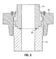
- FIG. 1is a cross-sectional view of a threaded union and a metal ring gasket in accordance with one embodiment of the invention
- FIG. 2is an exploded, cross-sectional view of the threaded union shown in FIG. 1 ;
- FIG. 3is a cross-sectional view of a threaded union and a metal ring gasket in accordance with another embodiment of the invention.
- FIG. 4is a cross-sectional view of the metal ring gasket shown in FIGS. 1-3 immediately prior to elastic deformation of the metal ring gasket as the threaded union is tightened to a sealed condition;
- FIG. 5is a cross-sectional view of the metal ring gasket shown in FIGS. 1-3 schematically illustrating an extent of elastic deformation of the metal ring gasket when the threaded union is in the sealed condition;
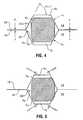
- FIG. 6is a cross-sectional view of the metal ring gasket shown in FIGS. 1 and 3 when the threaded union is in the sealed condition and under elevated fluid pressure;
- FIG. 7is a cross-sectional view of another embodiment of a metal ring gasket in accordance with the invention in a sealed condition under elevated fluid pressures.
- the inventionprovides a threaded union with a metal ring gasket that provides a high-pressure, temperature tolerant, metal-to-metal fluid seal between a first subcomponent and a second subcomponent of the threaded union.
- the metal ring gasketis made of ductile carbon steel for non-corrosive fluid service or ductile stainless steel for corrosive fluid service.
- the metal ring gaskethas outer beveled corners and is received in a beveled annular groove in a mating end of the first subcomponent. When compressed between the first and the second subcomponents, the metal ring gasket deforms elastically to provide an energized high-pressure fluid seal.
- the high-pressure sealis capable of containing fluid pressures of up to at least 30,000 pounds per square inch (psi), and is not affected by elevated temperatures below a melting point of the ductile steel of the metal ring gasket.
- first subcomponent and second subcomponentare meant to denote any two contiguous components of a joint in a fluid conduit that are joined together using a threaded nut.
- FIG. 1illustrates a threaded union 10 in accordance with an embodiment of the invention.
- the threaded union 10includes a first subcomponent 12 and a second subcomponent 14 .
- the first and second subcomponents 12 , 14are generally annular bodies that are interconnected to define a central fluid passageway 15 as part of a high-pressure fluid conduit.
- the first subcomponent 12has a mating end 16 that abuts a mating end 18 of the second subcomponent 14 .
- the first subcomponent 12has a top surface that includes an upwardly facing annular groove 20 .
- the upwardly facing annular groove 20is dimensioned to receive a metal ring gasket 30 in accordance with the invention.
- the second subcomponent 14has a bottom surface that includes a downwardly facing annular groove 22 .
- the upwardly facing and downwardly facing annular grooves 20 , 22mate when the second subcomponent 14 is connected to the first subcomponent 12 to define a hexagonal annular cavity 24 .
- the annular cavity 24need not necessarily be hexagonal to provide the energized high-pressure fluid seal in accordance with the invention.
- the second subcomponent 14is secured to the first subcomponent 12 by a threaded nut 40 .
- the threaded nut 40has box threads 42 for engaging pin threads 44 formed externally on the first subcomponent 12 .
- the threaded nut 40is a wing nut and includes a plurality of lugs 46 that extend radially from a main body 48 of the threaded nut 40 .
- the lugs 46have impact surfaces 46 a which may be impact-torqued using a hammer or mallet (not shown) in the usual way in which a hammer union is “hammered up”.
- the threaded nut 40is a “spanner nut” that includes flats, bores, or the like, that are gripped by a spanner wrench (not shown) to permit the threaded nut 40 to be tightened to a required torque.
- a spanner wrench(not shown) to permit the threaded nut 40 to be tightened to a required torque.
- the wrench used to tighten the nutmay be a torque wrench, which indicates the torque applied to the threaded nut 40 to ensure that it is tightened with a precise amount of torque.
- the threaded nut 40 in accordance with this embodiment of this inventionis constructed in three parts so that a main body of the nut 40 can be a single piece construction for greater strength.
- the nuts for hammer unionsare commonly cut into two parts that are welded together in situ after the nut is positioned above an annular shoulder 14 a of the second subcomponent 14 .
- the threaded nut 40 in accordance with the inventionhas an upper annular shoulder 47 that extends radially inwardly from a top of the main body 48 of the nut 40 .
- the annular shoulder 47abuts a flange 52 that extends radially outwardly from an adapter collar 50 .
- the adapter collar 50is a generally annular multi-piece body having an inner diameter dimensioned to slide over an outer surface of the second subcomponent 14 until a bottom surface 54 of the adapter collar 50 abuts the annular shoulder 14 a of the second subcomponent 14 .
- a bottom surface of the annular shoulder 14 aabuts a top surface 16 of the first subcomponent 12 .
- the multi-piece adapter collar 50is constructed of two symmetrical parts.
- the adapter collar 50includes an annular groove 56 dimensioned to receive an inner edge of a segmented retainer plate 60 .
- the segmented retainer plate 60is secured to a top of the nut 40 by threaded fasteners 62 , which are received in a plurality of tapped bores 49 distributed in a circular pattern around a top of the nut.
- the segmented retainer plate 60is constructed of three wedge-shaped pieces.
- the metal ring gasket 30provides a high-pressure metal-to-metal seal between the first and second subcomponents 12 , 14 .
- the threaded union 10also includes a pair of elastomeric backup seals, e.g. O-rings, which are seated in annular grooves 70 in the second subcomponent. Alternatively, the annular grooves 70 could be machined into the first subcomponent. It will be appreciated that the number of elastomeric annular sealing elements can be varied from zero to three or more.
- FIG. 2illustrates, in an exploded view, the threaded union 10 shown in FIG. 1 .
- the threaded union 10includes a pair of O-rings 80 , each having its own backing member 82 .
- the O-rings 80 and backing members 82are dimensioned to be received in each of the two annular grooves 70 in order to provide the elastomeric backup seal to the metal-to-metal seal provided by the metal ring gasket 30 .
- the first subcomponent 12includes a socket 64 and the upwardly facing annular groove 20 is located in the bottom of the socket 64 .
- the second subcomponent 14includes a pin end 66 and the downwardly facing annular groove 22 is located on a bottom of the pin end 66 .
- the socket 64receives the pin end 66 .
- FIG. 3illustrates a threaded union 10 in accordance with another embodiment of the invention.
- the high-pressure fluid-tight seal between the first and second subcomponents 12 , 14is provided only by the metal ring gasket 30 . Otherwise, the embodiments shown in FIGS. 2 and 3 are identical.
- the metal ring gasket 30has maintained a fluid-tight seal up to a fluid pressure of 30,000 psi.
- the metal ring gasketis also able to maintain a high-pressure seal even if exposed to elevated temperatures due to fire.
- metal ring gasket 30has beveled corners (or beveled surfaces) and an octagonal cross-section.
- the corners of the metal ring gasketare beveled at an angle of 23° ⁇ 1°.
- the metal ring gasket 30is preferably made of steel. Plain carbon steel or stainless steel is selected depending on whether a fluid to be contained is corrosive or non-corrosive.
- AISI 1018nickel-plated cold-drawn steel
- the AISI 1018 steelhas a carbon content of 0.18% (although it may vary from 0.14% to 0.20%), a manganese content of 0.6% to 0.9%, a maximum phosphorus content of 0.04% and a maximum sulfur content of 0.05%.
- the AISI 1018 steelexhibits high machinability (its average machinability rating is 70%), good fracture toughness, good surface hardness (126 HB), high tensile strength (440 MPa), high yield strength (370 MPa), superior ductility (40-50% reduction in cross-sectional area at the fracture load) and is relatively inexpensive.
- other plain carbon steelsmay be substituted, provided they have approximately similar mechanical properties.
- the metal ring gasketmay be made using either AISI 316 stainless steel or AISI 304 stainless steel. Not only are these stainless steels corrosion-resistant but they also possess desirable mechanical properties (in terms of machinability, fracture toughness, surface hardness, tensile strength and yield strength).
- the metal ring gaskets in accordance with the inventionmay be made using metals other than steel (such as aluminum or copper alloys like brass or bronze, for example), which are more temperature-resistant than elastomeric gaskets.
- FIG. 4shows the undeformed metal ring gasket 30 in substantially unloaded contact with the inner beveled surfaces of the annular cavity 24 , for example immediately prior to or immediately after torquing of the threaded nut 40 .
- the annular cavity 24has a hexagonal cross section with internal beveled surfaces, or facets, that have angles that correspond to the bevel angles of the octagonal cross section of the metal ring gasket 30 .
- the top, bottom and inner side surfaces of the metal ring gasketdo not contact the top, bottom or inner surfaces of the annular cavity 24 .
- the metal ring gasketis over-sized to have an outer diameter such that the outer beveled corners must be displaced by elastic deformation causing annular compression of the metal ring gasket 30 by about 0.003′′ when the first subcomponent 12 and the second subcomponent 14 are securely interconnected.
- the oversizing of the metal ring gasketis shown at an exaggerated scale for the purposes of illustration. The 0.003′′ oversizing is considered optimal for the steels described above because the metal ring gasket 30 is elastically, and not plastically deformed in the annular cavity 24 .
- an inner diameter of the metal ring gasket 30is larger than a diameter of the annular cavity 24 .
- the inner diameter of the metal seal ringis such that the gap G B is at least 0.001′′ after the metal ring gasket 30 is elastically deformed in the annular groove 24 .
- the inner diameter of the metal ring gasket 30is about 0.014′′ larger than an inner diameter of the annular cavity 24 before the metal ring gasket is elastically deformed.
- this difference in the diametersis not critical and can be varied considerably, so long as the metal ring gasket 30 can be elastically deformed without the elastic deformation being inhibited by contact with an inner face of the annular cavity 24 . Consequently, if an inner diameter of the metal ring gasket is at least 0.003′′ larger than an inner diameter of the annular cavity 24 , the metal ring gasket can be elastically deformed as required.
- the threaded union 10is torqued or “hammered up” by tightening the nut 40 until the end surfaces 16 , 18 of the first and second subcomponents 12 , 14 abut. Due to the slight over-sizing (about 0.003′′) of the metal ring gasket 30 , the threaded union cannot be overtorqued, and there is no danger of plastic deformation of the metal ring gasket 30 .
- the metal ring gasket 30can therefore be repeatedly reused so long as the sealing surfaces on its beveled faces are not scratched or marred.
- FIG. 6schematically illustrates the threaded union 10 when it is exposed to elevated fluid pressures.
- high fluid pressures in the fluid passage 15force the end surfaces 16 , 18 of the first and second subcomponents 12 , 14 apart due to elastic deformation of the threaded nut 40 .
- Fluid pressureflows through the gap 90 on the inner side of the metal ring gasket 30 .
- the fluid pressureinduces hoop stress in the metal ring gasket 30 that forces the sealing surfaces 30 a , 30 b of the metal ring gasket 30 into tighter contact with the corresponding surfaces of the annular cavity 24 , and the seal is “energized”. Consequently, the higher the fluid pressure (within the pressure capacity of the first and second subcomponents 12 , 14 ) in the central fluid passage 15 , the more energized and tighter the fluid seal.
- FIG. 7schematically illustrates another embodiment of a metal ring gasket 32 in accordance with the invention.
- the metal ring gasket 32has an outer diameter and outer beveled corners that are configured the same as described above with reference to FIGS. 4-6 and the metal ring gasket is elastically deformed in the annular cavity 24 in the same way.
- the metal ring gasket 32is hexagonal in cross-section and has a flat inner side that is spaced from an inner surface of the annular cavity 24 .
- the fluid pressureacts on the flat side to energize the seal as described above.
- the shape of the inner side, and consequently, the cross-sectional shape of the metal ring gaskets 30 , 32is a matter of design choice.
- the threaded union 10 in accordance with the inventionmay be used to construct a high-pressure, fluid-tight seal between a drilling flange, described in applicant's co-pending U.S. patent application Ser. No. 10/656,693 filed Sept. 4, 2003 and a wellhead on a wellhead assembly, as described and illustrated in applicant's co-pending U.S. patent application Ser. No. 10/690,142 (Dallas) entitled METAL RING GASKET FOR A THREADED UNION, which are hereby incorporated by reference, as well as a fluid conduit for any other application.
- the metal ring gasket in accordance with the inventionhas been extensively pressure-tested in a number of threaded unions integrated into different wellhead and well stimulation tool components. It has proven to be extremely reliable and provides a very high-pressure energized seal that is easy to “torque up” using a hammer or a wrench. This permits such components to be more economically constructed and more quickly assembled. Cost savings are therefore realized, while worker safety and environmental protection are ensured.
- the metal ring gasket 30 , 32 for the threaded union 10can be used in a variety of applications to reduce cost, while ensuring high performance and safety in fluid conduits of all types, including wellhead assemblies and well stimulation equipment, where very high pressure and very high temperature resistance are especially important.
Landscapes
- Engineering & Computer Science (AREA)
- General Engineering & Computer Science (AREA)
- Physics & Mathematics (AREA)
- Fluid Mechanics (AREA)
- Mechanical Engineering (AREA)
- Gasket Seals (AREA)
- Joints With Pressure Members (AREA)
Abstract
Description
Claims (20)
Priority Applications (1)
| Application Number | Priority Date | Filing Date | Title |
|---|---|---|---|
| US13/079,379US8205916B2 (en) | 2005-07-14 | 2011-04-04 | High-pressure threaded union with metal-to-metal seal, and metal ring gasket for same |
Applications Claiming Priority (4)
| Application Number | Priority Date | Filing Date | Title |
|---|---|---|---|
| US11/182,588US7484776B2 (en) | 2005-07-14 | 2005-07-14 | High-pressure threaded union with metal-to-metal seal, and metal ring gasket for same |
| US12/334,012US7654585B2 (en) | 2005-07-14 | 2008-12-12 | High-pressure threaded union with metal-to-metal seal, and metal ring gasket for same |
| US12/652,967US7922216B2 (en) | 2005-07-14 | 2010-01-06 | High-pressure threaded union with metal-to-metal seal, and metal ring gasket for same |
| US13/079,379US8205916B2 (en) | 2005-07-14 | 2011-04-04 | High-pressure threaded union with metal-to-metal seal, and metal ring gasket for same |
Related Parent Applications (1)
| Application Number | Title | Priority Date | Filing Date |
|---|---|---|---|
| US12/652,967ContinuationUS7922216B2 (en) | 2005-07-14 | 2010-01-06 | High-pressure threaded union with metal-to-metal seal, and metal ring gasket for same |
Publications (2)
| Publication Number | Publication Date |
|---|---|
| US20110175349A1 US20110175349A1 (en) | 2011-07-21 |
| US8205916B2true US8205916B2 (en) | 2012-06-26 |
Family
ID=37661005
Family Applications (4)
| Application Number | Title | Priority Date | Filing Date |
|---|---|---|---|
| US11/182,588Expired - LifetimeUS7484776B2 (en) | 2005-07-14 | 2005-07-14 | High-pressure threaded union with metal-to-metal seal, and metal ring gasket for same |
| US12/334,012Expired - LifetimeUS7654585B2 (en) | 2005-07-14 | 2008-12-12 | High-pressure threaded union with metal-to-metal seal, and metal ring gasket for same |
| US12/652,967Expired - LifetimeUS7922216B2 (en) | 2005-07-14 | 2010-01-06 | High-pressure threaded union with metal-to-metal seal, and metal ring gasket for same |
| US13/079,379Expired - LifetimeUS8205916B2 (en) | 2005-07-14 | 2011-04-04 | High-pressure threaded union with metal-to-metal seal, and metal ring gasket for same |
Family Applications Before (3)
| Application Number | Title | Priority Date | Filing Date |
|---|---|---|---|
| US11/182,588Expired - LifetimeUS7484776B2 (en) | 2005-07-14 | 2005-07-14 | High-pressure threaded union with metal-to-metal seal, and metal ring gasket for same |
| US12/334,012Expired - LifetimeUS7654585B2 (en) | 2005-07-14 | 2008-12-12 | High-pressure threaded union with metal-to-metal seal, and metal ring gasket for same |
| US12/652,967Expired - LifetimeUS7922216B2 (en) | 2005-07-14 | 2010-01-06 | High-pressure threaded union with metal-to-metal seal, and metal ring gasket for same |
Country Status (1)
| Country | Link |
|---|---|
| US (4) | US7484776B2 (en) |
Cited By (8)
| Publication number | Priority date | Publication date | Assignee | Title |
|---|---|---|---|---|
| US20110036589A1 (en)* | 2009-08-17 | 2011-02-17 | Stream-Flo Industries Ltd. | Wellhead connection |
| US8573328B1 (en) | 2010-05-04 | 2013-11-05 | Cameron West Coast Inc. | Hydrocarbon well completion system and method of completing a hydrocarbon well |
| US8683848B1 (en)* | 2010-01-13 | 2014-04-01 | C&H Testing Service, Llc | Oil well tubing pressure testing system and method of use |
| US10100958B2 (en) | 2016-08-11 | 2018-10-16 | Trendsetter Engineering, Inc. | Gasket for use in sealing flanges together |
| WO2019117916A1 (en)* | 2017-12-14 | 2019-06-20 | Cummins Inc. | Connecting ring with an axial limiting feature |
| US10808871B2 (en) | 2016-12-13 | 2020-10-20 | Cantex International, Inc. | High pressure flowline union |
| US11506050B2 (en) | 2019-12-27 | 2022-11-22 | Adams Testing Service, Inc. | Hydraulic pressure testing system, and method of testing tubular products |
| US12000268B2 (en) | 2019-12-27 | 2024-06-04 | Adams Testing Services, Inc. | Hydraulic pressure testing system, and method of testing tubular products |
Families Citing this family (34)
| Publication number | Priority date | Publication date | Assignee | Title |
|---|---|---|---|---|
| US9441441B1 (en) | 2015-09-21 | 2016-09-13 | Tech Energy Products, L.L.C. | Wellsite connector apparatus and method |
| FR2890740B1 (en)* | 2005-09-12 | 2007-12-07 | Vallourec Mannesmann Oil Gas F | METHOD FOR PRESSING A THREADED COMPONENT |
| SE530073C2 (en)* | 2007-01-23 | 2008-02-26 | Teknikbolaget K Samuelsson Ab | Spray mouthpiece device for fire extinguishing system comprises partly pipe coupling with connecting support, partly coupling socket on coupling support, and partly mouthpiece fixed to connecting support by coupling socket |
| US7984932B2 (en)* | 2007-12-19 | 2011-07-26 | Stinger Wellhead Protection, Inc. | Threaded union for tubulars used in high-pressure fluid applications |
| US9217522B1 (en)* | 2008-02-08 | 2015-12-22 | John W. Best | Method of coupling narrow diameter tubing to a CPI port |
| CN101988607A (en)* | 2009-07-30 | 2011-03-23 | 上海龙胜实业有限公司 | Strengthened sealing structure for metal insert in plastic pipe fitting |
| US20110147009A1 (en)* | 2009-12-23 | 2011-06-23 | Expert E&P Consultants, LLC | Drill Pipe Connector and Method |
| US9127517B2 (en) | 2009-12-23 | 2015-09-08 | Expert E & P Consultants, L.L.C. | Drill pipe connector and method |
| US20140374122A1 (en)* | 2010-08-04 | 2014-12-25 | Thomas J. Fanguy | Hammerless Flow Coupler and Method of Use |
| EP2627938B1 (en) | 2010-10-15 | 2018-09-05 | Swagelok Company | Push to connect conduit fitting with ferrule |
| BR112013011262A2 (en)* | 2010-11-08 | 2016-11-01 | Cameron Int Corp | protective joint testing sleeve for subsea mineral extraction equipment |
| KR20120058978A (en)* | 2010-11-30 | 2012-06-08 | 주식회사 파카하니핀 커넥터 | Sealing material on hydraulic flange |
| NO338285B1 (en)* | 2010-12-08 | 2016-08-08 | Aker Subsea As | Locking System |
| US8770277B2 (en)* | 2011-09-22 | 2014-07-08 | Oil States Energy Services, L.L.C. | Frac head with sacrificial wash ring |
| WO2013101852A1 (en)* | 2011-12-27 | 2013-07-04 | Watts John Dawson | High torque threaded pipe connection |
| MX367971B (en)* | 2012-09-13 | 2019-09-11 | Fmc Tech Inc | Hammer union connection and related methods of assembly. |
| NO335676B1 (en)* | 2012-12-07 | 2015-01-19 | Apl Technology As | Pipe connector for releasable connection of two connector parts in connection with gas tight connection of riser to vessel |
| US9607596B2 (en)* | 2013-05-06 | 2017-03-28 | Viatran Corporation | Pressure transducer |
| EP2851600A1 (en) | 2013-09-20 | 2015-03-25 | Siemens Aktiengesellschaft | Device for connecting pipes, a high pressure fluid conduit system of a dual fuel engine, dual fuel engine and use of a tie nut |
| JP6651453B2 (en) | 2013-10-24 | 2020-02-19 | スウエイジロク・カンパニー | Single acting push type connection pipe joint |
| US9791079B2 (en)* | 2015-03-16 | 2017-10-17 | Caterpillar Inc. | Quick connector for hydraulic hose coupling |
| US10458582B2 (en)* | 2015-04-23 | 2019-10-29 | Swagelok Company | Single action push to connect conduit fitting with colleting |
| EP3597979B1 (en) | 2015-04-23 | 2021-09-29 | Swagelok Company | Single action push to connect conduit fitting with colleting |
| US9366103B1 (en) | 2015-09-21 | 2016-06-14 | Tech Energy Products, L.L.C. | Wellhead isolation tool and methods |
| CN106439690B (en)* | 2016-11-07 | 2019-02-22 | 武汉通畅汽车电子照明有限公司 | The assembling structure of body of vehicle light and installation nut on body of vehicle light |
| US20190063649A1 (en)* | 2017-08-23 | 2019-02-28 | William von Eberstein | Connector assembly and method |
| WO2019208841A1 (en)* | 2018-04-23 | 2019-10-31 | Lim Min Sub | Pipe connection device and tightening device for same |
| CN109140070A (en)* | 2018-09-21 | 2019-01-04 | 孙伟 | It is a kind of applied to high pressure, the hydraulic pipeline joint of high-frequency vibration environment |
| CN113518879B (en) | 2019-04-01 | 2023-12-15 | 斯瓦戈洛克公司 | Push-to-connect catheter adapter assembly and apparatus |
| CN110735924B (en)* | 2019-11-22 | 2024-11-05 | 四川省聚核盛电热电器有限公司 | A double sealing structure |
| CN111753257B (en)* | 2020-05-27 | 2024-05-28 | 中国石油天然气集团有限公司 | System and method for measuring risk of sealing failure of threaded joint of gas storage injection and production tubular column |
| US20240011585A1 (en)* | 2020-11-20 | 2024-01-11 | Schlumberger Technology Corporation | Clamp-to-fastlock converter |
| US11236851B1 (en) | 2021-04-06 | 2022-02-01 | Trinity Bay Equipment Holdings, LLC | Quick connect pipe fitting systems and methods |
| KR102692205B1 (en)* | 2023-04-14 | 2024-08-05 | 이승아 | Seamless tube fitting structure and seamless tube forming method therefor |
Citations (73)
| Publication number | Priority date | Publication date | Assignee | Title |
|---|---|---|---|---|
| US648232A (en) | 1899-08-25 | 1900-04-24 | Alfred Brandt | Pipe-joint. |
| US1137113A (en) | 1914-01-15 | 1915-04-27 | Everett J Bouchard | Pipe-coupling. |
| US1821863A (en) | 1929-11-01 | 1931-09-01 | Wylie G Wilson | Fluid tight joint and method of making |
| US1825962A (en) | 1927-07-30 | 1931-10-06 | Wilbur G Laird | Gasket |
| US2013293A (en) | 1935-01-31 | 1935-09-03 | Owens C Snell | Union |
| US2109031A (en) | 1936-07-16 | 1938-02-22 | Gulf Coast Machine & Supply Co | Full hole casing or tubing head |
| US2318112A (en) | 1941-11-07 | 1943-05-04 | Crawford K Stillwagon | Union |
| US2417025A (en) | 1943-06-21 | 1947-03-04 | Knud I Bruun | Hammer-lock union |
| US2417181A (en) | 1942-06-08 | 1947-03-11 | James Morrison Brass Mfg Co Lt | Oil well pressure control system |
| US2646996A (en) | 1948-10-09 | 1953-07-28 | Chiksan Co | Union |
| US2705651A (en) | 1950-11-27 | 1955-04-05 | L O Myers Corp | Flanged pipe in socket swivel |
| US2780483A (en) | 1953-03-30 | 1957-02-05 | Ladish Co | Sealed joint for pipes having conical tapered interfaces |
| US3158389A (en) | 1960-08-10 | 1964-11-24 | Clyde T Turner | Gas and oil well casing head assembly |
| US3343603A (en) | 1965-08-02 | 1967-09-26 | Exxon Production Research Co | Wellhead for multiple low-pressure wells |
| US3637223A (en) | 1970-06-12 | 1972-01-25 | Exxon Production Research Co | Metal-to-metal seal |
| US3675719A (en) | 1970-10-16 | 1972-07-11 | Damon T Slator | Tubing hanger assembly and method of using same |
| US4043575A (en) | 1975-11-03 | 1977-08-23 | The Rucker Company | Riser connector |
| US4056272A (en) | 1974-03-01 | 1977-11-01 | Charles Donovan Morrill | Seal |
| US4159135A (en) | 1978-04-18 | 1979-06-26 | Richardson Ernest T | Flange protector |
| US4281724A (en) | 1979-08-24 | 1981-08-04 | Smith International, Inc. | Drilling head |
| US4303251A (en) | 1978-12-04 | 1981-12-01 | Varian Associates, Inc. | Flange sealing joint with removable metal gasket |
| US4353420A (en) | 1980-10-31 | 1982-10-12 | Cameron Iron Works, Inc. | Wellhead apparatus and method of running same |
| US4410186A (en) | 1982-04-12 | 1983-10-18 | Petroleum Designers, Inc. | Sealing system for pressurized flanged joints |
| US4416575A (en) | 1981-03-18 | 1983-11-22 | Quinn Engineers Ltd. | Union nut |
| US4487434A (en) | 1979-12-19 | 1984-12-11 | Hydril Company | Union-type coupling for marine drilling riser pipe |
| US4657075A (en) | 1985-03-22 | 1987-04-14 | Mcleod Roderick D | Well head isolation tool |
| US4690221A (en) | 1986-07-03 | 1987-09-01 | Shell California Production Inc. | Well tubing hanger method and apparatus for use in well control |
| US4771832A (en) | 1987-12-09 | 1988-09-20 | Vetco Gray Inc. | Wellhead with eccentric casing seal ring |
| US4802695A (en) | 1986-05-12 | 1989-02-07 | Karl Weinhold | Pipe screwed connection |
| WO1989003495A1 (en) | 1987-10-09 | 1989-04-20 | Eferel S.A. | Connector with interchangeable annular metal joint |
| US4832381A (en) | 1987-09-09 | 1989-05-23 | Cameron Iron Works Usa, Inc. | Seal |
| US4919456A (en) | 1989-04-10 | 1990-04-24 | Otis Engineering Corporation | Union for pipe or tree with metal and resilient seals |
| US4921284A (en) | 1989-04-28 | 1990-05-01 | Fmc Corporation | High strength split clamp for pipe flanges |
| US4993488A (en) | 1988-11-02 | 1991-02-19 | Mcleod Roderick D | Well casing packers |
| US5016920A (en) | 1989-08-08 | 1991-05-21 | Anson Limited | Pipeline coupling |
| US5092401A (en) | 1989-08-17 | 1992-03-03 | Shell Oil Company | Wellhead assembly |
| US5103900A (en) | 1989-09-28 | 1992-04-14 | Mcleod Roderick D | High pressure adapter for well-heads |
| US5251941A (en) | 1991-10-11 | 1993-10-12 | General Components, Inc. | Fail safe fitting with first and second flange projections |
| US5257792A (en) | 1991-10-15 | 1993-11-02 | Fip Incorporated | Well head metal seal |
| US5284320A (en) | 1992-08-12 | 1994-02-08 | Halliburton Company | Surface valve with pressure energized seal and gear actuation |
| US5388639A (en) | 1993-12-20 | 1995-02-14 | Betchan; Stanley G. | Wellhead tubing rotator |
| US5492373A (en) | 1994-09-28 | 1996-02-20 | J. M. Huber Corporation | Wellhead flange for interconnecting a threaded wellhead and a flanged blowout preventer |
| US5505498A (en) | 1994-05-16 | 1996-04-09 | Eg&G Pressure Science, Inc. | Flexible pressure-energized joint |
| US5553902A (en) | 1994-07-12 | 1996-09-10 | Powers; Patrick J. | Leak-proof coupling |
| US5605194A (en) | 1995-06-19 | 1997-02-25 | J. M. Huber Corporation | Independent screwed wellhead with high pressure capability and method |
| US5660234A (en) | 1996-02-01 | 1997-08-26 | Abb Vetco Gray Inc. | Shallow flow wellhead system |
| US6145596A (en) | 1999-03-16 | 2000-11-14 | Dallas; L. Murray | Method and apparatus for dual string well tree isolation |
| US6179053B1 (en) | 1999-08-12 | 2001-01-30 | L. Murray Dallas | Lockdown mechanism for well tools requiring fixed-point packoff |
| US6196323B1 (en) | 1996-05-24 | 2001-03-06 | Mercur Slimhole Drilling And Intervention As | Well head system |
| US6199914B1 (en) | 1998-06-09 | 2001-03-13 | Duhn Oil Tool, Inc. | Drilling quick connectors |
| US6220363B1 (en) | 1999-07-16 | 2001-04-24 | L. Murray Dallas | Wellhead isolation tool and method of using same |
| US6247537B1 (en) | 1999-04-23 | 2001-06-19 | L. Murray Dallas | High pressure fluid seal for sealing against a bit guide in a wellhead and method of using |
| US6289993B1 (en) | 1999-06-21 | 2001-09-18 | L. Murray Dallas | Blowout preventer protector and setting tool |
| US6299216B1 (en) | 1996-07-03 | 2001-10-09 | Codelast Limited | Joints |
| US6364024B1 (en) | 2000-01-28 | 2002-04-02 | L. Murray Dallas | Blowout preventer protector and method of using same |
| US6491098B1 (en) | 2000-11-07 | 2002-12-10 | L. Murray Dallas | Method and apparatus for perforating and stimulating oil wells |
| US6557629B2 (en) | 2000-09-29 | 2003-05-06 | Fmc Technologies, Inc. | Wellhead isolation tool |
| US6626245B1 (en) | 2000-03-29 | 2003-09-30 | L Murray Dallas | Blowout preventer protector and method of using same |
| US6637514B1 (en) | 1999-05-14 | 2003-10-28 | Des Enhanced Recovery Limited | Recovery of production fluids from an oil or gas well |
| US6715802B2 (en) | 1999-10-18 | 2004-04-06 | William J. Baker | Apparatus for connecting tubular bodies |
| US20040090016A1 (en) | 2000-06-22 | 2004-05-13 | Allan Sharp | Double metal seal for flanged connections |
| US6764109B2 (en) | 2002-07-31 | 2004-07-20 | H. Gary Richardson | Hammer union and seal therefor |
| US6769489B2 (en) | 2001-11-28 | 2004-08-03 | L. Murray Dallas | Well stimulation tool and method of using same |
| US6817423B2 (en) | 2002-06-03 | 2004-11-16 | L. Murray Dallas | Wall stimulation tool and method of using same |
| US6827147B2 (en) | 2002-05-31 | 2004-12-07 | L. Murray Dallas | Reciprocating lubricator |
| US20050082829A1 (en)* | 2003-10-17 | 2005-04-21 | Dallas L. M. | Metal ring gasket for a threaded union |
| US6918439B2 (en) | 2003-01-03 | 2005-07-19 | L. Murray Dallas | Backpressure adaptor pin and methods of use |
| US6938696B2 (en) | 2003-01-06 | 2005-09-06 | H W Ces International | Backpressure adapter pin and methods of use |
| US6948565B2 (en) | 2001-12-21 | 2005-09-27 | H W C E S International | Slip spool and method of using same |
| US7032677B2 (en) | 2003-06-27 | 2006-04-25 | H W Ces International | Multi-lock adapters for independent screwed wellheads and methods of using same |
| US7040410B2 (en) | 2003-07-09 | 2006-05-09 | Hwc Energy Services, Inc. | Adapters for double-locking casing mandrel and method of using same |
| US7066269B2 (en) | 2003-05-13 | 2006-06-27 | H W C Energy Services, Inc. | Casing mandrel with well stimulation tool and tubing head spool for use with the casing mandrel |
| US7159652B2 (en) | 2003-09-04 | 2007-01-09 | Oil States Energy Services, Inc. | Drilling flange and independent screwed wellhead with metal-to-metal seal and method of use |
Family Cites Families (1)
| Publication number | Priority date | Publication date | Assignee | Title |
|---|---|---|---|---|
| US2418181A (en)* | 1940-02-05 | 1947-04-01 | Parke Davis & Co | Steroidal hormone intermediates |
- 2005
- 2005-07-14USUS11/182,588patent/US7484776B2/ennot_activeExpired - Lifetime
- 2008
- 2008-12-12USUS12/334,012patent/US7654585B2/ennot_activeExpired - Lifetime
- 2010
- 2010-01-06USUS12/652,967patent/US7922216B2/ennot_activeExpired - Lifetime
- 2011
- 2011-04-04USUS13/079,379patent/US8205916B2/ennot_activeExpired - Lifetime
Patent Citations (75)
| Publication number | Priority date | Publication date | Assignee | Title |
|---|---|---|---|---|
| US648232A (en) | 1899-08-25 | 1900-04-24 | Alfred Brandt | Pipe-joint. |
| US1137113A (en) | 1914-01-15 | 1915-04-27 | Everett J Bouchard | Pipe-coupling. |
| US1825962A (en) | 1927-07-30 | 1931-10-06 | Wilbur G Laird | Gasket |
| US1821863A (en) | 1929-11-01 | 1931-09-01 | Wylie G Wilson | Fluid tight joint and method of making |
| US2013293A (en) | 1935-01-31 | 1935-09-03 | Owens C Snell | Union |
| US2109031A (en) | 1936-07-16 | 1938-02-22 | Gulf Coast Machine & Supply Co | Full hole casing or tubing head |
| US2318112A (en) | 1941-11-07 | 1943-05-04 | Crawford K Stillwagon | Union |
| US2417181A (en) | 1942-06-08 | 1947-03-11 | James Morrison Brass Mfg Co Lt | Oil well pressure control system |
| US2417025A (en) | 1943-06-21 | 1947-03-04 | Knud I Bruun | Hammer-lock union |
| US2646996A (en) | 1948-10-09 | 1953-07-28 | Chiksan Co | Union |
| US2705651A (en) | 1950-11-27 | 1955-04-05 | L O Myers Corp | Flanged pipe in socket swivel |
| US2780483A (en) | 1953-03-30 | 1957-02-05 | Ladish Co | Sealed joint for pipes having conical tapered interfaces |
| US3158389A (en) | 1960-08-10 | 1964-11-24 | Clyde T Turner | Gas and oil well casing head assembly |
| US3343603A (en) | 1965-08-02 | 1967-09-26 | Exxon Production Research Co | Wellhead for multiple low-pressure wells |
| US3637223A (en) | 1970-06-12 | 1972-01-25 | Exxon Production Research Co | Metal-to-metal seal |
| US3675719A (en) | 1970-10-16 | 1972-07-11 | Damon T Slator | Tubing hanger assembly and method of using same |
| US4056272A (en) | 1974-03-01 | 1977-11-01 | Charles Donovan Morrill | Seal |
| US4043575A (en) | 1975-11-03 | 1977-08-23 | The Rucker Company | Riser connector |
| US4159135A (en) | 1978-04-18 | 1979-06-26 | Richardson Ernest T | Flange protector |
| US4303251A (en) | 1978-12-04 | 1981-12-01 | Varian Associates, Inc. | Flange sealing joint with removable metal gasket |
| US4281724A (en) | 1979-08-24 | 1981-08-04 | Smith International, Inc. | Drilling head |
| US4487434A (en) | 1979-12-19 | 1984-12-11 | Hydril Company | Union-type coupling for marine drilling riser pipe |
| US4353420A (en) | 1980-10-31 | 1982-10-12 | Cameron Iron Works, Inc. | Wellhead apparatus and method of running same |
| US4416575A (en) | 1981-03-18 | 1983-11-22 | Quinn Engineers Ltd. | Union nut |
| US4410186A (en) | 1982-04-12 | 1983-10-18 | Petroleum Designers, Inc. | Sealing system for pressurized flanged joints |
| US4657075A (en) | 1985-03-22 | 1987-04-14 | Mcleod Roderick D | Well head isolation tool |
| US4802695A (en) | 1986-05-12 | 1989-02-07 | Karl Weinhold | Pipe screwed connection |
| US4690221A (en) | 1986-07-03 | 1987-09-01 | Shell California Production Inc. | Well tubing hanger method and apparatus for use in well control |
| US4832381A (en) | 1987-09-09 | 1989-05-23 | Cameron Iron Works Usa, Inc. | Seal |
| WO1989003495A1 (en) | 1987-10-09 | 1989-04-20 | Eferel S.A. | Connector with interchangeable annular metal joint |
| US4771832A (en) | 1987-12-09 | 1988-09-20 | Vetco Gray Inc. | Wellhead with eccentric casing seal ring |
| US4993488A (en) | 1988-11-02 | 1991-02-19 | Mcleod Roderick D | Well casing packers |
| US4919456A (en) | 1989-04-10 | 1990-04-24 | Otis Engineering Corporation | Union for pipe or tree with metal and resilient seals |
| US4921284A (en) | 1989-04-28 | 1990-05-01 | Fmc Corporation | High strength split clamp for pipe flanges |
| US5016920A (en) | 1989-08-08 | 1991-05-21 | Anson Limited | Pipeline coupling |
| US5092401A (en) | 1989-08-17 | 1992-03-03 | Shell Oil Company | Wellhead assembly |
| US5103900A (en) | 1989-09-28 | 1992-04-14 | Mcleod Roderick D | High pressure adapter for well-heads |
| US5251941A (en) | 1991-10-11 | 1993-10-12 | General Components, Inc. | Fail safe fitting with first and second flange projections |
| US5257792A (en) | 1991-10-15 | 1993-11-02 | Fip Incorporated | Well head metal seal |
| US5284320A (en) | 1992-08-12 | 1994-02-08 | Halliburton Company | Surface valve with pressure energized seal and gear actuation |
| US5388639A (en) | 1993-12-20 | 1995-02-14 | Betchan; Stanley G. | Wellhead tubing rotator |
| US5505498A (en) | 1994-05-16 | 1996-04-09 | Eg&G Pressure Science, Inc. | Flexible pressure-energized joint |
| US5553902A (en) | 1994-07-12 | 1996-09-10 | Powers; Patrick J. | Leak-proof coupling |
| US5492373A (en) | 1994-09-28 | 1996-02-20 | J. M. Huber Corporation | Wellhead flange for interconnecting a threaded wellhead and a flanged blowout preventer |
| US5605194A (en) | 1995-06-19 | 1997-02-25 | J. M. Huber Corporation | Independent screwed wellhead with high pressure capability and method |
| US5660234A (en) | 1996-02-01 | 1997-08-26 | Abb Vetco Gray Inc. | Shallow flow wellhead system |
| US6196323B1 (en) | 1996-05-24 | 2001-03-06 | Mercur Slimhole Drilling And Intervention As | Well head system |
| US6299216B1 (en) | 1996-07-03 | 2001-10-09 | Codelast Limited | Joints |
| US6199914B1 (en) | 1998-06-09 | 2001-03-13 | Duhn Oil Tool, Inc. | Drilling quick connectors |
| US6145596A (en) | 1999-03-16 | 2000-11-14 | Dallas; L. Murray | Method and apparatus for dual string well tree isolation |
| US6247537B1 (en) | 1999-04-23 | 2001-06-19 | L. Murray Dallas | High pressure fluid seal for sealing against a bit guide in a wellhead and method of using |
| US6637514B1 (en) | 1999-05-14 | 2003-10-28 | Des Enhanced Recovery Limited | Recovery of production fluids from an oil or gas well |
| US6289993B1 (en) | 1999-06-21 | 2001-09-18 | L. Murray Dallas | Blowout preventer protector and setting tool |
| US6220363B1 (en) | 1999-07-16 | 2001-04-24 | L. Murray Dallas | Wellhead isolation tool and method of using same |
| US6179053B1 (en) | 1999-08-12 | 2001-01-30 | L. Murray Dallas | Lockdown mechanism for well tools requiring fixed-point packoff |
| US6715802B2 (en) | 1999-10-18 | 2004-04-06 | William J. Baker | Apparatus for connecting tubular bodies |
| US6364024B1 (en) | 2000-01-28 | 2002-04-02 | L. Murray Dallas | Blowout preventer protector and method of using same |
| US6817421B2 (en) | 2000-03-29 | 2004-11-16 | L. Murray Dallas | Blowout preventer protector and method of using same |
| US6626245B1 (en) | 2000-03-29 | 2003-09-30 | L Murray Dallas | Blowout preventer protector and method of using same |
| US20040090016A1 (en) | 2000-06-22 | 2004-05-13 | Allan Sharp | Double metal seal for flanged connections |
| US6557629B2 (en) | 2000-09-29 | 2003-05-06 | Fmc Technologies, Inc. | Wellhead isolation tool |
| US6491098B1 (en) | 2000-11-07 | 2002-12-10 | L. Murray Dallas | Method and apparatus for perforating and stimulating oil wells |
| US6769489B2 (en) | 2001-11-28 | 2004-08-03 | L. Murray Dallas | Well stimulation tool and method of using same |
| US6948565B2 (en) | 2001-12-21 | 2005-09-27 | H W C E S International | Slip spool and method of using same |
| US6827147B2 (en) | 2002-05-31 | 2004-12-07 | L. Murray Dallas | Reciprocating lubricator |
| US6817423B2 (en) | 2002-06-03 | 2004-11-16 | L. Murray Dallas | Wall stimulation tool and method of using same |
| US6764109B2 (en) | 2002-07-31 | 2004-07-20 | H. Gary Richardson | Hammer union and seal therefor |
| US6918439B2 (en) | 2003-01-03 | 2005-07-19 | L. Murray Dallas | Backpressure adaptor pin and methods of use |
| US6938696B2 (en) | 2003-01-06 | 2005-09-06 | H W Ces International | Backpressure adapter pin and methods of use |
| US7066269B2 (en) | 2003-05-13 | 2006-06-27 | H W C Energy Services, Inc. | Casing mandrel with well stimulation tool and tubing head spool for use with the casing mandrel |
| US7032677B2 (en) | 2003-06-27 | 2006-04-25 | H W Ces International | Multi-lock adapters for independent screwed wellheads and methods of using same |
| US7040410B2 (en) | 2003-07-09 | 2006-05-09 | Hwc Energy Services, Inc. | Adapters for double-locking casing mandrel and method of using same |
| US7159652B2 (en) | 2003-09-04 | 2007-01-09 | Oil States Energy Services, Inc. | Drilling flange and independent screwed wellhead with metal-to-metal seal and method of use |
| US20050082829A1 (en)* | 2003-10-17 | 2005-04-21 | Dallas L. M. | Metal ring gasket for a threaded union |
| US7125055B2 (en) | 2003-10-17 | 2006-10-24 | Oil States Energy Services, Inc. | Metal ring gasket for a threaded union |
Non-Patent Citations (5)
| Title |
|---|
| Anson "Hammer Lug Union Specifications," Internet information at www.anson.co.uk, Sep. 22, 2003. |
| Anson "Hammer Lug Unions-Seals," Internet information at www.anson.co.uk, Sep. 22, 2003. |
| C&C Industries LLC "Hammer Unions," Internet information at www.candcvalve.com. Copyright Date of Year Only is 2002. |
| Product description "S Elastomer Seal," Cooper Cameron Corporation Internet Homepage at www.camerondiv.com. Copyright Date of Year Only is 2001-2003. |
| Techdrill Limited "Hammer Lug Unions," Internet information at www.techdrill.co.uk, Sep. 22, 2003. |
Cited By (10)
| Publication number | Priority date | Publication date | Assignee | Title |
|---|---|---|---|---|
| US20110036589A1 (en)* | 2009-08-17 | 2011-02-17 | Stream-Flo Industries Ltd. | Wellhead connection |
| US8403057B2 (en)* | 2009-08-17 | 2013-03-26 | Stream-Flo Industries Ltd. | Wellhead connection |
| US8683848B1 (en)* | 2010-01-13 | 2014-04-01 | C&H Testing Service, Llc | Oil well tubing pressure testing system and method of use |
| US8573328B1 (en) | 2010-05-04 | 2013-11-05 | Cameron West Coast Inc. | Hydrocarbon well completion system and method of completing a hydrocarbon well |
| US10100958B2 (en) | 2016-08-11 | 2018-10-16 | Trendsetter Engineering, Inc. | Gasket for use in sealing flanges together |
| US10808871B2 (en) | 2016-12-13 | 2020-10-20 | Cantex International, Inc. | High pressure flowline union |
| WO2019117916A1 (en)* | 2017-12-14 | 2019-06-20 | Cummins Inc. | Connecting ring with an axial limiting feature |
| US12038032B2 (en) | 2017-12-14 | 2024-07-16 | Cummins Inc. | Connecting ring with an axial limiting feature |
| US11506050B2 (en) | 2019-12-27 | 2022-11-22 | Adams Testing Service, Inc. | Hydraulic pressure testing system, and method of testing tubular products |
| US12000268B2 (en) | 2019-12-27 | 2024-06-04 | Adams Testing Services, Inc. | Hydraulic pressure testing system, and method of testing tubular products |
Also Published As
| Publication number | Publication date |
|---|---|
| US20070013188A1 (en) | 2007-01-18 |
| US7922216B2 (en) | 2011-04-12 |
| US20100096852A1 (en) | 2010-04-22 |
| US20090091131A1 (en) | 2009-04-09 |
| US7654585B2 (en) | 2010-02-02 |
| US7484776B2 (en) | 2009-02-03 |
| US20110175349A1 (en) | 2011-07-21 |
Similar Documents
| Publication | Publication Date | Title |
|---|---|---|
| US8205916B2 (en) | High-pressure threaded union with metal-to-metal seal, and metal ring gasket for same | |
| US7125055B2 (en) | Metal ring gasket for a threaded union | |
| US7984932B2 (en) | Threaded union for tubulars used in high-pressure fluid applications | |
| US5016920A (en) | Pipeline coupling | |
| US6394507B1 (en) | Apparatus for connecting tubular bodies | |
| JP6517816B2 (en) | Pipe fitting | |
| US8191933B2 (en) | Extrusion resistant gasket face seal | |
| US5678607A (en) | Reusable pipe union and pipe cap assembly for wide thermal cycling | |
| CA2615294C (en) | Threaded union for tubulars used in high-pressure fluid applications | |
| US4753461A (en) | Coupling for coupling tubular members | |
| US6454316B1 (en) | Seal ring retainer | |
| US4699405A (en) | Coupling for coupling tubular members | |
| US20240209943A1 (en) | Gasket apparatus and method of forming | |
| CA2512128C (en) | High-pressure threaded union with metal-to-metal seal, and metal ring gasket for same | |
| US10145407B2 (en) | Wave washer, method of manufacture, method of use, and pipe joint using same | |
| US20210025525A1 (en) | Hammer union assembly | |
| Lee et al. | Maintainability aspects of process plant pipe joints | |
| Aaron III et al. | Large diameter flanged connection make-up with zero reworks |
Legal Events
| Date | Code | Title | Description |
|---|---|---|---|
| AS | Assignment | Owner name:HWCES INTERNATIONAL, TEXAS Free format text:ASSIGNMENT OF ASSIGNORS INTEREST;ASSIGNORS:DALLAS, L. MURRAY;MCGUIRE, BOB;ARTHERHOLT, DANNY LEE;REEL/FRAME:026070/0612 Effective date:20050711 Owner name:STINGER WELLHEAD PROTECTION, INC., TEXAS Free format text:ASSIGNMENT OF ASSIGNORS INTEREST;ASSIGNOR:OIL STATES ENERGY SERVICES, INC.;REEL/FRAME:026070/0695 Effective date:20061219 Owner name:STINGER WELLHEAD PROTECTION, INC., OKLAHOMA Free format text:ASSIGNEE CHANGE OF ADDRESS;ASSIGNOR:STINGER WELLHEAD PROTECTION, INC.;REEL/FRAME:026073/0245 Effective date:20070716 Owner name:OIL STATES ENERGY SERVICES, INC., TEXAS Free format text:ASSIGNMENT OF ASSIGNORS INTEREST;ASSIGNOR:HWCES INTERNATIONAL;REEL/FRAME:026070/0643 Effective date:20060830 | |
| STCF | Information on status: patent grant | Free format text:PATENTED CASE | |
| AS | Assignment | Owner name:OIL STATES ENERGY SERVICES, L.L.C., TEXAS Free format text:MERGER;ASSIGNOR:STINGER WELLHEAD PROTECTION, INCORPORATED;REEL/FRAME:029617/0280 Effective date:20111231 | |
| FPAY | Fee payment | Year of fee payment:4 | |
| MAFP | Maintenance fee payment | Free format text:PAYMENT OF MAINTENANCE FEE, 8TH YEAR, LARGE ENTITY (ORIGINAL EVENT CODE: M1552); ENTITY STATUS OF PATENT OWNER: LARGE ENTITY Year of fee payment:8 | |
| AS | Assignment | Owner name:WELLS FARGO BANK, NATIONAL ASSOCIATION, GEORGIA Free format text:ASSIGNMENT OF ASSIGNORS INTEREST;ASSIGNOR:OIL STATES INTERNATIONAL, INC.;REEL/FRAME:055314/0482 Effective date:20210210 | |
| MAFP | Maintenance fee payment | Free format text:PAYMENT OF MAINTENANCE FEE, 12TH YEAR, LARGE ENTITY (ORIGINAL EVENT CODE: M1553); ENTITY STATUS OF PATENT OWNER: LARGE ENTITY Year of fee payment:12 |