US8205830B2 - Hydraulic fluid control apparatus - Google Patents
Hydraulic fluid control apparatusDownload PDFInfo
- Publication number
- US8205830B2 US8205830B2US11/568,822US56882205AUS8205830B2US 8205830 B2US8205830 B2US 8205830B2US 56882205 AUS56882205 AUS 56882205AUS 8205830 B2US8205830 B2US 8205830B2
- Authority
- US
- United States
- Prior art keywords
- hydraulic
- aircraft
- output
- electrical control
- braking
- Prior art date
- Legal status (The legal status is an assumption and is not a legal conclusion. Google has not performed a legal analysis and makes no representation as to the accuracy of the status listed.)
- Active, expires
Links
- 239000012530fluidSubstances0.000titleclaimsabstractdescription17
- 230000000712assemblyEffects0.000claimsabstractdescription4
- 238000000429assemblyMethods0.000claimsabstractdescription4
- 238000012545processingMethods0.000claimsdescription12
- 230000004044responseEffects0.000claimsdescription9
- 230000008672reprogrammingEffects0.000claimsdescription3
- 239000002783friction materialSubstances0.000abstractdescription6
- CREMABGTGYGIQB-UHFFFAOYSA-Ncarbon carbonChemical compoundC.CCREMABGTGYGIQB-UHFFFAOYSA-N0.000abstractdescription4
- 239000011203carbon fibre reinforced carbonSubstances0.000abstractdescription4
- 239000002131composite materialSubstances0.000abstractdescription4
- 230000008901benefitEffects0.000abstractdescription2
- 230000001010compromised effectEffects0.000abstract1
- 230000000977initiatory effectEffects0.000abstract1
- 238000009420retrofittingMethods0.000abstract1
- 238000011161developmentMethods0.000description3
- 230000018109developmental processEffects0.000description3
- 238000000034methodMethods0.000description3
- 230000008878couplingEffects0.000description2
- 238000010168coupling processMethods0.000description2
- 238000005859coupling reactionMethods0.000description2
- 238000010586diagramMethods0.000description2
- 238000005516engineering processMethods0.000description2
- 230000000750progressive effectEffects0.000description2
- 241000724256Brome mosaic virusSpecies0.000description1
- 230000004308accommodationEffects0.000description1
- 230000032683agingEffects0.000description1
- 238000013459approachMethods0.000description1
- DSKJPMWIHSOYEA-UHFFFAOYSA-NbupirimateChemical compoundCCCCC1=C(C)N=C(NCC)N=C1OS(=O)(=O)N(C)CDSKJPMWIHSOYEA-UHFFFAOYSA-N0.000description1
- 230000001419dependent effectEffects0.000description1
- 230000000694effectsEffects0.000description1
- 239000000463materialSubstances0.000description1
- 230000008569processEffects0.000description1
- 238000013519translationMethods0.000description1
Images


Classifications
- B—PERFORMING OPERATIONS; TRANSPORTING
- B60—VEHICLES IN GENERAL
- B60T—VEHICLE BRAKE CONTROL SYSTEMS OR PARTS THEREOF; BRAKE CONTROL SYSTEMS OR PARTS THEREOF, IN GENERAL; ARRANGEMENT OF BRAKING ELEMENTS ON VEHICLES IN GENERAL; PORTABLE DEVICES FOR PREVENTING UNWANTED MOVEMENT OF VEHICLES; VEHICLE MODIFICATIONS TO FACILITATE COOLING OF BRAKES
- B60T8/00—Arrangements for adjusting wheel-braking force to meet varying vehicular or ground-surface conditions, e.g. limiting or varying distribution of braking force
- B60T8/32—Arrangements for adjusting wheel-braking force to meet varying vehicular or ground-surface conditions, e.g. limiting or varying distribution of braking force responsive to a speed condition, e.g. acceleration or deceleration
- B60T8/321—Arrangements for adjusting wheel-braking force to meet varying vehicular or ground-surface conditions, e.g. limiting or varying distribution of braking force responsive to a speed condition, e.g. acceleration or deceleration deceleration
- B60T8/325—Systems specially adapted for aircraft
Definitions
- the present inventionrelates to a hydraulic fluid control apparatus of the type used, for example, in a braking system for an aircraft.
- the modern aircraft braking systemsare designed around the use of carbon-carbon composite friction materials that have a significantly higher peak torque during a braking cycle than sintered materials. Consequently, if the brake torque builds too quickly and/or exceeds certain threshold values when the brake is applied, it is possible to cause damage to the airframe.
- a pressure reducing valveunder the control of a utilities systems management system, feeds hydraulic fluid under pressure to brake metering valves, anti-skid valves and hydraulic fuses downstream of the pressure reducing valve.
- the pressure reducing valvebuilds a pressure profile in response to a brake signal received by the pressure reducing valve, the pressure to the brakes being increased over a pre-determined time from a starting pressure to some peak value during braking until the pressure is then released after the required brake application has been completed.
- the functionality of the pressure reducing valveis provided mechanically by, for example, the use of a restrictor to limit the flow of hydraulic fluid and an accumulator, a build-up of pressure being dependent on the restrictor size and accumulator volume.
- a hydraulic fluid control apparatusfor replacing a pressure reducing valve of a braking system, the apparatus comprising: a processing unit for receiving an input signal and generating an electrical control signal in response thereto; and means for variably controlling a hydraulic output in response to the electrical control signal, the means for variably controlling the hydraulic output being coupled to the processing unit.
- the first control signalcorresponds to a demand, when in use, for braking. More preferably, the processing unit is arranged to generate the control signal within predetermined parameters irrespective of the input signal corresponding to the demand for braking.
- control signalis configurable.
- the processing unit and/or the means for variably controlling the hydraulic outputmay be powered by the input signal.
- the means for variably controlling the hydraulic outputmay be a servovalve.
- the means for variably controlling the hydraulic outputmay be arranged to control, when in use, hydraulic pressure and/or hydraulic flow.
- a braking control systemcomprising the hydraulic fluid control apparatus as set forth above in relation to the first aspect of the invention.
- a vehiclecomprising the hydraulic fluid control apparatus as set forth above in relation to the first aspect of the invention.
- an aircraftcomprising the hydraulic fluid control apparatus as set forth above in relation to the first aspect of the invention.
- a method of upgrading a braking systemcomprising the steps of: fluidly coupling between a source of hydraulic fluid under pressure and a braking assembly a means for variably controlling a hydraulic output in response to an electrical control signal, the means for variably controlling the fluid output being provided in place of a pressure reducing valve; providing a processing unit for receiving, when in use, an input signal and generating the electrical control signal in response thereto, and coupling the processing unit to the means for variably controlling the hydraulic output; wherein the processing unit is arranged to control, when in use, supply from the means for variably controlling the hydraulic output in response to the control signal.
- a further benefit of the above apparatusis additional flexibility to be able to adjust a characteristic ramp rate by reselection of electronic components and/or reprogramming of one or more component, and to adjust the pressure levels generated at the servovalve current limits by adjustment of the apparatus. Furthermore, it is not necessary to provide additional sources of electrical power in order to drive the apparatus.
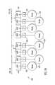
- FIG. 1is a schematic diagram of a braking system comprising an apparatus constituting an embodiment of the invention.
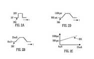
- FIGS. 2A to 2Dare schematic diagrams of signal and pressure profiles.
- a braking system 100comprises a source of hydraulic pressure 102 coupled to a Shut-Off Valve (SOV) 104 , the SOV 104 being coupled to a Pressure Control Unit (PCU) 106 .
- the PCU 106comprises a suitably programmed processing unit, which is schematically identified as the Electronic Control Unit 126 in FIG. 1A , coupled to a Utility Systems Management System (USMS) 110 via an input 108 .
- USMSUtility Systems Management System
- the programmed processing unitcan be replaced by other electronic circuitry and/or software.
- a hydraulic fluid output port 112is coupled to a first Brake Metering Valve (BMV) 114 and a second BMV 116 by a brake systems hydraulic line 113 , the first and second BMVs 114 , 116 being coupled to a first set of Anti-Skid Valves (ASVs) 118 and a second set of ASVs 120 , respectively.
- Each ASV 120is coupled to a corresponding brake assembly 122 via a respective hydraulic fuse 124 .
- the PCU 106comprises an Electronic Control Unit (ECU) 126 having an input constituting the input 108 of the PCU 106 , and an output coupled to an input of a Pressure Control Servovalve (PCS) 128 .
- the PCS 128has an input port 130 , constituting a hydraulic fluid input port of the PCU 106 , and an output port constituting the hydraulic fluid output port 112 .
- the ECU 126 and the PCS 128are formed as a single unit, namely the PCU 106 .
- the ECU 126 and PCS 128can be provided as separate units.
- a braking demandoriginates, for example, from a pilot.
- the braking demandis translated into an electrical braking demand signal.
- the braking demand signalis received by the USMS 110 in addition to other signals representative of factors pertinent to braking, for example: aircraft weight and/or speed.
- the USMS 110executes a number of algorithms in order to generate a brake trigger signal 200 ( FIG. 2A ) that is received by the ECU 126 via the input 108 .
- the PCU 106derives electrical power from the brake trigger signal 200 .
- the ECU 126processes the brake trigger signal 200 using a suitable control algorithm stored in the ECU 126 in order to generate a brake pressure demand signal 202 ( FIG. 2B ) that is received by the PCS 128 .
- the PCS 128actuates in accordance with the brake pressure demand signal 202 to apply pressure to the brake system hydraulic line 113 via the output port 112 ; the pressure profile applied to the braking system hydraulic line 113 follows a predetermined pressure vs. electrical input signal profile 204 ( FIG. 2C ) of the PCS 128 to yield a brake pressure 206 ( FIG. 2D ).
- the brake assemblies 202effect braking to slow the aircraft within acceptable mechanical parameters of the airframe of the aircraft, thereby avoiding compromising integrity of the airframe.
- the profile of the brake pressure demand signal 202can be easily modified by re-programming the ECU 126 and/or modifying at least one component of the ECU 126 .
- the ECU 126is programmed so that, irrespective of the brake demand made by the pilot, the translation of the brake demand by the pilot into the brake pressure 206 is overridden, when necessary, by the ECU 126 in order to avoid the profile of the brake pressure 206 deviating outside, or crossing one or more threshold corresponding to, predetermined pressure profile limits, thereby maintaining airframe integrity if the pilot issues an unacceptable braking demand.
Landscapes
- Engineering & Computer Science (AREA)
- Transportation (AREA)
- Mechanical Engineering (AREA)
- Aviation & Aerospace Engineering (AREA)
- Regulating Braking Force (AREA)
- Braking Systems And Boosters (AREA)
- Braking Arrangements (AREA)
- Control Of Fluid Pressure (AREA)
- Fluid-Pressure Circuits (AREA)
- Vehicle Body Suspensions (AREA)
Abstract
Description
Claims (9)
Priority Applications (1)
| Application Number | Priority Date | Filing Date | Title |
|---|---|---|---|
| US13/480,556US8393571B2 (en) | 2004-05-12 | 2012-05-25 | Hydraulic fluid control apparatus |
Applications Claiming Priority (3)
| Application Number | Priority Date | Filing Date | Title |
|---|---|---|---|
| GB0410620.9 | 2004-05-12 | ||
| GB0410620AGB2416009A (en) | 2004-05-12 | 2004-05-12 | Hydraulic fluid control apparatus |
| PCT/GB2005/001753WO2005110828A1 (en) | 2004-05-12 | 2005-05-10 | Hydraulic fluid control apparatus |
Publications (2)
| Publication Number | Publication Date |
|---|---|
| US20070210208A1 US20070210208A1 (en) | 2007-09-13 |
| US8205830B2true US8205830B2 (en) | 2012-06-26 |
Family
ID=32526932
Family Applications (2)
| Application Number | Title | Priority Date | Filing Date |
|---|---|---|---|
| US11/568,822Active2026-12-13US8205830B2 (en) | 2004-05-12 | 2005-05-10 | Hydraulic fluid control apparatus |
| US13/480,556ActiveUS8393571B2 (en) | 2004-05-12 | 2012-05-25 | Hydraulic fluid control apparatus |
Family Applications After (1)
| Application Number | Title | Priority Date | Filing Date |
|---|---|---|---|
| US13/480,556ActiveUS8393571B2 (en) | 2004-05-12 | 2012-05-25 | Hydraulic fluid control apparatus |
Country Status (8)
| Country | Link |
|---|---|
| US (2) | US8205830B2 (en) |
| EP (1) | EP1747129B1 (en) |
| AT (1) | ATE401222T1 (en) |
| CA (1) | CA2565156C (en) |
| DE (1) | DE602005008223D1 (en) |
| ES (1) | ES2310828T3 (en) |
| GB (1) | GB2416009A (en) |
| WO (1) | WO2005110828A1 (en) |
Families Citing this family (4)
| Publication number | Priority date | Publication date | Assignee | Title |
|---|---|---|---|---|
| US10088850B2 (en) | 2017-01-25 | 2018-10-02 | Goodrich Corporation | Brake pressure reducer valve with input pressure change compensation |
| GB2571100A (en)* | 2018-02-15 | 2019-08-21 | Airbus Operations Ltd | Controller for an aircraft braking system |
| US11548625B2 (en) | 2019-12-13 | 2023-01-10 | Goodrich Corporation | Aircraft brake system |
| FR3131721B1 (en)* | 2022-01-10 | 2023-11-24 | Psa Automobiles Sa | METHOD FOR MANAGING THE ELECTRIC POWER SUPPLY OF A BRAKE SYSTEM |
Citations (18)
| Publication number | Priority date | Publication date | Assignee | Title |
|---|---|---|---|---|
| US3948569A (en)* | 1973-09-05 | 1976-04-06 | Societe Nationale Industrielle Aerospatiale | Devices for controlling carbon disc brakes, more particularly for aircraft |
| US4043607A (en)* | 1975-02-07 | 1977-08-23 | Societe Nationale Industrielle Aerospatiale | Method and device for controlling disc brakes |
| US4412291A (en) | 1980-09-30 | 1983-10-25 | The Boeing Company | Brake torque control system |
| US4457967A (en)* | 1981-07-01 | 1984-07-03 | Le Carbone-Lorraine Of Tour Manhattan | Brake disc of carbon-carbon composite material |
| US4610484A (en) | 1983-09-23 | 1986-09-09 | The Boeing Company | Deceleration control brake system |
| US4775195A (en)* | 1986-10-25 | 1988-10-04 | Dunlop Limited | Hydraulic systems |
| EP0309074A2 (en) | 1987-09-21 | 1989-03-29 | Loral Corporation | Electrical brake pressure limiter and controller |
| US4822113A (en) | 1987-08-13 | 1989-04-18 | The Boeing Company | Braking torque control system |
| EP0329373A1 (en) | 1988-02-16 | 1989-08-23 | Dunlop Limited | Aircraft braking systems |
| US5081297A (en)* | 1986-05-06 | 1992-01-14 | Grumman Aerospace Corporation | Software reconfigurable instrument with programmable counter modules reconfigurable as a counter/timer, function generator and digitizer |
| US5180214A (en)* | 1991-12-30 | 1993-01-19 | National Science Council | Servo-type phase-locked loop anti-skid brake control system |
| EP0936116A2 (en) | 1998-02-12 | 1999-08-18 | The B.F. Goodrich Company | Brake control systems and methods |
| US6068212A (en)* | 1996-12-18 | 2000-05-30 | British Aerospace Public Limited Company | Aircraft structure and powerplants for use therein |
| EP1080009B1 (en) | 1999-05-14 | 2002-12-18 | Hydro-Aire, Inc. | Dual redundant active/active brake-by-wire architecture |
| US7252263B1 (en)* | 2004-07-29 | 2007-08-07 | Hawker Beechcraft Corporation | Design methods and configurations for supersonic aircraft |
| US20100170995A1 (en)* | 2005-08-17 | 2010-07-08 | Airbus Deutschland Gmbh | Support structure for a wing |
| US7786937B1 (en)* | 2005-09-27 | 2010-08-31 | Comant Industries, Inc. | Multi-operational combination aircraft antennas |
| US20100288244A1 (en)* | 2007-11-14 | 2010-11-18 | Airbus Operations Sas | Method for controlling thermal effluents generated by an aircraft and cooling device for an aircraft implementing said method |
- 2004
- 2004-05-12GBGB0410620Apatent/GB2416009A/ennot_activeWithdrawn
- 2005
- 2005-05-10EPEP05746393Apatent/EP1747129B1/ennot_activeExpired - Lifetime
- 2005-05-10CACA2565156Apatent/CA2565156C/ennot_activeExpired - Lifetime
- 2005-05-10USUS11/568,822patent/US8205830B2/enactiveActive
- 2005-05-10ESES05746393Tpatent/ES2310828T3/ennot_activeExpired - Lifetime
- 2005-05-10ATAT05746393Tpatent/ATE401222T1/ennot_activeIP Right Cessation
- 2005-05-10WOPCT/GB2005/001753patent/WO2005110828A1/enactiveIP Right Grant
- 2005-05-10DEDE602005008223Tpatent/DE602005008223D1/ennot_activeExpired - Lifetime
- 2012
- 2012-05-25USUS13/480,556patent/US8393571B2/enactiveActive
Patent Citations (18)
| Publication number | Priority date | Publication date | Assignee | Title |
|---|---|---|---|---|
| US3948569A (en)* | 1973-09-05 | 1976-04-06 | Societe Nationale Industrielle Aerospatiale | Devices for controlling carbon disc brakes, more particularly for aircraft |
| US4043607A (en)* | 1975-02-07 | 1977-08-23 | Societe Nationale Industrielle Aerospatiale | Method and device for controlling disc brakes |
| US4412291A (en) | 1980-09-30 | 1983-10-25 | The Boeing Company | Brake torque control system |
| US4457967A (en)* | 1981-07-01 | 1984-07-03 | Le Carbone-Lorraine Of Tour Manhattan | Brake disc of carbon-carbon composite material |
| US4610484A (en) | 1983-09-23 | 1986-09-09 | The Boeing Company | Deceleration control brake system |
| US5081297A (en)* | 1986-05-06 | 1992-01-14 | Grumman Aerospace Corporation | Software reconfigurable instrument with programmable counter modules reconfigurable as a counter/timer, function generator and digitizer |
| US4775195A (en)* | 1986-10-25 | 1988-10-04 | Dunlop Limited | Hydraulic systems |
| US4822113A (en) | 1987-08-13 | 1989-04-18 | The Boeing Company | Braking torque control system |
| EP0309074A2 (en) | 1987-09-21 | 1989-03-29 | Loral Corporation | Electrical brake pressure limiter and controller |
| EP0329373A1 (en) | 1988-02-16 | 1989-08-23 | Dunlop Limited | Aircraft braking systems |
| US5180214A (en)* | 1991-12-30 | 1993-01-19 | National Science Council | Servo-type phase-locked loop anti-skid brake control system |
| US6068212A (en)* | 1996-12-18 | 2000-05-30 | British Aerospace Public Limited Company | Aircraft structure and powerplants for use therein |
| EP0936116A2 (en) | 1998-02-12 | 1999-08-18 | The B.F. Goodrich Company | Brake control systems and methods |
| EP1080009B1 (en) | 1999-05-14 | 2002-12-18 | Hydro-Aire, Inc. | Dual redundant active/active brake-by-wire architecture |
| US7252263B1 (en)* | 2004-07-29 | 2007-08-07 | Hawker Beechcraft Corporation | Design methods and configurations for supersonic aircraft |
| US20100170995A1 (en)* | 2005-08-17 | 2010-07-08 | Airbus Deutschland Gmbh | Support structure for a wing |
| US7786937B1 (en)* | 2005-09-27 | 2010-08-31 | Comant Industries, Inc. | Multi-operational combination aircraft antennas |
| US20100288244A1 (en)* | 2007-11-14 | 2010-11-18 | Airbus Operations Sas | Method for controlling thermal effluents generated by an aircraft and cooling device for an aircraft implementing said method |
Non-Patent Citations (1)
| Title |
|---|
| International Search Report dated Aug. 29, 2005 for Application No. PCT/GB2005/001753. |
Also Published As
| Publication number | Publication date |
|---|---|
| US8393571B2 (en) | 2013-03-12 |
| ATE401222T1 (en) | 2008-08-15 |
| GB2416009A (en) | 2006-01-11 |
| EP1747129A1 (en) | 2007-01-31 |
| US20120286564A1 (en) | 2012-11-15 |
| CA2565156C (en) | 2012-10-23 |
| WO2005110828A1 (en) | 2005-11-24 |
| CA2565156A1 (en) | 2005-11-24 |
| EP1747129B1 (en) | 2008-07-16 |
| ES2310828T3 (en) | 2009-01-16 |
| US20070210208A1 (en) | 2007-09-13 |
| GB0410620D0 (en) | 2004-06-16 |
| DE602005008223D1 (en) | 2008-08-28 |
Similar Documents
| Publication | Publication Date | Title |
|---|---|---|
| US8393571B2 (en) | Hydraulic fluid control apparatus | |
| EP1957335B1 (en) | Device for the processing of compressed air, and method for the operation thereof | |
| EP3851344B1 (en) | Staged method to detect brake fail conditions in brake control systems | |
| DE112009002349B4 (en) | Brake control device | |
| US9387840B1 (en) | Multi-thread emergency park brake system | |
| JP5508455B2 (en) | Aircraft hydraulic brake structure for braking at least one wheel of an aircraft | |
| CA2849851C (en) | Brake control device and brake control method | |
| EP3835149B1 (en) | Aircraft brake system | |
| EP3279045B1 (en) | Systems and methods for brake control | |
| EP3700788B1 (en) | Axle valve module and relay valve module for a pneumatic brake system | |
| US11400951B2 (en) | Control system for a motor vehicle, motor vehicle, method for controlling a motor vehicle, computer program product and computer-readable medium | |
| US20090004027A1 (en) | Ventilation of an Operating Element | |
| WO2010051920A3 (en) | Method and system for emergency ventilation of an aircraft cabin | |
| DE102009059811B3 (en) | Multi-channel pressure control module with only one pressure sensor | |
| WO2024179841A1 (en) | Valve assembly for a pneumatic system of a vehicle, in particular a commercial vehicle, pneumatic system, vehicle, in particular commercial vehicle, method and computer program and/or computer-readable medium | |
| US20090024290A1 (en) | Method of controlling a vehicle brake with torque correction | |
| CN111792025A (en) | Method for controlling a brake system | |
| US20050194495A1 (en) | Aircraft landing gear | |
| EP3402704B1 (en) | Brake pressure switchover with continuous-time ramp for rail vehicles | |
| EP1646545B1 (en) | Braking device for a rail vehicle | |
| CN111186425A (en) | Brake system for a motor vehicle and method for operating a brake system | |
| US11052884B2 (en) | Braking control for rail vehicles with adaptive lining characteristic curve | |
| CA2580276A1 (en) | Mechanical flight control auxiliary power assist system | |
| WO2016116416A1 (en) | Brake control device for a hydraulic motor vehicle brake system, and brake system having an arrangement of said type | |
| KR101714245B1 (en) | Apparatus for preventing increase of oil pressure in wheel due to oil leak at valve when ESC is started and method for controlling the same |
Legal Events
| Date | Code | Title | Description |
|---|---|---|---|
| AS | Assignment | Owner name:DUNLOP AEROSPACE LIMITED, UNITED KINGDOM Free format text:ASSIGNMENT OF ASSIGNORS INTEREST;ASSIGNOR:MILLER, RICHARD JOHN;REEL/FRAME:019199/0822 Effective date:20070404 | |
| AS | Assignment | Owner name:MEGGITT AEROSPACE LIMITED, UNITED KINGDOM Free format text:CHANGE OF NAME;ASSIGNOR:DUNLOP AEROSPACE LIMITED;REEL/FRAME:020794/0906 Effective date:19971209 Owner name:MEGGITT AEROSPACE LIMITED,UNITED KINGDOM Free format text:CHANGE OF NAME;ASSIGNOR:DUNLOP AEROSPACE LIMITED;REEL/FRAME:020794/0906 Effective date:19971209 | |
| AS | Assignment | Owner name:MEGGITT AEROSPACE LIMITED, UNITED KINGDOM Free format text:CORRECTIVE NAME CHANGE. THE NAME CHANGE (PREVIOUSLY RECORDED AT REEL/FRAME 020794/0906 ON APRIL 15, 2008) USED AN INCORRECT EXECUTION DATE OF DECEMBER 9, 1997. THE CORRECT EXECUTION DATE SHOULD BE JANUARY 4, 2008.;ASSIGNOR:DUNLOP AEROSPACE LIMITED;REEL/FRAME:021876/0456 Effective date:20080104 Owner name:MEGGITT AEROSPACE LIMITED,UNITED KINGDOM Free format text:CORRECTIVE NAME CHANGE. THE NAME CHANGE (PREVIOUSLY RECORDED AT REEL/FRAME 020794/0906 ON APRIL 15, 2008) USED AN INCORRECT EXECUTION DATE OF DECEMBER 9, 1997. THE CORRECT EXECUTION DATE SHOULD BE JANUARY 4, 2008;ASSIGNOR:DUNLOP AEROSPACE LIMITED;REEL/FRAME:021876/0456 Effective date:20080104 Owner name:MEGGITT AEROSPACE LIMITED, UNITED KINGDOM Free format text:CORRECTIVE NAME CHANGE. THE NAME CHANGE (PREVIOUSLY RECORDED AT REEL/FRAME 020794/0906 ON APRIL 15, 2008) USED AN INCORRECT EXECUTION DATE OF DECEMBER 9, 1997. THE CORRECT EXECUTION DATE SHOULD BE JANUARY 4, 2008;ASSIGNOR:DUNLOP AEROSPACE LIMITED;REEL/FRAME:021876/0456 Effective date:20080104 | |
| STCF | Information on status: patent grant | Free format text:PATENTED CASE | |
| FPAY | Fee payment | Year of fee payment:4 | |
| MAFP | Maintenance fee payment | Free format text:PAYMENT OF MAINTENANCE FEE, 8TH YEAR, LARGE ENTITY (ORIGINAL EVENT CODE: M1552); ENTITY STATUS OF PATENT OWNER: LARGE ENTITY Year of fee payment:8 | |
| MAFP | Maintenance fee payment | Free format text:PAYMENT OF MAINTENANCE FEE, 12TH YEAR, LARGE ENTITY (ORIGINAL EVENT CODE: M1553); ENTITY STATUS OF PATENT OWNER: LARGE ENTITY Year of fee payment:12 |