US8205703B2 - Deformable modular armored combat system - Google Patents
Deformable modular armored combat systemDownload PDFInfo
- Publication number
- US8205703B2 US8205703B2US12/344,630US34463008AUS8205703B2US 8205703 B2US8205703 B2US 8205703B2US 34463008 AUS34463008 AUS 34463008AUS 8205703 B2US8205703 B2US 8205703B2
- Authority
- US
- United States
- Prior art keywords
- module
- ccm
- engine
- vehicle
- driver
- Prior art date
- Legal status (The legal status is an assumption and is not a legal conclusion. Google has not performed a legal analysis and makes no representation as to the accuracy of the status listed.)
- Expired - Fee Related, expires
Links
- 239000000446fuelSubstances0.000claimsdescription12
- 238000004880explosionMethods0.000claimsdescription10
- 238000012423maintenanceMethods0.000claimsdescription3
- 230000008439repair processEffects0.000claimsdescription3
- 239000011521glassSubstances0.000claimsdescription2
- 229920000642polymerPolymers0.000claimsdescription2
- 238000010276constructionMethods0.000claims1
- 238000013461designMethods0.000description21
- 230000008878couplingEffects0.000description7
- 238000010168coupling processMethods0.000description7
- 238000005859coupling reactionMethods0.000description7
- 230000006870functionEffects0.000description6
- 230000008901benefitEffects0.000description4
- 230000021715photosynthesis, light harvestingEffects0.000description4
- 239000000725suspensionSubstances0.000description4
- 230000000712assemblyEffects0.000description3
- 238000000429assemblyMethods0.000description3
- 239000000428dustSubstances0.000description3
- 239000000463materialSubstances0.000description3
- 230000000717retained effectEffects0.000description3
- 238000013022ventingMethods0.000description3
- RTZKZFJDLAIYFH-UHFFFAOYSA-NDiethyl etherChemical compoundCCOCCRTZKZFJDLAIYFH-UHFFFAOYSA-N0.000description2
- 230000001133accelerationEffects0.000description2
- 230000005540biological transmissionEffects0.000description2
- 239000002131composite materialSubstances0.000description2
- 238000001816coolingMethods0.000description2
- 230000000694effectsEffects0.000description2
- 239000002360explosiveSubstances0.000description2
- 239000002828fuel tankSubstances0.000description2
- 238000004519manufacturing processMethods0.000description2
- 230000035939shockEffects0.000description2
- 210000000278spinal cordAnatomy0.000description2
- 238000012546transferMethods0.000description2
- 239000013585weight reducing agentSubstances0.000description2
- 206010039203Road traffic accidentDiseases0.000description1
- XAGFODPZIPBFFR-UHFFFAOYSA-NaluminiumChemical compound[Al]XAGFODPZIPBFFR-UHFFFAOYSA-N0.000description1
- 229910052782aluminiumInorganic materials0.000description1
- 230000004888barrier functionEffects0.000description1
- 238000002485combustion reactionMethods0.000description1
- 239000012141concentrateSubstances0.000description1
- 238000011109contaminationMethods0.000description1
- 239000002283diesel fuelSubstances0.000description1
- 239000003814drugSubstances0.000description1
- 229940079593drugDrugs0.000description1
- 238000010304firingMethods0.000description1
- 239000003517fumeSubstances0.000description1
- 239000003502gasolineSubstances0.000description1
- 230000005484gravityEffects0.000description1
- 238000005259measurementMethods0.000description1
- 230000007246mechanismEffects0.000description1
- 238000000034methodMethods0.000description1
- 238000012986modificationMethods0.000description1
- 230000004048modificationEffects0.000description1
- 230000035515penetrationEffects0.000description1
- 230000001681protective effectEffects0.000description1
- 238000011160researchMethods0.000description1
- 230000004044responseEffects0.000description1
- 238000000926separation methodMethods0.000description1
- 230000004083survival effectEffects0.000description1
- 230000001131transforming effectEffects0.000description1
Images


Classifications
- F—MECHANICAL ENGINEERING; LIGHTING; HEATING; WEAPONS; BLASTING
- F41—WEAPONS
- F41H—ARMOUR; ARMOURED TURRETS; ARMOURED OR ARMED VEHICLES; MEANS OF ATTACK OR DEFENCE, e.g. CAMOUFLAGE, IN GENERAL
- F41H7/00—Armoured or armed vehicles
- F41H7/02—Land vehicles with enclosing armour, e.g. tanks
- F41H7/04—Armour construction
- F41H7/048—Vehicles having separate armoured compartments, e.g. modular armoured vehicles
- B—PERFORMING OPERATIONS; TRANSPORTING
- B62—LAND VEHICLES FOR TRAVELLING OTHERWISE THAN ON RAILS
- B62D—MOTOR VEHICLES; TRAILERS
- B62D63/00—Motor vehicles or trailers not otherwise provided for
- B62D63/02—Motor vehicles
- B62D63/025—Modular vehicles
- F—MECHANICAL ENGINEERING; LIGHTING; HEATING; WEAPONS; BLASTING
- F41—WEAPONS
- F41H—ARMOUR; ARMOURED TURRETS; ARMOURED OR ARMED VEHICLES; MEANS OF ATTACK OR DEFENCE, e.g. CAMOUFLAGE, IN GENERAL
- F41H7/00—Armoured or armed vehicles
- F41H7/02—Land vehicles with enclosing armour, e.g. tanks
- F41H7/04—Armour construction
- F41H7/042—Floors or base plates for increased land mine protection
- F—MECHANICAL ENGINEERING; LIGHTING; HEATING; WEAPONS; BLASTING
- F41—WEAPONS
- F41H—ARMOUR; ARMOURED TURRETS; ARMOURED OR ARMED VEHICLES; MEANS OF ATTACK OR DEFENCE, e.g. CAMOUFLAGE, IN GENERAL
- F41H7/00—Armoured or armed vehicles
- F41H7/02—Land vehicles with enclosing armour, e.g. tanks
- F41H7/04—Armour construction
- F41H7/044—Hull or cab construction other than floors or base plates for increased land mine protection
- F—MECHANICAL ENGINEERING; LIGHTING; HEATING; WEAPONS; BLASTING
- F41—WEAPONS
- F41A—FUNCTIONAL FEATURES OR DETAILS COMMON TO BOTH SMALLARMS AND ORDNANCE, e.g. CANNONS; MOUNTINGS FOR SMALLARMS OR ORDNANCE
- F41A23/00—Gun mountings, e.g. on vehicles; Disposition of guns on vehicles
- F41A23/34—Gun mountings, e.g. on vehicles; Disposition of guns on vehicles on wheeled or endless-track vehicles
- F41A23/42—Gun mountings, e.g. on vehicles; Disposition of guns on vehicles on wheeled or endless-track vehicles for rocket throwers
Definitions
- the present disclosurerelates to motorized vehicles suitable for military use and more particularly to a modular military vehicle that can be adapted for non-military uses.
- a multi-purpose vehiclesuitable for military, homeland security, disaster/emergency response, and other uses, should be versatile. It should be able to protect the operators and be highly deliverable to any site, adaptable, maintainable, and agile. Also, it should be armored and operable over rugged terrain and hostile environments, including, for example, desert and frigid conditions. Such vehicle further should be highly maneuverable.
- the disclosed modular vehicleis compartmentalized through modular, severable, frangible sub-systems or components with a view to isolating effects of ballistic, shock/blast and other undesirable kinetic forces.
- Modularityincludes a central driver module and engine module, which form a central chassis module or CCM.
- the driver moduleis capable of carrying, for example, 1 to 3 people, and can be common in design regardless of function and/or use. Pods, then, can be attached to the central module to provide different functions including, for example, troop carrier, ambulance, cargo, etc. Such design allows the army to transport pods and not fully dedicated (i.e., single use) vehicles.
- the engine modulebolts directly to the central driver module as a complete unit. Pods are more readily transported to other field areas of need, so long as at the new site has the means to attach/detach such pods to the CCM.
- the CCM and side podspresent three V-shaped hulls on their underside.
- Such a blast-deflecting design along with side pod frangibility and engine module open frameworkshould significantly increase the venting of the blast reducing the penetration and deformation of the area where people are sitting.
- the smallest flat area facing the groundnow can be less than about 10 inches (25.4 cm) in width.
- Engine and gearbox togetherare separate and located to the rear of the driver module. This design isolates heat, noise, fumes etc., from the driver module and personnel therein significantly increasing the ability of the occupants to perform their duty when they leave the vehicle.
- the relatively common cross-sectional shape of all modulesallows for a design that is very simple to manufacture.
- the detachable rear bulkhead of the driver module and troop carrying podsallows for ease of fitting a spall liner, the shrapnel anti intrusion layer, inside the vehicle. Because of this removable bulkhead, the spall liner can be large in size improving its ability to counter intrusion of shrapnel.
- the narrow engine module designallows for ease of maintenance of the engine, because of a closer proximity to the engine components by technicians working on the engine/gearbox section. It is intended that this engine module be manufactured with a tubular frame allowing significant blast venting between the two-crew side modules increasing survivability of the crew. Placing the engine/drive module in the center of the vehicle reduces the possibility of these components being damaged and disabling the vehicle with small arms fire. By simply creating small top and rear armored panels these drive elements become well protected. In summary, this engine/drive placement allows excellent blast venting and provides good small arms fire protection.
- the air inlet ductis located above the vehicle and is retractable in case the vehicle needs to be transported, for example, in a marine vessel (76′′ or 1.93 m) height. Locating the cooling and engine air inlet high allows for less contamination of air with dust, and when using the vehicle in hot environments this high inlet position allows the air temperature to the cooling systems to be substantially lower than using air adjacent to the road surface, etc.
- the podscan be designed to swing out either in a parallel fashion or in a door fashion incorporating as well a frangible system or the pods can be attached in such a way with a 4 bar linkage the pods can merely be located to the CCM by means of the clip system later disclosed (See FIG. 6A ) —all methods can become detached by fracture of a frangible fastening device.
- 4-wheel driveis achieved by passing the driveshaft under or beside the engine and personnel seated in the CCM to the differential housing located under the driver in the driver module. This may require the addition of a two or three shaft oblique transfer module that allows minimization of driveshaft angle. This oblique transfer module can be placed at the interface between the driver and engine modules.
- the basic designadmits of carrying from 1 to 7 people. Additional crew can be carried in additional pods at the rear of the CCM.
- the wheelbasecan be lengthened, by about 30′′ (106.2 cm) by extending the rear central module or the driver module. The pods similarly then can be increased and an extra person can be included in each pod; thus, increasing the total vehicle capacity to 9 people instead of 7.
- Increasing the wheelbase by 30′′ (106.2 cm)also allows an alternate ambulance ‘low rise’ side pod to be fitted in between the wheels, allowing transportability in a 76′′ (1.93 m) height.
- the conceptcan be used as a 3-person carrier by reducing the CCM front to a single person with single person pods; thus, allowing substantial carrying capacity rear of the engine area.
- Each person in the vehiclefurther can be fitted with a helmet protective collar, such as is used in high speed automobile racing, to help reduce acceleration effects on the lower neck during an explosion.
- the occupantscan wear an extended rear ballistic panel (SAPI panels—small arms protection inserts) to allow for increased protection and also to act as helmet support (with straps) to avoid the possible separation of the top spinal cord in the event of extreme accelerations on the head relative to the body.
- SAPI panelssmall arms protection inserts
- helmet supportwith straps
- Typical US pickupsare adaptable as multi-use vehicles carrying 4 to 5 people and cargo.
- the disclosed modular vehicleachieves such uses with a side-to-side split of functionality. That is, the modular vehicle has a CCM capable of carrying 2 people and which is common in all configurations.
- the side podswhich attach to this CCM, have different functions including, for example, carrying people in people pod on a single side or both, carrying cargo in pods that are relatively low to the ground and tall in height, sleeping pods, etc.
- the commercial modular vehiclecan include 4-wheel drive.
- the central podcan be narrow and aerodynamic with aerodynamic suspension attachment legs and wheel aerodynamic pods to reduce drag.
- the rear aerodynamic podscan be removed when adding any side pod, which also will incorporate an aerodynamic covered surface.
- FIG. 1is an isometric view of the modular military vehicle carrying a pair of side, personnel pods and 3 cantilevered cargo pods;
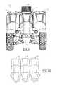
- FIG. 2is a front view of the modular military vehicle of FIG. 1 ;
- FIG. 2Ais a simplified schematic view of the modular military vehicle of FIG. 2 showing the blast energy dissipation paths resulting from the design of the bottoms of the modules;
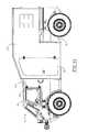
- FIG. 3is a side view of the modular military vehicle of FIG. 1 ;
- FIG. 4is an overhead view of the modular military vehicle of FIG. 1 ;
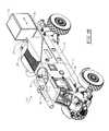
- FIG. 5is an underside view of the modular military vehicle of FIG. 1 ;
- FIG. 6is a front view like that in FIG. 1 with the side pods deployed;
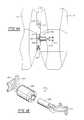
- FIG. 6Ais an enlarged view of the frangible coupling system of the side pods to the CCM
- FIG. 6Bis an isometric of the shock absorbed element of the frangible coupling system depicted in FIG. 6A ;
- FIG. 7is an underside view of the pod-deployed vehicle in FIG. 6 ;
- FIG. 7Ais an isometric view of one of the tether assemblies seen in FIG. 7 ;
- FIG. 7Bis a side view of the tether assembly shown in FIG. 7B ;
- FIG. 8is a side view of the modular military vehicle of FIG. 1 showing seated personnel, engine, and the like in phantom;
- FIG. 9is an isometric view of the modular military vehicle fitted with ambulance side pods
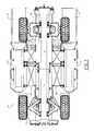
- FIG. 10is a front view of the modular ambulance vehicle of FIG. 9 ;
- FIG. 11is a side view of the modular ambulance vehicle of FIG. 9 ;
- FIG. 12is a top view of the modular ambulance vehicle of FIG. 9 ;
- FIG. 13is a rear isometric view of the modular ambulance vehicle of FIG. 9 ;
- FIG. 14is an isometric view of the modular military vehicle with only 1 side pod, but with a rear personnel pod;
- FIG. 15is a sectional view taken along line 15 - 15 of FIG. 12 ;
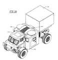
- FIG. 16is an isometric view of the modular military vehicle fitted with cargo side pods
- FIG. 17is a rear view of the modular cargo vehicle of FIG. 16 ;
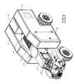
- FIG. 18is an isometric view of the modular military vehicle without side pods, but fitted with top-mounted armament and a movable rear storage module;
- FIG. 19is an isometric view of the modular military vehicle fitted with side armament that includes missiles, and a rear storage module for carrying, for example, extra armament, missiles, or the like;
- FIG. 20is an isometric view of a side pod transport for conveying electrical generators and fuel drums
- FIG. 21is an isometric view of a side pod transport configured as a storage cabinet
- FIG. 22is an isometric side view of the modular military vehicle adapted as a fuel tanker by configuring with side and rear fuel tanks;
- FIG. 23is an isometric view of a side pod configured to convey 3 soldiers
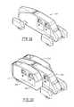
- FIG. 24is an isometric view of the short wheelbase modular military vehicle with a pair of single soldier side pods, a single drive CCM module and a rear shelter;
- FIG. 25is the short wheelbase shelter modular military vehicle of FIG. 24 with no soldier side pods;
- FIG. 26is an isometric view of another modular military vehicle embodiment having a one-person driver module, side pods for soldiers, and a rear cargo shelter;
- FIG. 27is an overhead view of another modular military vehicle embodiment designed only for troop transport;
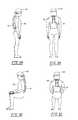
- FIG. 28is a side isometric view of a standing soldier (medic from FIG. 15 ) fitted with a SAPI (small arms protection inserts) panel affixed to his helmet;
- SAPIsmall arms protection inserts
- FIG. 29is a rear view of the medic of FIG. 28 showing the back-carried SAPI unit
- FIG. 30is a side view of the medic seated, but still wearing the extended SAPI unit
- FIG. 31is a rear view of the seated medic of FIG. 30 ;
- FIG. 32is an isometric view of a streamlined modular passenger vehicle without side pods
- FIG. 33is an isometric view of a streamlined modular passenger vehicle with side passenger pods
- FIG. 34is an isometric view of a streamlined camping modular vehicle with side pods
- FIG. 35is an isometric view of a streamlined passenger modular vehicle with cargo side pods
- FIG. 36is an isometric view of a troop carrier embodiment of the modular military vehicle having an enlarged driver module suitable for up to, for example, 3 troops to occupy, troop side pods, and rear troop pod;
- FIG. 37is an isometric view of a troop carrier embodiment of the modular military vehicle with enlarged driver module, troop side pods, and rear storage pod.
- the disclosed modular vehicleprimarily is designed for military use. For such use, however, the modular vehicle needs to be readily transported by air (e.g., cargo plane, helicopter, etc.) to remote hostile territory; withstand explosive blasts, bullets, and like insults; be easy to maintain and repair; readily convertible for cargo use, troop transport, wounded soldier (ambulance) transport; provide cover and support for ground soldier advancement; and the like.
- aire.g., cargo plane, helicopter, etc.
- the disclosed modular vehicleaccomplishes each of these tasks and more, as the skilled artisan will appreciate based on the present disclosure. Its design flexibility further enables the disclosed modular vehicle to be adapted for passenger use, civilian ambulance use, civilian cargo use, and the like.
- a modular military vehicle, 10is shown to include a central chassis module or CCM, 12 (see FIG. 18 ), composed to a driver module, 14 , and an engine module, 16 .
- Vehicle 10also includes two side pods, 18 and 20 , and three rear pods, 22 , 24 , and 26 . Equally these three pods could be a single pod across the rear of the vehicle.
- side pods 18 and 20carry personnel, while rear pods 22 , 24 , and 26 carry cargo.
- Vehicle suspension, steering, wheels/tires, transmission, headlights, windows (glass or polymer, often bullet-proof), and the likewill be provided in conventional fashion adapted to the intended use of vehicle 10 .
- Driver module 14 and side modules 18 and 20all are fitted with doors, such as doors, 28 and 30 , on side pod 18 , and a door, 32 , on driver module 14 , for ingress and egress of personnel.
- Driver module 14is adapted for in-line front-to-back seating of two personnel with the driver entering module 14 through door 32 and the rear personnel entering module 14 via an overhead opening, 34 or through door 32 without the driver in position and the driver seat having the capacity to tilt forward.
- Access to cargo modules 22 , 24 , and 26can be gained by side or rear doors, such as, for example, a side door, 36 , for module 22 .
- driver module 14has a rear bulkhead to allow for ease of building the internal elements of the module 14 .
- a retractable/extendable engine air inlet, 38is seen in an extended position from the top of engine module 16 (two engine configuration forms shown in FIG. 1 and FIG. 9 ).
- Air inlet 38can be retracted or removed. Its location atop modular vehicle 10 keeps it above much of the dust created by vehicle 10 and events occurring on the ground in the vicinity of vehicle 10 .
- An exhaust port, 37for the engine exhaust is disposed rearward of air inlet 38 or air can exit down over the engine and exit via holes at the rear of the CCM rear engine module.
- a grate, 39allows air to exit the engine compartment. Not only will be air be cleaner atop vehicle 10 , but it will be cooler than air next to or underneath vehicle 10 particularly when in a hot environment.
- air inlet and exhaust portsalso could be located in the sides of engine module 16 close to the top and these same benefits realized.
- the air inlet and/or exhaust portsare located “about the top” of the engine module by being located in the top of the module or in a side of the module very close to the top thereof.
- each modulecan be designed with upward slanting sides to aid in deflecting any blasts occurring from underneath modular military vehicle 10 to minimize damage.
- a blast energy dissipation pattern, 1(see FIG. 6A ) for driver module 14 ; a blast energy dissipation pattern, 2 , for side module 18 ; and a blast energy dissipation pattern, 3 , for side module 20 , show the blast energy being diverted around the sides of the modules to lessen damage to the components of vehicle 10 .
- Such pattern along with side modules 18 and 20 that can be controllably blown away from CCM 12will help in minimizing vehicle damage from blasts occurring underneath virtually any area beneath vehicle 10 .
- side pods 18 and 20are seen in partially deployed condition up and away from CCM 12 using hydraulic pistons and supporting strut assemblies, 40 and 42 , which are conventional in design and operation.
- Deployment of side pods 18 and 20enjoys several advantages, including, inter alia, reducing the footprint size subject to road explosions, adding increasing distance from ground blasts, isolating pods subject to damage from blasts and explosions, and providing foot soldier protection between the side pods and CCM 12 (potentially with platforms that deploy for the soldiers to stand on upon deployment of the side pods).
- the blast deflecting bottom designalso is seen to include a small horizontal flat or V bottom with angled flat sections that extend upwards. Such design presents a minimal footprint to explosions.
- the slanted sections and space created between the deployed side pods and CCM 12deflect the brunt of the explosive force upwards away from the vehicle to minimize damage.
- the modular designpermits any damaged pod to be readily replaced in the field and the vehicle put back in operation.
- the hydraulic system for deploying the side pods or modulesalso could be adapted to move the side pods from an operating position adjacent to the CCM to the ground for removing the side pods and from the ground to an operating position.
- the hydraulic systemcould be adapted for putting on and taking off the side pods from the DMACS.
- the troop side pod coupling to the central elementis “frangible”, permitting the side pod to be dislodged by the explosion. It is thought that, to absorb some of the energy of the blast explosion, it is possible that a damper can be placed between the side pod and the CCM as part of the frangible system. The addition of this dampening mechanism may allow the pod to still remain attached to the CCM without breaking the frangible coupling.
- interlocking bracket assembly 201is composed of a pair of “L” brackets, 213 and 215 , which are retained in interlocked relationship by gravity.
- attenuating assembly 203(such as a cylinder assembly) is composed of a cylinder, 205 , associated bracket, 207 , a handle, 213 , and interlining rod, 209 , and associated bracket, 211 .
- Hooking a side module to the CCMis quick and easy by dint of the design of the frangible coupling assembly.
- Handle 213is rotatable to cause pressure from cylinder 205 to be exerted on inserted rod 209 . This ensures that the side module will stay attached during travel, such as, for example, over rough roads. The force of a blast, however, will cause rod 209 to withdraw from cylinder 205 and the tethers will limit the distance of travel of the dislodged module.
- the troop side podalso can be retained to the CCM by means of tether assemblies (see also FIGS. 7A and 7B ), 41 and 43 , whose ends are retained on both the CCM and the side pod by brackets, 45 and 47 .
- the straps, 49most likely will be in the form of webbing having a degree of elasticity and stitched together in a snaked or accordion pattern so that when the pod moves away from the CCM the stitching is broken as the tether unfolds.
- the frangible coupling assembly and tetherare able to further absorb some of the explosion energy during an explosion, say, beneath the vehicle.
- the cylinder assemblypulls apart with some force as is typical for a cylinder and rod assembly, and by the ether stretching in much the same way that seat belts absorb energy during an accident.
- the podsin order for the pods not to decelerate too violently at the end of the straps, most likely some elasticity will be incorporated into the straps.
- at least one pair of straps(for example, 3 pairs per side module) can used for each side pod. This number is arbitrary and could be greater or lesser in number.
- FIG. 8Personnel, 44 and 46 , seated in driver module 14 are seen in FIG. 8 . Also seen is an engine, 48 , a radiator, 50 , and a exhaust assembly, 52 . Air for engine 48 and to cool radiator 50 is admitted through grate 38 . Exhaust passed through exhaust assembly 52 passes to the atmosphere through port 37 . Fresh air for personnel 44 and 46 is admitted via air inlets 38 on each side of the CCM above the engine ( FIG. 14 rectangular hole above engine module 16 ). As observed earlier, locating the air inlets and exhaust atop vehicle 10 will minimize dust entry into vehicle 10 . A presently preferred engine/radiator configuration, however, is illustrated in FIG. 14 .
- litter pods, 52 and 54have been attached to CCM 12 to create a modular ambulance.
- CCM 12remains unchanged from the previous drawings, except for an air intake, 38 ′, and exhaust, 37 ′.
- Litter pods 52 and 54may or may not be deployable.
- Litter pod 52is fitted with a door, 56
- litter pod 54also is fitted with a door, 58 (see FIG. 13 ).
- Medic personnelcan enter litter pods 52 and 54 through doors 56 and 58 .
- Wounded soldierscan be placed in litter pods 52 and 54 conveniently through rear access openings in litter pods 52 and 54 , such as is illustrated in FIG. 13 . Doors, netting, or other restrictions will be provided to keep the litters in litter pods 52 and 54 .
- a medic, 60is seen in medic pod 52 where he can attend to the needs of wounded soldiers on litters, 68 and 70 , or can be seated on a seat, 62 .
- a storage bin, 64is provided to house medicines, instruments, and like items.
- Medic 60is fitted a SAPI panel, 61 , affixed to his helmet, 63 .
- Personnel 44 and 46 seated in driver module 14also could be fitted with a SAPI panel, as, indeed, could any personnel confined within military module vehicle 10 .
- FIGS. 28-31illustrate medic 60 again, standing and sitting.
- SAPI panel 61is seen affixed to helmet 63 in addition to medic 60 , regardless of whether in a seated or standing position.
- Such extended panel 61 from the SAPI packwill be secured with, for example, Velcro® into position within the soldier's ballistic vest and with the soldiers' ballistic collar. It is thought that a pivot at the top of this extended SAPI panel should be incorporated to allow the head to be turned easily and with comfort.
- module 24is a personnel module for carrying an additional medic, 72 , which can treat the legs and lower torso of the wounded soldiers.
- an access, 74is created in module 24 that mates with a similar access, 76 , in module 52 . Similar accesses are provided for medic 72 to treat wounded soldiers in module 54 .
- CCM 12is illustrated in FIG. 18 .
- a portable missile launcher, 96is disposed atop driver module 14 and is desirably controlled by personnel 46 , so that driver 44 can concentrate on driving CCM 12 .
- Module 24is mounted on rails, such as a rail, 25 , and another rail on the far side of CCM 12 that is not seen in FIG. 18 . Moving module 24 rearwardly away from CCM 12 also permits repair/maintenance access to the engine in engine module 16 and to the transmission and other drive train elements disposed therein. A cover conveniently at the rear of CCM 12 , for example, could be opened to provide such servicing access.
- CCM 12can be operated as a stand-alone vehicle is an advantage of the design disclosed herein. For that reason, CCM 12 and all disclosed modules can be manufactured from aluminum or composite material for weight reduction. Also, a layer “up armor” can be provided as a ballistic layer from a variety of composite materials presently used to shield military vehicles. When the side modules/pods are attached, they provide additional shielding for CCM 12 and drive components from being struck by ballistic impact.
- Virtually all surfaces of all modulesare designed to be manufactured from relatively flat, planar material (stressed skin), which contributes to reduced manufacturing costs. From the front, a narrow profile is presented, thus reducing the area vulnerable to being struck by bullets, shrapnel, or the like. Aligning personnel in a single row permits such narrow front profile. Similarly having each occupant in a narrow pod allows the effective use of side curtain and front air bags deployed in the event of a blast or accident. Basically being able to encase the occupants between inflated air bags and the seat should increase their likelihood of survival during a blast or accident. It is likely that to save weight, since the crew side pods are not required to carry any vehicle loads, their weight can be reduced allowing additional vehicle payload capacity.
- Engine 48can be any internal combustion engine powered by gasoline, diesel fuel, or the like, optionally turbocharged or supercharged; or can be a turbine engine; or any other power plant designed to propel vehicle 10 . While the suspension is conventional for this type of vehicle, independent suspension is advantageous. Sufficient room underneath the driver module permits a driveshaft to pass therebeneath to provide 4-wheel or all-wheel drive for vehicle 10 . It is possible that the vehicle also could incorporate an alternative drive system like electric or hydraulic.
- FIG. 19illustrates a mobile missile launcher version, 100 , of the deformable modular armored combat vehicle disclosed herein.
- a pair of side missile pods, 102 and 104is affixed on either side of a CCM, 106 .
- Personnel located within CCM 106can control missile launch and target, or the target can be fed into an onboard computer remotely, say, for example, from air or ground reconnaissance.
- a rear storage module, 108can convey spare missiles, for example or additional armament, such as, for example, an air-to-ground or air-to-air, or anti-tank, etc., missile. Armament, such as missiles, may require elevation to clear the CCM during firing.
- FIG. 20shows an additional side pod, 110 , for transforming the modular combat vehicle into a mobile generator unit, conveying fuel drums, 112 , 114 , and 116 ; along with generators, 118 and 120 .
- One or two such mobile generator side podsenable power to be brought into remote field or other locations.
- FIG. 21shows another cargo side pod, 121 .
- One or two of such side podscan be carried by the CCM. Again, the user can use almost any combination of pods on the CCM for extreme flexibility and utility.
- FIG. 22illustrates a fuel tanker, 122 , where fuel tanks are the side pods.
- upper side pods, 124 and 126have upper rear access for fuel.
- a pair of lower fuel pods, 128 and 130can be in fuel connection with upper fuel pods 124 and 126 , or separately accessible.
- FIG. 23illustrates yet another troop side pod, 132 , for conveying 3 soldiers per side pod. Again, one or both side pods could be the 3-troop versions.
- FIG. 24illustrates a military vehicle, 140 , configured with a short wheelbase, so as to accommodate only a single soldier (driver) in a CCM, 142 .
- Side pods, 144 and 146carry but a single soldier.
- Military vehicle 140then, carries only 3 soldiers.
- a shelter, 148At the rear, is a shelter, 148 , for transport into the field (e.g., combat zone).
- FIG. 25illustrates vehicle 140 without side pods.
- An engine module, 150is revealed in greater detail.
- FIG. 26illustrates a military vehicle having a driver module, 151 , seating only the driver.
- a pair of side modules, 153 and 155are attached to an engine module, 157 .
- Shelter 148is carried at the rear of the vehicle.
- FIG. 27A troop transport only modular military vehicle, 161 , is illustrated.
- a driver module, 163has been widened behind the driver in order to accommodate additional instruments, material, goods, etc.
- Side troop modules, 165 and 167accommodate another 2 soldiers each and are carried by an engine module, 169 .
- a rear troop module, 171accommodates another 6 soldiers.
- the total troop capacity of module military vehicle 161is 11 troops. Additionally with widening the driver module slightly an additional 2 crew can be seated behind the driver as is represented in FIG. 30 . This, then, would take the crew carrying capacity of this configuration to 13.
- FIG. 36expands upon the embodiment in FIG. 27 for a modular military vehicle, 300 , which has an expanded driver module, 302 , which has been widened for accommodating a driver in the forward position and 2 soldiers seated side-by-side behind the driver for a total of 3 troops in driver module 302 .
- Side modules or side pods, 304 and 306are troop pods adapted for 2 soldiers to be seated in each module.
- a rear module, 308also can seat 3 soldiers.
- a spare tire, 310is shown affixed to the side of rear module 308 .
- FIG. 37depicts the same basic vehicle 300 , except that rear troop module 308 has been replaced with a cargo or armament module, 312 .
- an overhead hatchis located in the roof of driver module 302 for permitting a soldier to rise up for providing cover fire using rifle or other armament.
- FIGS. 32-35Commercial or civilian (non-military) versions of the modular vehicle are illustrated in FIGS. 32-35 .
- a civilian modular vehicle, 200is seen to be streamlined in design, but again using the in-line seating design to present a narrow head-on profile for vehicle 200 .
- the rear modulecontains the engine, with a possible storage disposed behind the engine.
- side modules, 202 and 204are hung onto the sides of vehicle 200 . Entry for passengers in pods can be gained though doors, 206 and 208 , placed in side module 208 . Similar doors can be provided for side module 202 and for the driver.
- a camping version, 210is illustrated in FIG. 34 , where camp stretcher modules 212 and 214 (fitted with skylights), are hung onto the sides of vehicle 200 . In this embodiment, the sides of vehicle 200 will be open to side modules 212 and 214 in order to provide such treatment.
- FIG. 35A “pickup” version of the disclosed modular vehicle is illustrated in FIG. 35 where a side storage module, 216 , is carried on one side of vehicle 200 and entry/exit doors are provided on the side opposite for ingress and egress of people into vehicle 200 .
- a rear storage modulecan be carried at the rear of vehicle 200 .
Landscapes
- Engineering & Computer Science (AREA)
- General Engineering & Computer Science (AREA)
- Chemical & Material Sciences (AREA)
- Combustion & Propulsion (AREA)
- Transportation (AREA)
- Mechanical Engineering (AREA)
- Body Structure For Vehicles (AREA)
- Aiming, Guidance, Guns With A Light Source, Armor, Camouflage, And Targets (AREA)
Abstract
Description
Claims (22)
Priority Applications (10)
| Application Number | Priority Date | Filing Date | Title |
|---|---|---|---|
| US12/344,630US8205703B2 (en) | 2008-12-29 | 2008-12-29 | Deformable modular armored combat system |
| AU2009345804AAU2009345804B2 (en) | 2008-12-29 | 2009-12-22 | Deformable modular armored combat system |
| PCT/US2009/069122WO2010128997A2 (en) | 2008-12-29 | 2009-12-22 | Deformable modular armored combat system |
| EP16152455.8AEP3028928B1 (en) | 2008-12-29 | 2009-12-22 | Motorized vehicle comprising a driver module with v-shaped underside and side module with v-shaped underside |
| EP09844465.6AEP2373510A4 (en) | 2008-12-29 | 2009-12-22 | MODULAR DEFORMABLE SHIELDED BATTLE SYSTEM |
| CA2748512ACA2748512C (en) | 2008-12-29 | 2009-12-22 | Deformable modular armored combat system |
| IL213823AIL213823A (en) | 2008-12-29 | 2011-06-28 | Deformable modular armored combat system |
| US13/293,271US8430196B2 (en) | 2008-12-29 | 2011-11-10 | Deformable armored land vehicle |
| US13/461,841US8347997B2 (en) | 2008-12-29 | 2012-05-02 | System and method for armoring vehicles using a hull having a blast vent |
| US13/733,652US8662227B2 (en) | 2008-12-29 | 2013-01-03 | System and method for armoring vehicles using a hull having a blast vent |
Applications Claiming Priority (1)
| Application Number | Priority Date | Filing Date | Title |
|---|---|---|---|
| US12/344,630US8205703B2 (en) | 2008-12-29 | 2008-12-29 | Deformable modular armored combat system |
Related Child Applications (3)
| Application Number | Title | Priority Date | Filing Date |
|---|---|---|---|
| US13/293,271Continuation-In-PartUS8430196B2 (en) | 2008-12-29 | 2011-11-10 | Deformable armored land vehicle |
| US13/461,861ContinuationUS8823756B2 (en) | 2011-05-02 | 2012-05-02 | Double-sided receipt printing method and double-sided receipt printer |
| US13/461,841ContinuationUS8347997B2 (en) | 2008-12-29 | 2012-05-02 | System and method for armoring vehicles using a hull having a blast vent |
Publications (2)
| Publication Number | Publication Date |
|---|---|
| US20100163330A1 US20100163330A1 (en) | 2010-07-01 |
| US8205703B2true US8205703B2 (en) | 2012-06-26 |
Family
ID=42283522
Family Applications (3)
| Application Number | Title | Priority Date | Filing Date |
|---|---|---|---|
| US12/344,630Expired - Fee RelatedUS8205703B2 (en) | 2008-12-29 | 2008-12-29 | Deformable modular armored combat system |
| US13/461,841Expired - Fee RelatedUS8347997B2 (en) | 2008-12-29 | 2012-05-02 | System and method for armoring vehicles using a hull having a blast vent |
| US13/733,652Active - ReinstatedUS8662227B2 (en) | 2008-12-29 | 2013-01-03 | System and method for armoring vehicles using a hull having a blast vent |
Family Applications After (2)
| Application Number | Title | Priority Date | Filing Date |
|---|---|---|---|
| US13/461,841Expired - Fee RelatedUS8347997B2 (en) | 2008-12-29 | 2012-05-02 | System and method for armoring vehicles using a hull having a blast vent |
| US13/733,652Active - ReinstatedUS8662227B2 (en) | 2008-12-29 | 2013-01-03 | System and method for armoring vehicles using a hull having a blast vent |
Country Status (6)
| Country | Link |
|---|---|
| US (3) | US8205703B2 (en) |
| EP (2) | EP3028928B1 (en) |
| AU (1) | AU2009345804B2 (en) |
| CA (1) | CA2748512C (en) |
| IL (1) | IL213823A (en) |
| WO (1) | WO2010128997A2 (en) |
Cited By (21)
| Publication number | Priority date | Publication date | Assignee | Title |
|---|---|---|---|---|
| US20110148147A1 (en)* | 2009-12-18 | 2011-06-23 | Tunis George C | Vehicle with structural vent channels for blast energy and debris dissipation |
| US20110292211A1 (en)* | 2010-05-24 | 2011-12-01 | Abraham shmuel | Vehicle design |
| US20120043152A1 (en)* | 2009-05-07 | 2012-02-23 | Ricardo Uk Ltd. | Vehicle chassis, vehicle body and vehicle suspension |
| US20120060673A1 (en)* | 2010-05-24 | 2012-03-15 | Todd Burton | Armored attack vehicle |
| US20120193940A1 (en)* | 2009-12-18 | 2012-08-02 | Tunis George C | Vehicle with structural vent channels for blast energy and debris dissipation |
| US20130038088A1 (en)* | 2011-07-13 | 2013-02-14 | Amikran Shmargad | Varaible height combat vehicles |
| US8418594B1 (en)* | 2009-03-30 | 2013-04-16 | The Boeing Company | Blast load attenuation system for a vehicle |
| US8662227B2 (en)* | 2008-12-29 | 2014-03-04 | Hal-Tech Limited | System and method for armoring vehicles using a hull having a blast vent |
| US20140151142A1 (en)* | 2011-07-08 | 2014-06-05 | Krauss-Maffei Wegmann Gmbh & Co. Kg | Vehicle and Method for Mounting a Drive Assembly |
| US20140216238A1 (en)* | 2011-02-28 | 2014-08-07 | Krauss-Maffei-Wegmann Gmbh & Co. Kg | Vehicle, in Particular a Military Vehicle |
| US8840163B1 (en) | 2012-01-30 | 2014-09-23 | Armorworks Enterprises LLC | Energy attenutating seat and litter support |
| US9021933B2 (en) | 2009-08-11 | 2015-05-05 | Sujoy Kumar Guha | Vehicle capable of dissipating explosion force and energy |
| US9045014B1 (en)* | 2012-03-26 | 2015-06-02 | Oshkosh Defense, Llc | Military vehicle |
| US20170166262A1 (en)* | 2015-12-14 | 2017-06-15 | E-Medic PolyBilt Ambulance, LLC | E-medic poly ambulance |
| US9696120B1 (en)* | 2012-06-20 | 2017-07-04 | The United States Of America, As Represented By The Secretary Of The Navy | Shock transfer armor |
| US10221055B2 (en) | 2016-04-08 | 2019-03-05 | Oshkosh Corporation | Leveling system for lift device |
| US10864828B2 (en) | 2006-07-28 | 2020-12-15 | Polaris Industries Inc. | Side-by-side ATV |
| US10926618B2 (en)* | 2006-07-28 | 2021-02-23 | Polaris Industries Inc. | Side-by-side ATV |
| US11285058B2 (en) | 2019-10-24 | 2022-03-29 | Oshkosh Corporation | Litter lift system |
| USD966958S1 (en) | 2011-09-27 | 2022-10-18 | Oshkosh Corporation | Grille element |
| US11712381B2 (en)* | 2019-10-24 | 2023-08-01 | Oshkosh Corporation | Military vehicle with reconfigurable compartment |
Families Citing this family (23)
| Publication number | Priority date | Publication date | Assignee | Title |
|---|---|---|---|---|
| US9932172B2 (en)* | 2004-07-09 | 2018-04-03 | André Houle | Versatile container and pipe |
| GB0822444D0 (en) | 2008-12-10 | 2009-01-14 | Sloman Roger M | Vehicle stabilization |
| US20110022545A1 (en)* | 2009-07-24 | 2011-01-27 | A Truly Electric Car Company | Re-inventing carmaking |
| GB201008903D0 (en)* | 2010-05-27 | 2010-07-14 | Sloman Roger M | Vehicle stabilization |
| US8616617B2 (en)* | 2010-10-25 | 2013-12-31 | BAE Systems Tactical Vehicle Systems L.P. | Lightweight blast resistant armored cab for vehicles |
| US8752470B2 (en)* | 2011-01-31 | 2014-06-17 | Ideal Innovations Incorporated | Reduced size, symmetrical and asymmetrical crew compartment vehicle construction |
| DE102011054963B3 (en)* | 2011-10-31 | 2013-01-03 | Krauss-Maffei Wegmann Gmbh & Co. Kg | Military vehicle, transport container and method for stowing equipment |
| CA2882761C (en)* | 2012-08-31 | 2020-02-04 | Tencate Advanced Armor Usa, Inc. | Active blast countermeasures |
| DE102013101638A1 (en)* | 2013-02-19 | 2014-08-21 | Krauss-Maffei Wegmann Gmbh & Co. Kg | Vehicle with a gun carriage |
| RU173625U1 (en)* | 2017-02-06 | 2017-09-04 | Константин Эдуардович Большаков | ARMORED CAR |
| CN106672077A (en)* | 2017-03-06 | 2017-05-17 | 至玥腾风科技投资集团有限公司 | Vehicle |
| WO2019169274A1 (en)* | 2018-03-01 | 2019-09-06 | Tie Down, Inc. | Modular military vehicle |
| DE102018106091B4 (en) | 2018-03-15 | 2021-10-28 | Krauss-Maffei Wegmann Gmbh & Co. Kg | Military vehicle with a mounting element for equipment |
| IL279198B1 (en) | 2018-06-07 | 2025-06-01 | Dd Dannar Llc | Systems and methods for a mobile platform |
| IT201800006199A1 (en)* | 2018-06-11 | 2019-12-11 | COCKPIT OF SPORTS CAR | |
| RU199427U1 (en)* | 2019-01-29 | 2020-09-01 | Акционерное общество "Омский завод транспортного машиностроения" | TANK |
| AU2020100908A4 (en)* | 2019-06-06 | 2020-07-16 | Patriot Campers Holdings Pty Ltd | A caravan |
| AT522313B1 (en)* | 2019-08-02 | 2020-10-15 | Perdolt Gottfried | Motor vehicle cabin |
| DE102019132383A1 (en)* | 2019-11-28 | 2021-06-02 | Krauss-Maffei Wegmann Gmbh & Co. Kg | Modular military vehicle system |
| MX2022009180A (en) | 2020-01-29 | 2022-11-07 | Am General Llc | Armoured cab. |
| US11255642B1 (en)* | 2020-10-07 | 2022-02-22 | Navistar Defense, Llc | Armored vehicle cab |
| CN114986539A (en)* | 2022-08-03 | 2022-09-02 | 深圳市智创造科技有限公司 | Explosion-proof inspection robot |
| USD1059213S1 (en)* | 2022-10-06 | 2025-01-28 | Micro Mobility Systems Ag | Vehicle with cargo module |
Citations (22)
| Publication number | Priority date | Publication date | Assignee | Title |
|---|---|---|---|---|
| US2051753A (en)* | 1935-11-12 | 1936-08-18 | Robert A Steckly | Armored motor truck body |
| US2172939A (en)* | 1937-01-02 | 1939-09-12 | Evans Prod Co | Vehicle ventilation apparatus |
| US2216243A (en)* | 1938-09-23 | 1940-10-01 | Kreidler Maynard | Ambulance |
| US2748391A (en)* | 1953-03-30 | 1956-06-05 | Jr Frederick J Lewis | Missile-resistant garment |
| US3757635A (en)* | 1971-03-23 | 1973-09-11 | F Hickerson | Multi-purpose munitions carrier |
| US3958276A (en)* | 1975-07-09 | 1976-05-25 | Clausen Carol W | Helmet |
| US4013137A (en)* | 1975-04-25 | 1977-03-22 | Petersen Ross K | Engine air intake system |
| US4280393A (en)* | 1978-04-14 | 1981-07-28 | Creusot-Loire | Light weight armored vehicle |
| US4492282A (en)* | 1980-08-28 | 1985-01-08 | Cadillac Gage Company | Six-wheel armored vehicle |
| USH7H (en)* | 1984-04-04 | 1986-01-07 | The United States Of America As Represented By The Secretary Of The Army | Explosive ordnance disposal protective suit |
| US4638510A (en)* | 1985-11-29 | 1987-01-27 | Hubbard Robert P | Neck protection device with occupant of a high performance vehicle |
| US4966408A (en)* | 1986-11-28 | 1990-10-30 | Yamaha Hatsudoki Kabushiki Kaisha | Motor vehicle |
| US5715541A (en)* | 1997-01-21 | 1998-02-10 | Landau; William M. | Brain and spinal cord protector |
| US5954364A (en)* | 1996-09-17 | 1999-09-21 | Raceco International, Inc. | Space frame for vehicle |
| US6195802B1 (en)* | 1999-01-21 | 2001-03-06 | U.S. Armor Corporation | Tactical vest |
| US6584881B1 (en)* | 2001-03-26 | 2003-07-01 | United Defense Lp | Multi-purpose missile launcher system for a military land vehicle |
| US6813782B2 (en)* | 2001-12-21 | 2004-11-09 | Harry E. Kintzi | Safety device and system for head and neck stabilization |
| US20060005695A1 (en)* | 2002-07-23 | 2006-01-12 | Michael Honlinger | Armoured wheeled vehicle consisting of individual sections |
| US7104581B2 (en)* | 2001-08-23 | 2006-09-12 | General Motors Corporation | Vehicle body interchangeability |
| US20070186762A1 (en)* | 2005-12-22 | 2007-08-16 | Blackwater Lodge And Training Center Llc | Armored vehicle with blast deflecting hull |
| US20080017426A1 (en)* | 2006-03-23 | 2008-01-24 | Walters Raul J | Modular vehicle system and method |
| US7905540B2 (en)* | 2008-07-24 | 2011-03-15 | Alcoa Inc. | Modular architecture for combat tactical vehicle |
Family Cites Families (18)
| Publication number | Priority date | Publication date | Assignee | Title |
|---|---|---|---|---|
| US2381981A (en)* | 1943-06-23 | 1945-08-14 | Ralph H Moore | Insulated vehicle body |
| US3942598A (en)* | 1974-08-19 | 1976-03-09 | Council Henry M | Non-hostage vehicle |
| US3983832A (en)* | 1975-07-18 | 1976-10-05 | The United States Of America As Represented By The Secretary Of The Navy | Planing ski conversion to stand-off armor |
| US4944240A (en)* | 1986-01-03 | 1990-07-31 | Morris James K | Hull for water craft |
| US5401056A (en)* | 1994-03-11 | 1995-03-28 | Eastman; Clayton | Modular vehicle constructed of front, rear and center vehicular sections |
| US5540170A (en)* | 1994-08-17 | 1996-07-30 | Purdy; Peter K. | Multi-hull marine vessel with retractable outer hulls |
| DE19619865C2 (en)* | 1996-05-17 | 1999-07-29 | Mak System Gmbh | Convertible road and off-road vehicle |
| RU2125700C1 (en)* | 1998-05-22 | 1999-01-27 | Бурдаков Юрий Семенович | Combined tank |
| DE102004006819B4 (en)* | 2004-02-11 | 2007-01-04 | Rheinmetall Landsysteme Gmbh | Vehicle with protection against the action of a landmine |
| DE102004026237A1 (en)* | 2004-02-11 | 2005-11-10 | Rheinmetall Landsysteme Gmbh | Vehicle with protection against the action of a landmine |
| DE102006051870A1 (en)* | 2005-11-18 | 2007-05-24 | Rheinmetall Landsysteme Gmbh | Armored vehicle |
| US8931391B2 (en)* | 2007-09-14 | 2015-01-13 | Robert Kocher | Gap armor |
| US8205703B2 (en)* | 2008-12-29 | 2012-06-26 | Hal-Tech Limited | Deformable modular armored combat system |
| US8430196B2 (en)* | 2008-12-29 | 2013-04-30 | Hal-Tech Limited | Deformable armored land vehicle |
| US8904916B2 (en)* | 2009-01-29 | 2014-12-09 | Lockheed Martin Corporation | Blast resistant vehicle hull |
| US8578834B2 (en)* | 2009-12-18 | 2013-11-12 | Hardwire, Llc | Vehicle with structural vent channels for blast energy and debris dissipation |
| US8584572B2 (en)* | 2009-12-18 | 2013-11-19 | Hardwire, Llc | Vehicle with structural vent channels for blast energy and debris dissipation |
| US8640595B2 (en)* | 2012-02-14 | 2014-02-04 | Ford Global Technologies, Llc | Blast-resistant vehicle hull |
- 2008
- 2008-12-29USUS12/344,630patent/US8205703B2/ennot_activeExpired - Fee Related
- 2009
- 2009-12-22EPEP16152455.8Apatent/EP3028928B1/ennot_activeNot-in-force
- 2009-12-22CACA2748512Apatent/CA2748512C/enactiveActive
- 2009-12-22AUAU2009345804Apatent/AU2009345804B2/ennot_activeCeased
- 2009-12-22WOPCT/US2009/069122patent/WO2010128997A2/enactiveApplication Filing
- 2009-12-22EPEP09844465.6Apatent/EP2373510A4/ennot_activeWithdrawn
- 2011
- 2011-06-28ILIL213823Apatent/IL213823A/enactiveIP Right Grant
- 2012
- 2012-05-02USUS13/461,841patent/US8347997B2/ennot_activeExpired - Fee Related
- 2013
- 2013-01-03USUS13/733,652patent/US8662227B2/enactiveActive - Reinstated
Patent Citations (22)
| Publication number | Priority date | Publication date | Assignee | Title |
|---|---|---|---|---|
| US2051753A (en)* | 1935-11-12 | 1936-08-18 | Robert A Steckly | Armored motor truck body |
| US2172939A (en)* | 1937-01-02 | 1939-09-12 | Evans Prod Co | Vehicle ventilation apparatus |
| US2216243A (en)* | 1938-09-23 | 1940-10-01 | Kreidler Maynard | Ambulance |
| US2748391A (en)* | 1953-03-30 | 1956-06-05 | Jr Frederick J Lewis | Missile-resistant garment |
| US3757635A (en)* | 1971-03-23 | 1973-09-11 | F Hickerson | Multi-purpose munitions carrier |
| US4013137A (en)* | 1975-04-25 | 1977-03-22 | Petersen Ross K | Engine air intake system |
| US3958276A (en)* | 1975-07-09 | 1976-05-25 | Clausen Carol W | Helmet |
| US4280393A (en)* | 1978-04-14 | 1981-07-28 | Creusot-Loire | Light weight armored vehicle |
| US4492282A (en)* | 1980-08-28 | 1985-01-08 | Cadillac Gage Company | Six-wheel armored vehicle |
| USH7H (en)* | 1984-04-04 | 1986-01-07 | The United States Of America As Represented By The Secretary Of The Army | Explosive ordnance disposal protective suit |
| US4638510A (en)* | 1985-11-29 | 1987-01-27 | Hubbard Robert P | Neck protection device with occupant of a high performance vehicle |
| US4966408A (en)* | 1986-11-28 | 1990-10-30 | Yamaha Hatsudoki Kabushiki Kaisha | Motor vehicle |
| US5954364A (en)* | 1996-09-17 | 1999-09-21 | Raceco International, Inc. | Space frame for vehicle |
| US5715541A (en)* | 1997-01-21 | 1998-02-10 | Landau; William M. | Brain and spinal cord protector |
| US6195802B1 (en)* | 1999-01-21 | 2001-03-06 | U.S. Armor Corporation | Tactical vest |
| US6584881B1 (en)* | 2001-03-26 | 2003-07-01 | United Defense Lp | Multi-purpose missile launcher system for a military land vehicle |
| US7104581B2 (en)* | 2001-08-23 | 2006-09-12 | General Motors Corporation | Vehicle body interchangeability |
| US6813782B2 (en)* | 2001-12-21 | 2004-11-09 | Harry E. Kintzi | Safety device and system for head and neck stabilization |
| US20060005695A1 (en)* | 2002-07-23 | 2006-01-12 | Michael Honlinger | Armoured wheeled vehicle consisting of individual sections |
| US20070186762A1 (en)* | 2005-12-22 | 2007-08-16 | Blackwater Lodge And Training Center Llc | Armored vehicle with blast deflecting hull |
| US20080017426A1 (en)* | 2006-03-23 | 2008-01-24 | Walters Raul J | Modular vehicle system and method |
| US7905540B2 (en)* | 2008-07-24 | 2011-03-15 | Alcoa Inc. | Modular architecture for combat tactical vehicle |
Cited By (75)
| Publication number | Priority date | Publication date | Assignee | Title |
|---|---|---|---|---|
| US10864828B2 (en) | 2006-07-28 | 2020-12-15 | Polaris Industries Inc. | Side-by-side ATV |
| US10926664B2 (en) | 2006-07-28 | 2021-02-23 | Polaris Industries Inc. | Side-by-side ATV |
| US10926618B2 (en)* | 2006-07-28 | 2021-02-23 | Polaris Industries Inc. | Side-by-side ATV |
| US12012000B2 (en) | 2006-07-28 | 2024-06-18 | Polaris Industries Inc. | Side-by-side ATV |
| US8662227B2 (en)* | 2008-12-29 | 2014-03-04 | Hal-Tech Limited | System and method for armoring vehicles using a hull having a blast vent |
| US8418594B1 (en)* | 2009-03-30 | 2013-04-16 | The Boeing Company | Blast load attenuation system for a vehicle |
| US8671819B2 (en) | 2009-03-30 | 2014-03-18 | The Boeing Company | Blast load attenuation system for a vehicle |
| US20120043152A1 (en)* | 2009-05-07 | 2012-02-23 | Ricardo Uk Ltd. | Vehicle chassis, vehicle body and vehicle suspension |
| US8863884B2 (en)* | 2009-05-07 | 2014-10-21 | Ricardo Uk Ltd. | Vehicle chassis, vehicle body and vehicle suspension |
| US9021933B2 (en) | 2009-08-11 | 2015-05-05 | Sujoy Kumar Guha | Vehicle capable of dissipating explosion force and energy |
| US9010232B2 (en)* | 2009-12-18 | 2015-04-21 | Hardwire, Llc | Vehicle with structural vent channels for blast energy and debris dissipation |
| US20120193940A1 (en)* | 2009-12-18 | 2012-08-02 | Tunis George C | Vehicle with structural vent channels for blast energy and debris dissipation |
| US8584572B2 (en)* | 2009-12-18 | 2013-11-19 | Hardwire, Llc | Vehicle with structural vent channels for blast energy and debris dissipation |
| US20110148147A1 (en)* | 2009-12-18 | 2011-06-23 | Tunis George C | Vehicle with structural vent channels for blast energy and debris dissipation |
| US8578834B2 (en)* | 2009-12-18 | 2013-11-12 | Hardwire, Llc | Vehicle with structural vent channels for blast energy and debris dissipation |
| US20110292211A1 (en)* | 2010-05-24 | 2011-12-01 | Abraham shmuel | Vehicle design |
| US8430014B2 (en)* | 2010-05-24 | 2013-04-30 | Todd Burton | Armored attack vehicle with helmet assembly |
| US20120060673A1 (en)* | 2010-05-24 | 2012-03-15 | Todd Burton | Armored attack vehicle |
| US20140216238A1 (en)* | 2011-02-28 | 2014-08-07 | Krauss-Maffei-Wegmann Gmbh & Co. Kg | Vehicle, in Particular a Military Vehicle |
| US9404717B2 (en)* | 2011-02-28 | 2016-08-02 | Krauss-Maffei Wegmann Gmbh & Co. Kg | Vehicle, in particular a military vehicle |
| US9409471B2 (en)* | 2011-07-08 | 2016-08-09 | Krauss-Maffei Wegmann Gmbh & Co. Kg | Vehicle and method for mounting a drive assembly |
| US20140151142A1 (en)* | 2011-07-08 | 2014-06-05 | Krauss-Maffei Wegmann Gmbh & Co. Kg | Vehicle and Method for Mounting a Drive Assembly |
| US20130038088A1 (en)* | 2011-07-13 | 2013-02-14 | Amikran Shmargad | Varaible height combat vehicles |
| USD1008127S1 (en) | 2011-09-27 | 2023-12-19 | Oshkosh Corporation | Vehicle fender |
| USD966958S1 (en) | 2011-09-27 | 2022-10-18 | Oshkosh Corporation | Grille element |
| US8840163B1 (en) | 2012-01-30 | 2014-09-23 | Armorworks Enterprises LLC | Energy attenutating seat and litter support |
| USD929913S1 (en) | 2012-03-26 | 2021-09-07 | Oshkosh Corporation | Grille element |
| US12036966B2 (en) | 2012-03-26 | 2024-07-16 | Oshkosh Defense, Llc | Military vehicle |
| USD871283S1 (en) | 2012-03-26 | 2019-12-31 | Oshkosh Corporation | Vehicle hood |
| USD888629S1 (en) | 2012-03-26 | 2020-06-30 | Oshkosh Corporation | Vehicle hood |
| USD892002S1 (en) | 2012-03-26 | 2020-08-04 | Oshkosh Corporation | Grille element |
| USD898632S1 (en) | 2012-03-26 | 2020-10-13 | Oshkosh Corporation | Grille element |
| US10434995B2 (en) | 2012-03-26 | 2019-10-08 | Oshkosh Defense, Llc | Military vehicle |
| USD909934S1 (en) | 2012-03-26 | 2021-02-09 | Oshkosh Corporation | Vehicle hood |
| US12434672B1 (en) | 2012-03-26 | 2025-10-07 | Oshkosh Defense, Llc | Military vehicle |
| US12420752B1 (en) | 2012-03-26 | 2025-09-23 | Oshkosh Defense, Llc | Military vehicle |
| US12384337B1 (en) | 2012-03-26 | 2025-08-12 | Oshkosh Defense, Llc | Military vehicle |
| US12377824B1 (en) | 2012-03-26 | 2025-08-05 | Oshkosh Defense, Llc | Military vehicle |
| USD930862S1 (en) | 2012-03-26 | 2021-09-14 | Oshkosh Corporation | Vehicle hood |
| US11260835B2 (en) | 2012-03-26 | 2022-03-01 | Oshkosh Defense, Llc | Military vehicle |
| US11273804B2 (en) | 2012-03-26 | 2022-03-15 | Oshkosh Defense, Llc | Military vehicle |
| US11273805B2 (en) | 2012-03-26 | 2022-03-15 | Oshkosh Defense, Llc | Military vehicle |
| USD1085958S1 (en) | 2012-03-26 | 2025-07-29 | Oshkosh Corporation | Grille element |
| USD949069S1 (en) | 2012-03-26 | 2022-04-19 | Oshkosh Corporation | Vehicle hood |
| US11332104B2 (en) | 2012-03-26 | 2022-05-17 | Oshkosh Defense, Llc | Military vehicle |
| US11338781B2 (en) | 2012-03-26 | 2022-05-24 | Oshkosh Defense, Llc | Military vehicle |
| US11364882B2 (en) | 2012-03-26 | 2022-06-21 | Oshkosh Defense, Llc | Military vehicle |
| US12351149B1 (en) | 2012-03-26 | 2025-07-08 | Oshkosh Defense, Llc | Military vehicle |
| US11535212B2 (en) | 2012-03-26 | 2022-12-27 | Oshkosh Defense, Llc | Military vehicle |
| US11541851B2 (en) | 2012-03-26 | 2023-01-03 | Oshkosh Defense, Llc | Military vehicle |
| USD1076745S1 (en) | 2012-03-26 | 2025-05-27 | Oshkosh Corporation | Set of vehicle doors |
| USD1064940S1 (en) | 2012-03-26 | 2025-03-04 | Oshkosh Corporation | Grille element |
| USD863144S1 (en) | 2012-03-26 | 2019-10-15 | Oshkosh Corporation | Grille element |
| US11840208B2 (en) | 2012-03-26 | 2023-12-12 | Oshkosh Defense, Llc | Military vehicle |
| US9656640B1 (en)* | 2012-03-26 | 2017-05-23 | Oshkosh Defense, Llc | Military vehicle |
| US11866018B2 (en) | 2012-03-26 | 2024-01-09 | Oshkosh Defense, Llc | Military vehicle |
| US11866019B2 (en) | 2012-03-26 | 2024-01-09 | Oshkosh Defense, Llc | Military vehicle |
| US11878669B2 (en) | 2012-03-26 | 2024-01-23 | Oshkosh Defense, Llc | Military vehicle |
| US12036967B2 (en) | 2012-03-26 | 2024-07-16 | Oshkosh Defense, Llc | Military vehicle |
| US9045014B1 (en)* | 2012-03-26 | 2015-06-02 | Oshkosh Defense, Llc | Military vehicle |
| US11958457B2 (en) | 2012-03-26 | 2024-04-16 | Oshkosh Defense, Llc | Military vehicle |
| US9696120B1 (en)* | 2012-06-20 | 2017-07-04 | The United States Of America, As Represented By The Secretary Of The Navy | Shock transfer armor |
| US20170166262A1 (en)* | 2015-12-14 | 2017-06-15 | E-Medic PolyBilt Ambulance, LLC | E-medic poly ambulance |
| US9802655B2 (en)* | 2015-12-14 | 2017-10-31 | E-Medic Polybuilt Ambulance Inc. | E-medic poly ambulance |
| US12091298B2 (en) | 2016-04-08 | 2024-09-17 | Oshkosh Corporation | Leveling system for lift device |
| US11679967B2 (en) | 2016-04-08 | 2023-06-20 | Oshkosh Corporation | Leveling system for lift device |
| US11565920B2 (en) | 2016-04-08 | 2023-01-31 | Oshkosh Corporation | Leveling system for lift device |
| US10934145B2 (en) | 2016-04-08 | 2021-03-02 | Oshkosh Corporation | Leveling system for lift device |
| US10221055B2 (en) | 2016-04-08 | 2019-03-05 | Oshkosh Corporation | Leveling system for lift device |
| US11931301B2 (en) | 2019-10-24 | 2024-03-19 | Oshkosh Corporation | Litter lift system |
| US12357519B2 (en) | 2019-10-24 | 2025-07-15 | Oshkosh Corporation | Military vehicle with reconfigurable compartment |
| US12370099B2 (en) | 2019-10-24 | 2025-07-29 | Oshkosh Corporation | Litter lift system |
| US11285058B2 (en) | 2019-10-24 | 2022-03-29 | Oshkosh Corporation | Litter lift system |
| US11712381B2 (en)* | 2019-10-24 | 2023-08-01 | Oshkosh Corporation | Military vehicle with reconfigurable compartment |
| US11925589B2 (en) | 2019-10-24 | 2024-03-12 | Oshkosh Corporation | Litter lift system |
Also Published As
| Publication number | Publication date |
|---|---|
| US20120240759A1 (en) | 2012-09-27 |
| US8662227B2 (en) | 2014-03-04 |
| AU2009345804A1 (en) | 2011-07-21 |
| US20140013936A1 (en) | 2014-01-16 |
| CA2748512A1 (en) | 2010-11-11 |
| US8347997B2 (en) | 2013-01-08 |
| EP2373510A2 (en) | 2011-10-12 |
| WO2010128997A2 (en) | 2010-11-11 |
| EP3028928A1 (en) | 2016-06-08 |
| IL213823A0 (en) | 2011-07-31 |
| AU2009345804B2 (en) | 2016-03-03 |
| IL213823A (en) | 2017-09-28 |
| EP2373510A4 (en) | 2014-03-12 |
| US20100163330A1 (en) | 2010-07-01 |
| EP3028928B1 (en) | 2018-12-05 |
| CA2748512C (en) | 2016-01-05 |
| WO2010128997A3 (en) | 2011-01-06 |
Similar Documents
| Publication | Publication Date | Title |
|---|---|---|
| US8205703B2 (en) | Deformable modular armored combat system | |
| US8430196B2 (en) | Deformable armored land vehicle | |
| US6161462A (en) | Bulletproof blanket for use with law enforcement vehicles such as police cars | |
| US6302010B1 (en) | Utility vehicle for rescue and defense | |
| US20080017426A1 (en) | Modular vehicle system and method | |
| US20110120791A1 (en) | Seat panel and gunner's turret panel for transporting miscellaneous equipment for use in military vehicles | |
| US8087341B2 (en) | Personal protection apparatus for vehicles | |
| RU2338147C1 (en) | Armoured vehicle based on rally car | |
| US7895932B1 (en) | Optically clear turret dome, and combined turret shroud | |
| CN211147448U (en) | Air-ground integrated investigation command vehicle with armor protection capability and explosion impact resistance | |
| US20120073896A1 (en) | Vehicle having articulated steering, in particular armored vehicle | |
| RU137888U1 (en) | ARMORED CAR | |
| US20140366714A1 (en) | Roman Shield Armored Vehicle (RSAV) | |
| ES2394810T3 (en) | Protection device for a military support vehicle | |
| RU2514637C1 (en) | Armoured vehicle | |
| US20140366711A1 (en) | Roman Shield Cycle (RSC) | |
| WO2009007972A2 (en) | Personal portable ballistic protection for motor vehicle occupants | |
| CN205980950U (en) | Light armor personnel carrier | |
| CN2556591Y (en) | Armoured riot vehicle for police | |
| US20250231012A1 (en) | Protective vehicle surround shield | |
| RU2578621C1 (en) | Bus (versions) | |
| RU219290U1 (en) | Device for protecting the radiator block | |
| US20110292211A1 (en) | Vehicle design | |
| US20140366712A1 (en) | Roman Shield Trike (RST) | |
| KR100507632B1 (en) | A bulletproof cover an army cars |
Legal Events
| Date | Code | Title | Description |
|---|---|---|---|
| AS | Assignment | Owner name:HALLIDAY WACHS LLC,OHIO Free format text:ASSIGNMENT OF ASSIGNORS INTEREST;ASSIGNOR:HALLIDAY, DONALD R;REEL/FRAME:022938/0443 Effective date:20090710 Owner name:HALLIDAY WACHS LLC, OHIO Free format text:ASSIGNMENT OF ASSIGNORS INTEREST;ASSIGNOR:HALLIDAY, DONALD R;REEL/FRAME:022938/0443 Effective date:20090710 | |
| AS | Assignment | Owner name:HALLIDAY, DONALD R., OHIO Free format text:ASSIGNMENT OF ASSIGNORS INTEREST;ASSIGNOR:HALLIDAY WACHS LLC;REEL/FRAME:025697/0491 Effective date:20110119 | |
| AS | Assignment | Owner name:HAL-TECH LIMITED, OHIO Free format text:ASSIGNMENT OF ASSIGNORS INTEREST;ASSIGNOR:HALLIDAY, DONALD R.;REEL/FRAME:026094/0989 Effective date:20110330 | |
| ZAAA | Notice of allowance and fees due | Free format text:ORIGINAL CODE: NOA | |
| ZAAB | Notice of allowance mailed | Free format text:ORIGINAL CODE: MN/=. | |
| STCF | Information on status: patent grant | Free format text:PATENTED CASE | |
| REMI | Maintenance fee reminder mailed | ||
| FPAY | Fee payment | Year of fee payment:4 | |
| SULP | Surcharge for late payment | ||
| FEPP | Fee payment procedure | Free format text:MAINTENANCE FEE REMINDER MAILED (ORIGINAL EVENT CODE: REM.); ENTITY STATUS OF PATENT OWNER: SMALL ENTITY | |
| FEPP | Fee payment procedure | Free format text:7.5 YR SURCHARGE - LATE PMT W/IN 6 MO, SMALL ENTITY (ORIGINAL EVENT CODE: M2555); ENTITY STATUS OF PATENT OWNER: SMALL ENTITY | |
| MAFP | Maintenance fee payment | Free format text:PAYMENT OF MAINTENANCE FEE, 8TH YR, SMALL ENTITY (ORIGINAL EVENT CODE: M2552); ENTITY STATUS OF PATENT OWNER: SMALL ENTITY Year of fee payment:8 | |
| FEPP | Fee payment procedure | Free format text:MAINTENANCE FEE REMINDER MAILED (ORIGINAL EVENT CODE: REM.); ENTITY STATUS OF PATENT OWNER: SMALL ENTITY | |
| LAPS | Lapse for failure to pay maintenance fees | Free format text:PATENT EXPIRED FOR FAILURE TO PAY MAINTENANCE FEES (ORIGINAL EVENT CODE: EXP.); ENTITY STATUS OF PATENT OWNER: SMALL ENTITY | |
| STCH | Information on status: patent discontinuation | Free format text:PATENT EXPIRED DUE TO NONPAYMENT OF MAINTENANCE FEES UNDER 37 CFR 1.362 | |
| FP | Lapsed due to failure to pay maintenance fee | Effective date:20240626 |