US8205317B2 - Method of manufacturing a controlled porosity stent - Google Patents
Method of manufacturing a controlled porosity stentDownload PDFInfo
- Publication number
- US8205317B2 US8205317B2US11/778,430US77843007AUS8205317B2US 8205317 B2US8205317 B2US 8205317B2US 77843007 AUS77843007 AUS 77843007AUS 8205317 B2US8205317 B2US 8205317B2
- Authority
- US
- United States
- Prior art keywords
- stent
- molten alloy
- forming
- framework
- alloy
- Prior art date
- Legal status (The legal status is an assumption and is not a legal conclusion. Google has not performed a legal analysis and makes no representation as to the accuracy of the status listed.)
- Expired - Fee Related, expires
Links
- 238000004519manufacturing processMethods0.000titleclaimsabstractdescription12
- 238000000034methodMethods0.000claimsabstractdescription78
- 229910045601alloyInorganic materials0.000claimsabstractdescription72
- 239000000956alloySubstances0.000claimsabstractdescription72
- 239000011148porous materialSubstances0.000claimsabstractdescription31
- 239000000203mixtureSubstances0.000claimsabstractdescription10
- 239000003814drugSubstances0.000claimsdescription37
- 239000010410layerSubstances0.000claimsdescription24
- 230000015572biosynthetic processEffects0.000claimsdescription16
- FYYHWMGAXLPEAU-UHFFFAOYSA-NMagnesiumChemical group[Mg]FYYHWMGAXLPEAU-UHFFFAOYSA-N0.000claimsdescription14
- 239000011777magnesiumSubstances0.000claimsdescription14
- 229910052749magnesiumInorganic materials0.000claimsdescription14
- 229940124597therapeutic agentDrugs0.000claimsdescription14
- 239000011247coating layerSubstances0.000claimsdescription11
- 239000000463materialSubstances0.000claimsdescription11
- 239000000470constituentSubstances0.000claimsdescription7
- 238000010791quenchingMethods0.000claimsdescription7
- 238000001816coolingMethods0.000claimsdescription6
- 230000008018meltingEffects0.000claimsdescription6
- 238000002844meltingMethods0.000claimsdescription6
- 210000001787dendriteAnatomy0.000claimsdescription4
- 230000000171quenching effectEffects0.000claimsdescription4
- 210000003850cellular structureAnatomy0.000claimsdescription3
- 239000003153chemical reaction reagentSubstances0.000claimsdescription3
- 230000005684electric fieldEffects0.000claimsdescription3
- 230000001939inductive effectEffects0.000claimsdescription3
- 238000004781supercoolingMethods0.000claimsdescription3
- 230000002792vascularEffects0.000abstractdescription13
- 238000005452bendingMethods0.000abstractdescription3
- 229940079593drugDrugs0.000description24
- 238000000576coating methodMethods0.000description12
- 239000011248coating agentSubstances0.000description11
- 238000012986modificationMethods0.000description5
- 230000004048modificationEffects0.000description5
- 208000037265diseases, disorders, signs and symptomsDiseases0.000description4
- 230000001965increasing effectEffects0.000description4
- 229920000642polymerPolymers0.000description4
- 108090000623proteins and genesProteins0.000description4
- QFJCIRLUMZQUOT-HPLJOQBZSA-NsirolimusChemical compoundC1C[C@@H](O)[C@H](OC)C[C@@H]1C[C@@H](C)[C@H]1OC(=O)[C@@H]2CCCCN2C(=O)C(=O)[C@](O)(O2)[C@H](C)CC[C@H]2C[C@H](OC)/C(C)=C/C=C/C=C/[C@@H](C)C[C@@H](C)C(=O)[C@H](OC)[C@H](O)/C(C)=C/[C@@H](C)C(=O)C1QFJCIRLUMZQUOT-HPLJOQBZSA-N0.000description4
- 239000000126substanceSubstances0.000description4
- 239000012867bioactive agentSubstances0.000description3
- 210000004027cellAnatomy0.000description3
- 239000003795chemical substances by applicationSubstances0.000description3
- 150000001875compoundsChemical class0.000description3
- 238000010586diagramMethods0.000description3
- 201000010099diseaseDiseases0.000description3
- 239000012530fluidSubstances0.000description3
- 238000002386leachingMethods0.000description3
- 238000003754machiningMethods0.000description3
- 102000004169proteins and genesHuman genes0.000description3
- 238000007711solidificationMethods0.000description3
- 230000008023solidificationEffects0.000description3
- 230000001225therapeutic effectEffects0.000description3
- OKTJSMMVPCPJKN-UHFFFAOYSA-NCarbonChemical compound[C]OKTJSMMVPCPJKN-UHFFFAOYSA-N0.000description2
- VYZAMTAEIAYCRO-UHFFFAOYSA-NChromiumChemical compound[Cr]VYZAMTAEIAYCRO-UHFFFAOYSA-N0.000description2
- 239000003146anticoagulant agentSubstances0.000description2
- 229940127219anticoagulant drugDrugs0.000description2
- 210000001367arteryAnatomy0.000description2
- 230000023555blood coagulationEffects0.000description2
- 229910052804chromiumInorganic materials0.000description2
- 239000011651chromiumSubstances0.000description2
- 238000009826distributionMethods0.000description2
- 238000003780insertionMethods0.000description2
- 230000037431insertionEffects0.000description2
- HLXZNVUGXRDIFK-UHFFFAOYSA-Nnickel titaniumChemical compound[Ti].[Ti].[Ti].[Ti].[Ti].[Ti].[Ti].[Ti].[Ti].[Ti].[Ti].[Ni].[Ni].[Ni].[Ni].[Ni].[Ni].[Ni].[Ni].[Ni].[Ni].[Ni].[Ni].[Ni].[Ni]HLXZNVUGXRDIFK-UHFFFAOYSA-N0.000description2
- 229910001000nickel titaniumInorganic materials0.000description2
- 229910000510noble metalInorganic materials0.000description2
- 230000002093peripheral effectEffects0.000description2
- BASFCYQUMIYNBI-UHFFFAOYSA-NplatinumChemical compound[Pt]BASFCYQUMIYNBI-UHFFFAOYSA-N0.000description2
- 239000000047productSubstances0.000description2
- ZAHRKKWIAAJSAO-UHFFFAOYSA-NrapamycinNatural productsCOCC(O)C(=C/C(C)C(=O)CC(OC(=O)C1CCCCN1C(=O)C(=O)C2(O)OC(CC(OC)C(=CC=CC=CC(C)CC(C)C(=O)C)C)CCC2C)C(C)CC3CCC(O)C(C3)OC)CZAHRKKWIAAJSAO-UHFFFAOYSA-N0.000description2
- 229960002930sirolimusDrugs0.000description2
- 239000010935stainless steelSubstances0.000description2
- 229910001220stainless steelInorganic materials0.000description2
- 229910052715tantalumInorganic materials0.000description2
- GUVRBAGPIYLISA-UHFFFAOYSA-Ntantalum atomChemical compound[Ta]GUVRBAGPIYLISA-UHFFFAOYSA-N0.000description2
- ZOXJGFHDIHLPTG-UHFFFAOYSA-NBoronChemical compound[B]ZOXJGFHDIHLPTG-UHFFFAOYSA-N0.000description1
- KLWPJMFMVPTNCC-UHFFFAOYSA-NCamptothecinNatural productsCCC1(O)C(=O)OCC2=C1C=C3C4Nc5ccccc5C=C4CN3C2=OKLWPJMFMVPTNCC-UHFFFAOYSA-N0.000description1
- 229910000684Cobalt-chromeInorganic materials0.000description1
- 102000008186CollagenHuman genes0.000description1
- 108010035532CollagenProteins0.000description1
- RYGMFSIKBFXOCR-UHFFFAOYSA-NCopperChemical compound[Cu]RYGMFSIKBFXOCR-UHFFFAOYSA-N0.000description1
- 108020004414DNAProteins0.000description1
- HTTJABKRGRZYRN-UHFFFAOYSA-NHeparinChemical compoundOC1C(NC(=O)C)C(O)OC(COS(O)(=O)=O)C1OC1C(OS(O)(=O)=O)C(O)C(OC2C(C(OS(O)(=O)=O)C(OC3C(C(O)C(O)C(O3)C(O)=O)OS(O)(=O)=O)C(CO)O2)NS(O)(=O)=O)C(C(O)=O)O1HTTJABKRGRZYRN-UHFFFAOYSA-N0.000description1
- 206010061218InflammationDiseases0.000description1
- 229910000861Mg alloyInorganic materials0.000description1
- 229910052779NeodymiumInorganic materials0.000description1
- 206010028980NeoplasmDiseases0.000description1
- 208000031481Pathologic ConstrictionDiseases0.000description1
- OAICVXFJPJFONN-UHFFFAOYSA-NPhosphorusChemical compound[P]OAICVXFJPJFONN-UHFFFAOYSA-N0.000description1
- 108020004511Recombinant DNAProteins0.000description1
- XUIMIQQOPSSXEZ-UHFFFAOYSA-NSiliconChemical compound[Si]XUIMIQQOPSSXEZ-UHFFFAOYSA-N0.000description1
- FAPWRFPIFSIZLT-UHFFFAOYSA-MSodium chlorideChemical compound[Na+].[Cl-]FAPWRFPIFSIZLT-UHFFFAOYSA-M0.000description1
- RTAQQCXQSZGOHL-UHFFFAOYSA-NTitaniumChemical compound[Ti]RTAQQCXQSZGOHL-UHFFFAOYSA-N0.000description1
- HCHKCACWOHOZIP-UHFFFAOYSA-NZincChemical compound[Zn]HCHKCACWOHOZIP-UHFFFAOYSA-N0.000description1
- QCWXUUIWCKQGHC-UHFFFAOYSA-NZirconiumChemical compound[Zr]QCWXUUIWCKQGHC-UHFFFAOYSA-N0.000description1
- WAIPAZQMEIHHTJ-UHFFFAOYSA-N[Cr].[Co]Chemical compound[Cr].[Co]WAIPAZQMEIHHTJ-UHFFFAOYSA-N0.000description1
- 230000003187abdominal effectEffects0.000description1
- 239000003242anti bacterial agentSubstances0.000description1
- 230000003466anti-cipated effectEffects0.000description1
- 229940121363anti-inflammatory agentDrugs0.000description1
- 239000002260anti-inflammatory agentSubstances0.000description1
- 230000001028anti-proliverative effectEffects0.000description1
- 230000002769anti-restenotic effectEffects0.000description1
- 230000000692anti-sense effectEffects0.000description1
- 229940034982antineoplastic agentDrugs0.000description1
- 239000002246antineoplastic agentSubstances0.000description1
- 229940127218antiplatelet drugDrugs0.000description1
- ZYGHJZDHTFUPRJ-UHFFFAOYSA-Nbenzo-alpha-pyroneNatural productsC1=CC=C2OC(=O)C=CC2=C1ZYGHJZDHTFUPRJ-UHFFFAOYSA-N0.000description1
- 230000003115biocidal effectEffects0.000description1
- 239000000560biocompatible materialSubstances0.000description1
- 229920000249biocompatible polymerPolymers0.000description1
- 210000001772blood plateletAnatomy0.000description1
- 229910052796boronInorganic materials0.000description1
- VSJKWCGYPAHWDS-FQEVSTJZSA-NcamptothecinChemical compoundC1=CC=C2C=C(CN3C4=CC5=C(C3=O)COC(=O)[C@]5(O)CC)C4=NC2=C1VSJKWCGYPAHWDS-FQEVSTJZSA-N0.000description1
- 229940127093camptothecinDrugs0.000description1
- 201000011510cancerDiseases0.000description1
- 150000001720carbohydratesChemical class0.000description1
- 229910052799carbonInorganic materials0.000description1
- 210000000748cardiovascular systemAnatomy0.000description1
- 230000015556catabolic processEffects0.000description1
- 239000000919ceramicSubstances0.000description1
- 230000035602clottingEffects0.000description1
- 229910017052cobaltInorganic materials0.000description1
- 239000010941cobaltSubstances0.000description1
- GUTLYIVDDKVIGB-UHFFFAOYSA-Ncobalt atomChemical compound[Co]GUTLYIVDDKVIGB-UHFFFAOYSA-N0.000description1
- 239000010952cobalt-chromeSubstances0.000description1
- 229920001436collagenPolymers0.000description1
- 208000030499combat diseaseDiseases0.000description1
- 238000010276constructionMethods0.000description1
- 229910052802copperInorganic materials0.000description1
- 239000010949copperSubstances0.000description1
- 210000004351coronary vesselAnatomy0.000description1
- 238000012937correctionMethods0.000description1
- 235000001671coumarinNutrition0.000description1
- 150000004775coumarinsChemical class0.000description1
- 238000005520cutting processMethods0.000description1
- 230000007812deficiencyEffects0.000description1
- 230000001934delayEffects0.000description1
- UREBDLICKHMUKA-CXSFZGCWSA-NdexamethasoneChemical compoundC1CC2=CC(=O)C=C[C@]2(C)[C@]2(F)[C@@H]1[C@@H]1C[C@@H](C)[C@@](C(=O)CO)(O)[C@@]1(C)C[C@@H]2OUREBDLICKHMUKA-CXSFZGCWSA-N0.000description1
- 229960003957dexamethasoneDrugs0.000description1
- 238000007598dipping methodMethods0.000description1
- 208000035475disorderDiseases0.000description1
- VSJKWCGYPAHWDS-UHFFFAOYSA-Ndl-camptothecinNatural productsC1=CC=C2C=C(CN3C4=CC5=C(C3=O)COC(=O)C5(O)CC)C4=NC2=C1VSJKWCGYPAHWDS-UHFFFAOYSA-N0.000description1
- 230000002526effect on cardiovascular systemEffects0.000description1
- 238000010894electron beam technologyMethods0.000description1
- 238000010828elutionMethods0.000description1
- 238000005530etchingMethods0.000description1
- 210000001105femoral arteryAnatomy0.000description1
- 239000003527fibrinolytic agentSubstances0.000description1
- 239000012467final productSubstances0.000description1
- 238000001415gene therapyMethods0.000description1
- 230000002068genetic effectEffects0.000description1
- 229910002804graphiteInorganic materials0.000description1
- 239000010439graphiteSubstances0.000description1
- 208000019622heart diseaseDiseases0.000description1
- 229960002897heparinDrugs0.000description1
- 229920000669heparinPolymers0.000description1
- 208000015181infectious diseaseDiseases0.000description1
- 230000004054inflammatory processEffects0.000description1
- 230000002401inhibitory effectEffects0.000description1
- 238000001459lithographyMethods0.000description1
- 239000011159matrix materialSubstances0.000description1
- 229910052751metalInorganic materials0.000description1
- 244000005700microbiomeSpecies0.000description1
- QEFYFXOXNSNQGX-UHFFFAOYSA-Nneodymium atomChemical compound[Nd]QEFYFXOXNSNQGX-UHFFFAOYSA-N0.000description1
- 229910052698phosphorusInorganic materials0.000description1
- 239000011574phosphorusSubstances0.000description1
- 229910052697platinumInorganic materials0.000description1
- 239000002244precipitateSubstances0.000description1
- 230000002265preventionEffects0.000description1
- 231100000241scarToxicity0.000description1
- 238000005204segregationMethods0.000description1
- 229910052710siliconInorganic materials0.000description1
- 239000010703siliconSubstances0.000description1
- 150000003384small moleculesChemical class0.000description1
- 150000003431steroidsChemical class0.000description1
- 238000002560therapeutic procedureMethods0.000description1
- 229910052719titaniumInorganic materials0.000description1
- 239000010936titaniumSubstances0.000description1
- 238000012546transferMethods0.000description1
- 238000001771vacuum depositionMethods0.000description1
- 229910052727yttriumInorganic materials0.000description1
- VWQVUPCCIRVNHF-UHFFFAOYSA-Nyttrium atomChemical compound[Y]VWQVUPCCIRVNHF-UHFFFAOYSA-N0.000description1
- 229910052725zincInorganic materials0.000description1
- 239000011701zincSubstances0.000description1
- 229910052726zirconiumInorganic materials0.000description1
Images


Classifications
- A—HUMAN NECESSITIES
- A61—MEDICAL OR VETERINARY SCIENCE; HYGIENE
- A61L—METHODS OR APPARATUS FOR STERILISING MATERIALS OR OBJECTS IN GENERAL; DISINFECTION, STERILISATION OR DEODORISATION OF AIR; CHEMICAL ASPECTS OF BANDAGES, DRESSINGS, ABSORBENT PADS OR SURGICAL ARTICLES; MATERIALS FOR BANDAGES, DRESSINGS, ABSORBENT PADS OR SURGICAL ARTICLES
- A61L31/00—Materials for other surgical articles, e.g. stents, stent-grafts, shunts, surgical drapes, guide wires, materials for adhesion prevention, occluding devices, surgical gloves, tissue fixation devices
- A61L31/02—Inorganic materials
- A61L31/022—Metals or alloys
- A—HUMAN NECESSITIES
- A61—MEDICAL OR VETERINARY SCIENCE; HYGIENE
- A61F—FILTERS IMPLANTABLE INTO BLOOD VESSELS; PROSTHESES; DEVICES PROVIDING PATENCY TO, OR PREVENTING COLLAPSING OF, TUBULAR STRUCTURES OF THE BODY, e.g. STENTS; ORTHOPAEDIC, NURSING OR CONTRACEPTIVE DEVICES; FOMENTATION; TREATMENT OR PROTECTION OF EYES OR EARS; BANDAGES, DRESSINGS OR ABSORBENT PADS; FIRST-AID KITS
- A61F2/00—Filters implantable into blood vessels; Prostheses, i.e. artificial substitutes or replacements for parts of the body; Appliances for connecting them with the body; Devices providing patency to, or preventing collapsing of, tubular structures of the body, e.g. stents
- A61F2/82—Devices providing patency to, or preventing collapsing of, tubular structures of the body, e.g. stents
- A61F2/86—Stents in a form characterised by the wire-like elements; Stents in the form characterised by a net-like or mesh-like structure
- A61F2/90—Stents in a form characterised by the wire-like elements; Stents in the form characterised by a net-like or mesh-like structure characterised by a net-like or mesh-like structure
- A61F2/91—Stents in a form characterised by the wire-like elements; Stents in the form characterised by a net-like or mesh-like structure characterised by a net-like or mesh-like structure made from perforated sheets or tubes, e.g. perforated by laser cuts or etched holes
- A—HUMAN NECESSITIES
- A61—MEDICAL OR VETERINARY SCIENCE; HYGIENE
- A61L—METHODS OR APPARATUS FOR STERILISING MATERIALS OR OBJECTS IN GENERAL; DISINFECTION, STERILISATION OR DEODORISATION OF AIR; CHEMICAL ASPECTS OF BANDAGES, DRESSINGS, ABSORBENT PADS OR SURGICAL ARTICLES; MATERIALS FOR BANDAGES, DRESSINGS, ABSORBENT PADS OR SURGICAL ARTICLES
- A61L31/00—Materials for other surgical articles, e.g. stents, stent-grafts, shunts, surgical drapes, guide wires, materials for adhesion prevention, occluding devices, surgical gloves, tissue fixation devices
- A61L31/14—Materials characterised by their function or physical properties, e.g. injectable or lubricating compositions, shape-memory materials, surface modified materials
- A61L31/146—Porous materials, e.g. foams or sponges
- A—HUMAN NECESSITIES
- A61—MEDICAL OR VETERINARY SCIENCE; HYGIENE
- A61F—FILTERS IMPLANTABLE INTO BLOOD VESSELS; PROSTHESES; DEVICES PROVIDING PATENCY TO, OR PREVENTING COLLAPSING OF, TUBULAR STRUCTURES OF THE BODY, e.g. STENTS; ORTHOPAEDIC, NURSING OR CONTRACEPTIVE DEVICES; FOMENTATION; TREATMENT OR PROTECTION OF EYES OR EARS; BANDAGES, DRESSINGS OR ABSORBENT PADS; FIRST-AID KITS
- A61F2210/00—Particular material properties of prostheses classified in groups A61F2/00 - A61F2/26 or A61F2/82 or A61F9/00 or A61F11/00 or subgroups thereof
- A61F2210/0076—Particular material properties of prostheses classified in groups A61F2/00 - A61F2/26 or A61F2/82 or A61F9/00 or A61F11/00 or subgroups thereof multilayered, e.g. laminated structures
- A—HUMAN NECESSITIES
- A61—MEDICAL OR VETERINARY SCIENCE; HYGIENE
- A61F—FILTERS IMPLANTABLE INTO BLOOD VESSELS; PROSTHESES; DEVICES PROVIDING PATENCY TO, OR PREVENTING COLLAPSING OF, TUBULAR STRUCTURES OF THE BODY, e.g. STENTS; ORTHOPAEDIC, NURSING OR CONTRACEPTIVE DEVICES; FOMENTATION; TREATMENT OR PROTECTION OF EYES OR EARS; BANDAGES, DRESSINGS OR ABSORBENT PADS; FIRST-AID KITS
- A61F2250/00—Special features of prostheses classified in groups A61F2/00 - A61F2/26 or A61F2/82 or A61F9/00 or A61F11/00 or subgroups thereof
- A61F2250/0058—Additional features; Implant or prostheses properties not otherwise provided for
- A61F2250/0067—Means for introducing or releasing pharmaceutical products into the body
- A61F2250/0068—Means for introducing or releasing pharmaceutical products into the body the pharmaceutical product being in a reservoir
- Y—GENERAL TAGGING OF NEW TECHNOLOGICAL DEVELOPMENTS; GENERAL TAGGING OF CROSS-SECTIONAL TECHNOLOGIES SPANNING OVER SEVERAL SECTIONS OF THE IPC; TECHNICAL SUBJECTS COVERED BY FORMER USPC CROSS-REFERENCE ART COLLECTIONS [XRACs] AND DIGESTS
- Y10—TECHNICAL SUBJECTS COVERED BY FORMER USPC
- Y10T—TECHNICAL SUBJECTS COVERED BY FORMER US CLASSIFICATION
- Y10T29/00—Metal working
- Y10T29/49—Method of mechanical manufacture
- Y10T29/49826—Assembling or joining
- Y10T29/49885—Assembling or joining with coating before or during assembling
- Y—GENERAL TAGGING OF NEW TECHNOLOGICAL DEVELOPMENTS; GENERAL TAGGING OF CROSS-SECTIONAL TECHNOLOGIES SPANNING OVER SEVERAL SECTIONS OF THE IPC; TECHNICAL SUBJECTS COVERED BY FORMER USPC CROSS-REFERENCE ART COLLECTIONS [XRACs] AND DIGESTS
- Y10—TECHNICAL SUBJECTS COVERED BY FORMER USPC
- Y10T—TECHNICAL SUBJECTS COVERED BY FORMER US CLASSIFICATION
- Y10T29/00—Metal working
- Y10T29/49—Method of mechanical manufacture
- Y10T29/49995—Shaping one-piece blank by removing material
- Y10T29/49996—Successive distinct removal operations
Definitions
- This inventionrelates generally to medical devices for treating vascular problems, and more particularly to a stent with a controlled alloy.
- Vascular stentsare commonly used to restore patency to a myriad of vessels. These stents are often deployed with a drug applied to the surface, either directly, or with a polymer. It is desirable to increase the volume of drug carried upon the stent, and previous solutions have provided for the depots, channels, pores, or similar surface modifications in an exterior surface of the stent. Typically, these modifications result from the application of a mechanical or chemical force to the surface of the stent. For example, some surface modifications are stamped onto the surface, while other stents receive a chemical bath to etch a pattern, such as with lithography.
- Another prior solutionincludes attaching a layer of an alloyed material to a base stent, and then applying a dealloying process to the layer. As the alloyed material is dealloyed, a portion of the alloy leaches out of the material, leaving a plurality of micropores in the layer.
- this techniquerequires that the layer of alloyed material be joined to a base stent, and further results in formation of the desired pores solely within the alloyed layer.
- One aspect of the present inventionis a method of manufacturing a stent includes forming a stent blank including a predetermined alloy composition, the alloy composition including at least base element and at least one sacrificial element and forming a stent framework from the stent blank. The method further includes removing at least a portion of the sacrificial element and forming at least one pore based on the removal.
- Another aspect of the inventionprovides a method of manufacturing a vascular treatment system includes forming a stent blank including a predetermined alloy composition including at least one base element and at least one sacrificial element. The method further includes forming a stent framework and removing at least a portion of the sacrificial element. The method also includes forming at least one pore based on the removal, bending the stent framework to a delivery shape, and attaching the bent stent framework including the formed pores to a catheter.
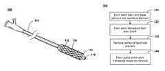
- FIG. 1is an illustration of a system for treating a vascular condition including a stent coupled to a catheter, in accordance with one embodiment of the current invention
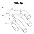
- FIG. 2Ais a cross-sectional perspective view of a stent framework, in accordance with one embodiment of the current invention.
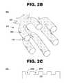
- FIG. 2Bis a cross-sectional perspective view of a stent framework, in accordance with one embodiment of the current invention.
- FIG. 2Cis a cross-sectional perspective view of a stent framework, in accordance with one embodiment of the current invention.
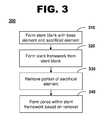
- FIG. 3is a flow diagram of a method of manufacturing a stent, in accordance with one embodiment of the current invention.
- FIG. 4is a flow diagram of a method of manufacturing a vascular treatment system, in accordance with one embodiment of the current invention.
- FIG. 5is a flow diagram of a method treating a vascular condition, in accordance with one aspect of the invention.
- FIG. 1shows an illustration of a system for treating a vascular condition, comprising a stent coupled to a catheter, in accordance with one embodiment of the present invention at 100 .
- Stent with catheter 100includes a stent 120 coupled to a delivery catheter 110 .
- Stent 120includes a stent framework 130 .
- at least one drug coating, or a drug-polymer layeris applied to a surface of the stent framework.
- Insertion of stent 120 into a vessel in the bodyhelps treat, for example, heart disease, various cardiovascular ailments, and other vascular conditions.
- Catheter-deployed stent 120typically is used to treat one or more blockages, occlusions, stenoses, or diseased regions in the coronary artery, femoral artery, peripheral arteries, and other arteries in the body.
- Treatment of vascular conditionsmay include the prevention or correction of various ailments and deficiencies associated with the cardiovascular system, the cerebrovascular system, urinogenital systems, biliary conduits, abdominal passageways and other biological vessels within the body.
- the stent frameworkcomprises an alloy comprising base elements and sacrificial elements and other substances.
- the sacrificial elementis an element to be leached or dealloyed prior to insertion into a body lumen.
- Catheter 110 of an exemplary embodiment of the present inventionincludes a balloon 112 that expands and deploys the stent within a vessel of the body. After positioning stent 120 within the vessel with the assistance of a guide wire traversing through a guide wire lumen 114 inside catheter 110 , balloon 112 is inflated by pressurizing a fluid such as a contrast fluid or saline solution that fills a tube inside catheter 110 and balloon 112 . Stent 120 is expanded until a desired diameter is reached, and then the contrast fluid is depressurized or pumped out, separating balloon 112 from stent 120 and leaving the stent 120 deployed in the vessel of the body. Alternately, catheter 110 may include a sheath that retracts to allow expansion of a self-expanding version of stent 120 .
- a fluidsuch as a contrast fluid or saline solution that fills a tube inside catheter 110 and balloon 112 .
- Stent 120is expanded until a desired diameter is reached, and then the contrast fluid is de
- FIG. 2Ashows a cross-sectional perspective view of a stent, in accordance with one embodiment of the present invention at 200 .
- a stent 220includes a stent framework 230 .
- FIG. 2Aillustrates the stent prior to leaching of a sacrificial element from the stent framework.
- Stent framework 230comprises a metallic base formed of constituent elements, such as cobalt-chromium, stainless steel, nitinol, magnesium, tantalum, MP35N alloy, platinum, titanium, a chromium-based alloy, a suitable biocompatible alloy, a suitable biocompatible material, a biocompatible polymer, or a combination thereof.
- the alloydoes not include yttrium, neodymium, or zirconium. Either prior to attachment to a catheter, or after attachment to a catheter, a dealloying process is applied to the stent framework to remove at least a portion of the sacrificial elements from the stent framework.
- a pore or nanoporeis left in the space previously occupied by the leached sacrificial element. Tissue ingrowth into the pores may improve biocompatibility, and the volume of space defined by the pores can increase the drug carrying capacity of the stent.
- the distribution of the formed porescan be controlled into a desired pattern in one embodiment.
- the formed porescan assume a particular pattern, such as sinusoid, quincunx, or other.
- the formed porescan be dispersed on only a single side of the stent, such as the side of the stent opposite a lumen formed by the stent framework.
- the distribution of the formed poresis uncontrolled.
- the stent frameworkcan be further coated with additional layers of material, such as therapeutic agents, cap coats, polymeric layers, or the like.
- a drug coatingis disposed on stent framework 230 .
- the drug coatingincludes at least one drug layer.
- at least one coating layeris disposed over the stent framework, and can envelop the drug coating layer.
- the drug layerincludes at least a first therapeutic agent.
- coating layersinclude magnesium, or another bioabsorbable constituent.
- the coating layersare sputter coats.
- the magnesium coatingis applied using another appropriate technique, such as vacuum deposition, dipping, or the like.
- the coating layeris a topcoat.
- multiple sets of drug and coating layersmay be disposed on stent framework 230 .
- ten sets of layers, each layer on the order of 0.1 micrometers thickcan be alternately disposed on stent framework 230 to produce a two-micrometer thick coating.
- twenty sets of layers, each layer on the order of 0.5 micrometers thickcan be alternately disposed on stent framework 230 to produce a twenty-micrometer thick coating.
- the drug layers and the coating layersneed not be the same thickness, and the thickness of each may be varied throughout the drug coating.
- at least one drug layeris applied to an outer surface of the stent framework.
- the drug layercan comprise a first therapeutic agent such as camptothecin, rapamycin, a rapamycin derivative, or a rapamycin analog.
- at least one coating layercomprises a magnesium layer of a predetermined thickness.
- the thickness of the magnesium coatingis selected based on expected leaching rates, while in other embodiments, the thickness is selected based on the drug maintained in place between the stent framework surface and the magnesium layer.
- the thickness of the magnesium layeris variable over the length of the stent framework.
- Drug or magnesium elutionrefers to the transfer of a therapeutic agent from the drug coating to the surrounding area or bloodstream in a body. The amount of drug eluted is determined as the total amount of therapeutic agent excreted out of the drug coating, typically measured in units of weight such as micrograms, or in weight per peripheral area of the stent.
- FIG. 2Billustrates the stent 200 of FIG. 2A after leaching of the magnesium from the stent framework results in a plurality of pores 222 within the surface of the stent.
- FIGS. 2A and 2Billustrate the stent framework as substantially tubular in cross-section.
- FIG. 2Cillustrates a stent framework 201 cross-section using a single strut of the framework with a substantially planar construction.
- Stent 201includes a framework after the sacrificial element/s has leached from magnesium-alloyed portion 298 , including a plurality of pores 299 .
- Other geometric strut configurationsare also anticipated, as well as variable configurations.
- FIG. 3illustrates one embodiment of a method 300 for manufacturing a stent with nanopores, in accordance with one aspect of the invention.
- Method 300begins by forming a stent blank including a predetermined alloy composition, the alloy composition including at least base element and at least one sacrificial element, at block 310 .
- the base elementincludes a metallic element selected for certain physical characteristics, such as machinability, strength, or the like.
- the base elementcan be stainless steel, cobalt, chromium, MP35N, nitinol, tantalum, or the like.
- the sacrificial elementis an element selected to be leached from the combined alloy to form a plurality of pores throughout the stent framework.
- the sacrificial elementcan be magnesium, phosphorus, copper, boron, silicon, zinc, carbon, or the like.
- the base element and sacrificial elementare noble metals, and the sacrificial element is a lesser noble metal than the base element.
- the sacrificial elementis selected responsive to physical characteristics, such as melting point, machining considerations, or the like.
- the stent blankis formed from a molten alloy comprising the base element and sacrificial element. In one embodiment, the stent blank is an ingot.
- the base elementcan be a ceramic or graphite, and the sacrificial element is driven into the base element in bulk after formation of the stent blank of the base element.
- the solidification processis controlled to increase control of pore orientation during a dealloying process.
- the cooling temperatureis controlled to form a cone and skin, for example.
- the temperatureis controlled to increase formation of inter-dendritic regions on a surface of the cooled alloy.
- the temperature gradientis controlled to affect the solidification rate as well as growth of columnar or cored structures grown epitaxially on the surface of the matrix.
- the epitaxially grown structuresare then subject to additional surface modification, such as etching or mechanical modifications to produce inter-dendritic regions includes a network of spaces, such as pores, to be filled with a therapeutic agent and/or polymer.
- a cooled ingotcan be subjected to incipient melting to secure surface material characteristics in accord with a desired porosity characteristic.
- a material with a lower melt phasecan precipitate out at the surface while largely preserving structural integrity of the final product.
- a sacrificial elementis introduced into the ingot by coating and driving sacrificial elements into the bulk ingot or stent blank.
- the alloyis subjected to a constitutional supercooling, resulting in a solute rich layer generated at the interface between alloy constituents.
- a rapid quench during solidificationincreases formation of cellular structures and affects the breakdown of the planar interface near a grain boundary.
- the cooling processis controlled to affect the formation of plates formed between dendrite arms in the solidified grain structure. These plates can be controlled to result in abrupt concentration changes between the dendrite center and interdendritic regions, increasing the concentration of the sacrificial element within the interdendritic regions.
- certain embodiments of the inventionfurther adjust quenching rates to affect the dendrite arm spacing.
- the alloy grainsare controlled to reduce formation of dendritic arms, creating a nondendritic alloy.
- Such alloyshave increased segregation of alloy constituents in an equiaxed region.
- the alloy constituentsinclude a zirconium-refined magnesium alloy.
- a stent frameworkis formed from the stent blank at step 320 .
- the stent frameworkis formed with any appropriate machining technique, including cutting, stamping or the like. Depending on the shape of the stent to be manufactured, the stent framework can be cut from the blank, or bent into the desired shape. Other machining techniques are also appropriate, depending on the shape and alloyed material.
- the sacrificial elementis removed from the stent framework, at step 330 .
- the sacrificial elementis removed via a dealloying process.
- the dealloying processis determined based on the base element and sacrificial element.
- the dealloying processincludes application of inductive heat to the stent framework.
- the dealloying processcomprises application of at least one chemical reagent to the stent framework.
- the dealloying processcomprises application of at least one electrical field to the stent framework.
- the dealloying processcomprises application of heat to the stent framework.
- the dealloying processcomprises use of a laser. In another embodiment, the dealloying process includes use of an electron beam. In one embodiment, a mask is applied to predetermined areas of the stent framework to shield at least a portion of the stent framework from the dealloying process. For example, the crown of a stent can be masked to prevent formation of pores within the crown, an area of the stent subject to higher mechanical stress and strain than other areas. In addition, the sacrificial element can be removed throughout the entire thickness of the stent framework, or only a selected depth.
- the formation techniquesincluding the cooling of the alloy, improve the ability to dealloy the sacrificial element, such as by increasing the concentration of the sacrificial element in the interdendritic spaces of the alloy, or by increasing the interdendritic space.
- At least one poreis formed, at step 340 .
- the volume of space previously occupied by the sacrificial elementbecomes a pore.
- the methodfurther includes applying at least one therapeutic agent to the stent, including the pores.
- the poresreceive tissue ingrowth. In embodiments without the application of the therapeutic agent, the pores may still receive tissue ingrowth.
- a stentis manufactured in accordance with method 300 such that steps 410 , 420 , 430 , and 440 are implemented in a similar fashion as step 310 , 320 , 330 , and 340 .
- the manufactured stentis bent into a delivery shape, and then disposed, step 450 , on a catheter.
- the method for treating vascular conditionincludes manufacturing a stent in accordance with method 300 such that steps 510 , 520 , 530 , and 540 are implemented in a similar fashion as step 310 , 320 , 330 , and 340 .
- the bent manufactured stentis bent into a delivery shape and disposed, step 550 , on a catheter and delivered, step 560 , to a treatment site via the catheter.
- the delivered stentis then deployed, and tissue ingrowth is received in the pores in step 570 .
- the methodfurther includes applying at least one therapeutic agent to the manufactured stent, either before or after bending, and either before or after applying the stent to the catheter, but prior to delivery to the treatment site.
- the therapeutic agentis then eluted from the stent.
- the term ‘therapeutic agent’includes a number of pharmaceutical drugs that have the potential to be used in drug, or drug-polymer coatings.
- an antirestenotic agentsuch as rapamycin prevents or reduces the recurrence of narrowing and blockage of the bodily vessel.
- An antisense drugworks at the genetic level to interrupt the process by which disease-causing proteins are produced.
- An antineoplastic agentis typically used to prevent, kill, or block the growth and spread of cancer cells in the vicinity of the stent.
- An antiproliferative agentmay prevent or stop targeted cells or cell types from growing.
- An antithrombogenic agentactively retards blood clot formation.
- An anticoagulantoften delays or prevents blood coagulation with anticoagulant therapy, using compounds such as heparin and coumarins.
- An antiplatelet agentmay be used to act upon blood platelets, inhibiting their function in blood coagulation.
- An antibioticis frequently employed to kill or inhibit the growth of microorganisms and to combat disease and infection.
- An anti-inflammatory agentsuch as dexamethasone can be used to counteract or reduce inflammation in the vicinity of the stent. At times, a steroid is used to reduce scar tissue in proximity to an implanted stent.
- a gene therapy agentmay be capable of changing the expression of a person's genes to treat, cure or ultimately prevent disease.
- a bioactive agentis any therapeutic substance that provides treatment of disease or disorders.
- An organic drugis any small-molecule therapeutic material.
- a pharmaceutical compoundis any compound that provides a therapeutic effect.
- a recombinant DNA product or a recombinant RNA productincludes altered DNA or RNA genetic material.
- Bioactive agents of pharmaceutical valuemay also include collagen and other proteins, saccharides, and their derivatives. The molecular weight of the bioactive agent typically ranges from about 200 to 60,000 Dalton and above.
Landscapes
- Health & Medical Sciences (AREA)
- Heart & Thoracic Surgery (AREA)
- Veterinary Medicine (AREA)
- Public Health (AREA)
- General Health & Medical Sciences (AREA)
- Animal Behavior & Ethology (AREA)
- Life Sciences & Earth Sciences (AREA)
- Vascular Medicine (AREA)
- Chemical & Material Sciences (AREA)
- Epidemiology (AREA)
- Surgery (AREA)
- Engineering & Computer Science (AREA)
- Biomedical Technology (AREA)
- Cardiology (AREA)
- Optics & Photonics (AREA)
- Physics & Mathematics (AREA)
- Dispersion Chemistry (AREA)
- Oral & Maxillofacial Surgery (AREA)
- Transplantation (AREA)
- Inorganic Chemistry (AREA)
- Materials For Medical Uses (AREA)
- Prostheses (AREA)
Abstract
Description
Claims (34)
Priority Applications (3)
| Application Number | Priority Date | Filing Date | Title |
|---|---|---|---|
| US11/778,430US8205317B2 (en) | 2007-07-16 | 2007-07-16 | Method of manufacturing a controlled porosity stent |
| EP08772524.8AEP2178473B1 (en) | 2007-07-16 | 2008-07-11 | Controlled alloy stent |
| PCT/US2008/069784WO2009012146A1 (en) | 2007-07-16 | 2008-07-11 | Controlled alloy stent |
Applications Claiming Priority (1)
| Application Number | Priority Date | Filing Date | Title |
|---|---|---|---|
| US11/778,430US8205317B2 (en) | 2007-07-16 | 2007-07-16 | Method of manufacturing a controlled porosity stent |
Publications (2)
| Publication Number | Publication Date |
|---|---|
| US20090024199A1 US20090024199A1 (en) | 2009-01-22 |
| US8205317B2true US8205317B2 (en) | 2012-06-26 |
Family
ID=39718965
Family Applications (1)
| Application Number | Title | Priority Date | Filing Date |
|---|---|---|---|
| US11/778,430Expired - Fee RelatedUS8205317B2 (en) | 2007-07-16 | 2007-07-16 | Method of manufacturing a controlled porosity stent |
Country Status (3)
| Country | Link |
|---|---|
| US (1) | US8205317B2 (en) |
| EP (1) | EP2178473B1 (en) |
| WO (1) | WO2009012146A1 (en) |
Families Citing this family (28)
| Publication number | Priority date | Publication date | Assignee | Title |
|---|---|---|---|---|
| WO2003002243A2 (en) | 2001-06-27 | 2003-01-09 | Remon Medical Technologies Ltd. | Method and device for electrochemical formation of therapeutic species in vivo |
| US20090093875A1 (en)* | 2007-05-01 | 2009-04-09 | Abbott Laboratories | Drug eluting stents with prolonged local elution profiles with high local concentrations and low systemic concentrations |
| US7758892B1 (en)* | 2004-05-20 | 2010-07-20 | Boston Scientific Scimed, Inc. | Medical devices having multiple layers |
| US8840660B2 (en)* | 2006-01-05 | 2014-09-23 | Boston Scientific Scimed, Inc. | Bioerodible endoprostheses and methods of making the same |
| US8089029B2 (en) | 2006-02-01 | 2012-01-03 | Boston Scientific Scimed, Inc. | Bioabsorbable metal medical device and method of manufacture |
| US20070224244A1 (en)* | 2006-03-22 | 2007-09-27 | Jan Weber | Corrosion resistant coatings for biodegradable metallic implants |
| US8048150B2 (en)* | 2006-04-12 | 2011-11-01 | Boston Scientific Scimed, Inc. | Endoprosthesis having a fiber meshwork disposed thereon |
| EP2054537A2 (en) | 2006-08-02 | 2009-05-06 | Boston Scientific Scimed, Inc. | Endoprosthesis with three-dimensional disintegration control |
| ES2357661T3 (en) | 2006-09-15 | 2011-04-28 | Boston Scientific Scimed, Inc. | BIOEROSIONABLE ENDOPROOTHESIS WITH BIOESTABLE INORGANIC LAYERS. |
| EP2959925B1 (en)* | 2006-09-15 | 2018-08-29 | Boston Scientific Limited | Medical devices and methods of making the same |
| JP2010503489A (en)* | 2006-09-15 | 2010-02-04 | ボストン サイエンティフィック リミテッド | Biodegradable endoprosthesis and method for producing the same |
| WO2008034066A1 (en) | 2006-09-15 | 2008-03-20 | Boston Scientific Limited | Bioerodible endoprostheses and methods of making the same |
| EP2073764A2 (en)* | 2006-09-18 | 2009-07-01 | Boston Scientific Limited | Controlling biodegradation of a medical instrument |
| WO2008036548A2 (en)* | 2006-09-18 | 2008-03-27 | Boston Scientific Limited | Endoprostheses |
| ES2506144T3 (en)* | 2006-12-28 | 2014-10-13 | Boston Scientific Limited | Bioerodible endoprosthesis and their manufacturing procedure |
| US8052745B2 (en)* | 2007-09-13 | 2011-11-08 | Boston Scientific Scimed, Inc. | Endoprosthesis |
| US8118857B2 (en)* | 2007-11-29 | 2012-02-21 | Boston Scientific Corporation | Medical articles that stimulate endothelial cell migration |
| US20090143855A1 (en)* | 2007-11-29 | 2009-06-04 | Boston Scientific Scimed, Inc. | Medical Device Including Drug-Loaded Fibers |
| WO2009079389A2 (en)* | 2007-12-14 | 2009-06-25 | Boston Scientific Limited | Drug-eluting endoprosthesis |
| US7998192B2 (en)* | 2008-05-09 | 2011-08-16 | Boston Scientific Scimed, Inc. | Endoprostheses |
| US20090287301A1 (en)* | 2008-05-16 | 2009-11-19 | Boston Scientific, Scimed Inc. | Coating for medical implants |
| US8236046B2 (en) | 2008-06-10 | 2012-08-07 | Boston Scientific Scimed, Inc. | Bioerodible endoprosthesis |
| US20100004733A1 (en)* | 2008-07-02 | 2010-01-07 | Boston Scientific Scimed, Inc. | Implants Including Fractal Structures |
| US7985252B2 (en)* | 2008-07-30 | 2011-07-26 | Boston Scientific Scimed, Inc. | Bioerodible endoprosthesis |
| US8382824B2 (en)* | 2008-10-03 | 2013-02-26 | Boston Scientific Scimed, Inc. | Medical implant having NANO-crystal grains with barrier layers of metal nitrides or fluorides |
| EP2403546A2 (en)* | 2009-03-02 | 2012-01-11 | Boston Scientific Scimed, Inc. | Self-buffering medical implants |
| US20110022158A1 (en)* | 2009-07-22 | 2011-01-27 | Boston Scientific Scimed, Inc. | Bioerodible Medical Implants |
| US8668732B2 (en)* | 2010-03-23 | 2014-03-11 | Boston Scientific Scimed, Inc. | Surface treated bioerodible metal endoprostheses |
Citations (32)
| Publication number | Priority date | Publication date | Assignee | Title |
|---|---|---|---|---|
| US6013854A (en)* | 1994-06-17 | 2000-01-11 | Terumo Kabushiki Kaisha | Indwelling stent and the method for manufacturing the same |
| US6253443B1 (en)* | 1997-09-30 | 2001-07-03 | Scimed Life Systems, Inc. | Method of forming a stent |
| US6325821B1 (en)* | 1997-04-29 | 2001-12-04 | Sorin Biomedica Cardio S.P.A. | Stent for angioplasty |
| US20020019660A1 (en) | 1998-09-05 | 2002-02-14 | Marc Gianotti | Methods and apparatus for a curved stent |
| US20040040416A1 (en)* | 2002-08-27 | 2004-03-04 | Jonah Erlebacher | Method of forming nanoporous membranes |
| WO2004043292A2 (en)* | 2002-11-13 | 2004-05-27 | Setagon, Inc. | Medical devices having porous layers and methods for making same |
| US20040237282A1 (en)* | 2003-06-02 | 2004-12-02 | Hines Richard A. | Process for forming a porous drug delivery layer |
| US20040247642A1 (en)* | 2001-07-18 | 2004-12-09 | Cedars-Sinai Medical Center | Instrument coated with magnesium-based compound for reducing thrombosis |
| US20050060021A1 (en) | 2003-09-16 | 2005-03-17 | O'brien Barry | Medical devices |
| US20050070990A1 (en)* | 2003-09-26 | 2005-03-31 | Stinson Jonathan S. | Medical devices and methods of making same |
| US20050070989A1 (en)* | 2002-11-13 | 2005-03-31 | Whye-Kei Lye | Medical devices having porous layers and methods for making the same |
| US20050096733A1 (en) | 2001-12-29 | 2005-05-05 | Kovneristy July K. | Stent and method for the production thereof (variants) |
| US20050251245A1 (en)* | 2004-05-05 | 2005-11-10 | Karl Sieradzki | Methods and apparatus with porous materials |
| WO2006020742A2 (en) | 2004-08-13 | 2006-02-23 | Setagon, Inc. | Medical devices having nanoporous layers and methods for making the same |
| US20060121080A1 (en)* | 2002-11-13 | 2006-06-08 | Lye Whye K | Medical devices having nanoporous layers and methods for making the same |
| GB2425485A (en) | 2005-04-29 | 2006-11-01 | Veryan Medical Ltd | Shape memory stent producing non planar, swirling flow |
| US20070131318A1 (en)* | 2005-12-12 | 2007-06-14 | Accellent, Inc. | Medical alloys with a non-alloyed dispersion and methods of making same |
| US20070224099A1 (en)* | 2006-03-27 | 2007-09-27 | Juergen Biener | Gold-containing catalyst with porous structure |
| US20070296103A1 (en)* | 2006-06-27 | 2007-12-27 | The Regents Of The University Of California | Filter casting nanoscale porous materials |
| US20080086198A1 (en)* | 2002-11-13 | 2008-04-10 | Gary Owens | Nanoporous stents with enhanced cellular adhesion and reduced neointimal formation |
| US20080097591A1 (en)* | 2006-10-20 | 2008-04-24 | Biosensors International Group | Drug-delivery endovascular stent and method of use |
| US20080189928A1 (en)* | 2007-02-12 | 2008-08-14 | Medtronic Vascular, Inc. | Stent Ring Surface Formation |
| US20080249599A1 (en)* | 2007-04-05 | 2008-10-09 | Medtronic Vascular, Inc. | Stent With Therapeutic Agent Delivery Structures in Low Strain Regions |
| US20090118823A1 (en)* | 2007-11-02 | 2009-05-07 | Boston Scientific Scimed, Inc. | Endoprosthesis with porous reservoir |
| US7550005B2 (en)* | 1995-06-07 | 2009-06-23 | Cook Incorporated | Coated implantable medical device |
| US20090192592A1 (en)* | 2007-02-13 | 2009-07-30 | Cinvention Ag | Porous implant structure |
| US20090196899A1 (en)* | 2008-01-31 | 2009-08-06 | Medtronic Vascular, Inc. | Controlled Alloy Stent |
| US7575593B2 (en)* | 2007-01-30 | 2009-08-18 | Medtronic Vascular, Inc. | Implantable device with reservoirs for increased drug loading |
| US20090228089A1 (en)* | 2008-03-04 | 2009-09-10 | Medtronic Vascular, Inc. | Full Thickness Porous Stent |
| US20090292352A1 (en)* | 2002-06-27 | 2009-11-26 | Boston Scientific Scimed, Inc. | Methods of making medical devices |
| US7647687B2 (en)* | 2005-09-14 | 2010-01-19 | Boston Scientific Scimed, Inc. | Method of manufacturing a stent |
| US7682388B2 (en)* | 2007-01-30 | 2010-03-23 | Medtronic Vascular, Inc. | Stent with longitudinal groove |
- 2007
- 2007-07-16USUS11/778,430patent/US8205317B2/ennot_activeExpired - Fee Related
- 2008
- 2008-07-11EPEP08772524.8Apatent/EP2178473B1/enactiveActive
- 2008-07-11WOPCT/US2008/069784patent/WO2009012146A1/enactiveApplication Filing
Patent Citations (46)
| Publication number | Priority date | Publication date | Assignee | Title |
|---|---|---|---|---|
| US6013854A (en)* | 1994-06-17 | 2000-01-11 | Terumo Kabushiki Kaisha | Indwelling stent and the method for manufacturing the same |
| US7550005B2 (en)* | 1995-06-07 | 2009-06-23 | Cook Incorporated | Coated implantable medical device |
| US6325821B1 (en)* | 1997-04-29 | 2001-12-04 | Sorin Biomedica Cardio S.P.A. | Stent for angioplasty |
| US6253443B1 (en)* | 1997-09-30 | 2001-07-03 | Scimed Life Systems, Inc. | Method of forming a stent |
| US20010029660A1 (en)* | 1997-09-30 | 2001-10-18 | Johnson Michael W. | Stent drug delivery system |
| US20020019660A1 (en) | 1998-09-05 | 2002-02-14 | Marc Gianotti | Methods and apparatus for a curved stent |
| US20040247642A1 (en)* | 2001-07-18 | 2004-12-09 | Cedars-Sinai Medical Center | Instrument coated with magnesium-based compound for reducing thrombosis |
| US20050096733A1 (en) | 2001-12-29 | 2005-05-05 | Kovneristy July K. | Stent and method for the production thereof (variants) |
| US20090292352A1 (en)* | 2002-06-27 | 2009-11-26 | Boston Scientific Scimed, Inc. | Methods of making medical devices |
| US20040040416A1 (en)* | 2002-08-27 | 2004-03-04 | Jonah Erlebacher | Method of forming nanoporous membranes |
| US6805972B2 (en)* | 2002-08-27 | 2004-10-19 | Johns Hopkins University | Method of forming nanoporous membranes |
| US20080086198A1 (en)* | 2002-11-13 | 2008-04-10 | Gary Owens | Nanoporous stents with enhanced cellular adhesion and reduced neointimal formation |
| US20060276884A1 (en)* | 2002-11-13 | 2006-12-07 | Whye-Kei Lye | Nanoporous stents with magnesium leaching |
| US20050070989A1 (en)* | 2002-11-13 | 2005-03-31 | Whye-Kei Lye | Medical devices having porous layers and methods for making the same |
| WO2004043292A2 (en)* | 2002-11-13 | 2004-05-27 | Setagon, Inc. | Medical devices having porous layers and methods for making same |
| US20040148015A1 (en)* | 2002-11-13 | 2004-07-29 | Setagon, Inc. | Medical devices having porous layers and methods for making same |
| US7294409B2 (en)* | 2002-11-13 | 2007-11-13 | University Of Virgina | Medical devices having porous layers and methods for making same |
| US20060121080A1 (en)* | 2002-11-13 | 2006-06-08 | Lye Whye K | Medical devices having nanoporous layers and methods for making the same |
| US20060193890A1 (en)* | 2002-11-13 | 2006-08-31 | Owens Gary K | Method for loading nanoporous layers with therapeutic agent |
| US20060193887A1 (en)* | 2002-11-13 | 2006-08-31 | Owens Gary K | Medical devices having nanoporous bonding layers |
| US20060193886A1 (en)* | 2002-11-13 | 2006-08-31 | Owens Gary K | Medical devices with nanoporous layers and topcoats |
| US20060193888A1 (en)* | 2002-11-13 | 2006-08-31 | Whye-Kei Lye | Methods for using medical devices having nanoporous layers |
| US20060193889A1 (en)* | 2002-11-13 | 2006-08-31 | Joshua Spradlin | Nanoporous layers using thermal dealloying |
| US20060276877A1 (en)* | 2002-11-13 | 2006-12-07 | Gary Owens | Dealloyed nanoporous stents |
| US20060276885A1 (en)* | 2002-11-13 | 2006-12-07 | Whye-Kei Lye | Nanoporous stents with improved radiolucency |
| US20060276879A1 (en)* | 2002-11-13 | 2006-12-07 | Whye-Kei Lye | Medical devices having porous layers and methods for making the same |
| US20060276878A1 (en)* | 2002-11-13 | 2006-12-07 | Gary Owens | Dealloyed nanoporous stents |
| US20040237282A1 (en)* | 2003-06-02 | 2004-12-02 | Hines Richard A. | Process for forming a porous drug delivery layer |
| US20050060021A1 (en) | 2003-09-16 | 2005-03-17 | O'brien Barry | Medical devices |
| US20050070990A1 (en)* | 2003-09-26 | 2005-03-31 | Stinson Jonathan S. | Medical devices and methods of making same |
| US20050251245A1 (en)* | 2004-05-05 | 2005-11-10 | Karl Sieradzki | Methods and apparatus with porous materials |
| WO2006020742A2 (en) | 2004-08-13 | 2006-02-23 | Setagon, Inc. | Medical devices having nanoporous layers and methods for making the same |
| GB2425485A (en) | 2005-04-29 | 2006-11-01 | Veryan Medical Ltd | Shape memory stent producing non planar, swirling flow |
| US7647687B2 (en)* | 2005-09-14 | 2010-01-19 | Boston Scientific Scimed, Inc. | Method of manufacturing a stent |
| US20070131318A1 (en)* | 2005-12-12 | 2007-06-14 | Accellent, Inc. | Medical alloys with a non-alloyed dispersion and methods of making same |
| US20070224099A1 (en)* | 2006-03-27 | 2007-09-27 | Juergen Biener | Gold-containing catalyst with porous structure |
| US20070296103A1 (en)* | 2006-06-27 | 2007-12-27 | The Regents Of The University Of California | Filter casting nanoscale porous materials |
| US20080097591A1 (en)* | 2006-10-20 | 2008-04-24 | Biosensors International Group | Drug-delivery endovascular stent and method of use |
| US7682388B2 (en)* | 2007-01-30 | 2010-03-23 | Medtronic Vascular, Inc. | Stent with longitudinal groove |
| US7575593B2 (en)* | 2007-01-30 | 2009-08-18 | Medtronic Vascular, Inc. | Implantable device with reservoirs for increased drug loading |
| US20080189928A1 (en)* | 2007-02-12 | 2008-08-14 | Medtronic Vascular, Inc. | Stent Ring Surface Formation |
| US20090192592A1 (en)* | 2007-02-13 | 2009-07-30 | Cinvention Ag | Porous implant structure |
| US20080249599A1 (en)* | 2007-04-05 | 2008-10-09 | Medtronic Vascular, Inc. | Stent With Therapeutic Agent Delivery Structures in Low Strain Regions |
| US20090118823A1 (en)* | 2007-11-02 | 2009-05-07 | Boston Scientific Scimed, Inc. | Endoprosthesis with porous reservoir |
| US20090196899A1 (en)* | 2008-01-31 | 2009-08-06 | Medtronic Vascular, Inc. | Controlled Alloy Stent |
| US20090228089A1 (en)* | 2008-03-04 | 2009-09-10 | Medtronic Vascular, Inc. | Full Thickness Porous Stent |
Non-Patent Citations (2)
| Title |
|---|
| Flemings, Merton "Solidification Processing" pp. 58-176. |
| Rostoker, William et al. "Interpretation of Metallographic Structures" pp. 105-107. |
Also Published As
| Publication number | Publication date |
|---|---|
| EP2178473A1 (en) | 2010-04-28 |
| EP2178473B1 (en) | 2015-09-02 |
| US20090024199A1 (en) | 2009-01-22 |
| WO2009012146A1 (en) | 2009-01-22 |
Similar Documents
| Publication | Publication Date | Title |
|---|---|---|
| US8205317B2 (en) | Method of manufacturing a controlled porosity stent | |
| US20090196899A1 (en) | Controlled Alloy Stent | |
| US20080243234A1 (en) | Magnesium Alloy Stent | |
| EP1866006B1 (en) | Medical devices including composites | |
| US6725901B1 (en) | Methods of manufacture of fully consolidated or porous medical devices | |
| US8956403B2 (en) | Medical implant including a magnesium-based tie layer | |
| EP2134383B1 (en) | Drug coated stent with magnesium topcoat | |
| US10589005B2 (en) | Bioerodible magnesium alloy microstructures for endoprostheses | |
| EP1688155A1 (en) | Cell growth-inhibiting film, medical instrument and stent for digestive organs | |
| US20020138136A1 (en) | Medical device having radio-opacification and barrier layers | |
| JP2008500886A (en) | Medical device of permeable metal material for bioactive substance delivery | |
| JP2006500996A (en) | Apparatus and method for delivering mitomycin via an eluting biocompatible implantable medical device | |
| CA2583252A1 (en) | Medical devices and methods of making the same | |
| EP2175900A2 (en) | Endoprostheses containing boride intemetallic phases | |
| US20200061251A1 (en) | Iron-based biodegradable metals for implantable medical devices | |
| EP2170422A2 (en) | Molybdenum endoprostheses | |
| WO2004064910A1 (en) | Indwelling stent | |
| US7682388B2 (en) | Stent with longitudinal groove | |
| JP2001190688A (en) | Stent | |
| US8303639B2 (en) | Releasable polymer on drug elution stent and method | |
| US7972375B2 (en) | Endoprostheses including metal matrix composite structures | |
| EP1839626A1 (en) | Medical devices having porous layers and methods for making same |
Legal Events
| Date | Code | Title | Description |
|---|---|---|---|
| AS | Assignment | Owner name:MEDTRONIC VASCULAR, INC., CALIFORNIA Free format text:ASSIGNMENT OF ASSIGNORS INTEREST;ASSIGNORS:BIRDSALL, MATTHEW J.;ALLEN, JEFFREY W.;REEL/FRAME:019561/0833;SIGNING DATES FROM 20070615 TO 20070716 Owner name:MEDTRONIC VASCULAR, INC., CALIFORNIA Free format text:ASSIGNMENT OF ASSIGNORS INTEREST;ASSIGNORS:BIRDSALL, MATTHEW J.;ALLEN, JEFFREY W.;SIGNING DATES FROM 20070615 TO 20070716;REEL/FRAME:019561/0833 | |
| ZAAA | Notice of allowance and fees due | Free format text:ORIGINAL CODE: NOA | |
| ZAAB | Notice of allowance mailed | Free format text:ORIGINAL CODE: MN/=. | |
| STCF | Information on status: patent grant | Free format text:PATENTED CASE | |
| FPAY | Fee payment | Year of fee payment:4 | |
| MAFP | Maintenance fee payment | Free format text:PAYMENT OF MAINTENANCE FEE, 8TH YEAR, LARGE ENTITY (ORIGINAL EVENT CODE: M1552); ENTITY STATUS OF PATENT OWNER: LARGE ENTITY Year of fee payment:8 | |
| FEPP | Fee payment procedure | Free format text:MAINTENANCE FEE REMINDER MAILED (ORIGINAL EVENT CODE: REM.); ENTITY STATUS OF PATENT OWNER: LARGE ENTITY | |
| LAPS | Lapse for failure to pay maintenance fees | Free format text:PATENT EXPIRED FOR FAILURE TO PAY MAINTENANCE FEES (ORIGINAL EVENT CODE: EXP.); ENTITY STATUS OF PATENT OWNER: LARGE ENTITY | |
| STCH | Information on status: patent discontinuation | Free format text:PATENT EXPIRED DUE TO NONPAYMENT OF MAINTENANCE FEES UNDER 37 CFR 1.362 | |
| FP | Lapsed due to failure to pay maintenance fee | Effective date:20240626 |