US8205181B1 - Victim net crosstalk reduction - Google Patents
Victim net crosstalk reductionDownload PDFInfo
- Publication number
- US8205181B1 US8205181B1US12/718,624US71862410AUS8205181B1US 8205181 B1US8205181 B1US 8205181B1US 71862410 AUS71862410 AUS 71862410AUS 8205181 B1US8205181 B1US 8205181B1
- Authority
- US
- United States
- Prior art keywords
- circuit
- delay
- range
- net
- delay range
- Prior art date
- Legal status (The legal status is an assumption and is not a legal conclusion. Google has not performed a legal analysis and makes no representation as to the accuracy of the status listed.)
- Expired - Fee Related, expires
Links
Images


Classifications
- G—PHYSICS
- G06—COMPUTING OR CALCULATING; COUNTING
- G06F—ELECTRIC DIGITAL DATA PROCESSING
- G06F30/00—Computer-aided design [CAD]
- G06F30/30—Circuit design
- G06F30/39—Circuit design at the physical level
- G06F30/398—Design verification or optimisation, e.g. using design rule check [DRC], layout versus schematics [LVS] or finite element methods [FEM]
- G—PHYSICS
- G06—COMPUTING OR CALCULATING; COUNTING
- G06F—ELECTRIC DIGITAL DATA PROCESSING
- G06F30/00—Computer-aided design [CAD]
- G06F30/30—Circuit design
- G06F30/32—Circuit design at the digital level
- G06F30/33—Design verification, e.g. functional simulation or model checking
- G06F30/3308—Design verification, e.g. functional simulation or model checking using simulation
- G06F30/3312—Timing analysis
- G—PHYSICS
- G06—COMPUTING OR CALCULATING; COUNTING
- G06F—ELECTRIC DIGITAL DATA PROCESSING
- G06F2119/00—Details relating to the type or aim of the analysis or the optimisation
- G06F2119/10—Noise analysis or noise optimisation
- G—PHYSICS
- G06—COMPUTING OR CALCULATING; COUNTING
- G06F—ELECTRIC DIGITAL DATA PROCESSING
- G06F2119/00—Details relating to the type or aim of the analysis or the optimisation
- G06F2119/12—Timing analysis or timing optimisation
Definitions
- This inventiongenerally relates to signal networking and, more particularly, to a system and method for minimizing the susceptibility of a signal network to aggressor net timing window overlap.
- a hold time violationmay occur, when an input signal changes too quickly after the clock's active transition.
- a setup time violationmay occur when a signal arrives too late, and misses the time when it should advance.
- the time when a signal arrivescan vary due to many reasons—the input data may vary, the circuit may perform different operations, the temperature and voltage may change, and there are manufacturing differences in the exact construction of each part.
- Static Timing Analysisis used to develop early and late arrival times (timing window) for each relevant net or node. This timing window is enlarged by a worst case assessment of crosstalk noise for both early and late arrival times using noise aware STA. This worst case timing window is used for timing analysis of all paths through the corresponding net and a list of paths that fail timing requirements are provided.
- STAStatic Timing Analysis
- the word staticalludes to the fact that this timing analysis is carried out in an input-independent manner, and purports to find the worst-case delay of the circuit over all possible input combinations.
- STAis a method of computing the expected timing of a digital circuit without performing a simulation.
- High-performance ICshave conventionally been characterized by the clock frequency at which they operate. Gauging the operation of a circuit at a specified speed requires an ability to measure, during the design process, its delay at numerous steps. Moreover, delay calculations must be incorporated into the inner loop of timing optimizers at various phases of design, such as logic synthesis, layout (placement and routing), and in in-place optimizations performed late in the design cycle. While such timing measurements can theoretically be performed using a rigorous circuit simulation, such an approach is liable to be too slow to be practical. Static timing analysis plays a vital role in facilitating the fast and reasonably accurate measurement of circuit timing.
- the critical pathis defined as the path between an input and an output with the maximum delay.
- the arrival time of a signalis the time elapsed for a signal to arrive at a certain point.
- the reference, or time 0.0is often taken as the arrival time of a clock signal.
- delay calculation of all the components in the pathis required. Arrival times, and indeed almost all times in timing analysis, are normally kept as a pair of values—the earliest possible time at which a signal can change, and the latest.
- Required timeis the latest time at which a signal can arrive without making the clock cycle longer than desired.
- the computation of the required timeproceeds as follows. At each primary output, the required times for rise/fall are set according to the specifications provided to the circuit. Next, a backward topological traversal is carried out, processing each gate when the required times at all of its fanouts are known.
- the slack associated with each connectionis the difference between the required time and the arrival time.
- a positive slack (s) at a nodeimplies that the arrival time at that node may be increased by (s) without affecting the overall delay of the circuit. Conversely, negative slack implies that a path is too slow, and the path must be sped up (or the reference signal delayed) if the whole circuit is to work at the desired speed.
- the behavior of an electronic circuitis often dependent on various factors in its environment like temperature or local voltage variations. In such a case either STA needs to be performed for more than one such set of conditions, or STA must be prepared to work with a range of possible delays for each component, as opposed to a single value. If the design works at each extreme condition, then under the assumption of monotonic behavior, the design is also qualified for all intermediate points.
- FIG. 1is a schematic diagram illustrating a timing window associated with a simple logic gate (prior art).
- a timing windowis the time during which a net can toggle its logical value.
- TWtiming window
- the input “a” of the AND gateis changing at 3 ns and the input “b” is changing at 4.5 ns. So the timing window for the output “x” of this AND gate is 3 ns-4.5 ns, which means this net can toggle at any time in this time intervals, depending upon factors such as the process voltage temperature (PVT).
- PVTprocess voltage temperature
- FIGS. 2A and 2Bare, respectively, a schematic diagram of a network of victim and aggressor nets, and an associated timing diagram (prior art).
- the aggressor netsare shown connected to the victim net via parasitic capacitors.
- the parasitic capacitorsare not necessarily circuit components, but represent an AC coupling between nets.
- the victim netis the AND gate of FIG. 1 with a timing window of 3 to 4.5 ns.
- the term “timing window”is understood be the range of signal delay through a net, and the terms “timing window” and “delay range” are used interchangeable.
- a first aggressor nethas an output coupled to the victim net, and has a timing window of 2 to 3.5 ns.
- a second aggressor nethas an output coupled to the victim net, and has a timing window of 4 to 5 ns.
- An “aggressor”is defined as any net that causes a coupled switching net to either slow or hasten its timing window. Alternately, an aggressor net may cause a coupled switching net to incorrectly change its logical value output. A victim net is a switching net being impacted by an aggressor net.
- the crosstalk effect between any 2 netsdepends upon following factors: 1) the coupling capacitance between the aggressor and victim nets; 2) how fast the aggressor and/or the victim nets are switching; and, 3) the timing window overlap of the aggressor and victim nets.
- the first two factorsare addressed by physically increasing the spacing between aggressor and victim nets, thereby reducing the capacitive coupling, and by upsizing/downsizing the driver of aggressor/victim net to change the transition times of the nets.
- the problem with the above techniquesis that they directly involve changing the cells/nets in the timing critical path, which may change the normal timing (timing without crosstalk) of the critical path, and lead to an iterative design process.
- there has been little discussion in the artaddressing the third factor—of minimizing the timing window overlap.
- timing window overlapcould be shrunk without affecting the timing critical path of either the victim or aggressor net.
- Described hereinare a system and design method for reducing the crosstalk noise of coupled nets by addressing the physical design of a system-on-chip (SoC), without relocating or modifying the actual components of the affected nets.
- SoCsystem-on-chip
- the simultaneous switching of the aggressor and victim netsis avoided by changing the timing windows of the nets, while maintaining the timing critical path specifications.
- the physical layouts of the affected netsare not modified, so that the original static timing analysis (STA) remains valid, thus avoiding analysis iterations.
- STAstatic timing analysis
- a circuit analysis toolis provided, enabled with software instructions, for minimizing circuit crosstalk.
- the instructionsprovide a first circuit connected to an output mode, having a last gate with a plurality of inputs and an output.
- the instructionscalculate a first circuit victim net delay range (timing window) having a minimum delay (Vmin) and a maximum delay (Vmax).
- a second circuitis provided having an output connected to the output node to supply an aggressor net delay range (A 1 ) having a minimum delay (A 1 min ) and a maximum delay (A 1 max ).
- the aggressor net delay rangeat least partially overlaps the victim net delay range. Without increasing the value of Vmax (critical path timing), the first circuit victim net delay range is shrunk, thereby minimizing crosstalk between the first and second circuits without an increase in first circuit maximum signal delay.
- the first circuit victim net delay rangeis calculated by deriving a range of signal delays (Imin and Imax) for each last gate input (j).
- the range of signal delays for the gate outputis calculated in response to comparing the gate delay range for each input (j), deriving the smallest Imin value and the largest Imax value.
- the victim net delay rangeis shrunk by, for each input (j), finding the difference between the largest Imax value and the I j max value for that input.
- a circuit delayis added prior to each gate input, equal to the difference.
- FIG. 1is a schematic diagram illustrating a timing window associated with a simple logic gate (prior art).
- FIGS. 2A and 2Bare, respectively, a schematic diagram of a network of victim and aggressor nets, and an associated timing diagram (prior art).
- FIG. 3is a schematic block diagram of a system of hardware devices connected with minimal signal crosstalk.
- FIG. 4is a timing diagram associated with the system of FIG. 3 .
- FIG. 5is a timing diagram illustrating a scenario where the victim net is shrunk without completely eliminating overlap with the aggressor net.
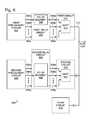
- FIG. 6is a schematic block diagram depicting a first variation of the system of FIG. 3 .
- FIG. 7is a timing diagram associated with the system depicted in FIG. 6 .
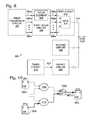
- FIG. 8is a schematic block diagram depicting a second variation of the system of FIG. 3 .
- FIG. 9is a timing diagram associated with the system of FIG. 8 .
- FIG. 10is schematic diagram depicting an exemplary circuit candidate for victim net timing window shrinkage.
- FIG. 11is the schematic diagram of FIG. 10 , where the “clouds” have been replaced with logic gates.
- FIG. 12is a flowchart supporting a method for shrinking a victim net timing window.
- FIG. 13is a schematic diagram of the system of FIG. 11 , after the addition of the delays calculated using the method of FIG. 12 .
- FIG. 14is a schematic block diagram with the addition of a delay element that prevents overlap between the victim net and aggressor net n2.
- FIG. 15is a timing diagram depicting the overlap between a victim net timing window and a plurality of aggressor net timing windows.
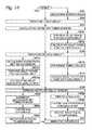
- FIG. 16is a flowchart illustrating a circuit analysis tool, enabled with software instructions stored in a computer-readable medium and executed by a processor, for minimizing circuit crosstalk.
- FIG. 17is a flowchart illustrating a variation of the circuit analysis tool of FIG. 16 , for minimizing circuit crosstalk exposure.
- FIG. 3is a schematic block diagram of a system of hardware devices connected with minimal signal crosstalk.
- the system 300comprises a first preliminary circuit 302 having a first plurality of outputs 304 whose combination results in a preliminary net delay range (P) with a minimum delay (Pmin) and a maximum delay (Pmax), where (d 1 +P) at least partially overlaps aggressor net delay range (A 1 ). Shown are outputs 304 a through 304 n , where n is a variable not limited to any particular value.
- a first delay circuit 306has a first plurality of inputs 304 connected to the first preliminary circuit outputs, a first plurality of outputs 306 ( 306 a through 306 n ).
- a first circuit 310has a gate 314 with the delay d 1 , a first plurality of inputs connected to the first delay circuit outputs 306 , and an output connected to an output node on line 312 .
- the first circuit 310has a victim net delay range with a minimum delay (Vmin) and a maximum delay (Vmax).
- a second circuit 316has an output connected to the output node on line 312 to supply the aggressor net delay range (A 1 ) having a minimum delay (A 1 min ) and a maximum delay (A 1 max ). Ideally, the aggressor net delay range fails to overlap the victim net delay range, and Vmin>A 1 max.
- FIG. 4is a timing diagram associated with the system of FIG. 3 .
- the victim net delay rangewould be (Pmin+d 1 ) to (Pmax+d 1 ), which is the first preliminary circuit net delay range (P) plus the delay through the first circuit 310 .
- This delay rangewould overlap the aggressor net delay range (A 1 ), which would result in crosstalk between the first circuit 310 and the second circuit 316 .
- the addition of the first delay circuitchanges the value of Vmin, without affecting the critical delay path Vmax, and prevents the victim net from overlapping the aggressor net (A 1 ).
- the first preliminary circuit 302has a range of signal delays (Omin and Omax) for each output 306 , and the first preliminary circuit delay range is found by contrasting the smallest (minimum delay) Omin value and the largest (maximum delay) Omax value.
- the first delay circuit 306includes delay element 308 connected to each input 306 , with a delay equal to the difference between the largest Omax value and the Omax value for that input.
- each output 306has a discrete delay value, as opposed to a range of values.
- output 306 ahas the smallest Omin value of Pmin
- outputs 306 b and 306 nboth have delays equal to (Pmin+d 1 ), which is the largest Omax value.
- the addition of delay (d), associated with delay element 308shrinks the victim net from (Pmin+d 1 ) to Vmin ((Pmin+d 1 +d)), and prevents net overlap.
- FIG. 5is a timing diagram illustrating a scenario where the victim net is shrunk without completely eliminating overlap with the aggressor net.
- the victim net“fits inside” the aggressor net, so that it is impossible to shrink the victim net to prevent overlap (without increasing the value of Vmax).
- the victim netcan be shrunk, as shown, to at least minimize the overlap between the two nets.
- FIG. 6is a schematic block diagram depicting a first variation of the system of FIG. 3 .
- both the victim net and the aggressor net A 1are shrunk to prevent overlap with a third circuit net A 2 .
- a second preliminary circuit 600has a second plurality of outputs 602 whose combination results in a preliminary net delay range (S) with a minimum delay (5 min) and a maximum delay (Smax). (d 2 +S) at least partially overlaps the victim net delay range (Vmin to Vmax). Shown are outputs 602 a through 602 p , where p is a variable not limited to any particular value.
- a second delay circuit 604has a second plurality of inputs connected to the second preliminary circuit outputs 602 , a second plurality of outputs 606 a to 606 p , and at least one delay element 608 .
- Delay element 608has a delay (Sd), and interposed between an input 602 and an output 606 :
- the second circuit 316has a gate 610 with the delay d 2 , a second plurality of inputs connected to the second delay circuit outputs 606 a through 606 p , an output connected to the output node on line 312 .
- the second circuit 316has an aggressor net delay range with the minimum delay (A 1 min ) greater than Vmax.
- the second preliminary circuit 600has a range of signal delays (Omin and Omax) for each output 602 , and the second preliminary circuit delay range is found by contrasting the smallest Omin value and the largest Omax value.
- the second delay circuit 604includes a delay element 608 connected to each input 602 with a delay equal to the difference between the largest Omax value and the Omax value for that input.
- Each input 602may have a range of delays (Ojmin to Ojmax).
- a third circuit 612having an aggressor net delay range (A 2 ), characterized with a timing window A 2 min -A 2 max , which partially overlaps the victim net.
- FIG. 7is a timing diagram associated with the system depicted in FIG. 6 . Without the influence of the first delay circuit 306 , the victim net would overlap aggressor net delay range (A 2 ). As in the example of FIGS. 3 and 4 , the victim net timing window is shrunk by increasing the delay associated with Vmin. In the interest of brevity, the details of shrinking the victim window are not repeated here.
- each output 602has a discrete delay value, as opposed to a range of values.
- Output 602 bmay have the smallest Omin value of 5 min, while outputs 306 a and 306 p both have delay equal to (Smin+d 2 ), which is the largest Omax value.
- the addition of delay (Sd), associated with delay element 608shrinks the aggressor net from (Smin+d 2 ) to Vmin ((Pmin+d 1 +d)), and prevents net overlap.
- FIG. 8is a schematic block diagram depicting a second variation of the system of FIG. 3 .
- the third circuit 612has an output on line 802 to supply a third circuit net delay range (Z), characterized by timing window Zmin-Zmax, at least partially overlapping the aggressor net delay range (A 1 ) and the victim net delay range.
- An offset circuit 800has an input connected to the third circuit output on line 802 and an output connected to the output node on line 312 , to supply an aggressor net delay range (A 2 ), which is the third circuit net delay range (Z: Zmin-Zmax) delayed by the value d 3 .
- the aggressor net delay range (A 2 )fails to overlap the aggressor net delay range (A 1 ).
- the aggressor net delay range (A 1 )is a victim net in context to the third circuit net delay range (Z).
- nets A 1 and A 2do not overlap. However, the maximum delay of the third circuit net has been increased.
- FIG. 9is a timing diagram associated with the system of FIG. 8 .
- the victim netis shrunk to eliminate the overlap between the victim net (Vmin-Vmax) and the aggressor net (A 1 ).
- the victim netcannot be shrunk to eliminate overlap with third circuit net Z (Zmin-Zmax).
- the crosstalk with the victim netcan be minimizing by offsetting third circuit net delay range (Z), to eliminate the overlap between net (Z) and aggressor net (A 1 ).
- FIG. 10is schematic diagram depicting an exemplary circuit candidate for victim net timing window shrinkage.
- the path from flop FF 1 ( 1004 ) to flop FF 3is bit relaxed and is not timing critical, as there is sufficient setup margin available.
- the net from the AND gate 1006 output to flop FF 3 input (net v1)is the victim net under consideration for crosstalk reduction.
- the “clouds” 1008 and 1010represent circuit elements that will be added in subsequent figures.
- FIG. 11is the schematic diagram of FIG. 10 , where the “clouds” have been replaced with logic gates.
- the victim net (net v1)is exposed to two aggressor nets: n1 ( 1004 ) and n2 ( 1006 ), coupled to the victim net via capacitors 1100 and 1102 , respectively.
- Table 1shows the timing window for each node in the system.
- FIG. 12is a flowchart supporting a method for shrinking a victim net timing window.
- a user-defined value for the marginis defined as 250 picoseconds (ps)
- the setup slack in the highlighted timing pathsis ⁇ 200 (ps)
- the crosstalk delta delay on the victim net v1is also 200 ps.
- Step 1202a determination is made if slack ⁇ 0. If not, the method exits in Step 1204 .
- FIG. 13is a schematic diagram of the system of FIG. 11 , after the addition of the delays calculated using the method of FIG. 12 .
- Delay element 1300with a delay of 0.6 ns, is interposed between output node x1 and input node a3. With the addition of delay element 1300 , the timing window of node a3 has shifted by 600 ps and, thus, the timing window of victim net v1 has shrunk from 3 ns:6 ns to 3.6 ns:6 ns. Since aggressor net n1 and victim net v1 timing windows no longer overlap, net n1 is no longer an aggressor for v1.
- FIG. 14is a schematic block diagram with the addition of a delay element that prevents overlap between the victim net and aggressor net n2.
- FIG. 15is a timing diagram depicting the overlap between a victim net timing window and a plurality of aggressor net timing windows. As described above in the explanation of FIGS. 8 and 9 , if it is not possible to shrink the timing windows of aggressor/victim nets further, an offset technique can be used to ensure that the simultaneous switching of all the aggressor nets can be avoided by rearranging the timing windows of the aggressor nets.
- FIG. 16is a flowchart illustrating a circuit analysis tool, enabled with software instructions stored in a computer-readable medium and executed by a processor, for minimizing circuit crosstalk.
- the use of computers to read and execute instructions from memoryis well known in the art, and the instructions are not limited to any particular protocol or computer hardware.
- a componentmay be, but is not limited to being, a process running on a processor, a processor, an object, an executable, a thread of execution, a program, and/or a computer.
- an application running on a computing device and the computing devicecan be a component.
- One or more componentscan reside within a process and/or thread of execution and a component may be localized on one computer and/or distributed between two or more computers.
- these componentscan execute from various computer readable media having various data structures stored thereon.
- the componentsmay communicate by way of local and/or remote processes such as in accordance with a signal having one or more data packets (e.g., data from one component interacting with another component in a local system, distributed system, and/or across a network such as the Internet with other systems by way of the signal).
- Non-volatile mediaincludes, for example, optical or magnetic disks.
- Volatile mediaincludes dynamic memory.
- Computer-readable mediainclude, for example, a floppy disk, a flexible disk, hard disk, magnetic tape, or any other magnetic medium, a CD-ROM, any other optical medium, punch cards, paper tape, any other physical medium with patterns of holes, a RAM, a PROM, and EPROM, a FLASH-EPROM, any other memory chip or cartridge, a carrier wave as described hereinafter, or any other medium from which a computer can read.
- Step 1602provides a first circuit connected to an output mode, having a last gate with a plurality of inputs and an output.
- Step 1604calculates a first circuit victim net delay range having a minimum delay (Vmin) and a maximum delay (Vmax).
- Step 1606provides a second circuit having an output connected to the output node to supply an aggressor net delay range (A 1 ) having a minimum delay (A 1 min ) and a maximum delay (A 1 max ).
- the aggressor net delay rangeat least partially overlaps the victim net delay range.
- Step 1608shrinks the first circuit victim net delay range.
- Step 1610minimizes crosstalk between the first and second circuits without an increase in first circuit maximum signal delay. If shrinking the first circuit victim net delay range in Step 1608 includes eliminating the overlap between the victim net delay range and aggressor net delay range, then Step 1610 eliminates crosstalk between the first and second circuits.
- calculating the first circuit victim net delay range in Step 1604includes substeps.
- Step 1604 aderives a range of signal delays (Imin and Imax) for each last gate input (j).
- Step 1604 bcalculates the range of signal delays for the gate output.
- Shrinking the victim net delay range in Step 1608includes the following substeps. For each input (j), Step 1608 b finds the difference between the largest Imax value and the I j max value for that input.
- Step 1608 cadds a circuit delay prior to each gate input, equal to the difference.
- Step 1601selects a margin value. Then, shrinking the victim net delay range in Step 1608 includes additional substeps. Step 1608 a finds the difference between Vmax and Vmin, and Step 1608 c adds the circuit delays prior to each gate input if the difference is greater than the margin value.
- Step 1606provides a second circuit with a last gate having a plurality of inputs and an output.
- Step 1607 acalculates the second circuit aggressor net (A 1 ) delay range with the following substeps.
- Step 1607 a 1derives a range of signal delays (Imin and Imax) for each last gate input (j).
- Step 1607 a 2calculates the range of signal delays for the gate output.
- Step 1609shrinks the second circuit aggressor net delay range (A 1 ) without increasing the value of A 1 max , with the following substeps. For each input (j), Step 1609 a finds the difference between the largest Imax value and the I j max value for that input. Step 1609 b adds a circuit delay prior to each gate input, equal to the difference.
- Step 1607 bprovides a third circuit having the output connected to the output node to supply an aggressor net delay range (A 2 ) at least partially overlapping the victim net delay range and the aggressor net delay range (A 1 ).
- Step 1612adds a delay to either the second or third circuit, such that A 1 does not overlap A 2 .
- Step 1612may be performed in parallel with Step 1609 , which shrinks the second circuit net delay range (A 1 ), the third circuit net delay range (A 2 ), or both A 1 and A 2 .
- Step 1607 bprovides a third circuit, and Step 1609 may shrinks the second circuit net delay range (A 1 ), the third circuit net delay range (A 2 ), or both A 1 and A 2 , without the performance of Step 1612 .
- FIG. 17is a flowchart illustrating a variation of the circuit analysis tool of FIG. 16 , for minimizing circuit crosstalk exposure.
- the instructionsbegin at Step 1700 .
- Step 1702provides a first circuit connected to an output mode, having a last gate with a plurality of inputs and an output.
- Step 1704provides a second circuit having an output connected to the output node to supply an aggressor net delay range (A 1 ) having a minimum delay (A 1 min ) and a maximum delay (A 1 max ), where the aggressor net delay range at least partially overlaps the victim net delay range.
- a 1aggressor net delay range having a minimum delay (A 1 min ) and a maximum delay (A 1 max )
- Step 1706provides a third circuit having the output connected to the output node to supply an aggressor net delay range (A 2 ) at least partially overlapping the victim net delay range and the aggressor net delay range (A 1 ).
- Step 1708calculates a first circuit victim net delay range having a minimum delay (Vmin) and a maximum delay (Vmax).
- Step 1710adds a delay to either the second or third circuit, such that A 1 does not overlap A 2 .
- Step 1712minimizes crosstalk between the first circuit, and the second and third circuits, without an increase in the first circuit maximum signal delay.
Landscapes
- Engineering & Computer Science (AREA)
- Computer Hardware Design (AREA)
- Physics & Mathematics (AREA)
- Theoretical Computer Science (AREA)
- Evolutionary Computation (AREA)
- Geometry (AREA)
- General Engineering & Computer Science (AREA)
- General Physics & Mathematics (AREA)
- Design And Manufacture Of Integrated Circuits (AREA)
Abstract
Description
| TABLE 1 | |||||
| Node/net | Timing Window (min:max ) | ||||
| 3 | ns:3.4 ns | |||||
| b1 | 5.1 | ns:5.4 ns | ||||
| 3 | ns:5.4 ns | |||||
| a2 | 4.8 | ns:5.4 ns | ||||
| b2 | 5.5 | ns:6 ns | ||||
| x2 | 4.8 | ns:6 ns | ||||
| a3 = | 3 | ns:5.4 ns | ||||
| b3 = x2 | 4.8 | ns:6 ns | ||||
| x3/ | 3 | ns:6 ns | ||||
| 3 | ns:3.6 ns | |||||
| n2 | 4 | ns:5 ns | ||||
Claims (10)
Priority Applications (1)
| Application Number | Priority Date | Filing Date | Title |
|---|---|---|---|
| US12/718,624US8205181B1 (en) | 2010-03-05 | 2010-03-05 | Victim net crosstalk reduction |
Applications Claiming Priority (1)
| Application Number | Priority Date | Filing Date | Title |
|---|---|---|---|
| US12/718,624US8205181B1 (en) | 2010-03-05 | 2010-03-05 | Victim net crosstalk reduction |
Publications (1)
| Publication Number | Publication Date |
|---|---|
| US8205181B1true US8205181B1 (en) | 2012-06-19 |
Family
ID=46209651
Family Applications (1)
| Application Number | Title | Priority Date | Filing Date |
|---|---|---|---|
| US12/718,624Expired - Fee RelatedUS8205181B1 (en) | 2010-03-05 | 2010-03-05 | Victim net crosstalk reduction |
Country Status (1)
| Country | Link |
|---|---|
| US (1) | US8205181B1 (en) |
Cited By (95)
| Publication number | Priority date | Publication date | Assignee | Title |
|---|---|---|---|---|
| US20120137263A1 (en)* | 2010-11-29 | 2012-05-31 | International Business Machines Corporation | Timing closure in chip design |
| US20130080987A1 (en)* | 2010-07-09 | 2013-03-28 | Michael Howard Kipper | Method and apparatus for simultaneous switching noise optimization |
| US8543954B1 (en)* | 2007-08-31 | 2013-09-24 | Cadence Design Systems, Inc. | Concurrent noise and delay modeling of circuit stages for static timing analysis of integrated circuit designs |
| CN103338007A (en)* | 2013-06-04 | 2013-10-02 | 上海华力创通半导体有限公司 | A noise processing method and a circuit after a noise processing process |
| US8595669B1 (en)* | 2007-08-31 | 2013-11-26 | Cadence Design Systems, Inc. | Flexible noise and delay modeling of circuit stages for static timing analysis of integrated circuit designs |
| US9015644B2 (en) | 2012-08-06 | 2015-04-21 | Wistron Corp. | Crosstalk analysis method |
| US9032349B2 (en) | 2012-08-06 | 2015-05-12 | Wistron Corp. | Crosstalk analysis method |
| US9053267B2 (en)* | 2011-12-22 | 2015-06-09 | Intel Corporation | Noise analysis using timing models |
| US20160274759A1 (en) | 2008-08-25 | 2016-09-22 | Paul J. Dawes | Security system with networked touchscreen and gateway |
| US10051078B2 (en) | 2007-06-12 | 2018-08-14 | Icontrol Networks, Inc. | WiFi-to-serial encapsulation in systems |
| US10062245B2 (en) | 2005-03-16 | 2018-08-28 | Icontrol Networks, Inc. | Cross-client sensor user interface in an integrated security network |
| US10062273B2 (en) | 2010-09-28 | 2018-08-28 | Icontrol Networks, Inc. | Integrated security system with parallel processing architecture |
| US10078958B2 (en) | 2010-12-17 | 2018-09-18 | Icontrol Networks, Inc. | Method and system for logging security event data |
| US10079839B1 (en) | 2007-06-12 | 2018-09-18 | Icontrol Networks, Inc. | Activation of gateway device |
| US10091014B2 (en) | 2005-03-16 | 2018-10-02 | Icontrol Networks, Inc. | Integrated security network with security alarm signaling system |
| US10127801B2 (en) | 2005-03-16 | 2018-11-13 | Icontrol Networks, Inc. | Integrated security system with parallel processing architecture |
| US10142394B2 (en) | 2007-06-12 | 2018-11-27 | Icontrol Networks, Inc. | Generating risk profile using data of home monitoring and security system |
| US10142392B2 (en) | 2007-01-24 | 2018-11-27 | Icontrol Networks, Inc. | Methods and systems for improved system performance |
| US10140840B2 (en) | 2007-04-23 | 2018-11-27 | Icontrol Networks, Inc. | Method and system for providing alternate network access |
| US10142166B2 (en) | 2004-03-16 | 2018-11-27 | Icontrol Networks, Inc. | Takeover of security network |
| US10156831B2 (en) | 2004-03-16 | 2018-12-18 | Icontrol Networks, Inc. | Automation system with mobile interface |
| US10200504B2 (en) | 2007-06-12 | 2019-02-05 | Icontrol Networks, Inc. | Communication protocols over internet protocol (IP) networks |
| US10237806B2 (en) | 2009-04-30 | 2019-03-19 | Icontrol Networks, Inc. | Activation of a home automation controller |
| US10237237B2 (en) | 2007-06-12 | 2019-03-19 | Icontrol Networks, Inc. | Communication protocols in integrated systems |
| US10242149B2 (en) | 2014-12-17 | 2019-03-26 | International Business Machines Corporation | Enhancing integrated circuit noise performance |
| US10313303B2 (en) | 2007-06-12 | 2019-06-04 | Icontrol Networks, Inc. | Forming a security network including integrated security system components and network devices |
| US10339791B2 (en) | 2007-06-12 | 2019-07-02 | Icontrol Networks, Inc. | Security network integrated with premise security system |
| US10348575B2 (en) | 2013-06-27 | 2019-07-09 | Icontrol Networks, Inc. | Control system user interface |
| US10365810B2 (en) | 2007-06-12 | 2019-07-30 | Icontrol Networks, Inc. | Control system user interface |
| US10382452B1 (en) | 2007-06-12 | 2019-08-13 | Icontrol Networks, Inc. | Communication protocols in integrated systems |
| US10380871B2 (en) | 2005-03-16 | 2019-08-13 | Icontrol Networks, Inc. | Control system user interface |
| US10389736B2 (en) | 2007-06-12 | 2019-08-20 | Icontrol Networks, Inc. | Communication protocols in integrated systems |
| US10423309B2 (en) | 2007-06-12 | 2019-09-24 | Icontrol Networks, Inc. | Device integration framework |
| US10498830B2 (en) | 2007-06-12 | 2019-12-03 | Icontrol Networks, Inc. | Wi-Fi-to-serial encapsulation in systems |
| US10523689B2 (en) | 2007-06-12 | 2019-12-31 | Icontrol Networks, Inc. | Communication protocols over internet protocol (IP) networks |
| US10522026B2 (en) | 2008-08-11 | 2019-12-31 | Icontrol Networks, Inc. | Automation system user interface with three-dimensional display |
| US10530839B2 (en) | 2008-08-11 | 2020-01-07 | Icontrol Networks, Inc. | Integrated cloud system with lightweight gateway for premises automation |
| US10559193B2 (en) | 2002-02-01 | 2020-02-11 | Comcast Cable Communications, Llc | Premises management systems |
| US10616075B2 (en) | 2007-06-12 | 2020-04-07 | Icontrol Networks, Inc. | Communication protocols in integrated systems |
| US10666523B2 (en) | 2007-06-12 | 2020-05-26 | Icontrol Networks, Inc. | Communication protocols in integrated systems |
| US10691295B2 (en) | 2004-03-16 | 2020-06-23 | Icontrol Networks, Inc. | User interface in a premises network |
| US10721087B2 (en) | 2005-03-16 | 2020-07-21 | Icontrol Networks, Inc. | Method for networked touchscreen with integrated interfaces |
| US10747216B2 (en) | 2007-02-28 | 2020-08-18 | Icontrol Networks, Inc. | Method and system for communicating with and controlling an alarm system from a remote server |
| US10785319B2 (en) | 2006-06-12 | 2020-09-22 | Icontrol Networks, Inc. | IP device discovery systems and methods |
| US10841381B2 (en) | 2005-03-16 | 2020-11-17 | Icontrol Networks, Inc. | Security system with networked touchscreen |
| US10979389B2 (en) | 2004-03-16 | 2021-04-13 | Icontrol Networks, Inc. | Premises management configuration and control |
| US10999254B2 (en) | 2005-03-16 | 2021-05-04 | Icontrol Networks, Inc. | System for data routing in networks |
| US11089122B2 (en) | 2007-06-12 | 2021-08-10 | Icontrol Networks, Inc. | Controlling data routing among networks |
| US11113950B2 (en) | 2005-03-16 | 2021-09-07 | Icontrol Networks, Inc. | Gateway integrated with premises security system |
| US11146637B2 (en) | 2014-03-03 | 2021-10-12 | Icontrol Networks, Inc. | Media content management |
| US11153266B2 (en) | 2004-03-16 | 2021-10-19 | Icontrol Networks, Inc. | Gateway registry methods and systems |
| US11182060B2 (en) | 2004-03-16 | 2021-11-23 | Icontrol Networks, Inc. | Networked touchscreen with integrated interfaces |
| US11201755B2 (en) | 2004-03-16 | 2021-12-14 | Icontrol Networks, Inc. | Premises system management using status signal |
| US11212192B2 (en) | 2007-06-12 | 2021-12-28 | Icontrol Networks, Inc. | Communication protocols in integrated systems |
| US11218878B2 (en) | 2007-06-12 | 2022-01-04 | Icontrol Networks, Inc. | Communication protocols in integrated systems |
| US11237714B2 (en) | 2007-06-12 | 2022-02-01 | Control Networks, Inc. | Control system user interface |
| US11240059B2 (en) | 2010-12-20 | 2022-02-01 | Icontrol Networks, Inc. | Defining and implementing sensor triggered response rules |
| US11244545B2 (en) | 2004-03-16 | 2022-02-08 | Icontrol Networks, Inc. | Cross-client sensor user interface in an integrated security network |
| US11258625B2 (en) | 2008-08-11 | 2022-02-22 | Icontrol Networks, Inc. | Mobile premises automation platform |
| US11277465B2 (en) | 2004-03-16 | 2022-03-15 | Icontrol Networks, Inc. | Generating risk profile using data of home monitoring and security system |
| US11310199B2 (en) | 2004-03-16 | 2022-04-19 | Icontrol Networks, Inc. | Premises management configuration and control |
| US11316958B2 (en) | 2008-08-11 | 2022-04-26 | Icontrol Networks, Inc. | Virtual device systems and methods |
| US11316753B2 (en) | 2007-06-12 | 2022-04-26 | Icontrol Networks, Inc. | Communication protocols in integrated systems |
| US11343380B2 (en) | 2004-03-16 | 2022-05-24 | Icontrol Networks, Inc. | Premises system automation |
| US11368327B2 (en) | 2008-08-11 | 2022-06-21 | Icontrol Networks, Inc. | Integrated cloud system for premises automation |
| US11398147B2 (en) | 2010-09-28 | 2022-07-26 | Icontrol Networks, Inc. | Method, system and apparatus for automated reporting of account and sensor zone information to a central station |
| US11405463B2 (en) | 2014-03-03 | 2022-08-02 | Icontrol Networks, Inc. | Media content management |
| US11424980B2 (en) | 2005-03-16 | 2022-08-23 | Icontrol Networks, Inc. | Forming a security network including integrated security system components |
| US11423756B2 (en) | 2007-06-12 | 2022-08-23 | Icontrol Networks, Inc. | Communication protocols in integrated systems |
| US11451409B2 (en) | 2005-03-16 | 2022-09-20 | Icontrol Networks, Inc. | Security network integrating security system and network devices |
| US11489812B2 (en) | 2004-03-16 | 2022-11-01 | Icontrol Networks, Inc. | Forming a security network including integrated security system components and network devices |
| US11496568B2 (en) | 2005-03-16 | 2022-11-08 | Icontrol Networks, Inc. | Security system with networked touchscreen |
| US11582065B2 (en) | 2007-06-12 | 2023-02-14 | Icontrol Networks, Inc. | Systems and methods for device communication |
| US11601810B2 (en) | 2007-06-12 | 2023-03-07 | Icontrol Networks, Inc. | Communication protocols in integrated systems |
| US11615697B2 (en) | 2005-03-16 | 2023-03-28 | Icontrol Networks, Inc. | Premise management systems and methods |
| US11646907B2 (en) | 2007-06-12 | 2023-05-09 | Icontrol Networks, Inc. | Communication protocols in integrated systems |
| US11677577B2 (en) | 2004-03-16 | 2023-06-13 | Icontrol Networks, Inc. | Premises system management using status signal |
| US11700142B2 (en) | 2005-03-16 | 2023-07-11 | Icontrol Networks, Inc. | Security network integrating security system and network devices |
| US11706279B2 (en) | 2007-01-24 | 2023-07-18 | Icontrol Networks, Inc. | Methods and systems for data communication |
| US11706045B2 (en) | 2005-03-16 | 2023-07-18 | Icontrol Networks, Inc. | Modular electronic display platform |
| US11729255B2 (en) | 2008-08-11 | 2023-08-15 | Icontrol Networks, Inc. | Integrated cloud system with lightweight gateway for premises automation |
| US11750414B2 (en) | 2010-12-16 | 2023-09-05 | Icontrol Networks, Inc. | Bidirectional security sensor communication for a premises security system |
| US11758026B2 (en) | 2008-08-11 | 2023-09-12 | Icontrol Networks, Inc. | Virtual device systems and methods |
| US11792036B2 (en) | 2008-08-11 | 2023-10-17 | Icontrol Networks, Inc. | Mobile premises automation platform |
| US11792330B2 (en) | 2005-03-16 | 2023-10-17 | Icontrol Networks, Inc. | Communication and automation in a premises management system |
| US11811845B2 (en) | 2004-03-16 | 2023-11-07 | Icontrol Networks, Inc. | Communication protocols over internet protocol (IP) networks |
| US11816323B2 (en) | 2008-06-25 | 2023-11-14 | Icontrol Networks, Inc. | Automation system user interface |
| US11831462B2 (en) | 2007-08-24 | 2023-11-28 | Icontrol Networks, Inc. | Controlling data routing in premises management systems |
| US11916928B2 (en) | 2008-01-24 | 2024-02-27 | Icontrol Networks, Inc. | Communication protocols over internet protocol (IP) networks |
| US11916870B2 (en) | 2004-03-16 | 2024-02-27 | Icontrol Networks, Inc. | Gateway registry methods and systems |
| US12003387B2 (en) | 2012-06-27 | 2024-06-04 | Comcast Cable Communications, Llc | Control system user interface |
| US12063221B2 (en) | 2006-06-12 | 2024-08-13 | Icontrol Networks, Inc. | Activation of gateway device |
| US12063220B2 (en) | 2004-03-16 | 2024-08-13 | Icontrol Networks, Inc. | Communication protocols in integrated systems |
| US12184443B2 (en) | 2007-06-12 | 2024-12-31 | Icontrol Networks, Inc. | Controlling data routing among networks |
| US12283172B2 (en) | 2007-06-12 | 2025-04-22 | Icontrol Networks, Inc. | Communication protocols in integrated systems |
Citations (11)
| Publication number | Priority date | Publication date | Assignee | Title |
|---|---|---|---|---|
| US6499131B1 (en)* | 1999-07-15 | 2002-12-24 | Texas Instruments Incorporated | Method for verification of crosstalk noise in a CMOS design |
| US6637014B2 (en)* | 2001-03-06 | 2003-10-21 | Nec Corporation | Crosstalk mitigation method and system |
| US20040015338A1 (en)* | 2002-07-19 | 2004-01-22 | Lawrence William Richard | Method and apparatus for automated signal integrity checking |
| US6988255B2 (en)* | 2001-10-09 | 2006-01-17 | International Business Machines Corporation | Generation of refined switching windows in static timing analysis |
| US20060112359A1 (en)* | 2004-11-22 | 2006-05-25 | Becer Murat R | Pessimism reduction in crosstalk noise aware static timing analysis |
| US20070226673A1 (en)* | 2006-03-27 | 2007-09-27 | Habitz Peter A | Method of reducing correclated coupling between nets |
| US7359843B1 (en)* | 2003-09-19 | 2008-04-15 | Cadence Design Systems, Inc. | Robust calculation of crosstalk delay change in integrated circuit design |
| US7383522B2 (en)* | 2004-10-08 | 2008-06-03 | Fujitsu Limited | Crosstalk-aware timing analysis |
| US7519932B2 (en)* | 2005-04-07 | 2009-04-14 | Kabushiki Kaisha Toshiba | System and method for analyzing crosstalk occurring in a semiconductor integrated circuit |
| US20100083202A1 (en)* | 2008-09-30 | 2010-04-01 | Sachin Shrivastava | Method and system for performing improved timing window analysis |
| US20100218152A1 (en)* | 2009-02-23 | 2010-08-26 | Peivand Tehrani | Variation aware victim and aggressor timing overlap detection by pessimism reduction based on relative positions of timing windows |
- 2010
- 2010-03-05USUS12/718,624patent/US8205181B1/ennot_activeExpired - Fee Related
Patent Citations (12)
| Publication number | Priority date | Publication date | Assignee | Title |
|---|---|---|---|---|
| US6499131B1 (en)* | 1999-07-15 | 2002-12-24 | Texas Instruments Incorporated | Method for verification of crosstalk noise in a CMOS design |
| US6637014B2 (en)* | 2001-03-06 | 2003-10-21 | Nec Corporation | Crosstalk mitigation method and system |
| US6988255B2 (en)* | 2001-10-09 | 2006-01-17 | International Business Machines Corporation | Generation of refined switching windows in static timing analysis |
| US20040015338A1 (en)* | 2002-07-19 | 2004-01-22 | Lawrence William Richard | Method and apparatus for automated signal integrity checking |
| US7359843B1 (en)* | 2003-09-19 | 2008-04-15 | Cadence Design Systems, Inc. | Robust calculation of crosstalk delay change in integrated circuit design |
| US7383522B2 (en)* | 2004-10-08 | 2008-06-03 | Fujitsu Limited | Crosstalk-aware timing analysis |
| US20060112359A1 (en)* | 2004-11-22 | 2006-05-25 | Becer Murat R | Pessimism reduction in crosstalk noise aware static timing analysis |
| US7251797B2 (en) | 2004-11-22 | 2007-07-31 | Freescale Semiconductor, Inc. | Pessimism reduction in crosstalk noise aware static timing analysis |
| US7519932B2 (en)* | 2005-04-07 | 2009-04-14 | Kabushiki Kaisha Toshiba | System and method for analyzing crosstalk occurring in a semiconductor integrated circuit |
| US20070226673A1 (en)* | 2006-03-27 | 2007-09-27 | Habitz Peter A | Method of reducing correclated coupling between nets |
| US20100083202A1 (en)* | 2008-09-30 | 2010-04-01 | Sachin Shrivastava | Method and system for performing improved timing window analysis |
| US20100218152A1 (en)* | 2009-02-23 | 2010-08-26 | Peivand Tehrani | Variation aware victim and aggressor timing overlap detection by pessimism reduction based on relative positions of timing windows |
Cited By (192)
| Publication number | Priority date | Publication date | Assignee | Title |
|---|---|---|---|---|
| US10559193B2 (en) | 2002-02-01 | 2020-02-11 | Comcast Cable Communications, Llc | Premises management systems |
| US11343380B2 (en) | 2004-03-16 | 2022-05-24 | Icontrol Networks, Inc. | Premises system automation |
| US12063220B2 (en) | 2004-03-16 | 2024-08-13 | Icontrol Networks, Inc. | Communication protocols in integrated systems |
| US11991306B2 (en) | 2004-03-16 | 2024-05-21 | Icontrol Networks, Inc. | Premises system automation |
| US11916870B2 (en) | 2004-03-16 | 2024-02-27 | Icontrol Networks, Inc. | Gateway registry methods and systems |
| US11893874B2 (en) | 2004-03-16 | 2024-02-06 | Icontrol Networks, Inc. | Networked touchscreen with integrated interfaces |
| US11811845B2 (en) | 2004-03-16 | 2023-11-07 | Icontrol Networks, Inc. | Communication protocols over internet protocol (IP) networks |
| US11810445B2 (en) | 2004-03-16 | 2023-11-07 | Icontrol Networks, Inc. | Cross-client sensor user interface in an integrated security network |
| US11782394B2 (en) | 2004-03-16 | 2023-10-10 | Icontrol Networks, Inc. | Automation system with mobile interface |
| US11757834B2 (en) | 2004-03-16 | 2023-09-12 | Icontrol Networks, Inc. | Communication protocols in integrated systems |
| US11677577B2 (en) | 2004-03-16 | 2023-06-13 | Icontrol Networks, Inc. | Premises system management using status signal |
| US11656667B2 (en) | 2004-03-16 | 2023-05-23 | Icontrol Networks, Inc. | Integrated security system with parallel processing architecture |
| US11626006B2 (en) | 2004-03-16 | 2023-04-11 | Icontrol Networks, Inc. | Management of a security system at a premises |
| US11625008B2 (en) | 2004-03-16 | 2023-04-11 | Icontrol Networks, Inc. | Premises management networking |
| US11601397B2 (en) | 2004-03-16 | 2023-03-07 | Icontrol Networks, Inc. | Premises management configuration and control |
| US11588787B2 (en) | 2004-03-16 | 2023-02-21 | Icontrol Networks, Inc. | Premises management configuration and control |
| US11537186B2 (en) | 2004-03-16 | 2022-12-27 | Icontrol Networks, Inc. | Integrated security system with parallel processing architecture |
| US11489812B2 (en) | 2004-03-16 | 2022-11-01 | Icontrol Networks, Inc. | Forming a security network including integrated security system components and network devices |
| US11449012B2 (en) | 2004-03-16 | 2022-09-20 | Icontrol Networks, Inc. | Premises management networking |
| US11410531B2 (en) | 2004-03-16 | 2022-08-09 | Icontrol Networks, Inc. | Automation system user interface with three-dimensional display |
| US11378922B2 (en) | 2004-03-16 | 2022-07-05 | Icontrol Networks, Inc. | Automation system with mobile interface |
| US11310199B2 (en) | 2004-03-16 | 2022-04-19 | Icontrol Networks, Inc. | Premises management configuration and control |
| US11368429B2 (en) | 2004-03-16 | 2022-06-21 | Icontrol Networks, Inc. | Premises management configuration and control |
| US10447491B2 (en) | 2004-03-16 | 2019-10-15 | Icontrol Networks, Inc. | Premises system management using status signal |
| US11277465B2 (en) | 2004-03-16 | 2022-03-15 | Icontrol Networks, Inc. | Generating risk profile using data of home monitoring and security system |
| US10142166B2 (en) | 2004-03-16 | 2018-11-27 | Icontrol Networks, Inc. | Takeover of security network |
| US10156831B2 (en) | 2004-03-16 | 2018-12-18 | Icontrol Networks, Inc. | Automation system with mobile interface |
| US11244545B2 (en) | 2004-03-16 | 2022-02-08 | Icontrol Networks, Inc. | Cross-client sensor user interface in an integrated security network |
| US11201755B2 (en) | 2004-03-16 | 2021-12-14 | Icontrol Networks, Inc. | Premises system management using status signal |
| US11184322B2 (en) | 2004-03-16 | 2021-11-23 | Icontrol Networks, Inc. | Communication protocols in integrated systems |
| US11182060B2 (en) | 2004-03-16 | 2021-11-23 | Icontrol Networks, Inc. | Networked touchscreen with integrated interfaces |
| US11175793B2 (en) | 2004-03-16 | 2021-11-16 | Icontrol Networks, Inc. | User interface in a premises network |
| US11159484B2 (en) | 2004-03-16 | 2021-10-26 | Icontrol Networks, Inc. | Forming a security network including integrated security system components and network devices |
| US11153266B2 (en) | 2004-03-16 | 2021-10-19 | Icontrol Networks, Inc. | Gateway registry methods and systems |
| US11082395B2 (en) | 2004-03-16 | 2021-08-03 | Icontrol Networks, Inc. | Premises management configuration and control |
| US11043112B2 (en) | 2004-03-16 | 2021-06-22 | Icontrol Networks, Inc. | Integrated security system with parallel processing architecture |
| US10992784B2 (en) | 2004-03-16 | 2021-04-27 | Control Networks, Inc. | Communication protocols over internet protocol (IP) networks |
| US10979389B2 (en) | 2004-03-16 | 2021-04-13 | Icontrol Networks, Inc. | Premises management configuration and control |
| US10890881B2 (en) | 2004-03-16 | 2021-01-12 | Icontrol Networks, Inc. | Premises management networking |
| US10796557B2 (en) | 2004-03-16 | 2020-10-06 | Icontrol Networks, Inc. | Automation system user interface with three-dimensional display |
| US10754304B2 (en) | 2004-03-16 | 2020-08-25 | Icontrol Networks, Inc. | Automation system with mobile interface |
| US10735249B2 (en) | 2004-03-16 | 2020-08-04 | Icontrol Networks, Inc. | Management of a security system at a premises |
| US10691295B2 (en) | 2004-03-16 | 2020-06-23 | Icontrol Networks, Inc. | User interface in a premises network |
| US10692356B2 (en) | 2004-03-16 | 2020-06-23 | Icontrol Networks, Inc. | Control system user interface |
| US12253833B2 (en) | 2004-03-16 | 2025-03-18 | Icontrol Networks, Inc. | Automation system with mobile interface |
| US11706045B2 (en) | 2005-03-16 | 2023-07-18 | Icontrol Networks, Inc. | Modular electronic display platform |
| US10930136B2 (en) | 2005-03-16 | 2021-02-23 | Icontrol Networks, Inc. | Premise management systems and methods |
| US11595364B2 (en) | 2005-03-16 | 2023-02-28 | Icontrol Networks, Inc. | System for data routing in networks |
| US11496568B2 (en) | 2005-03-16 | 2022-11-08 | Icontrol Networks, Inc. | Security system with networked touchscreen |
| US11451409B2 (en) | 2005-03-16 | 2022-09-20 | Icontrol Networks, Inc. | Security network integrating security system and network devices |
| US11424980B2 (en) | 2005-03-16 | 2022-08-23 | Icontrol Networks, Inc. | Forming a security network including integrated security system components |
| US12277853B2 (en) | 2005-03-16 | 2025-04-15 | Icontrol Networks, Inc. | Gateway integrated with premises security system |
| US10999254B2 (en) | 2005-03-16 | 2021-05-04 | Icontrol Networks, Inc. | System for data routing in networks |
| US11792330B2 (en) | 2005-03-16 | 2023-10-17 | Icontrol Networks, Inc. | Communication and automation in a premises management system |
| US11700142B2 (en) | 2005-03-16 | 2023-07-11 | Icontrol Networks, Inc. | Security network integrating security system and network devices |
| US10062245B2 (en) | 2005-03-16 | 2018-08-28 | Icontrol Networks, Inc. | Cross-client sensor user interface in an integrated security network |
| US11113950B2 (en) | 2005-03-16 | 2021-09-07 | Icontrol Networks, Inc. | Gateway integrated with premises security system |
| US10091014B2 (en) | 2005-03-16 | 2018-10-02 | Icontrol Networks, Inc. | Integrated security network with security alarm signaling system |
| US11824675B2 (en) | 2005-03-16 | 2023-11-21 | Icontrol Networks, Inc. | Networked touchscreen with integrated interfaces |
| US11615697B2 (en) | 2005-03-16 | 2023-03-28 | Icontrol Networks, Inc. | Premise management systems and methods |
| US10127801B2 (en) | 2005-03-16 | 2018-11-13 | Icontrol Networks, Inc. | Integrated security system with parallel processing architecture |
| US10721087B2 (en) | 2005-03-16 | 2020-07-21 | Icontrol Networks, Inc. | Method for networked touchscreen with integrated interfaces |
| US10380871B2 (en) | 2005-03-16 | 2019-08-13 | Icontrol Networks, Inc. | Control system user interface |
| US11367340B2 (en) | 2005-03-16 | 2022-06-21 | Icontrol Networks, Inc. | Premise management systems and methods |
| US10841381B2 (en) | 2005-03-16 | 2020-11-17 | Icontrol Networks, Inc. | Security system with networked touchscreen |
| US9129078B1 (en)* | 2005-07-01 | 2015-09-08 | Cadence Design Systems, Inc. | Static timing analysis of integrated circuit designs with flexible noise and delay models of circuit stages |
| US11418518B2 (en) | 2006-06-12 | 2022-08-16 | Icontrol Networks, Inc. | Activation of gateway device |
| US10785319B2 (en) | 2006-06-12 | 2020-09-22 | Icontrol Networks, Inc. | IP device discovery systems and methods |
| US12063221B2 (en) | 2006-06-12 | 2024-08-13 | Icontrol Networks, Inc. | Activation of gateway device |
| US10616244B2 (en) | 2006-06-12 | 2020-04-07 | Icontrol Networks, Inc. | Activation of gateway device |
| US12120171B2 (en) | 2007-01-24 | 2024-10-15 | Icontrol Networks, Inc. | Methods and systems for data communication |
| US10225314B2 (en) | 2007-01-24 | 2019-03-05 | Icontrol Networks, Inc. | Methods and systems for improved system performance |
| US10142392B2 (en) | 2007-01-24 | 2018-11-27 | Icontrol Networks, Inc. | Methods and systems for improved system performance |
| US11412027B2 (en) | 2007-01-24 | 2022-08-09 | Icontrol Networks, Inc. | Methods and systems for data communication |
| US11418572B2 (en) | 2007-01-24 | 2022-08-16 | Icontrol Networks, Inc. | Methods and systems for improved system performance |
| US11706279B2 (en) | 2007-01-24 | 2023-07-18 | Icontrol Networks, Inc. | Methods and systems for data communication |
| US10657794B1 (en) | 2007-02-28 | 2020-05-19 | Icontrol Networks, Inc. | Security, monitoring and automation controller access and use of legacy security control panel information |
| US11809174B2 (en) | 2007-02-28 | 2023-11-07 | Icontrol Networks, Inc. | Method and system for managing communication connectivity |
| US11194320B2 (en) | 2007-02-28 | 2021-12-07 | Icontrol Networks, Inc. | Method and system for managing communication connectivity |
| US10747216B2 (en) | 2007-02-28 | 2020-08-18 | Icontrol Networks, Inc. | Method and system for communicating with and controlling an alarm system from a remote server |
| US10140840B2 (en) | 2007-04-23 | 2018-11-27 | Icontrol Networks, Inc. | Method and system for providing alternate network access |
| US11663902B2 (en) | 2007-04-23 | 2023-05-30 | Icontrol Networks, Inc. | Method and system for providing alternate network access |
| US11132888B2 (en) | 2007-04-23 | 2021-09-28 | Icontrol Networks, Inc. | Method and system for providing alternate network access |
| US10672254B2 (en) | 2007-04-23 | 2020-06-02 | Icontrol Networks, Inc. | Method and system for providing alternate network access |
| US10237237B2 (en) | 2007-06-12 | 2019-03-19 | Icontrol Networks, Inc. | Communication protocols in integrated systems |
| US11646907B2 (en) | 2007-06-12 | 2023-05-09 | Icontrol Networks, Inc. | Communication protocols in integrated systems |
| US11582065B2 (en) | 2007-06-12 | 2023-02-14 | Icontrol Networks, Inc. | Systems and methods for device communication |
| US10523689B2 (en) | 2007-06-12 | 2019-12-31 | Icontrol Networks, Inc. | Communication protocols over internet protocol (IP) networks |
| US11894986B2 (en) | 2007-06-12 | 2024-02-06 | Icontrol Networks, Inc. | Communication protocols in integrated systems |
| US10051078B2 (en) | 2007-06-12 | 2018-08-14 | Icontrol Networks, Inc. | WiFi-to-serial encapsulation in systems |
| US11212192B2 (en) | 2007-06-12 | 2021-12-28 | Icontrol Networks, Inc. | Communication protocols in integrated systems |
| US11218878B2 (en) | 2007-06-12 | 2022-01-04 | Icontrol Networks, Inc. | Communication protocols in integrated systems |
| US11089122B2 (en) | 2007-06-12 | 2021-08-10 | Icontrol Networks, Inc. | Controlling data routing among networks |
| US11237714B2 (en) | 2007-06-12 | 2022-02-01 | Control Networks, Inc. | Control system user interface |
| US10498830B2 (en) | 2007-06-12 | 2019-12-03 | Icontrol Networks, Inc. | Wi-Fi-to-serial encapsulation in systems |
| US10200504B2 (en) | 2007-06-12 | 2019-02-05 | Icontrol Networks, Inc. | Communication protocols over internet protocol (IP) networks |
| US11722896B2 (en) | 2007-06-12 | 2023-08-08 | Icontrol Networks, Inc. | Communication protocols in integrated systems |
| US10313303B2 (en) | 2007-06-12 | 2019-06-04 | Icontrol Networks, Inc. | Forming a security network including integrated security system components and network devices |
| US11601810B2 (en) | 2007-06-12 | 2023-03-07 | Icontrol Networks, Inc. | Communication protocols in integrated systems |
| US10339791B2 (en) | 2007-06-12 | 2019-07-02 | Icontrol Networks, Inc. | Security network integrated with premise security system |
| US10365810B2 (en) | 2007-06-12 | 2019-07-30 | Icontrol Networks, Inc. | Control system user interface |
| US10079839B1 (en) | 2007-06-12 | 2018-09-18 | Icontrol Networks, Inc. | Activation of gateway device |
| US11316753B2 (en) | 2007-06-12 | 2022-04-26 | Icontrol Networks, Inc. | Communication protocols in integrated systems |
| US10382452B1 (en) | 2007-06-12 | 2019-08-13 | Icontrol Networks, Inc. | Communication protocols in integrated systems |
| US10142394B2 (en) | 2007-06-12 | 2018-11-27 | Icontrol Networks, Inc. | Generating risk profile using data of home monitoring and security system |
| US12284057B2 (en) | 2007-06-12 | 2025-04-22 | Icontrol Networks, Inc. | Systems and methods for device communication |
| US11632308B2 (en) | 2007-06-12 | 2023-04-18 | Icontrol Networks, Inc. | Communication protocols in integrated systems |
| US11625161B2 (en) | 2007-06-12 | 2023-04-11 | Icontrol Networks, Inc. | Control system user interface |
| US12184443B2 (en) | 2007-06-12 | 2024-12-31 | Icontrol Networks, Inc. | Controlling data routing among networks |
| US10389736B2 (en) | 2007-06-12 | 2019-08-20 | Icontrol Networks, Inc. | Communication protocols in integrated systems |
| US10423309B2 (en) | 2007-06-12 | 2019-09-24 | Icontrol Networks, Inc. | Device integration framework |
| US11611568B2 (en) | 2007-06-12 | 2023-03-21 | Icontrol Networks, Inc. | Communication protocols over internet protocol (IP) networks |
| US12250547B2 (en) | 2007-06-12 | 2025-03-11 | Icontrol Networks, Inc. | Communication protocols in integrated systems |
| US10666523B2 (en) | 2007-06-12 | 2020-05-26 | Icontrol Networks, Inc. | Communication protocols in integrated systems |
| US10616075B2 (en) | 2007-06-12 | 2020-04-07 | Icontrol Networks, Inc. | Communication protocols in integrated systems |
| US10444964B2 (en) | 2007-06-12 | 2019-10-15 | Icontrol Networks, Inc. | Control system user interface |
| US12283172B2 (en) | 2007-06-12 | 2025-04-22 | Icontrol Networks, Inc. | Communication protocols in integrated systems |
| US11423756B2 (en) | 2007-06-12 | 2022-08-23 | Icontrol Networks, Inc. | Communication protocols in integrated systems |
| US11815969B2 (en) | 2007-08-10 | 2023-11-14 | Icontrol Networks, Inc. | Integrated security system with parallel processing architecture |
| US12301379B2 (en) | 2007-08-24 | 2025-05-13 | Icontrol Networks, Inc. | Controlling data routing in premises management systems |
| US11831462B2 (en) | 2007-08-24 | 2023-11-28 | Icontrol Networks, Inc. | Controlling data routing in premises management systems |
| US8543954B1 (en)* | 2007-08-31 | 2013-09-24 | Cadence Design Systems, Inc. | Concurrent noise and delay modeling of circuit stages for static timing analysis of integrated circuit designs |
| US8595669B1 (en)* | 2007-08-31 | 2013-11-26 | Cadence Design Systems, Inc. | Flexible noise and delay modeling of circuit stages for static timing analysis of integrated circuit designs |
| US11916928B2 (en) | 2008-01-24 | 2024-02-27 | Icontrol Networks, Inc. | Communication protocols over internet protocol (IP) networks |
| US11816323B2 (en) | 2008-06-25 | 2023-11-14 | Icontrol Networks, Inc. | Automation system user interface |
| US11792036B2 (en) | 2008-08-11 | 2023-10-17 | Icontrol Networks, Inc. | Mobile premises automation platform |
| US10522026B2 (en) | 2008-08-11 | 2019-12-31 | Icontrol Networks, Inc. | Automation system user interface with three-dimensional display |
| US10530839B2 (en) | 2008-08-11 | 2020-01-07 | Icontrol Networks, Inc. | Integrated cloud system with lightweight gateway for premises automation |
| US11962672B2 (en) | 2008-08-11 | 2024-04-16 | Icontrol Networks, Inc. | Virtual device systems and methods |
| US12244663B2 (en) | 2008-08-11 | 2025-03-04 | Icontrol Networks, Inc. | Integrated cloud system with lightweight gateway for premises automation |
| US12341865B2 (en) | 2008-08-11 | 2025-06-24 | Icontrol Networks, Inc. | Virtual device systems and methods |
| US11190578B2 (en) | 2008-08-11 | 2021-11-30 | Icontrol Networks, Inc. | Integrated cloud system with lightweight gateway for premises automation |
| US11616659B2 (en) | 2008-08-11 | 2023-03-28 | Icontrol Networks, Inc. | Integrated cloud system for premises automation |
| US11758026B2 (en) | 2008-08-11 | 2023-09-12 | Icontrol Networks, Inc. | Virtual device systems and methods |
| US12267385B2 (en) | 2008-08-11 | 2025-04-01 | Icontrol Networks, Inc. | Integrated cloud system with lightweight gateway for premises automation |
| US11316958B2 (en) | 2008-08-11 | 2022-04-26 | Icontrol Networks, Inc. | Virtual device systems and methods |
| US11368327B2 (en) | 2008-08-11 | 2022-06-21 | Icontrol Networks, Inc. | Integrated cloud system for premises automation |
| US11641391B2 (en) | 2008-08-11 | 2023-05-02 | Icontrol Networks Inc. | Integrated cloud system with lightweight gateway for premises automation |
| US11729255B2 (en) | 2008-08-11 | 2023-08-15 | Icontrol Networks, Inc. | Integrated cloud system with lightweight gateway for premises automation |
| US11258625B2 (en) | 2008-08-11 | 2022-02-22 | Icontrol Networks, Inc. | Mobile premises automation platform |
| US11711234B2 (en) | 2008-08-11 | 2023-07-25 | Icontrol Networks, Inc. | Integrated cloud system for premises automation |
| US20160274759A1 (en) | 2008-08-25 | 2016-09-22 | Paul J. Dawes | Security system with networked touchscreen and gateway |
| US10375253B2 (en) | 2008-08-25 | 2019-08-06 | Icontrol Networks, Inc. | Security system with networked touchscreen and gateway |
| US11778534B2 (en) | 2009-04-30 | 2023-10-03 | Icontrol Networks, Inc. | Hardware configurable security, monitoring and automation controller having modular communication protocol interfaces |
| US10332363B2 (en) | 2009-04-30 | 2019-06-25 | Icontrol Networks, Inc. | Controller and interface for home security, monitoring and automation having customizable audio alerts for SMA events |
| US10813034B2 (en) | 2009-04-30 | 2020-10-20 | Icontrol Networks, Inc. | Method, system and apparatus for management of applications for an SMA controller |
| US11665617B2 (en) | 2009-04-30 | 2023-05-30 | Icontrol Networks, Inc. | Server-based notification of alarm event subsequent to communication failure with armed security system |
| US11601865B2 (en) | 2009-04-30 | 2023-03-07 | Icontrol Networks, Inc. | Server-based notification of alarm event subsequent to communication failure with armed security system |
| US11356926B2 (en) | 2009-04-30 | 2022-06-07 | Icontrol Networks, Inc. | Hardware configurable security, monitoring and automation controller having modular communication protocol interfaces |
| US11553399B2 (en) | 2009-04-30 | 2023-01-10 | Icontrol Networks, Inc. | Custom content for premises management |
| US11997584B2 (en) | 2009-04-30 | 2024-05-28 | Icontrol Networks, Inc. | Activation of a home automation controller |
| US12127095B2 (en) | 2009-04-30 | 2024-10-22 | Icontrol Networks, Inc. | Custom content for premises management |
| US11284331B2 (en) | 2009-04-30 | 2022-03-22 | Icontrol Networks, Inc. | Server-based notification of alarm event subsequent to communication failure with armed security system |
| US11129084B2 (en) | 2009-04-30 | 2021-09-21 | Icontrol Networks, Inc. | Notification of event subsequent to communication failure with security system |
| US12245131B2 (en) | 2009-04-30 | 2025-03-04 | Icontrol Networks, Inc. | Security, monitoring and automation controller access and use of legacy security control panel information |
| US11223998B2 (en) | 2009-04-30 | 2022-01-11 | Icontrol Networks, Inc. | Security, monitoring and automation controller access and use of legacy security control panel information |
| US10674428B2 (en) | 2009-04-30 | 2020-06-02 | Icontrol Networks, Inc. | Hardware configurable security, monitoring and automation controller having modular communication protocol interfaces |
| US11856502B2 (en) | 2009-04-30 | 2023-12-26 | Icontrol Networks, Inc. | Method, system and apparatus for automated inventory reporting of security, monitoring and automation hardware and software at customer premises |
| US10275999B2 (en) | 2009-04-30 | 2019-04-30 | Icontrol Networks, Inc. | Server-based notification of alarm event subsequent to communication failure with armed security system |
| US10237806B2 (en) | 2009-04-30 | 2019-03-19 | Icontrol Networks, Inc. | Activation of a home automation controller |
| US8627254B2 (en)* | 2010-07-09 | 2014-01-07 | Altera Corporation | Method and apparatus for simultaneous switching noise optimization |
| US20130080987A1 (en)* | 2010-07-09 | 2013-03-28 | Michael Howard Kipper | Method and apparatus for simultaneous switching noise optimization |
| US11900790B2 (en) | 2010-09-28 | 2024-02-13 | Icontrol Networks, Inc. | Method, system and apparatus for automated reporting of account and sensor zone information to a central station |
| US10223903B2 (en) | 2010-09-28 | 2019-03-05 | Icontrol Networks, Inc. | Integrated security system with parallel processing architecture |
| US11398147B2 (en) | 2010-09-28 | 2022-07-26 | Icontrol Networks, Inc. | Method, system and apparatus for automated reporting of account and sensor zone information to a central station |
| US10062273B2 (en) | 2010-09-28 | 2018-08-28 | Icontrol Networks, Inc. | Integrated security system with parallel processing architecture |
| US10127802B2 (en) | 2010-09-28 | 2018-11-13 | Icontrol Networks, Inc. | Integrated security system with parallel processing architecture |
| US8769470B2 (en)* | 2010-11-29 | 2014-07-01 | International Business Machines Corporation | Timing closure in chip design |
| US20120137263A1 (en)* | 2010-11-29 | 2012-05-31 | International Business Machines Corporation | Timing closure in chip design |
| US12088425B2 (en) | 2010-12-16 | 2024-09-10 | Icontrol Networks, Inc. | Bidirectional security sensor communication for a premises security system |
| US11750414B2 (en) | 2010-12-16 | 2023-09-05 | Icontrol Networks, Inc. | Bidirectional security sensor communication for a premises security system |
| US11341840B2 (en) | 2010-12-17 | 2022-05-24 | Icontrol Networks, Inc. | Method and system for processing security event data |
| US10078958B2 (en) | 2010-12-17 | 2018-09-18 | Icontrol Networks, Inc. | Method and system for logging security event data |
| US12100287B2 (en) | 2010-12-17 | 2024-09-24 | Icontrol Networks, Inc. | Method and system for processing security event data |
| US10741057B2 (en) | 2010-12-17 | 2020-08-11 | Icontrol Networks, Inc. | Method and system for processing security event data |
| US11240059B2 (en) | 2010-12-20 | 2022-02-01 | Icontrol Networks, Inc. | Defining and implementing sensor triggered response rules |
| US12021649B2 (en) | 2010-12-20 | 2024-06-25 | Icontrol Networks, Inc. | Defining and implementing sensor triggered response rules |
| US9053267B2 (en)* | 2011-12-22 | 2015-06-09 | Intel Corporation | Noise analysis using timing models |
| US12003387B2 (en) | 2012-06-27 | 2024-06-04 | Comcast Cable Communications, Llc | Control system user interface |
| US9092588B2 (en)* | 2012-08-06 | 2015-07-28 | Wistron Corp. | Crosstalk analysis method |
| US9015644B2 (en) | 2012-08-06 | 2015-04-21 | Wistron Corp. | Crosstalk analysis method |
| US9032349B2 (en) | 2012-08-06 | 2015-05-12 | Wistron Corp. | Crosstalk analysis method |
| CN103338007A (en)* | 2013-06-04 | 2013-10-02 | 上海华力创通半导体有限公司 | A noise processing method and a circuit after a noise processing process |
| CN103338007B (en)* | 2013-06-04 | 2016-10-05 | 上海华力创通半导体有限公司 | Noise processing method and circuit after noise processing |
| US11296950B2 (en) | 2013-06-27 | 2022-04-05 | Icontrol Networks, Inc. | Control system user interface |
| US10348575B2 (en) | 2013-06-27 | 2019-07-09 | Icontrol Networks, Inc. | Control system user interface |
| US11146637B2 (en) | 2014-03-03 | 2021-10-12 | Icontrol Networks, Inc. | Media content management |
| US11943301B2 (en) | 2014-03-03 | 2024-03-26 | Icontrol Networks, Inc. | Media content management |
| US11405463B2 (en) | 2014-03-03 | 2022-08-02 | Icontrol Networks, Inc. | Media content management |
| US10242149B2 (en) | 2014-12-17 | 2019-03-26 | International Business Machines Corporation | Enhancing integrated circuit noise performance |
| US10528698B2 (en) | 2014-12-17 | 2020-01-07 | International Business Machines Corporation | Enhancing integrated circuit noise performance |
| US10528699B2 (en) | 2014-12-17 | 2020-01-07 | International Business Machines Corporation | Enhancing integrated circuit noise performance |
Similar Documents
| Publication | Publication Date | Title |
|---|---|---|
| US8205181B1 (en) | Victim net crosstalk reduction | |
| CN108830008B (en) | A test method and test system for the full model of standard cell library | |
| US9881123B1 (en) | Method and system for timing analysis with adaptive timing window optimization for determining signal integrity impact | |
| US8219952B2 (en) | Variation aware victim and aggressor timing overlap detection by pessimism reduction based on relative positions of timing windows | |
| US8539413B1 (en) | Frequency optimization using useful skew timing | |
| US8060355B2 (en) | Automatic, hierarchy-independent partitioning method for transistor-level circuit simulation | |
| US20060080627A1 (en) | Crosstalk-aware timing analysis | |
| US8255850B2 (en) | Fabricating IC with NBTI path delay within timing constraints | |
| US11593543B2 (en) | Glitch power analysis with register transfer level vectors | |
| US10956639B1 (en) | Method to reduce full-chip timing violation through time budgeting in integrated circuit design | |
| US6611948B1 (en) | Modeling circuit environmental sensitivity of a minimal level sensitive timing abstraction model | |
| US6604227B1 (en) | Minimal level sensitive timing abstraction model capable of being used in general static timing analysis tools | |
| US6996515B1 (en) | Enabling verification of a minimal level sensitive timing abstraction model | |
| Cherry | Pearl: A CMOS timing analyzer | |
| US12073159B2 (en) | Computing device and method for detecting clock domain crossing violation in design of memory device | |
| US10963610B1 (en) | Analyzing clock jitter using delay calculation engine | |
| US10671790B2 (en) | Method and apparatus for verifying structural correctness in retimed circuits | |
| US9064073B2 (en) | Hyper-concurrent optimization over multi-corner multi-mode scenarios | |
| US9305125B2 (en) | Integrated circuit design timing path verification tool | |
| US8418116B2 (en) | Zone-based optimization framework for performing timing and design rule optimization | |
| US8762915B1 (en) | System and method for integrated circuit die size reduction | |
| US10354029B2 (en) | Method for equipping registers of an integrated circuit to detect timing violations | |
| US8336013B2 (en) | Determining an order for visiting circuit blocks in a circuit design for fixing design requirement violations | |
| US10726189B2 (en) | Less-pessimistic static timing analysis for synchronous circuits | |
| KR20150078134A (en) | Method for analyzing error rate in System on Chip |
Legal Events
| Date | Code | Title | Description |
|---|---|---|---|
| AS | Assignment | Owner name:APPLIED MICRO CIRCUITS CORPORATION, CALIFORNIA Free format text:ASSIGNMENT OF ASSIGNORS INTEREST;ASSIGNORS:SINGLA, SUNIL;KOUL, SUDHIR;SIGNING DATES FROM 20100303 TO 20100304;REEL/FRAME:024037/0407 | |
| STCF | Information on status: patent grant | Free format text:PATENTED CASE | |
| CC | Certificate of correction | ||
| FPAY | Fee payment | Year of fee payment:4 | |
| FEPP | Fee payment procedure | Free format text:PAYOR NUMBER ASSIGNED (ORIGINAL EVENT CODE: ASPN); ENTITY STATUS OF PATENT OWNER: LARGE ENTITY | |
| AS | Assignment | Owner name:MACOM CONNECTIVITY SOLUTIONS, LLC, MASSACHUSETTS Free format text:MERGER AND CHANGE OF NAME;ASSIGNORS:APPLIED MICRO CIRCUITS CORPORATION;MACOM CONNECTIVITY SOLUTIONS, LLC;REEL/FRAME:042423/0700 Effective date:20170126 | |
| AS | Assignment | Owner name:GOLDMAN SACHS BANK USA, AS COLLATERAL AGENT, NEW Y Free format text:SECURITY INTEREST;ASSIGNOR:MACOM CONNECTIVITY SOLUTIONS, LLC (SUCCESSOR TO APPLIED MICRO CIRCUITS CORPORATION);REEL/FRAME:042444/0891 Effective date:20170504 Owner name:GOLDMAN SACHS BANK USA, AS COLLATERAL AGENT, NEW YORK Free format text:SECURITY INTEREST;ASSIGNOR:MACOM CONNECTIVITY SOLUTIONS, LLC (SUCCESSOR TO APPLIED MICRO CIRCUITS CORPORATION);REEL/FRAME:042444/0891 Effective date:20170504 | |
| FEPP | Fee payment procedure | Free format text:MAINTENANCE FEE REMINDER MAILED (ORIGINAL EVENT CODE: REM.); ENTITY STATUS OF PATENT OWNER: LARGE ENTITY | |
| LAPS | Lapse for failure to pay maintenance fees | Free format text:PATENT EXPIRED FOR FAILURE TO PAY MAINTENANCE FEES (ORIGINAL EVENT CODE: EXP.); ENTITY STATUS OF PATENT OWNER: LARGE ENTITY | |
| STCH | Information on status: patent discontinuation | Free format text:PATENT EXPIRED DUE TO NONPAYMENT OF MAINTENANCE FEES UNDER 37 CFR 1.362 | |
| FP | Lapsed due to failure to pay maintenance fee | Effective date:20200619 |