US8205102B2 - Intelligent power management of an intermediate network device switching circuitry and PoE delivery - Google Patents
Intelligent power management of an intermediate network device switching circuitry and PoE deliveryDownload PDFInfo
- Publication number
- US8205102B2 US8205102B2US12/348,697US34869709AUS8205102B2US 8205102 B2US8205102 B2US 8205102B2US 34869709 AUS34869709 AUS 34869709AUS 8205102 B2US8205102 B2US 8205102B2
- Authority
- US
- United States
- Prior art keywords
- power
- port
- switch
- allocation
- switching circuits
- Prior art date
- Legal status (The legal status is an assumption and is not a legal conclusion. Google has not performed a legal analysis and makes no representation as to the accuracy of the status listed.)
- Active, expires
Links
Images


Classifications
- G—PHYSICS
- G06—COMPUTING OR CALCULATING; COUNTING
- G06F—ELECTRIC DIGITAL DATA PROCESSING
- G06F1/00—Details not covered by groups G06F3/00 - G06F13/00 and G06F21/00
- G06F1/26—Power supply means, e.g. regulation thereof
- G06F1/266—Arrangements to supply power to external peripherals either directly from the computer or under computer control, e.g. supply of power through the communication port, computer controlled power-strips
- G—PHYSICS
- G06—COMPUTING OR CALCULATING; COUNTING
- G06F—ELECTRIC DIGITAL DATA PROCESSING
- G06F1/00—Details not covered by groups G06F3/00 - G06F13/00 and G06F21/00
- G06F1/26—Power supply means, e.g. regulation thereof
- G06F1/32—Means for saving power
- G06F1/3203—Power management, i.e. event-based initiation of a power-saving mode
- H—ELECTRICITY
- H04—ELECTRIC COMMUNICATION TECHNIQUE
- H04L—TRANSMISSION OF DIGITAL INFORMATION, e.g. TELEGRAPHIC COMMUNICATION
- H04L12/00—Data switching networks
- H04L12/02—Details
- H04L12/10—Current supply arrangements
- H—ELECTRICITY
- H04—ELECTRIC COMMUNICATION TECHNIQUE
- H04L—TRANSMISSION OF DIGITAL INFORMATION, e.g. TELEGRAPHIC COMMUNICATION
- H04L12/00—Data switching networks
- H04L12/28—Data switching networks characterised by path configuration, e.g. LAN [Local Area Networks] or WAN [Wide Area Networks]
- H04L12/40—Bus networks
- H04L12/40006—Architecture of a communication node
- H04L12/40045—Details regarding the feeding of energy to the node from the bus
Definitions
- a variety of existing techniquesare used to manage power in network switches. For example, in modular switches, which consist of a set of switching modules operating in cooperation with each other, the power supplied to each of the switching modules is managed to assure that: (1) the total power supplied to the switching modules is not greater than the capacity of the installed power supplies; and (2) to maintain enough power head room to handle a power supply going down without affecting the switching modules' operation.
- switch ASIC vendorsoffer switching ASICs that can power down portions of the switching circuitry to save power.
- the first passinitializes the system by supplying power to the switching circuitry and, via PoE, to other devices over the attached Ethernet cables based on port priority and other secondary parameters when needed.
- the second passmonitors actual power consumed by both the switching circuitry and external devices, and learns more about what is connected to each of the switch ports to better tune the applied priorities. Since some priorities are based on what is connected to the port, the type of device connected to the port (or where in the network topology the port is located) can be ascertained by inspecting network traffic transmitted by the device or via communication packets inquiring information from the attached devices. As a result of the actual power measurements and the better understanding of the connected device types, a second power allocation is made. The power management agent continues to monitor network traffic and/or to send communications to attached devices to keep abreast of the attached network types, operational status, and possibly changing power needs.
- one embodiment of the present inventionis directed to a method for power management in a network switch having a plurality of switching circuits and at least one port.
- the methodcomprises: (A) selecting an allocation of power to the plurality of switching circuits and the at least one port, comprising: (A)(1) measuring a first amount of power consumed in aggregate by the plurality of switching circuits; (A)(2) identifying a second amount of power consumed in aggregate by the at least one port via Power over Ethernet (PoE); and (A)(3) selecting the first allocation based on the first amount of power and the second amount of power.
- PoEPower over Ethernet
- the power management agentcomprises: means for receiving a first signal representing a first amount of power consumed in aggregate by the plurality of switching circuits; means for receiving a second signal identifying a second amount of power consumed in aggregate by the at least one port via Power over Ethernet (PoE); and; means for selecting a first allocation of power to the plurality of switching circuits and the at least one port based on the first amount of power and the second amount of power.
- PoEPower over Ethernet
- a further embodiment of the present inventionis directed to a network switch comprising: a plurality of switching circuits; at least one port; a power management agent; load sharing means; and a power meter.
- the power metercomprises: means for measuring a first amount of power consumed in aggregate by the plurality of switching circuits; means for transmitting a signal representing the first amount of power to the load sharing means; means for identifying a second amount of power consumed in aggregate by the at least one port via Power over Ethernet (PoE); and means for transmitting a signal representing the second amount of power to the load sharing means.
- PoEPower over Ethernet
- the load sharing meanscomprises: means for selecting a first allocation of power to the plurality of switching circuits and the at least one port based on the first amount of power and the second amount of power; and means for transmitting a signal representing the first allocation of power to the power management agent.
- the power management agentcomprises power output control circuitry for allocating power to the plurality of switching circuits and the at least one port in accordance with the first allocation.
- Yet a further embodiment of the present inventionis directed to a power management agent for use with a network switch.
- the network switchincludes a plurality of switching circuits and at least one port.
- the power management agentcomprises: internal power identification means for identifying an amount of power available from an internal power supply of the switch; internal power provision means for providing power to the at least one port using power from the internal power supply if the amount of power available is at least as great as the aggregate amount of power required to be provided to the at least one port; and external power provision means.
- the external power provision meanscomprises means for performing the following functions if the amount of power available is less than the aggregate amount of power required to be provided to the at least one port: requesting power from at least one device connected to the at least one port; receiving power from the at least one device; and providing power to the at least one port using power from the internal power supply and the received power.
- Another embodiment of the present inventionis directed to a system comprising: a network switch and a first device connected to the switch over a network connection at a port of the network switch.
- the network switchcomprises means for providing power via PoE to the first device while no data is being sent to or received from the first device over the network connection.
- a further embodiment of the present inventionis directed to a device comprising: a port comprising means for coupling the port to a network switch over a network connection; and means for receiving power via PoE from the network switch over the network connection while no data is being sent to or received from the device over the network connection.
- Another embodiment of the present inventionis directed to a network cable comprising: means for connecting the cable to a device; means for transmitting data to and receiving data from the device according to a network protocol over a network connection; and means for requesting power over the network connection on behalf of the device.
- FIG. 1Ais a block diagram of a switch according to one embodiment of the present invention.
- FIG. 2is a block diagram of a power management agent according to one embodiment of the present invention.
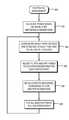
- FIG. 3is a flow chart of a method for performing an initial (first pass) allocation of power according to one embodiment of the present invention
- FIG. 4is a flow chart of a method for performing a second pass allocation of power according to one embodiment of the present invention.
- FIG. 5is a diagram of a switch with PoE power-sourcing equipment capabilities connected to devices that lack integral PoE capabilities, via Ethernet cables according to one embodiment of the present invention.
- Embodiments of the present inventionprovide improved power management in digital electronic network switches. For example, if there is insufficient power available to the switch to satisfy all power requests made to the switch, or there is a desire to limit the power provided by the switch, embodiments of the present invention may adjust the amount of power provided both to the switch's internal circuitry and to external devices connected to the switch. The power adjustment may be made based on a combination of information about the devices connected to the switch's ports, the amount of power allocated to each port via PoE, and policy information that specifies power allocation preferences.
- the general power management method summarized aboveis performed in two passes.
- the first passinitializes the system by supplying power to the switching circuitry, and via PoE, to other devices over the attached Ethernet cables based on port priority and other secondary parameters when needed.
- the second passmonitors actual power consumption and learns more about what is connected to each of the switch ports to better tune the applied priorities. As a result of the actual power measurements and the better understanding of the connected device types, a second power allocation is made.
- the power management agentcontinues to monitor network traffic and/or to send communications to attached devices to keep abreast of the attached network types, operational status, and possibly changing power needs.
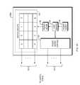
- a switch 100 bis shown in which the power to be managed comes from both the integral power supply 110 and from power supplied by other attached devices (not shown) at network connections via conductors 170 to a power input control 175 .
- the switch 100 bincludes a power management agent (not shown in FIGS. 1A and 1B , but shown in FIG. 2 ) having access to power input control 175 .
- the power meter 130measures the amount of power consumed by the switching circuits 120 , based upon which switching circuits 120 a - 120 p are enabled and operational.
- the power management agentmay request power from one or more of the external attached devices.
- the power management agentmay, for example, transmit such requests as messages sent using Ethernet packets or via signals sent along the Ethernet cable, for example by using methods in compliance with IEEE standards 802.3af or 802.3at. If power is granted from the attached devices, then the power management agent supplies additional power, received from the attached devices, to the load sharing circuitry 104 via the power input control circuitry 175 .
- the environment information gathering process 212sends and receives messages over conductors 142 using Ethernet packets to gather information about the devices connected to the switch's ports and network topology information that relates to each of the switch ports.
- the environment information gathering process 212gathers environment information by snooping on packets received by the switch 100 a or 100 b from attached devices, communicating with attached devices, and by reading topology information stored by another agent elsewhere in the network. Topology information may also be gathered from an agent (not shown) that is co-resident in the switch 100 a or 100 b.
- the power control process 214may specify the port or ports on which it prefers to receive the requested power, or it can simply state the amount of power request and allow the PoE protocol process 216 to obtain the requested power from any attached device(s) connected through the network connections via conductors 170 .
- the PoE protocol process 214then records all power received and allocated on a per switch port basis in the PoE requests data 226 .
- the power control process 214makes a second power allocation among the switch circuits 120 and, via PoE through the network connections over conductors 140 , to the other devices connected to the switch ports.
- the second power allocationmay differ from the first (initial) power allocation. If the monitoring process changes the port priorities, then power allocations may be adjusted. Other events, however, such as unplugging an external device, may also trigger re-allocation of power.
- the power management processescontinues to monitor, over the network connections via conductors 140 , network traffic and/or to send communications to devices attached to the switch ports to keep abreast of the attached device types, operational statuses, and possibly changing power needs.
- the power allocation policy 224specifies how important a port (Port Importance (PI)) is regarding both its data switching operation and its PoE power allocation.
- the policy data 224also includes a port operational priority (POP) parameter, which specifies the relative importance for operation for that port when compared to other switch ports with the same PI value.
- POPport operational priority
- PPPport PoE priority
- the power control process 214may perform an initial (first pass) power allocation among the switch ports, via conductors 140 , as follows.
- the power control process 214initializes a “remaining available power value” to be equal to the amount of power available to the switch (such as the power supplied by the power supply 110 , or the sum or the power supplied by the power supply 110 and through the power input control 175 ).
- the power control process 214identifies the set of ports sharing the highest PI value, and determines how much PoE power is requested by this set of ports.
- the power control process 214grants PoE power to all the ports in this set; otherwise the power control process 214 uses the PPP parameter value of this set of ports as a tie breaker to allocate the remaining power among this set of ports.
- the power management agent 200waits a period of time to allow devices to power up and enter an operational state. If no power has been allocated, the next PI port set is analyzed without delay. Actual power used by the switch circuitry 120 is measured and the remaining power is recalculated.
- the power management agent 200goes into data collection mode trying to glean more information over the network connections via conductors 140 about: (1) the attached device on each of the switch ports and (2) the network topology ( 302 ).
- Examples of information that the method 300 may collect about attached devicesinclude, for example, whether the attached device is an end node and, if so, what type of end node (PC, VoIP phone, Wireless AP, printer, server, etc.); whether the attached device is an intermediate device and, if so, what part of the network topology is connected through that port; and whether the port is a redundant port.
- the method 300may use these and/or other information to adjust policy data 224 such as the PI, POP, and PPP power allocation priority parameters assigned to a switch port at step ( 303 ).
- the newly adjusted power allocation parametersare used for a second pass of power allocation to re-distribute the power allocation based on the more detailed knowledge of the connected devices and the importance of each ( 304 ). All inactive ports are put in low power (sleep) mode ( 305 ). Such ports can wake up in response to LAN activities from data or PoE signaling.
- the management agent 200goes back to monitoring its environment, and after any changes, the power management agent 200 rechecks for power availability and allocation priority.
- FIG. 4a flowchart is shown of a method for utilizing power provided over the network connections via conductors 170 by external devices attached to the ports of switch 100 b ( FIG. 1B ) according to one embodiment of the present invention.
- the switch 100 bhas the capability to receive power from attached devices, and if the integral power supply 110 is insufficient to supply all the power need to power the switch circuits 120 and the PoE-requested power, then the method 400 requests power from attached devices to meet the amount of requested power that can not be supplied by the integral power supply 110 .
- the method 400allocates power to the switching circuits 120 and devices connected through the network connections via conductors 140 based on the output capabilities of the integral power supply 110 ( 401 ).
- the method 400determines whether the currently-allocated power differs from the requested power ( 402 ). If all the requests have not been met, then the method 400 requests the power shortfall from one or more devices attached to the switch ports ( 403 ). The method 400 then allocates the power received from the attached devices through the network connections via conductors 140 either to the switch ports, the attached devices, or both ( 404 ). The method 400 then reassesses the amount of power available and the amount of power needed ( 405 ), and then returns to allocating power based on the integral power supply capabilities ( 401 ).
- a switch with PoE PSE capabilities 501is connected to an Ethernet wall jack 503 via Ethernet cables 502 and 504 according to one embodiment of the present invention.
- a standard Ethernet cable 502 with RJ45 connectors on both endsconnects a cell phone charging cradle 509 to the wall jack 503 .
- the cell phone charging cradle 509is connected to cell phone 507 .
- the connection between the cell phone charging cradle 509 and the cell phone 507provides power that is provided by the switch 501 and may also provide the Ethernet data connection.
- the cell phone charging cradle 509may also have circuitry to provide information to the switch 501 indicating the power it is requesting from the switch. This circuitry can vary from a simple implementation that simply indicates that power is needed, for example the IEEE 802.3af discovery step that only requires a 25K resister, to a more complex implementation that requests a lower power than the maximum using, for example, the IEEE 802.3af power classification mechanism.
- the cell phone charging cradle 509can request one level of power to initially charge the phone quickly and then later lower its request as the batteries need less power when they are at a higher charged state.
- Embodiments of the present inventionhave a variety of advantages.
- the embodiment shown in FIG. 5has the advantage that the switch may provide power to the charger cradle 509 and/or cell phone over Ethernet cables 502 and 511 even while the cell phones 505 and 507 are turned off or otherwise incapable of sending or receiving Ethernet packets over the Ethernet cables 502 and 511 .
- the cell phones 505 and 507may easily be charged by the switch 501 without turning on the cell phones 505 and 507 , and without requiring the cell phones 505 and 507 to establish network connections through the switch 501 or to transmit any data. All of the techniques disclosed above may be used to allocate power to the charger cradle 509 and cell phone 505 along with other devices, some of which may be turned on and transmitting Ethernet traffic through the switch.
- embodiments of the present inventiondynamically monitor, assess, and trade off power allocated to the ports and to the switching circuitry in a switch, thereby avoiding the problem of allocating too much power to the switching circuitry and not enough power to the ports, and vice versa.
- portsmay be assigned different priorities so that in the event that available power is insufficient to provide power to all ports, power may be provided to the ports with the highest priorities.
- powermay be obtained from external devices over PoE and then provided to the switching circuitry or to other external devices over PoE.
- power budgets for switch operation and PoEare not pre-allocated.
- a policymay be enforced that allocates some amount of power to switch operation and another amount for delivery of PoE power to other devices.
- the above-described algorithmscould apply ceilings to the power applied to PoE and to the switching circuitry.
- the switch 100is illustrated in certain embodiments as including the integral power supply 110 , this is merely an example and does not constitute a limitation of the present invention. Alternatively or additionally, one or more external power supplies may perform the same function as the integral power supply 110 .
- the techniques described abovemay be implemented, for example, in hardware, software, firmware, or any combination thereof.
- the techniques described abovemay be implemented in one or more computer programs executing on a programmable computer including a processor, a storage medium readable by the processor (including, for example, volatile and non-volatile memory and/or storage elements), at least one input device, and at least one output device.
- Program codemay be applied to input entered using the input device to perform the functions described and to generate output.
- the outputmay be provided to one or more output devices.
- Each computer program within the scope of the claims belowmay be implemented in any programming language, such as assembly language, machine language, a high-level procedural programming language, or an object-oriented programming language.
- the programming languagemay, for example, be a compiled or interpreted programming language.
Landscapes
- Engineering & Computer Science (AREA)
- Theoretical Computer Science (AREA)
- General Engineering & Computer Science (AREA)
- Computer Networks & Wireless Communication (AREA)
- Signal Processing (AREA)
- Physics & Mathematics (AREA)
- General Physics & Mathematics (AREA)
- Computer Hardware Design (AREA)
- Small-Scale Networks (AREA)
Abstract
Description
Claims (34)
Priority Applications (4)
| Application Number | Priority Date | Filing Date | Title |
|---|---|---|---|
| US12/348,697US8205102B2 (en) | 2009-01-05 | 2009-01-05 | Intelligent power management of an intermediate network device switching circuitry and PoE delivery |
| CN201010002121.1ACN101826970B (en) | 2009-01-05 | 2010-01-05 | Intelligent power management of an intermediate network device switching circuitry and PoE delivery |
| US13/156,869US9264240B2 (en) | 2009-01-05 | 2011-06-09 | Power sharing with stackable switches |
| US13/473,168US20120228936A1 (en) | 2009-01-05 | 2012-05-16 | Intelligent power management of an intermediate network device switching circuitry and poe delivery |
Applications Claiming Priority (1)
| Application Number | Priority Date | Filing Date | Title |
|---|---|---|---|
| US12/348,697US8205102B2 (en) | 2009-01-05 | 2009-01-05 | Intelligent power management of an intermediate network device switching circuitry and PoE delivery |
Related Child Applications (1)
| Application Number | Title | Priority Date | Filing Date |
|---|---|---|---|
| US13/473,168DivisionUS20120228936A1 (en) | 2009-01-05 | 2012-05-16 | Intelligent power management of an intermediate network device switching circuitry and poe delivery |
Publications (2)
| Publication Number | Publication Date |
|---|---|
| US20100171602A1 US20100171602A1 (en) | 2010-07-08 |
| US8205102B2true US8205102B2 (en) | 2012-06-19 |
Family
ID=42311315
Family Applications (2)
| Application Number | Title | Priority Date | Filing Date |
|---|---|---|---|
| US12/348,697Active2030-10-22US8205102B2 (en) | 2009-01-05 | 2009-01-05 | Intelligent power management of an intermediate network device switching circuitry and PoE delivery |
| US13/473,168AbandonedUS20120228936A1 (en) | 2009-01-05 | 2012-05-16 | Intelligent power management of an intermediate network device switching circuitry and poe delivery |
Family Applications After (1)
| Application Number | Title | Priority Date | Filing Date |
|---|---|---|---|
| US13/473,168AbandonedUS20120228936A1 (en) | 2009-01-05 | 2012-05-16 | Intelligent power management of an intermediate network device switching circuitry and poe delivery |
Country Status (2)
| Country | Link |
|---|---|
| US (2) | US8205102B2 (en) |
| CN (1) | CN101826970B (en) |
Cited By (10)
| Publication number | Priority date | Publication date | Assignee | Title |
|---|---|---|---|---|
| US20120078690A1 (en)* | 2010-09-24 | 2012-03-29 | Harriman David J | Power allocation controller |
| US8595550B1 (en)* | 2011-03-30 | 2013-11-26 | Google Inc. | Back-up power for a network switch |
| US20140195831A1 (en)* | 2013-01-10 | 2014-07-10 | Dell Products L.P. | ADVANCED PoE POWER CONTROL |
| US9176555B2 (en) | 2013-01-30 | 2015-11-03 | Hewlett-Packard Development Company, L.P. | Power over ethernet power harvester |
| US10133648B2 (en) | 2012-11-07 | 2018-11-20 | Dell Products L.P. | Power over ethernet dynamic power allocation system |
| US11075772B2 (en) | 2015-06-30 | 2021-07-27 | Signify Holding B.V. | Supporting the commissioning of a networked power distribution system |
| US20240056320A1 (en)* | 2021-02-23 | 2024-02-15 | Phoenix Contact Development and Manufacturing, Inc. | APL Field Switch with Dynamic Power Allocation |
| US11966269B2 (en) | 2020-01-23 | 2024-04-23 | Boe Technology Group Co., Ltd. | Power supply apparatus, electronic device, and method for power supply control |
| US12294522B1 (en) | 2023-11-07 | 2025-05-06 | Mellanox Technologies, Ltd | Mitigating voltage surges in a network device by controlling port bandwidths |
| US12366909B2 (en) | 2023-05-01 | 2025-07-22 | Mellanox Technologies, Ltd | Power consumption control by toggling bandwidth shapers |
Families Citing this family (74)
| Publication number | Priority date | Publication date | Assignee | Title |
|---|---|---|---|---|
| CN101771440B (en)* | 2008-12-10 | 2014-06-11 | 华为终端有限公司 | Power line communication apparatus and control method thereof |
| US7982336B2 (en)* | 2009-02-16 | 2011-07-19 | Hewlett-Packard Company | Power sharing with stackable switches |
| US8793511B1 (en)* | 2009-03-23 | 2014-07-29 | Marvell International Ltd. | Power management for power over ethernet (PoE) system based on network communication transmission rate |
| US20100292861A1 (en)* | 2009-05-18 | 2010-11-18 | Leonard Tsai | Networked power control system |
| US20110107116A1 (en)* | 2009-11-04 | 2011-05-05 | Broadcom Corporation | System and Method for Power Over Ethernet Enabled Network Management |
| CN101902362A (en) | 2010-08-02 | 2010-12-01 | 中兴通讯股份有限公司 | Equipment management method, device and system |
| US9990019B2 (en)* | 2010-09-02 | 2018-06-05 | Philips Lighting Holding B.V. | Apparatus for powering an electrical consumer via a data connection |
| US8842574B2 (en)* | 2010-11-19 | 2014-09-23 | Marvell Israel (M.I.S.L) Ltd. | Energy efficient networking |
| CN102025511A (en)* | 2010-12-08 | 2011-04-20 | 中兴通讯股份有限公司 | Method and device for supplying power to terminal equipment |
| US8954763B2 (en)* | 2011-01-27 | 2015-02-10 | Commscope, Inc. Of North Carolina | Automated infrastructure management systems and methods for enabling real time energy management |
| EP3748810B1 (en) | 2011-05-20 | 2023-10-04 | Huawei Technologies Co., Ltd. | Intelligent power distribution system and method |
| US20130086399A1 (en)* | 2011-09-30 | 2013-04-04 | Cisco Technology, Inc. | Method, system and apparatus for network power management |
| GB2508762B (en)* | 2011-10-28 | 2020-08-12 | Hewlett Packard Development Co | Network powered device |
| CN103138946B (en)* | 2011-12-05 | 2017-05-31 | 佛山市顺德区格雷特电源有限公司 | A kind of POE power supply management methods and device |
| ES2625257T3 (en)* | 2011-12-09 | 2017-07-19 | Huawei Technologies Co., Ltd. | Method and apparatus for reducing the energy consumption of a data exchange equipment and the corresponding data exchange apparatus and equipment |
| WO2014021875A1 (en)* | 2012-07-31 | 2014-02-06 | Hewlett-Packard Development Company, L.P. | Power efficient network with network controller |
| CN102830303A (en)* | 2012-08-09 | 2012-12-19 | 深圳市双赢伟业科技股份有限公司 | Ethernet power supply testing equipment |
| CA2845423C (en) | 2012-12-28 | 2016-08-02 | Rui HUA | Power over ethernet method, apparatus, device, and system |
| US12368615B2 (en) | 2013-09-19 | 2025-07-22 | Radius Universal Llc | Fiber optic communications and power network |
| US10171180B2 (en)* | 2013-09-19 | 2019-01-01 | Radius Universal, LLC | Fiber optic communications and power network |
| US11025345B2 (en) | 2013-09-19 | 2021-06-01 | Radius Universal Llc | Hybrid cable providing data transmission through fiber optic cable and low voltage power over copper wire |
| US10855381B2 (en)* | 2013-09-19 | 2020-12-01 | Radius Universal Llc | Fiber optic communications and power network |
| US10277330B2 (en) | 2013-09-19 | 2019-04-30 | Radius Universal Llc | Fiber optic communications and power network |
| US20150169033A1 (en)* | 2013-12-13 | 2015-06-18 | Cisco Technology, Inc. | Systems and methods for power management in stackable switch |
| JP6588446B2 (en)* | 2014-01-22 | 2019-10-09 | シグニファイ ホールディング ビー ヴィ | Low complexity and low power distribution system |
| IN2014CH01483A (en)* | 2014-03-20 | 2015-09-25 | Infosys Ltd | |
| US20160197736A1 (en)* | 2015-01-02 | 2016-07-07 | Cisco Technology, Inc. | Wake-On-Link |
| WO2017030530A1 (en)* | 2015-08-14 | 2017-02-23 | Hewlett Packard Enterprise Development Lp | In-line device |
| GB2545673A (en)* | 2015-12-21 | 2017-06-28 | Canon Kk | Power management in a power over data network |
| US10382215B2 (en)* | 2015-12-22 | 2019-08-13 | Forescout Technologies, Inc. | Device identification and policy enforcement using power over ethernet (POE) |
| WO2017151314A1 (en) | 2016-03-03 | 2017-09-08 | Molex, Llc | System and method for power over ethernet control |
| US11221111B2 (en) | 2016-02-15 | 2022-01-11 | Molex, Llc | Luminaire |
| CN109075980B (en)* | 2016-03-03 | 2022-09-23 | 莫列斯有限公司 | System and method for power over ethernet control |
| CN105959122A (en)* | 2016-05-31 | 2016-09-21 | 深圳市双赢伟业科技股份有限公司 | Power supply control method and apparatus for remote power supply switch |
| FR3056050B1 (en)* | 2016-09-09 | 2019-11-01 | Slat | NETWORK SWITCH WITH POE |
| US10209763B2 (en) | 2016-09-09 | 2019-02-19 | Cisco Technology, Inc. | Power aware switching using analytics |
| WO2018080516A1 (en) | 2016-10-28 | 2018-05-03 | Hewlett-Packard Development Company, L.P. | Current monitor circuit |
| US10809134B2 (en) | 2017-05-24 | 2020-10-20 | Cisco Technology, Inc. | Thermal modeling for cables transmitting data and power |
| US11054457B2 (en) | 2017-05-24 | 2021-07-06 | Cisco Technology, Inc. | Safety monitoring for cables transmitting data and power |
| US10541758B2 (en) | 2017-09-18 | 2020-01-21 | Cisco Technology, Inc. | Power delivery through an optical system |
| US11431420B2 (en) | 2017-09-18 | 2022-08-30 | Cisco Technology, Inc. | Power delivery through an optical system |
| CN107994999B (en)* | 2017-11-29 | 2021-05-28 | 新华三技术有限公司 | PoE power management method and device |
| US11093012B2 (en) | 2018-03-02 | 2021-08-17 | Cisco Technology, Inc. | Combined power, data, and cooling delivery in a communications network |
| US10732688B2 (en) | 2018-03-09 | 2020-08-04 | Cisco Technology, Inc. | Delivery of AC power with higher power PoE (power over ethernet) systems |
| US10281513B1 (en) | 2018-03-09 | 2019-05-07 | Cisco Technology, Inc. | Verification of cable application and reduced load cable removal in power over communications systems |
| US10631443B2 (en) | 2018-03-12 | 2020-04-21 | Cisco Technology, Inc. | Splitting of combined delivery power, data, and cooling in a communications network |
| US10672537B2 (en) | 2018-03-30 | 2020-06-02 | Cisco Technology, Inc. | Interface module for combined delivery power, data, and cooling at a network device |
| US10958471B2 (en) | 2018-04-05 | 2021-03-23 | Cisco Technology, Inc. | Method and apparatus for detecting wire fault and electrical imbalance for power over communications cabling |
| US10735105B2 (en) | 2018-05-04 | 2020-08-04 | Cisco Technology, Inc. | High power and data delivery in a communications network with safety and fault protection |
| US11038307B2 (en) | 2018-05-25 | 2021-06-15 | Cisco Technology, Inc. | Cable power rating identification for power distribution over communications cabling |
| US11132040B2 (en)* | 2018-07-05 | 2021-09-28 | Microchip Technology Incorporated | Load balancing in multi-port power delivery applications |
| CN108989057A (en)* | 2018-08-02 | 2018-12-11 | 深圳市丰润达科技有限公司 | A kind of AI intelligent power supply method of POE interchanger |
| US10763749B2 (en) | 2018-11-14 | 2020-09-01 | Cisco Technology, Inc | Multi-resonant converter power supply |
| US11281282B2 (en) | 2018-11-19 | 2022-03-22 | Genetec Inc. | Intermediary device for extracting power supplied over a data connection |
| US10790997B2 (en) | 2019-01-23 | 2020-09-29 | Cisco Technology, Inc. | Transmission of pulse power and data in a communications network |
| US11061456B2 (en) | 2019-01-23 | 2021-07-13 | Cisco Technology, Inc. | Transmission of pulse power and data over a wire pair |
| US10680836B1 (en) | 2019-02-25 | 2020-06-09 | Cisco Technology, Inc. | Virtualized chassis with power-over-Ethernet for networking applications |
| US11456883B2 (en) | 2019-03-13 | 2022-09-27 | Cisco Technology, Inc. | Multiple phase pulse power in a network communications system |
| US10849250B2 (en) | 2019-03-14 | 2020-11-24 | Cisco Technology, Inc. | Integration of power, data, cooling, and management in a network communications system |
| WO2020190448A1 (en)* | 2019-03-20 | 2020-09-24 | Commscope Technologies Llc | Systems and methods for infrastructure management system based power sourcing equipment power allocation |
| CA3155694A1 (en)* | 2019-09-24 | 2021-04-01 | Genetec Inc. | Intermediary device for daisy chain and tree configuration in hybrid data/power connection |
| US11063630B2 (en) | 2019-11-01 | 2021-07-13 | Cisco Technology, Inc. | Initialization and synchronization for pulse power in a network system |
| US12126399B2 (en) | 2019-11-01 | 2024-10-22 | Cisco Technology, Inc. | Fault managed power with dynamic and adaptive fault sensor |
| US11252811B2 (en) | 2020-01-15 | 2022-02-15 | Cisco Technology, Inc. | Power distribution from point-of-load with cooling |
| US11853138B2 (en) | 2020-01-17 | 2023-12-26 | Cisco Technology, Inc. | Modular power controller |
| US11088547B1 (en) | 2020-01-17 | 2021-08-10 | Cisco Technology, Inc. | Method and system for integration and control of power for consumer power circuits |
| US11438183B2 (en) | 2020-02-25 | 2022-09-06 | Cisco Technology, Inc. | Power adapter for power supply unit |
| US11637497B2 (en) | 2020-02-28 | 2023-04-25 | Cisco Technology, Inc. | Multi-phase pulse power short reach distribution |
| US11307368B2 (en) | 2020-04-07 | 2022-04-19 | Cisco Technology, Inc. | Integration of power and optics through cold plates for delivery to electronic and photonic integrated circuits |
| US11320610B2 (en) | 2020-04-07 | 2022-05-03 | Cisco Technology, Inc. | Integration of power and optics through cold plate for delivery to electronic and photonic integrated circuits |
| US11770155B2 (en) | 2020-05-19 | 2023-09-26 | Genetec Inc. | Power distribution and data routing in a network of devices interconnected by hybrid data/power links |
| US11522727B2 (en)* | 2020-10-14 | 2022-12-06 | Juniper Networks, Inc. | Cooperative power management |
| WO2024167980A1 (en)* | 2023-02-07 | 2024-08-15 | Nanotronix Computing Inc. | Systems and methods for enhancing fiber-to-the-building/distribution point (fttb/dp) |
| CN118432961A (en)* | 2024-07-05 | 2024-08-02 | 浙江大华技术股份有限公司 | A power management method, a power management device and a computer storage medium |
Citations (13)
| Publication number | Priority date | Publication date | Assignee | Title |
|---|---|---|---|---|
| US5483656A (en)* | 1993-01-14 | 1996-01-09 | Apple Computer, Inc. | System for managing power consumption of devices coupled to a common bus |
| US20040230846A1 (en)* | 2003-05-15 | 2004-11-18 | Mancey Steven K J | System and method for the management of power supplied over data lines |
| US20050125507A1 (en)* | 2003-12-04 | 2005-06-09 | Ilan Atias | Method and apparatus for notifying end user of excess power demand |
| US20050262364A1 (en)* | 2004-05-20 | 2005-11-24 | Diab Wael W | Methods and apparatus for provisioning phantom power to remote devices |
| US20060053324A1 (en)* | 2002-10-15 | 2006-03-09 | Yaniv Giat | Rack level power management for power over Ethernet |
| US20070110360A1 (en)* | 2005-11-15 | 2007-05-17 | Linear Technology Corporation | Dynamic power allocation in system for providing power over communication link |
| US20070278857A1 (en)* | 2006-06-01 | 2007-12-06 | Steven Andrew Robbins | Mid-Link Powered Device for Power over Ethernet |
| US20080114997A1 (en)* | 2006-11-15 | 2008-05-15 | Broadcom Corporation | System and method of dynamic power management |
| US7512817B2 (en)* | 2006-01-20 | 2009-03-31 | Rit Technologies Ltd. | Management of a network supplying power over data lines |
| US20090100275A1 (en)* | 2007-10-15 | 2009-04-16 | Ray Chang | Dynamic port power allocation apparatus and methods |
| US20090172421A1 (en)* | 2007-12-26 | 2009-07-02 | Schindler Frederick R | Facilitating communication and power transfer between electrically-isolated powered device subsystems |
| US7577859B2 (en)* | 2004-02-20 | 2009-08-18 | International Business Machines Corporation | System and method of controlling power consumption in an electronic system by applying a uniquely determined minimum operating voltage to an integrated circuit rather than a predetermined nominal voltage selected for a family of integrated circuits |
| US20090327766A1 (en)* | 2008-06-30 | 2009-12-31 | Sajol Ghoshal | Power Over Ethernet Reclassification |
Family Cites Families (11)
| Publication number | Priority date | Publication date | Assignee | Title |
|---|---|---|---|---|
| US6986071B2 (en)* | 2002-02-01 | 2006-01-10 | Powerdsine, Ltd. | Detecting network power connection status using AC signals |
| US7849343B2 (en)* | 2003-06-10 | 2010-12-07 | Microsemi Corp. - Analog Mixed Signal Group Ltd. | Pre-detection of powered devices |
| US7152168B2 (en)* | 2003-08-06 | 2006-12-19 | Cisco Technology, Inc. | Recharging power storage devices with power over a network |
| US7460889B2 (en)* | 2003-10-16 | 2008-12-02 | Microsemi Corp.—Analog Mixed Signal Group Ltd. | High power classification for power over Ethernet |
| US7356588B2 (en)* | 2003-12-16 | 2008-04-08 | Linear Technology Corporation | Circuits and methods for detecting the presence of a powered device in a powered network |
| US7320078B2 (en)* | 2005-06-03 | 2008-01-15 | Cisco Technology, Inc. | Controlling delivery of power and network communications to a set of devices |
| US20070106913A1 (en)* | 2005-11-07 | 2007-05-10 | Lewis Jonathan F | Implementing power over network data link for systems utilizing multiple power sources |
| US7516340B2 (en)* | 2006-06-30 | 2009-04-07 | Silicon Laboratories, Inc. | Powered device including a classification signature resistor |
| US8006105B1 (en)* | 2006-08-02 | 2011-08-23 | American Megatrends, Inc. | AC-powered in-wall computing device with power-line networking capabilities |
| US7890777B2 (en)* | 2007-04-11 | 2011-02-15 | Broadcom Corporation | System and method for collecting power management parameters in a computing device for power over Ethernet |
| CN101141263A (en)* | 2007-08-28 | 2008-03-12 | 福建星网锐捷网络有限公司 | Method, control cell and system for controlling ethernet power supply |
- 2009
- 2009-01-05USUS12/348,697patent/US8205102B2/enactiveActive
- 2010
- 2010-01-05CNCN201010002121.1Apatent/CN101826970B/enactiveActive
- 2012
- 2012-05-16USUS13/473,168patent/US20120228936A1/ennot_activeAbandoned
Patent Citations (14)
| Publication number | Priority date | Publication date | Assignee | Title |
|---|---|---|---|---|
| US5483656A (en)* | 1993-01-14 | 1996-01-09 | Apple Computer, Inc. | System for managing power consumption of devices coupled to a common bus |
| US20060053324A1 (en)* | 2002-10-15 | 2006-03-09 | Yaniv Giat | Rack level power management for power over Ethernet |
| US20040230846A1 (en)* | 2003-05-15 | 2004-11-18 | Mancey Steven K J | System and method for the management of power supplied over data lines |
| US7155622B2 (en) | 2003-05-15 | 2006-12-26 | 3Com Corporation | System and method for the management of power supplied over data lines |
| US20050125507A1 (en)* | 2003-12-04 | 2005-06-09 | Ilan Atias | Method and apparatus for notifying end user of excess power demand |
| US7577859B2 (en)* | 2004-02-20 | 2009-08-18 | International Business Machines Corporation | System and method of controlling power consumption in an electronic system by applying a uniquely determined minimum operating voltage to an integrated circuit rather than a predetermined nominal voltage selected for a family of integrated circuits |
| US20050262364A1 (en)* | 2004-05-20 | 2005-11-24 | Diab Wael W | Methods and apparatus for provisioning phantom power to remote devices |
| US20070110360A1 (en)* | 2005-11-15 | 2007-05-17 | Linear Technology Corporation | Dynamic power allocation in system for providing power over communication link |
| US7512817B2 (en)* | 2006-01-20 | 2009-03-31 | Rit Technologies Ltd. | Management of a network supplying power over data lines |
| US20070278857A1 (en)* | 2006-06-01 | 2007-12-06 | Steven Andrew Robbins | Mid-Link Powered Device for Power over Ethernet |
| US20080114997A1 (en)* | 2006-11-15 | 2008-05-15 | Broadcom Corporation | System and method of dynamic power management |
| US20090100275A1 (en)* | 2007-10-15 | 2009-04-16 | Ray Chang | Dynamic port power allocation apparatus and methods |
| US20090172421A1 (en)* | 2007-12-26 | 2009-07-02 | Schindler Frederick R | Facilitating communication and power transfer between electrically-isolated powered device subsystems |
| US20090327766A1 (en)* | 2008-06-30 | 2009-12-31 | Sajol Ghoshal | Power Over Ethernet Reclassification |
Cited By (15)
| Publication number | Priority date | Publication date | Assignee | Title |
|---|---|---|---|---|
| US8612060B2 (en)* | 2010-09-24 | 2013-12-17 | Intel Corporation | Power allocation controller |
| US20120078690A1 (en)* | 2010-09-24 | 2012-03-29 | Harriman David J | Power allocation controller |
| US9336101B1 (en) | 2011-03-30 | 2016-05-10 | Google Inc. | Back-up power for a network switch |
| US8595550B1 (en)* | 2011-03-30 | 2013-11-26 | Google Inc. | Back-up power for a network switch |
| US10133648B2 (en) | 2012-11-07 | 2018-11-20 | Dell Products L.P. | Power over ethernet dynamic power allocation system |
| US9146613B2 (en)* | 2013-01-10 | 2015-09-29 | Dell Products L.P. | Advanced PoE power control |
| US9465425B2 (en) | 2013-01-10 | 2016-10-11 | Dell Products L.P. | Power over ethernet (POE) dynamic power supply system |
| US9678563B2 (en) | 2013-01-10 | 2017-06-13 | Dell Products L.P. | Dynamic power supply system |
| US20140195831A1 (en)* | 2013-01-10 | 2014-07-10 | Dell Products L.P. | ADVANCED PoE POWER CONTROL |
| US9176555B2 (en) | 2013-01-30 | 2015-11-03 | Hewlett-Packard Development Company, L.P. | Power over ethernet power harvester |
| US11075772B2 (en) | 2015-06-30 | 2021-07-27 | Signify Holding B.V. | Supporting the commissioning of a networked power distribution system |
| US11966269B2 (en) | 2020-01-23 | 2024-04-23 | Boe Technology Group Co., Ltd. | Power supply apparatus, electronic device, and method for power supply control |
| US20240056320A1 (en)* | 2021-02-23 | 2024-02-15 | Phoenix Contact Development and Manufacturing, Inc. | APL Field Switch with Dynamic Power Allocation |
| US12366909B2 (en) | 2023-05-01 | 2025-07-22 | Mellanox Technologies, Ltd | Power consumption control by toggling bandwidth shapers |
| US12294522B1 (en) | 2023-11-07 | 2025-05-06 | Mellanox Technologies, Ltd | Mitigating voltage surges in a network device by controlling port bandwidths |
Also Published As
| Publication number | Publication date |
|---|---|
| US20120228936A1 (en) | 2012-09-13 |
| US20100171602A1 (en) | 2010-07-08 |
| CN101826970A (en) | 2010-09-08 |
| CN101826970B (en) | 2015-02-11 |
Similar Documents
| Publication | Publication Date | Title |
|---|---|---|
| US8205102B2 (en) | Intelligent power management of an intermediate network device switching circuitry and PoE delivery | |
| US20070135086A1 (en) | Providing detailed information on powered device in system for supplying power over communication link | |
| US9100196B2 (en) | Intelligent midspan PoE injector | |
| US7966504B2 (en) | System and method for power management in a computing device for power over ethernet | |
| US7890776B2 (en) | Use of priority information to intelligently allocate power for personal computing devices in a Power-over-Ethernet system | |
| US7908495B2 (en) | System and method for implementing fairness in the powering of computing devices in a power over ethernet application | |
| US8266460B2 (en) | Layer 2 power classification support for power-over-ethernet personal computing devices | |
| EP1958375B1 (en) | Dynamic power allocation in system for providing power over communication link | |
| US8301913B2 (en) | System and method for dynamic power provisioning for a wireless access point | |
| US7890777B2 (en) | System and method for collecting power management parameters in a computing device for power over Ethernet | |
| CN101971579B (en) | Method and device for handling user terminal access in a fixed access network | |
| US20070257780A1 (en) | Inline power allocation for power over Ethernet applications | |
| US8321695B2 (en) | System and method for physical layer device enabled power over ethernet processing | |
| CN101223513A (en) | Background network bandwidth sharing behind gateway device | |
| JP2018511199A (en) | Power receiving device in power over Ethernet network system and method for said power receiving device | |
| WO2013093810A1 (en) | Bandwidth management in a home network | |
| KR20120102023A (en) | System and method for exchanging channel, physical layer and data layer information and capabilities | |
| CN113840330B (en) | Connection establishment method, gateway equipment, network system and dispatching center | |
| US20120011384A1 (en) | Network Apparatus Having Routing Function and Power Management Method Thereof | |
| CN113840331B (en) | Data transmission method, network access equipment and network system | |
| CN112202570B (en) | Switch equipment and compatible power supply method | |
| CN1762163A (en) | Method for monitoring andcontrolling a number of available decentralized IP budgets of subscriber in a packet-based com. network during and online assement of charges with limit value monitoring | |
| HK1124977A (en) | A method and system for ethernet power supplying |
Legal Events
| Date | Code | Title | Description |
|---|---|---|---|
| AS | Assignment | Owner name:3COM CORPORATION, MASSACHUSETTS Free format text:ASSIGNMENT OF ASSIGNORS INTEREST;ASSIGNORS:KABBARA, HAZEM;HISCOCK, JAMES S.;REEL/FRAME:022068/0357 Effective date:20090105 | |
| AS | Assignment | Owner name:HEWLETT-PACKARD COMPANY, CALIFORNIA Free format text:MERGER;ASSIGNOR:3COM CORPORATION;REEL/FRAME:024630/0820 Effective date:20100428 | |
| AS | Assignment | Owner name:HEWLETT-PACKARD COMPANY, CALIFORNIA Free format text:CORRECTIVE ASSIGNMENT TO CORRECT THE SEE ATTACHED;ASSIGNOR:3COM CORPORATION;REEL/FRAME:025039/0844 Effective date:20100428 | |
| AS | Assignment | Owner name:HEWLETT-PACKARD DEVELOPMENT COMPANY, L.P., TEXAS Free format text:ASSIGNMENT OF ASSIGNORS INTEREST;ASSIGNOR:HEWLETT-PACKARD COMPANY;REEL/FRAME:027329/0001 Effective date:20030131 | |
| AS | Assignment | Owner name:HEWLETT-PACKARD DEVELOPMENT COMPANY, L.P., TEXAS Free format text:CORRECTIVE ASSIGNMENT PREVIUOSLY RECORDED ON REEL 027329 FRAME 0001 AND 0044;ASSIGNOR:HEWLETT-PACKARD COMPANY;REEL/FRAME:028911/0846 Effective date:20111010 | |
| STCF | Information on status: patent grant | Free format text:PATENTED CASE | |
| AS | Assignment | Owner name:HEWLETT PACKARD ENTERPRISE DEVELOPMENT LP, TEXAS Free format text:ASSIGNMENT OF ASSIGNORS INTEREST;ASSIGNOR:HEWLETT-PACKARD DEVELOPMENT COMPANY, L.P.;REEL/FRAME:037079/0001 Effective date:20151027 | |
| FPAY | Fee payment | Year of fee payment:4 | |
| MAFP | Maintenance fee payment | Free format text:PAYMENT OF MAINTENANCE FEE, 8TH YEAR, LARGE ENTITY (ORIGINAL EVENT CODE: M1552); ENTITY STATUS OF PATENT OWNER: LARGE ENTITY Year of fee payment:8 | |
| MAFP | Maintenance fee payment | Free format text:PAYMENT OF MAINTENANCE FEE, 12TH YEAR, LARGE ENTITY (ORIGINAL EVENT CODE: M1553); ENTITY STATUS OF PATENT OWNER: LARGE ENTITY Year of fee payment:12 |