US8204634B2 - Driving dynamics control system for vehicles - Google Patents
Driving dynamics control system for vehiclesDownload PDFInfo
- Publication number
- US8204634B2 US8204634B2US10/556,575US55657504AUS8204634B2US 8204634 B2US8204634 B2US 8204634B2US 55657504 AUS55657504 AUS 55657504AUS 8204634 B2US8204634 B2US 8204634B2
- Authority
- US
- United States
- Prior art keywords
- subsystems
- central
- driver
- controller
- data
- Prior art date
- Legal status (The legal status is an assumption and is not a legal conclusion. Google has not performed a legal analysis and makes no representation as to the accuracy of the status listed.)
- Active, expires
Links
Images


Classifications
- F—MECHANICAL ENGINEERING; LIGHTING; HEATING; WEAPONS; BLASTING
- F16—ENGINEERING ELEMENTS AND UNITS; GENERAL MEASURES FOR PRODUCING AND MAINTAINING EFFECTIVE FUNCTIONING OF MACHINES OR INSTALLATIONS; THERMAL INSULATION IN GENERAL
- F16H—GEARING
- F16H61/00—Control functions within control units of change-speed- or reversing-gearings for conveying rotary motion ; Control of exclusively fluid gearing, friction gearing, gearings with endless flexible members or other particular types of gearing
- F16H61/66—Control functions within control units of change-speed- or reversing-gearings for conveying rotary motion ; Control of exclusively fluid gearing, friction gearing, gearings with endless flexible members or other particular types of gearing specially adapted for continuously variable gearings
- B—PERFORMING OPERATIONS; TRANSPORTING
- B60—VEHICLES IN GENERAL
- B60G—VEHICLE SUSPENSION ARRANGEMENTS
- B60G17/00—Resilient suspensions having means for adjusting the spring or vibration-damper characteristics, for regulating the distance between a supporting surface and a sprung part of vehicle or for locking suspension during use to meet varying vehicular or surface conditions, e.g. due to speed or load
- B60G17/015—Resilient suspensions having means for adjusting the spring or vibration-damper characteristics, for regulating the distance between a supporting surface and a sprung part of vehicle or for locking suspension during use to meet varying vehicular or surface conditions, e.g. due to speed or load the regulating means comprising electric or electronic elements
- B—PERFORMING OPERATIONS; TRANSPORTING
- B60—VEHICLES IN GENERAL
- B60T—VEHICLE BRAKE CONTROL SYSTEMS OR PARTS THEREOF; BRAKE CONTROL SYSTEMS OR PARTS THEREOF, IN GENERAL; ARRANGEMENT OF BRAKING ELEMENTS ON VEHICLES IN GENERAL; PORTABLE DEVICES FOR PREVENTING UNWANTED MOVEMENT OF VEHICLES; VEHICLE MODIFICATIONS TO FACILITATE COOLING OF BRAKES
- B60T8/00—Arrangements for adjusting wheel-braking force to meet varying vehicular or ground-surface conditions, e.g. limiting or varying distribution of braking force
- B60T8/17—Using electrical or electronic regulation means to control braking
- B60T8/1755—Brake regulation specially adapted to control the stability of the vehicle, e.g. taking into account yaw rate or transverse acceleration in a curve
- B—PERFORMING OPERATIONS; TRANSPORTING
- B60—VEHICLES IN GENERAL
- B60W—CONJOINT CONTROL OF VEHICLE SUB-UNITS OF DIFFERENT TYPE OR DIFFERENT FUNCTION; CONTROL SYSTEMS SPECIALLY ADAPTED FOR HYBRID VEHICLES; ROAD VEHICLE DRIVE CONTROL SYSTEMS FOR PURPOSES NOT RELATED TO THE CONTROL OF A PARTICULAR SUB-UNIT
- B60W40/00—Estimation or calculation of non-directly measurable driving parameters for road vehicle drive control systems not related to the control of a particular sub unit, e.g. by using mathematical models
- B60W40/08—Estimation or calculation of non-directly measurable driving parameters for road vehicle drive control systems not related to the control of a particular sub unit, e.g. by using mathematical models related to drivers or passengers
- B60W40/09—Driving style or behaviour
- B—PERFORMING OPERATIONS; TRANSPORTING
- B62—LAND VEHICLES FOR TRAVELLING OTHERWISE THAN ON RAILS
- B62D—MOTOR VEHICLES; TRAILERS
- B62D6/00—Arrangements for automatically controlling steering depending on driving conditions sensed and responded to, e.g. control circuits
- B—PERFORMING OPERATIONS; TRANSPORTING
- B62—LAND VEHICLES FOR TRAVELLING OTHERWISE THAN ON RAILS
- B62D—MOTOR VEHICLES; TRAILERS
- B62D6/00—Arrangements for automatically controlling steering depending on driving conditions sensed and responded to, e.g. control circuits
- B62D6/002—Arrangements for automatically controlling steering depending on driving conditions sensed and responded to, e.g. control circuits computing target steering angles for front or rear wheels
- B62D6/003—Arrangements for automatically controlling steering depending on driving conditions sensed and responded to, e.g. control circuits computing target steering angles for front or rear wheels in order to control vehicle yaw movement, i.e. around a vertical axis
- B—PERFORMING OPERATIONS; TRANSPORTING
- B60—VEHICLES IN GENERAL
- B60T—VEHICLE BRAKE CONTROL SYSTEMS OR PARTS THEREOF; BRAKE CONTROL SYSTEMS OR PARTS THEREOF, IN GENERAL; ARRANGEMENT OF BRAKING ELEMENTS ON VEHICLES IN GENERAL; PORTABLE DEVICES FOR PREVENTING UNWANTED MOVEMENT OF VEHICLES; VEHICLE MODIFICATIONS TO FACILITATE COOLING OF BRAKES
- B60T2260/00—Interaction of vehicle brake system with other systems
- B60T2260/02—Active Steering, Steer-by-Wire
- B—PERFORMING OPERATIONS; TRANSPORTING
- B60—VEHICLES IN GENERAL
- B60T—VEHICLE BRAKE CONTROL SYSTEMS OR PARTS THEREOF; BRAKE CONTROL SYSTEMS OR PARTS THEREOF, IN GENERAL; ARRANGEMENT OF BRAKING ELEMENTS ON VEHICLES IN GENERAL; PORTABLE DEVICES FOR PREVENTING UNWANTED MOVEMENT OF VEHICLES; VEHICLE MODIFICATIONS TO FACILITATE COOLING OF BRAKES
- B60T2260/00—Interaction of vehicle brake system with other systems
- B60T2260/06—Active Suspension System
- B—PERFORMING OPERATIONS; TRANSPORTING
- B60—VEHICLES IN GENERAL
- B60T—VEHICLE BRAKE CONTROL SYSTEMS OR PARTS THEREOF; BRAKE CONTROL SYSTEMS OR PARTS THEREOF, IN GENERAL; ARRANGEMENT OF BRAKING ELEMENTS ON VEHICLES IN GENERAL; PORTABLE DEVICES FOR PREVENTING UNWANTED MOVEMENT OF VEHICLES; VEHICLE MODIFICATIONS TO FACILITATE COOLING OF BRAKES
- B60T2260/00—Interaction of vehicle brake system with other systems
- B60T2260/08—Coordination of integrated systems
- B—PERFORMING OPERATIONS; TRANSPORTING
- B60—VEHICLES IN GENERAL
- B60T—VEHICLE BRAKE CONTROL SYSTEMS OR PARTS THEREOF; BRAKE CONTROL SYSTEMS OR PARTS THEREOF, IN GENERAL; ARRANGEMENT OF BRAKING ELEMENTS ON VEHICLES IN GENERAL; PORTABLE DEVICES FOR PREVENTING UNWANTED MOVEMENT OF VEHICLES; VEHICLE MODIFICATIONS TO FACILITATE COOLING OF BRAKES
- B60T2260/00—Interaction of vehicle brake system with other systems
- B60T2260/09—Complex systems; Conjoint control of two or more vehicle active control systems
- B—PERFORMING OPERATIONS; TRANSPORTING
- B60—VEHICLES IN GENERAL
- B60W—CONJOINT CONTROL OF VEHICLE SUB-UNITS OF DIFFERENT TYPE OR DIFFERENT FUNCTION; CONTROL SYSTEMS SPECIALLY ADAPTED FOR HYBRID VEHICLES; ROAD VEHICLE DRIVE CONTROL SYSTEMS FOR PURPOSES NOT RELATED TO THE CONTROL OF A PARTICULAR SUB-UNIT
- B60W10/00—Conjoint control of vehicle sub-units of different type or different function
- B60W10/04—Conjoint control of vehicle sub-units of different type or different function including control of propulsion units
- B—PERFORMING OPERATIONS; TRANSPORTING
- B60—VEHICLES IN GENERAL
- B60W—CONJOINT CONTROL OF VEHICLE SUB-UNITS OF DIFFERENT TYPE OR DIFFERENT FUNCTION; CONTROL SYSTEMS SPECIALLY ADAPTED FOR HYBRID VEHICLES; ROAD VEHICLE DRIVE CONTROL SYSTEMS FOR PURPOSES NOT RELATED TO THE CONTROL OF A PARTICULAR SUB-UNIT
- B60W10/00—Conjoint control of vehicle sub-units of different type or different function
- B60W10/18—Conjoint control of vehicle sub-units of different type or different function including control of braking systems
- B—PERFORMING OPERATIONS; TRANSPORTING
- B60—VEHICLES IN GENERAL
- B60W—CONJOINT CONTROL OF VEHICLE SUB-UNITS OF DIFFERENT TYPE OR DIFFERENT FUNCTION; CONTROL SYSTEMS SPECIALLY ADAPTED FOR HYBRID VEHICLES; ROAD VEHICLE DRIVE CONTROL SYSTEMS FOR PURPOSES NOT RELATED TO THE CONTROL OF A PARTICULAR SUB-UNIT
- B60W10/00—Conjoint control of vehicle sub-units of different type or different function
- B60W10/20—Conjoint control of vehicle sub-units of different type or different function including control of steering systems
- B—PERFORMING OPERATIONS; TRANSPORTING
- B60—VEHICLES IN GENERAL
- B60W—CONJOINT CONTROL OF VEHICLE SUB-UNITS OF DIFFERENT TYPE OR DIFFERENT FUNCTION; CONTROL SYSTEMS SPECIALLY ADAPTED FOR HYBRID VEHICLES; ROAD VEHICLE DRIVE CONTROL SYSTEMS FOR PURPOSES NOT RELATED TO THE CONTROL OF A PARTICULAR SUB-UNIT
- B60W10/00—Conjoint control of vehicle sub-units of different type or different function
- B60W10/22—Conjoint control of vehicle sub-units of different type or different function including control of suspension systems
- B—PERFORMING OPERATIONS; TRANSPORTING
- B60—VEHICLES IN GENERAL
- B60W—CONJOINT CONTROL OF VEHICLE SUB-UNITS OF DIFFERENT TYPE OR DIFFERENT FUNCTION; CONTROL SYSTEMS SPECIALLY ADAPTED FOR HYBRID VEHICLES; ROAD VEHICLE DRIVE CONTROL SYSTEMS FOR PURPOSES NOT RELATED TO THE CONTROL OF A PARTICULAR SUB-UNIT
- B60W50/00—Details of control systems for road vehicle drive control not related to the control of a particular sub-unit, e.g. process diagnostic or vehicle driver interfaces
- B60W2050/0001—Details of the control system
- B60W2050/0002—Automatic control, details of type of controller or control system architecture
- B60W2050/0004—In digital systems, e.g. discrete-time systems involving sampling
- B60W2050/0005—Processor details or data handling, e.g. memory registers or chip architecture
- B—PERFORMING OPERATIONS; TRANSPORTING
- B60—VEHICLES IN GENERAL
- B60W—CONJOINT CONTROL OF VEHICLE SUB-UNITS OF DIFFERENT TYPE OR DIFFERENT FUNCTION; CONTROL SYSTEMS SPECIALLY ADAPTED FOR HYBRID VEHICLES; ROAD VEHICLE DRIVE CONTROL SYSTEMS FOR PURPOSES NOT RELATED TO THE CONTROL OF A PARTICULAR SUB-UNIT
- B60W50/00—Details of control systems for road vehicle drive control not related to the control of a particular sub-unit, e.g. process diagnostic or vehicle driver interfaces
- B60W2050/0001—Details of the control system
- B60W2050/0043—Signal treatments, identification of variables or parameters, parameter estimation or state estimation
- B60W2050/0044—In digital systems
- B—PERFORMING OPERATIONS; TRANSPORTING
- B60—VEHICLES IN GENERAL
- B60W—CONJOINT CONTROL OF VEHICLE SUB-UNITS OF DIFFERENT TYPE OR DIFFERENT FUNCTION; CONTROL SYSTEMS SPECIALLY ADAPTED FOR HYBRID VEHICLES; ROAD VEHICLE DRIVE CONTROL SYSTEMS FOR PURPOSES NOT RELATED TO THE CONTROL OF A PARTICULAR SUB-UNIT
- B60W50/00—Details of control systems for road vehicle drive control not related to the control of a particular sub-unit, e.g. process diagnostic or vehicle driver interfaces
- B60W50/02—Ensuring safety in case of control system failures, e.g. by diagnosing, circumventing or fixing failures
- B60W50/029—Adapting to failures or work around with other constraints, e.g. circumvention by avoiding use of failed parts
- B60W2050/0297—Control Giving priority to different actuators or systems
- B—PERFORMING OPERATIONS; TRANSPORTING
- B60—VEHICLES IN GENERAL
- B60W—CONJOINT CONTROL OF VEHICLE SUB-UNITS OF DIFFERENT TYPE OR DIFFERENT FUNCTION; CONTROL SYSTEMS SPECIALLY ADAPTED FOR HYBRID VEHICLES; ROAD VEHICLE DRIVE CONTROL SYSTEMS FOR PURPOSES NOT RELATED TO THE CONTROL OF A PARTICULAR SUB-UNIT
- B60W2710/00—Output or target parameters relating to a particular sub-units
- B60W2710/20—Steering systems
Definitions
- the present inventionrelates to a driving dynamics control system for vehicles, including at least one signal distribution to which vehicle data, environment data and data regarding the driver's request are sent in the form of input data, and including several controllable or regulatable subsystems which modify the dynamics of the vehicle such as a driver-independently adjustable steering system, a driver-independently adjustable chassis, a driver-independently adjustable brake, and a driver-independently adjustable driving track.
- the number of subsystems for influencing or improving the driving performance or the driving dynamics and for improving safetyis significantly rising.
- the trend to more electronics and electromechanicscan also be found in the subsystems for influencing the driving performance or driving dynamics, respectively.
- the subsystems that allow influencing the driving performance activelythat means irrespective of the driver, are the electronic brake system, the active steering system, active and semi-active chassis components, and also the driving system in vehicles with controllable intermediate gears.
- Each of these subsystemsis meant to influence the vehicle in such a manner that improvements in the driving performance are achieved.
- the control algorithmshave their focus in different fields (safety, handling, or comfort). Therefore, the subsystems are primarily tuned only for their respective control target or their main range of application, respectively.
- the ranges of application or the focuses of the individual subsystemsoverlap each other, however, in wide ranges of the driving dynamics-related range of application of vehicles.
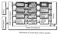
- Each of these subsystemsworks on its own (stand-alone), although frequently the same driving dynamics quantities are intended to be influenced or controlled ( FIG. 1 relating to the example of the horizontal control). This causes a very great complexity of application, above all for the mutual protection of the individual subsystems with respect to each other, and results in functional restrictions for each subsystem (i.e. each subsystem is unable to reach its control target in an ideal manner because it must not limit or hinder the other subsystems).
- an object of the inventioninvolves enhancing the functionality of a driving dynamics control.
- a driving dynamics control system for a vehicleinclude a signal distribution, two or more controllable subsystems which modify dynamics of the vehicle and a central determining unit that actuates the controllable subsystems based on a control target.
- the divisionis carried out by the central driving condition controller or the regulating variable distribution itself.
- the driving condition controller or the regulating variable distributionis a multivariable controller, and the corresponding division of the control requests among the individual subsystems is based on the controller design (controller concept, controller approach, controller algorithm) itself, on a quality criterion or optimization criterion predetermined to the controller and/or by means of tunable weighting factors (weighting corresponding to intensity and activation order of the subsystems).
- the controller designcontroller concept, controller approach, controller algorithm
- tunable weighting factorsweighting corresponding to intensity and activation order of the subsystems.
- it may be the objective of this divisionthat in the presence of a minor tendency to instability, the stabilization request is first of all assigned to the chassis and the steering system for comfort reasons. When there is a greater tendency to instability, the brake and the driving track, respectively, must additionally be taken into account.
- FIG. 1depicts a horizontal control system for a driving system:
- FIG. 2depicts a control system
- the optimal interplay between the individual subsystemsresults in an optimal control performance or an optimal attainment of the control targets when looking upon all functions of the vehicle.
- All primary control functions of the individual subsystemsare grouped (integrated) centrally in a control algorithm in order to ensure optimal interaction of the individual subsystems.
- control of vehicle condition variablesare combined centrally in a control algorithm.
- the individual subsystems(brake system, steering system, chassis system, and drive system) become intelligent actuators.
- the control of the driving dynamics conditionis performed based on a central primary control algorithm which purposefully addresses the individual intelligent actuators in order to reach its control targets.
- An intelligent actuatornot only adjusts nominal values of the primary driving dynamics controller but also reports its current condition and its still possible adjusting potential back to the primary driving dynamics controller, enabling the primary driving dynamics controller to take this data into account in its control strategy.
- each intelligent actuatorhas basic functions. These basic functions in turn are pure controls, that means, they act without feedback of driving dynamics variables. For example, this concerns the electronic brake force distribution in the brake system, it concerns a speed-responsive variation of the steering ratio in an active steering system, or it concerns the distribution of roll moments controlled by the lateral acceleration in a chassis system with active stabilizers. All control functions or feedbacks and adjustments of driving dynamics variables are executed in the central driving dynamics control algorithm. The determination of the current driving condition and the determination of the driver's request also take place centrally in a block connected upstream of the primary driving dynamics controller ( FIG. 2 ).
- FIG. 2shows a driving dynamics control 10 according to the invention including a signal distribution 11 .
- the signal distributionreceives input data from the vehicle (measured variables such as the lateral acceleration, the yaw rate), from the driver 13 (direction requested by the driver by way of steering angle and/or accelerator pedal position, brake pedal position), and from the environment 14 (if measurable e.g. the angle of inclination of the roadway, the coefficient of friction of the roadway, etc.).
- the signal distribution 11is connected to a determining unit 15 (driving condition detection, driver request detection) and the regulating variable distribution or the determining unit of the central driving condition controller 16 and the subsystems 17 to 20 .
- the determining unit 15is supplied with input data of the systems driver, vehicle and environment, and the determining unit 15 determines from this signal the nominal performance of the vehicle as desired by the driver as well as non-measurable condition and environment variables (e.g. coefficient of friction of the roadway) and sends these variables to the central driving condition controller in block 16 .
- the regulating variable distribution or the central driving condition controller 16respectively, communicates interactively with the signal distribution 11 and also sends to it data about the regulating variables. Said data can be fed back to the determining unit 15 .
- the regulating variable distribution or the central driving condition controlleris connected interactively with each of the subsystems and this way conveys its control commands to the individual chassis subsystems, yet receives also this way information about their condition (e.g.
- the subsystems 17 - 20adjust the control commands of the central driving condition controller and furnish in turn the actual values or the adjusted or the actual condition of the respective subsystem, respectively, to the signal distribution 11 which in turn sends this information in the closed control loop to the determining unit 15 (driving condition detection and signal conditioning).
Landscapes
- Engineering & Computer Science (AREA)
- Mechanical Engineering (AREA)
- Transportation (AREA)
- General Engineering & Computer Science (AREA)
- Physics & Mathematics (AREA)
- Mathematical Physics (AREA)
- Combustion & Propulsion (AREA)
- Chemical & Material Sciences (AREA)
- Automation & Control Theory (AREA)
- Control Of Driving Devices And Active Controlling Of Vehicle (AREA)
- Steering Control In Accordance With Driving Conditions (AREA)
- Vehicle Body Suspensions (AREA)
- Regulating Braking Force (AREA)
Abstract
Description
- The different subsystems or intelligent actuators, respectively, are actuated by a control algorithm closed in itself in the integrated approach. Thus, the harmonious interaction of the individual intelligent actuators is structurally protected. The control of the driving condition is protected because the individual intelligent actuators corresponding to the multivariable controller approach cannot mutually influence each other negatively.
- There is a simple possibility of extending the central driving dynamics controller by new intelligent actuators because the increase in complexity is insignificant.
- The mutual consideration of the intelligent actuators in the control approach results in a reduced complexity of application (in stand-alone subsystems the actuators must be protected against each other by driving tests). The complexity rises enormously in extensions of the stand-alone subsystem network, what shows above all in a highly increasing complexity of application.
- The central network of the individual intelligent actuators in the control approach results in a low bus load and a small number of physical interfaces between the central processor and the intelligent actuators. If the stand-alone systems were ‘network-connected’, this would cause an extent of communication among the stand-alone systems which is difficult to control and attend to.
- The shift and combination or integration, respectively, of all control functions, driving condition detections, and driver interpretations of the subsystems into a central control unit saves costs. The individual intelligent actuators require less calculating efforts in order to execute their basic functions (control operations). Thus, less costly and nearly wattless calculator units with less physical memory requirements can be used in the intelligent actuators.
- The effort needed for the extension and servicing of the entire software provided in the vehicle is reduced, because it is no longer required that each subsystem has control algorithms of its own, a driving condition determining unit and a driver request detection, as is the case with the stand-alone subsystems. The control algorithms, the driving condition determining unit and the driver request detection need being extended and attended to only one time in a central fashion in the integrated approach.
- A clear-cut and unambiguous separation of basic functions (controls) and driving dynamics control functions (adjustment of driving condition variables by means of feedback of variables relevant for driving dynamics such as the yaw rate, lateral acceleration, sideslip angle, etc.).
Claims (8)
Applications Claiming Priority (7)
| Application Number | Priority Date | Filing Date | Title |
|---|---|---|---|
| DE10321645 | 2003-05-13 | ||
| DE10321645.6 | 2003-05-13 | ||
| DE10321645 | 2003-05-13 | ||
| DE10341412.6 | 2003-09-05 | ||
| DE10341412 | 2003-09-05 | ||
| DE10341412ADE10341412A1 (en) | 2003-05-13 | 2003-09-05 | Vehicle dynamics control system for vehicles |
| PCT/EP2004/050735WO2004101337A1 (en) | 2003-05-13 | 2004-05-07 | Driving dynamics control system for vehicles |
Publications (2)
| Publication Number | Publication Date |
|---|---|
| US20070150116A1 US20070150116A1 (en) | 2007-06-28 |
| US8204634B2true US8204634B2 (en) | 2012-06-19 |
Family
ID=33453855
Family Applications (1)
| Application Number | Title | Priority Date | Filing Date |
|---|---|---|---|
| US10/556,575Active2028-03-08US8204634B2 (en) | 2003-05-13 | 2004-05-07 | Driving dynamics control system for vehicles |
Country Status (7)
| Country | Link |
|---|---|
| US (1) | US8204634B2 (en) |
| EP (1) | EP1628864B1 (en) |
| JP (1) | JP4611987B2 (en) |
| KR (1) | KR101195011B1 (en) |
| BR (1) | BRPI0410220A (en) |
| RU (1) | RU2005137540A (en) |
| WO (1) | WO2004101337A1 (en) |
Cited By (11)
| Publication number | Priority date | Publication date | Assignee | Title |
|---|---|---|---|---|
| US20110035129A1 (en)* | 2009-08-05 | 2011-02-10 | Advics Co., Ltd. | Motion control device for vehicle |
| US20130261874A1 (en)* | 2012-04-01 | 2013-10-03 | Zonar Systems, Inc. | Method and apparatus for matching vehicle ecu programming to current vehicle operating conditions |
| US20140039758A1 (en)* | 2012-08-04 | 2014-02-06 | Audi Ag | Method and device for operating a chassis |
| US20150046060A1 (en)* | 2013-08-12 | 2015-02-12 | Mitsubishi Electric Research Laboratories, Inc. | Method and System for Adjusting Vehicle Settings |
| US9229906B2 (en) | 2012-04-01 | 2016-01-05 | Zonar Systems, Inc. | Method and apparatus for matching vehicle ECU programming to current vehicle operating conditions |
| US9358986B2 (en) | 2012-04-01 | 2016-06-07 | Zonar Systems, Inc. | Method and apparatus for changing either driver behavior or vehicle behavior based on current vehicle location and zone definitions created by a remote user |
| US9527515B2 (en) | 2011-12-23 | 2016-12-27 | Zonar Systems, Inc. | Vehicle performance based on analysis of drive data |
| US9747254B2 (en) | 2012-04-01 | 2017-08-29 | Zonar Systems, Inc. | Method and apparatus for matching vehicle ECU programming to current vehicle operating conditions |
| US10056008B1 (en) | 2006-06-20 | 2018-08-21 | Zonar Systems, Inc. | Using telematics data including position data and vehicle analytics to train drivers to improve efficiency of vehicle use |
| US10431020B2 (en) | 2010-12-02 | 2019-10-01 | Zonar Systems, Inc. | Method and apparatus for implementing a vehicle inspection waiver program |
| US11485407B2 (en) | 2019-05-16 | 2022-11-01 | Lightning Systems, Inc. | Smart electronic power steering system and method for a retrofitted electric vehicle |
Families Citing this family (10)
| Publication number | Priority date | Publication date | Assignee | Title |
|---|---|---|---|---|
| JP2005297622A (en)* | 2004-04-07 | 2005-10-27 | Toyoda Mach Works Ltd | Steering system |
| DE102005025287A1 (en)* | 2005-06-02 | 2006-12-07 | Continental Teves Ag & Co. Ohg | Driving condition adapted, based on steering intervention driving dynamics control |
| DE102005026477A1 (en)* | 2005-06-09 | 2006-12-14 | Zf Friedrichshafen Ag | Signal processing system with fast signal processing |
| US7970512B2 (en)* | 2006-08-30 | 2011-06-28 | Ford Global Technologies | Integrated control system for stability control of yaw, roll and lateral motion of a driving vehicle using an integrated sensing system with pitch information |
| EP1936656A1 (en)* | 2006-12-21 | 2008-06-25 | Nederlandse Organisatie voor Toegepast-Natuuurwetenschappelijk Onderzoek TNO | Plasma generator and method for cleaning an object |
| US8473156B2 (en) | 2008-10-17 | 2013-06-25 | Continental Teves Ag & Co. Ohg | Driving dynamics control system for vehicles |
| DE102009049635A1 (en) | 2009-10-15 | 2011-04-21 | Continental Teves Ag & Co. Ohg | System for regulating driving dynamic e.g. longitudinal dynamic, of motor vehicle, has actuators whose state is supplied to distribution algorithm to provide adjusting potential and speed of actuators for conversion of regulating parameter |
| JP5617615B2 (en) | 2010-12-27 | 2014-11-05 | 株式会社デンソー | In-vehicle control device |
| WO2013100122A1 (en)* | 2011-12-28 | 2013-07-04 | 日産自動車株式会社 | Vehicle control device |
| JP5900601B2 (en)* | 2012-02-24 | 2016-04-06 | トヨタ自動車株式会社 | Vehicle behavior control device |
Citations (5)
| Publication number | Priority date | Publication date | Assignee | Title |
|---|---|---|---|---|
| US6070687A (en)* | 1998-02-04 | 2000-06-06 | Trw Inc. | Vehicle occupant restraint device, system, and method having an anti-theft feature |
| US6213567B1 (en)* | 1998-02-02 | 2001-04-10 | Siemens Aktiengesellschaft | Brake system for a motor vehicle and method for transmitting data in an electrically controlled brake system for a motor vehicle |
| WO2002100698A1 (en) | 2001-06-13 | 2002-12-19 | Ricardo Mtc Limited | Improvements in vehicle control |
| WO2003106235A1 (en) | 2002-06-15 | 2003-12-24 | Robert Bosch Gmbh | Driving stability management by a vehicle regulator system |
| US6873891B2 (en)* | 2000-05-23 | 2005-03-29 | Daimlerchrysler Ag | Method and device for co-ordinating multiple driving system devices of a vehicle |
Family Cites Families (9)
| Publication number | Priority date | Publication date | Assignee | Title |
|---|---|---|---|---|
| JP2834808B2 (en)* | 1989-12-08 | 1998-12-14 | 三菱電機株式会社 | Automotive control device |
| DE19749005A1 (en)* | 1997-06-30 | 1999-01-07 | Bosch Gmbh Robert | Method and device for regulating movement variables representing vehicle movement |
| DE19812238A1 (en)* | 1998-03-20 | 1999-09-23 | Daimler Chrysler Ag | Procedure for controlling the yaw behavior of vehicles |
| JP4570192B2 (en)* | 2000-02-08 | 2010-10-27 | ユニバーサル造船株式会社 | Thrust generator control method and control device |
| JP3838048B2 (en)* | 2001-04-16 | 2006-10-25 | 日産自動車株式会社 | Vehicle travel control device |
| DE10132440A1 (en)* | 2001-07-04 | 2003-01-23 | Bosch Gmbh Robert | System and method for monitoring the driving behavior of a vehicle |
| JP3596493B2 (en)* | 2001-08-09 | 2004-12-02 | 日産自動車株式会社 | Travel control device for vehicles |
| DE10143551A1 (en)* | 2001-09-06 | 2003-03-27 | Daimler Chrysler Ag | Device for controlling vehicle equipment has at least one software module for processing data components in longitudinal direction, at least one for processing data in transverse direction |
| JP3956693B2 (en)* | 2001-12-27 | 2007-08-08 | トヨタ自動車株式会社 | Integrated vehicle motion controller |
- 2004
- 2004-05-07BRBRPI0410220-7Apatent/BRPI0410220A/ennot_activeApplication Discontinuation
- 2004-05-07KRKR1020057021562Apatent/KR101195011B1/ennot_activeExpired - Lifetime
- 2004-05-07WOPCT/EP2004/050735patent/WO2004101337A1/enactiveApplication Filing
- 2004-05-07JPJP2006530178Apatent/JP4611987B2/ennot_activeExpired - Lifetime
- 2004-05-07RURU2005137540/11Apatent/RU2005137540A/ennot_activeApplication Discontinuation
- 2004-05-07USUS10/556,575patent/US8204634B2/enactiveActive
- 2004-05-07EPEP04741529.4Apatent/EP1628864B1/ennot_activeExpired - Lifetime
Patent Citations (5)
| Publication number | Priority date | Publication date | Assignee | Title |
|---|---|---|---|---|
| US6213567B1 (en)* | 1998-02-02 | 2001-04-10 | Siemens Aktiengesellschaft | Brake system for a motor vehicle and method for transmitting data in an electrically controlled brake system for a motor vehicle |
| US6070687A (en)* | 1998-02-04 | 2000-06-06 | Trw Inc. | Vehicle occupant restraint device, system, and method having an anti-theft feature |
| US6873891B2 (en)* | 2000-05-23 | 2005-03-29 | Daimlerchrysler Ag | Method and device for co-ordinating multiple driving system devices of a vehicle |
| WO2002100698A1 (en) | 2001-06-13 | 2002-12-19 | Ricardo Mtc Limited | Improvements in vehicle control |
| WO2003106235A1 (en) | 2002-06-15 | 2003-12-24 | Robert Bosch Gmbh | Driving stability management by a vehicle regulator system |
Cited By (20)
| Publication number | Priority date | Publication date | Assignee | Title |
|---|---|---|---|---|
| US10056008B1 (en) | 2006-06-20 | 2018-08-21 | Zonar Systems, Inc. | Using telematics data including position data and vehicle analytics to train drivers to improve efficiency of vehicle use |
| US10223935B2 (en) | 2006-06-20 | 2019-03-05 | Zonar Systems, Inc. | Using telematics data including position data and vehicle analytics to train drivers to improve efficiency of vehicle use |
| US8909450B2 (en) | 2009-08-05 | 2014-12-09 | Advics Co., Ltd. | Motion control device for vehicle |
| US20110035129A1 (en)* | 2009-08-05 | 2011-02-10 | Advics Co., Ltd. | Motion control device for vehicle |
| US8639427B2 (en)* | 2009-08-05 | 2014-01-28 | Advics Co., Ltd. | Motion control device for vehicle |
| US10431020B2 (en) | 2010-12-02 | 2019-10-01 | Zonar Systems, Inc. | Method and apparatus for implementing a vehicle inspection waiver program |
| US9527515B2 (en) | 2011-12-23 | 2016-12-27 | Zonar Systems, Inc. | Vehicle performance based on analysis of drive data |
| US10507845B2 (en) | 2011-12-23 | 2019-12-17 | Zonar Systems, Inc. | Method and apparatus for changing vehicle behavior based on current vehicle location and zone definitions created by a remote user |
| US10099706B2 (en) | 2011-12-23 | 2018-10-16 | Zonar Systems, Inc. | Method and apparatus for changing vehicle behavior based on current vehicle location and zone definitions created by a remote user |
| US20130261874A1 (en)* | 2012-04-01 | 2013-10-03 | Zonar Systems, Inc. | Method and apparatus for matching vehicle ecu programming to current vehicle operating conditions |
| US9358986B2 (en) | 2012-04-01 | 2016-06-07 | Zonar Systems, Inc. | Method and apparatus for changing either driver behavior or vehicle behavior based on current vehicle location and zone definitions created by a remote user |
| US9747254B2 (en) | 2012-04-01 | 2017-08-29 | Zonar Systems, Inc. | Method and apparatus for matching vehicle ECU programming to current vehicle operating conditions |
| US9229906B2 (en) | 2012-04-01 | 2016-01-05 | Zonar Systems, Inc. | Method and apparatus for matching vehicle ECU programming to current vehicle operating conditions |
| US10061745B2 (en) | 2012-04-01 | 2018-08-28 | Zonar Sytems, Inc. | Method and apparatus for matching vehicle ECU programming to current vehicle operating conditions |
| US10289651B2 (en) | 2012-04-01 | 2019-05-14 | Zonar Systems, Inc. | Method and apparatus for matching vehicle ECU programming to current vehicle operating conditions |
| US8914184B2 (en)* | 2012-04-01 | 2014-12-16 | Zonar Systems, Inc. | Method and apparatus for matching vehicle ECU programming to current vehicle operating conditions |
| US20140039758A1 (en)* | 2012-08-04 | 2014-02-06 | Audi Ag | Method and device for operating a chassis |
| US8762000B2 (en)* | 2012-08-04 | 2014-06-24 | Audi Ag | Method and device for operating a chassis |
| US20150046060A1 (en)* | 2013-08-12 | 2015-02-12 | Mitsubishi Electric Research Laboratories, Inc. | Method and System for Adjusting Vehicle Settings |
| US11485407B2 (en) | 2019-05-16 | 2022-11-01 | Lightning Systems, Inc. | Smart electronic power steering system and method for a retrofitted electric vehicle |
Also Published As
| Publication number | Publication date |
|---|---|
| KR101195011B1 (en) | 2012-10-31 |
| JP2007512991A (en) | 2007-05-24 |
| KR20070066819A (en) | 2007-06-27 |
| EP1628864A1 (en) | 2006-03-01 |
| US20070150116A1 (en) | 2007-06-28 |
| JP4611987B2 (en) | 2011-01-12 |
| BRPI0410220A (en) | 2006-05-09 |
| RU2005137540A (en) | 2006-04-27 |
| WO2004101337A1 (en) | 2004-11-25 |
| EP1628864B1 (en) | 2015-03-25 |
Similar Documents
| Publication | Publication Date | Title |
|---|---|---|
| US8204634B2 (en) | Driving dynamics control system for vehicles | |
| EP2205457B1 (en) | Method and system for influencing the movement of a motor vehicle body, the chain of movements of which can be controlled or adjusted, and associated vehicle | |
| US7689337B2 (en) | Cooperative vehicle control system | |
| KR101288749B1 (en) | Driving condition adapted to the steering engagement based on vehicle dynamic control | |
| US8121756B2 (en) | Device and method for driving dynamics control in a vehicle | |
| US7305292B2 (en) | Coordination of a vehicle dynamics control system with other vehicles stability systems | |
| JP2003534196A (en) | Method and apparatus for coordinating multiple driving system devices of a vehicle | |
| WO2010100761A1 (en) | Vehicle travel control device | |
| US6208926B1 (en) | Method and apparatus for controlling the brake system of a vehicle | |
| CN1787939B (en) | Driving dynamics control system for vehicles | |
| US12139220B2 (en) | Method for operating a steering system | |
| US7032981B2 (en) | Control system for a vehicle | |
| US8364346B2 (en) | Method and device for roll stabilization of a motor vehicle | |
| CN117043029A (en) | Method and device for operating a vehicle | |
| EP1798127B1 (en) | Cooperative vehicle control system | |
| US20250242648A1 (en) | Control system and method for vehicle suspension | |
| US20240246539A1 (en) | Method for operating an active roll support system of a motor vehicle | |
| US20250313052A1 (en) | Suspension system with hold control | |
| DE102008052992B4 (en) | Method and system for influencing the movement of a vehicle body of a motor vehicle and vehicle whose movement sequences can be controlled or regulated | |
| CN119325434A (en) | Method and adjusting device for automatic braking adjustment of motor vehicle | |
| CN119562913A (en) | Method for operating a central computer of a vehicle | |
| CN115515805A (en) | Driving dynamics control of a vehicle by means of a damper | |
| JPH0781356A (en) | Fluid pressure active suspension |
Legal Events
| Date | Code | Title | Description |
|---|---|---|---|
| AS | Assignment | Owner name:CONTINENTAL TEVES AG & CO., OHG, GERMANY Free format text:ASSIGNMENT OF ASSIGNORS INTEREST;ASSIGNORS:SCHWARZ, DR. RALF;FRITZ, DR. STEFAN;SCHRABLER, DR. SIEGHARD;AND OTHERS;REEL/FRAME:018692/0959 Effective date:20050921 | |
| STCF | Information on status: patent grant | Free format text:PATENTED CASE | |
| FEPP | Fee payment procedure | Free format text:PAYOR NUMBER ASSIGNED (ORIGINAL EVENT CODE: ASPN); ENTITY STATUS OF PATENT OWNER: LARGE ENTITY | |
| FPAY | Fee payment | Year of fee payment:4 | |
| MAFP | Maintenance fee payment | Free format text:PAYMENT OF MAINTENANCE FEE, 8TH YEAR, LARGE ENTITY (ORIGINAL EVENT CODE: M1552); ENTITY STATUS OF PATENT OWNER: LARGE ENTITY Year of fee payment:8 | |
| MAFP | Maintenance fee payment | Free format text:PAYMENT OF MAINTENANCE FEE, 12TH YEAR, LARGE ENTITY (ORIGINAL EVENT CODE: M1553); ENTITY STATUS OF PATENT OWNER: LARGE ENTITY Year of fee payment:12 | |
| AS | Assignment | Owner name:CONTINENTAL AUTOMOTIVE TECHNOLOGIES GMBH, GERMANY Free format text:MERGER AND CHANGE OF NAME;ASSIGNORS:CONTINENTAL TEVES AG & CO. OHG;CONTINENTAL AUTOMOTIVE TECHNOLOGIES GMBH;REEL/FRAME:068794/0001 Effective date:20220714 |