US8204622B2 - Entertainment media rental and return system and a removable storage bin therefor - Google Patents
Entertainment media rental and return system and a removable storage bin thereforDownload PDFInfo
- Publication number
- US8204622B2 US8204622B2US12/641,791US64179109AUS8204622B2US 8204622 B2US8204622 B2US 8204622B2US 64179109 AUS64179109 AUS 64179109AUS 8204622 B2US8204622 B2US 8204622B2
- Authority
- US
- United States
- Prior art keywords
- terminal
- return
- rental
- entertainment media
- dvd
- Prior art date
- Legal status (The legal status is an assumption and is not a legal conclusion. Google has not performed a legal analysis and makes no representation as to the accuracy of the status listed.)
- Expired - Fee Related, expires
Links
Images


Classifications
- G—PHYSICS
- G11—INFORMATION STORAGE
- G11B—INFORMATION STORAGE BASED ON RELATIVE MOVEMENT BETWEEN RECORD CARRIER AND TRANSDUCER
- G11B17/00—Guiding record carriers not specifically of filamentary or web form, or of supports therefor
- G11B17/22—Guiding record carriers not specifically of filamentary or web form, or of supports therefor from random access magazine of disc records
- G11B17/225—Guiding record carriers not specifically of filamentary or web form, or of supports therefor from random access magazine of disc records wherein the disks are transferred from a fixed magazine to a fixed playing unit using a moving carriage
- G—PHYSICS
- G07—CHECKING-DEVICES
- G07F—COIN-FREED OR LIKE APPARATUS
- G07F17/00—Coin-freed apparatus for hiring articles; Coin-freed facilities or services
- G07F17/16—Coin-freed apparatus for hiring articles; Coin-freed facilities or services for devices exhibiting advertisements, announcements, pictures or the like
- G—PHYSICS
- G07—CHECKING-DEVICES
- G07F—COIN-FREED OR LIKE APPARATUS
- G07F7/00—Mechanisms actuated by objects other than coins to free or to actuate vending, hiring, coin or paper currency dispensing or refunding apparatus
- G07F7/06—Mechanisms actuated by objects other than coins to free or to actuate vending, hiring, coin or paper currency dispensing or refunding apparatus by returnable containers, i.e. reverse vending systems in which a user is rewarded for returning a container that serves as a token of value, e.g. bottles
- G07F7/069—Mechanisms actuated by objects other than coins to free or to actuate vending, hiring, coin or paper currency dispensing or refunding apparatus by returnable containers, i.e. reverse vending systems in which a user is rewarded for returning a container that serves as a token of value, e.g. bottles by box-like containers, e.g. videocassettes, books
- G—PHYSICS
- G11—INFORMATION STORAGE
- G11B—INFORMATION STORAGE BASED ON RELATIVE MOVEMENT BETWEEN RECORD CARRIER AND TRANSDUCER
- G11B17/00—Guiding record carriers not specifically of filamentary or web form, or of supports therefor
- G11B17/22—Guiding record carriers not specifically of filamentary or web form, or of supports therefor from random access magazine of disc records
- G11B17/221—Guiding record carriers not specifically of filamentary or web form, or of supports therefor from random access magazine of disc records with movable magazine
- G11B17/223—Guiding record carriers not specifically of filamentary or web form, or of supports therefor from random access magazine of disc records with movable magazine in a vertical direction
Definitions
- the present inventionrelates to media on which entertainment data is stored, such as a digital versatile disc (“DVD”), and is particularly directed to an entertainment media rental and return system and a removable storage bin therefor.
- DVDdigital versatile disc
- a typical self-service media rental terminal for renting DVDsis capable of both dispensing a rented DVD to a customer and receiving a returned DVD from a customer.
- the self-service media rental terminalhas a customer interface by which a customer interacts with the terminal to rent DVDs and return DVDs.
- a drawback in known self-service media rental terminals which are capable of both dispensing rented DVDs and receiving returned DVDsis that a customer who just wants to return a DVD has to wait in a queue with other customers who want to rent (or both rent and return) DVDs at the terminal. This wait in a queue may be quite frustrating for the customer who just wants to return a DVD, especially if the queue is relatively long. It would be desirable to provide an improved way for a customer who just wants to return a DVD.
- an entertainment media rental and return systemcomprises a rental terminal at which a customer can either rent entertainment media or return entertainment media which has been previously rented from the rental terminal, a return terminal at which a customer can only return entertainment media which has been previously rented from the rental terminal, and a removable storage bin interchangeable between the terminals and arranged to (i) receive entertainment media which has been returned by a customer at the return terminal when the bin is installed in the return terminal, (ii) receive entertainment media which has been returned by a customer at the rental terminal when the bin is installed in the rental terminal, and (iii) provide entertainment media which is available to be rented to a customer at the rental terminal when the bin is installed in the rental terminal.
- FIG. 1is a right-front perspective view of a dedicated self-service return terminal for receiving a returned DVD on which entertainment data is stored, and which return terminal is constructed in accordance with one embodiment of the present invention
- FIG. 2is a perspective view similar to FIG. 1 , and shows a back-lit message display removed to better illustrate certain internal components of the dedicated self-service return terminal;
- FIG. 3is a perspective view similar to FIG. 2 , and shows a bare DVD being inserted into a slot of a bare disc transporter;
- FIG. 4is a perspective view similar to FIG. 3 , and shows a cased DVD being inserted into a slot of a cased disc transporter;
- FIG. 5is a perspective view, looking approximately in the direction of arrow “X” in FIG. 1 , and showing a left-back perspective view of the dedicated self-service return terminal;
- FIG. 6is a perspective view similar to FIG. 5 , and shows a number of panels removed to better illustrate a removable DVD cartridge bin;
- FIG. 7is a perspective view similar to FIG. 6 , and showing the removable DVD cartridge bin in another position;
- FIG. 8is a perspective view similar to FIG. 8 , and showing the removable DVD cartridge bin in yet another position;
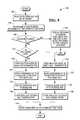
- FIG. 9is a flow diagram which depicts typical operation of the dedicated self-service return terminal of FIG. 1 ;
- FIG. 10is a perspective view similar to FIG. 1 , and showing a lower access door of the dedicated self-service return terminal in an open position;
- FIG. 11is a perspective view similar to FIG. 10 , and showing the removable DVD cartridge bin of FIG. 8 removed from the dedicated self-service return terminal;
- FIG. 12is a perspective view of a system which pictorially illustrates how the DVD cartridge bin shown in FIG. 11 is moved from the dedicated self-service return terminal to a main self-service rental terminal which is associated with the dedicated self-service return terminal.
- the present inventionrelates to media on which entertainment data is stored, such as a digital versatile disc (“DVD”), and is particularly directed to an entertainment media rental and return system and a removable storage bin therefor.
- DVDdigital versatile disc
- the dedicated self-service return terminal 10constructed in accordance with one embodiment of the present invention is illustrated.
- the dedicated self-service return terminal 10is capable of only receiving returned DVDs, and is not capable of dispensing DVDs.
- the self-service return terminal 10comprises an exterior enclosure 12 which has a main panel 14 to which an upper customer interface panel 16 is fastened and to which a lower front access panel 18 is hingedly fastened.
- a first shutter mechanismhas a first shutter door 24 movable between an open position and a closed position.
- a second shutter mechanismhas a second shutter door 26 movable between an open position and a closed position.
- a backlit message display 20is provided on the upper customer interface panel 16 .
- the display 20may be in the form of a liquid crystal display (LCD).
- the display 20provides instructions for a customer desiring to return a DVD. As shown in FIG. 1 , the display 20 is displaying an instruction line “PLEASE INSERT DISC BELOW”.
- a radio frequency identification (RFID) reader 22is also provided on the upper customer interface panel 16 .
- the RFID reader 22is located underneath the upper panel 16 , and is therefore shown in dotted line.
- a fixed label marked “PLEASE SCAN DISC HERE”is adjacent to the RFID reader 22 .
- a bare DVD transporter 30has a first media return slot 31 which is aligned with the first shutter door 24 ( FIG. 1 ) of the first shutter mechanism.
- a cased DVD transporter 32has a second media return slot 33 which is aligned with the second shutter door 26 of the second shutter mechanism.
- a controller 35controls the first shutter mechanism to move the first shutter door 24 from the closed position to the opened position to allow a returned bare DVD (i.e., a DVD which is by itself without a case) to be inserted through the first media return slot 31 of the bare DVD transporter 30 .
- the controller 35maintains the first shutter door 24 in the closed position.
- the controller 35also controls the second shutter mechanism to move the second shutter door 26 from the closed position to the open position to allow a returned cased DVD (i.e., a DVD which is in a DVD storage case) to be inserted through the second media return slot 33 of the cased DVD transporter 32 .
- the controller 35maintains the second shutter door 26 in the closed position.
- the controller 35may comprise an electronic processor, a microcomputer, or the like. Such devices are known and, therefore, will not be described further.
- the first shutter door 24opens and the customer inserts the bare DVD through the first media return slot 31 .
- the second shutter door 26opens and the customer inserts the cased DVD through the second media return slot 33 .
- Structure and operation of the bare DVD transporter 30 and the cased DVD transporter 32are known and, therefore, will not be described further.
- structure and operation of the first and second shutter doors 24 , 26 of the first and second shutter mechanismsare known and, therefore, will not be described further.
- a container 34has a chamber in which a removable disc storage bin 40 is installed when the storage bin is in use in the terminal 10 .
- the removable storage bin 40includes a first bin portion 42 which is aligned with the bare DVD transporter 30 to receive bare DVDs to be returned through the bare DVD transporter.
- a bare DVD 36is shown aligned with the first media return slot 31 and is ready to be inserted through the slot into the bare DVD transporter 30 to return the bare DVD.
- the removable storage bin 40also includes a second bin portion 44 which is aligned with the cased DVD transporter 32 to receive cased DVDs to be returned through the cased DVD transporter. As shown in FIG.
- a cased DVD 38is shown aligned with the second media return slot 33 and is ready to be inserted through the slot into the cased DVD transporter 32 to return the cased DVD.
- Each of the first and second bin portions 42 , 44has a linear array of shelves. The array of shelves of the first bin portion 42 and the array of shelves of the second bin portion 44 are substantially the same.
- FIG. 5is a perspective view, looking approximately in the direction of arrow “X” in FIG. 1 . More specifically, FIG. 5 shows a left-back perspective view of the dedicated self-service return terminal 10 .
- FIG. 6is a perspective view similar to FIG. 5 , and shows the main panel 14 ( FIG. 1 ) removed to better illustrate internal components of the dedicated self-service return terminal 10 .
- an internal frame 48supports a sliding mechanism 50 which, in turn, supports the container 34 for vertically sliding movement between a topmost position (as shown in FIG. 7 ) and a bottommost position (as shown in FIG. 8 ).
- the container 34is in a default and stowed position when it is in its bottommost position shown in FIG. 8 .
- the container 34 shown in FIG. 6is in some intermediate position between the topmost position of FIG. 7 and the bottommost position of FIG. 8 .
- the first and second bin portions 42 , 44 of the storage bin 40are in position for receiving either a returned bare DVD from the bare DVD transporter 30 or a returned cased DVD from the cased DVD transporter 32 .
- the sliding mechanism 50comprises a pair of parallel rails 52 which extend vertically.
- One side of the container 34is slidably coupled to one of the rails 52
- an opposite side of the containeris slidably coupled to the other one of the rails.
- a direct current (DC) motor 54is drivingly coupled through an endless continuous belt 56 to the container 34 .
- the controller 35controls the DC motor 54 in known manner to rotate in one direction to move the container 34 along the rails 52 towards the topmost position of the container ( FIG. 7 ), and to rotate in the opposite direction to move the container along the rails 52 towards the bottommost position of the container ( FIG. 8 ).
- the RFID reader 22( FIG. 1 ) reads data from a DVD (bare or cased) intended to be returned by a customer arriving at the self-service return terminal 10 and “swiping” the DVD in front of the RFID reader (step 102 ). Based upon the data read from the DVD, the controller 35 ( FIG. 2 ) makes a determination as to whether the DVD is being returned to the correct location (steps 104 and 106 ). If the determination is negative (i.e., the DVD is not being returned to the correct location), then a message is displayed on the display 20 to inform the customer that the DVD is not being returned to the correct location (step 108 ).
- step 110determines whether the DVD is a bare DVD. If the determination in step 110 is affirmative (i.e., the DVD being returned is a bare DVD), then the controller 35 controls the first shutter mechanism to move the first shutter door 24 from the closed position to the open position to allow the bare DVD to be inserted through the first media return slot 31 into the bare DVD transporter 30 (step 120 ). The controller 35 then controls the DC motor 54 to move the container 34 from the bottommost position (i.e., its stowed position) shown in FIG. 8 to a position such as shown in FIG.
- the controller 35controls the first shutter mechanism to close the first shutter door 24 (step 126 ).
- the controller 35then controls the DC motor 54 to move the container 34 back to its stowed position shown in FIG. 8 (step 140 ).
- step 110determines whether the DVD being returned is a cased DVD.
- the controller 35controls the second shutter mechanism to move the second shutter door 26 from the closed position to the open position to allow the cased DVD to be inserted through the second media return slot 33 into the cased DVD transporter 32 (step 130 ).
- the controller 35then controls the DC motor 54 to move the container 34 from the bottommost position shown in FIG. 8 to a position such as shown in FIG. 6 so that the returned cased DVD can be received and stored in a shelf of the second bin portion 42 of the storage bin 40 (step 132 ).
- the controller 35controls the second shutter mechanism to close the second shutter door 26 (step 136 ).
- the controller 35then controls the DC motor 54 to move the container 34 back to its stowed position shown in FIG. 8 (step 140 ).
- the lower front access panel 18is shown opened and the container 34 is in its stowed position.
- the storage bin 40can be easily removed and uninstalled from the container, such as shown by arrow “A” in FIG. 11 .
- the removed storage bin 40can then be rotated around (as depicted by arrow “B”), and then installed into a self-service rental terminal 90 (as depicted by arrow “C”).
- the self-service rental terminal 90is a full-featured DVD rental terminal at which a customer can only rent DVDs (or possibly both rent and return DVDs).
- the dedicated self-service rental terminal 10 and the full-featured self-service rental terminal 90are separate and spaced apart from each other.
- the dedicated self-service return terminal 10 described hereinaboveis conveniently provided for a customer who just wants to return a DVD.
- the customer who just wants to return a DVDneed not have to wait in line with other customers who want to either rent or both rent and return DVDs at a full-featured self-service rental terminal such as shown in FIG. 12 .
- both the first and second shutter doors 24 , 26are maintained in their closed positions until only after the RFID reader 22 has verified the DVD is being returned to the correct location. This helps to keep a customer from returning a DVD to the wrong location. This also helps to keep non-customers from placing junk and trash into the slots of the bare DVD transporter 30 and the cased DVD transporter 32 , and thereby vandalizing the terminal 10 . Such a vandalized terminal may be unable to operate until a service person has been called and arrives at the terminal to clean out the junk and trash.
- the bottommost position of the container 34 shown in FIG. 8maintains the storage bin 40 at a relatively low center of gravity. This bottommost position also makes the storage bin 40 easily available for servicing when the lower front access panel 18 is opened.
- the above-descriptiondescribes the bottommost position of the container 34 as being the default position of the storage bin 40 , it is conceivable that a position which other than the bottommost position be the default position.
- the container 34can be positioned at numerous intermediate positions between the topmost and bottommost positions. Typically, the number of different intermediate positions is directly related to the maximum number of shelves available each of the first and second bin portions 42 , 44 of the storage bin 40 .
- design of the dedicated self-service return terminal 10allows a relatively full storage bin 40 to be easily removed from the dedicated self-service return terminal 10 and then quickly moved to the full-featured self-service rental terminal 90 ( FIG. 11 ), without having to empty contents of the full storage bin.
- This interchangeability feature of the removable storage bin 40allows a service person to quickly and efficiently service both the dedicated self-service return terminal 10 and the full-featured self-service rental terminal 90 .
- the dedicated self-service return terminalmay be any type of device in a publicly accessible, unattended environment.
- Dedicated self-service return terminalsare generally public-access devices that are designed to allow a customer to return a media item (such as a bared DVD or a cased DVD) on which entertainment data is stored.
- Dedicated self-service return terminalstypically include some form of tamper resistance so that they are inherently resilient.
- Dedicated self-service return terminalsallow a customer to more quickly return a media item on which entertainment data is stored without having to wait in line with customers who want to rent (or both rent and return) media items on which entertainment data is stored.
- entertainment mediain the form of a DVD being returned, it is conceivable that other types of entertainment media may be returned.
- the entertainment mediamay comprise a flash memory which stores entertainment data.
- the entertainment mediamay comprise optical media which is other than a DVD.
- Entertainment mediamay be of different technologies, different forms, or different sizes.
Landscapes
- Physics & Mathematics (AREA)
- General Physics & Mathematics (AREA)
- Engineering & Computer Science (AREA)
- Multimedia (AREA)
- Coin-Freed Apparatuses For Hiring Articles (AREA)
Abstract
Description
Claims (5)
Priority Applications (2)
| Application Number | Priority Date | Filing Date | Title |
|---|---|---|---|
| US12/641,791US8204622B2 (en) | 2009-12-18 | 2009-12-18 | Entertainment media rental and return system and a removable storage bin therefor |
| EP20100193029EP2348492B1 (en) | 2009-12-18 | 2010-11-29 | Entertainment media rental and return system and a removable storage bin therefor |
Applications Claiming Priority (1)
| Application Number | Priority Date | Filing Date | Title |
|---|---|---|---|
| US12/641,791US8204622B2 (en) | 2009-12-18 | 2009-12-18 | Entertainment media rental and return system and a removable storage bin therefor |
Publications (2)
| Publication Number | Publication Date |
|---|---|
| US20110147400A1 US20110147400A1 (en) | 2011-06-23 |
| US8204622B2true US8204622B2 (en) | 2012-06-19 |
Family
ID=44149646
Family Applications (1)
| Application Number | Title | Priority Date | Filing Date |
|---|---|---|---|
| US12/641,791Expired - Fee RelatedUS8204622B2 (en) | 2009-12-18 | 2009-12-18 | Entertainment media rental and return system and a removable storage bin therefor |
Country Status (1)
| Country | Link |
|---|---|
| US (1) | US8204622B2 (en) |
Cited By (6)
| Publication number | Priority date | Publication date | Assignee | Title |
|---|---|---|---|---|
| US20120271453A1 (en)* | 2005-05-31 | 2012-10-25 | Vigix, Inc. | Systems, methods, and devices for dispensing products from a kiosk |
| USD681030S1 (en)* | 2012-07-11 | 2013-04-30 | Ncr Corporation | Kiosk |
| US20130131862A1 (en)* | 2011-08-23 | 2013-05-23 | Vendrx, Inc. | Beneficial Product Dispenser |
| US20130184856A1 (en)* | 2011-07-29 | 2013-07-18 | Dave Gregerson | Digital media rental and return kiosk having a three-position lockable gate mechanism and methods of operating a digital media rental and return kiosk |
| USD806163S1 (en)* | 2015-06-15 | 2017-12-26 | Videojet Technologies Inc. | Printer cabinet |
| WO2019212509A1 (en)* | 2018-04-30 | 2019-11-07 | Hewlett-Packard Development Company, L.P. | Service kiosk device provisioning |
Citations (9)
| Publication number | Priority date | Publication date | Assignee | Title |
|---|---|---|---|---|
| US4812629A (en)* | 1985-03-06 | 1989-03-14 | Term-Tronics, Incorporated | Method and apparatus for vending |
| US5159560A (en)* | 1990-06-25 | 1992-10-27 | Newell William C | Automated merchandise dispensing and retrieval system |
| US6201474B1 (en)* | 1998-10-21 | 2001-03-13 | Intermec Ip Corp. | Magnetic tape storage media having RFID transponders |
| US20020046122A1 (en)* | 2000-05-25 | 2002-04-18 | Barber William H. | System and kiosk for commerce of optical media through multiple locations |
| US6529453B1 (en)* | 1998-06-24 | 2003-03-04 | Sony Corporation | Content providing system |
| US20040254676A1 (en)* | 2003-06-11 | 2004-12-16 | Touch Automation | Automated business system and method of vending and returning a consumer product |
| US20060259192A1 (en)* | 2005-04-22 | 2006-11-16 | Lowe J M | System and method for regulating vendible media products |
| US20090326708A1 (en)* | 2008-06-26 | 2009-12-31 | Rudy Alan T | System and method for remotely buying, renting, and/or selling media discs |
| US7860606B2 (en)* | 2008-05-02 | 2010-12-28 | Intogreat Companies, Inc. | System and method for remotely dispensing media discs having an inventory management system |
- 2009
- 2009-12-18USUS12/641,791patent/US8204622B2/ennot_activeExpired - Fee Related
Patent Citations (12)
| Publication number | Priority date | Publication date | Assignee | Title |
|---|---|---|---|---|
| US4812629A (en)* | 1985-03-06 | 1989-03-14 | Term-Tronics, Incorporated | Method and apparatus for vending |
| US5159560A (en)* | 1990-06-25 | 1992-10-27 | Newell William C | Automated merchandise dispensing and retrieval system |
| US6529453B1 (en)* | 1998-06-24 | 2003-03-04 | Sony Corporation | Content providing system |
| US6201474B1 (en)* | 1998-10-21 | 2001-03-13 | Intermec Ip Corp. | Magnetic tape storage media having RFID transponders |
| US20020046122A1 (en)* | 2000-05-25 | 2002-04-18 | Barber William H. | System and kiosk for commerce of optical media through multiple locations |
| US20040254676A1 (en)* | 2003-06-11 | 2004-12-16 | Touch Automation | Automated business system and method of vending and returning a consumer product |
| US20060259192A1 (en)* | 2005-04-22 | 2006-11-16 | Lowe J M | System and method for regulating vendible media products |
| US20060272922A1 (en)* | 2005-04-22 | 2006-12-07 | Eric Hoersten | System and method for offline vending of a media product |
| US7747346B2 (en)* | 2005-04-22 | 2010-06-29 | Redbox Automated Retail, Llc | System and method for regulating vendible media products |
| US7853354B2 (en)* | 2005-04-22 | 2010-12-14 | Redbox Automated Retail, Llc | System and method for communicating vending information |
| US7860606B2 (en)* | 2008-05-02 | 2010-12-28 | Intogreat Companies, Inc. | System and method for remotely dispensing media discs having an inventory management system |
| US20090326708A1 (en)* | 2008-06-26 | 2009-12-31 | Rudy Alan T | System and method for remotely buying, renting, and/or selling media discs |
Cited By (10)
| Publication number | Priority date | Publication date | Assignee | Title |
|---|---|---|---|---|
| US20120271453A1 (en)* | 2005-05-31 | 2012-10-25 | Vigix, Inc. | Systems, methods, and devices for dispensing products from a kiosk |
| US20130184856A1 (en)* | 2011-07-29 | 2013-07-18 | Dave Gregerson | Digital media rental and return kiosk having a three-position lockable gate mechanism and methods of operating a digital media rental and return kiosk |
| US9478091B2 (en)* | 2011-07-29 | 2016-10-25 | Ncr Corporation | Digital media rental and return kiosk having a three-position lockable gate mechanism and methods of operating a digital media rental and return kiosk |
| US20130131862A1 (en)* | 2011-08-23 | 2013-05-23 | Vendrx, Inc. | Beneficial Product Dispenser |
| US10102706B2 (en)* | 2011-08-23 | 2018-10-16 | Vendrx, Inc. | Beneficial product dispenser |
| US10789803B2 (en) | 2011-08-23 | 2020-09-29 | Vendrx, Inc. | Beneficial product dispenser |
| USD681030S1 (en)* | 2012-07-11 | 2013-04-30 | Ncr Corporation | Kiosk |
| USD806163S1 (en)* | 2015-06-15 | 2017-12-26 | Videojet Technologies Inc. | Printer cabinet |
| WO2019212509A1 (en)* | 2018-04-30 | 2019-11-07 | Hewlett-Packard Development Company, L.P. | Service kiosk device provisioning |
| US11436568B2 (en) | 2018-04-30 | 2022-09-06 | Hewlett-Packard Development Company, L.P. | Service kiosk device provisioning |
Also Published As
| Publication number | Publication date |
|---|---|
| US20110147400A1 (en) | 2011-06-23 |
Similar Documents
| Publication | Publication Date | Title |
|---|---|---|
| US8346387B2 (en) | Dedicated self-service return terminal and method of operating a dedicated self-service return terminal for receiving returned media on which entertainment data is stored | |
| US8204622B2 (en) | Entertainment media rental and return system and a removable storage bin therefor | |
| US8113421B2 (en) | Dedicated self-service return terminal and method of operating a dedicated self-service return terminal for receiving returned media on which entertainment data is stored | |
| US8463432B2 (en) | Self-service media rental terminal and method of operating a self-service media rental terminal having a plurality of customer interfaces | |
| US9652923B2 (en) | ADA compliance in vending machines | |
| US9640014B2 (en) | Vending machine with elevator delivery of vended product to customer access | |
| US9044106B1 (en) | Storage and retrieval system and methods | |
| US20180268358A1 (en) | Order fulfillment system and method with item sensor | |
| US20120127307A1 (en) | Controllable Kiosk Return Gate | |
| US20160200517A1 (en) | Order Fulfillment System and Method | |
| CN111971716B (en) | Automatic dispenser of edible products and/or durable goods | |
| US6994230B2 (en) | Rear loading vending machine | |
| US9569911B2 (en) | Secondary media return system and method | |
| US20020074397A1 (en) | Vending machine with age verification means | |
| EP2348492B1 (en) | Entertainment media rental and return system and a removable storage bin therefor | |
| AU2018269927B2 (en) | Order fulfillment system and method with item sensor | |
| JP4577440B2 (en) | Vending machine product storage rack | |
| CN211237017U (en) | Automatic vending machine | |
| JP2009093479A (en) | Vending machine | |
| JP3700370B2 (en) | Vending machine product storage device | |
| CN215068433U (en) | Multi-surface vending machine | |
| JP4433839B2 (en) | vending machine | |
| CN112466040B (en) | Unmanned sales counter and unmanned sales counter limiting layer frame thereof | |
| KR20250055925A (en) | Smart cell with built-in UWB communication module | |
| JP2011123766A (en) | Automatic vending machine |
Legal Events
| Date | Code | Title | Description |
|---|---|---|---|
| AS | Assignment | Owner name:NCR CORPORATION, OHIO Free format text:ASSIGNMENT OF ASSIGNORS INTEREST;ASSIGNORS:YEPEZ, RAFAEL;MASTRY, JASON A.;SIGNING DATES FROM 20100118 TO 20100130;REEL/FRAME:023913/0782 | |
| STCF | Information on status: patent grant | Free format text:PATENTED CASE | |
| AS | Assignment | Owner name:JPMORGAN CHASE BANK, N.A., AS ADMINISTRATIVE AGENT, ILLINOIS Free format text:SECURITY AGREEMENT;ASSIGNORS:NCR CORPORATION;NCR INTERNATIONAL, INC.;REEL/FRAME:032034/0010 Effective date:20140106 Owner name:JPMORGAN CHASE BANK, N.A., AS ADMINISTRATIVE AGENT Free format text:SECURITY AGREEMENT;ASSIGNORS:NCR CORPORATION;NCR INTERNATIONAL, INC.;REEL/FRAME:032034/0010 Effective date:20140106 | |
| FPAY | Fee payment | Year of fee payment:4 | |
| AS | Assignment | Owner name:JPMORGAN CHASE BANK, N.A., ILLINOIS Free format text:SECURITY AGREEMENT;ASSIGNORS:NCR CORPORATION;NCR INTERNATIONAL, INC.;REEL/FRAME:038646/0001 Effective date:20160331 | |
| FEPP | Fee payment procedure | Free format text:MAINTENANCE FEE REMINDER MAILED (ORIGINAL EVENT CODE: REM.); ENTITY STATUS OF PATENT OWNER: LARGE ENTITY | |
| LAPS | Lapse for failure to pay maintenance fees | Free format text:PATENT EXPIRED FOR FAILURE TO PAY MAINTENANCE FEES (ORIGINAL EVENT CODE: EXP.); ENTITY STATUS OF PATENT OWNER: LARGE ENTITY | |
| STCH | Information on status: patent discontinuation | Free format text:PATENT EXPIRED DUE TO NONPAYMENT OF MAINTENANCE FEES UNDER 37 CFR 1.362 | |
| FP | Lapsed due to failure to pay maintenance fee | Effective date:20200619 | |
| AS | Assignment | Owner name:NCR VOYIX CORPORATION, GEORGIA Free format text:RELEASE OF PATENT SECURITY INTEREST;ASSIGNOR:JPMORGAN CHASE BANK, N.A., AS ADMINISTRATIVE AGENT;REEL/FRAME:065346/0531 Effective date:20231016 Owner name:BANK OF AMERICA, N.A., AS ADMINISTRATIVE AGENT, NORTH CAROLINA Free format text:SECURITY INTEREST;ASSIGNOR:NCR VOYIX CORPORATION;REEL/FRAME:065346/0168 Effective date:20231016 | |
| AS | Assignment | Owner name:NCR VOYIX CORPORATION, GEORGIA Free format text:CHANGE OF NAME;ASSIGNOR:NCR CORPORATION;REEL/FRAME:065820/0704 Effective date:20231013 |