US8204353B2 - Apparatus and methods for tracking and analyzing digital recording device event sequences - Google Patents
Apparatus and methods for tracking and analyzing digital recording device event sequencesDownload PDFInfo
- Publication number
- US8204353B2 US8204353B2US11/138,576US13857605AUS8204353B2US 8204353 B2US8204353 B2US 8204353B2US 13857605 AUS13857605 AUS 13857605AUS 8204353 B2US8204353 B2US 8204353B2
- Authority
- US
- United States
- Prior art keywords
- information
- storage device
- mass storage
- address
- data bus
- Prior art date
- Legal status (The legal status is an assumption and is not a legal conclusion. Google has not performed a legal analysis and makes no representation as to the accuracy of the status listed.)
- Expired - Fee Related, expires
Links
- 238000000034methodMethods0.000titleclaimsabstractdescription30
- 238000004891communicationMethods0.000claimsabstractdescription21
- 230000015654memoryEffects0.000claimsdescription58
- 230000004044responseEffects0.000claimsdescription8
- 230000003287optical effectEffects0.000claimsdescription2
- 238000013507mappingMethods0.000claims1
- 230000001902propagating effectEffects0.000claims1
- 238000012545processingMethods0.000description31
- 238000010586diagramMethods0.000description18
- 230000006399behaviorEffects0.000description13
- 230000003111delayed effectEffects0.000description13
- 238000003780insertionMethods0.000description6
- 230000037431insertionEffects0.000description6
- 230000008859changeEffects0.000description5
- 238000000605extractionMethods0.000description5
- 230000008569processEffects0.000description5
- 238000012546transferMethods0.000description5
- 230000007423decreaseEffects0.000description4
- 230000009471actionEffects0.000description2
- 238000004458analytical methodMethods0.000description2
- 238000005259measurementMethods0.000description2
- 230000003068static effectEffects0.000description2
- 230000003044adaptive effectEffects0.000description1
- 230000005540biological transmissionEffects0.000description1
- 238000001514detection methodMethods0.000description1
- 239000000284extractSubstances0.000description1
- 230000006870functionEffects0.000description1
- 238000012005ligant binding assayMethods0.000description1
- 238000012544monitoring processMethods0.000description1
- 230000000737periodic effectEffects0.000description1
- 239000007787solidSubstances0.000description1
- 230000005236sound signalEffects0.000description1
Images


Classifications
- H—ELECTRICITY
- H04—ELECTRIC COMMUNICATION TECHNIQUE
- H04H—BROADCAST COMMUNICATION
- H04H60/00—Arrangements for broadcast applications with a direct linking to broadcast information or broadcast space-time; Broadcast-related systems
- H04H60/29—Arrangements for monitoring broadcast services or broadcast-related services
- H04H60/33—Arrangements for monitoring the users' behaviour or opinions
- H—ELECTRICITY
- H04—ELECTRIC COMMUNICATION TECHNIQUE
- H04N—PICTORIAL COMMUNICATION, e.g. TELEVISION
- H04N5/00—Details of television systems
- H04N5/76—Television signal recording
- H—ELECTRICITY
- H04—ELECTRIC COMMUNICATION TECHNIQUE
- H04N—PICTORIAL COMMUNICATION, e.g. TELEVISION
- H04N5/00—Details of television systems
- H04N5/76—Television signal recording
- H04N5/78—Television signal recording using magnetic recording
- H04N5/781—Television signal recording using magnetic recording on disks or drums
- H—ELECTRICITY
- H04—ELECTRIC COMMUNICATION TECHNIQUE
- H04N—PICTORIAL COMMUNICATION, e.g. TELEVISION
- H04N5/00—Details of television systems
- H04N5/76—Television signal recording
- H04N5/84—Television signal recording using optical recording
- H04N5/85—Television signal recording using optical recording on discs or drums
- H—ELECTRICITY
- H04—ELECTRIC COMMUNICATION TECHNIQUE
- H04N—PICTORIAL COMMUNICATION, e.g. TELEVISION
- H04N5/00—Details of television systems
- H04N5/76—Television signal recording
- H04N5/907—Television signal recording using static stores, e.g. storage tubes or semiconductor memories
Definitions
- the present disclosurerelates generally to digital recording devices and, more particularly, to apparatus and methods for tracking and analyzing digital recording device event sequences.
- Television ratings informationis typically generated by collecting viewing records or other viewing information from a group of statistically selected households.
- Each of the statistically selected householdstypically has a data logging and processing unit commonly referred to as a “home unit.”
- the home unitis often in communication with a variety of attachments that provide inputs to the home unit or receive outputs from the home unit.
- a source identification unitsuch as a frequency detector attachment, which is a well-known device, may be in communication with a television to sense a local oscillator frequency of the television tuner. In this manner, the frequency detector attachment may be used to determine if the television is operating (i.e., is turned on) and to determine to which channel the television is currently tuned based on a detected frequency.
- a people counterwhich is also a well-known device, may be located in the viewing space of the television and in communication with the home unit, thereby enabling the home unit to detect the identities of the persons currently viewing programs displayed on the television.
- the home unitusually processes the inputs (e.g., channel tuning information, viewer identities, etc.) from the attachments to produce viewing records.
- Viewing recordsmay be generated on a periodic basis (i.e., at fixed time intervals) or may be generated in response to a change in an input such as, for example, a change in the identities of the persons viewing the television, a change in the channel tuning information (i.e., a channel change), etc.
- each viewing recordtypically contains channel information such as a station or channel number and a time (e.g., a date and time of day) at which the channel was viewed.
- viewing recordsmay contain other information such as the identities of viewers present at the viewing time.
- the home unitcollects a quantity of viewing records and transmits collected viewing records, usually daily, to a central office or data processing facility for further processing or analysis.
- the central data processing facilityreceives viewing records from home units located in some or all of the statistically selected households and analyzes the viewing records to ascertain the viewing behaviors of a particular household or a particular group of households selected from all participating households. Additionally, the central data processing facility may generate viewing behavior statistics and other parameters indicative of viewing behavior associated with all of the participating households.
- the central office or data processing facilitycompares reference data such as a list of programs (i.e., a schedule of television programming or television guide) to the viewing records. In this manner, the central office can infer which program was viewed by matching the time and channel information in a viewing record to the program associated with that same time and channel in the program schedule. Such a matching process can be carried out for each of the viewing records received by the central office, thereby enabling the central office to reconstruct what programs were watched by all participating households and the times at which the programs were watched.
- reference datasuch as a list of programs (i.e., a schedule of television programming or television guide)
- While known apparatus and techniques for ascertaining the viewing behavior of a large populationare well suited for viewing records associated with live viewing of television programming, these techniques are not suitable for use with audio and video programs that are recorded and then later viewed.
- the viewing timeis delayed with respect to the time at which the program information was available as a live program.
- viewing records containing viewing time informationcannot be compared to reference program guide information at the central office to infer what programs are associated with the viewing records.
- the tuning information available from, for example, a frequency detector attachment in communication with a television that is being used to display a previously recorded programdoes not provide useful tuning information.
- the recorded programis typically supplied by a video recorder (e.g., a VCR) or the like that sends unmodulated low-level video and audio signals to the video and audio inputs of the television that bypass the tuner circuitry of the television.
- DVRsdigital video recorders
- PVRspersonal video recorders
- TiVoTM systemThe use of digital video recorders (DVRs) and personal video recorders (PVRs) such as the TiVoTM system further complicates collection of viewing behavior information because viewers in households with these types of recording devices can rapidly change between live viewing of a program, a somewhat delayed viewing of a program, fast forwarding and rewinding a program, pausing a program, and recording a program for later viewing while watching another program live.
- processing techniques based on recognition of program signatureshas been employed in some cases where it is difficult to obtain accurate tuning information and in cases where it may otherwise be difficult to obtain viewing time information and channel information associated with the currently viewed program content. Unfortunately, these techniques are not well suited for use in situations where a recording device enables rapid changes between live viewing of a program, delayed viewing of the program, viewing of another program while recording the program, etc.
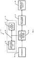
- FIG. 1is a block diagram of an example system that can be used to track a sequence of events associated with a digital recording device
- FIG. 2is a more detailed block diagram of an example digital information monitor/analyzer that may be used as the digital information monitor/analyzer shown in FIG. 1 ;
- FIG. 3is a detailed block diagram of another example digital information monitor/analyzer that may be used as the digital information monitor/analyzer shown in FIG. 1 ;
- FIG. 4is a flow diagram illustrating one example manner in which the digital video information monitor/analyzer devices shown in FIGS. 1 , 2 and 3 may be configured to generate event records and a sequence of events record;
- FIG. 5is a flow diagram of another example manner in which the digital information monitor/analyzer devices shown in FIGS. 1 , 2 and 3 may be configured to generate a sequence of events record;
- FIG. 6is a block diagram of an example header packet insertion/extraction apparatus that may be used within one or more of the digital information monitor/analyzer devices shown in FIGS. 1 , 2 and 3 to carry out the example method shown in FIG. 5 ;
- FIG. 7is a flow diagram of an example manner in which the header packet insertion/extraction apparatus shown in FIG. 6 may be used within the information monitor/analyzer devices shown in FIGS. 1 , 2 and 3 to generate a sequence of events record;
- FIG. 8is a block diagram of an example system that uses a digital information monitor/analyzer in conjunction with a DVR and an audience measurement unit;
- FIG. 9is a graph that depicts an example of live viewing of a video program via a DVR
- FIG. 10is a graph that depicts an example of delayed viewing of video program via a DVR
- FIG. 11is a graph that depicts an example relationship between view time and delay time for the paused and rewind operations of a DVR;
- FIG. 12is a graph that depicts an example relationship between view time and delay time for a fast forward operation of a DVR
- FIG. 13is a graph of example viewing behavior associated with a DVR.
- FIG. 14is a flow diagram of an example method that can be used by the digital information monitor/analyzer devices shown in FIGS. 1 , 2 and 3 to enable discrimination between initially paused operation and live viewing operation of a DVR.
- FIG. 1is a block diagram of an example system 10 that can be used to track a sequence of events associated with a digital recording device 12 .
- the system 10includes a digital information monitor/analyzer 14 , one or more attachments 16 , a data logger/processor 18 and a central data processing facility 20 .
- the digital recording device 12includes a local data processing unit 22 and a mass storage device 24 that are coupled via a data bus 26 .
- the digital recording device 12may be a digital video recorder (DVR) or a personal video recorder (PVR), both of which are well-known devices.
- DVRdigital video recorder
- PVRpersonal video recorder
- a PVRis a DVR that has been configured to be automatically adaptive to or otherwise automatically responsive to the viewing preferences of a particular user or group of users within a particular household. For example, many DVRs provide a phone line connection that enables the DVR to communicate with a central service facility that receives viewer preference information from the DVR and which sends configuration information to the DVR based on those viewer preferences. The configuration information is used by the DVR to automatically configure the DVR to record video programs consistent with the preferences of the viewer or viewers associated with that DVR.
- TiVoTMis one well-known service that is purchased by DVR owners to provide PVR functionality to their DVRs.
- the digital recording device 12could be any other type of digital recording device that records any desired type of digital audio information, digital video information and/or digital image information.
- the digital recording device 12could be a personal computer recording any type of digital information including, for example, web pages, pushed data, audio data and/or video data.
- the local data processing unit 22 shown within the digital recording device 12includes the hardware and software necessary to process analog and/or digital signals containing video, audio, still image and/or text information received from one or more sources.
- the digital recording device 12may receive signals from a cable television line, a television tuner, a camcorder, a VCR, the Internet, etc, none of which are shown in FIG. 1 .
- the local data processing unit 22processes received signals and stores the processed signals as digital information on the mass storage device 24 via the data bus 26 , sends the processed signals as analog and/or digital information to one or more devices such as, for example, a television, for live viewing, and/or retrieves and outputs for viewing digital information previously stored on the mass storage device 24 .
- the mass storage device 24is preferably a hard drive or disk drive that uses a magnetic storage medium having, for example, eighty gigabytes or more of storage capacity.
- a hard drive or disk drive that uses an optical storage mediumcould be used
- a magnetic tape drivecould be used
- one or more solid state memory devicese.g., integrated circuit memory such as flash memory, static random access memory, dynamic random access memory, etc.
- the mass storage device 24may include any type or combination of memory devices that enables storage of a relatively large amount of digital information and which enables the relatively large amount of digital information to be written to and read (i.e., retrieved) from the mass storage device 24 .
- the data bus 26is based on an integrated drive electronics (IDE) standard or protocol, which is a well known parallel data bus configuration and protocol for use with disk drives.
- IDEintegrated drive electronics
- the data bus 26could instead be based on any other parallel or serial communication interface that enables digital information to be stored on and retrieved from the mass storage device 24 .
- the digital information monitor/analyzer 14is in communication with the data bus 26 and monitors digital information transmitted between the local data processing unit 22 and the mass storage device 24 via the data bus 26 .
- the digital information monitor/analyzer 14reads (i.e., snoops) control or command information transmitted on the data bus 26 to identify sets of digital information or digital information packets to be stored on or retrieved from the mass storage device 24 .
- the control or command informationmay, for example, be one or more handshake signals, control register commands, etc., transmitted via the data bus 26 that cause the mass storage device 24 to write information received from the local data processing unit 22 and/or to retrieve or read digital information requested by the digital local data processing unit 22 and send that information to the local data processing unit 22 .
- the digital information monitor/analyzer 14also reads digital information or packets transmitted by the local data processing unit 22 to the mass storage device 24 via the data bus 26 that contain storage location information associated with one or more digital data packets to be recorded on the mass storage device 24 .
- the storage location informationis preferably associated with a physical memory location on the mass storage device 24 . Specifically, in the case where the mass storage device 24 is a disk drive, the storage location information corresponds to a cylinder, head and sector of the disk drive. Alternatively, the storage location information may correspond to a logical block address associated with the mass storage device 24 .
- the digital information monitor/analyzer 14stores time information together with storage location information on a non-volatile memory (not shown in FIG. 1 ) in communication with the digital information monitor/analyzer 14 .
- the time informationis preferably a current local time (e.g., current date and time of day information) which, as described in connection with the examples provided herein, is derived from a real-time clock or the equivalent thereof.
- the digital information monitor/analyzer 14stores or inserts time information together with the storage location information as a header to the digital information packets stored on the mass storage device 24 , thereby eliminating the need to store the location and time information on a memory separate from the mass storage device 24 .
- the digital information monitor/analyzer 14monitors the information transmitted via the bus 26 to recognize each occurrence of an operation that transfers a packet of digital data from the local data processing unit 22 to the mass storage device 24 or each occurrence of an operation that transfers a packet of digital data from the mass storage device 24 to the local data processing unit 22 .
- the digital information monitor/analyzer 14uses the information transmitted on the data bus 26 to identify individual events associated with recording information on the mass storage device 24 and/or retrieving information from the mass storage device 24 .
- the digital information monitor/analyzer 14monitors the information transmitted via the data bus 26 to determine for each write operation or recording event where (i.e., the location) on the mass storage device 24 each packet of digital information is stored.
- the digital information monitor/analyzer 14adds time information such as, for example, a time stamp containing a current local time, which preferably includes a local date and time of day, to the location information associated with each write event or operation to form an event record for each write operation.
- the digital information monitor/analyzer 14either compiles (using a look-up table format or any other type of data structure) the individual event records on a memory in communication with the digital information monitor/analyzer 14 or stores the individual event records as headers along with their corresponding digital data packets on the mass storage device 24 . In this manner, the digital information monitor/analyzer 14 generates a sequence of events record reflecting a series of data transfers between the local data processing unit 22 and the mass storage device 24 .
- the digital information monitor/analyzer 14also includes source information with each event record. More specifically, the digital information monitor/analyzer 14 receives a source identifier such as a channel number from one of the attachments 16 .
- the channel numbermay, in turn, correspond to a content provider such as a radio station, a television station, an Internet web page or pages, etc.
- the digital information monitor/analyzer 14stores event records in a memory separate from the mass storage device 24 .
- the digital information monitor/analyzer 14reads information transmitted on the data bus 26 to determine if a previously stored packet of digital information is to be retrieved from the mass storage device 24 in response to a request from the local data processing unit 22 . Then, as described in greater detail in connection with the examples below, the digital information monitor/analyzer 14 reads information transmitted on the data bus 26 to derive storage location information associated with the set or packet of digital information to be retrieved. The storage location information is compared or mapped to the storage location information in the sequence of events record.
- a playback timewhich is preferably a current local time, is associated with (e.g., appended to) that event record.
- a current local timeis appended or otherwise added to the header information to form a playback event record that is sent to and stored within the data logger/processor 18 .
- the data logger/processor 18periodically sends event records that have either been retrieved from a sequence of event records stored in a memory in communication with the digital audio/video information monitor analyzer 14 or that have been previously collected and stored in the data logger/processor 18 to the central data processing facility 20 .
- the central data processing facility 20can then further process the event records to ascertain various audience behaviors such as, for example, statistical viewing patterns that may be used to develop ratings information for various audio programs, video programs, and/or other sources of information such as web pages.
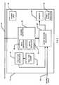
- FIG. 2is a more detailed block diagram of an example of the digital information monitor/analyzer 14 shown in FIG. 1 .
- the digital information monitor/analyzer 14includes a time stamp generator 52 , a real-time clock 54 , an event record generator 56 , and an access detector 58 .
- the access detector 58has a read detector 60 and a write detector 62 associated therewith.
- the event record generator 56receives a source input 63 , which may, for example, be one of the attachments 16 shown in FIG. 1 . Of course, the source input 63 does not necessarily have to be provided by one of the attachment 16 .
- the source input 63may instead be provided by apparatus and techniques that detect a source by analyzing or decoding audio content, video content, etc.
- signature detection systems and methodssystems and methods that insert a tag or other identifier (which are also known), etc. may be used instead.
- the digital information monitor/analyzer 14includes a power unit 64 and may optionally include an event record analyzer 65 and/or a memory 66 that is in communication with the event record generator 56 .
- the real-time clock 54provides information to the time stamp generator 52 that enables the time stamp generator 52 to develop or generate a time stamp including current local date information and time of day information.
- the time stamp generator 52provides time stamps that are used by the event record generator 56 to create event records.
- the access detector 58is in communication with the data bus 26 and monitors the information transmitted thereon to determine when digital information is to be stored on or retrieved from the mass storage device 24 .
- the access detector 58monitors control and command signals present on the data bus 26 to determine if digital information is to be stored and/or recorded on the mass storage device 24 .
- the access detector 58monitors a set of signals commonly associated with the protocol such as the command and control register select signals CS 0 and CS 1 , a set of control register select signals DA 0 , DA 1 and DA 2 , and a lower data bus data byte via signals on set of data lines, DD 0 through DD 7 , to determine whether a read or write operation is in progress and to determine what location on the mass storage device 24 is involved in the read or write operation.
- a set of signals commonly associated with the protocolsuch as the command and control register select signals CS 0 and CS 1 , a set of control register select signals DA 0 , DA 1 and DA 2 , and a lower data bus data byte via signals on set of data lines, DD 0 through DD 7 , to determine whether a read or write operation is in progress and to determine what location on the mass storage device 24 is involved in the read or write operation.
- Table 1an example sequence of signals for an IDE protocol compatible write operation on the data bus 26 is
- the write detector 62can detect a write or record operation to the mass storage device 24 by determining that the value CAH (i.e., CA hexadecimal) is to be stored in a register 1F7 of the disk drive.
- the access detector 58determines the location of the write operation by looking at the values to be stored in a set of registers 1F3 through 1F6.
- the disk drivehas been configured to operate in a logical block addressing (LBA) mode as opposed to a cylinder/head/sector (C:H:S) addressing mode.
- LBAlogical block addressing
- C:H:Scylinder/head/sector
- LBA(cylinder*headcount+headnumber)*sector count+sector number ⁇ 1.
- the access detector 58can also detect the size of the packet of information or data that is to written to the disk drive. In the example shown in Table 1, 256 sectors (i.e., 65,536 bytes) of digital information are to be written to the disk drive. In general, audio, video and/or image information is written in relatively large sets or packets such as, for example, packets containing 65,536 bytes of information. Thus, if desired, the access detector 58 can determine if a packet of digital information to be written to the disk drive or mass storage device 24 contains audio, video and/or image information. In particular, audio, video and/or image information is usually transmitted to the mass storage device 24 in relatively large or maximum size packets (e.g., 65,536 byte packets).
- the access detector 58may be configured to ignore the operation. In this manner, the access detector 58 can be configured to discriminate between different types of content, some of which may be audio, video or image information of interest and some of which may be other information that is not needed by the event record generator 56 . In some examples, such as where web page accesses are monitored, it may not be desirable to ignore any operations or data transfers, regardless of the amount of information contained in the data packets.
- the read detector 60can detect a read or playback operation by determining that the value C8H is to be stored in a register 1F7.
- the access detector 58determines the target location of the read operation by looking at the values to be stored in a set of registers 1F3 through 1F6.
- the event record generator 56is in communication with the access detector 58 and the time stamp generator 52 .
- the event record generator 56generates event records containing time information and storage location information uniquely corresponding to each set or packet of digital information to be written to the mass storage device 24 .
- the event record generator 56receives source information such as, for example, channel information via the source input 63 and includes the source or channel information in each of the event records.
- Table 3 belowprovides two example event records that could be generated in response to two successive write operations, each of which includes a 65,536 byte packet or set of digital information associated with channel 11 , to the mass storage device 24 .
- the 65,536 byte packets associated with the successive write operationswere written to or recorded on the mass storage device 24 one second apart.
- the LBAsare 65,536 bytes apart and are logically successive storage locations on the mass storage device 24 . While the example of Table 3 shows that the successive write operations occurred one second apart, the time between successive write operations could instead be a fraction of a second apart or more than one second apart.
- the speed or ratee.g., the bits per second
- the time between successive write operationsdecreases.
- the maximum record rate limit of the mass storage device 24decreases and as the packet size increases, the time between successive write operations increases.
- the information shown in Table 3may be stored in the memory 66 as a look-up table.
- the look-up tableis used as described in detail below to modify the event record to include a read or playback time, which in the case of digital video information usually corresponds to a viewing time.
- the access detector 58determines that the contents of the storage location 11EF240H are to be read from the mass storage device 24 on Jul. 30, 2002 at 16:30:00 and the contents of the storage location 11EF340H are to be read one second later
- the look-up table stored in the memory 66contains the information shown in Table 4 below.
- the event record generator 56maintains a table or other data structure in the memory 66 that contains a sequence of events record, which enables tracking of read and write operations.
- the read and write operations in a sequence of events recordcorrespond to record and playback operations, respectively.
- a sequence of events recordcan be used to maintain a record of write or record events that is indexed by the storage location on the mass storage device 24 ( FIG. 1 ).
- each storage locatione.g., each logical block address
- there is a corresponding event recordcontaining the time at which the set of data or data packet associated with the write operation was written or recorded on the mass storage device 24 as well as the source or channel from which the audio, video and/or image information within the data packet was originally derived.
- the storage location to be read or played backis used to find the previously stored event record created at the time the information to be read or played back was recorded on the mass storage device 24 .
- the event record analyzer 65may be used to periodically analyze the sequence of events record, which includes all of the write and read events associated with the digital information monitor/analyzer 14 , stored in the memory 66 to ascertain recording and playback habits or behavior associated with those using the digital recording device 12 .
- the digital information monitor/analyzer 14may also generate event records containing information relating to the number and/or identities of those persons involved in the playback event.
- the event record generator 56creates event headers that are stored on the mass storage device 24 along with their respective data packets or sets of digital information. As a result, location information is irrelevant for these examples and, thus, the access detector 58 does not use location information and the event record generator 56 does not store location information on the mass storage device 24 .
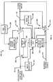
- FIG. 3is a detailed block diagram of another manner of implementing the digital information monitor/analyzer 14 shown in FIG. 1 .
- the digital information monitor/analyzer 14includes a non-volatile memory 102 and a volatile memory 104 in communication with a processor 106 .
- the digital information monitor/analyzer 14includes a real-time clock 108 in communication with the processor 106 and a power management unit 110 .
- the non-volatile memory 102may be a flash memory or any other type of non-volatile memory. Alternatively, the non-volatile memory 102 could be another mass storage device such as, for example, a disk drive.
- the volatile memory 104may be a dynamic random access memory, a static random access memory, or any other suitable type of volatile memory.
- the processor 106may be any type of microprocessor, microcontroller, ASIC, RISC, etc. capable of executing instructions, which are stored in the non-volatile memory 102 and/or the volatile memory 104 , to perform the functions described in connection with the examples of the digital information monitor/analyzer 14 shown in FIGS. 1 and 2 .
- the memories 102 and 104are shown as separate devices they may be integrated within a single device and/or each of the memories 102 and 104 may include multiple memory devices.
- the real-time clock 108enables the processor 106 to calculate current local time information and to generate time stamp information for event records therefrom.
- the power management unit 110enables the processor 106 to copy some or all of the contents of the non-volatile memory 102 to the volatile memory 104 .
- the processor 106stores event records (in response to write operations) and updates or adds playback time information to previously stored event records in response to read operations on the volatile memory 104 .
- the power management unit 110enables the processor 106 to store the contents (including any sequence of events record stored thereon) of the volatile memory 104 on the non-volatile memory 102 . In this manner, the number of write/read cycles that the non-volatile memory 102 is subjected to is greatly reduced. As a consequence, the useful life of the non-volatile memory 102 can be greatly extended because, as is well known, non-volatile memories typically provide a relatively limited number of write/read cycles before failing.
- non-volatile memory 102could be eliminated and a battery could be coupled to the volatile memory 104 to provide continuous power to the volatile memory 104 when external power is not otherwise provided to the digital information monitor/analyzer 14 .
- battery-backed volatile memory configurationsare well known and, thus, are not described in greater detail herein.
- Example programs for implementing the apparatus of FIGS. 2 and 3are shown in FIGS. 4 , 5 , 7 and 14 .
- the programsare for execution by a processor and are embodied in processor instructions stored on a tangible medium such as a CD-ROM, a floppy disk, a hard drive, a digital versatile disk (DVD), or a memory associated with the processor.
- a tangible mediumsuch as a CD-ROM, a floppy disk, a hard drive, a digital versatile disk (DVD), or a memory associated with the processor.
- DVDdigital versatile disk
- persons of ordinary skill in the artwill readily appreciate that the entire program or parts thereof could alternatively be executed by a device other than the processor and/or embodied in firmware or dedicated hardware in a well-known manner.
- any or all of the access detector 58 , the read detector 60 , the write detector 62 , the time stamp generator 52 and/or the event record generator 56could be implemented by any combination of software, hardware and/or firmware.
- the example programsare described with reference to flowcharts, persons of ordinary skill in the art will readily appreciate that many other methods of implementing the apparatus may alternatively be used. For example, the order of execution of the blocks shown in these flowcharts may be changed, and/or some of the blocks described may be changed, eliminated or combined.
- FIG. 4is an example flow diagram illustrating one manner in which the digital video information monitor/analyzer 14 may be configured to generate event records and a sequence of events record.
- the program illustrated in FIG. 4is used with examples of the digital information monitor/analyzer 14 that maintain a sequence of events record using, for example, a look-up table in a memory separate from the mass storage device 24 .
- the program shown in FIG. 4is described as being performed by the example of the digital information monitor/analyzer 14 shown in FIG. 2 .
- the program shown in FIG. 4can be used with other digital information monitor/analyzer devices.
- the write detector 62determines if a large packet is to be stored (i.e., written to, recorded on, etc.) on the mass storage device 24 (block 150 ).
- Digital audio, video and image informationis typically transmitted in relatively large packets.
- video program informationis typically sent to the mass storage device 24 in 65,536 byte packets, whereas user configuration information and other configuration information is usually sent is much smaller packets such as, for example, 512 byte packets.
- the access detector 58determines the location (e.g., the LBA) to which the digital information is to be written or stored (block 152 ) on the mass storage device 24 , determines a current local time (block 154 ) and determines the source (e.g., the channel) associated with the information to be stored or recorded on the mass storage device 24 (block 156 ).
- the event record generator 56then generates an event record containing the current local time and the source information (block 158 ).
- the event record generator 56then stores the event record, preferably in the memory 66 , in the sequence of events record according to the location information (e.g., in a look-up table format indexed by the location information) (block 160 ).
- the read detector 60determines if a large packet of digital information is to be read from the mass storage device 24 (block 162 ).
- a large packet readcorresponds to a playback of digital audio, video and/or image information.
- a packet containing digital audio, video and/or image informationmay be 65,536 bytes, which corresponds to 256 sectors.
- the IDE protocolpermits the use of multiple read/write commands that enable the transmission of packets containing more than 256 sectors of digital information within a single data transaction with a mass storage device.
- the access detector 58determines, based on digital information transmitted on the data bus 26 , the location on the mass storage device 24 from which the packet is to be read (block 164 ).
- the event record generator 56uses the location information to look up the previously stored event record corresponding to that location information in the sequence of events record (i.e., in the look-up table) (block 166 ).
- One particularly useful manner of enabling the event record generator 56 to rapidly look up the event record corresponding to the location information transmitted on the data bus 26establishes a one-to-one correspondence between memory addresses within the memory 66 and the permissible storage locations available within the mass storage device 24 .
- each LBA or C:H:S location on the mass storage device 24may be directly mapped to an address within the memory 66 .
- the time stamp generator 52determines a current local time (e.g., a date and time of day) (block 168 ) and the event record generator 56 adds that current local time information to the event record found at block 166 (block 170 ).
- FIG. 5is a flow diagram of another example manner in which the digital information monitor/analyzer 14 may be configured to generate a sequence of events record.
- the example program shown in FIG. 5is used with examples of the digital information monitor/analyzer 14 that store event records as headers along with digital information on the mass storage device 24 , as opposed to storing event records in a table or other data structure in a memory separate from the mass storage device 24 .
- the write detector 62determines if a large packet is to be written to (i.e., recorded on) the mass storage device 24 (block 200 ). Of course, if desired, a packet size restriction does not have to be implemented. If a large packet is to be written, the time stamp generator 52 determines a current local time (block 202 ), the access detector 58 determines the source of the packet information (block 204 ) and the event record generator 56 generates an event record containing the current local time information and source information (block 206 ).
- a header packetis formed by the event record generator 56 using the event record (block 208 ) and the header packet is prepended or inserted in the data stream of information written to the mass storage device 24 (block 210 ) so that the header packet is stored along with its corresponding data packet on the mass storage device 24 (block 212 ).
- the read detector 60determines if a large packet is to be read from (e.g., played back from) the mass storage device 24 (block 214 ). If a large packet is to be read from the mass storage device 24 , the event record generator 56 determines a current local time (e.g., a date and time of day) (block 216 ), extracts the header packet associated with the packet to be read (block 218 ) and adds the current local time to the extracted header packet to form a playback record (block 220 ). The event record generator 56 then stores the playback record in a sequence of events record, which may contain a plurality of playback records (block 222 ).
- a current local timee.g., a date and time of day
- FIG. 6is a block diagram of an example header packet insertion/extraction apparatus 250 that may be used within the digital information monitor/analyzer 14 to carry out the example method shown in FIG. 5 .
- the header insertion/extraction apparatus 250is serially interposed in the data bus 26 between the local data processing unit 22 and the mass storage device 24 .
- the apparatus 250includes a write detector 252 , a header packet generator 254 , a time stamper 256 , a delay unit 258 , a control unit 260 , a read detector 262 , switches 264 , 266 , 268 and 270 , a playback record output 271 , and an end of packet detector 272 .
- the switches 264 , 266 , 268 and 270are in positions A, A, D and E, respectively.
- the control unitmoves switches 264 and 266 to their respective B positions.
- any digital information transmitted on the bus 26 to the mass storage device 24is delayed by delay unit 258 , which can be implemented using a plurality of shift registers or the like.
- the header packet generator 254generates a header packet containing current local time information derived from the time stamper 256 .
- the header packetmay contain source information generated by one of the attachments 16 ( FIG. 1 ).
- the header packetis then transmitted to the mass storage device 24 on the data bus 26 .
- the control unit 260causes the switch 266 to move to position C, thereby enabling the data packet to be conveyed to and stored on the mass storage device 24 .
- the control unit 260returns the switches 264 and 266 to their respective A positions.
- the control unit 260 and/or read detector 262may be used to detect if a header packet exists. If a header packet exists, the control unit 260 causes the switch 264 to be in its A position, the switch 266 to be in its D position, and the switches 268 and 270 to be in their respective E positions. The previously stored header packet is then routed to the playback record output 271 .
- the end of packet detector 272When the end of packet detector 272 detects the end of the header packet, the end of packet detector 272 sends a signal to the control unit 260 , which, in turn, causes the switch 270 to move to its F position and the switch 266 to move to its A position. With the switch 270 in its F position, the time stamper 256 is enabled to provide current time information via the playback record output 271 . In this manner, the playback record output 271 provides the originally recorded header packet information, which includes the time at which the data packet was written to or stored on the mass storage device 24 , and a read time or playback time for the data packet.
- FIG. 7is a flow diagram of an example manner in which the header packet insertion/extraction apparatus shown in FIG. 6 may be used within the information monitor/analyzer devices shown in FIGS. 1 , 2 and 3 to generate a sequence of events record.
- the digital information monitor/analyzer 14determines if the file size (i.e., the amount of data) associated with a pending data transfer on the data bus 26 is greater than a threshold size associated with an audio, video and/or image file (block 276 ). If the digital information monitor/analyzer 14 determines that the file size exceeds the threshold value, then the write detector 252 determines if a write operation is pending (block 277 ).
- the control unit 260configures the switch 264 to route the file being transferred from the local data processing unit 22 to the mass storage device 24 via the data bus 26 through the delay unit 258 , thereby delaying the audio, video and/or image information or content being sent via the bus 26 (block 278 ).
- the control unit 260sets the switch 266 to its B position to enable the insertion of a header packet on the data bus 26 (block 279 ). Because the audio, video and/or image information or content is delayed, the header packet is sent to the mass storage device 24 immediately ahead of the content information and, thus, is effectively prepended to the content information.
- the prepended or inserted header packetcontains time information generated by the time stamper 256 and may also contain source information and information indicating or otherwise marking the beginning and end of the header packet.
- the control unit 260sets the switch 266 to its C position to enable the delayed audio, video and/or image content information to be conveyed or routed to the mass storage device 24 (block 280 ).
- the read detector 262determines if a read operation is pending on the data bus 26 (block 281 ). If a read operation is pending, the control unit 260 uses the read detector 262 to determine if the beginning of the header packet is being transmitted on the data bus 26 (block 282 ). If the beginning of the header packet is detected (block 282 ), the control unit 260 sets the switches 268 and 270 to their respective E positions to strip the header information from the data bus 26 (i.e., the header information is not routed back to the local data processing unit for display, playback, etc. via a media device such as, for example, a television) (block 283 ).
- the end of packet detector 272determines if the end of the header packet has been transmitted on the data bus 26 (block 284 ). If the end of the header packet has not been detected (block 284 ), then the control unit 260 continues to route or strip the header packet information from the data bus 26 and sends it to the playback record output 271 . On the other hand, if the end of packet detector 272 detects the end of the header packet, the control unit 260 sets the switches 264 and 266 to their A positions, the switch 268 to its D position and the switch 270 to its F position.
- digital audio, video and/or image content associated with the stripped header packetis routed via the data bus 26 to a media device such as, for example, the local data processing unit 22 within a DVR, PVR, etc. (block 285 ).
- the time stamper 256provides time information (e.g., date and time of day information) to the playback record output 271 via the switch 270 , thereby effectively attaching the time information, which in this example, is a playback time, to the header information (block 286 ).
- the playback record output 271may convey the header information, including playback time information, as an event record to a central collection location such as, for example, the data logger/processor 18 (block 287 ).
- FIG. 8is a block diagram of an example system 300 that uses a digital information monitor/analyzer 302 in conjunction with a DVR 304 , such as a TiVoTM system, and an audience measurement unit or home unit 306 .
- the DVR 304includes a video processing unit 308 and a disk drive or hard drive 310 that are coupled via a data bus 312 .
- the disk drive 310is an IDE compatible device and uses a magnetic storage medium having a storage capacity of at least eighty gigabytes. However, the disk drive 310 may optionally use other storage media, have greater or less storage capacity and may communicate with the video processing unit 308 using any desired communication protocol and platform.
- the DVR 304may also include an infrared detector 314 that receives commands and/or other control signals from a hand-held remote control device or another device having an infrared transmitter.
- the DVR 304is in communication with a cable or satellite television signal 316 , to a television 318 and to the digital information monitor/analyzer 302 .
- a source detector 320which may, for example, be a frequency detector attachment, is in communication with the digital information monitor/analyzer 302 and provides tuning information thereto.
- the digital information monitor/analyzer 302may optionally include an infrared transmitter 322 that enables the digital information monitor/analyzer 302 to communicate with the DVR 304 via its infrared detector 314 .
- the digital information monitor/analyzer 302may be configured identically or similarly to any of the examples of the digital information monitor/analyzer 14 shown and described in connection with FIGS. 1 , 2 and 3 .
- the digital information monitor/analyzer 302monitors the data bus 312 and generates event records containing recording times and sources and, if needed by the digital information monitor/analyzer 302 , the storage locations of those event records on the disk drive 310 .
- the digital information monitor/analyzer 302adds read time, playback time or viewing time information to the event records to generate a sequence of events record that can be further analyzed, as described in greater detail below, by the digital information monitor/analyzer 302 , the home unit 306 and/or a central data processing facility such as the facility 20 shown in FIG. 1 to ascertain audience viewing behaviors or habits.
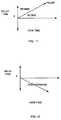
- FIGS. 9 through 12Before discussing a specific example of an analysis of a sequence of events record generated by the digital information monitor/analyzer 302 , a discussion of the general relationships between the various operational modes of the DVR 304 and the characteristics of a sequence of events record is provided in connection with FIGS. 9 through 12 below.
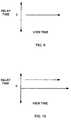
- the horizontal axisrepresents the view time or playback time associated with the event records and the vertical axis represents the delay time (i.e., the difference between the playback or viewing time and the record time).
- FIG. 9is a graph that depicts an example of live viewing of a video program via the DVR 304 .
- the delay timeequals zero for all view times during live viewing of a program.
- FIG. 10is a graph that depicts an example of delayed viewing of video program via the DVR 304 .
- the delay timeis constant for all view times, indicating that a part of or the entire video program currently being viewed was previously recorded by the DVR 304 and is now being viewed.
- FIG. 11is a graph that depicts an example relationship between view time and delay time for pause and rewind operations of the DVR 304 .
- a pauseresults in a one-for-one increase in delay time and view time and, thus, the line having a slope equal to one (i.e., at forty-five degrees) represents a paused condition of the DVR 304 .
- the relationship between view time and delay timefalls between the forty-five degree pause line and the vertical axis at ninety degrees, a rewind operation of the DVR 304 is indicated.
- FIG. 12is a graph that depicts an example relationship between view time and delay time for a fast forward operation of the DVR 304 .
- the delay timedecreases as the view time increases.
- FIG. 12if the relationship between view time and delay time falls between the positive portion of the horizontal axis and the negative portion of the vertical axis (i.e., at minus ninety degrees), a fast forward operation of the DVR 304 is indicated.
- FIG. 13is a graph of an example viewing behavior associated with the DVR 304 .
- the example graph shown in FIG. 13may be generated based on a sequence of events record by the digital information monitor/analyzer 302 and/or by the home unit 306 .
- the example viewing behavior information graphically depicted in FIG. 13could instead be generated by a central data processing facility in communication with the home unit 306 .
- the viewing behavior associated with the DVR 304can be interpreted in light of the general operational characteristics of the DVR 304 shown in FIGS. 9-12 .
- the delay timeequals zero for all view times and, thus, indicates that live viewing of a viewer interface menu or a video program is occurring.
- second and third regions 402 and 404a time shift occurs, indicating that a “go back” command or the like may have been issued by the viewer (via a hand-held remote control or the like) to the DVR 304 , causing the DVR to rewind and then resume delayed playback of a video program.
- the slopeequals one, indicating that the DVR 304 is paused.
- the DVR 304resumes delayed playback of the video program.
- the slope of the characteristicis negative, indicating that a fast forward operation is in progress.
- the DVR 304resumes delayed playback.
- the slope of the characteristicis greater than one (i.e., greater than forty-five degrees), indicating that the DVR 304 is engaged in a rewind operation.
- the DVRresumes delayed playback.
- the time delayis again zero for all view times and, thus, the DVR 304 is operating to provide live viewing of a video program.
- DVR 304 shown in FIG. 8it may not be possible in some circumstances to distinguish live viewing of a program from paused operation of the DVR 304 by only monitoring information transmitted on the data bus 312 .
- informationmay in some cases only be written (i.e., there are no read operations) to the disk drive 310 .
- informationmay, in some cases, only be written to the disk drive 310 .
- the last viewed video framedoes not have to be read from the disk drive 310 because a refresh circuit (not shown) within the DVR 310 is used to constantly regenerate the last frame and provide it to the television 318 . Consequently, in some circumstances live viewing and paused operation will appear to be identical based on the information monitored on the data bus 312 .
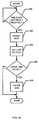
- FIG. 14is a flow diagram of an example program that can be used by the digital information monitor/analyzer 14 described herein to eliminate the possibility that paused operation and live viewing operation of a DVR cannot be distinguished.
- the digital information monitor/analyzer 14determines if the elapsed time since a last read of the disk drive 310 is greater than a predetermined threshold time (e.g., several seconds) (block 500 ). If the elapsed time is not greater than the predetermined threshold time (block 500 ), the digital information monitor/analyzer 14 reenters block 500 .
- a predetermined threshold timee.g., several seconds
- the digital information monitor/analyzer 14causes the DVR 304 to pause for a brief time such as, for example, about one-half of a second (block 502 ). The digital information monitor/analyzer 14 then causes the DVR 304 to enter playback operation (block 504 ).
- the digital information monitor/analyzer 14determines if there has been a time delay (block 506 ) greater than a second threshold.
- a time delay exceeding the second thresholde.g., more than one second
- the digital information monitor/analyzer 14causes the DVR 304 to enter paused operation (block 508 ).
- the digital information monitor/analyzer 14determines that the time delay (block 506 ), if any, does not exceed the second threshold, then the DVR 304 is allowed to remain in a playback operating mode.
- the various DVR commands required to carry out the example method shown in FIG. 14can be transmitted to the DVR 304 by the digital information monitor/analyzer 14 via the infrared transmitter 322 and the infrared detector 314 .
Landscapes
- Engineering & Computer Science (AREA)
- Signal Processing (AREA)
- Health & Medical Sciences (AREA)
- General Health & Medical Sciences (AREA)
- Social Psychology (AREA)
- Multimedia (AREA)
- Signal Processing For Digital Recording And Reproducing (AREA)
- Television Signal Processing For Recording (AREA)
Abstract
Description
| TABLE 1 |
| WRITE 65,536 BYTES OF DATA TO DRIVE |
| Register | Data Low | Action/ | |||||
| DA2 | DA1 | DA0 | Addressed | (DD7-DD0) | |||
| 0 | 1 | 1 | 1 | 0 | 3F6 | 08H | Enable |
| interrupts | |||||||
| 1 | 0 | 0 | 1 | 0 | 1F2 | 00H | Sectors = |
| 256 | |||||||
| 1 | 0 | 0 | 1 | 1 | 1F3 | 40H | LBA = |
| 1 | 0 | 1 | 0 | 0 | 1F4 | F2H | 11EF240H |
| 1 | 0 | 1 | 0 | 1 | 1F5 | 1EH | |
| 1 | 0 | 1 | 1 | 0 | 1F6 | E1H | |
| 1 | 0 | 1 | 1 | 1 | 1F7 | CAH | Write to |
| drive | |||||||
| TABLE 2 |
| READ 65,536 BYTES OF DATA FROM DRIVE |
| Register | Data Low | Action/ | |||||
| DA2 | DA1 | DA0 | Addressed | (DD7-DD0) | |||
| 0 | 1 | 1 | 1 | 0 | 3F6 | 08H | Enable |
| interrupts | |||||||
| 1 | 0 | 0 | 1 | 0 | 1F2 | 00H | Sectors = |
| 256 | |||||||
| 1 | 0 | 0 | 1 | 1 | 1F3 | 40H | LBA = |
| 1 | 0 | 1 | 0 | 0 | 1F4 | F2H | 11EF240H |
| 1 | 0 | 1 | 0 | 1 | 1F5 | 1EH | |
| 1 | 0 | 1 | 1 | 0 | 1F6 | E1H | |
| 1 | 0 | 1 | 1 | 1 | 1F7 | C8H | Read from |
| drive | |||||||
| TABLE 3 | |||
| Storage location | Event Record Generated | ||
| (LBA) | (date, time of day, source) | ||
| 11EF240H | 07/30/02 16:05:31 011 | ||
| 11EF340H | 07/30/02 16:05:32 011 | ||
| TABLE 4 | ||
| Storage location | Event Record Generated | Playback Time |
| (LBA) | (date, time of day, source) | (Read Time) |
| 11EF240H | 07/30/02 16:05:31 011 | 07/30/02 16:30:00 |
| 11EF340H | 07/30/02 16:05:32 011 | 07/30/02 16:30:01 |
Claims (26)
Priority Applications (2)
| Application Number | Priority Date | Filing Date | Title |
|---|---|---|---|
| US11/138,576US8204353B2 (en) | 2002-11-27 | 2005-05-26 | Apparatus and methods for tracking and analyzing digital recording device event sequences |
| US12/144,915US9991980B2 (en) | 2002-11-27 | 2008-06-24 | Apparatus and methods for tracking and analyzing digital recording device event sequences |
Applications Claiming Priority (2)
| Application Number | Priority Date | Filing Date | Title |
|---|---|---|---|
| PCT/US2002/038012WO2004051997A1 (en) | 2002-11-27 | 2002-11-27 | Apparatus and methods for tracking and analyzing digital recording device event sequences |
| US11/138,576US8204353B2 (en) | 2002-11-27 | 2005-05-26 | Apparatus and methods for tracking and analyzing digital recording device event sequences |
Related Parent Applications (1)
| Application Number | Title | Priority Date | Filing Date |
|---|---|---|---|
| PCT/US2002/038012ContinuationWO2004051997A1 (en) | 2002-11-27 | 2002-11-27 | Apparatus and methods for tracking and analyzing digital recording device event sequences |
Related Child Applications (1)
| Application Number | Title | Priority Date | Filing Date |
|---|---|---|---|
| US12/144,915ContinuationUS9991980B2 (en) | 2002-11-27 | 2008-06-24 | Apparatus and methods for tracking and analyzing digital recording device event sequences |
Publications (2)
| Publication Number | Publication Date |
|---|---|
| US20050286860A1 US20050286860A1 (en) | 2005-12-29 |
| US8204353B2true US8204353B2 (en) | 2012-06-19 |
Family
ID=35505852
Family Applications (2)
| Application Number | Title | Priority Date | Filing Date |
|---|---|---|---|
| US11/138,576Expired - Fee RelatedUS8204353B2 (en) | 2002-11-27 | 2005-05-26 | Apparatus and methods for tracking and analyzing digital recording device event sequences |
| US12/144,915Active2026-08-19US9991980B2 (en) | 2002-11-27 | 2008-06-24 | Apparatus and methods for tracking and analyzing digital recording device event sequences |
Family Applications After (1)
| Application Number | Title | Priority Date | Filing Date |
|---|---|---|---|
| US12/144,915Active2026-08-19US9991980B2 (en) | 2002-11-27 | 2008-06-24 | Apparatus and methods for tracking and analyzing digital recording device event sequences |
Country Status (1)
| Country | Link |
|---|---|
| US (2) | US8204353B2 (en) |
Cited By (1)
| Publication number | Priority date | Publication date | Assignee | Title |
|---|---|---|---|---|
| US8869187B2 (en) | 2004-02-17 | 2014-10-21 | The Nielsen Company (Us), Llc | Methods and apparatus to determine audience viewing of recorded programs |
Families Citing this family (43)
| Publication number | Priority date | Publication date | Assignee | Title |
|---|---|---|---|---|
| US8574074B2 (en) | 2005-09-30 | 2013-11-05 | Sony Computer Entertainment America Llc | Advertising impression determination |
| US8751310B2 (en) | 2005-09-30 | 2014-06-10 | Sony Computer Entertainment America Llc | Monitoring advertisement impressions |
| US7786987B2 (en) | 2003-09-25 | 2010-08-31 | The Nielsen Company (Us), Llc | Methods and apparatus to detect an operating state of a display based on visible light |
| US9027043B2 (en) | 2003-09-25 | 2015-05-05 | The Nielsen Company (Us), Llc | Methods and apparatus to detect an operating state of a display |
| JP4398777B2 (en)* | 2004-04-28 | 2010-01-13 | 株式会社東芝 | Time series data analysis apparatus and method |
| EP1790152A4 (en) | 2004-08-09 | 2008-10-08 | Nielsen Media Res Inc | Methods and apparatus to monitor audio/visual content from various sources |
| US8763157B2 (en) | 2004-08-23 | 2014-06-24 | Sony Computer Entertainment America Llc | Statutory license restricted digital media playback on portable devices |
| WO2007022250A2 (en) | 2005-08-16 | 2007-02-22 | Nielsen Media Research, Inc. | Display device on/off detection methods and apparatus |
| US20070118425A1 (en) | 2005-10-25 | 2007-05-24 | Podbridge, Inc. | User device agent for asynchronous advertising in time and space shifted media network |
| US20070094083A1 (en)* | 2005-10-25 | 2007-04-26 | Podbridge, Inc. | Matching ads to content and users for time and space shifted media network |
| US20070094363A1 (en)* | 2005-10-25 | 2007-04-26 | Podbridge, Inc. | Configuration for ad and content delivery in time and space shifted media network |
| US10657538B2 (en) | 2005-10-25 | 2020-05-19 | Sony Interactive Entertainment LLC | Resolution of advertising rules |
| US11004089B2 (en) | 2005-10-25 | 2021-05-11 | Sony Interactive Entertainment LLC | Associating media content files with advertisements |
| US8676900B2 (en) | 2005-10-25 | 2014-03-18 | Sony Computer Entertainment America Llc | Asynchronous advertising placement based on metadata |
| EP2018728A4 (en) | 2006-05-05 | 2011-07-06 | Sony Comp Entertainment Us | Advertisement rotation |
| US20080098436A1 (en)* | 2006-10-19 | 2008-04-24 | Sbc Knowledge Ventures, L.P. | Top recording events list for media device |
| US8056101B2 (en)* | 2006-11-02 | 2011-11-08 | At&T Intellectual Property I, L.P. | Customized interface based on viewed programming |
| JP5040292B2 (en) | 2006-12-19 | 2012-10-03 | ソニー株式会社 | Information processing apparatus, information processing method, and program |
| US8516515B2 (en)* | 2007-04-03 | 2013-08-20 | Google Inc. | Impression based television advertising |
| US7743394B2 (en) | 2007-04-03 | 2010-06-22 | Google Inc. | Log processing of channel tunes and channel tune times generated from a television processing device |
| US8769558B2 (en) | 2008-02-12 | 2014-07-01 | Sony Computer Entertainment America Llc | Discovery and analytics for episodic downloaded media |
| US8180712B2 (en) | 2008-09-30 | 2012-05-15 | The Nielsen Company (Us), Llc | Methods and apparatus for determining whether a media presentation device is in an on state or an off state |
| US8793717B2 (en) | 2008-10-31 | 2014-07-29 | The Nielsen Company (Us), Llc | Probabilistic methods and apparatus to determine the state of a media device |
| US8375404B2 (en) | 2008-12-30 | 2013-02-12 | The Nielsen Company (Us), Llc | Methods and apparatus to enforce a power off state of an audience measurement device during shipping |
| US8156517B2 (en) | 2008-12-30 | 2012-04-10 | The Nielsen Company (U.S.), Llc | Methods and apparatus to enforce a power off state of an audience measurement device during shipping |
| US8255949B1 (en) | 2009-01-07 | 2012-08-28 | Google Inc. | Television program targeting for advertising |
| US8763090B2 (en) | 2009-08-11 | 2014-06-24 | Sony Computer Entertainment America Llc | Management of ancillary content delivery and presentation |
| US8605209B2 (en) | 2009-11-24 | 2013-12-10 | Gregory Towle Becker | Hurricane damage recording camera system |
| US8677385B2 (en) | 2010-09-21 | 2014-03-18 | The Nielsen Company (Us), Llc | Methods, apparatus, and systems to collect audience measurement data |
| US10089592B2 (en) | 2010-12-29 | 2018-10-02 | Comcast Cable Communications, Llc | Measuring video asset viewing |
| US12271855B2 (en) | 2010-12-29 | 2025-04-08 | Comcast Cable Communications, Llc | Measuring video-asset viewing |
| US10945011B2 (en) | 2010-12-29 | 2021-03-09 | Comcast Cable Communications, Llc | Measuring video viewing |
| US8365212B1 (en) | 2010-12-29 | 2013-01-29 | Robert Alan Orlowski | System and method for analyzing human interaction with electronic devices that access a computer system through a network |
| US9473795B2 (en) | 2011-12-19 | 2016-10-18 | The Nielsen Company (Us), Llc | Methods and apparatus for crediting a media presentation device |
| US10645433B1 (en) | 2013-08-29 | 2020-05-05 | Comcast Cable Communications, Llc | Measuring video-content viewing |
| US12200298B2 (en) | 2013-09-06 | 2025-01-14 | Comcast Cable Communications, Llc | Measuring video-program viewing |
| US11627356B2 (en) | 2012-01-28 | 2023-04-11 | Comcast Cable Communications, Llc | Data translation for video-viewing activity |
| US10440428B2 (en) | 2013-01-13 | 2019-10-08 | Comcast Cable Communications, Llc | Measuring video-program-viewing activity |
| US9692535B2 (en) | 2012-02-20 | 2017-06-27 | The Nielsen Company (Us), Llc | Methods and apparatus for automatic TV on/off detection |
| WO2014174738A1 (en)* | 2013-04-26 | 2014-10-30 | 日本電気株式会社 | Monitoring device, monitoring method and monitoring program |
| US20160295276A1 (en)* | 2015-04-02 | 2016-10-06 | Qdos, Inc. D/B/A Desksite | Method and system for localized day parting when presenting a second video with one or more first videos |
| US9924224B2 (en) | 2015-04-03 | 2018-03-20 | The Nielsen Company (Us), Llc | Methods and apparatus to determine a state of a media presentation device |
| US10045082B2 (en) | 2015-07-02 | 2018-08-07 | The Nielsen Company (Us), Llc | Methods and apparatus to correct errors in audience measurements for media accessed using over-the-top devices |
Citations (108)
| Publication number | Priority date | Publication date | Assignee | Title |
|---|---|---|---|---|
| US4361832A (en) | 1977-01-28 | 1982-11-30 | Cole Martin T | Automatic centralized monitoring system |
| US4367525A (en) | 1980-06-06 | 1983-01-04 | Tesdata Systems Corporation | CPU Channel monitoring system |
| US4455634A (en) | 1982-01-12 | 1984-06-19 | Discovision Associates | Audio/video quality monitoring system |
| US4566030A (en) | 1983-06-09 | 1986-01-21 | Ctba Associates | Television viewer data collection system |
| US4697209A (en) | 1984-04-26 | 1987-09-29 | A. C. Nielsen Company | Methods and apparatus for automatically identifying programs viewed or recorded |
| US4792864A (en) | 1985-09-03 | 1988-12-20 | Video Research Limited | Apparatus for detecting recorded data in a video tape recorder for audience rating purposes |
| US4885632A (en) | 1988-02-29 | 1989-12-05 | Agb Television Research | System and methods for monitoring TV viewing system including a VCR and/or a cable converter |
| US5034902A (en) | 1986-12-09 | 1991-07-23 | Srg Schweizerische Radio-Und Fernsehgesellschaft | Method and system for ascertaining the consumption habits of a test population |
| US5165069A (en) | 1990-07-30 | 1992-11-17 | A. C. Nielsen Company | Method and system for non-invasively identifying the operational status of a VCR |
| WO1994011989A1 (en) | 1992-11-16 | 1994-05-26 | The Arbitron Company | Method and apparatus for encoding/decoding broadcast or recorded segments and monitoring audience exposure thereto |
| US5319453A (en) | 1989-06-22 | 1994-06-07 | Airtrax | Method and apparatus for video signal encoding, decoding and monitoring |
| US5373315A (en) | 1991-04-25 | 1994-12-13 | Le Groupe Videotron Ltee | Television audience data gathering |
| WO1995004430A1 (en) | 1993-08-02 | 1995-02-09 | The Arbitron Company | Compliance incentives for audience monitoring/recording devices |
| WO1995012278A1 (en) | 1993-10-27 | 1995-05-04 | A.C. Nielsen Company | Audience measurement system |
| US5425100A (en) | 1992-11-25 | 1995-06-13 | A.C. Nielsen Company | Universal broadcast code and multi-level encoded signal monitoring system |
| US5436653A (en) | 1992-04-30 | 1995-07-25 | The Arbitron Company | Method and system for recognition of broadcast segments |
| US5438355A (en) | 1993-04-16 | 1995-08-01 | Palmer; Shelton L. | Interactive system for processing viewer responses to television programming |
| US5457694A (en) | 1993-06-25 | 1995-10-10 | Smith; Dale J. | Method and apparatus for analyzing the ATA (IDE) interface |
| WO1995035606A1 (en) | 1994-06-21 | 1995-12-28 | Steven Bradford Greene | System for collecting data concerning received transmitted material |
| US5481296A (en) | 1993-08-06 | 1996-01-02 | International Business Machines Corporation | Apparatus and method for selectively viewing video information |
| US5488409A (en) | 1991-08-19 | 1996-01-30 | Yuen; Henry C. | Apparatus and method for tracking the playing of VCR programs |
| US5488408A (en) | 1994-03-22 | 1996-01-30 | A.C. Nielsen Company | Serial data channel metering attachment for metering channels to which a receiver is tuned |
| US5532732A (en) | 1988-12-23 | 1996-07-02 | Gemstar Development Corporation | Apparatus and methods for using compressed codes for monitoring television program viewing |
| WO1996027840A1 (en) | 1995-03-04 | 1996-09-12 | Televitesse Systems Inc. | Automatic broadcast monitoring system |
| US5608866A (en) | 1994-04-08 | 1997-03-04 | Nec Corporation | System for measuring and analyzing operation of information processor |
| US5734720A (en) | 1994-11-29 | 1998-03-31 | Salganicoff; Marcos | System and method for providing digital communications between a head end and a set top terminal |
| US5844478A (en) | 1996-05-31 | 1998-12-01 | Thomson Consumer Electronics, Inc. | Program specific information formation for digital data processing |
| US5848046A (en)* | 1996-08-05 | 1998-12-08 | Fujitsu Limited | Disk apparatus having signal processing unit |
| WO1998057267A1 (en) | 1997-06-11 | 1998-12-17 | Sun Microsystems, Inc. | Computer system employing a bus snooping multimedia subsystem for implementing video multicast transactions |
| US5867205A (en) | 1994-11-14 | 1999-02-02 | Intel Corporation | Method and apparatus for controlling video/audio and channel selection for a communication signal based on textual information indicative of channel contents of a signal |
| US5872588A (en) | 1995-12-06 | 1999-02-16 | International Business Machines Corporation | Method and apparatus for monitoring audio-visual materials presented to a subscriber |
| US5892536A (en) | 1996-10-03 | 1999-04-06 | Personal Audio | Systems and methods for computer enhanced broadcast monitoring |
| US5986692A (en) | 1996-10-03 | 1999-11-16 | Logan; James D. | Systems and methods for computer enhanced broadcast monitoring |
| WO2000011865A1 (en) | 1998-08-21 | 2000-03-02 | Sony Electronics, Inc. | A method and system to collect information |
| US6061056A (en) | 1996-03-04 | 2000-05-09 | Telexis Corporation | Television monitoring system with automatic selection of program material of interest and subsequent display under user control |
| US6184918B1 (en) | 1997-09-30 | 2001-02-06 | Intel Corporation | Method and apparatus for monitoring viewing of broadcast data |
| US6216265B1 (en) | 1990-09-10 | 2001-04-10 | Starsight Telecast, Inc. | System and method for transmitting and utilizing electronic program guide information |
| US6233389B1 (en) | 1998-07-30 | 2001-05-15 | Tivo, Inc. | Multimedia time warping system |
| EP1100265A1 (en) | 1999-04-26 | 2001-05-16 | Sony Corporation | Information processing device and method for controlling programmed video recording of television broadcast program and recorded medium on which program is recorded |
| US6253238B1 (en) | 1998-12-02 | 2001-06-26 | Ictv, Inc. | Interactive cable television system with frame grabber |
| US6286140B1 (en) | 1997-11-20 | 2001-09-04 | Thomas P. Ivanyi | System and method for measuring and storing information pertaining to television viewer or user behavior |
| US20010023436A1 (en) | 1998-09-16 | 2001-09-20 | Anand Srinivasan | Method and apparatus for multiplexing seperately-authored metadata for insertion into a video data stream |
| US20020007416A1 (en) | 1998-06-23 | 2002-01-17 | David M. Putzolu | Recognizing audio and video streams over ppp links in the absence of an announcement protocol |
| US20020010921A1 (en) | 1997-06-12 | 2002-01-24 | Toru Kambayashi | Method and apparatus of displaying bit stream data, method and apparatus for generating bit stream data, and storage medium |
| US20020010919A1 (en) | 1998-05-12 | 2002-01-24 | Nielsen Media Research, Inc. | Audience measurement system for digital television |
| US20020056089A1 (en) | 1997-06-23 | 2002-05-09 | Houston John S. | Cooperative system for measuring electronic media |
| US20020056087A1 (en) | 2000-03-31 | 2002-05-09 | Berezowski David M. | Systems and methods for improved audience measuring |
| US20020059637A1 (en) | 2000-01-14 | 2002-05-16 | Rakib Selim Shlomo | Home gateway for video and data distribution from various types of headend facilities and including digital video recording functions |
| US20020059576A1 (en) | 1998-12-08 | 2002-05-16 | Feininger William A. | Metering viewing of video displayed in windows |
| US20020059643A1 (en) | 1999-12-03 | 2002-05-16 | Takuya Kitamura | Information processing apparatus, information processing method and recording medium |
| US20020069218A1 (en) | 2000-07-24 | 2002-06-06 | Sanghoon Sull | System and method for indexing, searching, identifying, and editing portions of electronic multimedia files |
| US6405275B1 (en) | 1998-06-15 | 2002-06-11 | Texas Instruments Incorporated | IEEE1394 common isochronous packet (CIP) enhancements for host controllers |
| US20020078441A1 (en) | 2000-08-31 | 2002-06-20 | Eddie Drake | Real-time audience monitoring, content rating, and content enhancing |
| US20020124246A1 (en) | 2001-03-02 | 2002-09-05 | Kaminsky David Louis | Methods, systems and program products for tracking information distribution |
| US6457010B1 (en) | 1998-12-03 | 2002-09-24 | Expanse Networks, Inc. | Client-server based subscriber characterization system |
| US6460018B1 (en)* | 1997-03-31 | 2002-10-01 | Sony Corporation | Program production and transmission apparatus |
| US20020141730A1 (en) | 2001-03-27 | 2002-10-03 | Koninklijke Philips Electronics N.V. | TV recorder with inoperative settop box functions |
| US20020162115A1 (en) | 2001-04-25 | 2002-10-31 | Bruckner John Anthony | System and method for monitoring and recovering the state of user participation in interactive broadcasts |
| US20020173911A1 (en) | 2001-05-07 | 2002-11-21 | Xavier Brunet | Database indexing and rolling storage method for time-stamped normalized event data |
| US20020178277A1 (en) | 2001-05-24 | 2002-11-28 | Indra Laksono | Method and apparatus for multimedia system |
| US20030005432A1 (en) | 2000-11-28 | 2003-01-02 | Ellis Michael D. | Interactive television application with research features |
| US6513161B2 (en) | 1997-01-22 | 2003-01-28 | Nielsen Media Research, Inc. | Monitoring system for recording device |
| US20030037333A1 (en) | 1999-03-30 | 2003-02-20 | John Ghashghai | Audience measurement system |
| US20030039464A1 (en) | 2001-07-05 | 2003-02-27 | Davis Bruce L. | Watermarking to control video recording |
| US6529506B1 (en) | 1998-10-08 | 2003-03-04 | Matsushita Electric Industrial Co., Ltd. | Data processing apparatus and data recording media |
| US6530082B1 (en) | 1998-04-30 | 2003-03-04 | Wink Communications, Inc. | Configurable monitoring of program viewership and usage of interactive applications |
| US20030067554A1 (en) | 2000-09-25 | 2003-04-10 | Klarfeld Kenneth A. | System and method for personalized TV |
| US20030072556A1 (en) | 2001-09-21 | 2003-04-17 | Kunihiro Okujima | Apparatus, method, program and recording medium for program recording and reproducing |
| US20030093790A1 (en) | 2000-03-28 | 2003-05-15 | Logan James D. | Audio and video program recording, editing and playback systems using metadata |
| US6567978B1 (en) | 1998-10-09 | 2003-05-20 | Adcom Information Services, Inc. | Television audience monitoring system and method employing display of cable converter box |
| US20030115587A1 (en) | 2001-12-18 | 2003-06-19 | Kendall Scott Allan | Method and apparatus for generating commercial viewing/listening information |
| US20030172376A1 (en) | 2002-03-11 | 2003-09-11 | Microsoft Corporation | User controlled targeted advertisement placement for receiver modules |
| US20030170001A1 (en) | 2002-03-07 | 2003-09-11 | Breen Julian H. | Method and apparatus for monitoring audio listening |
| US20030177488A1 (en) | 2002-03-12 | 2003-09-18 | Smith Geoff S. | Systems and methods for media audience measurement |
| US20030182567A1 (en) | 1999-10-20 | 2003-09-25 | Tivo Inc. | Client-side multimedia content targeting system |
| US20030192060A1 (en) | 2001-01-30 | 2003-10-09 | Levy Kenneth L. | Digital watermarking and television services |
| US20040010807A1 (en) | 2002-05-03 | 2004-01-15 | Urdang Erik G. | Use of multiple embedded messages in program signal streams |
| US6681285B1 (en) | 1999-07-22 | 2004-01-20 | Index Systems, Inc. | Memory controller and interface |
| US20040025174A1 (en) | 2002-05-31 | 2004-02-05 | Predictive Media Corporation | Method and system for the storage, viewing management, and delivery of targeted advertising |
| US20040031045A1 (en) | 1997-11-20 | 2004-02-12 | Ivanyi Thomas P. | System and method for measuring and storing information pertaining to television viewer or user behavior |
| US6704929B1 (en) | 1999-08-18 | 2004-03-09 | Webtv Networks, Inc. | Tracking viewing behavior of a home entertainment system |
| US6717917B1 (en) | 2000-06-09 | 2004-04-06 | Ixia | Method of determining real-time data latency and apparatus therefor |
| US6725342B1 (en)* | 2000-09-26 | 2004-04-20 | Intel Corporation | Non-volatile mass storage cache coherency apparatus |
| CA2507317A1 (en) | 2002-11-27 | 2004-06-17 | Nielsen Media Research, Inc. | Apparatus and methods for tracking and analyzing digital recording device event sequences |
| US20040250281A1 (en) | 2003-04-17 | 2004-12-09 | Feininger William A. | Methods and apparatus to detect content skipping by a consumer of a recorded program |
| US20050054285A1 (en) | 2003-02-10 | 2005-03-10 | Mears Paul M. | Methods and apparatus to adaptively gather audience information data |
| US20050076358A1 (en) | 2003-09-01 | 2005-04-07 | Nec Corporation | Apparatus, system, and method for measuring data broadcast viewing information |
| WO2005036877A1 (en) | 2003-09-12 | 2005-04-21 | Nielsen Media Research, Inc. | Digital video signature apparatus and methods for use with video program identification systems |
| US20050138659A1 (en) | 2003-12-17 | 2005-06-23 | Gilles Boccon-Gibod | Personal video recorders with automated buffering |
| WO2005079941A1 (en) | 2004-02-17 | 2005-09-01 | Nielsen Media Research, Inc. Et Al. | Methods and apparatus for monitoring video games |
| WO2005079457A2 (en) | 2004-02-17 | 2005-09-01 | Nielsen Media Research, Inc. Et Al. | Methods and apparatus to determine audience viewing of recorded programs |
| US20050193414A1 (en)* | 2001-04-04 | 2005-09-01 | Microsoft Corporation | Training, inference and user interface for guiding the caching of media content on local stores |
| WO2005084186A2 (en) | 2004-02-23 | 2005-09-15 | Nielsen Media Research, Inc. | Methods and apparatus to detect an internally generated signal mode of a local media playback device |
| US20050232411A1 (en) | 1999-10-27 | 2005-10-20 | Venugopal Srinivasan | Audio signature extraction and correlation |
| WO2005114450A1 (en) | 2004-05-14 | 2005-12-01 | Nielsen Media Research, Inc. | Methods and apparatus for identifying media content |
| WO2005124583A1 (en) | 2004-06-08 | 2005-12-29 | Nielsen Media Research, Inc. | Methods and apparatus to verify consumption of programming content |
| WO2005125198A2 (en) | 2004-06-09 | 2005-12-29 | Nielsen Media Research, Inc. | Methods and apparatus to identify viewing information |
| US20060015902A1 (en) | 2002-11-14 | 2006-01-19 | Matsushita Electric Industrial Co., Ltd. | Viewing history recording method and viewing history use method |
| WO2006012629A2 (en) | 2004-07-23 | 2006-02-02 | Nielsen Media Research, Inc. | Methods and apparatus for monitoring the insertion of local media content into a program stream |
| WO2006014495A1 (en) | 2004-07-02 | 2006-02-09 | Nielsen Media Research, Inc. | Methods and apparatus for identifying viewing information associated with a digital media device |
| US20060085812A1 (en) | 2004-10-15 | 2006-04-20 | Shishegar Ahmad R | Method for monitoring television usage |
| US20060184961A1 (en) | 2003-06-20 | 2006-08-17 | Nielsen Media Research, Inc. | Signature-based program identification apparatus and methods for use with digital broadcast systems |
| WO2006055897A3 (en) | 2004-11-19 | 2006-11-16 | Nielsen Media Res Inc | Method for detecting space-shifted media |
| US20070006250A1 (en) | 2004-01-14 | 2007-01-04 | Croy David J | Portable audience measurement architectures and methods for portable audience measurement |
| WO2005107110A3 (en) | 2004-04-23 | 2007-04-19 | Nielsen Media Res Inc | Methods and apparatus to maintain audience privacy while determining viewing of video-on-demand programs |
| WO2006020560A3 (en) | 2004-08-09 | 2007-05-03 | Nielsen Media Res Inc | Methods and apparatus to monitor audio/visual content from various sources |
| US7286667B1 (en) | 2003-09-15 | 2007-10-23 | Sony Corporation | Decryption system |
| US20100247065A1 (en)* | 1994-10-12 | 2010-09-30 | Pixel Instruments Corporation | Program viewing apparatus and method |
Family Cites Families (14)
| Publication number | Priority date | Publication date | Assignee | Title |
|---|---|---|---|---|
| US584046A (en)* | 1897-06-08 | Centrifugal machine | ||
| US6611537B1 (en) | 1997-05-30 | 2003-08-26 | Centillium Communications, Inc. | Synchronous network for digital media streams |
| US6614987B1 (en)* | 1998-06-12 | 2003-09-02 | Metabyte, Inc. | Television program recording with user preference determination |
| US6202103B1 (en)* | 1998-11-23 | 2001-03-13 | 3A International, Inc. | Bus data analyzer including a modular bus interface |
| CN1265386C (en) | 1999-03-30 | 2006-07-19 | 提维股份有限公司 | System for automatic playback position correction after fast forward or reverse |
| WO2000058967A1 (en) | 1999-03-30 | 2000-10-05 | Tivo, Inc. | Multimedia program bookmarking system |
| CN100379273C (en) | 1999-09-20 | 2008-04-02 | 提维股份有限公司 | Closed caption tagging system |
| US7085995B2 (en)* | 2000-01-26 | 2006-08-01 | Sony Corporation | Information processing apparatus and processing method and program storage medium |
| CA2400210A1 (en) | 2000-02-18 | 2001-08-23 | Ac Nielsen Corporation | Audience measurement system and method for digital broadcasts |
| US6934508B2 (en) | 2001-03-19 | 2005-08-23 | Navigaug Inc. | System and method for obtaining comprehensive vehicle radio listener statistics |
| JP4326174B2 (en)* | 2001-10-04 | 2009-09-02 | ソニー株式会社 | Information processing system, information processing apparatus and method, recording medium, and program |
| US9967633B1 (en) | 2001-12-14 | 2018-05-08 | At&T Intellectual Property I, L.P. | System and method for utilizing television viewing patterns |
| US20030131350A1 (en) | 2002-01-08 | 2003-07-10 | Peiffer John C. | Method and apparatus for identifying a digital audio signal |
| US7363647B1 (en)* | 2002-05-07 | 2008-04-22 | Unisys Corporation | Mapping process for use in sending trick-mode video streams with a high performance |
- 2005
- 2005-05-26USUS11/138,576patent/US8204353B2/ennot_activeExpired - Fee Related
- 2008
- 2008-06-24USUS12/144,915patent/US9991980B2/enactiveActive
Patent Citations (117)
| Publication number | Priority date | Publication date | Assignee | Title |
|---|---|---|---|---|
| US4361832A (en) | 1977-01-28 | 1982-11-30 | Cole Martin T | Automatic centralized monitoring system |
| US4367525A (en) | 1980-06-06 | 1983-01-04 | Tesdata Systems Corporation | CPU Channel monitoring system |
| US4455634A (en) | 1982-01-12 | 1984-06-19 | Discovision Associates | Audio/video quality monitoring system |
| US4566030A (en) | 1983-06-09 | 1986-01-21 | Ctba Associates | Television viewer data collection system |
| US4697209A (en) | 1984-04-26 | 1987-09-29 | A. C. Nielsen Company | Methods and apparatus for automatically identifying programs viewed or recorded |
| US4792864A (en) | 1985-09-03 | 1988-12-20 | Video Research Limited | Apparatus for detecting recorded data in a video tape recorder for audience rating purposes |
| US5034902A (en) | 1986-12-09 | 1991-07-23 | Srg Schweizerische Radio-Und Fernsehgesellschaft | Method and system for ascertaining the consumption habits of a test population |
| US4885632A (en) | 1988-02-29 | 1989-12-05 | Agb Television Research | System and methods for monitoring TV viewing system including a VCR and/or a cable converter |
| US5532732A (en) | 1988-12-23 | 1996-07-02 | Gemstar Development Corporation | Apparatus and methods for using compressed codes for monitoring television program viewing |
| US5646675A (en) | 1989-06-22 | 1997-07-08 | Airtrax | System and method for monitoring video program material |
| US5319453A (en) | 1989-06-22 | 1994-06-07 | Airtrax | Method and apparatus for video signal encoding, decoding and monitoring |
| US5165069A (en) | 1990-07-30 | 1992-11-17 | A. C. Nielsen Company | Method and system for non-invasively identifying the operational status of a VCR |
| US6216265B1 (en) | 1990-09-10 | 2001-04-10 | Starsight Telecast, Inc. | System and method for transmitting and utilizing electronic program guide information |
| US5373315A (en) | 1991-04-25 | 1994-12-13 | Le Groupe Videotron Ltee | Television audience data gathering |
| US5488409A (en) | 1991-08-19 | 1996-01-30 | Yuen; Henry C. | Apparatus and method for tracking the playing of VCR programs |
| US5436653A (en) | 1992-04-30 | 1995-07-25 | The Arbitron Company | Method and system for recognition of broadcast segments |
| WO1994011989A1 (en) | 1992-11-16 | 1994-05-26 | The Arbitron Company | Method and apparatus for encoding/decoding broadcast or recorded segments and monitoring audience exposure thereto |
| US5579124A (en) | 1992-11-16 | 1996-11-26 | The Arbitron Company | Method and apparatus for encoding/decoding broadcast or recorded segments and monitoring audience exposure thereto |
| US5425100A (en) | 1992-11-25 | 1995-06-13 | A.C. Nielsen Company | Universal broadcast code and multi-level encoded signal monitoring system |
| US5438355A (en) | 1993-04-16 | 1995-08-01 | Palmer; Shelton L. | Interactive system for processing viewer responses to television programming |
| US5457694A (en) | 1993-06-25 | 1995-10-10 | Smith; Dale J. | Method and apparatus for analyzing the ATA (IDE) interface |
| US5483276A (en) | 1993-08-02 | 1996-01-09 | The Arbitron Company | Compliance incentives for audience monitoring/recording devices |
| WO1995004430A1 (en) | 1993-08-02 | 1995-02-09 | The Arbitron Company | Compliance incentives for audience monitoring/recording devices |
| US5481296A (en) | 1993-08-06 | 1996-01-02 | International Business Machines Corporation | Apparatus and method for selectively viewing video information |
| US5481294A (en) | 1993-10-27 | 1996-01-02 | A. C. Nielsen Company | Audience measurement system utilizing ancillary codes and passive signatures |
| WO1995012278A1 (en) | 1993-10-27 | 1995-05-04 | A.C. Nielsen Company | Audience measurement system |
| US5488408A (en) | 1994-03-22 | 1996-01-30 | A.C. Nielsen Company | Serial data channel metering attachment for metering channels to which a receiver is tuned |
| US5608866A (en) | 1994-04-08 | 1997-03-04 | Nec Corporation | System for measuring and analyzing operation of information processor |
| WO1995035606A1 (en) | 1994-06-21 | 1995-12-28 | Steven Bradford Greene | System for collecting data concerning received transmitted material |
| US20100247065A1 (en)* | 1994-10-12 | 2010-09-30 | Pixel Instruments Corporation | Program viewing apparatus and method |
| US5867205A (en) | 1994-11-14 | 1999-02-02 | Intel Corporation | Method and apparatus for controlling video/audio and channel selection for a communication signal based on textual information indicative of channel contents of a signal |
| US5734720A (en) | 1994-11-29 | 1998-03-31 | Salganicoff; Marcos | System and method for providing digital communications between a head end and a set top terminal |
| WO1996027840A1 (en) | 1995-03-04 | 1996-09-12 | Televitesse Systems Inc. | Automatic broadcast monitoring system |
| US5872588A (en) | 1995-12-06 | 1999-02-16 | International Business Machines Corporation | Method and apparatus for monitoring audio-visual materials presented to a subscriber |
| US6061056A (en) | 1996-03-04 | 2000-05-09 | Telexis Corporation | Television monitoring system with automatic selection of program material of interest and subsequent display under user control |
| US5844478A (en) | 1996-05-31 | 1998-12-01 | Thomson Consumer Electronics, Inc. | Program specific information formation for digital data processing |
| US5848046A (en)* | 1996-08-05 | 1998-12-08 | Fujitsu Limited | Disk apparatus having signal processing unit |
| US5892536A (en) | 1996-10-03 | 1999-04-06 | Personal Audio | Systems and methods for computer enhanced broadcast monitoring |
| US5986692A (en) | 1996-10-03 | 1999-11-16 | Logan; James D. | Systems and methods for computer enhanced broadcast monitoring |
| US6513161B2 (en) | 1997-01-22 | 2003-01-28 | Nielsen Media Research, Inc. | Monitoring system for recording device |
| US6460018B1 (en)* | 1997-03-31 | 2002-10-01 | Sony Corporation | Program production and transmission apparatus |
| WO1998057267A1 (en) | 1997-06-11 | 1998-12-17 | Sun Microsystems, Inc. | Computer system employing a bus snooping multimedia subsystem for implementing video multicast transactions |
| US20020010921A1 (en) | 1997-06-12 | 2002-01-24 | Toru Kambayashi | Method and apparatus of displaying bit stream data, method and apparatus for generating bit stream data, and storage medium |
| US20020056089A1 (en) | 1997-06-23 | 2002-05-09 | Houston John S. | Cooperative system for measuring electronic media |
| US6184918B1 (en) | 1997-09-30 | 2001-02-06 | Intel Corporation | Method and apparatus for monitoring viewing of broadcast data |
| US6286140B1 (en) | 1997-11-20 | 2001-09-04 | Thomas P. Ivanyi | System and method for measuring and storing information pertaining to television viewer or user behavior |
| US20040031045A1 (en) | 1997-11-20 | 2004-02-12 | Ivanyi Thomas P. | System and method for measuring and storing information pertaining to television viewer or user behavior |
| US6530082B1 (en) | 1998-04-30 | 2003-03-04 | Wink Communications, Inc. | Configurable monitoring of program viewership and usage of interactive applications |
| US20020059577A1 (en) | 1998-05-12 | 2002-05-16 | Nielsen Media Research, Inc. | Audience measurement system for digital television |
| US20020010919A1 (en) | 1998-05-12 | 2002-01-24 | Nielsen Media Research, Inc. | Audience measurement system for digital television |
| US6405275B1 (en) | 1998-06-15 | 2002-06-11 | Texas Instruments Incorporated | IEEE1394 common isochronous packet (CIP) enhancements for host controllers |
| US20020007416A1 (en) | 1998-06-23 | 2002-01-17 | David M. Putzolu | Recognizing audio and video streams over ppp links in the absence of an announcement protocol |
| US6233389B1 (en) | 1998-07-30 | 2001-05-15 | Tivo, Inc. | Multimedia time warping system |
| US6202210B1 (en) | 1998-08-21 | 2001-03-13 | Sony Corporation Of Japan | Method and system for collecting data over a 1394 network to support analysis of consumer behavior, marketing and customer support |
| WO2000011865A1 (en) | 1998-08-21 | 2000-03-02 | Sony Electronics, Inc. | A method and system to collect information |
| US20010023436A1 (en) | 1998-09-16 | 2001-09-20 | Anand Srinivasan | Method and apparatus for multiplexing seperately-authored metadata for insertion into a video data stream |
| US6529506B1 (en) | 1998-10-08 | 2003-03-04 | Matsushita Electric Industrial Co., Ltd. | Data processing apparatus and data recording media |
| US6567978B1 (en) | 1998-10-09 | 2003-05-20 | Adcom Information Services, Inc. | Television audience monitoring system and method employing display of cable converter box |
| US6253238B1 (en) | 1998-12-02 | 2001-06-26 | Ictv, Inc. | Interactive cable television system with frame grabber |
| US6457010B1 (en) | 1998-12-03 | 2002-09-24 | Expanse Networks, Inc. | Client-server based subscriber characterization system |
| US20020059576A1 (en) | 1998-12-08 | 2002-05-16 | Feininger William A. | Metering viewing of video displayed in windows |
| US20030037333A1 (en) | 1999-03-30 | 2003-02-20 | John Ghashghai | Audience measurement system |
| EP1100265A1 (en) | 1999-04-26 | 2001-05-16 | Sony Corporation | Information processing device and method for controlling programmed video recording of television broadcast program and recorded medium on which program is recorded |
| US6681285B1 (en) | 1999-07-22 | 2004-01-20 | Index Systems, Inc. | Memory controller and interface |
| US6704929B1 (en) | 1999-08-18 | 2004-03-09 | Webtv Networks, Inc. | Tracking viewing behavior of a home entertainment system |
| US20030182567A1 (en) | 1999-10-20 | 2003-09-25 | Tivo Inc. | Client-side multimedia content targeting system |
| US20050232411A1 (en) | 1999-10-27 | 2005-10-20 | Venugopal Srinivasan | Audio signature extraction and correlation |
| US20020059643A1 (en) | 1999-12-03 | 2002-05-16 | Takuya Kitamura | Information processing apparatus, information processing method and recording medium |
| US20020059637A1 (en) | 2000-01-14 | 2002-05-16 | Rakib Selim Shlomo | Home gateway for video and data distribution from various types of headend facilities and including digital video recording functions |
| US20030093790A1 (en) | 2000-03-28 | 2003-05-15 | Logan James D. | Audio and video program recording, editing and playback systems using metadata |
| US20020056087A1 (en) | 2000-03-31 | 2002-05-09 | Berezowski David M. | Systems and methods for improved audience measuring |
| US6717917B1 (en) | 2000-06-09 | 2004-04-06 | Ixia | Method of determining real-time data latency and apparatus therefor |
| US20020069218A1 (en) | 2000-07-24 | 2002-06-06 | Sanghoon Sull | System and method for indexing, searching, identifying, and editing portions of electronic multimedia files |
| US20020078441A1 (en) | 2000-08-31 | 2002-06-20 | Eddie Drake | Real-time audience monitoring, content rating, and content enhancing |
| US20030067554A1 (en) | 2000-09-25 | 2003-04-10 | Klarfeld Kenneth A. | System and method for personalized TV |
| US6725342B1 (en)* | 2000-09-26 | 2004-04-20 | Intel Corporation | Non-volatile mass storage cache coherency apparatus |
| US20030005432A1 (en) | 2000-11-28 | 2003-01-02 | Ellis Michael D. | Interactive television application with research features |
| US20030192060A1 (en) | 2001-01-30 | 2003-10-09 | Levy Kenneth L. | Digital watermarking and television services |
| US20020124246A1 (en) | 2001-03-02 | 2002-09-05 | Kaminsky David Louis | Methods, systems and program products for tracking information distribution |
| US20020141730A1 (en) | 2001-03-27 | 2002-10-03 | Koninklijke Philips Electronics N.V. | TV recorder with inoperative settop box functions |
| US20050193414A1 (en)* | 2001-04-04 | 2005-09-01 | Microsoft Corporation | Training, inference and user interface for guiding the caching of media content on local stores |
| US20020162115A1 (en) | 2001-04-25 | 2002-10-31 | Bruckner John Anthony | System and method for monitoring and recovering the state of user participation in interactive broadcasts |
| US20020173911A1 (en) | 2001-05-07 | 2002-11-21 | Xavier Brunet | Database indexing and rolling storage method for time-stamped normalized event data |
| US20020178277A1 (en) | 2001-05-24 | 2002-11-28 | Indra Laksono | Method and apparatus for multimedia system |
| US20030039464A1 (en) | 2001-07-05 | 2003-02-27 | Davis Bruce L. | Watermarking to control video recording |
| US20030072556A1 (en) | 2001-09-21 | 2003-04-17 | Kunihiro Okujima | Apparatus, method, program and recording medium for program recording and reproducing |
| US20030115587A1 (en) | 2001-12-18 | 2003-06-19 | Kendall Scott Allan | Method and apparatus for generating commercial viewing/listening information |
| US20030170001A1 (en) | 2002-03-07 | 2003-09-11 | Breen Julian H. | Method and apparatus for monitoring audio listening |
| US20030172376A1 (en) | 2002-03-11 | 2003-09-11 | Microsoft Corporation | User controlled targeted advertisement placement for receiver modules |
| US20030177488A1 (en) | 2002-03-12 | 2003-09-18 | Smith Geoff S. | Systems and methods for media audience measurement |
| US20040010807A1 (en) | 2002-05-03 | 2004-01-15 | Urdang Erik G. | Use of multiple embedded messages in program signal streams |
| US20040025174A1 (en) | 2002-05-31 | 2004-02-05 | Predictive Media Corporation | Method and system for the storage, viewing management, and delivery of targeted advertising |
| US20060015902A1 (en) | 2002-11-14 | 2006-01-19 | Matsushita Electric Industrial Co., Ltd. | Viewing history recording method and viewing history use method |
| WO2004051997A1 (en) | 2002-11-27 | 2004-06-17 | Nielsen Media Research, Inc. | Apparatus and methods for tracking and analyzing digital recording device event sequences |
| CA2507317A1 (en) | 2002-11-27 | 2004-06-17 | Nielsen Media Research, Inc. | Apparatus and methods for tracking and analyzing digital recording device event sequences |
| US20050054285A1 (en) | 2003-02-10 | 2005-03-10 | Mears Paul M. | Methods and apparatus to adaptively gather audience information data |
| US20040250281A1 (en) | 2003-04-17 | 2004-12-09 | Feininger William A. | Methods and apparatus to detect content skipping by a consumer of a recorded program |
| US20060184961A1 (en) | 2003-06-20 | 2006-08-17 | Nielsen Media Research, Inc. | Signature-based program identification apparatus and methods for use with digital broadcast systems |
| US20050076358A1 (en) | 2003-09-01 | 2005-04-07 | Nec Corporation | Apparatus, system, and method for measuring data broadcast viewing information |
| WO2005036877A1 (en) | 2003-09-12 | 2005-04-21 | Nielsen Media Research, Inc. | Digital video signature apparatus and methods for use with video program identification systems |
| US20060153296A1 (en) | 2003-09-12 | 2006-07-13 | Kevin Deng | Digital video signature apparatus and methods for use with video program identification systems |
| US7286667B1 (en) | 2003-09-15 | 2007-10-23 | Sony Corporation | Decryption system |
| US20050138658A1 (en) | 2003-12-17 | 2005-06-23 | Bryan David A. | Digital audio/video recorders with user specific predictive buffering |
| US20050138659A1 (en) | 2003-12-17 | 2005-06-23 | Gilles Boccon-Gibod | Personal video recorders with automated buffering |
| US20070006250A1 (en) | 2004-01-14 | 2007-01-04 | Croy David J | Portable audience measurement architectures and methods for portable audience measurement |
| WO2005079941A1 (en) | 2004-02-17 | 2005-09-01 | Nielsen Media Research, Inc. Et Al. | Methods and apparatus for monitoring video games |
| WO2005079457A2 (en) | 2004-02-17 | 2005-09-01 | Nielsen Media Research, Inc. Et Al. | Methods and apparatus to determine audience viewing of recorded programs |
| WO2005084186A2 (en) | 2004-02-23 | 2005-09-15 | Nielsen Media Research, Inc. | Methods and apparatus to detect an internally generated signal mode of a local media playback device |
| WO2005107110A3 (en) | 2004-04-23 | 2007-04-19 | Nielsen Media Res Inc | Methods and apparatus to maintain audience privacy while determining viewing of video-on-demand programs |
| WO2005114450A1 (en) | 2004-05-14 | 2005-12-01 | Nielsen Media Research, Inc. | Methods and apparatus for identifying media content |
| WO2005124583A1 (en) | 2004-06-08 | 2005-12-29 | Nielsen Media Research, Inc. | Methods and apparatus to verify consumption of programming content |
| WO2005125198A2 (en) | 2004-06-09 | 2005-12-29 | Nielsen Media Research, Inc. | Methods and apparatus to identify viewing information |
| WO2006014495A1 (en) | 2004-07-02 | 2006-02-09 | Nielsen Media Research, Inc. | Methods and apparatus for identifying viewing information associated with a digital media device |
| WO2006012629A2 (en) | 2004-07-23 | 2006-02-02 | Nielsen Media Research, Inc. | Methods and apparatus for monitoring the insertion of local media content into a program stream |
| WO2006020560A3 (en) | 2004-08-09 | 2007-05-03 | Nielsen Media Res Inc | Methods and apparatus to monitor audio/visual content from various sources |
| US20060085812A1 (en) | 2004-10-15 | 2006-04-20 | Shishegar Ahmad R | Method for monitoring television usage |
| WO2006055897A3 (en) | 2004-11-19 | 2006-11-16 | Nielsen Media Res Inc | Method for detecting space-shifted media |
Non-Patent Citations (17)
| Title |
|---|
| "Snoop Mechanism to Monitor Computer Bus," IBM Technical Disclosure Bulletin, IBM Corp., New York, vol. 32, No. 11, Apr. 1, 1990, pp. 170-171. |
| Canadian Intellectual Property Office issued on Feb. 12, 2010, First Examination Report in Canadian patent application No. 2,507,317, 3 pages. |
| European Patent Office, "European Patent Office Exam Report," issued by the European Patent Office in connection with EP application No. 02 784 621.1-2202, mailed Apr. 8, 2011 (6 pages). |
| Friedhelm Schmidt, "The SCSI Bus and IDE Interface Protocols, applications and programming" Addison-Wesley 2nd Addition, Jun. 17, 1999, pp. 38-40, 46-49, 62, 68-71. |
| I/ONE, IEEE 1394 Architecture, Dec. 15, 2003 (11 pages). |
| Internation Search Report for International Application No. PCT/US02/38012, dated May 9, 2003, 2 sheets. |
| International Preliminary Examination Report for International Application No. PCT/US02/38012, dated Jun. 7, 2005, 9 sheets. |
| International Preliminary Examination Report for International Application No. PCT/US02/38012, dated Jun. 7, 2006, 7 sheets. |
| Microsoft, "Plug and Play Design Specification for IEEE 1394", Version 1.0c, Mar. 3, 1999, 10 pages. |
| Patent Cooperation Treaty, "International Preliminary Examination Report," issued by the International Preliminary Examining Authority in connection with PCT application No. PCT/US2005/023995, mailed Jul. 28, 2006 (15 pages). |
| Patent Cooperation Treaty, "International Search Report," issued by the International Searching Authority in connection with PCT application No. PCT/US2005/023995, mailed Dec. 23, 2005 (1 page). |
| Patent Cooperation Treaty, "Written Opinion," issued by the International Searching Authority in connection with PCT application No. PCT/US2002/038012, mailed Sep. 2, 2004 (5 pages). |
| Patent Cooperation Treaty, "Written Opinion," issued by the International Searching Authority in connection with PCT application No. PCT/US2005/023995, mailed Dec. 23, 2005 (3 pages). |
| Supplementary European Search Report corresponding to Application No. 02784621.1, dated Jul. 29, 2009, (4 pages). |
| United States Patent and Trademark Office, "Final Office Action," issued in connection with U.S. Appl. No. 11/618,442, on Jul. 6, 2009 (14 pages). |
| United States Patent and Trademark Office, "Non-Final Office Action," issued in connection with U.S. Appl. No. 11/618,442, on Jan. 21, 2009 (12 pages). |
| United States Patent and Trademark Office, "Non-Final Office Action," issued in connection with U.S. Appl. No. 12/144,915, on Jan. 20, 2012 (11 pages). |
Cited By (1)
| Publication number | Priority date | Publication date | Assignee | Title |
|---|---|---|---|---|
| US8869187B2 (en) | 2004-02-17 | 2014-10-21 | The Nielsen Company (Us), Llc | Methods and apparatus to determine audience viewing of recorded programs |
Also Published As
| Publication number | Publication date |
|---|---|
| US20050286860A1 (en) | 2005-12-29 |
| US9991980B2 (en) | 2018-06-05 |
| US20080253748A1 (en) | 2008-10-16 |
Similar Documents
| Publication | Publication Date | Title |
|---|---|---|
| US8204353B2 (en) | Apparatus and methods for tracking and analyzing digital recording device event sequences | |
| US11368750B2 (en) | Methods and apparatus for detecting space-shifted media associated with a digital recording/playback device | |
| CA2507317C (en) | Apparatus and methods for tracking and analyzing digital recording device event sequences | |
| WO2004086367A2 (en) | System and method for aggregating commercial navigation information | |
| US8505042B2 (en) | Methods and apparatus for identifying viewing information associated with a digital media device | |
| US9350939B2 (en) | Methods and apparatus to detect content skipping by a consumer of a recorded program | |
| CA2556548C (en) | Methods and apparatus to determine audience viewing of recorded programs | |
| US8155498B2 (en) | System and method for indexing commercials in a video presentation | |
| US20030202772A1 (en) | System and method for improved blackfield detection | |
| US20100023960A1 (en) | Detection of Video Program Viewing Behavior for Correlation with Advertisement Presentation | |
| US20070083882A1 (en) | Methods and apparatus to export tuning data collected in a receiving device | |
| EP2621164B1 (en) | Apparatus and methods for tracking and analyzing digital recording device event sequences | |
| JP2022060823A (en) | Content viewing device, log collection system and log collection method | |
| AU2011213735A1 (en) | Methods and Apparatus to Determine Audience Viewing of Recorded Programs |
Legal Events
| Date | Code | Title | Description |
|---|---|---|---|
| AS | Assignment | Owner name:NIELSEN MEDIA RESEARCH, NEW YORK Free format text:ASSIGNMENT OF ASSIGNORS INTEREST;ASSIGNOR:CONKLIN, CHARLES CLINTON;REEL/FRAME:016875/0175 Effective date:20050705 | |
| AS | Assignment | Owner name:CITIBANK, N.A., AS COLLATERAL AGENT,NEW YORK Free format text:SECURITY AGREEMENT;ASSIGNORS:NIELSEN MEDIA RESEARCH, INC.;AC NIELSEN (US), INC.;BROADCAST DATA SYSTEMS, LLC;AND OTHERS;REEL/FRAME:018207/0607 Effective date:20060809 Owner name:CITIBANK, N.A., AS COLLATERAL AGENT, NEW YORK Free format text:SECURITY AGREEMENT;ASSIGNORS:NIELSEN MEDIA RESEARCH, INC.;AC NIELSEN (US), INC.;BROADCAST DATA SYSTEMS, LLC;AND OTHERS;REEL/FRAME:018207/0607 Effective date:20060809 | |
| AS | Assignment | Owner name:NIELSEN COMPANY (US), LLC, THE, ILLINOIS Free format text:MERGER;ASSIGNOR:NIELSEN MEDIA RESEARCH, LLC (FORMERLY KNOWN AS NIELSEN MEDIA RESEARCH, INC.) A DELAWARE CORPORATION;REEL/FRAME:022897/0152 Effective date:20081001 | |
| FEPP | Fee payment procedure | Free format text:PAYOR NUMBER ASSIGNED (ORIGINAL EVENT CODE: ASPN); ENTITY STATUS OF PATENT OWNER: LARGE ENTITY | |
| STCF | Information on status: patent grant | Free format text:PATENTED CASE | |
| CC | Certificate of correction | ||
| FPAY | Fee payment | Year of fee payment:4 | |
| MAFP | Maintenance fee payment | Free format text:PAYMENT OF MAINTENANCE FEE, 8TH YEAR, LARGE ENTITY (ORIGINAL EVENT CODE: M1552); ENTITY STATUS OF PATENT OWNER: LARGE ENTITY Year of fee payment:8 | |
| AS | Assignment | Owner name:CITIBANK, N.A., NEW YORK Free format text:SUPPLEMENTAL SECURITY AGREEMENT;ASSIGNORS:A. C. NIELSEN COMPANY, LLC;ACN HOLDINGS INC.;ACNIELSEN CORPORATION;AND OTHERS;REEL/FRAME:053473/0001 Effective date:20200604 | |
| AS | Assignment | Owner name:CITIBANK, N.A, NEW YORK Free format text:CORRECTIVE ASSIGNMENT TO CORRECT THE PATENTS LISTED ON SCHEDULE 1 RECORDED ON 6-9-2020 PREVIOUSLY RECORDED ON REEL 053473 FRAME 0001. ASSIGNOR(S) HEREBY CONFIRMS THE SUPPLEMENTAL IP SECURITY AGREEMENT;ASSIGNORS:A.C. NIELSEN (ARGENTINA) S.A.;A.C. NIELSEN COMPANY, LLC;ACN HOLDINGS INC.;AND OTHERS;REEL/FRAME:054066/0064 Effective date:20200604 | |
| AS | Assignment | Owner name:THE NIELSEN COMPANY (US), LLC, NEW YORK Free format text:RELEASE (REEL 018207 / FRAME 0607);ASSIGNOR:CITIBANK, N.A.;REEL/FRAME:061749/0001 Effective date:20221011 Owner name:VNU MARKETING INFORMATION, INC., NEW YORK Free format text:RELEASE (REEL 018207 / FRAME 0607);ASSIGNOR:CITIBANK, N.A.;REEL/FRAME:061749/0001 Effective date:20221011 | |
| AS | Assignment | Owner name:BANK OF AMERICA, N.A., NEW YORK Free format text:SECURITY AGREEMENT;ASSIGNORS:GRACENOTE DIGITAL VENTURES, LLC;GRACENOTE MEDIA SERVICES, LLC;GRACENOTE, INC.;AND OTHERS;REEL/FRAME:063560/0547 Effective date:20230123 | |
| AS | Assignment | Owner name:CITIBANK, N.A., NEW YORK Free format text:SECURITY INTEREST;ASSIGNORS:GRACENOTE DIGITAL VENTURES, LLC;GRACENOTE MEDIA SERVICES, LLC;GRACENOTE, INC.;AND OTHERS;REEL/FRAME:063561/0381 Effective date:20230427 | |
| AS | Assignment | Owner name:ARES CAPITAL CORPORATION, NEW YORK Free format text:SECURITY INTEREST;ASSIGNORS:GRACENOTE DIGITAL VENTURES, LLC;GRACENOTE MEDIA SERVICES, LLC;GRACENOTE, INC.;AND OTHERS;REEL/FRAME:063574/0632 Effective date:20230508 | |
| AS | Assignment | Owner name:NETRATINGS, LLC, NEW YORK Free format text:RELEASE (REEL 053473 / FRAME 0001);ASSIGNOR:CITIBANK, N.A.;REEL/FRAME:063603/0001 Effective date:20221011 Owner name:THE NIELSEN COMPANY (US), LLC, NEW YORK Free format text:RELEASE (REEL 053473 / FRAME 0001);ASSIGNOR:CITIBANK, N.A.;REEL/FRAME:063603/0001 Effective date:20221011 Owner name:GRACENOTE MEDIA SERVICES, LLC, NEW YORK Free format text:RELEASE (REEL 053473 / FRAME 0001);ASSIGNOR:CITIBANK, N.A.;REEL/FRAME:063603/0001 Effective date:20221011 Owner name:GRACENOTE, INC., NEW YORK Free format text:RELEASE (REEL 053473 / FRAME 0001);ASSIGNOR:CITIBANK, N.A.;REEL/FRAME:063603/0001 Effective date:20221011 Owner name:EXELATE, INC., NEW YORK Free format text:RELEASE (REEL 053473 / FRAME 0001);ASSIGNOR:CITIBANK, N.A.;REEL/FRAME:063603/0001 Effective date:20221011 Owner name:A. C. NIELSEN COMPANY, LLC, NEW YORK Free format text:RELEASE (REEL 053473 / FRAME 0001);ASSIGNOR:CITIBANK, N.A.;REEL/FRAME:063603/0001 Effective date:20221011 Owner name:NETRATINGS, LLC, NEW YORK Free format text:RELEASE (REEL 054066 / FRAME 0064);ASSIGNOR:CITIBANK, N.A.;REEL/FRAME:063605/0001 Effective date:20221011 Owner name:THE NIELSEN COMPANY (US), LLC, NEW YORK Free format text:RELEASE (REEL 054066 / FRAME 0064);ASSIGNOR:CITIBANK, N.A.;REEL/FRAME:063605/0001 Effective date:20221011 Owner name:GRACENOTE MEDIA SERVICES, LLC, NEW YORK Free format text:RELEASE (REEL 054066 / FRAME 0064);ASSIGNOR:CITIBANK, N.A.;REEL/FRAME:063605/0001 Effective date:20221011 Owner name:GRACENOTE, INC., NEW YORK Free format text:RELEASE (REEL 054066 / FRAME 0064);ASSIGNOR:CITIBANK, N.A.;REEL/FRAME:063605/0001 Effective date:20221011 Owner name:EXELATE, INC., NEW YORK Free format text:RELEASE (REEL 054066 / FRAME 0064);ASSIGNOR:CITIBANK, N.A.;REEL/FRAME:063605/0001 Effective date:20221011 Owner name:A. C. NIELSEN COMPANY, LLC, NEW YORK Free format text:RELEASE (REEL 054066 / FRAME 0064);ASSIGNOR:CITIBANK, N.A.;REEL/FRAME:063605/0001 Effective date:20221011 | |
| FEPP | Fee payment procedure | Free format text:MAINTENANCE FEE REMINDER MAILED (ORIGINAL EVENT CODE: REM.); ENTITY STATUS OF PATENT OWNER: LARGE ENTITY | |
| LAPS | Lapse for failure to pay maintenance fees | Free format text:PATENT EXPIRED FOR FAILURE TO PAY MAINTENANCE FEES (ORIGINAL EVENT CODE: EXP.); ENTITY STATUS OF PATENT OWNER: LARGE ENTITY | |
| STCH | Information on status: patent discontinuation | Free format text:PATENT EXPIRED DUE TO NONPAYMENT OF MAINTENANCE FEES UNDER 37 CFR 1.362 | |
| FP | Lapsed due to failure to pay maintenance fee | Effective date:20240619 |