US8204261B2 - Diffuse sound shaping for BCC schemes and the like - Google Patents
Diffuse sound shaping for BCC schemes and the likeDownload PDFInfo
- Publication number
- US8204261B2 US8204261B2US11/006,492US649204AUS8204261B2US 8204261 B2US8204261 B2US 8204261B2US 649204 AUS649204 AUS 649204AUS 8204261 B2US8204261 B2US 8204261B2
- Authority
- US
- United States
- Prior art keywords
- audio signal
- temporal envelope
- decoded
- envelope
- signal
- Prior art date
- Legal status (The legal status is an assumption and is not a legal conclusion. Google has not performed a legal analysis and makes no representation as to the accuracy of the status listed.)
- Active, expires
Links
Images


Classifications
- G—PHYSICS
- G10—MUSICAL INSTRUMENTS; ACOUSTICS
- G10L—SPEECH ANALYSIS TECHNIQUES OR SPEECH SYNTHESIS; SPEECH RECOGNITION; SPEECH OR VOICE PROCESSING TECHNIQUES; SPEECH OR AUDIO CODING OR DECODING
- G10L19/00—Speech or audio signals analysis-synthesis techniques for redundancy reduction, e.g. in vocoders; Coding or decoding of speech or audio signals, using source filter models or psychoacoustic analysis
- G10L19/008—Multichannel audio signal coding or decoding using interchannel correlation to reduce redundancy, e.g. joint-stereo, intensity-coding or matrixing
- H—ELECTRICITY
- H04—ELECTRIC COMMUNICATION TECHNIQUE
- H04S—STEREOPHONIC SYSTEMS
- H04S3/00—Systems employing more than two channels, e.g. quadraphonic
- H—ELECTRICITY
- H04—ELECTRIC COMMUNICATION TECHNIQUE
- H04S—STEREOPHONIC SYSTEMS
- H04S3/00—Systems employing more than two channels, e.g. quadraphonic
- H04S3/02—Systems employing more than two channels, e.g. quadraphonic of the matrix type, i.e. in which input signals are combined algebraically, e.g. after having been phase shifted with respect to each other
Definitions
- the present inventionrelates to the encoding of audio signals and the subsequent synthesis of auditory scenes from the encoded audio data.
- an audio signali.e., sounds
- the audio signalwill typically arrive at the person's left and right ears at two different times and with two different audio (e.g., decibel) levels, where those different times and levels are functions of the differences in the paths through which the audio signal travels to reach the left and right ears, respectively.
- the person's braininterprets these differences in time and level to give the person the perception that the received audio signal is being generated by an audio source located at a particular position (e.g., direction and distance) relative to the person.
- An auditory sceneis the net effect of a person simultaneously hearing audio signals generated by one or more different audio sources located at one or more different positions relative to the person.
- This processing by the braincan be used to synthesize auditory scenes, where audio signals from one or more different audio sources are purposefully modified to generate left and right audio signals that give the perception that the different audio sources are located at different positions relative to the listener.
- FIG. 1shows a high-level block diagram of conventional binaural signal synthesizer 100 , which converts a single audio source signal (e.g., a mono signal) into the left and right audio signals of a binaural signal, where a binaural signal is defined to be the two signals received at the eardrums of a listener.
- synthesizer 100receives a set of spatial cues corresponding to the desired position of the audio source relative to the listener.
- the set of spatial cuescomprises an inter-channel level difference (ICLD) value (which identifies the difference in audio level between the left and right audio signals as received at the left and right ears, respectively) and an inter-channel time difference (ICTD) value (which identifies the difference in time of arrival between the left and right audio signals as received at the left and right ears, respectively).
- ICLDinter-channel level difference
- ICTDinter-channel time difference
- some synthesis techniquesinvolve the modeling of a direction-dependent transfer function for sound from the signal source to the eardrums, also referred to as the head-related transfer function (HRTF). See, e.g., J. Blauert, The Psychophysics of Human Sound Localization , MIT Press, 1983, the teachings of which are incorporated herein by reference.
- the mono audio signal generated by a single sound sourcecan be processed such that, when listened to over headphones, the sound source is spatially placed by applying an appropriate set of spatial cues (e.g., ICLD, ICTD, and/or HRTF) to generate the audio signal for each ear.
- an appropriate set of spatial cuese.g., ICLD, ICTD, and/or HRTF
- Binaural signal synthesizer 100 of FIG. 1generates the simplest type of auditory scenes: those having a single audio source positioned relative to the listener. More complex auditory scenes comprising two or more audio sources located at different positions relative to the listener can be generated using an auditory scene synthesizer that is essentially implemented using multiple instances of binaural signal synthesizer, where each binaural signal synthesizer instance generates the binaural signal corresponding to a different audio source. Since each different audio source has a different location relative to the listener, a different set of spatial cues is used to generate the binaural audio signal for each different audio source.
- the present inventionis a method and apparatus for converting an input audio signal having an input temporal envelope into an output audio signal having an output temporal envelope.
- the input temporal envelope of the input audio signalis characterized.
- the input audio signalis processed to generate a processed audio signal, wherein the processing de-correlates the input audio signal.
- the processed audio signalis adjusted based on the characterized input temporal envelope to generate the output audio signal, wherein the output temporal envelope substantially matches the input temporal envelope.
- the present inventionis a method and apparatus for encoding C input audio channels to generate E transmitted audio channel(s).
- One or more cue codesare generated for two or more of the C input channels.
- the C input channelsare downmixed to generate the E transmitted channel(s), where C>E ⁇ 1.
- One or more of the C input channels and the E transmitted channel(s)are analyzed to generate a flag indicating whether or not a decoder of the E transmitted channel(s) should perform envelope shaping during decoding of the E transmitted channel(s).
- the present inventionis an encoded audio bitstream generated by the method of the previous paragraph.
- the present inventionis an encoded audio bitstream comprising E transmitted channel(s), one or more cue codes, and a flag.
- the one or more cue codesare generated by generating one or more cue codes for two or more of the C input channels.
- the E transmitted channel(s)are generated by downmixing the C input channels, where C>E ⁇ 1.
- the flagis generated by analyzing one or more of the C input channels and the E transmitted channel(s), wherein the flag indicates whether or not a decoder of the E transmitted channel(s) should perform envelope shaping during decoding of the E transmitted channel(s).
- FIG. 1shows a high-level block diagram of conventional binaural signal synthesizer
- FIG. 2is a block diagram of a generic binaural cue coding (BCC) audio processing system
- FIG. 3shows a block diagram of a downmixer that can be used for the downmixer of FIG. 2 ;
- FIG. 4shows a block diagram of a BCC synthesizer that can be used for the decoder of FIG. 2 ;
- FIG. 5shows a block diagram of the BCC estimator of FIG. 2 , according to one embodiment of the present invention
- FIG. 6illustrates the generation of ICTD and ICLD data for five-channel audio
- FIG. 7illustrates the generation of ICC data for five-channel audio
- FIG. 8shows a block diagram of an implementation of the BCC synthesizer of FIG. 4 that can be used in a BCC decoder to generate a stereo or multi-channel audio signal given a single transmitted sum signal s(n) plus the spatial cues;
- FIG. 9illustrates how ICTD and ICLD are varied within a subband as a function of frequency
- FIG. 10shows a block diagram representing at least a portion of a BCC decoder, according to one embodiment of the present invention.
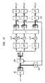
- FIG. 11illustrates an exemplary application of the envelope shaping scheme of FIG. 10 in the context of the BCC synthesizer of FIG. 4 ;
- FIG. 12illustrates an alternative exemplary application of the envelope shaping scheme of FIG. 10 in the context of the BCC synthesizer of FIG. 4 , where envelope shaping is applied to in the time domain;
- FIGS. 13( a ) and ( b )show possible implementations of the TPA and the TP of FIG. 12 , where envelope shaping is applied only at frequencies higher than the cut-off frequency f TP ;
- FIG. 14illustrates an exemplary application of the envelope shaping scheme of FIG. 10 in the context of the late reverberation-based ICC synthesis scheme described in U.S. application Ser. No. 10/815,591, filed on Apr. 1, 2004 as attorney docket no. Baumgarte 7-12;
- FIG. 15shows a block diagram representing at least a portion of a BCC decoder, according to an embodiment of the present invention that is an alternative to the scheme shown in FIG. 10 ;
- FIG. 16shows a block diagram representing at least a portion of a BCC decoder, according to an embodiment of the present invention that is an alternative to the schemes shown in FIGS. 10 and 15 ;
- FIG. 17illustrates an exemplary application of the envelope shaping scheme of FIG. 15 in the context of the BCC synthesizer of FIG. 4 ;
- FIGS. 18( a )-( c )show block diagrams of possible implementations of the TPA, ITP, and TP of FIG. 17 .
- an encoderencodes C input audio channels to generate E transmitted audio channels, where C>E ⁇ 1.
- C input channelsare provided in a frequency domain, and one or more cue codes are generated for each of one or more different frequency bands in the two or more input channels in the frequency domain.
- the C input channelsare downmixed to generate the E transmitted channels.
- at least one of the E transmitted channelsis based on two or more of the C input channels, and at least one of the E transmitted channels is based on only a single one of the C input channels.
- a BCC coderhas two or more filter banks, a code estimator, and a downmixer.
- the two or more filter banksconvert two or more of the C input channels from a time domain into a frequency domain.
- the code estimatorgenerates one or more cue codes for each of one or more different frequency bands in the two or more converted input channels.
- the downmixerdownmixes the C input channels to generate the E transmitted channels, where C>E ⁇ 1.
- E transmitted audio channelsare decoded to generate C playback audio channels.
- one or more of the E transmitted channelsare upmixed in a frequency domain to generate two or more of the C playback channels in the frequency domain, where C>E ⁇ 1.
- One or more cue codesare applied to each of the one or more different frequency bands in the two or more playback channels in the frequency domain to generate two or more modified channels, and the two or more modified channels are converted from the frequency domain into a time domain.
- At least one of the C playback channelsis based on at least one of the E transmitted channels and at least one cue code, and at least one of the C playback channels is based on only a single one of the E transmitted channels and independent of any cue codes.
- a BCC decoderhas an upmixer, a synthesizer, and one or more inverse filter banks.
- the upmixerupmixes one or more of the E transmitted channels in a frequency domain to generate two or more of the C playback channels in the frequency domain, where C>E ⁇ 1.
- the synthesizerapplies one or more cue codes to each of the one or more different frequency bands in the two or more playback channels in the frequency domain to generate two or more modified channels.
- the one or more inverse filter banksconvert the two or more modified channels from the frequency domain into a time domain.
- a given playback channelmay be based on a single transmitted channel, rather than a combination of two or more transmitted channels.
- each of the C playback channelsis based on that one transmitted channel.
- upmixingcorresponds to copying of the corresponding transmitted channel.
- the upmixermay be implemented using a replicator that copies the transmitted channel for each playback channel.
- BCC encoders and/or decodersmay be incorporated into a number of systems or applications including, for example, digital video recorders/players, digital audio recorders/players, computers, satellite transmitters/receivers, cable transmitters/receivers, terrestrial broadcast transmitters/receivers, home entertainment systems, and movie theater systems.
- FIG. 2is a block diagram of a generic binaural cue coding (BCC) audio processing system 200 comprising an encoder 202 and a decoder 204 .
- Encoder 202includes downmixer 206 and BCC estimator 208 .
- Downmixer 206converts C input audio channels x i (n) into E transmitted audio channels y i (n), where C>E ⁇ 1.
- signals expressed using the variable nare time-domain signals
- signals expressed using the variable kare frequency-domain signals.
- BCC estimator 208generates BCC codes from the C input audio channels and transmits those BCC codes as either in-band or out-of-band side information relative to the E transmitted audio channels.
- Typical BCC codesinclude one or more of inter-channel time difference (ICTD), inter-channel level difference (ICLD), and inter-channel correlation (ICC) data estimated between certain pairs of input channels as a function of frequency and time. The particular implementation will dictate between which particular pairs of input channels, BCC codes are estimated.
- ICC datacorresponds to the coherence of a binaural signal, which is related to the perceived width of the audio source.
- the coherence of the binaural signal corresponding to an orchestra spread out over an auditorium stageis typically lower than the coherence of the binaural signal corresponding to a single violin playing solo.
- an audio signal with lower coherenceis usually perceived as more spread out in auditory space.
- ICC datais typically related to the apparent source width and degree of listener envelopment. See, e.g., J. Blauert, The Psychophysics of Human Sound Localization , MIT Press, 1983.
- the E transmitted audio channels and corresponding BCC codesmay be transmitted directly to decoder 204 or stored in some suitable type of storage device for subsequent access by decoder 204 .
- the term “transmitting”may refer to either direct transmission to a decoder or storage for subsequent provision to a decoder.
- decoder 204receives the transmitted audio channels and side information and performs upmixing and BCC synthesis using the BCC codes to convert the E transmitted audio channels into more than E (typically, but not necessarily, C) playback audio channels ⁇ circumflex over (x) ⁇ i (n) for audio playback.
- upmixingcan be performed in either the time domain or the frequency domain.
- a generic BCC audio processing systemmay include additional encoding and decoding stages to further compress the audio signals at the encoder and then decompress the audio signals at the decoder, respectively.
- These audio codecsmay be based on conventional audio compression/decompression techniques such as those based on pulse code modulation (PCM), differential PCM (DPCM), or adaptive DPCM (ADPCM).
- PCMpulse code modulation
- DPCMdifferential PCM
- ADPCMadaptive DPCM
- BCC codingis able to represent multi-channel audio signals at a bitrate only slightly higher than what is required to represent a mono audio signal. This is so, because the estimated ICTD, ICLD, and ICC data between a channel pair contain about two orders of magnitude less information than an audio waveform.
- a single transmitted sum signalcorresponds to a mono downmix of the original stereo or multi-channel signal.
- listening to the transmitted sum signalis a valid method of presenting the audio material on low-profile mono reproduction equipment.
- BCC codingcan therefore also be used to enhance existing services involving the delivery of mono audio material towards multi-channel audio.
- existing mono audio radio broadcasting systemscan be enhanced for stereo or multi-channel playback if the BCC side information can be embedded into the existing transmission channel.
- Analogous capabilitiesexist when downmixing multi-channel audio to two sum signals that correspond to stereo audio.
- BCCprocesses audio signals with a certain time and frequency resolution.
- the frequency resolution usedis largely motivated by the frequency resolution of the human auditory system.
- Psychoacousticssuggests that spatial perception is most likely based on a critical band representation of the acoustic input signal.
- This frequency resolutionis considered by using an invertible filterbank (e.g., based on a fast Fourier transform (FFT) or a quadrature mirror filter (QMF)) with subbands with bandwidths equal or proportional to the critical bandwidth of the human auditory system.
- FFTfast Fourier transform
- QMFquadrature mirror filter
- the transmitted sum signal(s)contain all signal components of the input audio signal.
- the goalis that each signal component is fully maintained.
- Simply summation of the audio input channelsoften results in amplification or attenuation of signal components.
- the power of the signal components in a “simple” sumis often larger or smaller than the sum of the power of the corresponding signal component of each channel.
- a downmixing techniquecan be used that equalizes the sum signal such that the power of signal components in the sum signal is approximately the same as the corresponding power in all input channels.
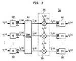
- FIG. 3shows a block diagram of a downmixer 300 that can be used for downmixer 206 of FIG. 2 according to certain implementations of BCC system 200 .
- Downmixer 300has a filter bank (FB) 302 for each input channel x i (n), a downmixing block 304 , an optional scaling/delay block 306 , and an inverse FB (IFB) 308 for each encoded channel y i (n).
- FBfilter bank
- IFBinverse FB
- Each filter bank 302converts each frame (e.g., 20 msec) of a corresponding digital input channel x i (n) in the time domain into a set of input coefficients ⁇ tilde over (x) ⁇ i (k) in the frequency domain.
- Downmixing block 304downmixes each sub-band of C corresponding input coefficients into a corresponding sub-band of E downmixed frequency-domain coefficients.
- Equation (1)represents the downmixing of the kth sub-band of input coefficients ( ⁇ tilde over (x) ⁇ 1 (k), ⁇ tilde over (x) ⁇ 2 (k), . . . , ⁇ tilde over (x) ⁇ C (k)) to generate the kth sub-band of downmixed coefficients ( ⁇ 1 (k), ⁇ 2 (k), . . . , ⁇ E (k)) as follows:
- Optional scaling/delay block 306comprises a set of multipliers 310 , each of which multiplies a corresponding downmixed coefficient ⁇ i (k) by a scaling factor e i (k) to generate a corresponding scaled coefficient ⁇ tilde over (y) ⁇ i (k).
- the motivation for the scaling operationis equivalent to equalization generalized for downmixing with arbitrary weighting factors for each channel. If the input channels are independent, then the power p ⁇ tilde over (y) ⁇ i (k) of the downmixed signal in each sub-band is given by Equation (2) as follows:
- Equation (1)the power values p ⁇ tilde over (y) ⁇ i (k) of the downmixed signal will be larger or smaller than that computed using Equation (2), due to signal amplifications or cancellations when signal components are in-phase or out-of-phase, respectively.
- Equation (2)the downmixing operation of Equation (1) is applied in sub-bands followed by the scaling operation of multipliers 310 .
- the scaling factors e i (k) (1 ⁇ i ⁇ E)can be derived using Equation (3) as follows:
- e i ⁇ ( k )p y ⁇ i ⁇ ( k ) p y ⁇ i ⁇ ( k ) , ( 3 )
- p ⁇ tilde over (y) ⁇ k (k)is the sub-band power as computed by Equation (2)
- p ⁇ i (k)is power of the corresponding downmixed sub-band signal ⁇ i (k).
- scaling/delay block 306may optionally apply delays to the signals.
- Each inverse filter bank 308converts a set of corresponding scaled coefficients ⁇ tilde over (y) ⁇ i (k) in the frequency domain into a frame of a corresponding digital, transmitted channel y i (n).
- FIG. 3shows all C of the input channels being converted into the frequency domain for subsequent downmixing
- one or more (but less than C ⁇ 1) of the C input channelsmight bypass some or all of the processing shown in FIG. 3 and be transmitted as an equivalent number of unmodified audio channels.
- these unmodified audio channelsmight or might not be used by BCC estimator 208 of FIG. 2 in generating the transmitted BCC codes.
- Equation (4)Equation (4)
- Equation (5)the factor e(k) is given by Equation (5) as follows:
- FIG. 4shows a block diagram of a BCC synthesizer 400 that can be used for decoder 204 of FIG. 2 according to certain implementations of BCC system 200 .
- BCC synthesizer 400has a filter bank 402 for each transmitted channel y i (n), an upmixing block 404 , delays 406 , multipliers 408 , correlation block 410 , and an inverse filter bank 412 for each playback channel ⁇ circumflex over (x) ⁇ i (n).
- Each filter bank 402converts each frame of a corresponding digital, transmitted channel y i (n) in the time domain into a set of input coefficients ⁇ tilde over (y) ⁇ i (k) in the frequency domain.
- Upmixing block 404upmixes each sub-band of E corresponding transmitted-channel coefficients into a corresponding sub-band of C upmixed frequency-domain coefficients. Equation (4) represents the upmixing of the kth sub-band of transmitted-channel coefficients ( ⁇ tilde over (y) ⁇ 1 (k), ⁇ tilde over (y) ⁇ 2 (k), . . .
- Each delay 406applies a delay value d i (k) based on a corresponding BCC code for ICTD data to ensure that the desired ICTD values appear between certain pairs of playback channels.
- Each multiplier 408applies a scaling factor a i (k) based on a corresponding BCC code for ICLD data to ensure that the desired ICLD values appear between certain pairs of playback channels.
- Correlation block 410performs a decorrelation operation A based on corresponding BCC codes for ICC data to ensure that the desired ICC values appear between certain pairs of playback channels. Further description of the operations of correlation block 410 can be found in U.S.
- ICLD valuesmay be less troublesome than the synthesis of ICTD and ICC values, since ICLD synthesis involves merely scaling of sub-band signals. Since ICLD cues are the most commonly used directional cues, it is usually more important that the ICLD values approximate those of the original audio signal. As such, ICLD data might be estimated between all channel pairs.
- the scaling factors a i (k) (1 ⁇ i ⁇ C) for each sub-bandare preferably chosen such that the sub-band power of each playback channel approximates the corresponding power of the original input audio channel.
- One goalmay be to apply relatively few signal modifications for synthesizing ICTD and ICC values.
- the BCC datamight not include ICTD and ICC values for all channel pairs.
- BCC synthesizer 400would synthesize ICTD and ICC values only between certain channel pairs.
- Each inverse filter bank 412converts a set of corresponding synthesized coefficients ⁇ circumflex over ( ⁇ tilde over (x) ⁇ i (k) in the frequency domain into a frame of a corresponding digital, playback channel ⁇ circumflex over (x) ⁇ i (n).
- FIG. 4shows all E of the transmitted channels being converted into the frequency domain for subsequent upmixing and BCC processing
- one or more (but not all) of the E transmitted channelsmight bypass some or all of the processing shown in FIG. 4 .
- one or more of the transmitted channelsmay be unmodified channels that are not subjected to any upmixing.
- these unmodified channelsmight be, but do not have to be, used as reference channels to which BCC processing is applied to synthesize one or more of the other playback channels.
- such unmodified channelsmay be subjected to delays to compensate for the processing time involved in the upmixing and/or BCC processing used to generate the rest of the playback channels.
- FIG. 4shows C playback channels being synthesized from E transmitted channels, where C was also the number of original input channels, BCC synthesis is not limited to that number of playback channels.
- the number of playback channelscan be any number of channels, including numbers greater than or less than C and possibly even situations where the number of playback channels is equal to or less than the number of transmitted channels.
- BCCsynthesizes a stereo or multi-channel audio signal such that ICTD, ICLD, and ICC approximate the corresponding cues of the original audio signal.
- ICTD, ICLD, and ICCapproximate the corresponding cues of the original audio signal.
- ICTD and ICLDare related to perceived direction.
- BRIRsbinaural room impulse responses
- Stereo and multi-channel audio signalsusually contain a complex mix of concurrently active source signals superimposed by reflected signal components resulting from recording in enclosed spaces or added by the recording engineer for artificially creating a spatial impression.
- Different source signals and their reflectionsoccupy different regions in the time-frequency plane. This is reflected by ICTD, ICLD, and ICC, which vary as a function of time and frequency.
- ICTD, ICLD, and ICCwhich vary as a function of time and frequency.
- the strategy of certain embodiments of BCCis to blindly synthesize these cues such that they approximate the corresponding cues of the original audio signal.
- Filterbanks with subbands of bandwidths equal to two times the equivalent rectangular bandwidth (ERB)are used. Informal listening reveals that the audio quality of BCC does not notably improve when choosing higher frequency resolution. A lower frequency resolution may be desired, since it results in less ICTD, ICLD, and ICC values that need to be transmitted to the decoder and thus in a lower bitrate.
- ICTD, ICLD, and ICCare typically considered at regular time intervals. High performance is obtained when ICTD, ICLD, and ICC are considered about every 4 to 16 ms. Note that, unless the cues are considered at very short time intervals, the precedence effect is not directly considered. Assuming a classical lead-lag pair of sound stimuli, if the lead and lag fall into a time interval where only one set of cues is synthesized, then localization dominance of the lead is not considered. Despite this, BCC achieves audio quality reflected in an average MUSHRA score of about 87 (i.e., “excellent” audio quality) on average and up to nearly 100 for certain audio signals.
- bitrate for transmission of these (quantized and coded) spatial cuescan be just a few kb/s and thus, with BCC, it is possible to transmit stereo and multi-channel audio signals at bitrates close to what is required for a single audio channel.
- FIG. 5shows a block diagram of BCC estimator 208 of FIG. 2 , according to one embodiment of the present invention.
- BCC estimator 208comprises filterbanks (FB) 502 , which may be the same as filterbanks 302 of FIG. 3 , and estimation block 504 , which generates ICTD, ICLD, and ICC spatial cues for each different frequency subband generated by filterbanks 502 .
- FBfilterbanks
- d 1max ⁇ ⁇ - d , 0 ⁇ ( 9 )
- d 2max ⁇ ⁇ d , 0 ⁇
- p ⁇ tilde over (x) ⁇ 1 ⁇ tilde over (x) ⁇ 2 (d, k)is a short-time estimate of the mean of ⁇ tilde over (x) ⁇ 1 (k ⁇ d 1 ) ⁇ tilde over (x) ⁇ 2 (k ⁇ d 2 ).
- a reference channele.g., channel number 1
- ⁇ L 12 (k)denote the ICTD and ICLD, respectively, between the reference channel 1 and channel c.
- ICCtypically has more degrees of freedom.
- the ICC as definedcan have different values between all possible input channel pairs. For C channels, there are C(C ⁇ 1)/2 possible channel pairs; e.g., for 5 channels there are 10 channel pairs as illustrated in FIG. 7( a ).
- C(C ⁇ 1)/2 ICC valuesare estimated and transmitted, resulting in high computational complexity and high bitrate.
- ICTD and ICLDdetermine the direction at which the auditory event of the corresponding signal component in the subband is rendered.
- One single ICC parameter per subbandmay then be used to describe the overall coherence between all audio channels. Good results can be obtained by estimating and transmitting ICC cues only between the two channels with most energy in each subband at each time index. This is illustrated in FIG. 7( b ), where for time instants k ⁇ 1 and k the channel pairs (3, 4) and (1, 2) are strongest, respectively.
- a heuristic rulemay be used for determining ICC between the other channel pairs.
- FIG. 8shows a block diagram of an implementation of BCC synthesizer 400 of FIG. 4 that can be used in a BCC decoder to generate a stereo or multi-channel audio signal given a single transmitted sum signal s(n) plus the spatial cues.
- the sum signal s(n)is decomposed into subbands, where ⁇ tilde over (s) ⁇ (k) denotes one such subband.
- delays d cFor generating the corresponding subbands of each of the output channels, delays d c , scale factors a c , and filters h c are applied to the corresponding subband of the sum signal.
- ICTDare synthesized by imposing delays, ICLD by scaling, and ICC by applying de-correlation filters. The processing shown in FIG. 8 is applied independently to each subband.
- the delays d care determined from the ICTDs ⁇ 1c (k), according to Equation (12) as follows:
- the delay for the reference channel, d 1is computed such that the maximum magnitude of the delays d c is minimized.
- the output subbandsare preferably normalized such that the sum of the power of all output channels is equal to the power of the input sum signal. Since the total original signal power in each subband is preserved in the sum signal, this normalization results in the absolute subband power for each output channel approximating the corresponding power of the original encoder input audio signal. Given these constraints, the scale factors a c are given by Equation (14) as follows:
- the aim of ICC synthesisis to reduce correlation between the subbands after delays and scaling have been applied, without affecting ICTD and ICLD. This can be achieved by designing the filters h c in FIG. 8 such that ICTD and ICLD are effectively varied as a function of frequency such that the average variation is zero in each subband (auditory critical band).
- FIG. 9illustrates how ICTD and ICLD are varied within a subband as a function of frequency.
- the amplitude of ICTD and ICLD variationdetermines the degree of de-correlation and is controlled as a function of ICC. Note that ICTD are varied smoothly (as in FIG. 9( a )), while ICLD are varied randomly (as in FIG. 9( b )).
- ICTDare varied smoothly (as in FIG. 9( a )
- ICLDare varied randomly (as in FIG. 9( b )).
- BCCcan be implemented with more than one transmission channel.
- a variation of BCCwhich represents C audio channels not as one single (transmitted) channel, but as E channels, denoted C-to-E BCC.
- C-to-E BCCThere are (at least) two motivations for C-to-E BCC:
- BCC codinginvolves algorithms for ICTD, ICLD, and ICC synthesis.
- ICC cuescan be synthesized by means of de-correlating the signal components in the corresponding subbands. This can be done by frequency-dependent variation of ICLD, frequency-dependent variation of ICTD and ICLD, all-pass filtering, or with ideas related to reverberation algorithms.
- a generic principle of certain embodiments of the present inventionrelates to the observation that the sound synthesized by a BCC decoder should not only have spectral characteristics that are similar to that of the original sound, but also resemble the temporal envelope of the original sound quite closely in order to have similar perceptual characteristics.
- thisis achieved in BCC-like schemes by including a dynamic ICLD synthesis that applies a time-varying scaling operation to approximate each signal channel's temporal envelope.
- the temporal resolution of this processmay, however, not be sufficient to produce synthesized signals that approximate the original temporal envelope closely enough. This section describes a number of approaches to do this with a sufficiently fine time resolution.
- the ideais to take the temporal envelope of the transmitted “sum signal(s)” as an approximation instead. As such, there is no side information necessary to be transmitted from the BCC encoder to the BCC decoder in order to convey such envelope information.
- the inventionrelies on the following principle:
- FIG. 10shows a block diagram representing at least a portion of a BCC decoder 1000 , according to one embodiment of the present invention.
- block 1002represents BCC synthesis processing that includes, at least, ICC synthesis.
- BCC synthesis block 1002receives base channels 1001 and generates synthesized channels 1003 .
- block 1002represents the processing of blocks 406 , 408 , and 410 of FIG. 4 , where base channels 1001 are the signals generated by upmixing block 404 and synthesized channels 1003 are the signals generated by correlation block 410 .
- FIG. 10represents the processing implemented for one base channel 1001 ′ and its corresponding synthesized channel. Similar processing is also applied to each other base channel and its corresponding synthesized channel.
- Envelope extractor 1004determines the fine temporal envelope a of base channel 1001 ′
- envelope extractor 1006determines the fine temporal envelope b of synthesized channel 1003 ′
- Inverse envelope adjuster 1008uses temporal envelope b from envelope extractor 1006 to normalize the envelope (i.e., “flatten” the temporal fine structure) of synthesized channel 1003 ′ to produce a flattened signal 1005 ′ having a flat (e.g., uniform) time envelope.
- the flatteningcan be applied either before or after upmixing.
- Envelope adjuster 1010uses temporal envelope a from envelope extractor 1004 to re-impose the original signal envelope on the flattened signal 1005 ′ to generate output signal 1007 ′ having a temporal envelope substantially equal to the temporal envelope of base channel 1001 .
- this temporal envelope processingmay be applied to the entire synthesized channel (as shown) or only to the orthogonalized part (e.g., late-reverberation part, de-correlated part) of the synthesized channel (as described subsequently).
- envelope shapingmay be applied either to time-domain signals or in a frequency-dependent fashion (e.g., where the temporal envelope is estimated and imposed individually at different frequencies).
- Inverse envelope adjuster 1008 and envelope adjuster 1010may be implemented in different ways.
- a signal's envelopeis manipulated by multiplication of the signal's time-domain samples (or spectral/subband samples) with a time-varying amplitude modification function (e.g., 1/b for inverse envelope adjuster 1008 and a for envelope adjuster 1010 ).
- a convolution/filtering of the signal's spectral representation over frequencycan be used in a manner analogous to that used in the prior art for the purpose of shaping the quantization noise of a low bitrate audio coder.
- the temporal envelope of signalsmay be extracted either directly by analysis the signal's time structure or by examining the autocorrelation of the signal spectrum over frequency.
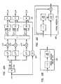
- FIG. 11illustrates an exemplary application of the envelope shaping scheme of FIG. 10 in the context of BCC synthesizer 400 of FIG. 4 .
- the C base signalsare generated by replicating that sum signal, and envelope shaping is individually applied to different subbands.
- envelope shapingis not restricted to processing each subband independently. This is especially true for convolution/filtering-based implementations that exploit covariance over frequency bands to derive information on the signal's temporal fine structure.
- temporal process analyzer (TPA) 1104is analogous to envelope extractor 1004 of FIG. 10
- each temporal processor (TP) 1106is analogous to the combination of envelope extractor 1006 , inverse envelope adjuster 1008 , and envelope adjuster 1010 of FIG. 10 .
- FIG. 11( b )shows a block diagram of one possible time domain-based implementation of TPA 1104 in which the base signal samples are squared ( 1110 ) and then low-pass filtered ( 1112 ) to characterize the temporal envelope a of the base signal.
- FIG. 11( c )shows a block diagram of one possible time domain-based implementation of TP 1106 in which the synthesized signal samples are squared ( 1114 ) and then low-pass filtered ( 1116 ) to characterize the temporal envelope b of the synthesized signal.
- a scale factore.g., sqrt (a/b)
- sqrta/b
- the temporal envelopesare characterized using magnitude operations rather than by squaring the signal samples.
- the ratio a/bmay be used as the scale factor without having to apply the square root operation.
- TP processing(as well as TPA and inverse TP (ITP) processing) can also be implemented using frequency-domain signals, as in the embodiment of FIGS. 17-18 (described below).
- scaling functionshould be interpreted to cover either time-domain or frequency-domain operations, such as the filtering operations of FIGS. 18( b ) and ( c ).
- TPA 1104 and TP 1106are preferably designed such that they do not modify signal power (i.e., energy).
- this signal powermay be a short-time average signal power in each channel, e.g., based on the total signal power per channel in the time period defined by the synthesis window or some other suitable measure of power.
- scaling for ICLD synthesise.g., using multipliers 408
- FIG. 11( a )for each channel, there are two outputs, where TP processing is applied to only one of them.
- Thisreflects an ICC synthesis scheme that mixes two signal components: unmodified and orthogonalized signals, where the ratio of unmodified and orthogonalized signal components determines the ICC.
- TPis applied to only the orthogonalized signal component, where summation nodes 1108 recombine the unmodified signal components with the corresponding temporally shaped, orthogonalized signal components.
- FIG. 12illustrates an alternative exemplary application of the envelope shaping scheme of FIG. 10 in the context of BCC synthesizer 400 of FIG. 4 , where envelope shaping is applied to in the time domain.
- envelope shapingis applied to in the time domain.
- Such an embodimentmay be warranted when the time resolution of the spectral representation in which ICTD, ICLD, and ICC synthesis is carried out is not high enough for effectively preventing “pre-echoes” by imposing the desired temporal envelope. For example, this may be the case when BCC is implemented with a short-time Fourier transform (STFT).
- STFTshort-time Fourier transform
- TPA 1204 and each TP 1206are implemented in the time domain, where the full-band signal is scaled such that it has the desired temporal envelope (e.g., the envelope as estimated from the transmitted sum signal).
- FIGS. 12( b ) and ( c )shows possible implementations of TPA 1204 and TP 1206 that are analogous to those shown in FIGS. 11( b ) and ( c ).
- TP processingis applied to the output signal, not only to the orthogonalized signal components.
- time domain-based TP processingcan be applied just to the orthogonalized signal components if so desired, in which case unmodified and orthogonalized subbands would be converted to the time domain with separate inverse filterbanks.
- envelope shapingmight be applied only at specified frequencies, for example, frequencies larger than a certain cut-off frequency f TP (e.g., 500 Hz).
- f TPcut-off frequency
- the frequency range for analysis (TPA)may differ from the frequency range for synthesis (TP).
- FIGS. 13( a ) and ( b )show possible implementations of TPA 1204 and TP 1206 where envelope shaping is applied only at frequencies higher than the cut-off frequency f TP .
- FIG. 13( a )shows the addition of high-pass filter 1302 , which filters out frequencies lower than f TP prior to temporal envelope characterization.
- FIG. 13( b )shows the addition of two-band filterbank 1304 having with a cut-off frequency of f TP between the two subbands, where only the high-frequency part is temporally shaped.
- Two-band inverse filterbank 1306then recombines the low-frequency part with the temporally shaped, high-frequency part to generate the output signal.
- FIG. 14illustrates an exemplary application of the envelope shaping scheme of FIG. 10 in the context of the late reverberation-based ICC synthesis scheme described in U.S. application Ser. No. 10/815,591, filed on Apr. 1, 2004 as attorney docket no. Baumgarte 7-12.
- TPA 1404 and each TP 1406are applied in the time domain, as in FIG. 12 or FIG. 13 , but where each TP 1406 is applied to the output from a different late reverberation (LR) block 1402 .
- LRlate reverberation
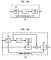
- FIG. 15shows a block diagram representing at least a portion of a BCC decoder 1500 , according to an embodiment of the present invention that is an alternative to the scheme shown in FIG. 10 .
- BCC synthesis block 1502 , envelope extractor 1504 , and envelope adjuster 1510are analogous to BCC synthesis block 1002 , envelope extractor 1004 , and envelope adjuster 1010 of FIG. 10 .
- inverse envelope adjuster 1508is applied prior to BCC synthesis, rather than after BCC synthesis, as in FIG. 10 . In this way, inverse envelope adjuster 1508 flattens the base channel before BCC synthesis is applied.
- FIG. 16shows a block diagram representing at least a portion of a BCC decoder 1600 , according to an embodiment of the present invention that is an alternative to the schemes shown in FIGS. 10 and 15 .
- envelope extractor 1604 and envelope adjuster 1610are analogous to envelope extractor 1504 and envelope adjuster 1510 of FIG. 15 .
- synthesis block 1602represents late reverberation-based ICC synthesis similar to that shown in FIG. 16 .
- envelope shapingis applied only to the uncorrelated late-reverberation signal, and summation node 1612 adds the temporally shaped, late-reverberation signal to the original base channel (which already has the desired temporal envelope).
- an inverse envelope adjusterdoes not need to be applied, because the late-reverberation signal has an approximately flat temporal envelope due to its generation process in block 1602 .
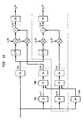
- FIG. 17illustrates an exemplary application of the envelope shaping scheme of FIG. 15 in the context of BCC synthesizer 400 of FIG. 4 .
- TPA 1704inverse TP (ITP) 1708
- TP 1710are analogous to envelope extractor 1504 , inverse envelope adjuster 1508 , and envelope adjuster 1510 of FIG. 15 .
- envelope shaping of diffuse soundis implemented by applying a convolution to the frequency bins of (e.g., STFT) filterbank 402 along the frequency axis.
- STFTfrequency bins of filterbank 402 along the frequency axis.
- FIG. 18( a )shows a block diagram of one possible implementation of TPA 1704 of FIG. 17 .
- TPA 1704is implemented as a linear predictive coding (LPC) analysis operation that determines the optimum prediction coefficients for the series of spectral coefficients over frequency.
- LPC analysis techniquesare well-known e.g., from speech coding and many algorithms for efficient calculation of LPC coefficients are known, such as the autocorrelation method (involving the calculation of the signal's autocorrelation function and a subsequent Levinson-Durbin recursion).
- the autocorrelation methodinvolving the calculation of the signal's autocorrelation function and a subsequent Levinson-Durbin recursion.
- a set of LPC coefficientsare available at the output that represent the signal's temporal envelope.
- FIGS. 18( b ) and ( c )show block diagrams of possible implementations of ITP 1708 and TP 1710 of FIG. 17 .
- the spectral coefficients of the signal to be processedare processed in order of (increasing or decreasing) frequency, which is symbolized here by rotating switch circuitry, converting these coefficients into a serial order for processing by a predictive filtering process (and back again after this processing).
- the predictive filteringcalculates the prediction residual and in this way “flattens” the temporal signal envelope.
- the inverse filterre-introduces the temporal envelope represented by the LPC coefficients from TPA 1704 .
- the convolution/filtering-based technique of FIG. 17can also be applied in the context of the envelope shaping scheme of FIG. 16 , where envelope extractor 1604 and envelope adjuster 1610 are based on the TPA of FIG. 18( a ) and the TP of FIG. 18( c ), respectively.
- BCC decoderscan be designed to selectively enable/disable envelope shaping.
- a BCC decodercould apply a conventional BCC synthesis scheme and enable the envelope shaping when the temporal envelope of the synthesized signal fluctuates sufficiently such that the benefits of envelope shaping dominate over any artifacts that envelope shaping may generate.
- This enabling/disabling controlcan be achieved by:
- TP processingis not applied when the tonality of the transmitted sum signal(s) is high.
- Similar measurescan be used in the BCC encoder to detect when TP processing should be active. Since the encoder has access to all original input signals, it may employ more sophisticated algorithms (e.g., a part of estimation block 208 ) to make a decision of when TP processing should be enabled. The result of this decision (a flag signaling when TP should be active) can be transmitted to the BCC decoder (e.g., as part of the side information of FIG. 2 ).
- the present inventionhas been described in the context of BCC coding schemes in which there is a single sum signal, the present invention can also be implemented in the context of BCC coding schemes having two or more sum signals.
- the temporal envelope for each different “base” sum signalcan be estimated before applying BCC synthesis, and different BCC output channels may be generated based on different temporal envelopes, depending on which sum signals were used to synthesize the different output channels.
- An output channel that is synthesized from two or more different sum channelscould be generated based on an effective temporal envelope that takes into account (e.g., via weighted averaging) the relative effects of the constituent sum channels.
- the present inventionhas been described in the context of BCC coding schemes involving ICTD, ICLD, and ICC codes, the present invention can also be implemented in the context of other BCC coding schemes involving only one or two of these three types of codes (e.g., ICLD and ICC, but not ICTD) and/or one or more additional types of codes.
- sequence of BCC synthesis processing and envelope shapingmay vary in different implementations. For example, when envelope shaping is applied to frequency-domain signals, as in FIGS. 14 and 16 , envelope shaping could alternatively be implemented after ICTD synthesis (in those embodiments that employ ICTD synthesis), but prior to ICLD synthesis. In other embodiments, envelope shaping could be applied to upmixed signals before any other BCC synthesis is applied.
- the present inventionhas been described in the context of BCC coding schemes, the present invention can also be implemented in the context of other audio processing systems in which audio signals are de-correlated or other audio processing that needs to de-correlate signals.
- the present inventionhas been described in the context of implementations in which the encoder receives input audio signal in the time domain and generates transmitted audio signals in the time domain and the decoder receives the transmitted audio signals in the time domain and generates playback audio signals in the time domain, the present invention is not so limited.
- any one or more of the input, transmitted, and playback audio signalscould be represented in a frequency domain.
- BCC encoders and/or decodersmay be used in conjunction with or incorporated into a variety of different applications or systems, including systems for television or electronic music distribution, movie theaters, broadcasting, streaming, and/or reception. These include systems for encoding/decoding transmissions via, for example, terrestrial, satellite, cable, internet, intranets, or physical media (e.g., compact discs, digital versatile discs, semiconductor chips, hard drives, memory cards, and the like).
- BCC encoders and/or decodersmay also be employed in games and game systems, including, for example, interactive software products intended to interact with a user for entertainment (action, role play, strategy, adventure, simulations, racing, sports, arcade, card, and board games) and/or education that may be published for multiple machines, platforms, or media. Further, BCC encoders and/or decoders may be incorporated in audio recorders/players or CD-ROM/DVD systems. BCC encoders and/or decoders may also be incorporated into PC software applications that incorporate digital decoding (e.g., player, decoder) and software applications incorporating digital encoding capabilities (e.g., encoder, ripper, recoder, and jukebox).
- digital decodinge.g., player, decoder
- software applications incorporating digital encoding capabilitiese.g., encoder, ripper, recoder, and jukebox.
- the present inventionmay be implemented as circuit-based processes, including possible implementation as a single integrated circuit (such as an ASIC or an FPGA), a multi-chip module, a single card, or a multi-card circuit pack.
- a single integrated circuitsuch as an ASIC or an FPGA
- a multi-chip modulesuch as a single card, or a multi-card circuit pack.
- various functions of circuit elementsmay also be implemented as processing steps in a software program.
- Such softwaremay be employed in, for example, a digital signal processor, micro-controller, or general-purpose computer.
- the present inventioncan be embodied in the form of methods and apparatuses for practicing those methods.
- the present inventioncan also be embodied in the form of program code embodied in tangible media, such as floppy diskettes, CD-ROMs, hard drives, or any other machine-readable storage medium, wherein, when the program code is loaded into and executed by a machine, such as a computer, the machine becomes an apparatus for practicing the invention.
- the present inventioncan also be embodied in the form of program code, for example, whether stored in a storage medium, loaded into and/or executed by a machine, or transmitted over some transmission medium or carrier, such as over electrical wiring or cabling, through fiber optics, or via electromagnetic radiation, wherein, when the program code is loaded into and executed by a machine, such as a computer, the machine becomes an apparatus for practicing the invention.
- program codeWhen implemented on a general-purpose processor, the program code segments combine with the processor to provide a unique device that operates analogously to specific logic circuits.
Landscapes
- Engineering & Computer Science (AREA)
- Physics & Mathematics (AREA)
- Signal Processing (AREA)
- Acoustics & Sound (AREA)
- Mathematical Physics (AREA)
- Computational Linguistics (AREA)
- Health & Medical Sciences (AREA)
- Audiology, Speech & Language Pathology (AREA)
- Human Computer Interaction (AREA)
- Multimedia (AREA)
- Mathematical Analysis (AREA)
- Algebra (AREA)
- Mathematical Optimization (AREA)
- Pure & Applied Mathematics (AREA)
- Theoretical Computer Science (AREA)
- General Physics & Mathematics (AREA)
- Stereophonic System (AREA)
- Tone Control, Compression And Expansion, Limiting Amplitude (AREA)
- Compression, Expansion, Code Conversion, And Decoders (AREA)
- Golf Clubs (AREA)
- Diaphragms For Electromechanical Transducers (AREA)
- Signal Processing Not Specific To The Method Of Recording And Reproducing (AREA)
- Electrophonic Musical Instruments (AREA)
- Control Of Amplification And Gain Control (AREA)
- Television Systems (AREA)
Abstract
Description
- U.S. application Ser. No. 09/848,877, filed on May 4, 2001;
- U.S. application Ser. No. 10/045,458, filed on Nov. 7, 2001, which itself claimed the benefit of the filing date of U.S. provisional application No. 60/311,565, filed on Aug. 10, 2001;
- U.S. application Ser. No. 10/155,437, filed on May 24, 2002;
- U.S. application Ser. No. 10/246,570, filed on Sep. 18, 2002;
- U.S. application Ser. No. 10/815,591, filed on Apr. 1, 2004;
- U.S. application Ser. No. 10/936,464, filed on Sep. 8, 2004;
- U.S. application Ser. No. 10/762,100, filed on Jan. 20, 2004 (Faller 13-1); and
- F. Baumgarte and C. Faller, “Binaural Cue Coding—Part I: Psychoacoustic fundamentals and design principles,”IEEE Trans. on Speech and Audio Proc., vol. 11, no. 6, November 2003;
- C. Faller and F. Baumgarte, “Binaural Cue Coding—Part II: Schemes and applications,”IEEE Trans. on Speech and Audio Proc., vol. 11, no. 6, November 2003; and
- C. Faller, “Coding of spatial audio compatible with different playback formats,”Preprint117thConv. Aud. Eng Soc., October 2004.
where DCEis a real-valued C-by-E downmixing matrix.
where
where p{tilde over (y)}
the factor e(k) is given by Equation (5) as follows:
where p{tilde over (x)}
The equalized subbands are transformed back to the time domain resulting in the sum signal y(n) that is transmitted to the BCC decoder.
Generic BCC Synthesis
where UECis a real-valued E-by-C upmixing matrix. Performing upmixing in the frequency-domain enables upmixing to be applied individually in each different sub-band.
with a short-time estimate of the normalized cross-correlation function given by Equation (8) as follows:
and p{tilde over (x)}
- Note that the absolute value of the normalized cross-correlation is considered and c12(k) has a range of [0,1].
Estimation of ICTD, ICLD, and ICC for Multi-Channel Audio Signals
- Note that the absolute value of the normalized cross-correlation is considered and c12(k) has a range of [0,1].
The delay for the reference channel, d1, is computed such that the maximum magnitude of the delays dcis minimized. The less the subband signals are modified, the less there is a danger for artifacts to occur. If the subband sampling rate does not provide high enough time-resolution for ICTD synthesis, delays can be imposed more precisely by using suitable all-pass filters.
ICLD Synthesis
Additionally, the output subbands are preferably normalized such that the sum of the power of all output channels is equal to the power of the input sum signal. Since the total original signal power in each subband is preserved in the sum signal, this normalization results in the absolute subband power for each output channel approximating the corresponding power of the original encoder input audio signal. Given these constraints, the scale factors acare given by Equation (14) as follows:
ICC Synthesis
- BCC with one transmission channel provides a backwards compatible path for upgrading existing mono systems for stereo or multi-channel audio playback. The upgraded systems transmit the BCC downmixed sum signal through the existing mono infrastructure, while additionally transmitting the BCC side information. C-to-E BCC is applicable to E-channel backwards compatible coding of C-channel audio.
- C-to-E BCC introduces scalability in terms of different degrees of reduction of the number of transmitted channels. It is expected that the more audio channels that are transmitted, the better the audio quality will be.
Signal processing details for C-to-E BCC, such as how to define the ICTD, ICLD, and ICC cues, are described in U.S. application Ser. No. 10/762,100, filed on Jan. 20, 2004 (Faller 13-1).
Diffuse Sound Shaping
- The transmitted audio channels (i.e., “sum channel(s)”)—or linear combinations of these channels which BCC synthesis may be based on—are analyzed by a temporal envelope extractor for their temporal envelope with a high time resolution (e.g., significantly finer than the BCC block size).
- The subsequent synthesized sound for each output channel is shaped such that—even after ICC synthesis—it matches the temporal envelope determined by the extractor as closely as possible. This ensures that, even in the case of transient signals, the synthesized output sound is not significantly degraded by the ICC synthesis/signal de-correlation process.
- (1) Transient detection: If a transient is detected, then TP processing is enabled. Transient detection can be implemented with in a look-ahead manner to effectively shape not only the transient but also the signal shortly before and after the transient. Possible ways of detecting transients include:
- Observing the temporal envelope of the transmitted BCC sum signal(s) to determine when there is a sudden increase in power indicating the occurrence of a transient; and
- Examining the gain of the predictive (LPC) filter. If the LPC prediction gain exceeds a specified threshold, it can be assumed that the signal is transient or highly fluctuating. The LPC analysis is computed on the spectrum's autocorrelation.
- (2) Randomness detection: There are scenarios when the temporal envelope is fluctuating pseudo-randomly. In such a scenario, no transient might be detected but TP processing could still be applied (e.g., a dense applause signal corresponds to such a scenario).
- (1) Transient detection: If a transient is detected, then TP processing is enabled. Transient detection can be implemented with in a look-ahead manner to effectively shape not only the transient but also the signal shortly before and after the transient. Possible ways of detecting transients include:
Claims (31)
Priority Applications (22)
| Application Number | Priority Date | Filing Date | Title |
|---|---|---|---|
| US11/006,492US8204261B2 (en) | 2004-10-20 | 2004-12-07 | Diffuse sound shaping for BCC schemes and the like |
| CN2010101384551ACN101853660B (en) | 2004-10-20 | 2005-09-12 | Diffuse sound envelope shaping for binaural cue coding schemes and the like |
| ES05785586TES2317297T3 (en) | 2004-10-20 | 2005-09-12 | CONFORMATION OF DIFFUSIVE SOUND ENVELOPE FOR BINAURAL AND SIMILAR INDICATION CODING SCHEMES. |
| EP05785586AEP1803325B1 (en) | 2004-10-20 | 2005-09-12 | Diffuse sound envelope shaping for binaural cue coding schemes and the like |
| HK07112769.7AHK1104412B (en) | 2004-10-20 | 2005-09-12 | Diffuse sound envelope shaping for binaural cue coding schemes and the like |
| JP2007537134AJP4625084B2 (en) | 2004-10-20 | 2005-09-12 | Shaped diffuse sound for binaural cue coding method etc. |
| PL05785586TPL1803325T3 (en) | 2004-10-20 | 2005-09-12 | Diffuse sound envelope shaping for binaural cue coding schemes and the like |
| RU2007118674/09ARU2384014C2 (en) | 2004-10-20 | 2005-09-12 | Generation of scattered sound for binaural coding circuits using key information |
| AT05785586TATE413792T1 (en) | 2004-10-20 | 2005-09-12 | DIFFUSE SOUND ENVELOPE SHAPING FOR BINAURAL CUE CODING PROCEDURES AND THE LIKE |
| PCT/EP2005/009784WO2006045373A1 (en) | 2004-10-20 | 2005-09-12 | Diffuse sound envelope shaping for binaural cue coding schemes and the like |
| DE602005010894TDE602005010894D1 (en) | 2004-10-20 | 2005-09-12 | DIFFUSHAIN SINGLE FORMING FOR BINAURALE NOTE CODING METHOD AND THE SAME |
| AU2005299070AAU2005299070B2 (en) | 2004-10-20 | 2005-09-12 | Diffuse sound envelope shaping for binaural cue coding schemes and the like |
| KR1020077008796AKR100922419B1 (en) | 2004-10-20 | 2005-09-12 | Diffuse sound envelope shaping for Binural Cue coding schemes and the like |
| MX2007004725AMX2007004725A (en) | 2004-10-20 | 2005-09-12 | Diffuse sound envelope shaping for binaural cue coding schemes and the like. |
| CN2005800359507ACN101044794B (en) | 2004-10-20 | 2005-09-12 | Method and apparatus for diffuse sound shaping for binaural cue code coding schemes and the like |
| PT05785586TPT1803325E (en) | 2004-10-20 | 2005-09-12 | Diffuse sound envelope shaping for binaural cue coding schemes and the like |
| BRPI0516392ABRPI0516392B1 (en) | 2004-10-20 | 2005-09-12 | diffuse sound conformation for bcc and similar schemes |
| CA2583146ACA2583146C (en) | 2004-10-20 | 2005-09-12 | Diffuse sound envelope shaping for binaural cue coding schemes and the like |
| TW094135353ATWI330827B (en) | 2004-10-20 | 2005-10-11 | Apparatus and method for converting input audio signal into output audio signal,apparatus and method for encoding c input audio ahannel to generate e transmitted audio channel,a storage device and a machine-readable medium |
| NO20071492ANO339587B1 (en) | 2004-10-20 | 2007-03-21 | Diffuse sound shaping for BCC procedures and the like. |
| IL182235AIL182235A (en) | 2004-10-20 | 2007-03-27 | Diffuse sound shaping for bcc schemes and the like |
| US12/550,519US8238562B2 (en) | 2004-10-20 | 2009-08-31 | Diffuse sound shaping for BCC schemes and the like |
Applications Claiming Priority (2)
| Application Number | Priority Date | Filing Date | Title |
|---|---|---|---|
| US62040104P | 2004-10-20 | 2004-10-20 | |
| US11/006,492US8204261B2 (en) | 2004-10-20 | 2004-12-07 | Diffuse sound shaping for BCC schemes and the like |
Related Child Applications (1)
| Application Number | Title | Priority Date | Filing Date |
|---|---|---|---|
| US12/550,519DivisionUS8238562B2 (en) | 2004-10-20 | 2009-08-31 | Diffuse sound shaping for BCC schemes and the like |
Publications (2)
| Publication Number | Publication Date |
|---|---|
| US20060085200A1 US20060085200A1 (en) | 2006-04-20 |
| US8204261B2true US8204261B2 (en) | 2012-06-19 |
Family
ID=36181866
Family Applications (2)
| Application Number | Title | Priority Date | Filing Date |
|---|---|---|---|
| US11/006,492Active2030-08-11US8204261B2 (en) | 2004-10-20 | 2004-12-07 | Diffuse sound shaping for BCC schemes and the like |
| US12/550,519Expired - LifetimeUS8238562B2 (en) | 2004-10-20 | 2009-08-31 | Diffuse sound shaping for BCC schemes and the like |
Family Applications After (1)
| Application Number | Title | Priority Date | Filing Date |
|---|---|---|---|
| US12/550,519Expired - LifetimeUS8238562B2 (en) | 2004-10-20 | 2009-08-31 | Diffuse sound shaping for BCC schemes and the like |
Country Status (19)
| Country | Link |
|---|---|
| US (2) | US8204261B2 (en) |
| EP (1) | EP1803325B1 (en) |
| JP (1) | JP4625084B2 (en) |
| KR (1) | KR100922419B1 (en) |
| CN (2) | CN101853660B (en) |
| AT (1) | ATE413792T1 (en) |
| AU (1) | AU2005299070B2 (en) |
| BR (1) | BRPI0516392B1 (en) |
| CA (1) | CA2583146C (en) |
| DE (1) | DE602005010894D1 (en) |
| ES (1) | ES2317297T3 (en) |
| IL (1) | IL182235A (en) |
| MX (1) | MX2007004725A (en) |
| NO (1) | NO339587B1 (en) |
| PL (1) | PL1803325T3 (en) |
| PT (1) | PT1803325E (en) |
| RU (1) | RU2384014C2 (en) |
| TW (1) | TWI330827B (en) |
| WO (1) | WO2006045373A1 (en) |
Cited By (6)
| Publication number | Priority date | Publication date | Assignee | Title |
|---|---|---|---|---|
| US20130132098A1 (en)* | 2006-12-27 | 2013-05-23 | Electronics And Telecommunications Research Institute | Apparatus and method for coding and decoding multi-object audio signal with various channel including information bitstream conversion |
| US9530422B2 (en) | 2013-06-27 | 2016-12-27 | Dolby Laboratories Licensing Corporation | Bitstream syntax for spatial voice coding |
| US20170301363A1 (en)* | 2012-04-27 | 2017-10-19 | Ntt Docomo, Inc. | Audio decoding device, audio coding device, audio decoding method, audio coding method, audio decoding program, and audio coding program |
| US9934789B2 (en)* | 2006-01-11 | 2018-04-03 | Samsung Electronics Co., Ltd. | Method, medium, and apparatus with scalable channel decoding |
| US10720170B2 (en) | 2016-02-17 | 2020-07-21 | Fraunhofer-Gesellschaft zur Förderung der angewandten Forschung e.V. | Post-processor, pre-processor, audio encoder, audio decoder and related methods for enhancing transient processing |
| US11929084B2 (en) | 2014-07-28 | 2024-03-12 | Fraunhofer-Gesellschaft zur Förderung der angewandten Forschung e.V. | Audio encoder and decoder using a frequency domain processor with full-band gap filling and a time domain processor |
Families Citing this family (84)
| Publication number | Priority date | Publication date | Assignee | Title |
|---|---|---|---|---|
| US8010174B2 (en) | 2003-08-22 | 2011-08-30 | Dexcom, Inc. | Systems and methods for replacing signal artifacts in a glucose sensor data stream |
| US8260393B2 (en) | 2003-07-25 | 2012-09-04 | Dexcom, Inc. | Systems and methods for replacing signal data artifacts in a glucose sensor data stream |
| US20140121989A1 (en) | 2003-08-22 | 2014-05-01 | Dexcom, Inc. | Systems and methods for processing analyte sensor data |
| DE102004043521A1 (en)* | 2004-09-08 | 2006-03-23 | Fraunhofer-Gesellschaft zur Förderung der angewandten Forschung e.V. | Device and method for generating a multi-channel signal or a parameter data set |
| JPWO2006059567A1 (en)* | 2004-11-30 | 2008-06-05 | 松下電器産業株式会社 | Stereo encoding apparatus, stereo decoding apparatus, and methods thereof |
| DE602006014809D1 (en)* | 2005-03-30 | 2010-07-22 | Koninkl Philips Electronics Nv | SCALABLE MULTICHANNEL AUDIO CODING |
| WO2006108543A1 (en)* | 2005-04-15 | 2006-10-19 | Coding Technologies Ab | Temporal envelope shaping of decorrelated signal |
| EP1905004A2 (en)* | 2005-05-26 | 2008-04-02 | LG Electronics Inc. | Method of encoding and decoding an audio signal |
| BRPI0611505A2 (en)* | 2005-06-03 | 2010-09-08 | Dolby Lab Licensing Corp | channel reconfiguration with secondary information |
| AU2006266655B2 (en)* | 2005-06-30 | 2009-08-20 | Lg Electronics Inc. | Apparatus for encoding and decoding audio signal and method thereof |
| US8494667B2 (en)* | 2005-06-30 | 2013-07-23 | Lg Electronics Inc. | Apparatus for encoding and decoding audio signal and method thereof |
| MX2008000122A (en)* | 2005-06-30 | 2008-03-18 | Lg Electronics Inc | Method and apparatus for encoding and decoding an audio signal. |
| EP1938663A4 (en)* | 2005-08-30 | 2010-11-17 | Lg Electronics Inc | Apparatus for encoding and decoding audio signal and method thereof |
| EP1922722A4 (en)* | 2005-08-30 | 2011-03-30 | Lg Electronics Inc | A method for decoding an audio signal |
| US8577483B2 (en)* | 2005-08-30 | 2013-11-05 | Lg Electronics, Inc. | Method for decoding an audio signal |
| US7788107B2 (en)* | 2005-08-30 | 2010-08-31 | Lg Electronics Inc. | Method for decoding an audio signal |
| MX2008002760A (en)* | 2005-08-30 | 2008-04-07 | Lg Electronics Inc | A method for decoding an audio signal. |
| EP1761110A1 (en) | 2005-09-02 | 2007-03-07 | Ecole Polytechnique Fédérale de Lausanne | Method to generate multi-channel audio signals from stereo signals |
| JP4918490B2 (en)* | 2005-09-02 | 2012-04-18 | パナソニック株式会社 | Energy shaping device and energy shaping method |
| US20080255857A1 (en)* | 2005-09-14 | 2008-10-16 | Lg Electronics, Inc. | Method and Apparatus for Decoding an Audio Signal |
| US7672379B2 (en)* | 2005-10-05 | 2010-03-02 | Lg Electronics Inc. | Audio signal processing, encoding, and decoding |
| US7751485B2 (en)* | 2005-10-05 | 2010-07-06 | Lg Electronics Inc. | Signal processing using pilot based coding |
| US7646319B2 (en)* | 2005-10-05 | 2010-01-12 | Lg Electronics Inc. | Method and apparatus for signal processing and encoding and decoding method, and apparatus therefor |
| US7696907B2 (en) | 2005-10-05 | 2010-04-13 | Lg Electronics Inc. | Method and apparatus for signal processing and encoding and decoding method, and apparatus therefor |
| EP1952112A4 (en)* | 2005-10-05 | 2010-01-13 | Lg Electronics Inc | SIGNAL PROCESSING METHOD AND APPARATUS, ENCODING AND DECODING METHOD, AND ASSOCIATED APPARATUS |
| KR100857117B1 (en)* | 2005-10-05 | 2008-09-05 | 엘지전자 주식회사 | Method and apparatus for signal processing and encoding and decoding method, and apparatus therefor |
| US8068569B2 (en)* | 2005-10-05 | 2011-11-29 | Lg Electronics, Inc. | Method and apparatus for signal processing and encoding and decoding |
| US7742913B2 (en)* | 2005-10-24 | 2010-06-22 | Lg Electronics Inc. | Removing time delays in signal paths |
| US20070133819A1 (en)* | 2005-12-12 | 2007-06-14 | Laurent Benaroya | Method for establishing the separation signals relating to sources based on a signal from the mix of those signals |
| ATE447224T1 (en)* | 2006-03-13 | 2009-11-15 | France Telecom | JOINT SOUND SYNTHESIS AND SPATALIZATION |
| CN101405792B (en)* | 2006-03-20 | 2012-09-05 | 法国电信公司 | Method for post-processing a signal in an audio decoder |
| JP4875142B2 (en)* | 2006-03-28 | 2012-02-15 | テレフオンアクチーボラゲット エル エム エリクソン(パブル) | Method and apparatus for a decoder for multi-channel surround sound |
| ATE527833T1 (en)* | 2006-05-04 | 2011-10-15 | Lg Electronics Inc | IMPROVE STEREO AUDIO SIGNALS WITH REMIXING |
| US8379868B2 (en)* | 2006-05-17 | 2013-02-19 | Creative Technology Ltd | Spatial audio coding based on universal spatial cues |
| US7876904B2 (en)* | 2006-07-08 | 2011-01-25 | Nokia Corporation | Dynamic decoding of binaural audio signals |
| WO2008039045A1 (en)* | 2006-09-29 | 2008-04-03 | Lg Electronics Inc., | Apparatus for processing mix signal and method thereof |
| US8625808B2 (en) | 2006-09-29 | 2014-01-07 | Lg Elecronics Inc. | Methods and apparatuses for encoding and decoding object-based audio signals |
| CN101529898B (en) | 2006-10-12 | 2014-09-17 | Lg电子株式会社 | Apparatus for processing a mix signal and method thereof |
| US7555354B2 (en)* | 2006-10-20 | 2009-06-30 | Creative Technology Ltd | Method and apparatus for spatial reformatting of multi-channel audio content |
| BRPI0718614A2 (en)* | 2006-11-15 | 2014-02-25 | Lg Electronics Inc | METHOD AND APPARATUS FOR DECODING AUDIO SIGNAL. |
| KR101062353B1 (en) | 2006-12-07 | 2011-09-05 | 엘지전자 주식회사 | Method for decoding audio signal and apparatus therefor |
| CN101568958B (en)* | 2006-12-07 | 2012-07-18 | Lg电子株式会社 | A method and an apparatus for processing an audio signal |
| WO2008082276A1 (en)* | 2007-01-05 | 2008-07-10 | Lg Electronics Inc. | A method and an apparatus for processing an audio signal |
| FR2911426A1 (en)* | 2007-01-15 | 2008-07-18 | France Telecom | MODIFICATION OF A SPEECH SIGNAL |
| US20100121470A1 (en)* | 2007-02-13 | 2010-05-13 | Lg Electronics Inc. | Method and an apparatus for processing an audio signal |
| KR20090122221A (en)* | 2007-02-13 | 2009-11-26 | 엘지전자 주식회사 | Audio signal processing method and apparatus |
| JP5355387B2 (en)* | 2007-03-30 | 2013-11-27 | パナソニック株式会社 | Encoding apparatus and encoding method |
| US8548615B2 (en)* | 2007-11-27 | 2013-10-01 | Nokia Corporation | Encoder |
| WO2009075510A1 (en)* | 2007-12-09 | 2009-06-18 | Lg Electronics Inc. | A method and an apparatus for processing a signal |
| US8386267B2 (en)* | 2008-03-19 | 2013-02-26 | Panasonic Corporation | Stereo signal encoding device, stereo signal decoding device and methods for them |
| KR101600352B1 (en)* | 2008-10-30 | 2016-03-07 | 삼성전자주식회사 | Apparatus and method for encoding / decoding multi-channel signals |
| CN102257562B (en) | 2008-12-19 | 2013-09-11 | 杜比国际公司 | Method and apparatus for applying reverberation to a multi-channel audio signal using spatial cue parameters |
| WO2010138311A1 (en)* | 2009-05-26 | 2010-12-02 | Dolby Laboratories Licensing Corporation | Equalization profiles for dynamic equalization of audio data |
| JP5365363B2 (en)* | 2009-06-23 | 2013-12-11 | ソニー株式会社 | Acoustic signal processing system, acoustic signal decoding apparatus, processing method and program therefor |
| JP2011048101A (en)* | 2009-08-26 | 2011-03-10 | Renesas Electronics Corp | Pixel circuit and display device |
| US8786852B2 (en) | 2009-12-02 | 2014-07-22 | Lawrence Livermore National Security, Llc | Nanoscale array structures suitable for surface enhanced raman scattering and methods related thereto |
| JP5508550B2 (en)* | 2010-02-24 | 2014-06-04 | フラウンホーファー−ゲゼルシャフト・ツール・フェルデルング・デル・アンゲヴァンテン・フォルシュング・アインゲトラーゲネル・フェライン | Apparatus for generating extended downmix signal, method and computer program for generating extended downmix signal |
| EP2362376A3 (en)* | 2010-02-26 | 2011-11-02 | Fraunhofer-Gesellschaft zur Förderung der Angewandten Forschung e.V. | Apparatus and method for modifying an audio signal using envelope shaping |
| KR102814254B1 (en) | 2010-04-09 | 2025-05-30 | 돌비 인터네셔널 에이비 | Mdct-based complex prediction stereo coding |
| KR20120004909A (en) | 2010-07-07 | 2012-01-13 | 삼성전자주식회사 | Stereo playback method and apparatus |
| US8908874B2 (en) | 2010-09-08 | 2014-12-09 | Dts, Inc. | Spatial audio encoding and reproduction |
| JP5681290B2 (en)* | 2010-09-28 | 2015-03-04 | ホアウェイ・テクノロジーズ・カンパニー・リミテッド | Device for post-processing a decoded multi-channel audio signal or a decoded stereo signal |
| WO2012040897A1 (en)* | 2010-09-28 | 2012-04-05 | Huawei Technologies Co., Ltd. | Device and method for postprocessing decoded multi-channel audio signal or decoded stereo signal |
| TR201815799T4 (en)* | 2011-01-05 | 2018-11-21 | Anheuser Busch Inbev Sa | An audio system and its method of operation. |
| TWI450266B (en)* | 2011-04-19 | 2014-08-21 | Hon Hai Prec Ind Co Ltd | Electronic device and decoding method of audio files |
| US9395304B2 (en) | 2012-03-01 | 2016-07-19 | Lawrence Livermore National Security, Llc | Nanoscale structures on optical fiber for surface enhanced Raman scattering and methods related thereto |
| EP2856776B1 (en) | 2012-05-29 | 2019-03-27 | Nokia Technologies Oy | Stereo audio signal encoder |
| US9460729B2 (en) | 2012-09-21 | 2016-10-04 | Dolby Laboratories Licensing Corporation | Layered approach to spatial audio coding |
| WO2014130585A1 (en)* | 2013-02-19 | 2014-08-28 | Max Sound Corporation | Waveform resynthesis |
| US9191516B2 (en)* | 2013-02-20 | 2015-11-17 | Qualcomm Incorporated | Teleconferencing using steganographically-embedded audio data |
| WO2015017223A1 (en) | 2013-07-29 | 2015-02-05 | Dolby Laboratories Licensing Corporation | System and method for reducing temporal artifacts for transient signals in a decorrelator circuit |
| BR112016006832B1 (en) | 2013-10-03 | 2022-05-10 | Dolby Laboratories Licensing Corporation | Method for deriving m diffuse audio signals from n audio signals for the presentation of a diffuse sound field, apparatus and non-transient medium |
| EP2866227A1 (en) | 2013-10-22 | 2015-04-29 | Fraunhofer-Gesellschaft zur Förderung der angewandten Forschung e.V. | Method for decoding and encoding a downmix matrix, method for presenting audio content, encoder and decoder for a downmix matrix, audio encoder and audio decoder |
| RU2571921C2 (en)* | 2014-04-08 | 2015-12-27 | Общество с ограниченной ответственностью "МедиаНадзор" | Method of filtering binaural effects in audio streams |
| JP6626581B2 (en) | 2016-01-22 | 2019-12-25 | フラウンホーファー−ゲゼルシャフト・ツール・フェルデルング・デル・アンゲヴァンテン・フォルシュング・アインゲトラーゲネル・フェライン | Apparatus and method for encoding or decoding a multi-channel signal using one wideband alignment parameter and multiple narrowband alignment parameters |
| EP3622509B1 (en)* | 2017-05-09 | 2021-03-24 | Dolby Laboratories Licensing Corporation | Processing of a multi-channel spatial audio format input signal |
| US20180367935A1 (en)* | 2017-06-15 | 2018-12-20 | Htc Corporation | Audio signal processing method, audio positional system and non-transitory computer-readable medium |
| CN109326296B (en)* | 2018-10-25 | 2022-03-18 | 东南大学 | Scattering sound active control method under non-free field condition |
| WO2020100141A1 (en)* | 2018-11-15 | 2020-05-22 | Boaz Innovative Stringed Instruments Ltd. | Modular string instrument |
| KR102603621B1 (en)* | 2019-01-08 | 2023-11-16 | 엘지전자 주식회사 | Signal processing device and image display apparatus including the same |
| EP4531039A1 (en)* | 2023-09-26 | 2025-04-02 | Koninklijke Philips N.V. | Generation of multichannel audio signal and audio data signal representing a multichannel audio signal |
| EP4531038A1 (en)* | 2023-09-26 | 2025-04-02 | Koninklijke Philips N.V. | Generation of multichannel audio signal and audio data signal representing a multichannel audio signal |
| EP4576071A1 (en)* | 2023-12-19 | 2025-06-25 | Koninklijke Philips N.V. | Generation of multichannel audio signal |
| WO2025132058A1 (en)* | 2023-12-19 | 2025-06-26 | Koninklijke Philips N.V. | Generation of multichannel audio signal |
Citations (93)
| Publication number | Priority date | Publication date | Assignee | Title |
|---|---|---|---|---|
| US4236039A (en) | 1976-07-19 | 1980-11-25 | National Research Development Corporation | Signal matrixing for directional reproduction of sound |
| US4815132A (en) | 1985-08-30 | 1989-03-21 | Kabushiki Kaisha Toshiba | Stereophonic voice signal transmission system |
| US4972484A (en)* | 1986-11-21 | 1990-11-20 | Bayerische Rundfunkwerbung Gmbh | Method of transmitting or storing masked sub-band coded audio signals |
| WO1992012607A1 (en) | 1991-01-08 | 1992-07-23 | Dolby Laboratories Licensing Corporation | Encoder/decoder for multidimensional sound fields |
| US5371799A (en) | 1993-06-01 | 1994-12-06 | Qsound Labs, Inc. | Stereo headphone sound source localization system |
| JPH07123008A (en) | 1993-10-26 | 1995-05-12 | Sony Corp | High efficiency coder |
| US5463424A (en) | 1993-08-03 | 1995-10-31 | Dolby Laboratories Licensing Corporation | Multi-channel transmitter/receiver system providing matrix-decoding compatible signals |
| US5579430A (en) | 1989-04-17 | 1996-11-26 | Fraunhofer Gesellschaft Zur Foerderung Der Angewandten Forschung E.V. | Digital encoding process |
| US5677994A (en) | 1994-04-15 | 1997-10-14 | Sony Corporation | High-efficiency encoding method and apparatus and high-efficiency decoding method and apparatus |
| US5682461A (en) | 1992-03-24 | 1997-10-28 | Institut Fuer Rundfunktechnik Gmbh | Method of transmitting or storing digitalized, multi-channel audio signals |
| US5701346A (en) | 1994-03-18 | 1997-12-23 | Fraunhofer-Gesellschaft Zur Forderung Der Angewandten Forschung E.V. | Method of coding a plurality of audio signals |
| US5703999A (en) | 1992-05-25 | 1997-12-30 | Fraunhofer-Gesellschaft Zur Foerderung Der Angewandten Forschung E.V. | Process for reducing data in the transmission and/or storage of digital signals from several interdependent channels |
| US5706309A (en) | 1992-11-02 | 1998-01-06 | Fraunhofer Geselleschaft Zur Forderung Der Angewandten Forschung E.V. | Process for transmitting and/or storing digital signals of multiple channels |
| JPH1051313A (en) | 1996-03-22 | 1998-02-20 | Lucent Technol Inc | Joint stereo encoding method for multi-channel audio signal |
| US5771295A (en) | 1995-12-26 | 1998-06-23 | Rocktron Corporation | 5-2-5 matrix system |
| US5825776A (en) | 1996-02-27 | 1998-10-20 | Ericsson Inc. | Circuitry and method for transmitting voice and data signals upon a wireless communication channel |
| TW347623B (en) | 1995-08-31 | 1998-12-11 | Nippon Steel Corp | Digital data encoding device and method therefor |
| US5860060A (en) | 1997-05-02 | 1999-01-12 | Texas Instruments Incorporated | Method for left/right channel self-alignment |
| US5878080A (en) | 1996-02-08 | 1999-03-02 | U.S. Philips Corporation | N-channel transmission, compatible with 2-channel transmission and 1-channel transmission |
| US5889843A (en) | 1996-03-04 | 1999-03-30 | Interval Research Corporation | Methods and systems for creating a spatial auditory environment in an audio conference system |
| US5890125A (en) | 1997-07-16 | 1999-03-30 | Dolby Laboratories Licensing Corporation | Method and apparatus for encoding and decoding multiple audio channels at low bit rates using adaptive selection of encoding method |
| TW360859B (en) | 1996-09-24 | 1999-06-11 | Sony Corp | Vector quantization method and speech encoding method and apparatus |
| US5912976A (en) | 1996-11-07 | 1999-06-15 | Srs Labs, Inc. | Multi-channel audio enhancement system for use in recording and playback and methods for providing same |
| US5930733A (en) | 1996-04-15 | 1999-07-27 | Samsung Electronics Co., Ltd. | Stereophonic image enhancement devices and methods using lookup tables |
| US5946352A (en) | 1997-05-02 | 1999-08-31 | Texas Instruments Incorporated | Method and apparatus for downmixing decoded data streams in the frequency domain prior to conversion to the time domain |
| US5956674A (en) | 1995-12-01 | 1999-09-21 | Digital Theater Systems, Inc. | Multi-channel predictive subband audio coder using psychoacoustic adaptive bit allocation in frequency, time and over the multiple channels |
| WO1999052326A1 (en) | 1998-04-07 | 1999-10-14 | Ray Milton Dolby | Low bit-rate spatial coding method and system |
| US6021389A (en) | 1998-03-20 | 2000-02-01 | Scientific Learning Corp. | Method and apparatus that exaggerates differences between sounds to train listener to recognize and identify similar sounds |
| JP2000151413A (en) | 1998-11-10 | 2000-05-30 | Matsushita Electric Ind Co Ltd | Adaptive dynamic variable bit allocation method in audio coding |
| US6108584A (en) | 1997-07-09 | 2000-08-22 | Sony Corporation | Multichannel digital audio decoding method and apparatus |
| US6111958A (en) | 1997-03-21 | 2000-08-29 | Euphonics, Incorporated | Audio spatial enhancement apparatus and methods |
| US6131084A (en) | 1997-03-14 | 2000-10-10 | Digital Voice Systems, Inc. | Dual subframe quantization of spectral magnitudes |
| US6205430B1 (en) | 1996-10-24 | 2001-03-20 | Stmicroelectronics Asia Pacific Pte Limited | Audio decoder with an adaptive frequency domain downmixer |
| US6236731B1 (en) | 1997-04-16 | 2001-05-22 | Dspfactory Ltd. | Filterbank structure and method for filtering and separating an information signal into different bands, particularly for audio signal in hearing aids |
| CA2326495A1 (en) | 1999-12-03 | 2001-06-03 | Lucent Technologies Inc. | Technique for parametric coding of a signal containing information |
| TW444511B (en) | 1998-04-14 | 2001-07-01 | Inst Information Industry | Multi-channel sound effect simulation equipment and method |
| US6282631B1 (en) | 1998-12-23 | 2001-08-28 | National Semiconductor Corporation | Programmable RISC-DSP architecture |
| US20010031055A1 (en) | 1999-12-24 | 2001-10-18 | Aarts Ronaldus Maria | Multichannel audio signal processing device |
| US20010031054A1 (en) | 1999-12-07 | 2001-10-18 | Anthony Grimani | Automatic life audio signal derivation system |
| JP2001339311A (en) | 2000-05-26 | 2001-12-07 | Yamaha Corp | Audio signal compression circuit and expansion circuit |
| US6356870B1 (en) | 1996-10-31 | 2002-03-12 | Stmicroelectronics Asia Pacific Pte Limited | Method and apparatus for decoding multi-channel audio data |
| WO2002029808A2 (en) | 2000-10-04 | 2002-04-11 | University Of Miami | Auxiliary channel masking in an audio signal |
| US20020055796A1 (en) | 2000-08-29 | 2002-05-09 | Takashi Katayama | Signal processing apparatus, signal processing method, program and recording medium |
| US6408327B1 (en) | 1998-12-22 | 2002-06-18 | Nortel Networks Limited | Synthetic stereo conferencing over LAN/WAN |
| US6424939B1 (en)* | 1997-07-14 | 2002-07-23 | Fraunhofer-Gesellschaft Zur Forderung Der Angewandten Forschung E.V. | Method for coding an audio signal |
| US6434191B1 (en) | 1999-09-30 | 2002-08-13 | Telcordia Technologies, Inc. | Adaptive layered coding for voice over wireless IP applications |
| TW510144B (en) | 2000-12-27 | 2002-11-11 | C Media Electronics Inc | Method and structure to output four-channel analog signal using two channel audio hardware |
| US20030007648A1 (en) | 2001-04-27 | 2003-01-09 | Christopher Currell | Virtual audio system and techniques |
| TW517223B (en) | 2000-10-26 | 2003-01-11 | Mitsubishi Electric Corp | Voice coding method and device |
| WO2003007656A1 (en) | 2001-07-10 | 2003-01-23 | Coding Technologies Ab | Efficient and scalable parametric stereo coding for low bitrate applications |
| JP2003044096A (en) | 2001-08-03 | 2003-02-14 | Matsushita Electric Ind Co Ltd | Multi-channel audio signal encoding method, multi-channel audio signal encoding device, recording medium, and music distribution system |
| US20030035553A1 (en) | 2001-08-10 | 2003-02-20 | Frank Baumgarte | Backwards-compatible perceptual coding of spatial cues |
| TW521261B (en) | 1999-06-18 | 2003-02-21 | Sony Corp | Speech encoding method and apparatus, input signal verifying method, speech decoding method and apparatus and program furnishing medium |
| US20030044034A1 (en)* | 2001-08-27 | 2003-03-06 | The Regents Of The University Of California | Cochlear implants and apparatus/methods for improving audio signals by use of frequency-amplitude-modulation-encoding (FAME) strategies |
| US20030081115A1 (en) | 1996-02-08 | 2003-05-01 | James E. Curry | Spatial sound conference system and apparatus |
| US6611212B1 (en) | 1999-04-07 | 2003-08-26 | Dolby Laboratories Licensing Corp. | Matrix improvements to lossless encoding and decoding |
| US20030161479A1 (en) | 2001-05-30 | 2003-08-28 | Sony Corporation | Audio post processing in DVD, DTV and other audio visual products |
| US6614936B1 (en) | 1999-12-03 | 2003-09-02 | Microsoft Corporation | System and method for robust video coding using progressive fine-granularity scalable (PFGS) coding |
| US20030187663A1 (en) | 2002-03-28 | 2003-10-02 | Truman Michael Mead | Broadband frequency translation for high frequency regeneration |
| WO2003090208A1 (en) | 2002-04-22 | 2003-10-30 | Koninklijke Philips Electronics N.V. | pARAMETRIC REPRESENTATION OF SPATIAL AUDIO |
| WO2003090207A1 (en) | 2002-04-22 | 2003-10-30 | Koninklijke Philips Electronics N.V. | Parametric multi-channel audio representation |
| WO2003094369A2 (en) | 2002-05-03 | 2003-11-13 | Harman International Industries, Incorporated | Multi-channel downmixing device |
| US20030219130A1 (en) | 2002-05-24 | 2003-11-27 | Frank Baumgarte | Coherence-based audio coding and synthesis |
| US6658117B2 (en) | 1998-11-12 | 2003-12-02 | Yamaha Corporation | Sound field effect control apparatus and method |
| US20030236583A1 (en) | 2002-06-24 | 2003-12-25 | Frank Baumgarte | Hybrid multi-channel/cue coding/decoding of audio signals |
| WO2004008806A1 (en) | 2002-07-16 | 2004-01-22 | Koninklijke Philips Electronics N.V. | Audio coding |
| WO2004036548A1 (en) | 2002-10-14 | 2004-04-29 | Thomson Licensing S.A. | Method for coding and decoding the wideness of a sound source in an audio scene |
| US20040091118A1 (en) | 1996-07-19 | 2004-05-13 | Harman International Industries, Incorporated | 5-2-5 Matrix encoder and decoder system |
| WO2004049309A1 (en) | 2002-11-28 | 2004-06-10 | Koninklijke Philips Electronics N.V. | Coding an audio signal |
| JP2004193877A (en) | 2002-12-10 | 2004-07-08 | Sony Corp | Sound image localization signal processing apparatus and sound image localization signal processing method |
| US6763115B1 (en) | 1998-07-30 | 2004-07-13 | Openheart Ltd. | Processing method for localization of acoustic image for audio signals for the left and right ears |
| US6782366B1 (en) | 2000-05-15 | 2004-08-24 | Lsi Logic Corporation | Method for independent dynamic range control |
| WO2004072956A1 (en) | 2003-02-11 | 2004-08-26 | Koninklijke Philips Electronics N.V. | Audio coding |
| WO2004077884A1 (en) | 2003-02-26 | 2004-09-10 | Helsinki University Of Technology | A method for reproducing natural or modified spatial impression in multichannel listening |
| WO2004086817A2 (en) | 2003-03-24 | 2004-10-07 | Koninklijke Philips Electronics N.V. | Coding of main and side signal representing a multichannel signal |
| US6823018B1 (en) | 1999-07-28 | 2004-11-23 | At&T Corp. | Multiple description coding communication system |
| US6845163B1 (en) | 1999-12-21 | 2005-01-18 | At&T Corp | Microphone array for preserving soundfield perceptual cues |
| US6850496B1 (en) | 2000-06-09 | 2005-02-01 | Cisco Technology, Inc. | Virtual conference room for voice conferencing |
| US20050069143A1 (en) | 2003-09-30 | 2005-03-31 | Budnikov Dmitry N. | Filtering for spatial audio rendering |
| US6885992B2 (en)* | 2001-01-26 | 2005-04-26 | Cirrus Logic, Inc. | Efficient PCM buffer |
| US20050157883A1 (en) | 2004-01-20 | 2005-07-21 | Jurgen Herre | Apparatus and method for constructing a multi-channel output signal or for generating a downmix signal |
| US6934676B2 (en) | 2001-05-11 | 2005-08-23 | Nokia Mobile Phones Ltd. | Method and system for inter-channel signal redundancy removal in perceptual audio coding |
| US6940540B2 (en) | 2002-06-27 | 2005-09-06 | Microsoft Corporation | Speaker detection and tracking using audiovisual data |
| US6973184B1 (en) | 2000-07-11 | 2005-12-06 | Cisco Technology, Inc. | System and method for stereo conferencing over low-bandwidth links |
| EP1479071B1 (en) | 2002-02-18 | 2006-01-11 | Koninklijke Philips Electronics N.V. | Parametric audio coding |
| US6987856B1 (en) | 1996-06-19 | 2006-01-17 | Board Of Trustees Of The University Of Illinois | Binaural signal processing techniques |
| US20060206323A1 (en) | 2002-07-12 | 2006-09-14 | Koninklijke Philips Electronics N.V. | Audio coding |
| US7116787B2 (en) | 2001-05-04 | 2006-10-03 | Agere Systems Inc. | Perceptual synthesis of auditory scenes |
| US20070094012A1 (en) | 2005-10-24 | 2007-04-26 | Pang Hee S | Removing time delays in signal paths |
| US7343291B2 (en) | 2003-07-18 | 2008-03-11 | Microsoft Corporation | Multi-pass variable bitrate media encoding |
| US7516066B2 (en) | 2002-07-16 | 2009-04-07 | Koninklijke Philips Electronics N.V. | Audio coding |
| US7644003B2 (en) | 2001-05-04 | 2010-01-05 | Agere Systems Inc. | Cue-based audio coding/decoding |
| US7672838B1 (en) | 2003-12-01 | 2010-03-02 | The Trustees Of Columbia University In The City Of New York | Systems and methods for speech recognition using frequency domain linear prediction polynomials to form temporal and spectral envelopes from frequency domain representations of signals |
Family Cites Families (5)
| Publication number | Priority date | Publication date | Assignee | Title |
|---|---|---|---|---|
| MY121856A (en)* | 1998-01-26 | 2006-02-28 | Sony Corp | Reproducing apparatus. |
| US6539957B1 (en)* | 2001-08-31 | 2003-04-01 | Abel Morales, Jr. | Eyewear cleaning apparatus |
| CN100339886C (en)* | 2003-04-10 | 2007-09-26 | 联发科技股份有限公司 | Encoder capable of detecting transient position of sound signal and encoding method |
| CN1460992A (en)* | 2003-07-01 | 2003-12-10 | 北京阜国数字技术有限公司 | Low-time-delay adaptive multi-resolution filter group for perception voice coding/decoding |
| US7903824B2 (en) | 2005-01-10 | 2011-03-08 | Agere Systems Inc. | Compact side information for parametric coding of spatial audio |
- 2004
- 2004-12-07USUS11/006,492patent/US8204261B2/enactiveActive
- 2005
- 2005-09-12CNCN2010101384551Apatent/CN101853660B/ennot_activeExpired - Lifetime
- 2005-09-12AUAU2005299070Apatent/AU2005299070B2/ennot_activeExpired
- 2005-09-12KRKR1020077008796Apatent/KR100922419B1/ennot_activeExpired - Lifetime
- 2005-09-12CACA2583146Apatent/CA2583146C/ennot_activeExpired - Lifetime
- 2005-09-12RURU2007118674/09Apatent/RU2384014C2/enactive
- 2005-09-12WOPCT/EP2005/009784patent/WO2006045373A1/enactiveApplication Filing
- 2005-09-12CNCN2005800359507Apatent/CN101044794B/ennot_activeExpired - Lifetime
- 2005-09-12EPEP05785586Apatent/EP1803325B1/ennot_activeExpired - Lifetime
- 2005-09-12PTPT05785586Tpatent/PT1803325E/enunknown
- 2005-09-12PLPL05785586Tpatent/PL1803325T3/enunknown
- 2005-09-12BRBRPI0516392Apatent/BRPI0516392B1/enactiveIP Right Grant
- 2005-09-12ATAT05785586Tpatent/ATE413792T1/enactive
- 2005-09-12DEDE602005010894Tpatent/DE602005010894D1/ennot_activeExpired - Lifetime
- 2005-09-12ESES05785586Tpatent/ES2317297T3/ennot_activeExpired - Lifetime
- 2005-09-12MXMX2007004725Apatent/MX2007004725A/enactiveIP Right Grant
- 2005-09-12JPJP2007537134Apatent/JP4625084B2/ennot_activeExpired - Lifetime
- 2005-10-11TWTW094135353Apatent/TWI330827B/enactive
- 2007
- 2007-03-21NONO20071492Apatent/NO339587B1/enunknown
- 2007-03-27ILIL182235Apatent/IL182235A/enactiveIP Right Grant
- 2009
- 2009-08-31USUS12/550,519patent/US8238562B2/ennot_activeExpired - Lifetime
Patent Citations (108)
| Publication number | Priority date | Publication date | Assignee | Title |
|---|---|---|---|---|
| US4236039A (en) | 1976-07-19 | 1980-11-25 | National Research Development Corporation | Signal matrixing for directional reproduction of sound |
| US4815132A (en) | 1985-08-30 | 1989-03-21 | Kabushiki Kaisha Toshiba | Stereophonic voice signal transmission system |
| US4972484A (en)* | 1986-11-21 | 1990-11-20 | Bayerische Rundfunkwerbung Gmbh | Method of transmitting or storing masked sub-band coded audio signals |
| US5579430A (en) | 1989-04-17 | 1996-11-26 | Fraunhofer Gesellschaft Zur Foerderung Der Angewandten Forschung E.V. | Digital encoding process |
| WO1992012607A1 (en) | 1991-01-08 | 1992-07-23 | Dolby Laboratories Licensing Corporation | Encoder/decoder for multidimensional sound fields |
| US5583962A (en) | 1991-01-08 | 1996-12-10 | Dolby Laboratories Licensing Corporation | Encoder/decoder for multidimensional sound fields |
| US6021386A (en) | 1991-01-08 | 2000-02-01 | Dolby Laboratories Licensing Corporation | Coding method and apparatus for multiple channels of audio information representing three-dimensional sound fields |
| US5682461A (en) | 1992-03-24 | 1997-10-28 | Institut Fuer Rundfunktechnik Gmbh | Method of transmitting or storing digitalized, multi-channel audio signals |
| US5703999A (en) | 1992-05-25 | 1997-12-30 | Fraunhofer-Gesellschaft Zur Foerderung Der Angewandten Forschung E.V. | Process for reducing data in the transmission and/or storage of digital signals from several interdependent channels |
| US5706309A (en) | 1992-11-02 | 1998-01-06 | Fraunhofer Geselleschaft Zur Forderung Der Angewandten Forschung E.V. | Process for transmitting and/or storing digital signals of multiple channels |
| US5371799A (en) | 1993-06-01 | 1994-12-06 | Qsound Labs, Inc. | Stereo headphone sound source localization system |
| US5463424A (en) | 1993-08-03 | 1995-10-31 | Dolby Laboratories Licensing Corporation | Multi-channel transmitter/receiver system providing matrix-decoding compatible signals |
| JPH07123008A (en) | 1993-10-26 | 1995-05-12 | Sony Corp | High efficiency coder |
| US5701346A (en) | 1994-03-18 | 1997-12-23 | Fraunhofer-Gesellschaft Zur Forderung Der Angewandten Forschung E.V. | Method of coding a plurality of audio signals |
| US5677994A (en) | 1994-04-15 | 1997-10-14 | Sony Corporation | High-efficiency encoding method and apparatus and high-efficiency decoding method and apparatus |
| TW347623B (en) | 1995-08-31 | 1998-12-11 | Nippon Steel Corp | Digital data encoding device and method therefor |
| US5956674A (en) | 1995-12-01 | 1999-09-21 | Digital Theater Systems, Inc. | Multi-channel predictive subband audio coder using psychoacoustic adaptive bit allocation in frequency, time and over the multiple channels |
| US5771295A (en) | 1995-12-26 | 1998-06-23 | Rocktron Corporation | 5-2-5 matrix system |
| US20030081115A1 (en) | 1996-02-08 | 2003-05-01 | James E. Curry | Spatial sound conference system and apparatus |
| US5878080A (en) | 1996-02-08 | 1999-03-02 | U.S. Philips Corporation | N-channel transmission, compatible with 2-channel transmission and 1-channel transmission |
| US5825776A (en) | 1996-02-27 | 1998-10-20 | Ericsson Inc. | Circuitry and method for transmitting voice and data signals upon a wireless communication channel |
| US5889843A (en) | 1996-03-04 | 1999-03-30 | Interval Research Corporation | Methods and systems for creating a spatial auditory environment in an audio conference system |
| US5812971A (en) | 1996-03-22 | 1998-09-22 | Lucent Technologies Inc. | Enhanced joint stereo coding method using temporal envelope shaping |
| JPH1051313A (en) | 1996-03-22 | 1998-02-20 | Lucent Technol Inc | Joint stereo encoding method for multi-channel audio signal |
| US5930733A (en) | 1996-04-15 | 1999-07-27 | Samsung Electronics Co., Ltd. | Stereophonic image enhancement devices and methods using lookup tables |
| US6987856B1 (en) | 1996-06-19 | 2006-01-17 | Board Of Trustees Of The University Of Illinois | Binaural signal processing techniques |
| US20040091118A1 (en) | 1996-07-19 | 2004-05-13 | Harman International Industries, Incorporated | 5-2-5 Matrix encoder and decoder system |
| TW360859B (en) | 1996-09-24 | 1999-06-11 | Sony Corp | Vector quantization method and speech encoding method and apparatus |
| US6205430B1 (en) | 1996-10-24 | 2001-03-20 | Stmicroelectronics Asia Pacific Pte Limited | Audio decoder with an adaptive frequency domain downmixer |
| US6356870B1 (en) | 1996-10-31 | 2002-03-12 | Stmicroelectronics Asia Pacific Pte Limited | Method and apparatus for decoding multi-channel audio data |
| US5912976A (en) | 1996-11-07 | 1999-06-15 | Srs Labs, Inc. | Multi-channel audio enhancement system for use in recording and playback and methods for providing same |
| US6131084A (en) | 1997-03-14 | 2000-10-10 | Digital Voice Systems, Inc. | Dual subframe quantization of spectral magnitudes |
| US6111958A (en) | 1997-03-21 | 2000-08-29 | Euphonics, Incorporated | Audio spatial enhancement apparatus and methods |
| US6236731B1 (en) | 1997-04-16 | 2001-05-22 | Dspfactory Ltd. | Filterbank structure and method for filtering and separating an information signal into different bands, particularly for audio signal in hearing aids |
| US5946352A (en) | 1997-05-02 | 1999-08-31 | Texas Instruments Incorporated | Method and apparatus for downmixing decoded data streams in the frequency domain prior to conversion to the time domain |
| US5860060A (en) | 1997-05-02 | 1999-01-12 | Texas Instruments Incorporated | Method for left/right channel self-alignment |
| US6108584A (en) | 1997-07-09 | 2000-08-22 | Sony Corporation | Multichannel digital audio decoding method and apparatus |
| US6424939B1 (en)* | 1997-07-14 | 2002-07-23 | Fraunhofer-Gesellschaft Zur Forderung Der Angewandten Forschung E.V. | Method for coding an audio signal |
| US5890125A (en) | 1997-07-16 | 1999-03-30 | Dolby Laboratories Licensing Corporation | Method and apparatus for encoding and decoding multiple audio channels at low bit rates using adaptive selection of encoding method |
| US6021389A (en) | 1998-03-20 | 2000-02-01 | Scientific Learning Corp. | Method and apparatus that exaggerates differences between sounds to train listener to recognize and identify similar sounds |
| CN1295778A (en) | 1998-04-07 | 2001-05-16 | 雷·M·杜比 | Low bit rate spatial coding method and system |
| US6016473A (en) | 1998-04-07 | 2000-01-18 | Dolby; Ray M. | Low bit-rate spatial coding method and system |
| WO1999052326A1 (en) | 1998-04-07 | 1999-10-14 | Ray Milton Dolby | Low bit-rate spatial coding method and system |
| TW444511B (en) | 1998-04-14 | 2001-07-01 | Inst Information Industry | Multi-channel sound effect simulation equipment and method |
| US6763115B1 (en) | 1998-07-30 | 2004-07-13 | Openheart Ltd. | Processing method for localization of acoustic image for audio signals for the left and right ears |
| JP2000151413A (en) | 1998-11-10 | 2000-05-30 | Matsushita Electric Ind Co Ltd | Adaptive dynamic variable bit allocation method in audio coding |
| US6658117B2 (en) | 1998-11-12 | 2003-12-02 | Yamaha Corporation | Sound field effect control apparatus and method |
| US6408327B1 (en) | 1998-12-22 | 2002-06-18 | Nortel Networks Limited | Synthetic stereo conferencing over LAN/WAN |
| US6282631B1 (en) | 1998-12-23 | 2001-08-28 | National Semiconductor Corporation | Programmable RISC-DSP architecture |
| US6611212B1 (en) | 1999-04-07 | 2003-08-26 | Dolby Laboratories Licensing Corp. | Matrix improvements to lossless encoding and decoding |
| US6539357B1 (en) | 1999-04-29 | 2003-03-25 | Agere Systems Inc. | Technique for parametric coding of a signal containing information |
| TW521261B (en) | 1999-06-18 | 2003-02-21 | Sony Corp | Speech encoding method and apparatus, input signal verifying method, speech decoding method and apparatus and program furnishing medium |
| US6823018B1 (en) | 1999-07-28 | 2004-11-23 | At&T Corp. | Multiple description coding communication system |
| US6434191B1 (en) | 1999-09-30 | 2002-08-13 | Telcordia Technologies, Inc. | Adaptive layered coding for voice over wireless IP applications |
| CA2326495A1 (en) | 1999-12-03 | 2001-06-03 | Lucent Technologies Inc. | Technique for parametric coding of a signal containing information |
| EP1107232A2 (en) | 1999-12-03 | 2001-06-13 | Lucent Technologies Inc. | Joint stereo coding of audio signals |
| US6614936B1 (en) | 1999-12-03 | 2003-09-02 | Microsoft Corporation | System and method for robust video coding using progressive fine-granularity scalable (PFGS) coding |
| US20010031054A1 (en) | 1999-12-07 | 2001-10-18 | Anthony Grimani | Automatic life audio signal derivation system |
| US6845163B1 (en) | 1999-12-21 | 2005-01-18 | At&T Corp | Microphone array for preserving soundfield perceptual cues |
| US20010031055A1 (en) | 1999-12-24 | 2001-10-18 | Aarts Ronaldus Maria | Multichannel audio signal processing device |
| US6782366B1 (en) | 2000-05-15 | 2004-08-24 | Lsi Logic Corporation | Method for independent dynamic range control |
| JP2001339311A (en) | 2000-05-26 | 2001-12-07 | Yamaha Corp | Audio signal compression circuit and expansion circuit |
| US6850496B1 (en) | 2000-06-09 | 2005-02-01 | Cisco Technology, Inc. | Virtual conference room for voice conferencing |
| US6973184B1 (en) | 2000-07-11 | 2005-12-06 | Cisco Technology, Inc. | System and method for stereo conferencing over low-bandwidth links |
| US20020055796A1 (en) | 2000-08-29 | 2002-05-09 | Takashi Katayama | Signal processing apparatus, signal processing method, program and recording medium |
| WO2002029808A2 (en) | 2000-10-04 | 2002-04-11 | University Of Miami | Auxiliary channel masking in an audio signal |
| TW517223B (en) | 2000-10-26 | 2003-01-11 | Mitsubishi Electric Corp | Voice coding method and device |
| TW510144B (en) | 2000-12-27 | 2002-11-11 | C Media Electronics Inc | Method and structure to output four-channel analog signal using two channel audio hardware |
| US6885992B2 (en)* | 2001-01-26 | 2005-04-26 | Cirrus Logic, Inc. | Efficient PCM buffer |
| US20030007648A1 (en) | 2001-04-27 | 2003-01-09 | Christopher Currell | Virtual audio system and techniques |
| US7941320B2 (en) | 2001-05-04 | 2011-05-10 | Agere Systems, Inc. | Cue-based audio coding/decoding |
| US7644003B2 (en) | 2001-05-04 | 2010-01-05 | Agere Systems Inc. | Cue-based audio coding/decoding |
| US7116787B2 (en) | 2001-05-04 | 2006-10-03 | Agere Systems Inc. | Perceptual synthesis of auditory scenes |
| US6934676B2 (en) | 2001-05-11 | 2005-08-23 | Nokia Mobile Phones Ltd. | Method and system for inter-channel signal redundancy removal in perceptual audio coding |
| US20030161479A1 (en) | 2001-05-30 | 2003-08-28 | Sony Corporation | Audio post processing in DVD, DTV and other audio visual products |
| US20050053242A1 (en) | 2001-07-10 | 2005-03-10 | Fredrik Henn | Efficient and scalable parametric stereo coding for low bitrate applications |
| US7382886B2 (en) | 2001-07-10 | 2008-06-03 | Coding Technologies Ab | Efficient and scalable parametric stereo coding for low bitrate audio coding applications |
| WO2003007656A1 (en) | 2001-07-10 | 2003-01-23 | Coding Technologies Ab | Efficient and scalable parametric stereo coding for low bitrate applications |
| JP2004535145A (en) | 2001-07-10 | 2004-11-18 | コーディング テクノロジーズ アクチボラゲット | Efficient and scalable parametric stereo coding for low bit rate audio coding |
| JP2003044096A (en) | 2001-08-03 | 2003-02-14 | Matsushita Electric Ind Co Ltd | Multi-channel audio signal encoding method, multi-channel audio signal encoding device, recording medium, and music distribution system |
| US20030035553A1 (en) | 2001-08-10 | 2003-02-20 | Frank Baumgarte | Backwards-compatible perceptual coding of spatial cues |
| US20030044034A1 (en)* | 2001-08-27 | 2003-03-06 | The Regents Of The University Of California | Cochlear implants and apparatus/methods for improving audio signals by use of frequency-amplitude-modulation-encoding (FAME) strategies |
| EP1479071B1 (en) | 2002-02-18 | 2006-01-11 | Koninklijke Philips Electronics N.V. | Parametric audio coding |
| US20030187663A1 (en) | 2002-03-28 | 2003-10-02 | Truman Michael Mead | Broadband frequency translation for high frequency regeneration |
| WO2003090208A1 (en) | 2002-04-22 | 2003-10-30 | Koninklijke Philips Electronics N.V. | pARAMETRIC REPRESENTATION OF SPATIAL AUDIO |
| US20050226426A1 (en) | 2002-04-22 | 2005-10-13 | Koninklijke Philips Electronics N.V. | Parametric multi-channel audio representation |
| WO2003090207A1 (en) | 2002-04-22 | 2003-10-30 | Koninklijke Philips Electronics N.V. | Parametric multi-channel audio representation |
| WO2003094369A2 (en) | 2002-05-03 | 2003-11-13 | Harman International Industries, Incorporated | Multi-channel downmixing device |
| US20030219130A1 (en) | 2002-05-24 | 2003-11-27 | Frank Baumgarte | Coherence-based audio coding and synthesis |
| US20030236583A1 (en) | 2002-06-24 | 2003-12-25 | Frank Baumgarte | Hybrid multi-channel/cue coding/decoding of audio signals |
| EP1376538A1 (en) | 2002-06-24 | 2004-01-02 | Agere Systems Inc. | Hybrid multi-channel/cue coding/decoding of audio signals |
| US6940540B2 (en) | 2002-06-27 | 2005-09-06 | Microsoft Corporation | Speaker detection and tracking using audiovisual data |
| US20060206323A1 (en) | 2002-07-12 | 2006-09-14 | Koninklijke Philips Electronics N.V. | Audio coding |
| US7516066B2 (en) | 2002-07-16 | 2009-04-07 | Koninklijke Philips Electronics N.V. | Audio coding |
| WO2004008806A1 (en) | 2002-07-16 | 2004-01-22 | Koninklijke Philips Electronics N.V. | Audio coding |
| WO2004036548A1 (en) | 2002-10-14 | 2004-04-29 | Thomson Licensing S.A. | Method for coding and decoding the wideness of a sound source in an audio scene |
| WO2004049309A1 (en) | 2002-11-28 | 2004-06-10 | Koninklijke Philips Electronics N.V. | Coding an audio signal |
| JP2004193877A (en) | 2002-12-10 | 2004-07-08 | Sony Corp | Sound image localization signal processing apparatus and sound image localization signal processing method |
| US7181019B2 (en) | 2003-02-11 | 2007-02-20 | Koninklijke Philips Electronics N. V. | Audio coding |
| WO2004072956A1 (en) | 2003-02-11 | 2004-08-26 | Koninklijke Philips Electronics N.V. | Audio coding |
| WO2004077884A1 (en) | 2003-02-26 | 2004-09-10 | Helsinki University Of Technology | A method for reproducing natural or modified spatial impression in multichannel listening |
| WO2004086817A2 (en) | 2003-03-24 | 2004-10-07 | Koninklijke Philips Electronics N.V. | Coding of main and side signal representing a multichannel signal |
| US7343291B2 (en) | 2003-07-18 | 2008-03-11 | Microsoft Corporation | Multi-pass variable bitrate media encoding |
| US20050069143A1 (en) | 2003-09-30 | 2005-03-31 | Budnikov Dmitry N. | Filtering for spatial audio rendering |
| US7672838B1 (en) | 2003-12-01 | 2010-03-02 | The Trustees Of Columbia University In The City Of New York | Systems and methods for speech recognition using frequency domain linear prediction polynomials to form temporal and spectral envelopes from frequency domain representations of signals |
| WO2005069274A1 (en) | 2004-01-20 | 2005-07-28 | Fraunhofer-Gesellschaft zur Förderung der angewandten Forschung e.V. | Apparatus and method for constructing a multi-channel output signal or for generating a downmix signal |
| US20050157883A1 (en) | 2004-01-20 | 2005-07-21 | Jurgen Herre | Apparatus and method for constructing a multi-channel output signal or for generating a downmix signal |
| US20070094012A1 (en) | 2005-10-24 | 2007-04-26 | Pang Hee S | Removing time delays in signal paths |
Non-Patent Citations (36)
| Title |
|---|
| "3D Audio and Acoustic Environment Modeling" by William G. Gardner, HeadWize Technical Paper, Jan. 2001, pp. 1-11. |
| "A Speech Corpus for Multitalker Communications Research", by Robert S. Bolia, et al., J. Acoust. Soc., Am., vol. 107, No. 2, Feb. 2000, pp. 1065-1066. |
| "Advances in Parametric Audio Coding" by Heiko Purnhagen, Proc. 1999 IEEE Workshop on Applications of Signal Processing to Audio and Acoustics, New Paltz, New York, Oct. 17-20, 1999, pp. W99-1-W99-4. |
| "Advances in Parametric Coding for High-Quality Audio," by E.G.P. Schuijers et al., Proc. 1st IEEE Benelux Workshop on Model Based Processing and Coding of Audio (MPCA-2002), Leuven, Belgium, Nov. 15, 2002, pp. 73-79, XP001156065. |
| "Advances in Parametric Coding for High-Quality Audio," by Erik Schuijers et al., Audio Engineering Society Convention Paper 5852, 114th Convention, Amsterdam, The Netherlands, Mar. 22-25, 2003, pp. 1-11. |
| "Binaural Cue Coding Applied to Stereo and Multi-Channel Audio Compression," by Christof Faller et al., Audio Engineering Society 112th Covention, Munich, Germany, vol. 112, No. 5574, May 10, 2002, pp. 1-9. |
| "Binaural Cue Coding-Part I: Psychoacoustic Fundamentals and Design Principles", by Frank Baumgrate et al., IEEE Transactions on Speech and Audio Processing, vol. II, No. 6, Nov. 2003, pp. 509-519. |
| "Binaural Cue Coding-Part II: Schemes and Applications", by Christof Faller et al., IEEE Transactions on Speech and Audio Processing, vol. II, No. 6, Nov. 2003, pp. 520-531. |
| "Coding of Spatial Audio Compatible With Different Playback Formats", by Christof Faller, Audio Engineering Society 117th Convention, San Francisco, CA, Oct. 28-31, 2004, pp. 1-12. |
| "Colorless Artificial Reverberation", by M.R. Schroeder et al., IRE Transactions on Audio, pp. 209-214, (Originally Published by: J. Audio Engrg. Soc., vol. 9, pp. 192-197, Jul. 1961). |
| "Efficient Representation of Spatial Audio Using Perceptual Parametrization",, by Christof Faller etl al., IEEE Workshop on Applications of Signal Processing to Audio and Acoustics 2001, Oct. 21-24, 2001, New Paltz, New York, pp. W2001-01 to W2001-4. |
| "Final text for DIS 11172-1 (rev. 2): Information Technology-Coding of Moving Pictures and Associated Audio for Digital Storage Media-Part 1," ISO/IEC JTC 1/SC 29 N 147, Apr. 20, 1992 Section 3: Audio, XP-002083108, 2 pages. |
| "From Joint Stereo to Spatial Audio Coding-Recent Progress and Standardization," by Jurgen Herre, Proc. of the 7th Int. Conference on Digital Audio Effects (DAFx'04), Oct. 5-8, 2004, Naples, Italy, XP002367849. |
| "Improving Audio Codecs by Noise Substitution," by Donald Schulz, Journal of the Audio Engineering Society, vol. 44, No. 7/8, Jul./Aug. 1996, pp. 593-598, XP000733647. |
| "Information Technology-Coding of Audio-Visual Objects-Part 1: MPEG Surround (ISO/IEC JTC 1/SC 29/WG11 N7387)," Jul. 2005, International Organization for Standardization, Poznan, Poland, XP00237055, p. 46, lines 1,2. |
| "Low Complexity Parametric Stereo Coding", by Erik Schuijers et al., Audio Engineering Society 116th Convention Paper 6073, May 8-11, 2004, Berlin, Germany, pp. 1-11. |
| "MP3 Surround: Efficient and Compatible Coding of Multi-Channel Audio", by Juergen Herre et al., Audio Engineering Society 116th Convention Paper, May 8-11, 2004, Berlin, Germany, pp. 1-14. |
| "MPEG Audio Layer II: A Genetic Coding Standard for Two and Multichannel Sound for DVB, DAB and Computer Multimedia," by G. Stoll, International Broadcasting Convention, Sep. 14-18, 1995, Germany, XP006528918, pp. 136-144. |
| "Multichannel Natural Music Recording Based on Psychoacoustic Principles", by Gunther Theile, Extended version of the paper presented at the AES 19th International Conference, May 2001, Oct. 2001, pp. 1-45. |
| "Parametric Coding of Spatial Audio," by Christof Faller, Proc. of the 7th Int. Conference on Digital Audio Effects (DAFx'04), Oct. 5-8, 2004, Naples, Itlay, XP002367850. |
| "Parametric Coding of Spatial Audio-Thesis No. 3062," by Christof Faller, These Presentee a La Faculte Informatique et Communications Institit De Systemes De Communication Section Des Systems De Communication École Polytechnique Fédérale De Lausanne Pour L'Obtention Du Grade De Docteur Es Sciences, Jul. 2004, XP002343263, Lausanne, Section 5.3, pp. 71-84. |
| "Responding to One of Two Simultaneous Message", by Walter Spieth et al., The Journal of the Acoustical Society of America, vol. 26, No. 3, May 1954, pp. 391-396. |
| "Spatial Audio Coding: Next-Generation Efficient and Compatible Coding of Multi-Channel Audio," by J. Herre et al., Audio Engineering Society Convention Paper Presented at the 117th Convention, Oct. 28-31, 2004, San Francisco, CA, XP-002343375, pp. 1-13. |
| "Surround Sound Past, Present, and Future" by Joseph Hull; Dolby Laboratories Inc.; 1999; 8 pages. |
| "Synthesized Stereo Combined with Acoustic Echo Cancellation for Desktop Conferencing", by Jacob Benesty et al., Bell Labs Technical Journal, Jul.-Sep. 1998, pp. 148-158. |
| "Text of ISO/IEC 14496-3:2002/PDAM 2 (Parametric coding for High Quality Audio)", by International Organisation for Standisation ISO/IEC JTC1/SC29/WG11 Coding of Moving Pictures and Audio, MPEG2002 N5381 Awaji Island, Dec. 2002, pp. 1-69. |
| "The Reference Model Architecture for MPEG Spatial Audio Coding," by Juergen Herre et al., Audio Engineering Society Convention Paper 6447, 118th Convention, May 28-31, 2005, Barcelona, Spain, pp. 1-13, XP009059973. |
| "The Role of Perceived Spatial Separation in the Unmasking of Speech", by Richard Freyman et al., J. Acoust. Soc., Am., vol. 106, No. 6, Dec. 1999, pp. 3578-3588. |
| Advisory Action: Mailed Oct. 20, 2011 for the corresponding U.S. Appl. No. 12/550,519. |
| Christof Faller, "Parametric Coding of Spatial Audio, These No. 3062," Presentee A La Faculte Informatique et Communications, Institut de Systemes de Communication, Ecole Polytechnique Federale de Lausanne, Lausanne, EPFL 2004. |
| Final Office Action; Mailed Aug. 5, 2011 for the corresponding U.S. Appl. No. 12/550,519. |
| Non-Final Office Action received in U.S. Appl. No. 12/550,519, filed Aug. 31, 2009 dated Dec. 21, 2010. |
| Notice of Allowance; Mailed Apr. 26, 2012 for corresponding U.S. Appl. No. 12/550,519. |
| Office Action for Japanese Patent Application No. 2007-537133 dated Feb. 16, 2010. |
| Theile "Multichannel Natural Music Recording Based on Psychoacoustic Principles", Oct. 30, 2001.* |
| van der Waal, R.G. et al., "Subband Coding of Stereographic Digital Audio Signals," Proc. of ICASSP '91, IEEE Computer Society, May 1991, pp. 3601-3604. |
Cited By (11)
| Publication number | Priority date | Publication date | Assignee | Title |
|---|---|---|---|---|
| US9934789B2 (en)* | 2006-01-11 | 2018-04-03 | Samsung Electronics Co., Ltd. | Method, medium, and apparatus with scalable channel decoding |
| US20130132098A1 (en)* | 2006-12-27 | 2013-05-23 | Electronics And Telecommunications Research Institute | Apparatus and method for coding and decoding multi-object audio signal with various channel including information bitstream conversion |
| US9257127B2 (en)* | 2006-12-27 | 2016-02-09 | Electronics And Telecommunications Research Institute | Apparatus and method for coding and decoding multi-object audio signal with various channel including information bitstream conversion |
| US20170301363A1 (en)* | 2012-04-27 | 2017-10-19 | Ntt Docomo, Inc. | Audio decoding device, audio coding device, audio decoding method, audio coding method, audio decoding program, and audio coding program |
| US10068584B2 (en)* | 2012-04-27 | 2018-09-04 | Ntt Docomo, Inc. | Audio decoding device, audio coding device, audio decoding method, audio coding method, audio decoding program, and audio coding program |
| US10714113B2 (en) | 2012-04-27 | 2020-07-14 | Ntt Docomo, Inc. | Audio decoding device, audio coding device, audio decoding method, audio coding method, audio decoding program, and audio coding program |
| US11562760B2 (en) | 2012-04-27 | 2023-01-24 | Ntt Docomo, Inc. | Audio decoding device, audio coding device, audio decoding method, audio coding method, audio decoding program, and audio coding program |
| US9530422B2 (en) | 2013-06-27 | 2016-12-27 | Dolby Laboratories Licensing Corporation | Bitstream syntax for spatial voice coding |
| US11929084B2 (en) | 2014-07-28 | 2024-03-12 | Fraunhofer-Gesellschaft zur Förderung der angewandten Forschung e.V. | Audio encoder and decoder using a frequency domain processor with full-band gap filling and a time domain processor |
| US10720170B2 (en) | 2016-02-17 | 2020-07-21 | Fraunhofer-Gesellschaft zur Förderung der angewandten Forschung e.V. | Post-processor, pre-processor, audio encoder, audio decoder and related methods for enhancing transient processing |
| US11094331B2 (en) | 2016-02-17 | 2021-08-17 | Fraunhofer-Gesellschaft zur Förderung der angewandten Forschung e.V. | Post-processor, pre-processor, audio encoder, audio decoder and related methods for enhancing transient processing |
Also Published As
| Publication number | Publication date |
|---|---|
| AU2005299070A1 (en) | 2006-05-04 |
| AU2005299070B2 (en) | 2008-12-18 |
| IL182235A0 (en) | 2007-09-20 |
| MX2007004725A (en) | 2007-08-03 |
| BRPI0516392B1 (en) | 2019-01-15 |
| ATE413792T1 (en) | 2008-11-15 |
| BRPI0516392A (en) | 2008-09-02 |
| TWI330827B (en) | 2010-09-21 |
| CN101853660A (en) | 2010-10-06 |
| US20090319282A1 (en) | 2009-12-24 |
| PT1803325E (en) | 2009-02-13 |
| CA2583146C (en) | 2014-12-02 |
| NO339587B1 (en) | 2017-01-09 |
| IL182235A (en) | 2011-10-31 |
| TW200627382A (en) | 2006-08-01 |
| HK1104412A1 (en) | 2008-01-11 |
| CN101044794A (en) | 2007-09-26 |
| NO20071492L (en) | 2007-07-19 |
| KR20070061882A (en) | 2007-06-14 |
| CA2583146A1 (en) | 2006-05-04 |
| JP4625084B2 (en) | 2011-02-02 |
| US8238562B2 (en) | 2012-08-07 |
| RU2007118674A (en) | 2008-11-27 |
| CN101853660B (en) | 2013-07-03 |
| RU2384014C2 (en) | 2010-03-10 |
| EP1803325A1 (en) | 2007-07-04 |
| WO2006045373A1 (en) | 2006-05-04 |
| KR100922419B1 (en) | 2009-10-19 |
| US20060085200A1 (en) | 2006-04-20 |
| PL1803325T3 (en) | 2009-04-30 |
| ES2317297T3 (en) | 2009-04-16 |
| DE602005010894D1 (en) | 2008-12-18 |
| JP2008517334A (en) | 2008-05-22 |
| EP1803325B1 (en) | 2008-11-05 |
| CN101044794B (en) | 2010-09-29 |
Similar Documents
| Publication | Publication Date | Title |
|---|---|---|
| US8204261B2 (en) | Diffuse sound shaping for BCC schemes and the like | |
| US7720230B2 (en) | Individual channel shaping for BCC schemes and the like | |
| US7903824B2 (en) | Compact side information for parametric coding of spatial audio | |
| US8340306B2 (en) | Parametric coding of spatial audio with object-based side information | |
| US7787631B2 (en) | Parametric coding of spatial audio with cues based on transmitted channels | |
| US7761304B2 (en) | Synchronizing parametric coding of spatial audio with externally provided downmix | |
| HK1104412B (en) | Diffuse sound envelope shaping for binaural cue coding schemes and the like | |
| HK1106861B (en) | Individual channel temporal envelope shaping for binaural cue coding shcemes and the like | |
| HK1105236B (en) | Compact side information for parametric coding of spatial audio | |
| HK1105236A (en) | Compact side information for parametric coding of spatial audio |
Legal Events
| Date | Code | Title | Description |
|---|---|---|---|
| AS | Assignment | Owner name:AGERE SYSTEMS INC., PENNSYLVANIA Free format text:ASSIGNMENT OF ASSIGNORS INTEREST;ASSIGNORS:ALLAMANCHE, ERIC;DISCH, SASCHA;FALLER, CHRISTOF;AND OTHERS;REEL/FRAME:016355/0708;SIGNING DATES FROM 20050117 TO 20050201 Owner name:FRAUNHOFER-GESELLSCHAFT ZUR FORDERUNG DER ANGEWAND Free format text:ASSIGNMENT OF ASSIGNORS INTEREST;ASSIGNORS:ALLAMANCHE, ERIC;DISCH, SASCHA;FALLER, CHRISTOF;AND OTHERS;REEL/FRAME:016355/0708;SIGNING DATES FROM 20050117 TO 20050201 Owner name:AGERE SYSTEMS INC., PENNSYLVANIA Free format text:ASSIGNMENT OF ASSIGNORS INTEREST;ASSIGNORS:ALLAMANCHE, ERIC;DISCH, SASCHA;FALLER, CHRISTOF;AND OTHERS;SIGNING DATES FROM 20050117 TO 20050201;REEL/FRAME:016355/0708 Owner name:FRAUNHOFER-GESELLSCHAFT ZUR FORDERUNG DER ANGEWAND Free format text:ASSIGNMENT OF ASSIGNORS INTEREST;ASSIGNORS:ALLAMANCHE, ERIC;DISCH, SASCHA;FALLER, CHRISTOF;AND OTHERS;SIGNING DATES FROM 20050117 TO 20050201;REEL/FRAME:016355/0708 | |
| STCF | Information on status: patent grant | Free format text:PATENTED CASE | |
| AS | Assignment | Owner name:DEUTSCHE BANK AG NEW YORK BRANCH, AS COLLATERAL AG Free format text:PATENT SECURITY AGREEMENT;ASSIGNORS:LSI CORPORATION;AGERE SYSTEMS LLC;REEL/FRAME:032856/0031 Effective date:20140506 | |
| AS | Assignment | Owner name:AVAGO TECHNOLOGIES GENERAL IP (SINGAPORE) PTE. LTD Free format text:ASSIGNMENT OF ASSIGNORS INTEREST;ASSIGNOR:AGERE SYSTEMS LLC;REEL/FRAME:035365/0634 Effective date:20140804 | |
| FPAY | Fee payment | Year of fee payment:4 | |
| AS | Assignment | Owner name:LSI CORPORATION, CALIFORNIA Free format text:TERMINATION AND RELEASE OF SECURITY INTEREST IN PATENT RIGHTS (RELEASES RF 032856-0031);ASSIGNOR:DEUTSCHE BANK AG NEW YORK BRANCH, AS COLLATERAL AGENT;REEL/FRAME:037684/0039 Effective date:20160201 Owner name:AGERE SYSTEMS LLC, PENNSYLVANIA Free format text:TERMINATION AND RELEASE OF SECURITY INTEREST IN PATENT RIGHTS (RELEASES RF 032856-0031);ASSIGNOR:DEUTSCHE BANK AG NEW YORK BRANCH, AS COLLATERAL AGENT;REEL/FRAME:037684/0039 Effective date:20160201 | |
| AS | Assignment | Owner name:BANK OF AMERICA, N.A., AS COLLATERAL AGENT, NORTH CAROLINA Free format text:PATENT SECURITY AGREEMENT;ASSIGNOR:AVAGO TECHNOLOGIES GENERAL IP (SINGAPORE) PTE. LTD.;REEL/FRAME:037808/0001 Effective date:20160201 Owner name:BANK OF AMERICA, N.A., AS COLLATERAL AGENT, NORTH Free format text:PATENT SECURITY AGREEMENT;ASSIGNOR:AVAGO TECHNOLOGIES GENERAL IP (SINGAPORE) PTE. LTD.;REEL/FRAME:037808/0001 Effective date:20160201 | |
| AS | Assignment | Owner name:AVAGO TECHNOLOGIES GENERAL IP (SINGAPORE) PTE. LTD., SINGAPORE Free format text:TERMINATION AND RELEASE OF SECURITY INTEREST IN PATENTS;ASSIGNOR:BANK OF AMERICA, N.A., AS COLLATERAL AGENT;REEL/FRAME:041710/0001 Effective date:20170119 Owner name:AVAGO TECHNOLOGIES GENERAL IP (SINGAPORE) PTE. LTD Free format text:TERMINATION AND RELEASE OF SECURITY INTEREST IN PATENTS;ASSIGNOR:BANK OF AMERICA, N.A., AS COLLATERAL AGENT;REEL/FRAME:041710/0001 Effective date:20170119 | |
| AS | Assignment | Owner name:AVAGO TECHNOLOGIES INTERNATIONAL SALES PTE. LIMITE Free format text:MERGER;ASSIGNOR:AVAGO TECHNOLOGIES GENERAL IP (SINGAPORE) PTE. LTD.;REEL/FRAME:047230/0133 Effective date:20180509 | |
| AS | Assignment | Owner name:AVAGO TECHNOLOGIES INTERNATIONAL SALES PTE. LIMITE Free format text:CORRECTIVE ASSIGNMENT TO CORRECT THE EFFECTIVE DATE OF MERGER TO 09/05/2018 PREVIOUSLY RECORDED AT REEL: 047230 FRAME: 0133. ASSIGNOR(S) HEREBY CONFIRMS THE MERGER;ASSIGNOR:AVAGO TECHNOLOGIES GENERAL IP (SINGAPORE) PTE. LTD.;REEL/FRAME:047630/0456 Effective date:20180905 | |
| AS | Assignment | Owner name:UNIFIED SOUND RESEARCH, INC., CALIFORNIA Free format text:ASSIGNMENT OF ASSIGNORS INTEREST;ASSIGNOR:AVAGO TECHNOLOGIES INTERNATIONAL SALES PTE. LIMITED;REEL/FRAME:048207/0701 Effective date:20190102 | |
| AS | Assignment | Owner name:DOLBY LABORATORIES LICENSING CORPORATION, CALIFORN Free format text:ASSIGNMENT OF ASSIGNORS INTEREST;ASSIGNOR:UNIFIED SOUND RESEARCH, INC.;REEL/FRAME:048247/0944 Effective date:20190204 | |
| MAFP | Maintenance fee payment | Free format text:PAYMENT OF MAINTENANCE FEE, 8TH YEAR, LARGE ENTITY (ORIGINAL EVENT CODE: M1552); ENTITY STATUS OF PATENT OWNER: LARGE ENTITY Year of fee payment:8 | |
| MAFP | Maintenance fee payment | Free format text:PAYMENT OF MAINTENANCE FEE, 12TH YEAR, LARGE ENTITY (ORIGINAL EVENT CODE: M1553); ENTITY STATUS OF PATENT OWNER: LARGE ENTITY Year of fee payment:12 |