US8203657B2 - Inductively powered mobile entertainment system - Google Patents
Inductively powered mobile entertainment systemDownload PDFInfo
- Publication number
- US8203657B2 US8203657B2US12/216,852US21685208AUS8203657B2US 8203657 B2US8203657 B2US 8203657B2US 21685208 AUS21685208 AUS 21685208AUS 8203657 B2US8203657 B2US 8203657B2
- Authority
- US
- United States
- Prior art keywords
- mobile entertainment
- entertainment system
- video system
- headrest
- video
- Prior art date
- Legal status (The legal status is an assumption and is not a legal conclusion. Google has not performed a legal analysis and makes no representation as to the accuracy of the status listed.)
- Expired - Fee Related, expires
Links
Images


Classifications
- B—PERFORMING OPERATIONS; TRANSPORTING
- B60—VEHICLES IN GENERAL
- B60R—VEHICLES, VEHICLE FITTINGS, OR VEHICLE PARTS, NOT OTHERWISE PROVIDED FOR
- B60R11/00—Arrangements for holding or mounting articles, not otherwise provided for
- B60R11/02—Arrangements for holding or mounting articles, not otherwise provided for for radio sets, television sets, telephones, or the like; Arrangement of controls thereof
- B60R11/0229—Arrangements for holding or mounting articles, not otherwise provided for for radio sets, television sets, telephones, or the like; Arrangement of controls thereof for displays, e.g. cathodic tubes
- B60R11/0235—Arrangements for holding or mounting articles, not otherwise provided for for radio sets, television sets, telephones, or the like; Arrangement of controls thereof for displays, e.g. cathodic tubes of flat type, e.g. LCD
- B—PERFORMING OPERATIONS; TRANSPORTING
- B60—VEHICLES IN GENERAL
- B60K—ARRANGEMENT OR MOUNTING OF PROPULSION UNITS OR OF TRANSMISSIONS IN VEHICLES; ARRANGEMENT OR MOUNTING OF PLURAL DIVERSE PRIME-MOVERS IN VEHICLES; AUXILIARY DRIVES FOR VEHICLES; INSTRUMENTATION OR DASHBOARDS FOR VEHICLES; ARRANGEMENTS IN CONNECTION WITH COOLING, AIR INTAKE, GAS EXHAUST OR FUEL SUPPLY OF PROPULSION UNITS IN VEHICLES
- B60K35/00—Instruments specially adapted for vehicles; Arrangement of instruments in or on vehicles
- B60K35/10—Input arrangements, i.e. from user to vehicle, associated with vehicle functions or specially adapted therefor
- B—PERFORMING OPERATIONS; TRANSPORTING
- B60—VEHICLES IN GENERAL
- B60K—ARRANGEMENT OR MOUNTING OF PROPULSION UNITS OR OF TRANSMISSIONS IN VEHICLES; ARRANGEMENT OR MOUNTING OF PLURAL DIVERSE PRIME-MOVERS IN VEHICLES; AUXILIARY DRIVES FOR VEHICLES; INSTRUMENTATION OR DASHBOARDS FOR VEHICLES; ARRANGEMENTS IN CONNECTION WITH COOLING, AIR INTAKE, GAS EXHAUST OR FUEL SUPPLY OF PROPULSION UNITS IN VEHICLES
- B60K35/00—Instruments specially adapted for vehicles; Arrangement of instruments in or on vehicles
- B60K35/20—Output arrangements, i.e. from vehicle to user, associated with vehicle functions or specially adapted therefor
- B60K35/21—Output arrangements, i.e. from vehicle to user, associated with vehicle functions or specially adapted therefor using visual output, e.g. blinking lights or matrix displays
- B60K35/22—Display screens
- B—PERFORMING OPERATIONS; TRANSPORTING
- B60—VEHICLES IN GENERAL
- B60K—ARRANGEMENT OR MOUNTING OF PROPULSION UNITS OR OF TRANSMISSIONS IN VEHICLES; ARRANGEMENT OR MOUNTING OF PLURAL DIVERSE PRIME-MOVERS IN VEHICLES; AUXILIARY DRIVES FOR VEHICLES; INSTRUMENTATION OR DASHBOARDS FOR VEHICLES; ARRANGEMENTS IN CONNECTION WITH COOLING, AIR INTAKE, GAS EXHAUST OR FUEL SUPPLY OF PROPULSION UNITS IN VEHICLES
- B60K35/00—Instruments specially adapted for vehicles; Arrangement of instruments in or on vehicles
- B60K35/20—Output arrangements, i.e. from vehicle to user, associated with vehicle functions or specially adapted therefor
- B60K35/28—Output arrangements, i.e. from vehicle to user, associated with vehicle functions or specially adapted therefor characterised by the type of the output information, e.g. video entertainment or vehicle dynamics information; characterised by the purpose of the output information, e.g. for attracting the attention of the driver
- B—PERFORMING OPERATIONS; TRANSPORTING
- B60—VEHICLES IN GENERAL
- B60K—ARRANGEMENT OR MOUNTING OF PROPULSION UNITS OR OF TRANSMISSIONS IN VEHICLES; ARRANGEMENT OR MOUNTING OF PLURAL DIVERSE PRIME-MOVERS IN VEHICLES; AUXILIARY DRIVES FOR VEHICLES; INSTRUMENTATION OR DASHBOARDS FOR VEHICLES; ARRANGEMENTS IN CONNECTION WITH COOLING, AIR INTAKE, GAS EXHAUST OR FUEL SUPPLY OF PROPULSION UNITS IN VEHICLES
- B60K35/00—Instruments specially adapted for vehicles; Arrangement of instruments in or on vehicles
- B60K35/60—Instruments characterised by their location or relative disposition in or on vehicles
- B—PERFORMING OPERATIONS; TRANSPORTING
- B60—VEHICLES IN GENERAL
- B60N—SEATS SPECIALLY ADAPTED FOR VEHICLES; VEHICLE PASSENGER ACCOMMODATION NOT OTHERWISE PROVIDED FOR
- B60N2/00—Seats specially adapted for vehicles; Arrangement or mounting of seats in vehicles
- B60N2/80—Head-rests
- B60N2/879—Head-rests with additional features not related to head-rest positioning, e.g. heating or cooling devices or loudspeakers
- B—PERFORMING OPERATIONS; TRANSPORTING
- B60—VEHICLES IN GENERAL
- B60K—ARRANGEMENT OR MOUNTING OF PROPULSION UNITS OR OF TRANSMISSIONS IN VEHICLES; ARRANGEMENT OR MOUNTING OF PLURAL DIVERSE PRIME-MOVERS IN VEHICLES; AUXILIARY DRIVES FOR VEHICLES; INSTRUMENTATION OR DASHBOARDS FOR VEHICLES; ARRANGEMENTS IN CONNECTION WITH COOLING, AIR INTAKE, GAS EXHAUST OR FUEL SUPPLY OF PROPULSION UNITS IN VEHICLES
- B60K2360/00—Indexing scheme associated with groups B60K35/00 or B60K37/00 relating to details of instruments or dashboards
- B60K2360/143—Touch sensitive instrument input devices
- B60K2360/1438—Touch screens
- B—PERFORMING OPERATIONS; TRANSPORTING
- B60—VEHICLES IN GENERAL
- B60K—ARRANGEMENT OR MOUNTING OF PROPULSION UNITS OR OF TRANSMISSIONS IN VEHICLES; ARRANGEMENT OR MOUNTING OF PLURAL DIVERSE PRIME-MOVERS IN VEHICLES; AUXILIARY DRIVES FOR VEHICLES; INSTRUMENTATION OR DASHBOARDS FOR VEHICLES; ARRANGEMENTS IN CONNECTION WITH COOLING, AIR INTAKE, GAS EXHAUST OR FUEL SUPPLY OF PROPULSION UNITS IN VEHICLES
- B60K35/00—Instruments specially adapted for vehicles; Arrangement of instruments in or on vehicles
- B60K35/20—Output arrangements, i.e. from vehicle to user, associated with vehicle functions or specially adapted therefor
- B60K35/26—Output arrangements, i.e. from vehicle to user, associated with vehicle functions or specially adapted therefor using acoustic output
- B—PERFORMING OPERATIONS; TRANSPORTING
- B60—VEHICLES IN GENERAL
- B60R—VEHICLES, VEHICLE FITTINGS, OR VEHICLE PARTS, NOT OTHERWISE PROVIDED FOR
- B60R11/00—Arrangements for holding or mounting articles, not otherwise provided for
- B60R2011/0001—Arrangements for holding or mounting articles, not otherwise provided for characterised by position
- B60R2011/0003—Arrangements for holding or mounting articles, not otherwise provided for characterised by position inside the vehicle
- B60R2011/0012—Seats or parts thereof
- B60R2011/0017—Head-rests
- B—PERFORMING OPERATIONS; TRANSPORTING
- B60—VEHICLES IN GENERAL
- B60R—VEHICLES, VEHICLE FITTINGS, OR VEHICLE PARTS, NOT OTHERWISE PROVIDED FOR
- B60R11/00—Arrangements for holding or mounting articles, not otherwise provided for
- B60R2011/0042—Arrangements for holding or mounting articles, not otherwise provided for characterised by mounting means
- B60R2011/0049—Arrangements for holding or mounting articles, not otherwise provided for characterised by mounting means for non integrated articles
- B60R2011/0064—Connection with the article
- B60R2011/0075—Connection with the article using a containment or docking space
Definitions
- the inventionrelates to a mobile entertainment system. More particularly, the invention relates to an energy efficient mobile entertainment system free from the requirement of a direct line based energy connection to an automobile.
- the present inventionattempts to accomplish this by providing a system that is energy efficient and does not require a direct line based energy connection to an automobile.
- the video systemincludes a battery permitting proximity charging of the video system.
- a supporting structuresupports the video system within a vehicle.
- the recessed support structureincludes a base support that is fit within a recess formed in a headrest, and a false front wall is supported within the recessed support structure for movement from a recessed position adjacent a closed base wall of the recessed support structure and an exposed position covering an open top of the recessed support structure.
- FIG. 1is a schematic of the present mobile entertainment system.
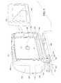
- FIGS. 2 and 3are perspective views of a first embodiment in accordance with the present invention.
- FIGS. 4 , 5 and 6are respectively an exploded view, a perspective view with the inductive charging system retracted and a perspective view with the inductive charging system extended in accordance with yet another embodiment in accordance with the present invention.
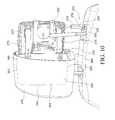
- FIGS. 7 , 8 , 9 and 10are respectively a perspective view and a partial cross sectional view thereof, and a perspective view and a partial cross sectional view thereof showing another embodiment in accordance with the present invention.
- a mobile entertainment system 10 for use in automobilesis disclosed.
- the present mobile entertainment system 10is particularly adapted and disclosed herein for use in conjunction with automobiles 20
- the present entertainment system 10may be utilized in conjunction with a wide variety of vehicles, for example, but not limited to, boats, aircrafts, etc., without departing from the spirit of the present invention.
- the centerpiece of the present mobile entertainment system 10is a video system 12 designed for reducing energy consumption.
- the reduced energy consumption of the present mobile entertainment system 10allows for implementation thereof without the need for a direct wired connection to the power system of an automobile.
- the power consumption of the video systemis preferably less than approximately 2 Amps, more preferably less than approximately 1.5 Amps, and even more preferably less than approximately 0.5 Amps.
- the video system 12generally includes a housing 14 in which a monitor 16 is mounted for viewing by those utilizing the present mobile entertainment system 10 .
- Media content for display upon the monitor 16is wirelessly transmitted to the video system 12 via a media storage unit 18 mounted within the automobile 20 , and discussed below in greater detail.
- the audio contentit is also wirelessly transmitted to the video system 12 for transmission to the user via speakers 22 built into the housing 14 of the video system 12 or via wired/wireless headphones linked to the video system 12 .
- the audio contentmay be transmitted to the automobile speakers.
- Such an arrangementcould be employed by directly wiring the media storage unit 18 to the automobile audio system or wirelessly linking the media storage unit 18 to the automobile audio system.
- the video system 12is provided with a wireless connection member, for example, a WiFi adapter allowing for transmission of media content between the media storage unit 18 and the video system 12 .
- the video system 12is also provided with electronic components necessary for processing the media content retrieved from the media storage unit 18 for display upon the monitor 16 and play through the speakers/headphones.
- the video system 12is also preferably provided with touch screen functionality allowing for ease of use without the need for additional buttons and control mechanisms.
- a battery 24is provided for powering the present video system 12 .
- the battery 24is designed for continual recharging via proximity charging, or inductive coupling or charging of the video system 12 , in particular, the battery 24 of the video system 12 which ultimately powers the video system 12 .
- inductive couplingrefers to the transfer of energy from one circuit component to another through a shared magnetic field. A change in current flow through one device induces current flow in the other device.
- the two devicesmay be physically contained in a single unit, as in the primary and secondary sides of a transformer, or may be separated as in the antennas on a transmitter and a receiver.
- Inductive couplingfavors low frequency energy sources.
- High frequency energy sourcesgenerally use capacitive coupling.
- a systemsuch as that disclosed in U.S. Pat. No. 7,118,240, which is incorporated herein by reference, is employed.
- poweris wirelessly transferred from a primary coil (or simply “primary”) 26 , which is powered by the electrical system of the automobile 20 to a secondary coil (or simply “secondary”) 28 in a secondary circuit housed in and electrically linked to the battery 24 of the video system 12 .
- the primary coil 26 of the power supply circuitis supported within a structural element of the automobile 20 , for example, within an upper edge 74 of a seat back 72 in a position adjacent to the headrest 30 in which the video system is mounted, as discussed below in accordance with preferred embodiments of the present invention.
- the secondary coil 28 of the secondary circuitis mounted within the video system 12 and is electrically coupled with the battery 24 and other operating components of the video system 12 to provide the power necessary for operating the video system 12 in accordance with the present invention.
- the wireless connectionprovides a number of advantages over conventional hardwired connections. The wireless connection reduces the chance of shock and provides a relatively high level of electrical isolation between the power supply circuit and the secondary circuit of the video system 12 . Inductive coupling also makes it easier for a consumer to replace limited-life components.
- the monitor 16is preferably an organic LED.
- an organic light-emitting diodeOLED
- LEPLight Emitting Polymer
- OELOrganic Electro-Luminescence
- LEDany light-emitting diode (LED) whose emissive electroluminescent layer is composed of a film of organic compounds.
- the layerusually contains a polymer substance that allows suitable organic compounds to be deposited. They are deposited in rows and columns onto a flat carrier by a simple “printing” process. The resulting matrix of pixels can emit light of different colors.
- OLED displaysdo not require a backlight to function and consequently draw far less power and, when powered from a battery, can operate longer on the same charge. Because there is no need to distribute the backlight, the OLED monitor utilized in accordance with a preferred embodiment of the present invention can also be much thinner than traditional LCD panels.
- the OLED monitor 16is composed of an emissive layer, a conductive layer, a substrate, and anode and cathode terminals.
- the layersare made of special organic polymer molecules that conduct electricity. Their levels of conductivity range from those of insulators to those of conductors, and so they are called organic semiconductors.
- a voltageis applied across the OLED monitor 16 such that the anode is positive with respect to the cathode. This causes a current of electrons to flow through the OLED monitor from cathode to anode.
- the cathodegives electrons to the emissive layer and the anode withdraws electrons from the conductive layer; in other words, the anode gives electron holes to the conductive layer.
- the emissive layerbecomes negatively charged, while the conductive layer becomes rich in positively charged holes. Electrostatic forces bring the electrons and the holes towards each other and recombine. This happens closer to the emissive layer, because in organic semiconductors holes are more mobile than electrons (unlike in inorganic semiconductors). The recombination causes a drop in the energy levels of electrons, accompanied by an emission of radiation whose frequency is in the visible region. That is why this layer is called emissive.
- Indium tin oxideis commonly used as the anode material. It is transparent to visible light and has a high work function which promotes injection of holes into the polymer layer. Metals such as aluminium and calcium are often used for the cathode as they have low work functions which promote injection of electrons into the polymer layer.
- OLEDcan be categorized into passive-matric OLED and active-matrix OLED.
- Active-matrix OLEDrequires a TFT backplane to switch ON/OFF the pixel and can make higher resolution and larger size display happen.
- OLEDsenable a greater range of colors, brightness, and viewing angle than LCDs, because OLED pixels directly emit light. OLED pixel colors appear correct and unshifted, even as the viewing angle approaches 90 degrees from normal. LCDs use a backlight and cannot show true black, while an “off” OLED element produces no light and consumes no power. Energy is also wasted in LCDs because they require polarizers which filter out about half of the light emitted by the backlight. Additionally, color filters in color LCDs filter out two-thirds of the light. OLEDs also have a faster response time than standard LCD screens. Whereas a standard LCD currently has an average of 8-12 millisecond response time, an OLED can have less than 0.01 millisecond response time.
- the media content for display upon the video systemis not actually stored upon the video system 12 itself, but is rather stored within the media storage unit 18 and transmitted to the video system 12 via wireless transmission protocols known to those skilled in the art.
- the present mobile entertainment system 10permits retrieval of audio and video media content from a remote library 34 .
- the video system 12include a media source 36 .
- the media source 36is housed within the housing 14 of the video system 12 .
- the media source 36includes data processing capabilities allowing for the streaming of media content for display upon the video system 12 as desired by a user.
- a wireless global communication network access point 38is mounted within the automobile 20 and is preferably integrated with the media storage unit 18 .
- the media source 36includes wireless communication capabilities permitting communication with the wireless global communication network access point 38 and media storage unit 18 for retrieval of video and audio content for display upon the video monitor 16 and speakers/headphones of the video system 12 .
- a remote library 34 of audio and video media contentis in wireless communication with the media storage unit 18 (and ultimately the media source 36 ) via the network access point 38 .
- the remote library 34includes storage space 39 for uploading of media content from a personal collection of audio and video media content 41 stored, for example, on a home computer linked to the remote library 34 via the Internet.
- the uploaded personal collection of audio and video media content 41 from a user for subsequent transmission to the media storage unit 18 upon synchronization of the remote library 34 with the media storage unit 18thereby provides the user with access to a personal collection of audio and video media content 41 .
- An access approval codeis associated with the media storage unit 18 instructing the remote library 34 to synchronize the personal collection of audio and video media content 41 with the media storage unit 18 as desired by the user.
- the media source 36may retrieve media content from the media storage unit 18 for presentation upon the video system 12 .
- the media source 36includes a storage medium upon which audio and video media content is stored, at least temporarily, for display upon the video monitor 16 of the video system 12 as desired by a user.
- the media source 36is a flash memory device upon which both audio and video content, as well as other viewable content, may be readily stored.
- the media source 36may take a variety of forms as technology moves forward, without departing from the spirit of the present invention.
- the video system 12may also be provided with a DVD player or other similar media player allowing the operator to play videos when those available via the media source described above are not desired.
- the wireless global communication network access point 38is mounted within the automobile 20 and is coupled to the media storage unit 18 , which is in wireless communication with the media source 36 for the transfer of data therebetween.
- the wireless connection between the media source 36 and the media storage unit 18may be achieved by various known protocols, for example, but not limited to WiFi. While a wireless connection between the network access point 38 and the media source 36 is disclosed in accordance with a preferred embodiment of the present invention, it is possible the utilization of a conventional wired connection might be more appropriate under certain circumstances and the use thereof would certainly fall within the spirit of the present invention. As storage capacity also increases, it is contemplated it may be possible to hold all of the media content within the video system 12 , that is, the media source 36 of the video system 12 . As such, and considering this possibility, the media storage unit 18 would be obsolete and the media source 36 would directly, and preferably wirelessly, communicate with the network access point 38 .
- the wireless global communication network access point 38provides users with access to a global communication network, for example, the Internet 40 , for access to a variety of data sources in a real time, high-speed manner.
- the wireless global communication network 40allows the media storage unit 18 , to which it is connected via the wireless global communication network access point 38 , to synchronize with the remote library 34 .
- the media storage unit 18includes wired or wireless communication capabilities permitting communication with the wireless global communication network access point 38 for retrieval of audio and video media content from the remote library 34 for display upon the video monitor 16 of the video system 12 .
- the media storage unit 18downloads information from the operator's personal collection of audio and video media content 41 or from a secure media source containing selected content maintained on the remote library 34 for storage therein and display upon the video monitor.
- a remote library 34 of audio and video media contentis in wireless communication with the media storage unit 18 via the wireless global communication network access point 38 .
- the remote library 34includes storage space 39 for uploading of media content from a personal collection of audio and video media content 41 from a user for subsequent transmission to the media storage unit 18 upon synchronization of the remote library 34 with the media storage unit 18 thereby providing the user with access to a personal collection of audio and video media content 41 .
- an access approval codeis associated with the media storage unit 18 instructing the remote library 34 to synchronize the audio and video media content with the media storage unit 18 as desired by the user.
- the media storage unit 18will communicate with the remote library 34 via the network access point 38 to ascertain whether additional audio or video content is available. If it is determined audio or video content is available for downloading, the content will either be downloaded to the media storage unit 18 automatically or the user will be provided with a prompt asking whether he or she wishes to have the audio and/or video content download to the media storage unit 18 for transmission to the media source 36 for viewing upon the monitor 16 .
- the remote library 34 of audio and video contentmay also provide the operator with access to selected content 43 he or she subscribes to through a predetermined subscription arrangement.
- the operatormay be provided with access to a certain level of video content (for example, old documentaries) through the provision of one subscription fee or the operator may be provided with access to another level of video content (for example, first run movies) through the provision of another subscription fee.
- media contentwill not be permanently stored upon the video system and the media source will only facilitate the streaming of data between the media storage unit and the video system, it may desirable for some applications to allow storage of a substantial amount of media directly upon the video system.
- the video systemmay further be provided with a large flash drive, hard drive or other data storage device which the criteria upon which the present invention is based permits.
- the video system 12 in accordance with the present inventionis fully portable and may be carried from one location to another location. However, when the video system 12 is utilized with an automobile it will be important for the safety of all traveling within the automobile that the video system is securely supported within the automobile 20 .
- a supporting structure 42is provided for selectively supporting the video system 12 within the automobile 20 .
- the supporting structure 42is composed of a drawer 44 integrally formed with the headrest 30 .
- the drawer 44includes a base support 46 integrated within the headrest body 48 and a drawer member 50 that selectively moves from a closed/use position (see FIG. 2 ) within the base support 46 such that the entire drawer 44 is substantially flush with the rear surface 52 of the headrest 30 and an open/exchange position (see FIG. 3 ) where the drawer member 50 is withdrawn from the base support 46 for selective insertion of the video system 12 within the drawer 44 , and ultimately within the headrest 30 .
- the base support 46is substantially rectangular and defines a central recess 54 shaped and dimensioned to receive the drawer member 50 and the video system 12 .
- the drawer member 50includes a transparent front wall 56 from which first, second and third sidewalls 58 , 60 , 62 extend for positioning within the recess 54 of the base support 46 .
- the first, second and third sidewalls 58 , 60 , 62are respectively positioned along the left side, bottom and right side of the front wall 56 leaving an insertion slot 64 along the top of the drawer member 50 that is shaped and dimensioned for receipt of the video system 12 .
- Each of the first sidewall 58 , second sidewall 60 and third sidewall 62includes an alignment member 58 a , 60 a , 62 a extending therefrom.
- the alignment members 58 a , 60 a , 62 aare shaped and dimensioned to guide the video system 12 as it is inserted within the drawer 44 .
- Movement of the drawer member 50 relative to the base support 46is controlled by a servomotor 66 that selectively moves the drawer member 50 between its closed position and its open position. Actuation of the servomotor 66 is preferably controlled by a switch 68 mounted on the headrest 30 .
- a servomotoris disclosed in accordance with a preferred embodiment of the present invention, it is contemplated alternative automated and manual movement mechanisms may be utilized without departing from the spirit of the present invention.
- the switch 68is actuated to move the drawer member 50 to its open position exposing the insertion slot 64 for slipping the video system 12 within the drawer 44 .
- the video system 12is inserted within the drawer 44 such that the monitor 16 thereof is facing the transparent front wall 56 of the drawer member 50 for viewing by a passenger sitting within the rear seat of the automobile 20 .
- the switch 68is actuated again causing the drawer member 50 to move to its closed position.
- Poweris supplied to the video system 12 by providing an electrical connection 69 within the drawer 44 that links with video system 12 for transmitting power to the secondary coil 28 and battery 24 of the video system 12 via the inductive charging system 70 which links the primary coil 26 within the seat back 72 positioned at the upper edge 74 of the seat back 72 to the secondary coil 28 within the video system 12 .
- the drawer 44is provided with a telescoping coupling member 76 that electrically links the secondary coil 28 of the video system 12 with the primary coil 26 .
- the telescoping coupling member 76is composed of a selectively telescoping arm 78 through which an electrical wire 80 extends for linking the distal end 82 of the telescoping arm 78 to the secondary coil 28 of the video system 12 .
- the distal end 82 of the telescoping arm 78is magnetically charged for attraction to a magnetically charged shroud 84 of the primary coil 26 .
- a latch mechanism 86 associated with the telescoping arm 78is released in a manner allowing the telescoping arm 78 to move toward the primary coil 26 improving the efficiency of the inductive coupling between the secondary coil 28 of the video system 12 and the primary coil 26 within the seat back 72 .
- the telescoping arm 78is pushed up into a recess 88 formed along the bottom 90 of the headrest 30 with the latch mechanism 86 holding it in this position.
- the video system 112is not removable from the headrest 130 , but is rather formed as part of a slip cover 142 shaped and dimensioned to fit over the headrest 130 with the video monitor 116 facing rearwardly for viewing by automobile passengers sitting within the rear seat of the automobile 120 .
- the slipcover 142is composed of a fabric base structure 144 shaped and dimensioned to fit over the headrest 130 .
- the fabric base structure 144includes a front wall 148 , first and second sidewalls 149 , 150 , a rear wall 152 , and a bottom wall 154 .
- the bottom wall 154 of the fabric base structure 144is provided with a zipper 156 allowing for expansion and closure of the bottom wall 154 to allow the fabric base structure 144 to fit over the headrest 130 .
- a video monitor 116is mounted along the rear wall 152 of the fabric base structure 144 for pivotal movement allowing adjustment for viewing by a passenger sitting in a rear seat of the automobile 120 .
- the electronic components relating to the powering and functioning of the video monitorare mounted within fabric base structure 144 .
- poweris supplied to the video system 112 by providing an electrical connection 169 within slip cover 142 that links with video system 112 for transmitting power to the video system 112 via the inductive charging system 170 which links the primary coil 126 within the seat back 172 positioned at the upper edge 174 of the seat back 172 to the secondary coil 128 within the video system 112 .
- the bottom wall 154is provided with a telescoping coupling member 176 that electrically links the secondary coil 128 of the video system 112 with the primary coil 126 .
- the telescoping coupling member 176is composed of a selectively telescoping arm 178 through which an electrical wire 180 extends for linking the distal end 182 of the telescoping arm 178 to the secondary coil 128 of the video system 112 .
- the distal end 182 of the telescoping arm 178is magnetically charged for attraction to a magnetically charged shroud 184 of the primary coil 126 .
- a latch mechanism 186 associated with the telescoping arm 178is released in a manner allowing the telescoping arm 178 to move toward the primary coil 126 improving the efficiency of the inductive coupling between the secondary coil 128 of the video system 112 and the primary coil 126 within the seat back 172 .
- the telescoping arm 178is pushed up into a recess 188 formed along the bottom wall 154 of the fabric base structure 144 of the headrest 130 with the latch mechanism 186 holding it in this position.
- a snap fit mechanism 242is implemented for selective mounting of the video system 212 within the headrest 230 . More particularly, and with reference to FIGS. 7 to 10 , the snap fit mechanism 242 includes a recessed support structure 244 into which the video system 212 is snap fit in accordance with the present invention.
- the recessed support structure 244includes a base support 246 that is fit within a recess formed in a headrest 230 .
- the recessed support structure 244includes a closed base wall 248 , first, second, third, and fourth sidewalls 250 , 252 , 254 , 256 extending from a perimeter edge of the closed base wall 248 , and an open top 258 shaped and dimensioned for receipt of a video system 212 in accordance with a preferred embodiment and as discussed below in greater detail.
- a false front wall 260is supported within the recessed support structure 244 for movement from a recessed position adjacent the closed base wall 248 (see FIGS. 9 and 10 ) to an exposed position covering the open top 258 when the device is not in use (see FIGS. 7 and 8 ). As such, the false front wall 260 is maintained in an orientation such that the plane in which the false front wall 260 lies is substantially parallel to the plane in which the closed base wall 248 lies.
- Controlled movement of the false front wall 260is facilitated by sliding spring arms 272 that extend between the closed base wall 248 and the rear surface 270 of the false front wall 260 .
- the sliding spring arms 272are biased to force the false front wall 260 to its exposed position as shown with reference to FIGS. 7 and 8 .
- the bias of the sliding spring arms 272is overcome and the false front wall 260 is moved to its recessed positioned as shown in FIGS. 9 and 10 .
- the spring biased nature of the false front wall 260allows a user to move the false front wall 260 from its exposed position to its recessed position by simply applying a slight force to the false front wall 260 toward its recessed position and forcing it toward the closed base wall 248 .
- latches 262 within the recessed support structure 244extend between the false front wall 260 and the base support 246 to hold the false front wall 260 in its recessed position.
- Actuation of the latches 262is achieved by a central button 264 positioned along the false front wall 260 that upon pressing releases the latches 262 to allow movement of the false front wall 260 .
- the latches 262securely hold the false front wall 260 in its exposed position until such a time that a user wishes to move it inwardly toward its recessed position.
- the cavity 266 defined by the base support 246is available for receiving the video system 212 in accordance with the present invention.
- the video system 212is simply slipped into the cavity 266 and held in position by conventional coupling mechanisms. Removal of the video system 212 is achieved by simply reversing the steps outlined above.
- poweris supplied to the video system by providing an electrical connection within recessed support structure 244 that links with video system 212 for transmitting power to the video system 212 via the inductive charging system 270 which links the primary coil 226 within the seat back 272 positioned at the upper edge 274 of the seat back 272 to the secondary coil 228 within the video system 212 .
- the bottom of the headrest 230is provided with a telescoping coupling member 276 that electrically links the secondary coil 228 of the video system 212 with the primary coil 226 .
- the telescoping coupling member 276is composed of a selectively telescoping arm 278 through which an electrical wire 280 extends for linking the distal end 282 of the telescoping arm 278 to the secondary coil 228 of the video system 212 .
- an electrical wire 280extends for linking the distal end 282 of the telescoping arm 278 to the secondary coil 228 of the video system 212 .
- the distal end 282 of the telescoping arm 278is magnetically charged for attraction to a magnetically charged shroud 284 of the primary coil 226 .
- a latch mechanism 286 associated with the telescoping arm 278is released in a manner allowing the telescoping arm 278 to move toward the primary coil 226 improving the efficiency of the inductive coupling between the secondary coil 228 of the video system 212 and the primary coil 226 within the seat back 272 .
- the telescoping arm 278is pushed up into a recess 288 formed along the bottom wall 290 of the headrest 230 with the latch mechanism 286 holding it in this position.
Landscapes
- Engineering & Computer Science (AREA)
- Mechanical Engineering (AREA)
- Transportation (AREA)
- Chemical & Material Sciences (AREA)
- Combustion & Propulsion (AREA)
- Aviation & Aerospace Engineering (AREA)
- Fittings On The Vehicle Exterior For Carrying Loads, And Devices For Holding Or Mounting Articles (AREA)
Abstract
Description
Claims (22)
Priority Applications (1)
| Application Number | Priority Date | Filing Date | Title |
|---|---|---|---|
| US12/216,852US8203657B2 (en) | 2008-07-11 | 2008-07-11 | Inductively powered mobile entertainment system |
Applications Claiming Priority (1)
| Application Number | Priority Date | Filing Date | Title |
|---|---|---|---|
| US12/216,852US8203657B2 (en) | 2008-07-11 | 2008-07-11 | Inductively powered mobile entertainment system |
Publications (2)
| Publication Number | Publication Date |
|---|---|
| US20100007805A1 US20100007805A1 (en) | 2010-01-14 |
| US8203657B2true US8203657B2 (en) | 2012-06-19 |
Family
ID=41504832
Family Applications (1)
| Application Number | Title | Priority Date | Filing Date |
|---|---|---|---|
| US12/216,852Expired - Fee RelatedUS8203657B2 (en) | 2008-07-11 | 2008-07-11 | Inductively powered mobile entertainment system |
Country Status (1)
| Country | Link |
|---|---|
| US (1) | US8203657B2 (en) |
Cited By (22)
| Publication number | Priority date | Publication date | Assignee | Title |
|---|---|---|---|---|
| US20120139307A1 (en)* | 2010-12-07 | 2012-06-07 | Rik Westerink | Modular display assembly |
| US20120205951A1 (en)* | 2009-11-10 | 2012-08-16 | Johanna Strolka-Echols | Electric Outdoor Lounge Chair |
| US20130106164A1 (en)* | 2011-10-31 | 2013-05-02 | L&P Property Management Company | Removable control mechanism for use in upholstered furniture |
| US8585140B2 (en) | 2002-08-14 | 2013-11-19 | Chung L. Chang | Headrest-mounted monitor |
| US20140084648A1 (en)* | 2011-10-14 | 2014-03-27 | Michael Tai-Hao Wen | Vehicle display system |
| US20140209648A1 (en)* | 2013-01-29 | 2014-07-31 | Airbus Operations Gmbh | Holding Arrangement For A Mobile Device, Passenger Seat With A Holding Arrangement For A Mobile Device And Vehicle |
| US8893193B2 (en) | 2002-10-28 | 2014-11-18 | Johnson Safety, Inc. | Mobile video system |
| US9004588B2 (en) | 2005-11-02 | 2015-04-14 | Johnson Safety, Inc | Headrest-mounted entertainment systems |
| US20160023619A1 (en)* | 2010-12-14 | 2016-01-28 | Voxx International Corporation | Vehicle entertainment system |
| US9310020B1 (en) | 2013-09-17 | 2016-04-12 | Douglas B. Bernards | Mobile device mounting system and method |
| US9421892B1 (en)* | 2015-01-29 | 2016-08-23 | Toyota Motor Engineering & Manufacturing North America, Inc. | Headrest with retainer |
| US9617002B2 (en)* | 2012-06-25 | 2017-04-11 | Lufthansa Systems Ag | Seat for a vehicle and vehicle |
| US20170174146A1 (en)* | 2015-12-22 | 2017-06-22 | Brian L. Kipp | Adjustable mobile-device holder |
| US9912174B2 (en) | 2013-05-10 | 2018-03-06 | Cynetic Designs Ltd. | Inductively coupled wireless power and data for a garment via a dongle |
| US10314404B2 (en)* | 2014-09-25 | 2019-06-11 | King Furniture Australia Pty Ltd. | Article of furniture |
| US10406957B2 (en)* | 2017-04-11 | 2019-09-10 | Ford Global Technologies, Llc | Head restraint with hidden storage receptacles |
| US10717378B2 (en) | 2017-06-30 | 2020-07-21 | Faurecia Automotive Seating, Llc | Headrest for a vehicle seat |
| US10905810B2 (en) | 2018-02-21 | 2021-02-02 | Medtronic, Inc. | TETS recharged patient alert system for LVAD patients |
| US11014481B2 (en) | 2019-09-25 | 2021-05-25 | Faurecia Automotive Seating, Llc | Headrest for a vehicle seat |
| CN112977217A (en)* | 2019-12-18 | 2021-06-18 | 丰田自动车株式会社 | Vehicle seat and vehicle headrest |
| US11979048B2 (en) | 2020-09-18 | 2024-05-07 | B/E Aerospace, Inc. | Inductive charging device holder |
| DE102023114518B3 (en) | 2023-06-02 | 2024-05-29 | Dr. Ing. H.C. F. Porsche Aktiengesellschaft | Motor vehicle |
Families Citing this family (41)
| Publication number | Priority date | Publication date | Assignee | Title |
|---|---|---|---|---|
| US9813117B2 (en)* | 2011-06-21 | 2017-11-07 | Powermat Technologies Ltd. | In vehicle inductive power provision system and method |
| DE102011083626B4 (en)* | 2011-09-28 | 2023-05-25 | Airbus Operations Gmbh | Cover for a seat in an aircraft or spacecraft |
| DE102011083622A1 (en)* | 2011-09-28 | 2013-03-28 | Airbus Operations Gmbh | Seat with universal device for receiving an electronic device for an aircraft or spacecraft |
| WO2013126421A1 (en)* | 2012-02-20 | 2013-08-29 | Zodiac Seats Us Llc | Personal electronic device mounting structures |
| JP6245652B2 (en)* | 2012-10-11 | 2017-12-13 | 田原 博史 | Video observation system |
| FR2998411A1 (en) | 2012-11-19 | 2014-05-23 | Eurocopter France | WIRELESS ELECTRICAL POWER SUPPLY DEVICE INSTALLED INSIDE AN AIRCRAFT |
| DE102013200811A1 (en)* | 2013-01-18 | 2014-07-24 | Novero Dabendorf Gmbh | Holding device for a wirelessly coupleable terminal and method for producing a holding device |
| EP3129286B1 (en)* | 2014-04-07 | 2022-03-23 | Safran Seats USA LLC | Inductive power transmission in aircraft seats |
| DE102014207384A1 (en)* | 2014-04-17 | 2015-10-22 | Bayerische Motoren Werke Aktiengesellschaft | Device and system for electrical charging for a motor vehicle |
| DE102014211766A1 (en) | 2014-06-18 | 2016-01-07 | Airbus Operations Gmbh | Passenger seat with holding device for a media player |
| DE102015009746A1 (en)* | 2015-07-29 | 2017-02-02 | Audi Ag | Motor vehicle comprising at least one seat with a headrest |
| DE102015010328B4 (en)* | 2015-08-06 | 2020-09-17 | Audi Ag | Motor vehicle with a charging device for electronic data glasses |
| US9843853B2 (en) | 2015-08-29 | 2017-12-12 | Bragi GmbH | Power control for battery powered personal area network device system and method |
| US10104458B2 (en) | 2015-10-20 | 2018-10-16 | Bragi GmbH | Enhanced biometric control systems for detection of emergency events system and method |
| US9876385B2 (en)* | 2015-11-12 | 2018-01-23 | Ami Industries, Inc. | Seat wireless charger |
| US9944295B2 (en) | 2015-11-27 | 2018-04-17 | Bragi GmbH | Vehicle with wearable for identifying role of one or more users and adjustment of user settings |
| US10085082B2 (en) | 2016-03-11 | 2018-09-25 | Bragi GmbH | Earpiece with GPS receiver |
| US10045116B2 (en) | 2016-03-14 | 2018-08-07 | Bragi GmbH | Explosive sound pressure level active noise cancellation utilizing completely wireless earpieces system and method |
| US10052065B2 (en) | 2016-03-23 | 2018-08-21 | Bragi GmbH | Earpiece life monitor with capability of automatic notification system and method |
| US10075010B2 (en)* | 2016-03-30 | 2018-09-11 | Faraday & Future Inc. | Tablet connection system |
| US10201309B2 (en) | 2016-07-06 | 2019-02-12 | Bragi GmbH | Detection of physiological data using radar/lidar of wireless earpieces |
| US10045110B2 (en) | 2016-07-06 | 2018-08-07 | Bragi GmbH | Selective sound field environment processing system and method |
| US10062373B2 (en) | 2016-11-03 | 2018-08-28 | Bragi GmbH | Selective audio isolation from body generated sound system and method |
| US10045117B2 (en) | 2016-11-04 | 2018-08-07 | Bragi GmbH | Earpiece with modified ambient environment over-ride function |
| US10045112B2 (en) | 2016-11-04 | 2018-08-07 | Bragi GmbH | Earpiece with added ambient environment |
| US10058282B2 (en) | 2016-11-04 | 2018-08-28 | Bragi GmbH | Manual operation assistance with earpiece with 3D sound cues |
| US10063957B2 (en) | 2016-11-04 | 2018-08-28 | Bragi GmbH | Earpiece with source selection within ambient environment |
| CN107585314A (en)* | 2017-06-14 | 2018-01-16 | 林进发 | A kind of aircraft |
| CN107585312A (en)* | 2017-06-14 | 2018-01-16 | 林进发 | A kind of type aircraft equipment |
| US10384578B2 (en)* | 2017-07-21 | 2019-08-20 | Ford Global Technologies, Llc | Seat assembly visor |
| US10344960B2 (en) | 2017-09-19 | 2019-07-09 | Bragi GmbH | Wireless earpiece controlled medical headlight |
| US11272367B2 (en) | 2017-09-20 | 2022-03-08 | Bragi GmbH | Wireless earpieces for hub communications |
| US11220198B2 (en)* | 2018-03-07 | 2022-01-11 | Lascelles Cotterell | Headrest cover holder system |
| US11213130B2 (en)* | 2018-03-07 | 2022-01-04 | Lascelles Cotterell | Headrest cover holder system |
| US20190276150A1 (en)* | 2018-03-07 | 2019-09-12 | Lascelles Cotterell | Headrest cover holder system |
| US11029548B2 (en)* | 2019-09-13 | 2021-06-08 | Panasonic Avionics Corporation | In-flight entertainment systems and monitor assemblies for in-flight entertainment systems |
| CN113443147A (en)* | 2020-03-24 | 2021-09-28 | 空中客车(中国)企业管理服务有限公司 | Integrated aircraft passenger entertainment device, aircraft passenger seat and aircraft |
| JP7512773B2 (en)* | 2020-08-31 | 2024-07-09 | 株式会社オートネットワーク技術研究所 | Power supply structure for headrest |
| US11820296B2 (en)* | 2021-07-16 | 2023-11-21 | Havis, Inc. | Push-button actuated rear latch hook mechanism |
| KR20240050333A (en) | 2021-08-24 | 2024-04-18 | 시티에스 코포레이션 | vehicle seat connector assembly |
| US11991218B2 (en)* | 2021-12-28 | 2024-05-21 | Rivian Ip Holdings, Llc | Systems and methods for providing media content during vehicle charging and servicing |
Citations (115)
| Publication number | Priority date | Publication date | Assignee | Title |
|---|---|---|---|---|
| US2652101A (en)* | 1952-01-14 | 1953-09-15 | Samsky Abraham | Adjustable headrest |
| US3511535A (en)* | 1968-04-24 | 1970-05-12 | Gen Motors Corp | Adjustable headrest support assembly |
| US3964788A (en)* | 1974-07-03 | 1976-06-22 | Joseph Kmetyko | Headrest for vehicles |
| US4490842A (en)* | 1981-05-22 | 1984-12-25 | Clarion Co., Ltd. | Headrest speaker device |
| DE29518369U1 (en) | 1995-11-18 | 1996-01-18 | Schlechtweg, Hartmut, 75446 Wiernsheim | Headrests for vehicle seats |
| US6092705A (en)* | 1998-08-03 | 2000-07-25 | Meritt; Ronald R. | Self-contained case for housing transporting and mounting video monitor and video player for use in passenger vehicles |
| US6216927B1 (en)* | 1998-08-03 | 2001-04-17 | Ronald Meritt | Mounting system for releasably and securely mounting an entertainment accessory within an automobile |
| US6217118B1 (en)* | 1997-06-16 | 2001-04-17 | Trw Occupant Restraint Systems Gmbh & Co. Kg | Car seat with displaceable head rest |
| US20010008266A1 (en) | 2000-01-15 | 2001-07-19 | Lambert Graham Keith | In-car video systems |
| US20010037360A1 (en) | 2000-05-12 | 2001-11-01 | Koninklijke Philips Electronics N.V. | Data service at a transit terminal |
| US20020095680A1 (en) | 2001-01-12 | 2002-07-18 | Davidson Robert J. | Personal movie storage module |
| US6424055B1 (en)* | 1998-10-14 | 2002-07-23 | Robert Bosch Gmbh | Device for transmitting signals to one or more circuits integrated into the head rest of a motor vehicle seat |
| US6443574B1 (en) | 2001-07-24 | 2002-09-03 | Visteon Global Technologies, Inc. | Removable vehicle entertainment system |
| WO2002073574A1 (en) | 2001-03-14 | 2002-09-19 | Claremont Office Interiors Ltd | Advertising device |
| US20020135974A1 (en) | 2001-03-22 | 2002-09-26 | Bell Cynthia S. | Docking digital picture displays |
| US20020174269A1 (en) | 2001-05-16 | 2002-11-21 | Fullaudio Corporation | Proximity synchronizing audio gateway device |
| US6567660B1 (en) | 2000-08-01 | 2003-05-20 | Command Audio Corporation | On-demand information service using wireless cellular communications system |
| US20030110057A1 (en) | 2001-12-06 | 2003-06-12 | Toyota Motor Sales, U.S.A., Inc. | Vehicle player system |
| US20030137584A1 (en) | 2001-10-29 | 2003-07-24 | Gene Norvell | Detachable vehicle monitor |
| US6606481B1 (en) | 1997-06-05 | 2003-08-12 | Telia Ab | System at telecommunications network |
| US20040002359A1 (en) | 2002-06-27 | 2004-01-01 | Deas David A. | Information filling station facilitating wireless transfer of data content to a portable device or other pre-defined locations |
| US20040004378A1 (en)* | 2002-07-02 | 2004-01-08 | Eric Park | Headrest mounted video display |
| US6694200B1 (en) | 1999-04-13 | 2004-02-17 | Digital5, Inc. | Hard disk based portable device |
| US20040032543A1 (en)* | 2002-08-14 | 2004-02-19 | Chang Chung L. | Headrest-mounted monitor |
| US20040061995A1 (en) | 2002-09-28 | 2004-04-01 | Mcmahon Edward L. | Portable computer docking station for vehicles |
| US20040086259A1 (en) | 2002-11-04 | 2004-05-06 | Audiovox Corporation | Hood for vehicle seat headrest including a video system |
| US6742185B1 (en)* | 2003-03-27 | 2004-05-25 | Visteon Global Technologies, Inc. | Video screen module endcap wireless signal transmitter |
| US20040130616A1 (en) | 2003-01-03 | 2004-07-08 | Thomas Tseng | Flip-open screen with audio/video player |
| US20040133923A1 (en) | 2002-08-21 | 2004-07-08 | Watson Scott F. | Digital home movie library |
| US6768523B2 (en)* | 2001-02-15 | 2004-07-27 | Quanta Computer, Inc. | Slidably detachable mobile phone display unit |
| US20040189797A1 (en) | 2003-03-31 | 2004-09-30 | Todd Neal Jonathan | Console lid family entertainment system |
| US20040212957A1 (en) | 2003-04-25 | 2004-10-28 | Audiovox Corporation | Portable video system |
| US20040227861A1 (en) | 2003-05-15 | 2004-11-18 | Schedivy George C. | Video display system |
| US20040228622A1 (en) | 2003-05-15 | 2004-11-18 | Audiovox Corporation | Portable video system |
| US20040233374A1 (en)* | 2003-03-07 | 2004-11-25 | Semiconductor Energy Laboratory Co., Ltd. | Liquid crystal display device and method for manufacturing the same |
| US6824917B2 (en)* | 2001-12-11 | 2004-11-30 | Nokia Corporation | Battery system for a portable electronic device |
| US20040266336A1 (en) | 2003-04-25 | 2004-12-30 | Stelios Patsiokas | System and method for providing recording and playback of digital media content |
| US20050005298A1 (en) | 2000-10-27 | 2005-01-06 | Audiovox Corporation | Vehicle console capable of wireless reception and transmission of audio and video data |
| US20050007067A1 (en)* | 1999-06-21 | 2005-01-13 | Baarman David W. | Vehicle interface |
| US20050044564A1 (en) | 2003-06-04 | 2005-02-24 | Matsushita Avionics Systems Corporation | System and method for downloading files |
| US20050052046A1 (en) | 2003-05-15 | 2005-03-10 | Audiovox Corporation | Seat mountable entertainment system |
| US6871356B2 (en)* | 2002-10-28 | 2005-03-22 | Johnson Safety, Inc. | Mobile video system |
| US20050071375A1 (en) | 2003-09-30 | 2005-03-31 | Phil Houghton | Wireless media player |
| US20050075783A1 (en) | 2003-07-24 | 2005-04-07 | Stefan Wolf | System for providing data in a mobile device |
| US6883870B2 (en)* | 2001-03-21 | 2005-04-26 | Security Vision Concept | Head rest, particularly for a motor vehicle seat |
| US20050099548A1 (en)* | 2003-11-07 | 2005-05-12 | Vitito Christopher J. | Automobile entertainment system |
| US20050110913A1 (en)* | 2003-11-07 | 2005-05-26 | Vitito Christopher J. | Automobile entertainment system |
| US6899365B2 (en) | 2003-05-15 | 2005-05-31 | Audiovox Corporation | Seat mountable entertainment system |
| US20050116943A1 (en) | 2003-08-28 | 2005-06-02 | Philipp Wohrle | Vehicle visual display system |
| US20050120380A1 (en) | 2003-09-03 | 2005-06-02 | Digital Networks North America, Inc. | Portable entertainment apparatus |
| US20050127869A1 (en)* | 2003-12-12 | 2005-06-16 | Microsoft Corporation | Inductive power adapter |
| US20050130586A1 (en) | 2003-11-14 | 2005-06-16 | Cingular Wireless Ii, Llc | Personal base station system with wireless video capability |
| DE202005007826U1 (en)* | 2005-05-19 | 2005-07-14 | Keiper Gmbh & Co. Kg | Linkage system for a motor vehicle's seat/head restraint structure has a connector attachment element inserted into a lining element with links set in place in pairs to produce an electrical contact |
| US20050166238A1 (en)* | 2004-01-08 | 2005-07-28 | Vitito Christopher J. | Automobile entertainment system |
| US20050216938A1 (en) | 2002-05-14 | 2005-09-29 | Thales Avionics, Inc. | In-flight entertainment system with wireless communication among components |
| US20050227773A1 (en) | 2003-09-24 | 2005-10-13 | Lu Priscilla M | Portable video storage and playback device |
| US20050258806A1 (en) | 2004-02-28 | 2005-11-24 | Universal Electronics Inc. | System and method for automatically synchronizing and acquiring content for battery powered devices |
| US20050264051A1 (en)* | 2004-05-26 | 2005-12-01 | Lawall Jennifer P | Occupant detecting seat assembly with headrest and method of moving headrest |
| US6973476B1 (en) | 2000-03-10 | 2005-12-06 | Atheros Communications | System and method for communicating data via a wireless high speed link |
| US20060045015A1 (en) | 2004-08-31 | 2006-03-02 | Axel Nix | System and method for wireless broadcast of multimedia files to vehicles |
| US20060070103A1 (en) | 2003-11-07 | 2006-03-30 | Vitito Christopher J | Vehicle entertainment system |
| US20060074550A1 (en) | 2004-09-20 | 2006-04-06 | Freer Carl J | System and method for distributing multimedia content via mobile wireless platforms |
| US20060098238A1 (en) | 2004-11-05 | 2006-05-11 | Nokia Corporation, Doing Business In Espoo, Finlan | On-demand activation of bluetooth sap |
| US20060107295A1 (en) | 2004-06-15 | 2006-05-18 | Panasonic Avionics Corporation | Portable media device and method for presenting viewing content during travel |
| US7050124B2 (en) | 2002-11-05 | 2006-05-23 | Samsung Electronics Co., Ltd. | Mobile video system |
| US20060109388A1 (en) | 1998-12-28 | 2006-05-25 | Johnson Controls Technology Company | Wireless signal system for a video display unit |
| US20060119151A1 (en) | 2003-11-07 | 2006-06-08 | Vitito Christopher J | Vehicle entertainment system |
| US7062254B2 (en) | 2000-02-23 | 2006-06-13 | Harman Becker Automotive Systems Gmbh | Method for operating a playback unit in a vehicle, for playing back data stored on a data medium |
| US20060130099A1 (en) | 2004-12-13 | 2006-06-15 | Rooyen Pieter V | Method and system for cellular network and integrated broadcast television (TV) downlink with intelligent service control without feedback |
| US20060138308A1 (en) | 2004-12-29 | 2006-06-29 | Davis J R | Vehicle entertainment system utilitzing portable media player |
| US20060148577A1 (en) | 2003-11-07 | 2006-07-06 | Vitito Christopher J | Automobile entertainment system |
| US7084932B1 (en)* | 1999-12-28 | 2006-08-01 | Johnson Controls Technology Company | Video display system for a vehicle |
| US20060181982A1 (en) | 2005-02-11 | 2006-08-17 | Villevieille Jean-Marc A | Wireless adaptor for content transfer |
| US20060184968A1 (en) | 2005-02-11 | 2006-08-17 | Clayton Richard M | Automatic content update for a target device |
| US7118240B2 (en) | 1999-06-21 | 2006-10-10 | Access Business Group International Llc | Inductively powered apparatus |
| US20070052266A1 (en)* | 2005-09-08 | 2007-03-08 | Fa-Yu Chu | Adjustable headrest bracket |
| US20070057541A1 (en)* | 2005-09-12 | 2007-03-15 | Fu-Ruei Huang | Angle-adjusting apparatus for a housing of headrest display |
| US20070070259A1 (en)* | 2005-09-16 | 2007-03-29 | Audiovox Corporation | Cover for a vehicle media device |
| US20070091215A1 (en)* | 2004-10-06 | 2007-04-26 | Takahiro Ikunami | Fold-down monitoring apparatus |
| US20070101372A1 (en)* | 2005-11-02 | 2007-05-03 | Chang Chung L | Headrest mounted entertainment system |
| US7239040B2 (en)* | 2003-07-25 | 2007-07-03 | Alpine Electronics, Inc. | Method and apparatus for releasing brake interlock function for vehicle audio/video display unit |
| US20070171316A1 (en)* | 1998-12-28 | 2007-07-26 | Johnson Controls Technology Company | Video display system for a vehicle |
| US20070182367A1 (en)* | 2006-01-31 | 2007-08-09 | Afshin Partovi | Inductive power source and charging system |
| US20070222248A1 (en)* | 2006-03-21 | 2007-09-27 | Be Aerospace, Inc. | Holster for portable ife device |
| US20070242172A1 (en)* | 2005-09-16 | 2007-10-18 | Jeff Macholz | Interchangeable switch assembly for media device |
| WO2007129029A2 (en) | 2006-05-10 | 2007-11-15 | Audiovox Incaar Systems Gmbh | Console |
| US20070290536A1 (en)* | 2006-06-20 | 2007-12-20 | Lear Corporation | Pop-up display |
| US20080036927A1 (en)* | 2006-08-10 | 2008-02-14 | Harman Becker Automotive Systems | Display system |
| US7352567B2 (en)* | 2005-08-09 | 2008-04-01 | Apple Inc. | Methods and apparatuses for docking a portable electronic device that has a planar like configuration and that operates in multiple orientations |
| US20080079388A1 (en)* | 2006-10-03 | 2008-04-03 | Visteon Global Technologies, Inc. | Wireless charging device |
| US7360833B2 (en)* | 2003-11-07 | 2008-04-22 | Vitito Christopher J | Vehicle entertainment system with backside loading DVD player |
| US20080100706A1 (en)* | 2002-06-11 | 2008-05-01 | Intelligent Technologies International, Inc. | Asset Monitoring System Using Multiple Imagers |
| US7375492B2 (en)* | 2003-12-12 | 2008-05-20 | Microsoft Corporation | Inductively charged battery pack |
| US20080157574A1 (en)* | 2006-12-27 | 2008-07-03 | Larussa Joseph J | Dockable media system |
| US20080170165A1 (en)* | 2007-01-16 | 2008-07-17 | Mark Lee | Reception Structure for Mobile Video and Audio Device |
| US7407227B1 (en)* | 2003-03-20 | 2008-08-05 | Timely Innovations, L.P. | Headrest having an integrated video screen |
| US20080252798A1 (en)* | 2003-11-07 | 2008-10-16 | Vitito Christopher J | Vehicle entertainment system |
| US7462951B1 (en)* | 2004-08-11 | 2008-12-09 | Access Business Group International Llc | Portable inductive power station |
| US20090085383A1 (en)* | 2007-10-01 | 2009-04-02 | Lear Corporation | Vehicle seat having an electronic display mounted thereon |
| US20090096413A1 (en)* | 2006-01-31 | 2009-04-16 | Mojo Mobility, Inc. | System and method for inductive charging of portable devices |
| US7560827B2 (en)* | 2006-10-31 | 2009-07-14 | Lear Corporation | Removable seat sensing system |
| US7597393B1 (en)* | 2003-04-04 | 2009-10-06 | Shanna Murphy, legal representative | Headrest/head restraint having an integrated video screen |
| US20100045790A1 (en)* | 2001-01-23 | 2010-02-25 | Donnelly Corporation | Video mirror system for vehicle |
| US20100060050A1 (en)* | 2007-03-23 | 2010-03-11 | Lufthansa Technik Ag | Wirelessly controllable electrical functional unit for an aircraft |
| US7679578B2 (en)* | 2003-05-15 | 2010-03-16 | Audiovox Corporation | Headrest mountable video system |
| US20100090491A1 (en)* | 2008-10-15 | 2010-04-15 | Johnson Controls Technology Company | Vehicle floor console |
| US7719408B2 (en)* | 2000-03-02 | 2010-05-18 | Donnelly Corporation | Mirror system for vehicle |
| US7728551B2 (en)* | 2007-04-26 | 2010-06-01 | Visteon Global Technologies, Inc. | Wireless power transfer system |
| US7758116B2 (en)* | 2007-02-23 | 2010-07-20 | Toyota Boshoku Kabushiki Kaisha | Monitor unit for a vehicle seat |
| US20100194336A1 (en)* | 2007-10-18 | 2010-08-05 | Powermat Ltd. | Inductively chargeable audio devices |
| US7780231B2 (en)* | 2003-05-15 | 2010-08-24 | Audiovox Corporation | Entertainment system mountable in a vehicle seat and methods for mounting and displaying same |
| US20110018498A1 (en)* | 2007-12-21 | 2011-01-27 | Soar Roger J | Vehicle seat inductive charger and data transmitter |
| US7909397B2 (en)* | 2003-05-15 | 2011-03-22 | Audiovox Corporation | In-vehicle docking station for a portable media player |
| US7948208B2 (en)* | 2006-06-01 | 2011-05-24 | Mojo Mobility, Inc. | Power source, charging system, and inductive receiver for mobile devices |
| US20110181796A1 (en)* | 2003-05-15 | 2011-07-28 | Audiovox Corporation | Entertainment system mountable in a vehicle and methods for mounting and displaying same |
- 2008
- 2008-07-11USUS12/216,852patent/US8203657B2/ennot_activeExpired - Fee Related
Patent Citations (124)
| Publication number | Priority date | Publication date | Assignee | Title |
|---|---|---|---|---|
| US2652101A (en)* | 1952-01-14 | 1953-09-15 | Samsky Abraham | Adjustable headrest |
| US3511535A (en)* | 1968-04-24 | 1970-05-12 | Gen Motors Corp | Adjustable headrest support assembly |
| US3964788A (en)* | 1974-07-03 | 1976-06-22 | Joseph Kmetyko | Headrest for vehicles |
| US4490842A (en)* | 1981-05-22 | 1984-12-25 | Clarion Co., Ltd. | Headrest speaker device |
| DE29518369U1 (en) | 1995-11-18 | 1996-01-18 | Schlechtweg, Hartmut, 75446 Wiernsheim | Headrests for vehicle seats |
| US6606481B1 (en) | 1997-06-05 | 2003-08-12 | Telia Ab | System at telecommunications network |
| US6217118B1 (en)* | 1997-06-16 | 2001-04-17 | Trw Occupant Restraint Systems Gmbh & Co. Kg | Car seat with displaceable head rest |
| US20010000419A1 (en)* | 1997-06-16 | 2001-04-26 | Gmbh & Co. Kg | Vehicle seat with displaceable headrest |
| US6092705A (en)* | 1998-08-03 | 2000-07-25 | Meritt; Ronald R. | Self-contained case for housing transporting and mounting video monitor and video player for use in passenger vehicles |
| US6216927B1 (en)* | 1998-08-03 | 2001-04-17 | Ronald Meritt | Mounting system for releasably and securely mounting an entertainment accessory within an automobile |
| US6424055B1 (en)* | 1998-10-14 | 2002-07-23 | Robert Bosch Gmbh | Device for transmitting signals to one or more circuits integrated into the head rest of a motor vehicle seat |
| US20070171316A1 (en)* | 1998-12-28 | 2007-07-26 | Johnson Controls Technology Company | Video display system for a vehicle |
| US20060109388A1 (en) | 1998-12-28 | 2006-05-25 | Johnson Controls Technology Company | Wireless signal system for a video display unit |
| US6694200B1 (en) | 1999-04-13 | 2004-02-17 | Digital5, Inc. | Hard disk based portable device |
| US7118240B2 (en) | 1999-06-21 | 2006-10-10 | Access Business Group International Llc | Inductively powered apparatus |
| US20050007067A1 (en)* | 1999-06-21 | 2005-01-13 | Baarman David W. | Vehicle interface |
| US7612528B2 (en)* | 1999-06-21 | 2009-11-03 | Access Business Group International Llc | Vehicle interface |
| US7084932B1 (en)* | 1999-12-28 | 2006-08-01 | Johnson Controls Technology Company | Video display system for a vehicle |
| US6619605B2 (en) | 2000-01-15 | 2003-09-16 | Graham Keith Lambert | Mounting assembly for in-car video ststems |
| US20010008266A1 (en) | 2000-01-15 | 2001-07-19 | Lambert Graham Keith | In-car video systems |
| US7062254B2 (en) | 2000-02-23 | 2006-06-13 | Harman Becker Automotive Systems Gmbh | Method for operating a playback unit in a vehicle, for playing back data stored on a data medium |
| US7719408B2 (en)* | 2000-03-02 | 2010-05-18 | Donnelly Corporation | Mirror system for vehicle |
| US6973476B1 (en) | 2000-03-10 | 2005-12-06 | Atheros Communications | System and method for communicating data via a wireless high speed link |
| US20010037360A1 (en) | 2000-05-12 | 2001-11-01 | Koninklijke Philips Electronics N.V. | Data service at a transit terminal |
| US6567660B1 (en) | 2000-08-01 | 2003-05-20 | Command Audio Corporation | On-demand information service using wireless cellular communications system |
| US20050005298A1 (en) | 2000-10-27 | 2005-01-06 | Audiovox Corporation | Vehicle console capable of wireless reception and transmission of audio and video data |
| US20020095680A1 (en) | 2001-01-12 | 2002-07-18 | Davidson Robert J. | Personal movie storage module |
| US20100045790A1 (en)* | 2001-01-23 | 2010-02-25 | Donnelly Corporation | Video mirror system for vehicle |
| US6768523B2 (en)* | 2001-02-15 | 2004-07-27 | Quanta Computer, Inc. | Slidably detachable mobile phone display unit |
| WO2002073574A1 (en) | 2001-03-14 | 2002-09-19 | Claremont Office Interiors Ltd | Advertising device |
| US6883870B2 (en)* | 2001-03-21 | 2005-04-26 | Security Vision Concept | Head rest, particularly for a motor vehicle seat |
| US6717798B2 (en) | 2001-03-22 | 2004-04-06 | Intel Corporation | Docking digital picture displays |
| US20020135974A1 (en) | 2001-03-22 | 2002-09-26 | Bell Cynthia S. | Docking digital picture displays |
| US20020174269A1 (en) | 2001-05-16 | 2002-11-21 | Fullaudio Corporation | Proximity synchronizing audio gateway device |
| US6443574B1 (en) | 2001-07-24 | 2002-09-03 | Visteon Global Technologies, Inc. | Removable vehicle entertainment system |
| US20030137584A1 (en) | 2001-10-29 | 2003-07-24 | Gene Norvell | Detachable vehicle monitor |
| US20030110057A1 (en) | 2001-12-06 | 2003-06-12 | Toyota Motor Sales, U.S.A., Inc. | Vehicle player system |
| US6824917B2 (en)* | 2001-12-11 | 2004-11-30 | Nokia Corporation | Battery system for a portable electronic device |
| US20050216938A1 (en) | 2002-05-14 | 2005-09-29 | Thales Avionics, Inc. | In-flight entertainment system with wireless communication among components |
| US20080100706A1 (en)* | 2002-06-11 | 2008-05-01 | Intelligent Technologies International, Inc. | Asset Monitoring System Using Multiple Imagers |
| US20040002359A1 (en) | 2002-06-27 | 2004-01-01 | Deas David A. | Information filling station facilitating wireless transfer of data content to a portable device or other pre-defined locations |
| US20040004378A1 (en)* | 2002-07-02 | 2004-01-08 | Eric Park | Headrest mounted video display |
| US7040698B2 (en)* | 2002-07-02 | 2006-05-09 | Savv Corporation | Headrest mounted video display |
| US20040032543A1 (en)* | 2002-08-14 | 2004-02-19 | Chang Chung L. | Headrest-mounted monitor |
| US7448679B2 (en)* | 2002-08-14 | 2008-11-11 | Chang Chung L | Headrest-mounted monitor |
| US20040133923A1 (en) | 2002-08-21 | 2004-07-08 | Watson Scott F. | Digital home movie library |
| US20040061995A1 (en) | 2002-09-28 | 2004-04-01 | Mcmahon Edward L. | Portable computer docking station for vehicles |
| US6871356B2 (en)* | 2002-10-28 | 2005-03-22 | Johnson Safety, Inc. | Mobile video system |
| US20040086259A1 (en) | 2002-11-04 | 2004-05-06 | Audiovox Corporation | Hood for vehicle seat headrest including a video system |
| US7050124B2 (en) | 2002-11-05 | 2006-05-23 | Samsung Electronics Co., Ltd. | Mobile video system |
| US20040130616A1 (en) | 2003-01-03 | 2004-07-08 | Thomas Tseng | Flip-open screen with audio/video player |
| US20040233374A1 (en)* | 2003-03-07 | 2004-11-25 | Semiconductor Energy Laboratory Co., Ltd. | Liquid crystal display device and method for manufacturing the same |
| US7407227B1 (en)* | 2003-03-20 | 2008-08-05 | Timely Innovations, L.P. | Headrest having an integrated video screen |
| US6742185B1 (en)* | 2003-03-27 | 2004-05-25 | Visteon Global Technologies, Inc. | Video screen module endcap wireless signal transmitter |
| US20040189797A1 (en) | 2003-03-31 | 2004-09-30 | Todd Neal Jonathan | Console lid family entertainment system |
| US7597393B1 (en)* | 2003-04-04 | 2009-10-06 | Shanna Murphy, legal representative | Headrest/head restraint having an integrated video screen |
| US7440275B2 (en)* | 2003-04-25 | 2008-10-21 | Audiovox Corporation | Portable video system including a base unit secured to a substrate for selectively coupling a video unit |
| US20040266336A1 (en) | 2003-04-25 | 2004-12-30 | Stelios Patsiokas | System and method for providing recording and playback of digital media content |
| US20040212957A1 (en) | 2003-04-25 | 2004-10-28 | Audiovox Corporation | Portable video system |
| US20050052046A1 (en) | 2003-05-15 | 2005-03-10 | Audiovox Corporation | Seat mountable entertainment system |
| US7679578B2 (en)* | 2003-05-15 | 2010-03-16 | Audiovox Corporation | Headrest mountable video system |
| US20040227861A1 (en) | 2003-05-15 | 2004-11-18 | Schedivy George C. | Video display system |
| US20040228622A1 (en) | 2003-05-15 | 2004-11-18 | Audiovox Corporation | Portable video system |
| US7909397B2 (en)* | 2003-05-15 | 2011-03-22 | Audiovox Corporation | In-vehicle docking station for a portable media player |
| US20110181796A1 (en)* | 2003-05-15 | 2011-07-28 | Audiovox Corporation | Entertainment system mountable in a vehicle and methods for mounting and displaying same |
| US7780231B2 (en)* | 2003-05-15 | 2010-08-24 | Audiovox Corporation | Entertainment system mountable in a vehicle seat and methods for mounting and displaying same |
| US6899365B2 (en) | 2003-05-15 | 2005-05-31 | Audiovox Corporation | Seat mountable entertainment system |
| US20050044564A1 (en) | 2003-06-04 | 2005-02-24 | Matsushita Avionics Systems Corporation | System and method for downloading files |
| US20050075783A1 (en) | 2003-07-24 | 2005-04-07 | Stefan Wolf | System for providing data in a mobile device |
| US7239040B2 (en)* | 2003-07-25 | 2007-07-03 | Alpine Electronics, Inc. | Method and apparatus for releasing brake interlock function for vehicle audio/video display unit |
| US20050116943A1 (en) | 2003-08-28 | 2005-06-02 | Philipp Wohrle | Vehicle visual display system |
| US20050120380A1 (en) | 2003-09-03 | 2005-06-02 | Digital Networks North America, Inc. | Portable entertainment apparatus |
| US20050227773A1 (en) | 2003-09-24 | 2005-10-13 | Lu Priscilla M | Portable video storage and playback device |
| US20050071375A1 (en) | 2003-09-30 | 2005-03-31 | Phil Houghton | Wireless media player |
| US7360833B2 (en)* | 2003-11-07 | 2008-04-22 | Vitito Christopher J | Vehicle entertainment system with backside loading DVD player |
| US20060070103A1 (en) | 2003-11-07 | 2006-03-30 | Vitito Christopher J | Vehicle entertainment system |
| US20060148577A1 (en) | 2003-11-07 | 2006-07-06 | Vitito Christopher J | Automobile entertainment system |
| US20080252798A1 (en)* | 2003-11-07 | 2008-10-16 | Vitito Christopher J | Vehicle entertainment system |
| US20050110913A1 (en)* | 2003-11-07 | 2005-05-26 | Vitito Christopher J. | Automobile entertainment system |
| US20050099548A1 (en)* | 2003-11-07 | 2005-05-12 | Vitito Christopher J. | Automobile entertainment system |
| US20060119151A1 (en) | 2003-11-07 | 2006-06-08 | Vitito Christopher J | Vehicle entertainment system |
| US20050130585A1 (en) | 2003-11-14 | 2005-06-16 | Cingular Wireless Ii, Llc | Subscriber identity module with video permissions |
| US20050130586A1 (en) | 2003-11-14 | 2005-06-16 | Cingular Wireless Ii, Llc | Personal base station system with wireless video capability |
| US7375492B2 (en)* | 2003-12-12 | 2008-05-20 | Microsoft Corporation | Inductively charged battery pack |
| US20050127869A1 (en)* | 2003-12-12 | 2005-06-16 | Microsoft Corporation | Inductive power adapter |
| US7909396B2 (en)* | 2004-01-08 | 2011-03-22 | Audiovox Corporation | Automobile entertainment system |
| US20050166238A1 (en)* | 2004-01-08 | 2005-07-28 | Vitito Christopher J. | Automobile entertainment system |
| US20050258806A1 (en) | 2004-02-28 | 2005-11-24 | Universal Electronics Inc. | System and method for automatically synchronizing and acquiring content for battery powered devices |
| US20050264051A1 (en)* | 2004-05-26 | 2005-12-01 | Lawall Jennifer P | Occupant detecting seat assembly with headrest and method of moving headrest |
| US20060107295A1 (en) | 2004-06-15 | 2006-05-18 | Panasonic Avionics Corporation | Portable media device and method for presenting viewing content during travel |
| US7462951B1 (en)* | 2004-08-11 | 2008-12-09 | Access Business Group International Llc | Portable inductive power station |
| US20060045015A1 (en) | 2004-08-31 | 2006-03-02 | Axel Nix | System and method for wireless broadcast of multimedia files to vehicles |
| US20060074550A1 (en) | 2004-09-20 | 2006-04-06 | Freer Carl J | System and method for distributing multimedia content via mobile wireless platforms |
| US20070091215A1 (en)* | 2004-10-06 | 2007-04-26 | Takahiro Ikunami | Fold-down monitoring apparatus |
| US20060098238A1 (en) | 2004-11-05 | 2006-05-11 | Nokia Corporation, Doing Business In Espoo, Finlan | On-demand activation of bluetooth sap |
| US20060130099A1 (en) | 2004-12-13 | 2006-06-15 | Rooyen Pieter V | Method and system for cellular network and integrated broadcast television (TV) downlink with intelligent service control without feedback |
| US20060138308A1 (en) | 2004-12-29 | 2006-06-29 | Davis J R | Vehicle entertainment system utilitzing portable media player |
| US20060181982A1 (en) | 2005-02-11 | 2006-08-17 | Villevieille Jean-Marc A | Wireless adaptor for content transfer |
| US20060184968A1 (en) | 2005-02-11 | 2006-08-17 | Clayton Richard M | Automatic content update for a target device |
| DE202005007826U1 (en)* | 2005-05-19 | 2005-07-14 | Keiper Gmbh & Co. Kg | Linkage system for a motor vehicle's seat/head restraint structure has a connector attachment element inserted into a lining element with links set in place in pairs to produce an electrical contact |
| US7352567B2 (en)* | 2005-08-09 | 2008-04-01 | Apple Inc. | Methods and apparatuses for docking a portable electronic device that has a planar like configuration and that operates in multiple orientations |
| US20070052266A1 (en)* | 2005-09-08 | 2007-03-08 | Fa-Yu Chu | Adjustable headrest bracket |
| US20070057541A1 (en)* | 2005-09-12 | 2007-03-15 | Fu-Ruei Huang | Angle-adjusting apparatus for a housing of headrest display |
| US20070070259A1 (en)* | 2005-09-16 | 2007-03-29 | Audiovox Corporation | Cover for a vehicle media device |
| US20070242172A1 (en)* | 2005-09-16 | 2007-10-18 | Jeff Macholz | Interchangeable switch assembly for media device |
| US20070101372A1 (en)* | 2005-11-02 | 2007-05-03 | Chang Chung L | Headrest mounted entertainment system |
| US20070182367A1 (en)* | 2006-01-31 | 2007-08-09 | Afshin Partovi | Inductive power source and charging system |
| US20090096413A1 (en)* | 2006-01-31 | 2009-04-16 | Mojo Mobility, Inc. | System and method for inductive charging of portable devices |
| US20070222248A1 (en)* | 2006-03-21 | 2007-09-27 | Be Aerospace, Inc. | Holster for portable ife device |
| WO2007129029A2 (en) | 2006-05-10 | 2007-11-15 | Audiovox Incaar Systems Gmbh | Console |
| US7948208B2 (en)* | 2006-06-01 | 2011-05-24 | Mojo Mobility, Inc. | Power source, charging system, and inductive receiver for mobile devices |
| US20070290536A1 (en)* | 2006-06-20 | 2007-12-20 | Lear Corporation | Pop-up display |
| US20080036927A1 (en)* | 2006-08-10 | 2008-02-14 | Harman Becker Automotive Systems | Display system |
| US20080079388A1 (en)* | 2006-10-03 | 2008-04-03 | Visteon Global Technologies, Inc. | Wireless charging device |
| US7560827B2 (en)* | 2006-10-31 | 2009-07-14 | Lear Corporation | Removable seat sensing system |
| US20080157574A1 (en)* | 2006-12-27 | 2008-07-03 | Larussa Joseph J | Dockable media system |
| US20080170165A1 (en)* | 2007-01-16 | 2008-07-17 | Mark Lee | Reception Structure for Mobile Video and Audio Device |
| US7758116B2 (en)* | 2007-02-23 | 2010-07-20 | Toyota Boshoku Kabushiki Kaisha | Monitor unit for a vehicle seat |
| US20100060050A1 (en)* | 2007-03-23 | 2010-03-11 | Lufthansa Technik Ag | Wirelessly controllable electrical functional unit for an aircraft |
| US7728551B2 (en)* | 2007-04-26 | 2010-06-01 | Visteon Global Technologies, Inc. | Wireless power transfer system |
| US20090085383A1 (en)* | 2007-10-01 | 2009-04-02 | Lear Corporation | Vehicle seat having an electronic display mounted thereon |
| US20100194336A1 (en)* | 2007-10-18 | 2010-08-05 | Powermat Ltd. | Inductively chargeable audio devices |
| US20110018498A1 (en)* | 2007-12-21 | 2011-01-27 | Soar Roger J | Vehicle seat inductive charger and data transmitter |
| US20100090491A1 (en)* | 2008-10-15 | 2010-04-15 | Johnson Controls Technology Company | Vehicle floor console |
Cited By (35)
| Publication number | Priority date | Publication date | Assignee | Title |
|---|---|---|---|---|
| US10421411B2 (en) | 2002-08-14 | 2019-09-24 | Voxx International Corporation | Headrest-mounted monitor |
| US8585140B2 (en) | 2002-08-14 | 2013-11-19 | Chung L. Chang | Headrest-mounted monitor |
| US9340133B2 (en) | 2002-08-14 | 2016-05-17 | Johnson Safety, Inc. | Headrest-mounted monitor |
| US8893193B2 (en) | 2002-10-28 | 2014-11-18 | Johnson Safety, Inc. | Mobile video system |
| US9004588B2 (en) | 2005-11-02 | 2015-04-14 | Johnson Safety, Inc | Headrest-mounted entertainment systems |
| US20120205951A1 (en)* | 2009-11-10 | 2012-08-16 | Johanna Strolka-Echols | Electric Outdoor Lounge Chair |
| US9339114B2 (en)* | 2009-11-10 | 2016-05-17 | Johanna Strolka-Echols | Electric outdoor lounge chair |
| US8783766B2 (en)* | 2010-12-07 | 2014-07-22 | Zodiac Seats Us Llc | Modular display assembly |
| US20120139307A1 (en)* | 2010-12-07 | 2012-06-07 | Rik Westerink | Modular display assembly |
| US9421919B2 (en) | 2010-12-07 | 2016-08-23 | Zodiac Seats Us Llc | Modular display assembly |
| US20160023619A1 (en)* | 2010-12-14 | 2016-01-28 | Voxx International Corporation | Vehicle entertainment system |
| US9731660B2 (en)* | 2010-12-14 | 2017-08-15 | Voxx International Corporation | Vehicle entertainment system |
| US20140084648A1 (en)* | 2011-10-14 | 2014-03-27 | Michael Tai-Hao Wen | Vehicle display system |
| US9120408B2 (en)* | 2011-10-14 | 2015-09-01 | Jet Optoelectronics Co., Ltd. | Vehicle display system |
| US9131783B2 (en)* | 2011-10-31 | 2015-09-15 | L&P Property Management Company | Removable control mechanism for use in upholstered furniture |
| US20130106164A1 (en)* | 2011-10-31 | 2013-05-02 | L&P Property Management Company | Removable control mechanism for use in upholstered furniture |
| US9617002B2 (en)* | 2012-06-25 | 2017-04-11 | Lufthansa Systems Ag | Seat for a vehicle and vehicle |
| US20140209648A1 (en)* | 2013-01-29 | 2014-07-31 | Airbus Operations Gmbh | Holding Arrangement For A Mobile Device, Passenger Seat With A Holding Arrangement For A Mobile Device And Vehicle |
| US9315157B2 (en)* | 2013-01-29 | 2016-04-19 | Airbus Operations Gmbh | Holding arrangement for a mobile device, passenger seat with a holding arrangement for a mobile device and vehicle |
| US9912174B2 (en) | 2013-05-10 | 2018-03-06 | Cynetic Designs Ltd. | Inductively coupled wireless power and data for a garment via a dongle |
| US9310020B1 (en) | 2013-09-17 | 2016-04-12 | Douglas B. Bernards | Mobile device mounting system and method |
| US10314404B2 (en)* | 2014-09-25 | 2019-06-11 | King Furniture Australia Pty Ltd. | Article of furniture |
| AU2015321415B2 (en)* | 2014-09-25 | 2019-12-05 | King Furniture Australia Pty Ltd | An article of furniture |
| US9421892B1 (en)* | 2015-01-29 | 2016-08-23 | Toyota Motor Engineering & Manufacturing North America, Inc. | Headrest with retainer |
| US9919659B2 (en)* | 2015-12-22 | 2018-03-20 | Fca Us Llc | Adjustable mobile-device holder |
| US20170174146A1 (en)* | 2015-12-22 | 2017-06-22 | Brian L. Kipp | Adjustable mobile-device holder |
| US10406957B2 (en)* | 2017-04-11 | 2019-09-10 | Ford Global Technologies, Llc | Head restraint with hidden storage receptacles |
| US10717378B2 (en) | 2017-06-30 | 2020-07-21 | Faurecia Automotive Seating, Llc | Headrest for a vehicle seat |
| US10905810B2 (en) | 2018-02-21 | 2021-02-02 | Medtronic, Inc. | TETS recharged patient alert system for LVAD patients |
| US11014481B2 (en) | 2019-09-25 | 2021-05-25 | Faurecia Automotive Seating, Llc | Headrest for a vehicle seat |
| CN112977217A (en)* | 2019-12-18 | 2021-06-18 | 丰田自动车株式会社 | Vehicle seat and vehicle headrest |
| EP3838664A1 (en)* | 2019-12-18 | 2021-06-23 | Toyota Jidosha Kabushiki Kaisha | Vehicle seat and vehicle headrest |
| JP2021095037A (en)* | 2019-12-18 | 2021-06-24 | トヨタ自動車株式会社 | Vehicular seat and vehicular headrest |
| US11979048B2 (en) | 2020-09-18 | 2024-05-07 | B/E Aerospace, Inc. | Inductive charging device holder |
| DE102023114518B3 (en) | 2023-06-02 | 2024-05-29 | Dr. Ing. H.C. F. Porsche Aktiengesellschaft | Motor vehicle |
Also Published As
| Publication number | Publication date |
|---|---|
| US20100007805A1 (en) | 2010-01-14 |
Similar Documents
| Publication | Publication Date | Title |
|---|---|---|
| US8203657B2 (en) | Inductively powered mobile entertainment system | |
| US8201203B2 (en) | Headrest mounted vehicle entertainment system with an integrated cooling system | |
| CN102473080A (en) | Display apparatus and associated methods | |
| US8675356B2 (en) | System and, method for holding and powering three consumer electronic devices | |
| WO2015079356A1 (en) | Electronic device and driving method thereof | |
| US20150163410A1 (en) | Display Device and Electronic Device | |
| US12298818B2 (en) | Display device | |
| US9392718B2 (en) | Electronic device | |
| US20120106304A1 (en) | System, method and apparatus for holding multiple devices | |
| US20250199359A1 (en) | Connector, printed circuit board mounting the connector, and display apparatus including the same | |
| US12171074B2 (en) | Display device | |
| CN109671389A (en) | Organic LED display device and its operating method | |
| KR102569154B1 (en) | Display apparatus and control method thereof | |
| EP4518308A1 (en) | Display device | |
| US20250318062A1 (en) | Display device | |
| US20250185189A1 (en) | Display device | |
| US20060288378A1 (en) | Vehicle entertainment system with quick service disconnect from headrest | |
| US20250137962A1 (en) | Electronic device including dew condensation sensor | |
| CN212034222U (en) | TV Dock & TV | |
| KR102774799B1 (en) | Movable display device and controlling method of the movable display device | |
| CN218992820U (en) | Double-screen interactive advertisement machine | |
| KR102861433B1 (en) | Display device | |
| US20250211706A1 (en) | Display device | |
| KR102725976B1 (en) | Display device | |
| JP5834680B2 (en) | Control device for display device |
Legal Events
| Date | Code | Title | Description |
|---|---|---|---|
| AS | Assignment | Owner name:AUDIOVOX CORPORATION,NEW YORK Free format text:ASSIGNMENT OF ASSIGNORS INTEREST;ASSIGNOR:VITITO, CHRISTOPHER J;REEL/FRAME:024114/0833 Effective date:20100129 Owner name:AUDIOVOX CORPORATION, NEW YORK Free format text:ASSIGNMENT OF ASSIGNORS INTEREST;ASSIGNOR:VITITO, CHRISTOPHER J;REEL/FRAME:024114/0833 Effective date:20100129 | |
| AS | Assignment | Owner name:WELLS FARGO CAPITAL FINANCE, LLC, AS AGENT, NEW YO Free format text:SECURITY AGREEMENT;ASSIGNORS:AUDIOVOX CORPORATION;AUDIOVOX ELECTRONICS CORPORATION;CODE SYSTEMS, INC.;AND OTHERS;REEL/FRAME:026587/0906 Effective date:20110301 | |
| AS | Assignment | Owner name:AUDIOVOX ELECTRONICS CORPORATION, NEW YORK Free format text:RELEASE BY SECURED PARTY;ASSIGNOR:WELLS FARGO CAPITAL FINANCE, LLC;REEL/FRAME:027864/0905 Effective date:20120309 Owner name:TECHNUITY, INC., INDIANA Free format text:RELEASE BY SECURED PARTY;ASSIGNOR:WELLS FARGO CAPITAL FINANCE, LLC;REEL/FRAME:027864/0905 Effective date:20120309 Owner name:KLIPSH GROUP INC., INDIANA Free format text:RELEASE BY SECURED PARTY;ASSIGNOR:WELLS FARGO CAPITAL FINANCE, LLC;REEL/FRAME:027864/0905 Effective date:20120309 Owner name:VOXX INTERNATIONAL CORPORATION, NEW YORK Free format text:RELEASE BY SECURED PARTY;ASSIGNOR:WELLS FARGO CAPITAL FINANCE, LLC;REEL/FRAME:027864/0905 Effective date:20120309 Owner name:CODE SYSTEMS, INC., MICHIGAN Free format text:RELEASE BY SECURED PARTY;ASSIGNOR:WELLS FARGO CAPITAL FINANCE, LLC;REEL/FRAME:027864/0905 Effective date:20120309 | |
| AS | Assignment | Owner name:VITITO, CHRISTOPHER J., FLORIDA Free format text:RELEASE BY SECURED PARTY;ASSIGNOR:SUNTRUST BANK;REEL/FRAME:027867/0015 Effective date:20100303 | |
| AS | Assignment | Owner name:WELLS FAGO BANK, NATIONAL ASSOCIATION, NORTH CAROL Free format text:SECURITY AGREEMENT;ASSIGNOR:VOXX INTERNATIONAL CORPORATION;REEL/FRAME:027890/0319 Effective date:20120314 | |
| STCF | Information on status: patent grant | Free format text:PATENTED CASE | |
| FEPP | Fee payment procedure | Free format text:PAT HOLDER NO LONGER CLAIMS SMALL ENTITY STATUS, ENTITY STATUS SET TO UNDISCOUNTED (ORIGINAL EVENT CODE: STOL); ENTITY STATUS OF PATENT OWNER: LARGE ENTITY | |
| FPAY | Fee payment | Year of fee payment:4 | |
| MAFP | Maintenance fee payment | Free format text:PAYMENT OF MAINTENANCE FEE, 8TH YEAR, LARGE ENTITY (ORIGINAL EVENT CODE: M1552); ENTITY STATUS OF PATENT OWNER: LARGE ENTITY Year of fee payment:8 | |
| FEPP | Fee payment procedure | Free format text:MAINTENANCE FEE REMINDER MAILED (ORIGINAL EVENT CODE: REM.); ENTITY STATUS OF PATENT OWNER: LARGE ENTITY | |
| LAPS | Lapse for failure to pay maintenance fees | Free format text:PATENT EXPIRED FOR FAILURE TO PAY MAINTENANCE FEES (ORIGINAL EVENT CODE: EXP.); ENTITY STATUS OF PATENT OWNER: LARGE ENTITY | |
| STCH | Information on status: patent discontinuation | Free format text:PATENT EXPIRED DUE TO NONPAYMENT OF MAINTENANCE FEES UNDER 37 CFR 1.362 | |
| FP | Lapsed due to failure to pay maintenance fee | Effective date:20240619 | |
| AS | Assignment | Owner name:VOXX INTERNATIONAL CORPORATION, NEW YORK Free format text:RELEASE OF PATENT SECURITY INTEREST RECORDED AT R/F 027890/0319;ASSIGNOR:WELLS FARGO BANK, NATIONAL ASSOCIATION;REEL/FRAME:070739/0831 Effective date:20250401 |