US8203445B2 - Wireless lighting - Google Patents
Wireless lightingDownload PDFInfo
- Publication number
- US8203445B2 US8203445B2US11/692,075US69207507AUS8203445B2US 8203445 B2US8203445 B2US 8203445B2US 69207507 AUS69207507 AUS 69207507AUS 8203445 B2US8203445 B2US 8203445B2
- Authority
- US
- United States
- Prior art keywords
- illumination state
- light
- led
- remote control
- environmental sensor
- Prior art date
- Legal status (The legal status is an assumption and is not a legal conclusion. Google has not performed a legal analysis and makes no representation as to the accuracy of the status listed.)
- Active, expires
Links
Images


Classifications
- F—MECHANICAL ENGINEERING; LIGHTING; HEATING; WEAPONS; BLASTING
- F21—LIGHTING
- F21S—NON-PORTABLE LIGHTING DEVICES; SYSTEMS THEREOF; VEHICLE LIGHTING DEVICES SPECIALLY ADAPTED FOR VEHICLE EXTERIORS
- F21S9/00—Lighting devices with a built-in power supply; Systems employing lighting devices with a built-in power supply
- F21S9/02—Lighting devices with a built-in power supply; Systems employing lighting devices with a built-in power supply the power supply being a battery or accumulator
- F—MECHANICAL ENGINEERING; LIGHTING; HEATING; WEAPONS; BLASTING
- F21—LIGHTING
- F21V—FUNCTIONAL FEATURES OR DETAILS OF LIGHTING DEVICES OR SYSTEMS THEREOF; STRUCTURAL COMBINATIONS OF LIGHTING DEVICES WITH OTHER ARTICLES, NOT OTHERWISE PROVIDED FOR
- F21V23/00—Arrangement of electric circuit elements in or on lighting devices
- F21V23/04—Arrangement of electric circuit elements in or on lighting devices the elements being switches
- F21V23/0442—Arrangement of electric circuit elements in or on lighting devices the elements being switches activated by means of a sensor, e.g. motion or photodetectors
- F21V23/045—Arrangement of electric circuit elements in or on lighting devices the elements being switches activated by means of a sensor, e.g. motion or photodetectors the sensor receiving a signal from a remote controller
- G—PHYSICS
- G08—SIGNALLING
- G08B—SIGNALLING OR CALLING SYSTEMS; ORDER TELEGRAPHS; ALARM SYSTEMS
- G08B5/00—Visible signalling systems, e.g. personal calling systems, remote indication of seats occupied
- G08B5/22—Visible signalling systems, e.g. personal calling systems, remote indication of seats occupied using electric transmission; using electromagnetic transmission
- G08B5/36—Visible signalling systems, e.g. personal calling systems, remote indication of seats occupied using electric transmission; using electromagnetic transmission using visible light sources
- H—ELECTRICITY
- H05—ELECTRIC TECHNIQUES NOT OTHERWISE PROVIDED FOR
- H05B—ELECTRIC HEATING; ELECTRIC LIGHT SOURCES NOT OTHERWISE PROVIDED FOR; CIRCUIT ARRANGEMENTS FOR ELECTRIC LIGHT SOURCES, IN GENERAL
- H05B45/00—Circuit arrangements for operating light-emitting diodes [LED]
- H05B45/20—Controlling the colour of the light
- H—ELECTRICITY
- H05—ELECTRIC TECHNIQUES NOT OTHERWISE PROVIDED FOR
- H05B—ELECTRIC HEATING; ELECTRIC LIGHT SOURCES NOT OTHERWISE PROVIDED FOR; CIRCUIT ARRANGEMENTS FOR ELECTRIC LIGHT SOURCES, IN GENERAL
- H05B47/00—Circuit arrangements for operating light sources in general, i.e. where the type of light source is not relevant
- H05B47/10—Controlling the light source
- H05B47/105—Controlling the light source in response to determined parameters
- H05B47/115—Controlling the light source in response to determined parameters by determining the presence or movement of objects or living beings
- H05B47/13—Controlling the light source in response to determined parameters by determining the presence or movement of objects or living beings by using passive infrared detectors
- H—ELECTRICITY
- H05—ELECTRIC TECHNIQUES NOT OTHERWISE PROVIDED FOR
- H05B—ELECTRIC HEATING; ELECTRIC LIGHT SOURCES NOT OTHERWISE PROVIDED FOR; CIRCUIT ARRANGEMENTS FOR ELECTRIC LIGHT SOURCES, IN GENERAL
- H05B47/00—Circuit arrangements for operating light sources in general, i.e. where the type of light source is not relevant
- H05B47/10—Controlling the light source
- H05B47/16—Controlling the light source by timing means
- H—ELECTRICITY
- H05—ELECTRIC TECHNIQUES NOT OTHERWISE PROVIDED FOR
- H05B—ELECTRIC HEATING; ELECTRIC LIGHT SOURCES NOT OTHERWISE PROVIDED FOR; CIRCUIT ARRANGEMENTS FOR ELECTRIC LIGHT SOURCES, IN GENERAL
- H05B47/00—Circuit arrangements for operating light sources in general, i.e. where the type of light source is not relevant
- H05B47/10—Controlling the light source
- H05B47/175—Controlling the light source by remote control
- H05B47/19—Controlling the light source by remote control via wireless transmission
- F—MECHANICAL ENGINEERING; LIGHTING; HEATING; WEAPONS; BLASTING
- F21—LIGHTING
- F21Y—INDEXING SCHEME ASSOCIATED WITH SUBCLASSES F21K, F21L, F21S and F21V, RELATING TO THE FORM OR THE KIND OF THE LIGHT SOURCES OR OF THE COLOUR OF THE LIGHT EMITTED
- F21Y2101/00—Point-like light sources
- F—MECHANICAL ENGINEERING; LIGHTING; HEATING; WEAPONS; BLASTING
- F21—LIGHTING
- F21Y—INDEXING SCHEME ASSOCIATED WITH SUBCLASSES F21K, F21L, F21S and F21V, RELATING TO THE FORM OR THE KIND OF THE LIGHT SOURCES OR OF THE COLOUR OF THE LIGHT EMITTED
- F21Y2115/00—Light-generating elements of semiconductor light sources
- F21Y2115/10—Light-emitting diodes [LED]
- H—ELECTRICITY
- H05—ELECTRIC TECHNIQUES NOT OTHERWISE PROVIDED FOR
- H05B—ELECTRIC HEATING; ELECTRIC LIGHT SOURCES NOT OTHERWISE PROVIDED FOR; CIRCUIT ARRANGEMENTS FOR ELECTRIC LIGHT SOURCES, IN GENERAL
- H05B47/00—Circuit arrangements for operating light sources in general, i.e. where the type of light source is not relevant
- H05B47/10—Controlling the light source
- H05B47/175—Controlling the light source by remote control
- H05B47/196—Controlling the light source by remote control characterised by user interface arrangements
- Y—GENERAL TAGGING OF NEW TECHNOLOGICAL DEVELOPMENTS; GENERAL TAGGING OF CROSS-SECTIONAL TECHNOLOGIES SPANNING OVER SEVERAL SECTIONS OF THE IPC; TECHNICAL SUBJECTS COVERED BY FORMER USPC CROSS-REFERENCE ART COLLECTIONS [XRACs] AND DIGESTS
- Y02—TECHNOLOGIES OR APPLICATIONS FOR MITIGATION OR ADAPTATION AGAINST CLIMATE CHANGE
- Y02B—CLIMATE CHANGE MITIGATION TECHNOLOGIES RELATED TO BUILDINGS, e.g. HOUSING, HOUSE APPLIANCES OR RELATED END-USER APPLICATIONS
- Y02B20/00—Energy efficient lighting technologies, e.g. halogen lamps or gas discharge lamps
- Y02B20/40—Control techniques providing energy savings, e.g. smart controller or presence detection
Definitions
- the present applicationrelates to wireless lighting. More particularly, the present application relates to remote controlled, wireless LED lighting systems and methods.
- Lightcan be yielded by a variety of sources.
- combustion-based sources, electric sources, and the likecan generate light, which can be employed for various illumination purposes.
- Combustion-based sourcesinclude fires, torches, candles, kerosene lamps, etc.; however, combustion-based lighting can present safety concerns, and thus, may be impractical for various types of lighting situations.
- Electric sourcessuch as incandescent lamps, electroluminescent lamps, gas discharge lamps, high-intensity discharge lamps, and so forth can mitigate potential for harm associated with combustion-based sources.
- incandescent or fluorescent light bulbsare disposed in a housing having a battery and an on/off switch.
- the housingis configured to be mounted to a wall, ceiling, cabinet, or other surface.
- arrays of light emitting diodesare used in place of fluorescent or incandescent light bulbs.
- a light sourceis controlled by a radio-frequency (RF) emitting remote control, where an RF receiver can screw into a hard-wired light socket to control power of the light source.
- RFradio-frequency
- an LED sourceis controlled by an infrared (IR) light emitting remote control.
- LEDsare solid state semiconductor devices that convert electrical energy into light. LEDs are made from a combination of semiconductors and generate light when current flows across the junctions of these materials. The color of the light produced by the LED is determined by the combination of materials used in its manufacture.
- the claimed subject matterrelates to systems and/or methods that facilitate remotely controlling a wireless lighting module.
- the wireless lighting modulecan include a power source such as a battery, a solar cell, and the like as well as an array of light emitting diodes (LEDs).
- the LEDscan be controlled based upon a received input (e.g., communicated by way of a radio frequency signal, an infrared signal, . . . ).
- the inputcan be obtained from a remote control, a sensor, a differing wireless lighting module, an radio frequency identification (RFID) tag, and so forth.
- RFIDradio frequency identification
- the inputcan be utilized to switch one or more LEDs on or off, change the intensity or color of illumination, modulate illumination, alter the direction of illumination, etc.
- a wireless lighting modulecan include a housing of any size and/or shape.
- the housingcan include a mounting device that allows the wireless lighting module to be positioned in substantially any indoor or outdoor location.
- the wireless lighting modulecan include any type and/or number of batteries (e.g., non-rechargeable, rechargeable, . . . ) to supply power to any number of LEDs included in the wireless lighting module.
- operation of the LEDs of the wireless lighting modulecan be controlled remotely by transmitted input signals (e.g., radio frequency signals, infrared signal, . . . ).
- transmitted input signalse.g., radio frequency signals, infrared signal, . . .
- FIG. 1illustrates a perspective view of one embodiment of a wireless lighting module.
- FIG. 2illustrates a simplified schematic view of one embodiment of a wireless lighting module.
- FIG. 3illustrates a perspective view of one embodiment of a remote control for a wireless light.
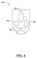
- FIG. 4illustrates a simplified schematic view of one embodiment of a remote control for a wireless light.
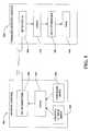
- FIG. 5illustrates a simplified schematic drawing of an RF communication system for controlling a light.
- FIG. 6illustrates a simplified schematic drawing of an alternative embodiment of a wireless lighting module.
- FIG. 7illustrates a block diagram of a system that provides illumination with a wireless light.
- FIG. 8illustrates a methodology that facilitates selectively emitting light in accordance with a wireless input.
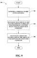
- FIG. 9illustrates a methodology that facilitates selectively emitting light based upon input from a sensor.
- ком ⁇ онентcan be a process running on a processor, a processor, an object, an executable, a program, and/or a computer.
- a componentcan be a process running on a processor, a processor, an object, an executable, a program, and/or a computer.
- an application running on a server and the servercan be a component.
- One or more componentscan reside within a process and a component can be localized on one computer and/or distributed between two or more computers.
- the claimed subject mattermay be implemented as a method, apparatus, or article of manufacture using standard programming and/or engineering techniques to produce software, firmware, hardware, or any combination thereof to control a computer to implement the disclosed subject matter.
- article of manufactureas used herein is intended to encompass a computer program accessible from any computer-readable device, carrier, or media.
- computer readable mediacan include but are not limited to magnetic storage devices (e.g., hard disk, floppy disk, magnetic strips, . . . ), optical disks (e.g., compact disk (CD), digital versatile disk (DVD), . . . ), smart cards, and flash memory devices (e.g., card, stick, key drive, . . . ).
- a carrier wavecan be employed to carry computer-readable electronic data such as those used in transmitting and receiving electronic mail or in accessing a network such as the Internet or a local area network (LAN).
- LANlocal area network
- the claimed subject matteris directed to wireless LED lighting.
- FIG. 1illustrated is a perspective view of one embodiment of a wireless lighting module 100 .
- the wireless lighting module 100includes a housing 110 and a plurality of LEDs 120 .
- the wireless lighting module 100includes 16 LEDs.
- the lighting modulemay include more LEDs 120 to provide greater illumination or fewer LEDs 120 to use less power.
- the wireless lighting module 100can include any number of LEDs 120 , and the LEDs 120 can be positioned at substantially any locations with respect to one another as well as in comparison to the housing 110 .
- the housing 110is constructed of plastic. Alternatively, the housing 110 can be constructed of metal or any other known material.
- the housing 110includes a mounting device for mounting the wireless lighting module 100 to a wall, ceiling, cabinet, or other surface. Exemplary mounting devices include screws, nails, adhesive, suction cups, magnets, VELCRO®, fixing posts, flanged heads of fasteners, and other known mounting devices.
- the housing 110is configured to be mounted under a cabinet or desk, on a mailbox, or on a wall or ceiling of a room, closet, attic, basement, garage, storage area, shed, wall unit, hallway, stairway, emergency exit path, or cabinet, or in any other indoor or outdoor location where light may be desired.
- one wireless lighting module(e.g., the wireless lighting module 100 ) illuminates an area of 20 square feet.
- the housing 110can be any size and/or shape and is not limited to the depicted illustration (e.g., the housing 110 can be dome shaped, pyramid shaped, cylindrical, . . . ). According to another example, the housing 110 can form a rope light.
- the LEDs 120 of the wireless lighting module 100are arranged in an array to disperse light over a desired area.
- one or more LEDs 120are arranged in a spotlight to focus light over a desired area.
- the LEDs 120are white.
- the LEDs 120are colored. In such an embodiment, all of the LEDs in the module 100 may be the same or different colors.
- the wireless lighting module 100further includes a light-transmitting cover 130 .
- the light-transmitting cover 130is transparent.
- the covermay be colored or frosted.
- the light-transmitting cover 130is smooth.
- the covermay be etched or otherwise textured.
- the cover 130may have any desired shape.
- the moduledoes not include a light-transmitting cover.
- the wireless lighting moduleincludes a filter (not shown).
- FIG. 2shows a simplified top plan view of the wireless lighting module 100 , with the housing 110 and cover 130 removed.
- the wireless lighting module 100includes a power source, such as a battery 210 .
- the power sourcemay be a solar cell.
- three “AAA” size alkaline batteriesare used as a power source.
- three “C” size alkaline batteriesare used. It should be understood that any number of known batteries may be used, including without limitation all known alkaline and nickel-cadmium batteries, depending on size and power requirements.
- the power sourcecan be any number and type of rechargeable batteries and/or non-rechargeable batteries.
- the power sourcecan be a combination of a solar cell and one or more batteries (e.g., rechargeable, non-rechargeable, . . . ).
- batteriese.g., rechargeable, non-rechargeable, . . .
- a batterycan supplement the power supplied by the solar cell (or vice versa) and/or the solar cell can recharge a battery.
- the battery 210is electrically connected to the LEDs 120 to provide power for the light output.
- the battery 210is also connected to a receiver 220 configured to receive a data stream.
- the receiver 220is configured to receive a data stream in the form of RF signals and is further configured to output data to logic 230 .
- the receiver 220is configured to receive data at up to 100 kbps and has a receive sensitivity of as little as ⁇ 115 dBm.
- the receiver 220is configured to receive IR signals.
- the receiver 220includes an integrated processor (not shown).
- the integrated processor of the receiver 220is separate from the logic 230 of the wireless lighting module 100 .
- the integrated processoris configured to convert an RF or IR data stream to digital data output.
- the integrated processormay be an integrated circuit, a microprocessor, or other known processor.
- the receiver 220may be a commercially available Maxim MAX1470 RF Integrated Circuit 300-450 MHz ASK Superheterodyne receiver.
- the battery 210is also connected to the logic 230 .
- the logic 230is configured to monitor data received by the receiver 220 . In one embodiment, described above, the receiver 220 outputs digital data. In an alternative embodiment, the receiver 220 outputs analog data and the logic 230 is configured to convert the analog data to digital data.
- the logic 230is configured to detect specific sequences of data, such as commands and channel data, as will be described in more detail below.
- the logic 230may be an integrated circuit, a microprocessor, or any known type of processor.
- the logic 230may be a commercially available Freescale Semiconductor MC68HC908QT microcontroller.
- the logic 230employs a power sequencing algorithm to conserve power. In this embodiment, the logic 230 stays in a “hibernation” mode to conserve power. The logic 230 is activated a few times per second to monitor the receiver 220 . If the logic 230 detects output from the receiver 220 , the logic 230 reads the data and executes commands according to a protocol described below. If the logic 230 does not detect output from the receiver 220 , it returns to hibernation mode.
- the logic 230is also in electric communication with the LEDs 120 .
- the logic 230maintains the on/off state of the LEDs 120 .
- the logic 230may be configured to control the brightness of the LEDs 120 .
- the logic 230is configured to turn off the LEDs 120 after a predetermined amount of time to conserve power.
- the logic 230is also configured to control pulse width modulation to extend battery life.
- the LEDs 120are color changing LEDs and the logic 230 is configured to control the color emitted by the LEDs 120 .
- the modulesmay be synchronized such that the logic of each module changes the light color at the same time or according to a user preference.
- FIG. 3illustrates a perspective view of one embodiment of a remote control 300 for a wireless lighting module (e.g., the wireless lighting module 100 of FIG. 1 ).
- the remote control 300includes a housing 310 .
- the housing 310is configured to be attached to a keychain.
- the housing 310is configured to be mounted to a wall.
- the remote control 300includes a button 320 configured to receive user input.
- the button 320receives an on/off toggle command.
- the remote control 300includes a plurality of buttons.
- the additional buttonsmay be configured to receive a separate “on” command and “off” command.
- the additional buttonsmay also be configured to receive a “dim” or “brightness” command or a color changing command.
- the remote control 300further includes a dip switch for receiving a channel number.
- the remote control 300employs dials, toggle switches, levers, knobs, buttons, or any other appropriate controls to receive user input.
- the remote control 300can utilize a touch panel for obtaining user input.
- the remote control 300further includes a transmitter 330 configured to transmit a signal.
- the transmitter 330is an RF transmitter.
- the transmitter 330is an IR transmitter.
- the transmitter 330includes an integrated processor (not shown), such as a Maxim MAX 1472 RF Integrated Circuit 300-450 MHz ASK transmitter and is configured to transmit data at up to 100 kbps.
- the remote control 300can include a transceiver that can receive data from a wireless lighting module as well as transmit data to the wireless lighting module.
- FIG. 4illustrates a simplified top plan view of a remote control 300 with a housing 310 removed.
- the remote control 300includes a power source, such as a battery 410 .
- the battery 410is a CR2032 coin cell battery. In alternative embodiments, any number of any known type of battery may be used.
- the batteryis electrically connected to and supplies power to the transmitter 330 .
- the battery 410is also connected to and supplies power to logic 420 .
- the logic 420is configured to monitor a switch (not shown) connected to the button 320 .
- the logic 420is further configured to build and send a control message to the transmitter 330 .
- the logic 420sends a digital control message to the transmitter 330 .
- An integrated circuit (not shown) of the transmitter 330then converts the digital control message to an analog control message for transmission as an RF signal.
- the transmitter 330is configured to transmit a digital RF signal.
- the logic 420sends an analog control message to the transmitter 330 .
- the logic 420is configured to recognize an on/off toggle command.
- the logic 420receives the on/off toggle command when a user presses the button 320 .
- the logic 420is configured to recognize a separate “on” command and “off” command.
- the logic 420is configured to recognize a “dim” or “brightness” command or a “color change” command.
- the logic 420outputs a control message containing the command and a channel number.
- the logic 420receives the channel number from a user input device.
- the logic 420looks up the channel number in a memory (not shown).
- the processorgenerates a random number to use as a channel number.
- FIG. 5is a schematic drawing of one embodiment of a remote control 500 in communication with a wireless lighting module 510 .
- the userselects a channel number on the remote control 500 through a channel number input 520 .
- Exemplary channel number inputs 520include dip switches, buttons, dials, knobs, a keypad, an LED touchscreen, or any other known input device.
- a usermay select more than one channel number to communicate with a plurality of wireless lighting modules.
- the channel numbermay be preprogrammed, randomly generated, or previously stored in a memory. The user then enters a command through a command input 530 .
- Exemplary command inputs 530include buttons, switches, dials, knobs, a keypad, an LED touchscreen, or any other known input device.
- the commandmay be an “on/off” toggle command, an “on” command, an “off” command, a “dim” command, a “brightness” command, a “color change” command, or a timer command.
- logic 540encodes the channel number and the command and instructs an RF transmitter 550 to transmit an RF signal that includes the encoded channel number and command.
- the RF transmitter 550transmits RF signals at a frequency of 433 MHz. In alternative embodiments, the RF transmitter may transmit at a user selected-frequency or at any predetermined frequency.
- the RF signalis transmitted once. In an alternative embodiment, the RF signal is transmitted a predetermined number of times, or for a predetermined time period. If more than one RF signal is transmitted, each transmission may be separated by a predetermined interval.
- the wireless lighting module 510includes an RF receiver 560 that monitors for RF signals at a predetermined frequency.
- the RF receiver 560periodically monitors for RF signals.
- the RF receiver 560continuously monitors for RF signals.
- the signalis transmitted to logic 570 , where the signal is decoded.
- the logic 570reads the decoded channel number and compares the decoded channel number to a module channel number.
- the module channel numbermay be selected by a user via a channel input device (not shown), or it may be pre-programmed.
- the logic 570processes the decoded command. For example, if the command is an on/off toggle command, the logic 570 will instruct an LED controller 580 to toggle a plurality of LEDs 590 . If the command is an “on” command, the logic 570 will determine if the plurality of LEDs 590 are in an “on” state. If the LEDs 590 are not in an “on” state, the logic 570 will instruct the LED controller 580 to activate the plurality of LEDs 590 .
- the RF transmitter 550 and the RF receiver 560are replaced with RF transceivers, thus allowing two-way communication.
- the remote controlis programmed to repeatedly transmit a command signal until a confirmation signal is received.
- the lighting moduleis programmed to transmit a confirmation signal upon receipt of an RF signal, or upon a decoded channel number matching a module channel number.
- RF transceiverscan enable providing the remote control 500 with feedback concerning a state associated with the wireless lighting module 510 (e.g., whether the LEDs 590 are in an “on” state, an “off” state, a color of the LEDs 590 , an intensity of the LEDs 590 , . . . ), battery life, and so forth.
- RF transceiverscan allow the wireless lighting module 510 to communicate with disparate wireless lighting module(s) (e.g., to repeat signals).
- FIG. 6is a schematic drawing of an alternative embodiment of a wireless lighting module 600 .
- the wireless lighting module 600is not controlled by a remote control, but is instead motion-controlled.
- the wireless lighting module 600includes a passive infrared sensor 610 configured to detect motion.
- the passive infrared sensor 610has a range of approximately 5 feet and a viewing angle of 110 degrees.
- the passive infrared sensor 610may have a range and viewing angle of any known passive infrared sensor.
- the passive infrared sensor 610is removably connected to the wireless lighting module 600 so that a user may connect any appropriate sensor.
- logic 620determines if the motion is above a predetermined threshold. If the motion is above the predetermined threshold, the logic 620 instructs an LED controller 630 to turn on at least one LED 640 . After the at least one LED 640 is turned on, the logic 620 starts a timer. The logic 620 will then instruct the LED controller 630 to turn off the at least one LED 640 if no motion is detected before the timer reaches a predetermined threshold.
- the wireless lighting module 600further includes at least one battery 650 .
- the battery 650supplies power to the logic 620 , the LED controller 630 , the at least one LED 640 , and any other additional electric components. Further, the battery 650 can supply power to the sensor 610 .
- the at least one battery 650includes 3 “AAA” alkaline batteries. In an alternative embodiment, the at least one battery 650 includes 3 “C” alkaline batteries. In other embodiment, the at least one battery 650 may be any number of known batteries, including without limitation all known alkaline and nickel-cadmium batteries. It is to be appreciated that any number and type of rechargeable and/or non-rechargeable batteries can be utilized in connection with the claimed subject matter.
- System 700includes a wireless lighting module 702 that can further comprise an interface component 704 , a battery 706 , an LED controller 708 , LEDs 710 , and/or logic 712 .
- the wireless lighting module 702can be incorporated into a housing (not shown). It is contemplated that any size and/or shape housing can be employed with the wireless lighting module 702 . According to another illustration, the housing can include at least a portion that is moveable (e.g., manually by a user, automatically with a motor or the like, . . . ) to allow for directing emitted light.
- a remote controlcan provide a signal to manipulate a moveable portion of the housing.
- the housingcan orient the LEDs 710 in substantially any manner to provide general lighting (e.g., illuminating an indoor or outdoor area), task lighting (e.g., reading), accent lighting, and so forth.
- the interface component 704can receive an input from a disparate device (e.g., the remote control 500 of FIG. 5 , the sensor 610 of FIG. 6 , . . . ).
- the interface component 704can provide various adaptors, connectors, channels, communication paths, etc. to enable interaction with the disparate device.
- the inputcan be wirelessly transmitted (e.g., via an RF signal, an IR signal, . . . ) from the disparate device to the interface component 704 ; thus, the interface component 704 can be a receiver and/or a transceiver that obtains the wirelessly transferred signal.
- an infrared sensor or motion sensorcan monitor occupancy in an environment and, upon detecting presence within the monitored environment, the sensor can transmit a wireless input to the interface component 704 .
- any type of sensorscan be utilized in connection with the claimed subject matter such as, but not limited to, infrared sensors, light sensors, proximity sensors, acoustic sensors, motion sensors, carbon monoxide and/or smoke detectors, thermal sensors, electromagnetic sensors, mechanical sensors, chemical sensors, and the like.
- any type of remote controlcan wirelessly communicate with the interface component 704 .
- the remote controlcan be a stand-alone remote control (e.g., the remote control 300 of FIG.
- the remote controlcan be a personal computer, a cellular phone, a smart phone, a laptop, a handheld communication device, a handheld computing device, a global positioning system, a personal digital assistant (PDA), and/or any other suitable device; such devices can communicate directly with the interface component 704 and/or via a network (e.g., local area network (LAN), wide area network (WAN), cellular network, . . . ).
- a networke.g., local area network (LAN), wide area network (WAN), cellular network, . . .
- RFIDradio frequency identification
- an RFID tag associated with a usercan be detected when in range of the interface component 704 , and lighting preferences of the particular user (e.g., retained in memory) can be effectuated in response to his or her detected presence.
- the interface component 704can be a sensor that can monitor a condition associated with the wireless lighting module 702 to generate the input.
- the interface component 704can be a connector, port, etc. that couples to such sensor.
- the interface component 704can wirelessly transmit data (e.g., feedback, related to a current and/or anticipated future state, . . . ) to a remote device and/or sensor.
- datae.g., feedback, related to a current and/or anticipated future state, . . .
- the interface component 704can wirelessly communicate with an interface component of a disparate wireless lighting module to enable coordinated operation between more than one wireless lighting module.
- an inputcan be retransmitted within a network of wireless lighting modules, where the network of lighting modules can be dispersed within a geographic area.
- the battery 706can be any number and/or type of battery.
- the battery 706can be a rechargeable battery.
- the battery 706can be a non-rechargeable battery.
- the battery 706supplies power to the wireless lighting module 702 to enable installing, moving, replacing, etc. the wireless lighting module 702 at substantially any indoor or outdoor location while mitigating the need for expensive and time consuming wiring and/or utilization of aesthetically unpleasing and potentially inconvenient cords commonly associated with conventional lighting.
- the LED controller 708can obtain instructions from the logic 712 to control operation of the LEDs 710 .
- the LED controller 708can receive and effectuate instructions to switch one or more LEDs 710 on and/or off, change an intensity of illumination (e.g., brightness), switch a wavelength of light emitted from the LEDs 710 (e.g., to change light color), manipulate direction of illumination (e.g., by moving, rotating, etc. one or more of the LEDs 710 ) and the like. Further, it is contemplated that any number, type, color, arrangement, etc. of LEDs 710 can be utilized with the wireless lighting module 702 .
- the logic 712employs the input obtained by the interface component 704 .
- the logic 712can further include a state modification component 714 , a timer component 716 , an intensity regulation component 718 , and/or a wavelength control component 720 ; however, it is to be appreciated that the logic 712 can include a subset of these components 714 - 720 .
- the state modification component 714utilizes the input obtained via the interface component 704 to generate an instruction to change a state of one of more of the LEDs 710 .
- the state modification component 714effectuates transitioning one or more LEDs 710 to an on state, an off state, etc.
- the state modification component 714can yield commands to strobe one or more LEDs 710 (e.g., periodically turning LED(s) 710 on and off with substantially any periodicity).
- the state modification component 714can decipher that a received input pertains to one or more of the LEDs 710 .
- the state modification component 714can analyze the input to determine whether to instruct the LED controller 708 to change the state (e.g., compare an input from a sensor to a threshold, evaluate whether a condition has been met, based upon retrieved instructions corresponding to the input retained in memory, . . . ).
- the timer component 716can operate in conjunction with the state modification component 714 .
- the timer component 716can enable delaying state changes.
- turning the LEDs 710 on or offcan be delayed for an amount of time by the timer component 716 .
- the amount of time for the delaycan be predetermined, randomly selected, included with the input obtained by the interface component 704 (e.g., based on a number of times a button of a remote control is depressed, . . . ), etc.
- the timer component 716can conserve battery life by enabling the state modification component 714 to switch the LEDs 710 to an off state at a particular time of day, after an elapsed amount of time subsequent to an input that turned the LEDs 710 to the on state, and so forth.
- the timer component 716can operate in conjunction with the intensity regulation component 718 and/or the wavelength control component 720 described below.
- the intensity regulation component 718can alter the intensity (e.g., brightness) of the LEDs 710 based upon the received input from the interface component 704 .
- the intensitycan be changed by the intensity regulation component 718 adjusting a proportion of LEDs 710 in an on state to LEDs 710 in an off state. Additionally or alternatively, the intensity regulation component 718 can control the intensity of light emitted by each of the LEDs 710 .
- the interface component 704can obtain RFID related input that identifies the presence of a particular user, and this user can have lighting preferences stored in memory (not shown) associated with the wireless lighting module 702 .
- the particular user's preferencesmay indicate that she desires the LEDs 710 to be dimly lit, which can be effectuated by the intensity regulation component 718 .
- the intensity regulation component 718can increase the brightness of the illumination of the LEDs 710 to a highest level (e.g., while the state modification component 714 can strobe the LEDs 710 , the wavelength control component 720 can change the color, . . . ). It is to be appreciated, however, that the claimed subject matter is not limited to the aforementioned examples.
- the wavelength control component 720can change the wavelength (e.g., color) of light generated by the LEDs 710 as a function of the input obtained by the interface component 704 .
- the LEDs 710can be color changing LEDs, and the wavelength control component 720 can yield commands to adjust the color based upon the input obtained by the interface component 704 .
- the LEDs 710can include subsets of LEDs that yield differing colors, and the wavelength control component 720 can select which of the LEDs 710 to turn to the on state to yield the desired color.
- FIGS. 8-9illustrate methodologies in accordance with the claimed subject matter.
- the methodologiesare depicted and described as a series of acts. It is to be understood and appreciated that the subject innovation is not limited by the acts illustrated and/or by the order of acts, for example acts can occur in various orders and/or concurrently, and with other acts not presented and described herein. Furthermore, not all illustrated acts may be required to implement the methodologies in accordance with the claimed subject matter. In addition, those skilled in the art will understand and appreciate that the methodologies could alternatively be represented as a series of interrelated states via a state diagram or events.
- an inputcan be wirelessly received to control illumination of an array of LEDs powered by a battery.
- the inputcan be obtained from any type of source (e.g., remote control, disparate wireless lighting module, differing device, sensor, . . . ).
- the inputcan be provided from the source via an RF signal, an IR signal, and so forth.
- the inputcan be analyzed to determine whether to alter the illumination of the array of LEDs.
- the illumination of the array of LEDscan be selectively adjusted based on the analyzed input. For example, LEDs can be transitioned to a differing state (e.g., turned on, turned off, . . . ), intensity of LEDs can be altered, color emitted can be changed, and so forth.
- a condition within an environmentcan be monitored.
- the conditioncan relate to motion, presence, pressure, temperature, location, sound, chemicals, light, or any condition that can be tracked with a sensor.
- a determinationcan be effectuated relating to whether to alter illumination of an array of LEDs powered by a battery based upon the monitored condition. For example, the determination can be made by comparing the monitored condition to a threshold. Moreover, a current state associated with the array of LEDs can be evaluated to determine whether a change in illumination should be effectuated.
- the illumination of the array of LEDscan be selectively altered based on the monitored condition.
- LEDscan be transitioned to an on state when motion is detected.
- the LEDscan be turned off when no motion is detected (e.g., for more than a predetermined amount of time).
- the terms (including a reference to a “means”) used to describe such componentsare intended to correspond, unless otherwise indicated, to any component which performs the specified function of the described component (e.g., a functional equivalent), even though not structurally equivalent to the disclosed structure, which performs the function in the herein illustrated exemplary aspects of the claimed subject matter.
- the innovationincludes a system as well as a computer-readable medium having computer-executable instructions for performing the acts and/or events of the various methods of the claimed subject matter.
Landscapes
- Engineering & Computer Science (AREA)
- General Engineering & Computer Science (AREA)
- Physics & Mathematics (AREA)
- Electromagnetism (AREA)
- General Physics & Mathematics (AREA)
- Computer Networks & Wireless Communication (AREA)
- Circuit Arrangement For Electric Light Sources In General (AREA)
Abstract
Description
Claims (11)
Priority Applications (47)
| Application Number | Priority Date | Filing Date | Title |
|---|---|---|---|
| US11/692,075US8203445B2 (en) | 2006-03-28 | 2007-03-27 | Wireless lighting |
| US12/626,640US8033686B2 (en) | 2006-03-28 | 2009-11-26 | Wireless lighting devices and applications |
| US12/772,563US8362713B2 (en) | 2006-03-28 | 2010-05-03 | Wireless lighting devices and grid-shifting applications |
| US12/827,574US8491159B2 (en) | 2006-03-28 | 2010-06-30 | Wireless emergency lighting system |
| US12/903,273US8519566B2 (en) | 2006-03-28 | 2010-10-13 | Remote switch sensing in lighting devices |
| US12/942,134US8829799B2 (en) | 2006-03-28 | 2010-11-09 | Autonomous grid shifting lighting device |
| US13/247,620US9247623B2 (en) | 2006-03-28 | 2011-09-28 | Switch sensing emergency lighting power supply |
| US13/267,851US9074736B2 (en) | 2006-03-28 | 2011-10-06 | Power outage detector and transmitter |
| US13/283,468US9338839B2 (en) | 2006-03-28 | 2011-10-27 | Off-grid LED power failure lights |
| US13/309,196US9078313B2 (en) | 2006-03-28 | 2011-12-01 | Lighting wall switch with power failure capability |
| US13/315,414US8994276B2 (en) | 2006-03-28 | 2011-12-09 | Grid shifting system for a lighting circuit |
| US13/335,014US9066393B2 (en) | 2006-03-28 | 2011-12-22 | Wireless power inverter for lighting |
| US13/335,147US20120098439A1 (en) | 2007-03-27 | 2011-12-22 | Coordinated System of Battery Powered Wireless Lights |
| US13/469,705US9342967B2 (en) | 2006-03-28 | 2012-05-11 | Motion activated off grid LED light |
| US13/723,803US9252595B2 (en) | 2006-03-28 | 2012-12-21 | Distributed energy management using grid-shifting devices |
| US13/789,570US9247625B2 (en) | 2006-03-28 | 2013-03-07 | Detection and wireless control for auxiliary emergency lighting |
| US13/928,106US8764242B2 (en) | 2006-03-28 | 2013-06-26 | Integrated power outage lighting system controller |
| US13/949,856US9236767B2 (en) | 2006-03-28 | 2013-07-24 | Remote switch sensing in lighting devices |
| US14/284,122US10154555B2 (en) | 2006-03-28 | 2014-05-21 | Wireless lighting network with external remote control |
| US14/468,821US9089016B2 (en) | 2006-03-28 | 2014-08-26 | Battery backup motion sensing lighting device |
| US14/627,214US9351353B2 (en) | 2006-03-28 | 2015-02-20 | Coordinated autonomous network of grid powered lighting devices |
| US14/740,833US9392669B2 (en) | 2006-03-28 | 2015-06-16 | Line protection and coupling circuit for switch sensing devices |
| US14/974,573US9543788B2 (en) | 2006-03-28 | 2015-12-18 | Standby switch sense emergency lighting device |
| US14/974,521US10004128B2 (en) | 2006-03-28 | 2015-12-18 | Grid connected coordinated lighting adapter |
| US15/145,415US10117315B2 (en) | 2006-03-28 | 2016-05-03 | Network of motion sensor lights with synchronized operation |
| US15/147,422US9807858B2 (en) | 2006-03-28 | 2016-05-05 | Coordinated network of autonomous off grid powered lighting devices |
| US15/215,001US9655217B2 (en) | 2006-03-28 | 2016-07-20 | Cloud connected motion sensor lighting grid |
| US15/375,657US10601244B2 (en) | 2006-03-28 | 2016-12-12 | Emergency lighting device with remote lighting |
| US15/486,129US9860965B2 (en) | 2006-03-28 | 2017-04-12 | Cloud connected lighting system |
| US15/726,196US10009987B2 (en) | 2006-03-28 | 2017-10-05 | Wireless lighting system with camera operation |
| US15/827,611US10034359B2 (en) | 2006-03-28 | 2017-11-30 | Cloud-connected off-grid lighting and video system |
| US15/876,040US10098211B2 (en) | 2006-03-28 | 2018-01-19 | Wirelessly controllable lighting module |
| US15/884,096US20180177032A1 (en) | 2006-03-28 | 2018-01-30 | Wirelessly controllable communication module |
| US15/905,550US10448489B2 (en) | 2006-03-28 | 2018-02-26 | Motion sensitive communication device for controlling IR lighting |
| US15/905,475US10085332B2 (en) | 2006-03-28 | 2018-02-26 | Motion sensitive communication device for controlling lighting |
| US15/905,581US10342104B2 (en) | 2006-03-28 | 2018-02-26 | Video on demand for communication devices |
| US15/965,723US11129246B2 (en) | 2006-03-28 | 2018-04-27 | Grid connected coordinated lighting adapter |
| US15/983,515US10390413B2 (en) | 2006-03-28 | 2018-05-18 | Wirelessly controllable communication module |
| US16/022,529US10499478B2 (en) | 2006-03-28 | 2018-06-28 | Cloud-connected off-grid lighting and video system |
| US16/159,329US11039513B1 (en) | 2006-03-28 | 2018-10-12 | Wireless emergency lighting system |
| US16/226,305US10448491B1 (en) | 2006-03-28 | 2018-12-19 | Motion sensitive communication device for controlling IR lighting |
| US16/376,246US11523488B1 (en) | 2006-03-28 | 2019-04-05 | Wirelessly controllable communication module |
| US16/392,069US10912178B1 (en) | 2006-03-28 | 2019-04-23 | System for providing video on demand |
| US16/507,695US10999914B1 (en) | 2006-03-28 | 2019-07-10 | Motion sensitive lighting devices |
| US16/556,686US10966306B1 (en) | 2006-03-28 | 2019-08-30 | Bridge device for connecting electronic devices |
| US16/781,668US11109471B1 (en) | 2006-03-28 | 2020-02-04 | Bridge device for connecting electronic devices |
| US16/811,978US11101686B1 (en) | 2006-03-28 | 2020-03-06 | Emergency lighting device with remote lighting |
Applications Claiming Priority (2)
| Application Number | Priority Date | Filing Date | Title |
|---|---|---|---|
| US78663606P | 2006-03-28 | 2006-03-28 | |
| US11/692,075US8203445B2 (en) | 2006-03-28 | 2007-03-27 | Wireless lighting |
Related Parent Applications (2)
| Application Number | Title | Priority Date | Filing Date |
|---|---|---|---|
| US11/692,075Continuation-In-PartUS8203445B2 (en) | 2006-03-28 | 2007-03-27 | Wireless lighting |
| US11/847,509Continuation-In-PartUS8669716B2 (en) | 2006-03-28 | 2007-08-30 | Wireless light bulb |
Related Child Applications (4)
| Application Number | Title | Priority Date | Filing Date |
|---|---|---|---|
| US11/692,075Continuation-In-PartUS8203445B2 (en) | 2006-03-28 | 2007-03-27 | Wireless lighting |
| US11/847,509Continuation-In-PartUS8669716B2 (en) | 2006-03-28 | 2007-08-30 | Wireless light bulb |
| US12/903,273Continuation-In-PartUS8519566B2 (en) | 2006-03-28 | 2010-10-13 | Remote switch sensing in lighting devices |
| US13/469,705ContinuationUS9342967B2 (en) | 2006-03-28 | 2012-05-11 | Motion activated off grid LED light |
Publications (2)
| Publication Number | Publication Date |
|---|---|
| US20070229250A1 US20070229250A1 (en) | 2007-10-04 |
| US8203445B2true US8203445B2 (en) | 2012-06-19 |
Family
ID=38558004
Family Applications (3)
| Application Number | Title | Priority Date | Filing Date |
|---|---|---|---|
| US11/692,075Active2029-09-09US8203445B2 (en) | 2006-03-28 | 2007-03-27 | Wireless lighting |
| US13/469,705ActiveUS9342967B2 (en) | 2006-03-28 | 2012-05-11 | Motion activated off grid LED light |
| US15/145,415Expired - Fee RelatedUS10117315B2 (en) | 2006-03-28 | 2016-05-03 | Network of motion sensor lights with synchronized operation |
Family Applications After (2)
| Application Number | Title | Priority Date | Filing Date |
|---|---|---|---|
| US13/469,705ActiveUS9342967B2 (en) | 2006-03-28 | 2012-05-11 | Motion activated off grid LED light |
| US15/145,415Expired - Fee RelatedUS10117315B2 (en) | 2006-03-28 | 2016-05-03 | Network of motion sensor lights with synchronized operation |
Country Status (1)
| Country | Link |
|---|---|
| US (3) | US8203445B2 (en) |
Cited By (68)
| Publication number | Priority date | Publication date | Assignee | Title |
|---|---|---|---|---|
| US20100093274A1 (en)* | 2008-10-15 | 2010-04-15 | Jian Xu | Fault-tolerant non-random signal repeating system for building electric control |
| US20100097186A1 (en)* | 2008-10-17 | 2010-04-22 | Rockwell Automation Technologies, Inc. | User interface devices for control of machine systems |
| US20100134283A1 (en)* | 2007-03-30 | 2010-06-03 | Chadwell Thomas J | Method and apparatus for delivering visual information |
| US20100295457A1 (en)* | 2009-05-20 | 2010-11-25 | Pixart Imaging Inc. | Light control system and control method thereof |
| US20110260619A1 (en)* | 2010-03-29 | 2011-10-27 | Innosys, Inc. | LED Dimming Driver |
| US20120181934A1 (en)* | 2009-08-05 | 2012-07-19 | Koninklijke Philips Electronics N.V. | Light guiding system and a method for controlling the same |
| US20130033178A1 (en)* | 2011-08-02 | 2013-02-07 | Jung-Tang Huang | Network connection device based on light source |
| US8502454B2 (en) | 2008-02-08 | 2013-08-06 | Innosys, Inc | Solid state semiconductor LED replacement for fluorescent lamps |
| US8502477B2 (en) | 2009-04-11 | 2013-08-06 | Innosys, Inc | Dimmable power supply |
| US20130221874A1 (en)* | 2009-03-20 | 2013-08-29 | Glo-Blades International Inc. | Glo-blades skates |
| US20130338798A1 (en)* | 2009-05-28 | 2013-12-19 | Rockwell Automation Technologies, Inc. | Wireless user interface system performance monitoring |
| US8624500B2 (en) | 2009-08-07 | 2014-01-07 | Led Roadway Lighting Ltd | Single-ended primary inductance converter (SEPIC) based power supply for driving multiple strings of light emitting diodes (LEDs) in roadway lighting fixtures |
| US8707601B1 (en) | 2013-03-14 | 2014-04-29 | John Kirk | Indicator light for filming |
| US20140152439A1 (en)* | 2012-12-03 | 2014-06-05 | James H. Nguyen | Security System |
| US8760072B2 (en) | 2009-01-27 | 2014-06-24 | Led Roadway Lighting Ltd. | Power supply for light emitting diode roadway lighting fixture |
| US8773031B2 (en) | 2010-11-22 | 2014-07-08 | Innosys, Inc. | Dimmable timer-based LED power supply |
| US8807785B2 (en) | 2008-05-23 | 2014-08-19 | Ilumisys, Inc. | Electric shock resistant L.E.D. based light |
| US8840282B2 (en) | 2010-03-26 | 2014-09-23 | Ilumisys, Inc. | LED bulb with internal heat dissipating structures |
| US8884531B1 (en) | 2013-08-08 | 2014-11-11 | Test Rite International Co., Ltd. | Intelligent solar lighting system |
| US8894430B2 (en) | 2010-10-29 | 2014-11-25 | Ilumisys, Inc. | Mechanisms for reducing risk of shock during installation of light tube |
| US8901827B1 (en) | 2013-08-08 | 2014-12-02 | Test Rite International Co., Ltd. | Intelligent solar lighting system |
| US8901823B2 (en) | 2008-10-24 | 2014-12-02 | Ilumisys, Inc. | Light and light sensor |
| US8928025B2 (en) | 2007-12-20 | 2015-01-06 | Ilumisys, Inc. | LED lighting apparatus with swivel connection |
| US8946996B2 (en) | 2008-10-24 | 2015-02-03 | Ilumisys, Inc. | Light and light sensor |
| US20150069915A1 (en)* | 2013-09-10 | 2015-03-12 | Panasonic Intellectual Property Corporation Of America | Method for controlling communications terminal and program |
| US8987997B2 (en) | 2012-02-17 | 2015-03-24 | Innosys, Inc. | Dimming driver with stealer switch |
| US9013119B2 (en) | 2010-03-26 | 2015-04-21 | Ilumisys, Inc. | LED light with thermoelectric generator |
| US9101026B2 (en) | 2008-10-24 | 2015-08-04 | Ilumisys, Inc. | Integration of LED lighting with building controls |
| US9163794B2 (en) | 2012-07-06 | 2015-10-20 | Ilumisys, Inc. | Power supply assembly for LED-based light tube |
| US9184518B2 (en) | 2012-03-02 | 2015-11-10 | Ilumisys, Inc. | Electrical connector header for an LED-based light |
| US9267650B2 (en) | 2013-10-09 | 2016-02-23 | Ilumisys, Inc. | Lens for an LED-based light |
| US9271367B2 (en) | 2012-07-09 | 2016-02-23 | Ilumisys, Inc. | System and method for controlling operation of an LED-based light |
| US9278645B1 (en) | 2015-01-16 | 2016-03-08 | Meyer Products, Llc | Method and apparatus for installing and operating an auxiliary lighting system using a trailer plug |
| US9285084B2 (en) | 2013-03-14 | 2016-03-15 | Ilumisys, Inc. | Diffusers for LED-based lights |
| WO2016073484A1 (en)* | 2014-11-03 | 2016-05-12 | Integrated Systems International, Llc | Method and apparatus for producing various colors and reducing or eliminating other visible colors |
| US9346394B1 (en) | 2015-01-16 | 2016-05-24 | Meyer Products, Llc | Method and apparatus for installing and operating an auxiliary lighting system using a vehicle light plug |
| US9353939B2 (en) | 2008-10-24 | 2016-05-31 | iLumisys, Inc | Lighting including integral communication apparatus |
| US9510400B2 (en) | 2014-05-13 | 2016-11-29 | Ilumisys, Inc. | User input systems for an LED-based light |
| US20170043708A1 (en)* | 2015-08-14 | 2017-02-16 | Curtis Watson | Vehicle tracking system |
| US9574717B2 (en) | 2014-01-22 | 2017-02-21 | Ilumisys, Inc. | LED-based light with addressed LEDs |
| US9751452B2 (en) | 2015-01-16 | 2017-09-05 | Meyer Products, Llc | Method and apparatus for installing and operating an auxiliary lighting system using a vehicle light plug |
| US9981597B2 (en) | 2015-01-16 | 2018-05-29 | Meyer Products Llc | Method and apparatus for installing and operating an auxiliary lighting system using a vehicle electric plug |
| CN108886860A (en)* | 2016-03-04 | 2018-11-23 | 飞利浦照明控股有限公司 | Control system for controlling lighting equipment arranged to provide functional and/or mood lighting |
| US10155468B1 (en) | 2017-09-01 | 2018-12-18 | Meyer Products, Llc | Method and apparatus for controlling auxiliary lighting using a vehicle electric plug |
| US10161568B2 (en) | 2015-06-01 | 2018-12-25 | Ilumisys, Inc. | LED-based light with canted outer walls |
| US10176689B2 (en) | 2008-10-24 | 2019-01-08 | Ilumisys, Inc. | Integration of led lighting control with emergency notification systems |
| US10270286B2 (en) | 2015-10-27 | 2019-04-23 | Zhejiang Shenghui Lighting Co., Ltd | LED smart control circuit and LED lighting device containing the same |
| US10292427B2 (en) | 2016-04-25 | 2019-05-21 | Lunatech, Llc | Electronic vaporizing device having lighting control functionality |
| US10308170B2 (en) | 2015-01-16 | 2019-06-04 | Meyer Products, Llc | Method and apparatus for controlling auxiliary lighting using a vehicle electric plug |
| US10333341B2 (en) | 2016-03-08 | 2019-06-25 | Ledvance Llc | LED lighting system with battery for demand management and emergency lighting |
| USRE48090E1 (en)* | 2007-04-20 | 2020-07-07 | Ideal Industries Lighting Llc | Illumination control network |
| US10891881B2 (en) | 2012-07-30 | 2021-01-12 | Ultravision Technologies, Llc | Lighting assembly with LEDs and optical elements |
| US20210267038A1 (en)* | 2011-06-10 | 2021-08-26 | Lutron Technology Company Llc | Method and Apparatus for Adjusting an Ambient Light Threshold |
| US11317497B2 (en) | 2019-06-20 | 2022-04-26 | Express Imaging Systems, Llc | Photocontroller and/or lamp with photocontrols to control operation of lamp |
| US11335175B2 (en) | 2011-08-31 | 2022-05-17 | Vaxcel International Co., Ltd. | Two-level LED security light with motion sensor |
| US20220246026A1 (en)* | 2019-07-11 | 2022-08-04 | Unilux Inc. | Power-saving control system using remote-control communication |
| US11632848B2 (en) | 2019-06-03 | 2023-04-18 | Pauly Enterprises, LLC | Interconnected remote control lighting system |
| US11636870B2 (en) | 2020-08-20 | 2023-04-25 | Denso International America, Inc. | Smoking cessation systems and methods |
| US11760170B2 (en) | 2020-08-20 | 2023-09-19 | Denso International America, Inc. | Olfaction sensor preservation systems and methods |
| US11760169B2 (en) | 2020-08-20 | 2023-09-19 | Denso International America, Inc. | Particulate control systems and methods for olfaction sensors |
| US11813926B2 (en) | 2020-08-20 | 2023-11-14 | Denso International America, Inc. | Binding agent and olfaction sensor |
| US11828210B2 (en) | 2020-08-20 | 2023-11-28 | Denso International America, Inc. | Diagnostic systems and methods of vehicles using olfaction |
| US11881093B2 (en) | 2020-08-20 | 2024-01-23 | Denso International America, Inc. | Systems and methods for identifying smoking in vehicles |
| US11932080B2 (en) | 2020-08-20 | 2024-03-19 | Denso International America, Inc. | Diagnostic and recirculation control systems and methods |
| US12017506B2 (en) | 2020-08-20 | 2024-06-25 | Denso International America, Inc. | Passenger cabin air control systems and methods |
| US12251991B2 (en) | 2020-08-20 | 2025-03-18 | Denso International America, Inc. | Humidity control for olfaction sensors |
| US12269315B2 (en) | 2020-08-20 | 2025-04-08 | Denso International America, Inc. | Systems and methods for measuring and managing odor brought into rental vehicles |
| US12377711B2 (en) | 2020-08-20 | 2025-08-05 | Denso International America, Inc. | Vehicle feature control systems and methods based on smoking |
Families Citing this family (195)
| Publication number | Priority date | Publication date | Assignee | Title |
|---|---|---|---|---|
| CA2616030A1 (en) | 2005-07-20 | 2007-01-25 | Lab Partners Associates, Inc. | Wireless photographic communication system and method |
| CN101496387B (en) | 2006-03-06 | 2012-09-05 | 思科技术公司 | System and method for access authentication in a mobile wireless network |
| US8519566B2 (en) | 2006-03-28 | 2013-08-27 | Wireless Environment, Llc | Remote switch sensing in lighting devices |
| US8491159B2 (en)* | 2006-03-28 | 2013-07-23 | Wireless Environment, Llc | Wireless emergency lighting system |
| US8669716B2 (en) | 2007-08-30 | 2014-03-11 | Wireless Environment, Llc | Wireless light bulb |
| US8362713B2 (en)* | 2006-03-28 | 2013-01-29 | Wireless Environment, Llc | Wireless lighting devices and grid-shifting applications |
| US9860965B2 (en) | 2006-03-28 | 2018-01-02 | Wireless Environment, Llc | Cloud connected lighting system |
| US8994276B2 (en) | 2006-03-28 | 2015-03-31 | Wireless Environment, Llc | Grid shifting system for a lighting circuit |
| US11523488B1 (en) | 2006-03-28 | 2022-12-06 | Amazon Technologies, Inc. | Wirelessly controllable communication module |
| EP1890519A1 (en)* | 2006-08-18 | 2008-02-20 | BRITISH TELECOMMUNICATIONS public limited company | Environmental monitor |
| KR100791117B1 (en)* | 2006-11-09 | 2008-01-02 | 주식회사 서비전자 | RF communication device control device and method |
| US20080183307A1 (en)* | 2007-01-26 | 2008-07-31 | Autani Corporation | Upgradeable Automation Devices, Systems, Architectures, and Methods |
| EP2162792A4 (en) | 2007-05-29 | 2011-08-24 | Lab Partners Associates Inc | System and method for maintaining hot shoe communications between a camera and a wireless device |
| US8057069B2 (en)* | 2007-07-03 | 2011-11-15 | Optimus Services Ag | Graphical user interface manipulable lighting |
| DE102007049480A1 (en)* | 2007-10-11 | 2009-04-23 | Avertronics Inc. | Lamp device for illuminating e.g. stage, has circuit deciding, corresponding to adjustment of module switch, whether data packet signal is processed, where circuit decodes data packet signal and controls illuminant if signal is processed |
| US8355041B2 (en) | 2008-02-14 | 2013-01-15 | Cisco Technology, Inc. | Telepresence system for 360 degree video conferencing |
| US8797377B2 (en) | 2008-02-14 | 2014-08-05 | Cisco Technology, Inc. | Method and system for videoconference configuration |
| TWI450632B (en)* | 2008-02-18 | 2014-08-21 | Interactive LED display system for entertainment | |
| US20090224690A1 (en)* | 2008-03-05 | 2009-09-10 | Jian Xu | Economy mode for lighting control system |
| TWM350941U (en)* | 2008-03-12 | 2009-02-11 | Forechen Inc | Light source regulating switch device |
| US8319819B2 (en) | 2008-03-26 | 2012-11-27 | Cisco Technology, Inc. | Virtual round-table videoconference |
| US8531134B2 (en) | 2008-04-14 | 2013-09-10 | Digital Lumens Incorporated | LED-based lighting methods, apparatus, and systems employing LED light bars, occupancy sensing, local state machine, and time-based tracking of operational modes |
| US8610376B2 (en) | 2008-04-14 | 2013-12-17 | Digital Lumens Incorporated | LED lighting methods, apparatus, and systems including historic sensor data logging |
| US8610377B2 (en) | 2008-04-14 | 2013-12-17 | Digital Lumens, Incorporated | Methods, apparatus, and systems for prediction of lighting module performance |
| US8368321B2 (en) | 2008-04-14 | 2013-02-05 | Digital Lumens Incorporated | Power management unit with rules-based power consumption management |
| US8552664B2 (en) | 2008-04-14 | 2013-10-08 | Digital Lumens Incorporated | Power management unit with ballast interface |
| US8823277B2 (en) | 2008-04-14 | 2014-09-02 | Digital Lumens Incorporated | Methods, systems, and apparatus for mapping a network of lighting fixtures with light module identification |
| US8866408B2 (en) | 2008-04-14 | 2014-10-21 | Digital Lumens Incorporated | Methods, apparatus, and systems for automatic power adjustment based on energy demand information |
| US8841859B2 (en) | 2008-04-14 | 2014-09-23 | Digital Lumens Incorporated | LED lighting methods, apparatus, and systems including rules-based sensor data logging |
| US10539311B2 (en) | 2008-04-14 | 2020-01-21 | Digital Lumens Incorporated | Sensor-based lighting methods, apparatus, and systems |
| US20120235579A1 (en) | 2008-04-14 | 2012-09-20 | Digital Lumens, Incorporated | Methods, apparatus and systems for providing occupancy-based variable lighting |
| US8373362B2 (en) | 2008-04-14 | 2013-02-12 | Digital Lumens Incorporated | Methods, systems, and apparatus for commissioning an LED lighting fixture with remote reporting |
| US8339069B2 (en) | 2008-04-14 | 2012-12-25 | Digital Lumens Incorporated | Power management unit with power metering |
| US8754589B2 (en) | 2008-04-14 | 2014-06-17 | Digtial Lumens Incorporated | Power management unit with temperature protection |
| US8805550B2 (en)* | 2008-04-14 | 2014-08-12 | Digital Lumens Incorporated | Power management unit with power source arbitration |
| US8543249B2 (en) | 2008-04-14 | 2013-09-24 | Digital Lumens Incorporated | Power management unit with modular sensor bus |
| US8390667B2 (en) | 2008-04-15 | 2013-03-05 | Cisco Technology, Inc. | Pop-up PIP for people not in picture |
| US8364325B2 (en) | 2008-06-02 | 2013-01-29 | Adura Technologies, Inc. | Intelligence in distributed lighting control devices |
| US8275471B2 (en) | 2009-11-06 | 2012-09-25 | Adura Technologies, Inc. | Sensor interface for wireless control |
| US20100026195A1 (en)* | 2008-07-29 | 2010-02-04 | Potter Noel R | Multi-Modal Light |
| GB2462146A (en)* | 2008-07-31 | 2010-02-03 | Humankind Ltd | Mains power failure emergency lighting |
| US8009042B2 (en) | 2008-09-03 | 2011-08-30 | Lutron Electronics Co., Inc. | Radio-frequency lighting control system with occupancy sensing |
| US8694658B2 (en) | 2008-09-19 | 2014-04-08 | Cisco Technology, Inc. | System and method for enabling communication sessions in a network environment |
| US20100079274A1 (en)* | 2008-09-28 | 2010-04-01 | Wilson Robert H | System for Wireless Activation of Communication Indicators within an Industrial or Professional Working Environment |
| US8018338B2 (en)* | 2008-10-19 | 2011-09-13 | Everspring Industry Co. Ltd. | Motion sensor system with motor-actuated detection unit |
| US8497634B2 (en)* | 2008-10-23 | 2013-07-30 | Innovation Works, Inc. | Wireless lighting system for staircases and passageways |
| TWI397343B (en)* | 2008-11-21 | 2013-05-21 | Ind Tech Res Inst | Solar-powered wireless communication module with sunshine intensity measurement ability |
| CA2957199C (en) | 2008-11-26 | 2019-01-08 | Wireless Environment, Llc | Wireless lighting devices and applications |
| KR100982331B1 (en)* | 2008-12-01 | 2010-09-15 | 삼성에스디아이 주식회사 | Plasma display device |
| US8718461B2 (en) | 2009-02-12 | 2014-05-06 | Lab Partners Associates, Inc. | Photographic synchronization optimization system and method |
| WO2010093927A2 (en)* | 2009-02-12 | 2010-08-19 | Lab Partners Associates, Inc. | Systems and methods for controlling a photographic modeling light using one or more camera body control signals |
| US8659637B2 (en) | 2009-03-09 | 2014-02-25 | Cisco Technology, Inc. | System and method for providing three dimensional video conferencing in a network environment |
| US20100259200A1 (en)* | 2009-04-14 | 2010-10-14 | Beausoleil David M | Led lighting device |
| US8536802B2 (en) | 2009-04-14 | 2013-09-17 | Digital Lumens Incorporated | LED-based lighting methods, apparatus, and systems employing LED light bars, occupancy sensing, and local state machine |
| US8954170B2 (en) | 2009-04-14 | 2015-02-10 | Digital Lumens Incorporated | Power management unit with multi-input arbitration |
| US8593135B2 (en) | 2009-04-14 | 2013-11-26 | Digital Lumens Incorporated | Low-cost power measurement circuit |
| US8659639B2 (en) | 2009-05-29 | 2014-02-25 | Cisco Technology, Inc. | System and method for extending communications between participants in a conferencing environment |
| US8165724B2 (en)* | 2009-06-17 | 2012-04-24 | Sharp Laboratories Of America, Inc. | Methods and systems for power-controlling display devices |
| US8902149B2 (en)* | 2009-06-17 | 2014-12-02 | Sharp Laboratories Of America, Inc. | Methods and systems for power control event responsive display devices |
| US8573807B2 (en)* | 2009-06-26 | 2013-11-05 | Intel Corporation | Light devices having controllable light emitting elements |
| WO2011005991A2 (en)* | 2009-07-08 | 2011-01-13 | AEQUITAS Innovation | Systems and methods for prevention of theft of led light bulbs |
| US9082297B2 (en)* | 2009-08-11 | 2015-07-14 | Cisco Technology, Inc. | System and method for verifying parameters in an audiovisual environment |
| EP2474205A1 (en)* | 2009-09-04 | 2012-07-11 | American DJ Supply, Inc. | Wireless controller for lighting system |
| US8716953B2 (en) | 2009-12-07 | 2014-05-06 | At&T Intellectual Property I, L.P. | Mechanisms for light management |
| US8457839B2 (en)* | 2010-01-07 | 2013-06-04 | Ford Global Technologies, Llc | Multi-display vehicle information system and method |
| US20110181408A1 (en)* | 2010-01-28 | 2011-07-28 | Paul Gailey Greenis | Public Tactical Message System |
| US10977965B2 (en) | 2010-01-29 | 2021-04-13 | Avery Dennison Retail Information Services, Llc | Smart sign box using electronic interactions |
| EP3133579B1 (en) | 2010-01-29 | 2020-03-04 | Avery Dennison Corporation | Smart sign box using electronic interactions |
| US9225916B2 (en) | 2010-03-18 | 2015-12-29 | Cisco Technology, Inc. | System and method for enhancing video images in a conferencing environment |
| TWI435651B (en)* | 2010-04-22 | 2014-04-21 | Dartpoint Tech Co Ltd | Wireless light control system with light control device and method thereof |
| US20130211844A1 (en)* | 2010-05-06 | 2013-08-15 | Laurence P. Sadwick | Solar Powered Portable Control Panel |
| US9313452B2 (en) | 2010-05-17 | 2016-04-12 | Cisco Technology, Inc. | System and method for providing retracting optics in a video conferencing environment |
| CN102300358B (en)* | 2010-06-22 | 2014-04-30 | 太琦科技股份有限公司 | Wireless lighting control system with lighting control device and method thereof |
| US8896655B2 (en) | 2010-08-31 | 2014-11-25 | Cisco Technology, Inc. | System and method for providing depth adaptive video conferencing |
| US8599934B2 (en) | 2010-09-08 | 2013-12-03 | Cisco Technology, Inc. | System and method for skip coding during video conferencing in a network environment |
| US8599865B2 (en) | 2010-10-26 | 2013-12-03 | Cisco Technology, Inc. | System and method for provisioning flows in a mobile network environment |
| US8699457B2 (en) | 2010-11-03 | 2014-04-15 | Cisco Technology, Inc. | System and method for managing flows in a mobile network environment |
| EP3517839B1 (en) | 2010-11-04 | 2021-09-22 | Digital Lumens Incorporated | Method, apparatus, and system for occupancy sensing |
| US8902244B2 (en) | 2010-11-15 | 2014-12-02 | Cisco Technology, Inc. | System and method for providing enhanced graphics in a video environment |
| US9143725B2 (en) | 2010-11-15 | 2015-09-22 | Cisco Technology, Inc. | System and method for providing enhanced graphics in a video environment |
| US9338394B2 (en) | 2010-11-15 | 2016-05-10 | Cisco Technology, Inc. | System and method for providing enhanced audio in a video environment |
| US8730297B2 (en) | 2010-11-15 | 2014-05-20 | Cisco Technology, Inc. | System and method for providing camera functions in a video environment |
| US8542264B2 (en) | 2010-11-18 | 2013-09-24 | Cisco Technology, Inc. | System and method for managing optics in a video environment |
| US8723914B2 (en) | 2010-11-19 | 2014-05-13 | Cisco Technology, Inc. | System and method for providing enhanced video processing in a network environment |
| US9124358B2 (en)* | 2010-11-29 | 2015-09-01 | Kourosh Pahlavan | Passive wireless connection |
| US9111138B2 (en) | 2010-11-30 | 2015-08-18 | Cisco Technology, Inc. | System and method for gesture interface control |
| USD678308S1 (en) | 2010-12-16 | 2013-03-19 | Cisco Technology, Inc. | Display screen with graphical user interface |
| USD678320S1 (en) | 2010-12-16 | 2013-03-19 | Cisco Technology, Inc. | Display screen with graphical user interface |
| USD678894S1 (en) | 2010-12-16 | 2013-03-26 | Cisco Technology, Inc. | Display screen with graphical user interface |
| USD682864S1 (en) | 2010-12-16 | 2013-05-21 | Cisco Technology, Inc. | Display screen with graphical user interface |
| USD682854S1 (en) | 2010-12-16 | 2013-05-21 | Cisco Technology, Inc. | Display screen for graphical user interface |
| USD678307S1 (en) | 2010-12-16 | 2013-03-19 | Cisco Technology, Inc. | Display screen with graphical user interface |
| USD682294S1 (en) | 2010-12-16 | 2013-05-14 | Cisco Technology, Inc. | Display screen with graphical user interface |
| USD682293S1 (en) | 2010-12-16 | 2013-05-14 | Cisco Technology, Inc. | Display screen with graphical user interface |
| CA2828267C (en)* | 2011-02-24 | 2022-07-26 | Timothy D. F. FORD | Situational marking and awareness tag (smart) beacon, system and method |
| US8692862B2 (en) | 2011-02-28 | 2014-04-08 | Cisco Technology, Inc. | System and method for selection of video data in a video conference environment |
| US8670019B2 (en) | 2011-04-28 | 2014-03-11 | Cisco Technology, Inc. | System and method for providing enhanced eye gaze in a video conferencing environment |
| US8786631B1 (en) | 2011-04-30 | 2014-07-22 | Cisco Technology, Inc. | System and method for transferring transparency information in a video environment |
| US9286804B2 (en) | 2011-05-03 | 2016-03-15 | Banner Engineering Corp. | Apparatus and method for power management of a system of indicator light devices |
| US8934026B2 (en) | 2011-05-12 | 2015-01-13 | Cisco Technology, Inc. | System and method for video coding in a dynamic environment |
| US8729832B2 (en)* | 2011-05-15 | 2014-05-20 | Lighting Science Group Corporation | Programmable luminaire system |
| US8674608B2 (en)* | 2011-05-15 | 2014-03-18 | Lighting Science Group Corporation | Configurable environmental condition sensing luminaire, system and associated methods |
| US9170010B2 (en) | 2011-07-27 | 2015-10-27 | American Dj Supply, Inc. | DMX controllable low profile lighting apparatus |
| CN104025556B (en) | 2011-09-01 | 2018-08-10 | 艾利丹尼森公司 | Equipment, system and method for consumer's tracking |
| US8630908B2 (en) | 2011-11-02 | 2014-01-14 | Avery Dennison Corporation | Distributed point of sale, electronic article surveillance, and product information system, apparatus and method |
| CA2854784C (en) | 2011-11-03 | 2021-07-20 | Digital Lumens Incorporated | Methods, systems, and apparatus for intelligent lighting |
| WO2013075147A1 (en)* | 2011-11-14 | 2013-05-23 | American Dj Supply, Inc. | Lighting apparatus configured for inductive coupling |
| US8947493B2 (en) | 2011-11-16 | 2015-02-03 | Cisco Technology, Inc. | System and method for alerting a participant in a video conference |
| US9192019B2 (en) | 2011-12-07 | 2015-11-17 | Abl Ip Holding Llc | System for and method of commissioning lighting devices |
| US8682087B2 (en) | 2011-12-19 | 2014-03-25 | Cisco Technology, Inc. | System and method for depth-guided image filtering in a video conference environment |
| CN102572878A (en)* | 2011-12-26 | 2012-07-11 | 南京瀚之显电子科技有限公司 | Zigbee protocol analyzing device |
| EP2829160B1 (en) | 2012-03-19 | 2021-04-21 | Digital Lumens Incorporated | Methods, systems, and apparatus for providing variable illumination |
| US20140015438A1 (en)* | 2012-05-06 | 2014-01-16 | Lighting Science Group Corporation | Tunable light system and associated methods |
| CN104508354B (en)* | 2012-07-23 | 2017-03-08 | Lg伊诺特有限公司 | lighting device |
| KR101360678B1 (en) | 2012-07-23 | 2014-02-10 | 엘지이노텍 주식회사 | Lighting device |
| JP6223450B2 (en)* | 2012-08-30 | 2017-11-01 | フィリップス ライティング ホールディング ビー ヴィ | Control of one or more light sources via a portable device |
| US9734365B2 (en) | 2012-09-10 | 2017-08-15 | Avery Dennison Retail Information Services, Llc | Method for preventing unauthorized diversion of NFC tags |
| BR112014017152B8 (en) | 2012-10-18 | 2022-08-30 | Avery Dennison Corp | METHOD AND SYSTEM FOR NFC SECURITY |
| CN102880158A (en)* | 2012-10-23 | 2013-01-16 | 北京林业大学 | Remote wireless intelligent home control system |
| CN103781229B (en)* | 2012-10-25 | 2015-09-23 | 上海占空比电子科技有限公司 | A kind of light adjusting circuit of compatible silicon controlled dimmer and control method |
| US9115857B2 (en) | 2012-10-26 | 2015-08-25 | Mind Head Llc | LED directional lighting system with light intensity controller |
| US9767329B2 (en) | 2012-11-19 | 2017-09-19 | Avery Dennison Retail Information Services, Llc | NFC tags with proximity detection |
| CN103024998A (en)* | 2012-11-26 | 2013-04-03 | 江西胜华光电科技有限公司 | Multifunctional LED (Light Emitting Diode) emergency illuminating device |
| CN103841713A (en)* | 2012-11-27 | 2014-06-04 | 深圳市海洋王照明工程有限公司 | Wireless remote control flashlight |
| CN103974498A (en)* | 2013-02-05 | 2014-08-06 | 暐诗康科技有限公司 | Cellular emergency lighting management system |
| EP2770804B1 (en) | 2013-02-26 | 2020-07-15 | Nxp B.V. | Lighting control method, computer program product and lighting control system |
| EP2992395B1 (en) | 2013-04-30 | 2018-03-07 | Digital Lumens Incorporated | Operating light emitting diodes at low temperature |
| US9843621B2 (en) | 2013-05-17 | 2017-12-12 | Cisco Technology, Inc. | Calendaring activities based on communication processing |
| CN103337899A (en)* | 2013-05-23 | 2013-10-02 | 驻马店市圣力源科技有限公司 | Remote control type emergency power supply device for lighting |
| CN103257646A (en)* | 2013-05-31 | 2013-08-21 | 巨尔(上海)光电照明有限公司 | Outdoor equipment management system |
| EP3017660A1 (en)* | 2013-06-30 | 2016-05-11 | Spaapen Handelmaatschappij B. V. | A method of operating a LED based light source and a lighting device comprising such a LED based light source |
| AU2014331746A1 (en) | 2013-10-10 | 2016-05-05 | Digital Lumens Incorporated | Methods, systems, and apparatus for intelligent lighting |
| ITUD20130143A1 (en)* | 2013-10-30 | 2015-05-01 | Antonino Benati | "REPORTING DEVICE" |
| US9690169B2 (en) | 2013-11-04 | 2017-06-27 | Lab Partners Associates, Inc. | Photographic lighting system and method |
| US9420674B2 (en) | 2013-11-21 | 2016-08-16 | General Electric Company | System and method for monitoring street lighting luminaires |
| US9622323B2 (en) | 2013-11-21 | 2017-04-11 | General Electric Company | Luminaire associate |
| US9621265B2 (en) | 2013-11-21 | 2017-04-11 | General Electric Company | Street lighting control, monitoring, and data transportation system and method |
| US10509101B2 (en) | 2013-11-21 | 2019-12-17 | General Electric Company | Street lighting communications, control, and special services |
| US9646495B2 (en) | 2013-11-21 | 2017-05-09 | General Electric Company | Method and system for traffic flow reporting, forecasting, and planning |
| US9564852B2 (en) | 2013-12-10 | 2017-02-07 | James A. Meringer | Solar-powered systems with solar cell support |
| US20150173154A1 (en)* | 2013-12-17 | 2015-06-18 | Nxp B.V. | Commissioning method and apparatus |
| CN103679292B (en)* | 2013-12-17 | 2017-01-11 | 中国科学院自动化研究所 | Electricity collaborative optimization method for double batteries of intelligent micro power grid |
| TW201531164A (en)* | 2013-12-20 | 2015-08-01 | Sensity Systems Inc | Dynamic spatially resolved illumination using a composite lighting model |
| US20150199900A1 (en)* | 2014-01-10 | 2015-07-16 | Top Victory Investments Ltd. | Display Device |
| CA2940418A1 (en) | 2014-02-28 | 2015-09-03 | Bombardier Inc. | Method, system, and executable program product for controlling lighting |
| CA2940287A1 (en) | 2014-02-28 | 2015-09-03 | Bombardier Inc. | Method, system, and executable program product for controlling passenger services |
| CN106068225B (en) | 2014-02-28 | 2018-01-12 | 庞巴迪公司 | For controlling the method, system and computer-readable recording medium of passenger services |
| CN103781262A (en)* | 2014-03-04 | 2014-05-07 | 深圳市聚作照明股份有限公司 | Remote control light and color modulation circuit of light emitting diode (LED) lamp |
| CN106165539A (en)* | 2014-03-17 | 2016-11-23 | 飞利浦灯具控股公司 | Wireless Controllable Portable Illuminator |
| CN104935061B (en)* | 2014-03-21 | 2019-03-08 | 深圳市海洋王照明工程有限公司 | Battery charge prompting circuit and lamps and lanterns |
| US9648688B2 (en) | 2014-03-26 | 2017-05-09 | Mind Head Llc | Security lighting systems for perimeter security including infrared and LED lights and light intensity controllers |
| TWI552539B (en)* | 2014-04-03 | 2016-10-01 | 翼詠科技股份有限公司 | Power line ethernet adaptor and power line ethernet communication kit |
| CN104244522B (en)* | 2014-09-12 | 2016-08-17 | 乐清市八达光电科技股份有限公司 | A kind of automobile lamp intelligence power-off protector |
| CN105527907B (en)* | 2014-09-30 | 2018-04-27 | 宝山钢铁股份有限公司 | Energy-saving control method and energy-saving control device for video monitoring system |
| CN104684110A (en)* | 2015-02-12 | 2015-06-03 | 李成敏 | Sensor and emergent communication network in power transmission system |
| EP4009745A1 (en)* | 2015-04-15 | 2022-06-08 | Hubbell Incorporated | Dim-to-warm system and method |
| CN104837278A (en)* | 2015-05-22 | 2015-08-12 | 无锡硅动力微电子股份有限公司 | Intelligent desk lamp with functions of sitting posture adjustment monitoring and light automatic induction |
| CN104837277A (en)* | 2015-05-22 | 2015-08-12 | 无锡硅动力微电子股份有限公司 | Intelligent desk lamp with function of social contact |
| US9832849B2 (en)* | 2015-06-12 | 2017-11-28 | Edward Villaume | Emergency light devices, systems, and methods |
| CN104981066A (en)* | 2015-07-03 | 2015-10-14 | 邹玉龙 | Novel multifunctional remote-control intelligent solar lamp |
| CN105068581B (en)* | 2015-07-31 | 2018-02-16 | 冠明智能科技股份有限公司 | A kind of indoor light regulating system and adjusting method |
| CN105307327A (en)* | 2015-10-10 | 2016-02-03 | 成都川睿科技有限公司 | Intelligent traffic illumination system based on current ripple elimination circuit |
| CN105307339A (en)* | 2015-11-04 | 2016-02-03 | 广东博宇集团有限公司 | Method and apparatus for controlling aquarium head lamp |
| CN105554980A (en)* | 2015-12-31 | 2016-05-04 | 山东贵德信息科技有限公司 | Solar street lamp-based intelligent management system for urban illumination |
| JP6617882B2 (en)* | 2016-04-27 | 2019-12-11 | パナソニックIpマネジメント株式会社 | Lighting apparatus, lighting system, and lighting system setting method |
| CN106290996A (en)* | 2016-07-27 | 2017-01-04 | 江西洪都航空工业集团有限责任公司 | A kind of general-purpose interface adapter |
| EP3504938B1 (en)* | 2016-08-23 | 2020-11-25 | Signify Holding B.V. | Wireless luminaire configuration |
| EP3299293B1 (en)* | 2016-09-22 | 2020-11-04 | Airbus Operations GmbH | A passenger supply unit for an aircraft cabin |
| DE102016122237A1 (en)* | 2016-11-18 | 2018-05-24 | Osram Opto Semiconductors Gmbh | Multipixel LED device and method of operating a multi-pixel LED device |
| CN106785708B (en)* | 2016-12-28 | 2019-03-29 | 广东工业大学 | A kind of socket and its line management method |
| JP6764541B2 (en)* | 2017-03-02 | 2020-09-30 | シグニファイ ホールディング ビー ヴィSignify Holding B.V. | Wireless power distribution controllers and methods for controlling wireless power supply |
| US10746387B2 (en) | 2017-03-31 | 2020-08-18 | Mind Head Llc | Low voltage security lighting systems for perimeter fences having tactical glare capabilities |
| DE102017122804A1 (en)* | 2017-09-29 | 2019-04-04 | Fresenius Medical Care Deutschland Gmbh | Medical pump drive, pump and blood treatment device |
| CA3020553A1 (en)* | 2017-10-17 | 2019-04-17 | Pierre Desjardins | Interconnecting detector |
| USD874709S1 (en) | 2017-10-18 | 2020-02-04 | Good Earth Lighting, Inc. | Lighting appliance with multiple detection modes |
| CN108173262A (en)* | 2017-10-20 | 2018-06-15 | 张爱国 | A kind of urban family solar energy energy-saving structure |
| CN111264035B (en)* | 2017-10-24 | 2023-04-14 | 艾利丹尼森零售信息服务公司 | Remote monitoring of data communication between RFID devices and reader systems |
| US10482728B2 (en)* | 2018-04-18 | 2019-11-19 | Balluff Gmbh | Segmented light indicator |
| CN108834254B (en)* | 2018-05-15 | 2021-02-26 | 林国尊 | LED lamp conversion color temperature controller and conversion color temperature modulation method applying same |
| CN108988508B (en)* | 2018-07-19 | 2019-08-02 | 深圳市宇能无线技术有限公司 | A kind of more wireless power transfer method and apparatus of the single pair of frequency division multiple access |
| JP7101580B2 (en)* | 2018-09-28 | 2022-07-15 | 日本光電工業株式会社 | Remote control device and remote control system |
| WO2020181052A2 (en)* | 2019-03-06 | 2020-09-10 | Moon Selfie, Inc. | Systems and methods for providing illumination |
| CN109769330A (en)* | 2019-03-15 | 2019-05-17 | 郑州升达经贸管理学院 | A lantern control device for landscape design |
| US11922734B1 (en) | 2019-04-17 | 2024-03-05 | State Farm Mutual Automobile Insurance Company | Systems and methods for autonomous vehicle incident management and recertification |
| CN210951069U (en)* | 2019-09-27 | 2020-07-07 | 深圳市捷德韦尔智能光电有限公司 | Cabinet and lamp control switch thereof |
| FR3102641B1 (en) | 2019-10-23 | 2023-05-05 | Fs Tunnel | Method and system for dynamic lighting control |
| CN111225482A (en)* | 2020-02-19 | 2020-06-02 | 苏州仁甬得物联科技有限公司 | Intelligent health reminding lamp |
| CN111328165A (en)* | 2020-02-28 | 2020-06-23 | 武汉金东方智能景观股份有限公司 | Wisdom street lamp |
| US11244547B1 (en)* | 2020-08-21 | 2022-02-08 | Vivint, Inc. | Smart monitoring system |
| US11594034B1 (en) | 2020-08-21 | 2023-02-28 | Vivint, Inc. | Techniques for a smart monitoring system |
| CN112467855B (en)* | 2020-10-26 | 2021-10-22 | 成都华体慧城科技有限公司 | Wisdom street lamp system |
| US11474273B2 (en)* | 2020-11-29 | 2022-10-18 | Shlomo Reches | Detector locator system |
| CN114980412B (en)* | 2021-02-25 | 2025-05-02 | 浙江悦和科技有限公司 | A lighting control system and a control method thereof |
| US20220287168A1 (en)* | 2021-03-02 | 2022-09-08 | Mildred Hubbard | Light control system using a mat with weight sensors |
| CN112888117B (en)* | 2021-03-16 | 2025-03-07 | 国能龙源电力技术工程有限责任公司 | An energy-saving intelligent lighting and video monitoring system for unmanned duty rooms |
Citations (57)
| Publication number | Priority date | Publication date | Assignee | Title |
|---|---|---|---|---|
| US4323820A (en) | 1980-03-27 | 1982-04-06 | Foxmar Industries Inc. | Emergency lighting system |
| US4719446A (en)* | 1984-05-07 | 1988-01-12 | Casablanca Fan Company, Inc. | Remote control for combined ceiling fan and light fixture |
| US4854690A (en) | 1988-02-26 | 1989-08-08 | Mehr Fred E | Eye sight restorer device and method |
| US4963798A (en) | 1989-02-21 | 1990-10-16 | Mcdermott Kevin | Synthesized lighting device |
| US5126634A (en) | 1990-09-25 | 1992-06-30 | Beacon Light Products, Inc. | Lamp bulb with integrated bulb control circuitry and method of manufacture |
| US5357170A (en)* | 1993-02-12 | 1994-10-18 | Lutron Electronics Co., Inc. | Lighting control system with priority override |
| US5489827A (en)* | 1994-05-06 | 1996-02-06 | Philips Electronics North America Corporation | Light controller with occupancy sensor |
| US6010228A (en) | 1997-11-13 | 2000-01-04 | Stephen E. Blackman | Wireless emergency safety light with sensing means for conventional light switch or plug receptacle |
| US6084231A (en)* | 1997-12-22 | 2000-07-04 | Popat; Pradeep P. | Closed-loop, daylight-sensing, automatic window-covering system insensitive to radiant spectrum produced by gaseous-discharge lamps |
| US6122678A (en)* | 1998-05-18 | 2000-09-19 | Leviton Manufacturing Co., Inc. | Local network based multiple sensor device with electrical load control means and with temperature sensor that is exposed to ambient air by diffusion |
| US6166627A (en)* | 1999-07-20 | 2000-12-26 | Reeley; Ronald B. | Mobile detection and alert system |
| US6225760B1 (en)* | 1998-07-28 | 2001-05-01 | Lutron Electronics Company, Inc. | Fluorescent lamp dimmer system |
| US6340864B1 (en)* | 1999-08-10 | 2002-01-22 | Philips Electronics North America Corporation | Lighting control system including a wireless remote sensor |
| US6404079B1 (en)* | 1999-10-21 | 2002-06-11 | Chin-Mu Hsieh | Multi-purpose control device with a remote controller and a sensor |
| US20020171365A1 (en)* | 1997-08-26 | 2002-11-21 | Morgan Frederick M. | Light fixtures for illumination of liquids |
| US6548967B1 (en)* | 1997-08-26 | 2003-04-15 | Color Kinetics, Inc. | Universal lighting network methods and systems |
| US20030095406A1 (en) | 1998-03-19 | 2003-05-22 | Ppt Vision, Inc. | Method and apparatus for a pulsed L.E.D. illumination source |
| US20030141819A1 (en) | 2002-01-28 | 2003-07-31 | Mose Cojocary | Illumination unit for normal and emergency operation |
| US6703788B1 (en) | 2002-07-12 | 2004-03-09 | John F. Miller | Wireless lighting system |
| US6744223B2 (en)* | 2002-10-30 | 2004-06-01 | Quebec, Inc. | Multicolor lamp system |
| US6759966B1 (en) | 2000-09-01 | 2004-07-06 | Linsong Weng | Wireless remote control bulb device |
| US6759954B1 (en)* | 1997-10-15 | 2004-07-06 | Hubbell Incorporated | Multi-dimensional vector-based occupancy sensor and method of operating same |
| US20040212321A1 (en) | 2001-03-13 | 2004-10-28 | Lys Ihor A | Methods and apparatus for providing power to lighting devices |
| US6819239B2 (en)* | 2002-08-20 | 2004-11-16 | Victoria J. Bingham | Lighting security system |
| US20050099824A1 (en)* | 2000-08-04 | 2005-05-12 | Color Kinetics, Inc. | Methods and systems for medical lighting |
| US20050104747A1 (en)* | 2003-09-18 | 2005-05-19 | Bojan Silic | Multi-purpose wireless communication device |
| US6957043B2 (en)* | 2001-06-01 | 2005-10-18 | Deutsches Zentrum Fur Luft- Und Raumfahrt E.V. | Data communications system including a local beacon |
| US20050231134A1 (en)* | 2004-04-15 | 2005-10-20 | Alberto Sid | Remote controlled intelligent lighting system |
| US6960892B2 (en)* | 2000-12-01 | 2005-11-01 | Loughrey James F | Variable output single constant source light fixture |
| US20050243549A1 (en)* | 2002-03-13 | 2005-11-03 | Ruston Joseph H | Remote position control of lighting unit |
| US20050248930A1 (en)* | 2003-12-29 | 2005-11-10 | Itt Manufacturing Enterprises, Inc. | RF wireless permanently mounted searchlight |
| US6965205B2 (en) | 1997-08-26 | 2005-11-15 | Color Kinetics Incorporated | Light emitting diode based products |
| US20050259416A1 (en) | 2003-07-08 | 2005-11-24 | Gauna Kevin W | Dual lighting system |
| US6979100B2 (en) | 2001-04-11 | 2005-12-27 | General Manufacturing, Inc. | LED work light |
| US20060044152A1 (en)* | 2002-09-04 | 2006-03-02 | Ling Wang | Master-slave oriented two-way rf wireless lighting control system |
| US7031920B2 (en)* | 2000-07-27 | 2006-04-18 | Color Kinetics Incorporated | Lighting control using speech recognition |
| US20060146527A1 (en) | 2003-06-25 | 2006-07-06 | Vanderschuit Carl R | Lighting device |
| US20060176689A1 (en)* | 2005-02-08 | 2006-08-10 | Randal Dowdy | Versatile lighting device |
| US7109880B2 (en)* | 2004-03-12 | 2006-09-19 | Desa Ip Llc | Ceiling mount light with 360-degree motion sensor |
| US20070043540A1 (en)* | 2005-06-30 | 2007-02-22 | Cleland Donald A | Adaptive energy performance monitoring and control system |
| US7190126B1 (en)* | 2004-08-24 | 2007-03-13 | Watt Stopper, Inc. | Daylight control system device and method |
| US7218056B1 (en)* | 2006-03-13 | 2007-05-15 | Ronald Paul Harwood | Lighting device with multiple power sources and multiple modes of operation |
| US7227444B2 (en)* | 2003-02-13 | 2007-06-05 | The Chamberlain Group, Inc. | Method and apparatus for remote control |
| US20070195526A1 (en) | 1997-08-26 | 2007-08-23 | Color Kinetics Incorporated | Wireless lighting control methods and apparatus |
| US20070273539A1 (en) | 2006-05-26 | 2007-11-29 | Cooper Technologies Company | System for controlling a lamp as a function of at least one of occupancy and ambient light |
| US20070290887A1 (en)* | 2006-06-19 | 2007-12-20 | Pleasanton Loran I | Portable traffic signal |
| US7352339B2 (en)* | 1997-08-26 | 2008-04-01 | Philips Solid-State Lighting Solutions | Diffuse illumination systems and methods |
| US7369060B2 (en)* | 2004-12-14 | 2008-05-06 | Lutron Electronics Co., Inc. | Distributed intelligence ballast system and extended lighting control protocol |
| US7385359B2 (en)* | 1997-08-26 | 2008-06-10 | Philips Solid-State Lighting Solutions, Inc. | Information systems |
| US20080232082A1 (en) | 2007-03-20 | 2008-09-25 | Jack-N-Jill Enterprises, Inc. | Deployable emergency lighting system |
| US7476002B2 (en)* | 2003-07-02 | 2009-01-13 | S.C. Johnson & Son, Inc. | Color changing light devices with active ingredient and sound emission for mood enhancement |
| US7486883B2 (en)* | 2005-06-01 | 2009-02-03 | Tamrac, Inc. | Radio remote control for photographic equipment |
| US7498952B2 (en)* | 2005-06-06 | 2009-03-03 | Lutron Electronics Co., Inc. | Remote control lighting control system |
| WO2009029960A2 (en) | 2007-08-30 | 2009-03-05 | Wireless Environment, Llc | Wireless light bulb |
| US7529594B2 (en)* | 2005-09-12 | 2009-05-05 | Abl Ip Holding Llc | Activation device for an intelligent luminaire manager |
| US7639115B2 (en)* | 2002-02-11 | 2009-12-29 | Somfy Sas | Method for matching bidirectional objects |
| WO2010063001A1 (en) | 2008-11-26 | 2010-06-03 | Wireless Environment, Llc | Wireless lighting devices and applications |
Family Cites Families (114)
| Publication number | Priority date | Publication date | Assignee | Title |
|---|---|---|---|---|
| US3786575A (en)* | 1972-06-27 | 1974-01-22 | Carson W | Hanging lamp fixture |
| US3938080A (en)* | 1974-06-03 | 1976-02-10 | Kurt W. Thurston | System for the programmed flashing of warning lights |
| DE3362900D1 (en)* | 1982-06-19 | 1986-05-15 | Britax Vega Ltd | Vehicle lamp assembly |
| US4461977A (en)* | 1982-12-01 | 1984-07-24 | The United States Of America As Represented By The Secretary Of The Navy | Single zone lighting controller |
| CA1228392A (en)* | 1983-05-20 | 1987-10-20 | Francis M. Watson | Skylight sensor and control system |
| CA1253198A (en)* | 1984-05-14 | 1989-04-25 | W. John Head | Compensated light sensor system |
| DE3523062A1 (en)* | 1984-06-27 | 1986-01-09 | Kyocera Corp., Kyoto | SELF-LUMINOUS LIGHT SIGNALER AND USE OF THE SAME IN A LIGHT SIGNAL ARRANGEMENT |
| US4779168A (en)* | 1987-11-24 | 1988-10-18 | Jon Montgomery | Land vehicle remotely controlled movable light system |
| US5498931A (en)* | 1990-03-10 | 1996-03-12 | Tlg Plc | Method for automatic switching and control of lighting |
| US5142199A (en)* | 1990-11-29 | 1992-08-25 | Novitas, Inc. | Energy efficient infrared light switch and method of making same |
| USRE37135E1 (en)* | 1990-11-29 | 2001-04-17 | Novitas, Inc. | Fully automatic energy efficient lighting control and method of making same |
| JP2578455Y2 (en)* | 1992-06-15 | 1998-08-13 | 松下電工株式会社 | Variable color temperature lighting system |
| US5442177A (en)* | 1992-09-25 | 1995-08-15 | Pace Control Technologies, Inc. | Dusk delay system for outdoor motion detection |
| US5349330A (en)* | 1993-01-29 | 1994-09-20 | Diong Chong K | Touch programmable illumination means |
| US5489891A (en)* | 1993-01-29 | 1996-02-06 | Noval Controls Sdn Bhd | Control means for lighting devices |
| US5552767A (en)* | 1994-02-14 | 1996-09-03 | Toman; John R. | Assembly for, and method of, detecting and signalling when an object enters a work zone |
| US7031020B1 (en) | 1994-04-22 | 2006-04-18 | Canon Kabushiki Kaisha | Image processing method, apparatus and controller |
| CA2153650A1 (en)* | 1994-07-12 | 1996-01-13 | Vinay Mehta | Remote control system for ceiling fan and light |
| US5488323A (en) | 1994-12-14 | 1996-01-30 | United Technologies Corporation | True hysteresis window comparator for use in monitoring changes in switch resistance |
| US5575557A (en)* | 1995-08-14 | 1996-11-19 | Merritway Electrical Industries Co. Ltd. | Motion sensor light apparatus |
| US6940405B2 (en)* | 1996-05-30 | 2005-09-06 | Guardit Technologies Llc | Portable motion detector and alarm system and method |
| GB2319651B (en)* | 1996-11-19 | 2000-09-27 | Lam Peter A | Motor vehicle display apparatus |
| US6078253A (en)* | 1997-02-04 | 2000-06-20 | Mytech Corporation | Occupancy sensor and method of operating same |
| US7764026B2 (en)* | 1997-12-17 | 2010-07-27 | Philips Solid-State Lighting Solutions, Inc. | Systems and methods for digital entertainment |
| US6888322B2 (en)* | 1997-08-26 | 2005-05-03 | Color Kinetics Incorporated | Systems and methods for color changing device and enclosure |
| US20040052076A1 (en)* | 1997-08-26 | 2004-03-18 | Mueller George G. | Controlled lighting methods and apparatus |
| US6459919B1 (en)* | 1997-08-26 | 2002-10-01 | Color Kinetics, Incorporated | Precision illumination methods and systems |
| US6016038A (en)* | 1997-08-26 | 2000-01-18 | Color Kinetics, Inc. | Multicolored LED lighting method and apparatus |
| US6107930A (en)* | 1997-10-29 | 2000-08-22 | Behlke; George Eric | Security system keypad illuminated by proximate motion |
| US6025679A (en)* | 1998-05-06 | 2000-02-15 | Raymond G. Harper | Lighting space controller |
| US6628941B2 (en)* | 1999-06-29 | 2003-09-30 | Space Data Corporation | Airborne constellation of communications platforms and method |
| WO2001015116A1 (en)* | 1999-08-24 | 2001-03-01 | Sekisui Jushi Kabushiki Kaisha | Road traffic weather observation system and self-emission road sign system |
| EP1224843A1 (en)* | 1999-09-29 | 2002-07-24 | Color Kinetics Incorporated | Systems and methods for calibrating light output by light-emitting diodes |
| US6617559B1 (en)* | 2000-01-13 | 2003-09-09 | Hewlett-Packard Development Company, L.P. | Light arrangement for vision systems |
| AU2001248289A1 (en)* | 2000-04-10 | 2001-10-23 | Zensys A/S | Rf home automation system comprising nodes with dual functionality |
| US7176948B2 (en)* | 2000-04-12 | 2007-02-13 | Honeywell International Inc. | Method, apparatus and computer program product for controlling LED backlights and for improved pulse width modulation resolution |
| JP3826671B2 (en)* | 2000-05-10 | 2006-09-27 | 松下電器産業株式会社 | Remote control transmitter |
| US6550673B2 (en)* | 2000-09-19 | 2003-04-22 | Michael J. Massaro | Electronic display for store shelves |
| US7039391B2 (en)* | 2000-11-28 | 2006-05-02 | Xanboo, Inc. | Method and system for communicating with a wireless device |
| US6900735B2 (en)* | 2000-12-28 | 2005-05-31 | Acolyte Systems Inc. | Modular lighting device and actuation system |
| US6801003B2 (en)* | 2001-03-13 | 2004-10-05 | Color Kinetics, Incorporated | Systems and methods for synchronizing lighting effects |
| US7417556B2 (en)* | 2001-04-24 | 2008-08-26 | Koninklijke Philips Electronics N.V. | Wireless addressable lighting method and apparatus |
| US6850159B1 (en)* | 2001-05-15 | 2005-02-01 | Brian P. Platner | Self-powered long-life occupancy sensors and sensor circuits |
| US6894609B2 (en)* | 2001-07-17 | 2005-05-17 | Royal Thoughts, Llc | Electrical power control and sensor module for a wireless system |
| US7027736B1 (en)* | 2001-11-02 | 2006-04-11 | Genlyte Thomas Group, Llc | Addressable system for light fixture modules |
| US6953260B1 (en)* | 2001-11-16 | 2005-10-11 | Allen David M | Convertible flashlight-headlamp |
| US6859644B2 (en)* | 2002-03-13 | 2005-02-22 | Koninklijke Philips Electronics N.V. | Initialization of wireless-controlled lighting systems |
| US6759814B2 (en)* | 2002-03-28 | 2004-07-06 | Eastman Kodak Company | Illuminator and method of making same |
| GB2388454B (en)* | 2002-05-08 | 2005-04-13 | Hugewin Electronics Co Ltd | Wireless remote-control light adjuster |
| US20030209999A1 (en)* | 2002-05-09 | 2003-11-13 | E.Energy Technology Limited | Wireless remote control systems for dimming electronic ballasts |
| JP3989302B2 (en)* | 2002-05-24 | 2007-10-10 | オリンパス株式会社 | Illumination device and projector device |
| US6885300B1 (en)* | 2002-06-05 | 2005-04-26 | The Watt Stopper, Inc. | Broad field motion detector |
| US8100552B2 (en)* | 2002-07-12 | 2012-01-24 | Yechezkal Evan Spero | Multiple light-source illuminating system |
| US6685332B1 (en)* | 2002-08-29 | 2004-02-03 | Robert E. Clark | Stair stringer light set |
| US6803728B2 (en)* | 2002-09-16 | 2004-10-12 | Lutron Electronics Co., Inc. | System for control of devices |
| US6888323B1 (en)* | 2002-09-25 | 2005-05-03 | The Watt Stopper, Inc. | Light management system device and method |
| US7122976B1 (en)* | 2002-09-25 | 2006-10-17 | The Watt Stopper | Light management system device and method |
| US20070189001A1 (en)* | 2002-12-11 | 2007-08-16 | Safeexits, Inc. | Multi-functional ballast and location-specific lighting |
| US7668990B2 (en)* | 2003-03-14 | 2010-02-23 | Openpeak Inc. | Method of controlling a device to perform an activity-based or an experience-based operation |
| ITPI20030033A1 (en)* | 2003-05-15 | 2004-11-16 | Antonio Spinello | REMOTE CONTROL ON / OFF DEVICE OF |
| US7521667B2 (en)* | 2003-06-23 | 2009-04-21 | Advanced Optical Technologies, Llc | Intelligent solid state lighting |
| KR101067738B1 (en)* | 2003-07-02 | 2011-09-28 | 에스.씨. 존슨 앤드 선, 인코포레이티드 | Lamp and Bulb for Illumination and Ambiance Lighting |
| US7484860B2 (en)* | 2003-07-02 | 2009-02-03 | S.C. Johnson & Son, Inc. | Combination white light and colored LED light device with active ingredient emission |
| TWI329724B (en) | 2003-09-09 | 2010-09-01 | Koninkl Philips Electronics Nv | Integrated lamp with feedback and wireless control |
| US7688222B2 (en)* | 2003-09-18 | 2010-03-30 | Spot Devices, Inc. | Methods, systems and devices related to road mounted indicators for providing visual indications to approaching traffic |
| US7045975B2 (en)* | 2003-10-14 | 2006-05-16 | Cyberlux Corporation | Apparatus and methods for providing emergency safety lighting |
| JP4374473B2 (en)* | 2003-12-24 | 2009-12-02 | 学校法人同志社 | Control system and lighting control system |
| US20050172568A1 (en)* | 2004-02-11 | 2005-08-11 | Joyce Crandall | Staircase lighting apparatus and method |
| AU2005219978B2 (en)* | 2004-03-03 | 2010-08-26 | S.C. Johnson & Son, Inc. | LED light bulb with active ingredient emission |
| US20050206505A1 (en)* | 2004-03-18 | 2005-09-22 | Edwards Systems Technology, Inc. | Medical facility information management apparatus and method |
| US7079027B2 (en)* | 2004-04-09 | 2006-07-18 | Jamie Wojcik | Motion detector and illumination apparatus and method |
| US20060114197A1 (en)* | 2004-04-29 | 2006-06-01 | Gary Sibbett | Lighted display and method |
| US20060012317A1 (en)* | 2004-07-14 | 2006-01-19 | Shin-Yung Chiu | RF remote dimmer controller |
| DE602005023516D1 (en)* | 2004-11-19 | 2010-10-21 | Koninkl Philips Electronics Nv | MULTI-DIMENSIONAL CONTROL OF LIGHTING PARAMETERS |
| DE202004018647U1 (en)* | 2004-12-01 | 2006-04-06 | Steinel Gmbh | SensorLight |
| US7339471B1 (en)* | 2004-12-30 | 2008-03-04 | Cordelia Lighting, Inc. | Nighttime-controlled lighting system |
| JP2006202602A (en)* | 2005-01-20 | 2006-08-03 | Sugatsune Ind Co Ltd | Variable color lighting device |
| US20060197474A1 (en)* | 2005-03-07 | 2006-09-07 | Olsen Jeremy E | Modular lighting system |
| ES2319460T3 (en)* | 2005-03-11 | 2009-05-07 | Koninklijke Philips Electronics N.V. | GROUPING OF WIRELESS LIGHTING NODES ACCORDING TO THE PROVISION OF ROOMS IN A BUILDING. |
| CN101199237A (en)* | 2005-06-02 | 2008-06-11 | 皇家飞利浦电子股份有限公司 | Lighting system and method for controlling the lighting system |
| US20060278816A1 (en)* | 2005-06-09 | 2006-12-14 | Booty Donald J | Portable mountable indoor lamp having a positionable lamp head and motion and light sensors which can be aimed |
| US20070030148A1 (en)* | 2005-08-04 | 2007-02-08 | Gekkotek, Llc | Motion-activated switch finder |
| US20070097793A1 (en)* | 2005-11-03 | 2007-05-03 | Nguy Samuel E H | Electronic timer |
| US8456305B2 (en)* | 2005-11-22 | 2013-06-04 | Tell A. Gates | Redundant security system |
| TW200731638A (en)* | 2005-11-30 | 2007-08-16 | Koninkl Philips Electronics Nv | Lighting system control device charging system and method |
| WO2007089581A2 (en) | 2006-01-26 | 2007-08-09 | Great American Technologies, Inc. | Remote controlled led light bulb |
| WO2007095282A2 (en)* | 2006-02-13 | 2007-08-23 | Max-Viz, Inc. | System for and method of synchronous acquisition of pulsed source light in performance of monitoring aircraft flight operation |
| US20070205962A1 (en)* | 2006-02-23 | 2007-09-06 | Eaton Corporation | Wirelessly controlled display system and display media server |
| US20080062013A1 (en)* | 2006-03-10 | 2008-03-13 | Face Bradbury R | Wall switch for wired and self-powered wireless controllers with recessed and flush mounting |
| US7636549B2 (en)* | 2006-04-21 | 2009-12-22 | Abbott Medical Optics Inc. | Automated bonding for wireless devices |
| US7777166B2 (en)* | 2006-04-21 | 2010-08-17 | Cree, Inc. | Solid state luminaires for general illumination including closed loop feedback control |
| US20070273500A1 (en)* | 2006-05-22 | 2007-11-29 | Chih Hung Chiu | Radio-linked streetlamp |
| US8248214B2 (en)* | 2006-07-12 | 2012-08-21 | Wal-Mart Stores, Inc. | Adjustable lighting for displaying products |
| US20080043471A1 (en)* | 2006-08-21 | 2008-02-21 | Musgrove Bryan H | Motion activated night light with extended battery life |
| US7755505B2 (en)* | 2006-09-06 | 2010-07-13 | Lutron Electronics Co., Inc. | Procedure for addressing remotely-located radio frequency components of a control system |
| US7607798B2 (en)* | 2006-09-25 | 2009-10-27 | Avago Technologies General Ip (Singapore) Pte. Ltd. | LED lighting unit |
| US20080088423A1 (en)* | 2006-10-11 | 2008-04-17 | Yung-Lung Liu | Control and display for wireless signal light |
| US8918543B2 (en)* | 2006-11-06 | 2014-12-23 | International Business Machines Corporation | Changing device functionality using environment conditions |
| US8073554B2 (en)* | 2006-12-20 | 2011-12-06 | Nortel Networks Limited | System and method for providing power management in a sensor network |
| WO2008124701A2 (en) | 2007-04-06 | 2008-10-16 | Sunovia Energe Technologies, Inc. | Light unit with internal power failure detection |
| US7690802B2 (en) | 2007-04-17 | 2010-04-06 | Cree, Inc. | Light emitting diode emergency lighting methods and apparatus |
| US20090101386A1 (en)* | 2007-10-19 | 2009-04-23 | Optimal Innovations Inc. | Size unconstrained faceplate display for use with infrastructure device |
| EP2058922A1 (en) | 2007-11-08 | 2009-05-13 | Ceramate Technical Co., Ltd | Intellectual lamp unit able to be installed on a conventional lamp socket controlled by a wall switch |
| CN101493217B (en)* | 2008-01-25 | 2011-02-16 | 富士迈半导体精密工业(上海)有限公司 | Illuminating system |
| WO2009140141A1 (en)* | 2008-05-13 | 2009-11-19 | Express Imaging Systems, Llc | Gas-discharge lamp replacement |
| US8730035B2 (en)* | 2010-08-23 | 2014-05-20 | Rohm Co., Ltd. | Lighting apparatus |
| US9351372B2 (en)* | 2011-01-28 | 2016-05-24 | Rohm Co., Ltd. | Lighting device and lighting system |
| JP2012226993A (en)* | 2011-04-20 | 2012-11-15 | Panasonic Corp | Illumination system |
| US8866392B2 (en)* | 2011-08-31 | 2014-10-21 | Chia-Teh Chen | Two-level LED security light with motion sensor |
| JP5845841B2 (en)* | 2011-11-18 | 2016-01-20 | 東芝ライテック株式会社 | Lighting control device |
| EP2621247B1 (en)* | 2012-01-25 | 2015-09-30 | Dialog Semiconductor GmbH | Dimming method and system for LED lamp assemblies |
| US20140103814A1 (en)* | 2012-03-15 | 2014-04-17 | General Electric Company | Communication system for adaptive lighting control |
| US9142130B1 (en)* | 2012-06-28 | 2015-09-22 | Robert Allen Dukish | Light emitting road safety device with sound activation |
| JP6017913B2 (en)* | 2012-10-10 | 2016-11-02 | 株式会社東芝 | Electronic apparatus and operation control method |
- 2007
- 2007-03-27USUS11/692,075patent/US8203445B2/enactiveActive
- 2012
- 2012-05-11USUS13/469,705patent/US9342967B2/enactiveActive
- 2016
- 2016-05-03USUS15/145,415patent/US10117315B2/ennot_activeExpired - Fee Related
Patent Citations (66)
| Publication number | Priority date | Publication date | Assignee | Title |
|---|---|---|---|---|
| US4323820A (en) | 1980-03-27 | 1982-04-06 | Foxmar Industries Inc. | Emergency lighting system |
| US4719446A (en)* | 1984-05-07 | 1988-01-12 | Casablanca Fan Company, Inc. | Remote control for combined ceiling fan and light fixture |
| US4854690A (en) | 1988-02-26 | 1989-08-08 | Mehr Fred E | Eye sight restorer device and method |
| US4963798A (en) | 1989-02-21 | 1990-10-16 | Mcdermott Kevin | Synthesized lighting device |
| US5126634A (en) | 1990-09-25 | 1992-06-30 | Beacon Light Products, Inc. | Lamp bulb with integrated bulb control circuitry and method of manufacture |
| US5357170A (en)* | 1993-02-12 | 1994-10-18 | Lutron Electronics Co., Inc. | Lighting control system with priority override |
| US5489827A (en)* | 1994-05-06 | 1996-02-06 | Philips Electronics North America Corporation | Light controller with occupancy sensor |
| US6965205B2 (en) | 1997-08-26 | 2005-11-15 | Color Kinetics Incorporated | Light emitting diode based products |
| US7385359B2 (en)* | 1997-08-26 | 2008-06-10 | Philips Solid-State Lighting Solutions, Inc. | Information systems |
| US20070195526A1 (en) | 1997-08-26 | 2007-08-23 | Color Kinetics Incorporated | Wireless lighting control methods and apparatus |
| US7309965B2 (en)* | 1997-08-26 | 2007-12-18 | Color Kinetics Incorporated | Universal lighting network methods and systems |
| US6869204B2 (en)* | 1997-08-26 | 2005-03-22 | Color Kinetics Incorporated | Light fixtures for illumination of liquids |
| US7352339B2 (en)* | 1997-08-26 | 2008-04-01 | Philips Solid-State Lighting Solutions | Diffuse illumination systems and methods |
| US20020171365A1 (en)* | 1997-08-26 | 2002-11-21 | Morgan Frederick M. | Light fixtures for illumination of liquids |
| US6548967B1 (en)* | 1997-08-26 | 2003-04-15 | Color Kinetics, Inc. | Universal lighting network methods and systems |
| US6759954B1 (en)* | 1997-10-15 | 2004-07-06 | Hubbell Incorporated | Multi-dimensional vector-based occupancy sensor and method of operating same |
| US6010228A (en) | 1997-11-13 | 2000-01-04 | Stephen E. Blackman | Wireless emergency safety light with sensing means for conventional light switch or plug receptacle |
| US6084231A (en)* | 1997-12-22 | 2000-07-04 | Popat; Pradeep P. | Closed-loop, daylight-sensing, automatic window-covering system insensitive to radiant spectrum produced by gaseous-discharge lamps |
| US20030095406A1 (en) | 1998-03-19 | 2003-05-22 | Ppt Vision, Inc. | Method and apparatus for a pulsed L.E.D. illumination source |
| US6808287B2 (en) | 1998-03-19 | 2004-10-26 | Ppt Vision, Inc. | Method and apparatus for a pulsed L.E.D. illumination source |
| US6122678A (en)* | 1998-05-18 | 2000-09-19 | Leviton Manufacturing Co., Inc. | Local network based multiple sensor device with electrical load control means and with temperature sensor that is exposed to ambient air by diffusion |
| US6225760B1 (en)* | 1998-07-28 | 2001-05-01 | Lutron Electronics Company, Inc. | Fluorescent lamp dimmer system |
| US6166627A (en)* | 1999-07-20 | 2000-12-26 | Reeley; Ronald B. | Mobile detection and alert system |
| US6340864B1 (en)* | 1999-08-10 | 2002-01-22 | Philips Electronics North America Corporation | Lighting control system including a wireless remote sensor |
| US6404079B1 (en)* | 1999-10-21 | 2002-06-11 | Chin-Mu Hsieh | Multi-purpose control device with a remote controller and a sensor |
| US7031920B2 (en)* | 2000-07-27 | 2006-04-18 | Color Kinetics Incorporated | Lighting control using speech recognition |
| US20050099824A1 (en)* | 2000-08-04 | 2005-05-12 | Color Kinetics, Inc. | Methods and systems for medical lighting |
| US6759966B1 (en) | 2000-09-01 | 2004-07-06 | Linsong Weng | Wireless remote control bulb device |
| US6960892B2 (en)* | 2000-12-01 | 2005-11-01 | Loughrey James F | Variable output single constant source light fixture |
| US20040212321A1 (en) | 2001-03-13 | 2004-10-28 | Lys Ihor A | Methods and apparatus for providing power to lighting devices |
| US6979100B2 (en) | 2001-04-11 | 2005-12-27 | General Manufacturing, Inc. | LED work light |
| US6957043B2 (en)* | 2001-06-01 | 2005-10-18 | Deutsches Zentrum Fur Luft- Und Raumfahrt E.V. | Data communications system including a local beacon |
| US20030141819A1 (en) | 2002-01-28 | 2003-07-31 | Mose Cojocary | Illumination unit for normal and emergency operation |
| US7639115B2 (en)* | 2002-02-11 | 2009-12-29 | Somfy Sas | Method for matching bidirectional objects |
| US20050243549A1 (en)* | 2002-03-13 | 2005-11-03 | Ruston Joseph H | Remote position control of lighting unit |
| US6703788B1 (en) | 2002-07-12 | 2004-03-09 | John F. Miller | Wireless lighting system |
| US6819239B2 (en)* | 2002-08-20 | 2004-11-16 | Victoria J. Bingham | Lighting security system |
| US20060044152A1 (en)* | 2002-09-04 | 2006-03-02 | Ling Wang | Master-slave oriented two-way rf wireless lighting control system |
| US6744223B2 (en)* | 2002-10-30 | 2004-06-01 | Quebec, Inc. | Multicolor lamp system |
| US7227444B2 (en)* | 2003-02-13 | 2007-06-05 | The Chamberlain Group, Inc. | Method and apparatus for remote control |
| US20060146527A1 (en) | 2003-06-25 | 2006-07-06 | Vanderschuit Carl R | Lighting device |
| US7476002B2 (en)* | 2003-07-02 | 2009-01-13 | S.C. Johnson & Son, Inc. | Color changing light devices with active ingredient and sound emission for mood enhancement |
| US20050259416A1 (en) | 2003-07-08 | 2005-11-24 | Gauna Kevin W | Dual lighting system |
| US7429919B2 (en) | 2003-09-18 | 2008-09-30 | Silicon Constellations, Inc. | Multi-purpose wireless communication device |
| US20050104747A1 (en)* | 2003-09-18 | 2005-05-19 | Bojan Silic | Multi-purpose wireless communication device |
| US20050248930A1 (en)* | 2003-12-29 | 2005-11-10 | Itt Manufacturing Enterprises, Inc. | RF wireless permanently mounted searchlight |
| US7109880B2 (en)* | 2004-03-12 | 2006-09-19 | Desa Ip Llc | Ceiling mount light with 360-degree motion sensor |
| US20050231134A1 (en)* | 2004-04-15 | 2005-10-20 | Alberto Sid | Remote controlled intelligent lighting system |
| US7626339B2 (en)* | 2004-08-24 | 2009-12-01 | The Watt Stopper Inc. | Daylight control system device and method |
| US7190126B1 (en)* | 2004-08-24 | 2007-03-13 | Watt Stopper, Inc. | Daylight control system device and method |
| US7369060B2 (en)* | 2004-12-14 | 2008-05-06 | Lutron Electronics Co., Inc. | Distributed intelligence ballast system and extended lighting control protocol |
| US7604370B2 (en) | 2005-02-08 | 2009-10-20 | Versalite Associates | Versatile lighting device |
| US20060176689A1 (en)* | 2005-02-08 | 2006-08-10 | Randal Dowdy | Versatile lighting device |
| US7486883B2 (en)* | 2005-06-01 | 2009-02-03 | Tamrac, Inc. | Radio remote control for photographic equipment |
| US7498952B2 (en)* | 2005-06-06 | 2009-03-03 | Lutron Electronics Co., Inc. | Remote control lighting control system |
| US20070043540A1 (en)* | 2005-06-30 | 2007-02-22 | Cleland Donald A | Adaptive energy performance monitoring and control system |
| US7529594B2 (en)* | 2005-09-12 | 2009-05-05 | Abl Ip Holding Llc | Activation device for an intelligent luminaire manager |
| US20070211461A1 (en) | 2006-03-13 | 2007-09-13 | Harwood Ronald P | Lighting device with multiple power sources and multiple modes of operation |
| US7218056B1 (en)* | 2006-03-13 | 2007-05-15 | Ronald Paul Harwood | Lighting device with multiple power sources and multiple modes of operation |
| US20100141153A1 (en) | 2006-03-28 | 2010-06-10 | Recker Michael V | Wireless lighting devices and applications |
| US20070273539A1 (en) | 2006-05-26 | 2007-11-29 | Cooper Technologies Company | System for controlling a lamp as a function of at least one of occupancy and ambient light |
| US20070290887A1 (en)* | 2006-06-19 | 2007-12-20 | Pleasanton Loran I | Portable traffic signal |
| US20080232082A1 (en) | 2007-03-20 | 2008-09-25 | Jack-N-Jill Enterprises, Inc. | Deployable emergency lighting system |
| WO2009029960A2 (en) | 2007-08-30 | 2009-03-05 | Wireless Environment, Llc | Wireless light bulb |
| WO2009029960A3 (en) | 2007-08-30 | 2009-04-23 | Wireless Environment Llc | Wireless light bulb |
| WO2010063001A1 (en) | 2008-11-26 | 2010-06-03 | Wireless Environment, Llc | Wireless lighting devices and applications |
Non-Patent Citations (12)
| Title |
|---|
| "U.S. Appl. No. 11/847,509, Non-Final Office Action mailed Sep. 17, 2009", 14 pgs. |
| International Preliminary Report on Patentability, PCT/US2008/081807, Issue date of report Mar. 2, 2010, 6 pgs. |
| ISR, "PCT/US08/081807", Mar. 5, 2009, all. |
| ISR, "PCT/US2009/066003, Search Report and Written Opinion mailed Mar. 4, 2010", 11 Pgs. |
| ISR, PCT/US2009/066003, Search Report and Written Opinion, mailed Mar. 4, 2010; 11 Pgs. |
| U.S. Appl. No. 11/847,509 Final Rejection, mailed Feb. 4, 2011, 6 pgs. |
| U.S. Appl. No. 11/847,509, Final Office Action mailed May 17, 2010, 6 Pgs. |
| U.S. Appl. No. 11/847,509, Non-Final Office Action Received, Oct. 8, 2010, 7 pgs. |
| U.S. Appl. No. 12/626,640 Final Office action received, Dec. 27, 2010, 8 Pgs. |
| U.S. Appl. No. 12/626,640 Non Final Office action received, Sep. 1, 2010, 7 Pgs. |
| U.S. Appl. No. 12/626,640 Non Final Office action received, Sep. 30, 2010, 7 Pgs. |
| Written Opinion of the International Search Authority, PCT/US2008/081807, Mail date Mar. 2, 2009, 5 pgs. |
Cited By (114)
| Publication number | Priority date | Publication date | Assignee | Title |
|---|---|---|---|---|
| US20100134283A1 (en)* | 2007-03-30 | 2010-06-03 | Chadwell Thomas J | Method and apparatus for delivering visual information |
| US8388187B2 (en)* | 2007-03-30 | 2013-03-05 | Thomas J. Chadwell | Method and apparatus for delivering visual information |
| USRE48299E1 (en)* | 2007-04-20 | 2020-11-03 | Ideal Industries Lighting Llc | Illumination control network |
| USRE49480E1 (en)* | 2007-04-20 | 2023-03-28 | Ideal Industries Lighting Llc | Illumination control network |
| USRE48263E1 (en)* | 2007-04-20 | 2020-10-13 | Ideal Industries Lighting Llc | Illumination control network |
| USRE48090E1 (en)* | 2007-04-20 | 2020-07-07 | Ideal Industries Lighting Llc | Illumination control network |
| US8928025B2 (en) | 2007-12-20 | 2015-01-06 | Ilumisys, Inc. | LED lighting apparatus with swivel connection |
| US8502454B2 (en) | 2008-02-08 | 2013-08-06 | Innosys, Inc | Solid state semiconductor LED replacement for fluorescent lamps |
| US8807785B2 (en) | 2008-05-23 | 2014-08-19 | Ilumisys, Inc. | Electric shock resistant L.E.D. based light |
| US20100093274A1 (en)* | 2008-10-15 | 2010-04-15 | Jian Xu | Fault-tolerant non-random signal repeating system for building electric control |
| US9207664B2 (en) | 2008-10-17 | 2015-12-08 | Rockwell Automation Technologies, Inc. | User interface devices for control of machine systems |
| US20100097186A1 (en)* | 2008-10-17 | 2010-04-22 | Rockwell Automation Technologies, Inc. | User interface devices for control of machine systems |
| US10146210B2 (en) | 2008-10-17 | 2018-12-04 | Rockwell Automation Technologies, Inc. | Wireless push button assembly for industrial automation environments |
| US9585216B2 (en) | 2008-10-24 | 2017-02-28 | Ilumisys, Inc. | Integration of LED lighting with building controls |
| US9353939B2 (en) | 2008-10-24 | 2016-05-31 | iLumisys, Inc | Lighting including integral communication apparatus |
| US9635727B2 (en) | 2008-10-24 | 2017-04-25 | Ilumisys, Inc. | Light and light sensor |
| US10713915B2 (en)* | 2008-10-24 | 2020-07-14 | Ilumisys, Inc. | Integration of LED lighting control with emergency notification systems |
| US9101026B2 (en) | 2008-10-24 | 2015-08-04 | Ilumisys, Inc. | Integration of LED lighting with building controls |
| US10036549B2 (en) | 2008-10-24 | 2018-07-31 | Ilumisys, Inc. | Lighting including integral communication apparatus |
| US10571115B2 (en) | 2008-10-24 | 2020-02-25 | Ilumisys, Inc. | Lighting including integral communication apparatus |
| US10560992B2 (en) | 2008-10-24 | 2020-02-11 | Ilumisys, Inc. | Light and light sensor |
| US10932339B2 (en) | 2008-10-24 | 2021-02-23 | Ilumisys, Inc. | Light and light sensor |
| US10342086B2 (en) | 2008-10-24 | 2019-07-02 | Ilumisys, Inc. | Integration of LED lighting with building controls |
| US9398661B2 (en) | 2008-10-24 | 2016-07-19 | Ilumisys, Inc. | Light and light sensor |
| US20200320840A1 (en)* | 2008-10-24 | 2020-10-08 | Ilumisys, Inc. | Integration of LED Lighting Control with Emergency Notification Systems |
| US8901823B2 (en) | 2008-10-24 | 2014-12-02 | Ilumisys, Inc. | Light and light sensor |
| US10176689B2 (en) | 2008-10-24 | 2019-01-08 | Ilumisys, Inc. | Integration of led lighting control with emergency notification systems |
| US8946996B2 (en) | 2008-10-24 | 2015-02-03 | Ilumisys, Inc. | Light and light sensor |
| US10973094B2 (en) | 2008-10-24 | 2021-04-06 | Ilumisys, Inc. | Integration of LED lighting with building controls |
| US11073275B2 (en) | 2008-10-24 | 2021-07-27 | Ilumisys, Inc. | Lighting including integral communication apparatus |
| US11333308B2 (en) | 2008-10-24 | 2022-05-17 | Ilumisys, Inc. | Light and light sensor |
| US20190139387A1 (en)* | 2008-10-24 | 2019-05-09 | Ilumisys, Inc. | Integration of LED Lighting Control with Emergency Notification Systems |
| US10182480B2 (en) | 2008-10-24 | 2019-01-15 | Ilumisys, Inc. | Light and light sensor |
| US8760072B2 (en) | 2009-01-27 | 2014-06-24 | Led Roadway Lighting Ltd. | Power supply for light emitting diode roadway lighting fixture |
| US9010954B2 (en)* | 2009-03-20 | 2015-04-21 | Glo-Blades International Inc. | Glo-blades skates |
| US20130221874A1 (en)* | 2009-03-20 | 2013-08-29 | Glo-Blades International Inc. | Glo-blades skates |
| US8502477B2 (en) | 2009-04-11 | 2013-08-06 | Innosys, Inc | Dimmable power supply |
| US20100295457A1 (en)* | 2009-05-20 | 2010-11-25 | Pixart Imaging Inc. | Light control system and control method thereof |
| US20130338798A1 (en)* | 2009-05-28 | 2013-12-19 | Rockwell Automation Technologies, Inc. | Wireless user interface system performance monitoring |
| US8892055B2 (en)* | 2009-05-28 | 2014-11-18 | Rockwell Automation Technologies, Inc. | Wireless user interface system performance monitoring |
| US9237634B2 (en)* | 2009-08-05 | 2016-01-12 | Koninklijke Philips N.V. | Light guiding system and a method for controlling the same |
| US20120181934A1 (en)* | 2009-08-05 | 2012-07-19 | Koninklijke Philips Electronics N.V. | Light guiding system and a method for controlling the same |
| US8624500B2 (en) | 2009-08-07 | 2014-01-07 | Led Roadway Lighting Ltd | Single-ended primary inductance converter (SEPIC) based power supply for driving multiple strings of light emitting diodes (LEDs) in roadway lighting fixtures |
| US9395075B2 (en) | 2010-03-26 | 2016-07-19 | Ilumisys, Inc. | LED bulb for incandescent bulb replacement with internal heat dissipating structures |
| US9013119B2 (en) | 2010-03-26 | 2015-04-21 | Ilumisys, Inc. | LED light with thermoelectric generator |
| US8840282B2 (en) | 2010-03-26 | 2014-09-23 | Ilumisys, Inc. | LED bulb with internal heat dissipating structures |
| US8593079B2 (en)* | 2010-03-29 | 2013-11-26 | Innosys, Inc | LED dimming driver |
| US20110260619A1 (en)* | 2010-03-29 | 2011-10-27 | Innosys, Inc. | LED Dimming Driver |
| US20140042912A1 (en)* | 2010-03-29 | 2014-02-13 | Laurence P. Sadwick | LED Dimming Driver |
| US8894430B2 (en) | 2010-10-29 | 2014-11-25 | Ilumisys, Inc. | Mechanisms for reducing risk of shock during installation of light tube |
| US8773031B2 (en) | 2010-11-22 | 2014-07-08 | Innosys, Inc. | Dimmable timer-based LED power supply |
| US20210267038A1 (en)* | 2011-06-10 | 2021-08-26 | Lutron Technology Company Llc | Method and Apparatus for Adjusting an Ambient Light Threshold |
| US20240196499A1 (en)* | 2011-06-10 | 2024-06-13 | Lutron Technology Company Llc | Method and Apparatus for Adjusting an Ambient Light Threshold |
| US12439497B2 (en)* | 2011-06-10 | 2025-10-07 | Lutron Technology Company Llc | Method and apparatus for adjusting an ambient light threshold |
| US11943854B2 (en)* | 2011-06-10 | 2024-03-26 | Lutron Technology Company Llc | Method and apparatus for adjusting an ambient light threshold |
| US20130033178A1 (en)* | 2011-08-02 | 2013-02-07 | Jung-Tang Huang | Network connection device based on light source |
| US9215785B2 (en)* | 2011-08-02 | 2015-12-15 | International Mobile Iot Corp. | Network connection device based on light source |
| US11893868B2 (en) | 2011-08-31 | 2024-02-06 | Vaxcel International Co., Ltd. | Multi-level LED security light with motion sensor |
| US11741808B2 (en) | 2011-08-31 | 2023-08-29 | Vaxcel International Co., Ltd. | Linkable LED lighting system designed with an app based free setting method for adjusting operating parameters of at least one LED security light |
| US11657691B2 (en) | 2011-08-31 | 2023-05-23 | Vaxcel International Co., Ltd. | Two-level LED security light with motion sensor |
| US11335175B2 (en) | 2011-08-31 | 2022-05-17 | Vaxcel International Co., Ltd. | Two-level LED security light with motion sensor |
| US8987997B2 (en) | 2012-02-17 | 2015-03-24 | Innosys, Inc. | Dimming driver with stealer switch |
| US9184518B2 (en) | 2012-03-02 | 2015-11-10 | Ilumisys, Inc. | Electrical connector header for an LED-based light |
| US9163794B2 (en) | 2012-07-06 | 2015-10-20 | Ilumisys, Inc. | Power supply assembly for LED-based light tube |
| US10966295B2 (en) | 2012-07-09 | 2021-03-30 | Ilumisys, Inc. | System and method for controlling operation of an LED-based light |
| US9271367B2 (en) | 2012-07-09 | 2016-02-23 | Ilumisys, Inc. | System and method for controlling operation of an LED-based light |
| US10278247B2 (en) | 2012-07-09 | 2019-04-30 | Ilumisys, Inc. | System and method for controlling operation of an LED-based light |
| US9807842B2 (en) | 2012-07-09 | 2017-10-31 | Ilumisys, Inc. | System and method for controlling operation of an LED-based light |
| US10891881B2 (en) | 2012-07-30 | 2021-01-12 | Ultravision Technologies, Llc | Lighting assembly with LEDs and optical elements |
| US20140152439A1 (en)* | 2012-12-03 | 2014-06-05 | James H. Nguyen | Security System |
| US9285084B2 (en) | 2013-03-14 | 2016-03-15 | Ilumisys, Inc. | Diffusers for LED-based lights |
| US8707601B1 (en) | 2013-03-14 | 2014-04-29 | John Kirk | Indicator light for filming |
| US8901827B1 (en) | 2013-08-08 | 2014-12-02 | Test Rite International Co., Ltd. | Intelligent solar lighting system |
| US8884531B1 (en) | 2013-08-08 | 2014-11-11 | Test Rite International Co., Ltd. | Intelligent solar lighting system |
| US20150069915A1 (en)* | 2013-09-10 | 2015-03-12 | Panasonic Intellectual Property Corporation Of America | Method for controlling communications terminal and program |
| CN104427715A (en)* | 2013-09-10 | 2015-03-18 | 松下电器产业株式会社 | Communication terminal control method, lighting control system, and lighting equipment |
| US9516726B2 (en)* | 2013-09-10 | 2016-12-06 | Panasonic Intellectual Property Corporation Of America | Method for controlling communications terminal and program |
| US9267650B2 (en) | 2013-10-09 | 2016-02-23 | Ilumisys, Inc. | Lens for an LED-based light |
| US9574717B2 (en) | 2014-01-22 | 2017-02-21 | Ilumisys, Inc. | LED-based light with addressed LEDs |
| US10260686B2 (en) | 2014-01-22 | 2019-04-16 | Ilumisys, Inc. | LED-based light with addressed LEDs |
| US9510400B2 (en) | 2014-05-13 | 2016-11-29 | Ilumisys, Inc. | User input systems for an LED-based light |
| WO2016073484A1 (en)* | 2014-11-03 | 2016-05-12 | Integrated Systems International, Llc | Method and apparatus for producing various colors and reducing or eliminating other visible colors |
| US9278645B1 (en) | 2015-01-16 | 2016-03-08 | Meyer Products, Llc | Method and apparatus for installing and operating an auxiliary lighting system using a trailer plug |
| US9751452B2 (en) | 2015-01-16 | 2017-09-05 | Meyer Products, Llc | Method and apparatus for installing and operating an auxiliary lighting system using a vehicle light plug |
| US9346394B1 (en) | 2015-01-16 | 2016-05-24 | Meyer Products, Llc | Method and apparatus for installing and operating an auxiliary lighting system using a vehicle light plug |
| US10308170B2 (en) | 2015-01-16 | 2019-06-04 | Meyer Products, Llc | Method and apparatus for controlling auxiliary lighting using a vehicle electric plug |
| US9981597B2 (en) | 2015-01-16 | 2018-05-29 | Meyer Products Llc | Method and apparatus for installing and operating an auxiliary lighting system using a vehicle electric plug |
| US10161568B2 (en) | 2015-06-01 | 2018-12-25 | Ilumisys, Inc. | LED-based light with canted outer walls |
| US11428370B2 (en) | 2015-06-01 | 2022-08-30 | Ilumisys, Inc. | LED-based light with canted outer walls |
| US10690296B2 (en) | 2015-06-01 | 2020-06-23 | Ilumisys, Inc. | LED-based light with canted outer walls |
| US11028972B2 (en) | 2015-06-01 | 2021-06-08 | Ilumisys, Inc. | LED-based light with canted outer walls |
| US20170043708A1 (en)* | 2015-08-14 | 2017-02-16 | Curtis Watson | Vehicle tracking system |
| US10270286B2 (en) | 2015-10-27 | 2019-04-23 | Zhejiang Shenghui Lighting Co., Ltd | LED smart control circuit and LED lighting device containing the same |
| CN108886860B (en)* | 2016-03-04 | 2021-03-12 | 飞利浦照明控股有限公司 | Control system for controlling lighting equipment arranged to provide functional and/or mood lighting |
| CN108886860A (en)* | 2016-03-04 | 2018-11-23 | 飞利浦照明控股有限公司 | Control system for controlling lighting equipment arranged to provide functional and/or mood lighting |
| US10333341B2 (en) | 2016-03-08 | 2019-06-25 | Ledvance Llc | LED lighting system with battery for demand management and emergency lighting |
| US10292427B2 (en) | 2016-04-25 | 2019-05-21 | Lunatech, Llc | Electronic vaporizing device having lighting control functionality |
| US10155468B1 (en) | 2017-09-01 | 2018-12-18 | Meyer Products, Llc | Method and apparatus for controlling auxiliary lighting using a vehicle electric plug |
| US11632848B2 (en) | 2019-06-03 | 2023-04-18 | Pauly Enterprises, LLC | Interconnected remote control lighting system |
| US12185446B2 (en) | 2019-06-03 | 2024-12-31 | Pauly Enterprises, LLC | Interconnected remote control lighting system |
| US11317497B2 (en) | 2019-06-20 | 2022-04-26 | Express Imaging Systems, Llc | Photocontroller and/or lamp with photocontrols to control operation of lamp |
| US20220246026A1 (en)* | 2019-07-11 | 2022-08-04 | Unilux Inc. | Power-saving control system using remote-control communication |
| US11862009B2 (en)* | 2019-07-11 | 2024-01-02 | Unilux Inc. | Power-saving control system using remote-control communication |
| US11932080B2 (en) | 2020-08-20 | 2024-03-19 | Denso International America, Inc. | Diagnostic and recirculation control systems and methods |
| US11760170B2 (en) | 2020-08-20 | 2023-09-19 | Denso International America, Inc. | Olfaction sensor preservation systems and methods |
| US11760169B2 (en) | 2020-08-20 | 2023-09-19 | Denso International America, Inc. | Particulate control systems and methods for olfaction sensors |
| US11636870B2 (en) | 2020-08-20 | 2023-04-25 | Denso International America, Inc. | Smoking cessation systems and methods |
| US11881093B2 (en) | 2020-08-20 | 2024-01-23 | Denso International America, Inc. | Systems and methods for identifying smoking in vehicles |
| US12017506B2 (en) | 2020-08-20 | 2024-06-25 | Denso International America, Inc. | Passenger cabin air control systems and methods |
| US11828210B2 (en) | 2020-08-20 | 2023-11-28 | Denso International America, Inc. | Diagnostic systems and methods of vehicles using olfaction |
| US12251991B2 (en) | 2020-08-20 | 2025-03-18 | Denso International America, Inc. | Humidity control for olfaction sensors |
| US12269315B2 (en) | 2020-08-20 | 2025-04-08 | Denso International America, Inc. | Systems and methods for measuring and managing odor brought into rental vehicles |
| US12377711B2 (en) | 2020-08-20 | 2025-08-05 | Denso International America, Inc. | Vehicle feature control systems and methods based on smoking |
| US11813926B2 (en) | 2020-08-20 | 2023-11-14 | Denso International America, Inc. | Binding agent and olfaction sensor |
Also Published As
| Publication number | Publication date |
|---|---|
| US20070229250A1 (en) | 2007-10-04 |
| US20160249438A1 (en) | 2016-08-25 |
| US10117315B2 (en) | 2018-10-30 |
| US20120223646A1 (en) | 2012-09-06 |
| US9342967B2 (en) | 2016-05-17 |
Similar Documents
| Publication | Publication Date | Title |
|---|---|---|
| US10117315B2 (en) | Network of motion sensor lights with synchronized operation | |
| US10485078B2 (en) | Smart phone controlled wireless light bulb | |
| US11129246B2 (en) | Grid connected coordinated lighting adapter | |
| US9078313B2 (en) | Lighting wall switch with power failure capability | |
| US9074736B2 (en) | Power outage detector and transmitter | |
| EP2567441B1 (en) | Wireless lighting devices and grid-shifting applications | |
| CA2697919A1 (en) | Wireless light bulb | |
| HK1162836A (en) | Wireless lighting devices and applications | |
| HK1162836B (en) | Wireless lighting devices and applications |
Legal Events
| Date | Code | Title | Description |
|---|---|---|---|
| AS | Assignment | Owner name:WIRELESS LIGHTING TECHNOLOGIES, LLC, OHIO Free format text:ASSIGNMENT OF ASSIGNORS INTEREST;ASSIGNORS:RECKER, MICHAEL V.;LEVINE, DAVID B.;REEL/FRAME:019218/0272 Effective date:20070327 | |
| AS | Assignment | Owner name:DIRECTOR OF DEVELOPMENT OF THE STATE OF OHIO, OHIO Free format text:SECURITY AGREEMENT;ASSIGNOR:WIRELESS ENVIRONMENT, LLC;REEL/FRAME:024988/0071 Effective date:20100806 | |
| STCF | Information on status: patent grant | Free format text:PATENTED CASE | |
| FPAY | Fee payment | Year of fee payment:4 | |
| AS | Assignment | Owner name:CITIZENS BANK, N. A., RHODE ISLAND Free format text:SECURITY AGREEMENT;ASSIGNOR:WIRELESS ENVIRONMENT, LLC;REEL/FRAME:042227/0832 Effective date:20160627 | |
| AS | Assignment | Owner name:WIRELESS ENVIRONMENT, LLC, OHIO Free format text:TERMINATION AND RELEASE OF SECURITY INTEREST IN PATENTS AT REEL/FRAME 042227/0832;ASSIGNOR:CITIZENS BANK NATIONAL ASSOCIATION, SECURED PARTY;REEL/FRAME:044166/0789 Effective date:20171010 | |
| AS | Assignment | Owner name:WIRELESS ENVIRONMENT, LLC, OHIO Free format text:ASSIGNMENT OF ASSIGNORS INTEREST;ASSIGNOR:WIRELESS LIGHTING TECHNOLOGIES, LLC;REEL/FRAME:043881/0409 Effective date:20171013 | |
| AS | Assignment | Owner name:WIRELESS ENVIRONMENT, LLC, OHIO Free format text:TERMINATION AND RELEASE OF SECURITY INTEREST IN PATENTS AT REEL/FRAME 24988/0071;ASSIGNOR:DIRECTOR OF DEVELOPMENT OF THE STATE OF OHIO;REEL/FRAME:044229/0534 Effective date:20171013 | |
| AS | Assignment | Owner name:A9 COM, INC., CALIFORNIA Free format text:BILL OF SALE;ASSIGNOR:RING LLC;REEL/FRAME:048695/0493 Effective date:20180406 Owner name:RING LLC, WASHINGTON Free format text:ASSIGNMENT OF ASSIGNORS INTEREST;ASSIGNOR:WIRELESS ENVIRONMENT, LLC;REEL/FRAME:048737/0379 Effective date:20180406 | |
| FEPP | Fee payment procedure | Free format text:ENTITY STATUS SET TO UNDISCOUNTED (ORIGINAL EVENT CODE: BIG.); ENTITY STATUS OF PATENT OWNER: LARGE ENTITY | |
| MAFP | Maintenance fee payment | Free format text:PAYMENT OF MAINTENANCE FEE, 8TH YEAR, LARGE ENTITY (ORIGINAL EVENT CODE: M1552); ENTITY STATUS OF PATENT OWNER: LARGE ENTITY Year of fee payment:8 | |
| MAFP | Maintenance fee payment | Free format text:PAYMENT OF MAINTENANCE FEE, 12TH YEAR, LARGE ENTITY (ORIGINAL EVENT CODE: M1553); ENTITY STATUS OF PATENT OWNER: LARGE ENTITY Year of fee payment:12 | |
| AS | Assignment | Owner name:AMAZON TECHNOLOGIES, INC., WASHINGTON Free format text:ASSIGNMENT OF ASSIGNORS INTEREST;ASSIGNOR:A9.COM, INC.;REEL/FRAME:069114/0709 Effective date:20200422 |