US8203132B2 - Apparatus and method for imaging ionizing radiation - Google Patents
Apparatus and method for imaging ionizing radiationDownload PDFInfo
- Publication number
- US8203132B2 US8203132B2US12/324,092US32409208AUS8203132B2US 8203132 B2US8203132 B2US 8203132B2US 32409208 AUS32409208 AUS 32409208AUS 8203132 B2US8203132 B2US 8203132B2
- Authority
- US
- United States
- Prior art keywords
- phosphor screen
- image
- screen
- phosphor
- mottle
- Prior art date
- Legal status (The legal status is an assumption and is not a legal conclusion. Google has not performed a legal analysis and makes no representation as to the accuracy of the status listed.)
- Expired - Fee Related, expires
Links
- 238000000034methodMethods0.000titleclaimsabstractdescription51
- 230000005865ionizing radiationEffects0.000titleclaimsabstractdescription14
- 238000003384imaging methodMethods0.000titledescription47
- OAICVXFJPJFONN-UHFFFAOYSA-NPhosphorusChemical compound[P]OAICVXFJPJFONN-UHFFFAOYSA-N0.000claimsabstractdescription160
- 230000009467reductionEffects0.000claimsabstractdescription10
- 230000033001locomotionEffects0.000claimsdescription21
- 230000003287optical effectEffects0.000claimsdescription11
- 238000012935AveragingMethods0.000claimsdescription9
- 230000005855radiationEffects0.000claimsdescription8
- 238000004020luminiscence typeMethods0.000claimsdescription4
- 238000011156evaluationMethods0.000description18
- 238000006073displacement reactionMethods0.000description6
- PNEYBMLMFCGWSK-UHFFFAOYSA-Naluminium oxideInorganic materials[O-2].[O-2].[O-2].[Al+3].[Al+3]PNEYBMLMFCGWSK-UHFFFAOYSA-N0.000description5
- 238000002601radiographyMethods0.000description5
- 238000001574biopsyMethods0.000description4
- 230000007423decreaseEffects0.000description4
- 238000010586diagramMethods0.000description4
- 239000000463materialSubstances0.000description4
- 238000005259measurementMethods0.000description4
- 230000008569processEffects0.000description4
- 238000000376autoradiographyMethods0.000description3
- 238000004891communicationMethods0.000description3
- 230000007547defectEffects0.000description3
- 238000001514detection methodMethods0.000description3
- 230000007613environmental effectEffects0.000description3
- 238000000013phosphorescence detectionMethods0.000description3
- 241000251468ActinopterygiiSpecies0.000description2
- 101100117236Drosophila melanogaster speck geneProteins0.000description2
- 241000238631HexapodaSpecies0.000description2
- 241000124008MammaliaSpecies0.000description2
- MCVAAHQLXUXWLC-UHFFFAOYSA-N[O-2].[O-2].[S-2].[Gd+3].[Gd+3]Chemical compound[O-2].[O-2].[S-2].[Gd+3].[Gd+3]MCVAAHQLXUXWLC-UHFFFAOYSA-N0.000description2
- 210000000481breastAnatomy0.000description2
- 239000007789gasSubstances0.000description2
- 230000006872improvementEffects0.000description2
- 230000006698inductionEffects0.000description2
- 206010006187Breast cancerDiseases0.000description1
- 208000026310Breast neoplasmDiseases0.000description1
- 208000004434CalcinosisDiseases0.000description1
- 206010028980NeoplasmDiseases0.000description1
- 238000010521absorption reactionMethods0.000description1
- 210000000577adipose tissueAnatomy0.000description1
- FAWGZAFXDJGWBB-UHFFFAOYSA-Nantimony(3+)Chemical class[Sb+3]FAWGZAFXDJGWBB-UHFFFAOYSA-N0.000description1
- QVGXLLKOCUKJST-UHFFFAOYSA-Natomic oxygenChemical compound[O]QVGXLLKOCUKJST-UHFFFAOYSA-N0.000description1
- 230000005540biological transmissionEffects0.000description1
- 238000005282brighteningMethods0.000description1
- 230000002308calcificationEffects0.000description1
- 238000006243chemical reactionMethods0.000description1
- 239000003795chemical substances by applicationSubstances0.000description1
- 230000002301combined effectEffects0.000description1
- 239000011365complex materialSubstances0.000description1
- 238000010276constructionMethods0.000description1
- 238000012937correctionMethods0.000description1
- 230000000694effectsEffects0.000description1
- 230000008030eliminationEffects0.000description1
- 238000003379elimination reactionMethods0.000description1
- 239000000835fiberSubstances0.000description1
- 239000000499gelSubstances0.000description1
- 238000010438heat treatmentMethods0.000description1
- 238000005286illuminationMethods0.000description1
- 238000011503in vivo imagingMethods0.000description1
- 230000002452interceptive effectEffects0.000description1
- 238000012423maintenanceMethods0.000description1
- 238000004519manufacturing processMethods0.000description1
- 229910052751metalInorganic materials0.000description1
- 239000002184metalSubstances0.000description1
- 238000012986modificationMethods0.000description1
- 230000004048modificationEffects0.000description1
- 229920001778nylonPolymers0.000description1
- 238000012634optical imagingMethods0.000description1
- 239000001301oxygenSubstances0.000description1
- 229910052760oxygenInorganic materials0.000description1
- 239000004033plasticSubstances0.000description1
- 238000002360preparation methodMethods0.000description1
- 238000012545processingMethods0.000description1
- 229910052761rare earth metalInorganic materials0.000description1
- 150000002910rare earth metalsChemical class0.000description1
- 230000006641stabilisationEffects0.000description1
- 238000011105stabilizationMethods0.000description1
- 238000012360testing methodMethods0.000description1
- 210000001519tissueAnatomy0.000description1
- 238000013519translationMethods0.000description1
- 230000000007visual effectEffects0.000description1
Images


Classifications
- A—HUMAN NECESSITIES
- A61—MEDICAL OR VETERINARY SCIENCE; HYGIENE
- A61B—DIAGNOSIS; SURGERY; IDENTIFICATION
- A61B5/00—Measuring for diagnostic purposes; Identification of persons
- A61B5/0059—Measuring for diagnostic purposes; Identification of persons using light, e.g. diagnosis by transillumination, diascopy, fluorescence
- A—HUMAN NECESSITIES
- A61—MEDICAL OR VETERINARY SCIENCE; HYGIENE
- A61B—DIAGNOSIS; SURGERY; IDENTIFICATION
- A61B6/00—Apparatus or devices for radiation diagnosis; Apparatus or devices for radiation diagnosis combined with radiation therapy equipment
- A—HUMAN NECESSITIES
- A61—MEDICAL OR VETERINARY SCIENCE; HYGIENE
- A61B—DIAGNOSIS; SURGERY; IDENTIFICATION
- A61B6/00—Apparatus or devices for radiation diagnosis; Apparatus or devices for radiation diagnosis combined with radiation therapy equipment
- A61B6/42—Arrangements for detecting radiation specially adapted for radiation diagnosis
- A61B6/4208—Arrangements for detecting radiation specially adapted for radiation diagnosis characterised by using a particular type of detector
- A61B6/4216—Arrangements for detecting radiation specially adapted for radiation diagnosis characterised by using a particular type of detector using storage phosphor screens
- A—HUMAN NECESSITIES
- A61—MEDICAL OR VETERINARY SCIENCE; HYGIENE
- A61B—DIAGNOSIS; SURGERY; IDENTIFICATION
- A61B6/00—Apparatus or devices for radiation diagnosis; Apparatus or devices for radiation diagnosis combined with radiation therapy equipment
- A61B6/52—Devices using data or image processing specially adapted for radiation diagnosis
- A61B6/5211—Devices using data or image processing specially adapted for radiation diagnosis involving processing of medical diagnostic data
- A61B6/5229—Devices using data or image processing specially adapted for radiation diagnosis involving processing of medical diagnostic data combining image data of a patient, e.g. combining a functional image with an anatomical image
- A61B6/5235—Devices using data or image processing specially adapted for radiation diagnosis involving processing of medical diagnostic data combining image data of a patient, e.g. combining a functional image with an anatomical image combining images from the same or different ionising radiation imaging techniques, e.g. PET and CT
- A61B6/5241—Devices using data or image processing specially adapted for radiation diagnosis involving processing of medical diagnostic data combining image data of a patient, e.g. combining a functional image with an anatomical image combining images from the same or different ionising radiation imaging techniques, e.g. PET and CT combining overlapping images of the same imaging modality, e.g. by stitching
- A—HUMAN NECESSITIES
- A61—MEDICAL OR VETERINARY SCIENCE; HYGIENE
- A61B—DIAGNOSIS; SURGERY; IDENTIFICATION
- A61B6/00—Apparatus or devices for radiation diagnosis; Apparatus or devices for radiation diagnosis combined with radiation therapy equipment
- A61B6/58—Testing, adjusting or calibrating thereof
- A61B6/582—Calibration
- A61B6/583—Calibration using calibration phantoms
- G—PHYSICS
- G03—PHOTOGRAPHY; CINEMATOGRAPHY; ANALOGOUS TECHNIQUES USING WAVES OTHER THAN OPTICAL WAVES; ELECTROGRAPHY; HOLOGRAPHY
- G03B—APPARATUS OR ARRANGEMENTS FOR TAKING PHOTOGRAPHS OR FOR PROJECTING OR VIEWING THEM; APPARATUS OR ARRANGEMENTS EMPLOYING ANALOGOUS TECHNIQUES USING WAVES OTHER THAN OPTICAL WAVES; ACCESSORIES THEREFOR
- G03B42/00—Obtaining records using waves other than optical waves; Visualisation of such records by using optical means
- G03B42/02—Obtaining records using waves other than optical waves; Visualisation of such records by using optical means using X-rays
- G03B42/021—Apparatus for direct X-ray cinematography
- G03B42/023—Apparatus for indirect X-ray cinematography, i.e. by taking pictures on ordinary film from the images on the fluorescent screen
- G—PHYSICS
- G21—NUCLEAR PHYSICS; NUCLEAR ENGINEERING
- G21K—TECHNIQUES FOR HANDLING PARTICLES OR IONISING RADIATION NOT OTHERWISE PROVIDED FOR; IRRADIATION DEVICES; GAMMA RAY OR X-RAY MICROSCOPES
- G21K4/00—Conversion screens for the conversion of the spatial distribution of X-rays or particle radiation into visible images, e.g. fluoroscopic screens
- G21K2004/06—Conversion screens for the conversion of the spatial distribution of X-rays or particle radiation into visible images, e.g. fluoroscopic screens with a phosphor layer
Definitions
- the inventionrelates generally to the elimination of the contribution of phosphor screen mottle to noise in phosphorescence detection in an ionizing radiation imaging system, such as a radiographic or autoradiographic imaging system.
- phosphor screensWhen imaging ionizing radiation with either film or digital detection means, phosphor screens are used to transduce the ionizing radiation to visible light. Phosphor screens have the inherent problem of contributing an artifact to the image called screen mottle. Screen mottle is the combined effect of macroscopic structural mottle and microscopic grain mottle, often lumped into the term “mottle”. Generally, screen mottle contributes to the noise in phosphorescence detection, specifically high spatial frequency noise that is spatially fixed with respect to the detection means. It would be desirable to reduce or eliminate the contribution of mottle to noise in phosphorescence detection in an ionizing radiation imaging system, such as a radiographic or autoradiographic imaging system.
- This problemis particularly relevant to thin phosphor screens, as required for high spatial resolution radiography and autoradiography of small mammals, insects, fish, seeds, biopsy specimens, blots, gels, and the like, due to the small number of phosphor grains through a pixel equivalent column depth. Furthermore, this problem is particularly relevant in cases where a reduction in the dose of ionizing radiation to achieve a desired signal-to-noise ratio is desired, because a decrease in noise can compensate against a decrease in signal (due to reduction in dose) to maintain a desired signal-to-noise ratio.
- U.S. Patent Application Publication No. 2007/0217713 and NewScientist.com news service, Dec. 21, 2007,describe a technique for creating higher resolution images by combining a plurality of lower resolution images.
- Forensic scientist and astronomersare currently applying the technique to security and astronomical images respectively, to produce higher resolution images.
- the method and softwarefirst acquire a series of lower resolution images while moving the subject and holding the capture device fixed or moving the capture device while holding the subject fixed. Then like pixels of the lower resolution images are combined to create a higher resolution image.
- researchersare also applying this technique to radiography to obtain usable radiographic images that require less radiation dose.
- Radiographic images obtained in this fashionare also subject to phosphor screen mottle, because the phosphor screen remains fixed in relationship to either the image capture device (whereby the mottle adds noise that is spatially fixed with respect to the plurality of images) or the subject (whereby the mottle adds noise that is spatially fixed with respect to the subject).
- the present inventionsolves the problem caused by phosphor screen mottle essentially by virtue of blurring. Therefore, this invention solves the problem of phosphor screen mottle independently of the complexity and cost of the phosphor screen and the image capture process, so that even a simple an inexpensive phosphor screen and image capture process may be used in combination with this invention.
- the present inventionprovides, in one embodiment, an apparatus and method for imaging an object, comprising a support member adapted to receive the object in an immobilized state; a phosphor screen adapted to transduce ionizing radiation from the object to visible light; and an imaging means for imaging the immobilized object.
- the apparatusmay be radiographic and include a source of X rays or autoradiographic and image an object treated with radioisotopes.
- the imaging meansmay include features for pixelwise mathematical averaging of a sequence of individual images of the immobilized object acquired by use of the phosphor screen.
- the phosphor screenis incrementally displaced to facilitate reduction of phosphor screen mottle. The incremental displacement may be by a distance larger than the phosphor grain size and smaller than the difference between the physical size of the phosphor screen and the field of view of the images, so as to blur the phosphor screen mottle.
- Another embodiment of the inventionconcerns a method and a system for capturing multimodal images of an object.
- the methodmay include steps and the system may include elements for placing the object in an immobilized state on an object stage; positioning a phosphor screen in an image path from the object to transduce ionizing radiation passing from the object to visible light; capturing a series of images of the object using the visible light; moving the phosphor screen incrementally to facilitate reduction of phosphor screen mottle in the series; removing the phosphor screen from the image path; and capturing at least one optical image of the object.
- Yet another embodiment of the inventionconcerns a method and a system for capturing an individual image of the immobilized object by the use of the phosphor screen, wherein the phosphor screen is incrementally displaced during the acquisition through a distance larger than the phosphor grain size and smaller than the difference between the physical size of the phosphor screen and the field of view of the image, and wherein the ionizing radiation is switched off during each incremental displacement and switched on after each incremental displacement, so as to blur the phosphor screen mottle without blurring the image.
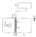
- FIG. 1shows a diagrammatic side view of a film-based radiographic or autoradiographic imaging system.
- FIG. 2shows a diagrammatic side view of a sample object stage and the phosphor screen of the film-based radiographic or autoradiographic imaging system of FIG. 1 .
- FIG. 3shows a work flow diagram in accordance with a method of the present invention, in which film is used to capture images.
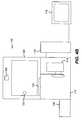
- FIG. 4Ashows a diagrammatic side view of a digital radiographic or autoradiographic imaging system in accordance with the present invention.
- FIG. 4Bshows a diagrammatic front view of the imaging system of FIG. 4A .
- FIG. 5shows a perspective view of the imaging system of FIGS. 4A and 4B .
- FIG. 6shows a diagrammatic side view of the sample object stage of digital radiographic or autoradiographic imaging system of FIGS. 4A , 4 B and 5 .
- FIG. 7shows a work flow diagram in accordance with a method of the present invention in which a digital camera is used to capture images.
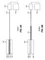
- FIG. 8Ashows a diagrammatic side view of the sample object stage of FIG. 6 wherein the phosphor screen is positioned for imaging MODE 1 .
- FIG. 8Bshows a diagrammatic side view of the sample object stage of FIG. 6 wherein the phosphor screen is positioned for imaging MODE 2 .
- FIGS. 9A and 9Bshow a work flow diagram in accordance with a method of the present invention in which a digital camera is used to capture images.
- FIG. 10shows a work flow diagram of another embodiment in accordance with a method of the present invention.
- FIG. 11shows a diagrammatic side view of another embodiment of the sample object stage and the phosphor screen of the digital radiographic or autoradiographic imaging system of FIGS. 4A and 4B .
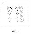
- FIG. 12is a diagrammatic view of an image evaluation insert of a digital stereotactic breast biopsy accreditation phantom.
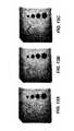
- FIG. 13Ais a single digital radiographic image of the image evaluation insert of FIG. 12 captured with a stationary phosphor screen for the sake of reference.
- FIG. 13Bis the image average of a plurality of (specifically sixteen) digital radiographic images of the image evaluation insert of FIG. 12 captured with a stationary phosphor screen for the sake of reference.
- FIG. 13Cis the image average of a plurality of (specifically sixteen) digital radiographic images of the image evaluation insert of FIG. 12 captured with an incrementally displaced phosphor screen using the system and method in accordance with the present invention.
- FIG. 14Ais a blow-up showing section H of the image evaluation insert of the image shown in FIG. 13A .
- FIG. 14Bis a blow-up showing section H of the image evaluation insert of the image average shown in FIG. 13B .
- FIG. 14Cis a blow-up showing section H of the image evaluation insert of the image average shown in FIG. 13C .
- FIG. 15is a graphical representation of the results of measurements of Groups E, F, G and H of the image evaluation insert of FIG. 12 acquired by the system and method in accordance with the present invention.
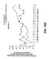
- FIG. 16is another graphical representation of the results of measurements of Groups E, F, G and H of the image evaluation insert of FIG. 12 acquired by the system and method in accordance with the present invention.
- FIG. 1illustrates a film-based radiographic or autoradiographic imaging system 10 comprising an X-ray source 20 , used only for radiography, positioned opposite a sample object stage 30 .
- a radiography or autoradiography film cassette 40is located on the opposite side of stage 30 from source 20 in a film compartment 50 .
- a phosphor screen 60is located between stage 30 and cassette 40 .
- a support frame 70locates and supports stage 30 , screen 60 and cassette 40 .
- a linear motion device 80is operatively connected to screen 60 by a connecting rod 90 .
- a computer control system 95is provided to control device 80 and X-ray source 20 , when the source is activated for radiographic imaging and deactivated for autoradiographic imaging.
- source 20may be turned on and off by system 95 as needed during or following capture of an individual image or series of images.
- FIG. 2shows a diagrammatic side view of sample object stage 30 .
- phosphor screen 60is positioned beneath sample object stage 30 .
- Film cassette 40is positioned beneath screen 60 , which is slideably mounted for motion in a plane parallel to sample object stage 30 and film cassette 40 .
- Phosphor screen 60is slideable in the direction of arrow A relative to frame 70 and in approximate contact with film cassette 40 .
- Linear motion device 80may be a linear induction motor connected to phosphor screen 60 via a connecting rod 90 .
- FIG. 3illustrates an embodiment of a method performed by imaging system 10 in accordance with the invention.
- a subjectsuch as a mouse in an immobilized state (not shown) is placed on object stage 30 in step 200 .
- a series of individual images of the subjectis acquired using phosphor screen 60 in steps 210 , 230 and 250 .
- Image capturemay be achieved (i) with a single film that is multiply exposed at different incremental positions of screen 60 or (ii) with multiple films exposed in series at different incremental positions of screen 60 .
- source 20is turned off and phosphor screen 60 is displaced by device 80 by a distance “d” in steps 220 and 240 , so as to facilitate reduction of phosphor screen mottle.
- This distance “d”is larger than the phosphor grain size (typically between 1 and 20 ⁇ m) but smaller than the difference between the physical size of the phosphor screen 60 and the field of view of each image on the film in cassette 40 .
- the position of screen 60 for each imageis indicated by D 1 , D 2 , D 3 . . . Dn in FIG. 4 .
- the time between each image taken at D 1 , D 2 , D 3 . . . Dn, while source 20 is off,should exceed the time required for the phosphorescence to decay to a sufficiently low level (e.g., 1% after 1.5 sec for terbium-doped gadolinium oxysulfide) to achieve a desired dynamic range.
- the effect of the displacement of the phosphor screen between imagesresults in the blurring of the phosphor screen mottle when the multiply-exposed film is processed in step 260 .
- the phosphor screenmay be moved during the capture of an individual image, and the source 20 may be turned off during movement of the screen.
- the source of radiationis within the subject and cannot be turned on or off; so, a mechanical shutter, not illustrated, must be provided to prevent radiation from the subject from reaching the film while the phosphor screen is being moved.
- FIGS. 4A , 4 B and 5show an electronic, digital radiographic or autoradiographic imaging system 100 , used for high spatial resolution radiography or autoradiography, including an X-ray source 102 and a sample object stage 104 .
- Imaging system 100may be a multimodal type of imaging system such as a KODAK In-Vivo Imaging System FX Pro.
- This type of multimodal optical, radiographic and autoradiographic imaging system 100in addition to the X-ray source 102 , may have a programmable multispectral light source 106 with fiberoptic bundles 108 for illumination delivery, an optical compartment 110 , a lens and camera system 114 , and a communication/computer control system 116 with a display device 118 , for example, a computer monitor.
- Sample object stage 104is disposed within a sample environment 120 , which allows access to the object being imaged.
- sample environment 120is light-tight and fitted with light-locked gas ports for environmental control.
- environmental controlmight be desirable for controlled radiographic imaging or for support of particular specimens.
- Imaging system 100can include an access means or member 122 to provide convenient, safe and light-tight access to sample environment 120 .
- Access meansare well known to those skilled in the art and can include a door, opening, labyrinth, and the like.
- sample environment 120is preferably adapted to provide atmospheric control for sample maintenance or soft X-ray transmission (e.g., temperature/humidity/alternative gases and the like).
- Environmental controlenables practical radiographic contrast below 8 KeV (air absorption) and aids in life support for biological specimens.
- FIG. 6illustrates an embodiment of digital imaging system 100 of FIGS. 4A , 4 B and 5 .
- a phosphor screen or plate 124is slideably mounted for motion in a plane parallel to sample object stage 104 .
- Stage 104includes a rectangular frame 126 to support and stretch a thin plastic support sheet 128 selected so as to support the weight of a sample.
- Sheet 128is optically clear and free of significant interfering fluorescence.
- phosphor screen 124is mounted for translation in the direction of arrow A relative to frame 126 , in intimate contact with support sheet 128 supporting an object to be imaged.
- a linear motion device 130such as a linear induction motor is connected to phosphor screen 124 via a connecting rod 132 and controlled by system 116 .
- FIG. 7illustrates an embodiment of a method performed by system 100 .
- a subjectsuch as a mouse in an immobilized state (not shown) is placed on object stage 104 in step 300 .
- a series of individual radiographic images of the subjectis acquired using phosphor screen 124 in steps 310 , 330 and 350 .
- Source 102may be turned off between images or left on from image to image. During autoradiographic imaging, the source of radiation is within the subject and cannot be turned on or off; so, an electrical or mechanical shutter in lens and camera system 114 , not illustrated, must be used to prevent radiation from the subject from reaching the sensor of the camera while the phosphor screen is being moved.
- phosphor screen 124is displaced by device 130 by a small distance “d” in steps 320 and 340 .
- This distance “d”is larger than the phosphor grain size but smaller than the difference between the physical size of the phosphor screen 124 and the field of view of the images.
- the position of screen 124 for each imageis indicated by D 1 , D 2 , D 3 . . . Dn in FIG. 6 .
- Dnshould exceed the time required for the phosphorescence to decay to a sufficiently low level (e.g., 1% after 1.5 sec for terbium-doped gadolinium oxysulfide) to achieve a desired dynamic range.
- the resultant digital imagesare then pixelwise averaged mathematically, using techniques familiar to those skilled in the art of digital image processing, so as to blur the phosphor screen mottle in step 360 .
- the phosphor screenmay be moved during the capture of an individual image, and the source 102 may be turned off during movement of the screen.
- image capturemay occur during an interval when the film or digital camera or other imaging device captures light from the phosphor screen under (i) on-off control of the camera or imaging device or (ii) on-off control of X-ray source 102 .
- image capturecould be controlled by a combination of camera and X-ray source control.
- the digital radiographic or autoradiographic imaging system 100 of FIGS. 4A , 4 B and 5is used in the multimodal imaging system mode.
- imaging system 100is capable of analytical imaging of objects such as small mammals, insects, fish, seeds, biopsies in differing modes, including bright-field, dark-field (e.g., luminescence and fluorescence), and radiographic or autoradiographic modes.
- FIGS. 8A , 8 B and the workflow of FIGS. 9A and 9Ba method of the invention is illustrated in FIGS. 8A , 8 B and the workflow of FIGS. 9A and 9B .
- the immobilized subject(mouse) in positioned on object stage 104 in step 400 .
- Phosphor screen 124is moved by device 130 into position for digital radiographic or autoradiographic imaging MODE 1 in step 410 , where it is in an overlapping, proximate arrangement with sample object stage 104 .
- a series of individual images of the subjectis acquired in steps 420 , 440 and 460 .
- phosphor screen 124is displaced by a distance “d” by device 130 in steps 430 and 450 .
- Distance “d”is larger than the phosphor grain size but smaller than the difference between the physical size of the phosphor screen 124 and the field of view of the images.
- Linear motion device 130may be controlled by the communication and computer control system 116 .
- the position for each imagefor example is indicated by D 1 , D 2 , D 3 . . . Dn in FIG. 6 .
- the time between each image taken at D 1 , D 2 , D 3 . . . Dnshould exceed the decay time of the phosphor material in the screen.
- the imagesare then averaged so as to blur the phosphor screen mottle in step 470 .
- the phosphor screen 124then is moved in step 480 out of the image path into position for optical imaging MODE 2 and optical images including bright-field and dark-field (e.g. luminescence and fluorescence) images are acquired in step 490 .
- bright-field and dark-fielde.g. luminescence and fluorescence
- Still another embodiment of the inventionconcerns a method for producing a high-resolution digital image from a sequence of low-resolution digital images using a super-resolution technique.
- an immobilized object and cameramay be incrementally displaced with respect to each other during capture of a sequence of low-resolution digital images and the phosphor screen may also be displaced, incoherently from the displacement of the object and camera, for each of the low-resolution digital images by a distance larger than the phosphor grain size and smaller than the difference between the physical size of the phosphor screen and the field of view of the images, so as to blur the phosphor screen mottle.
- the workflow shown in FIG. 10describes a method of obtaining a high resolution radiographic or autoradiographic image with reduced or eliminated screen mottle using the system illustrated in FIGS. 4A , 4 B, and 11 .
- a high-resolution digital imageis computed from a sequence of low-resolution digital images using a super-resolution technique.
- Such a super-resolution techniqueis disclosed in detail in previously mentioned U.S. Patent Application Publication No. 2007/0217713, the disclosure of which is incorporated by reference into this specification.
- the immobilized object on sample object stage 104 and camera 114are incrementally displaced with respect to each other via linear motion devices 130 a and 130 b controlled by the computer 116 during capture of the sequence of low-resolution digital images in step 500 .
- phosphor screen 124is also displaced via linear motion device 130 controlled by the computer 116 by the distance “d”, larger than the phosphor grain size and smaller than the difference between the physical size of the phosphor screen 124 and the field of view of the images.
- Phosphor screen 124is displaced in a manner uncorrelated with the displacement of camera 114 and object stage 104 , for each of the low-resolution digital images, so as to blur the phosphor screen mottle in step 510 .
- a high-resolution digital imageis then computed in step 520 in accordance with the published application by using a data fidelity penalty term, where the data fidelity penalty term is an L 1 norm penalty term to enforce similarities between low-resolution data and a high-resolution image estimate using a spatial penalty term, where the spatial penalty term is a penalty term to encourage sharp edges in the high-resolution image.
- the data fidelity penalty termis an L 1 norm penalty term to enforce similarities between low-resolution data and a high-resolution image estimate using a spatial penalty term, where the spatial penalty term is a penalty term to encourage sharp edges in the high-resolution image.
- FIG. 12is a diagrammatic view of an image evaluation insert of a digital stereotactic breast biopsy accreditation phantom, such as Nuclear Associates Model 18-250.
- the insertis made of wax and contains test objects to simulate indications of breast cancer.
- Nylon fibers A, B, C and D of varying diametersimulate tissue fibrillar extensions in adipose tissue.
- Lens-shaped masses I, J, K and L of varying thicknesssimulate tumor-like masses.
- FIG. 13Ais a single digital radiographic image of the image evaluation insert of FIG. 12 captured with a stationary phosphor screen for the sake of reference.
- FIG. 13Bis the image average of a plurality of (specifically sixteen) digital radiographic images of the image evaluation insert of FIG. 12 captured with a stationary phosphor screen for the sake of reference.
- FIG. 13Cis the image average of a plurality of (specifically sixteen) digital radiographic images of the image evaluation insert of FIG. 12 captured with an incrementally displaced phosphor screen using the system and method of FIGS. 4 to 7 in accordance with the present invention.
- FIG. 14Ais a blow-up of image evaluation insert section H (see FIG. 12 ) of the image shown in FIG. 13A .
- Alumina specks 600 and phosphor screen defects 610are visible.
- FIG. 14Bis a blow-up of image evaluation insert section H of the image average shown in FIG. 13B .
- FIG. 14Cis a blow-up of image evaluation insert section H of the image average shown in FIG. 13C .
- FIGS. 14Ais a blow-up of image evaluation insert section H (see FIG. 12 ) of the image shown in FIG. 13A .
- Alumina specks 600 and phosphor screen defects 610are visible.
- FIG. 14Bis a blow-up of image evaluation insert section H of the image average shown in FIG. 13B .
- FIG. 14Cis a blow-up of image evaluation insert section H of the image average shown in FIG. 13C .
- FIGS. 13CThe comparison of FIGS.
- 14 A,B, and Cshows that the visual impact of the mottle in the background of the specks is reduced by averaging a plurality of images, and is reduced further by averaging a plurality of images wherein the phosphor screen is incrementally displaced compared to averaging a plurality of images wherein the phosphor screen is stationary. Furthermore, artifacts due to phosphor screen defects, such as those apparent in FIGS. 14A and B, are reduced by a great proportion by averaging a plurality of images wherein the phosphor screen is incrementally displaced.
- FIG. 15is a graphical representation of the results of measurements of the image evaluation insert of FIG. 12 acquired by the system and method of FIGS. 4 to 7 in accordance with the present invention. Graphs are shown for Groups E, F, G and H comparing a quantitative figure-of-merit for the detection of the specks plotted against the number of images included in the image average for each of the four sections of differently sized specks, for images captured with an incrementally displaced phosphor screen and a stationary phosphor screen.
- the figure-of-meritis the ratio of the signal, defined as the negative of the sum of the digital counts in each pixel within a region of interest around each speck after the median value of the digital counts in the pixels on the perimeter of the region of interest has been subtracted from the digital count value in each pixel within the region of interest, to the standard deviation of the digital counts in each pixel on the perimeter of the region of interest.
- the datashow that the figure-of-merit generally increases (i.e., improves) with increasing number of images included in the image average, and furthermore that the figure-of-merit generally increases faster for the incrementally displaced phosphor screen compared to the stationary phosphor screen.
- the datais so noisy that only the incrementally displaced phosphor screen exhibits a marked improvement in the figure-of-merit after a substantial number of images have been included in the image average.
- FIG. 16is another graphical representation of the results of measurements of the image evaluation insert of FIG. 12 acquired by the system and method of FIGS. 4 to 7 in accordance with the present invention.
- FIG. 16shows the denominators used in the figures-of-merit plotted in FIG. 15 , namely the standard deviation of the digital counts in each pixel on the perimeter of the region of interest.
- the datashow that the standard deviation of the digital counts in each pixel on the perimeter of the region of interest generally decreases (i.e., improves) with increasing number of images included in the image average, and furthermore that the standard deviation of the digital counts in each pixel on the perimeter of the region of interest generally decreases faster for the incrementally displaced phosphor screen compared to the stationary phosphor screen.
Landscapes
- Health & Medical Sciences (AREA)
- Life Sciences & Earth Sciences (AREA)
- Engineering & Computer Science (AREA)
- Medical Informatics (AREA)
- Biophysics (AREA)
- Physics & Mathematics (AREA)
- Animal Behavior & Ethology (AREA)
- Veterinary Medicine (AREA)
- Public Health (AREA)
- Pathology (AREA)
- General Health & Medical Sciences (AREA)
- Biomedical Technology (AREA)
- Heart & Thoracic Surgery (AREA)
- Molecular Biology (AREA)
- Surgery (AREA)
- High Energy & Nuclear Physics (AREA)
- Radiology & Medical Imaging (AREA)
- Optics & Photonics (AREA)
- Nuclear Medicine, Radiotherapy & Molecular Imaging (AREA)
- Computer Vision & Pattern Recognition (AREA)
- Measurement Of Radiation (AREA)
- Apparatus For Radiation Diagnosis (AREA)
- Image Processing (AREA)
Abstract
Description
- 10 film-based radiographic or autoradiographic imaging system
- 20 X-ray source
- 30 sample object stage
- 40 X-ray film cassette
- 50 film compartment
- 60 phosphor screen or plate
- 70 support frame
- 80 linear motion device
- 90 connecting rod
- 95 computer control system
- 100 radiographic or radioisotopic imaging system
- 102 X-ray source
- 104 sample object stage
- 106 programmable multispectral light source
- 108 fiber optic bundles
- 110 optical compartment
- 114 lens and camera system
- 116 communication and computer control system
- 118 display device
- 120 sample environment
- 122 access means/member
- 124 phosphor screen or plate
- 126 frame
- 128 sheet
- 130 linear motion device
- 132 connecting rod
- 200-520 steps of inventive methods
- 600 alumina specks
- 610 phosphor screen defects
Claims (30)
Priority Applications (5)
| Application Number | Priority Date | Filing Date | Title |
|---|---|---|---|
| US12/324,092US8203132B2 (en) | 2005-09-08 | 2008-11-26 | Apparatus and method for imaging ionizing radiation |
| EP09707728.3AEP2238511A4 (en) | 2008-01-30 | 2009-01-23 | Apparatus and method for imaging ionizing radiation |
| CA2709188ACA2709188C (en) | 2008-01-30 | 2009-01-23 | Apparatus and method for imaging ionizing radiation |
| CN2009801040145ACN101932974B (en) | 2008-01-30 | 2009-01-23 | Apparatus and method for imaging ionizing radiation |
| PCT/US2009/000457WO2009099526A2 (en) | 2008-01-30 | 2009-01-23 | Apparatus and method for imaging ionizing radiation |
Applications Claiming Priority (3)
| Application Number | Priority Date | Filing Date | Title |
|---|---|---|---|
| US11/221,530US7734325B2 (en) | 2004-09-21 | 2005-09-08 | Apparatus and method for multi-modal imaging |
| US2462108P | 2008-01-30 | 2008-01-30 | |
| US12/324,092US8203132B2 (en) | 2005-09-08 | 2008-11-26 | Apparatus and method for imaging ionizing radiation |
Related Parent Applications (1)
| Application Number | Title | Priority Date | Filing Date |
|---|---|---|---|
| US11/221,530Continuation-In-PartUS7734325B2 (en) | 2004-09-21 | 2005-09-08 | Apparatus and method for multi-modal imaging |
Publications (2)
| Publication Number | Publication Date |
|---|---|
| US20090114860A1 US20090114860A1 (en) | 2009-05-07 |
| US8203132B2true US8203132B2 (en) | 2012-06-19 |
Family
ID=40952593
Family Applications (1)
| Application Number | Title | Priority Date | Filing Date |
|---|---|---|---|
| US12/324,092Expired - Fee RelatedUS8203132B2 (en) | 2005-09-08 | 2008-11-26 | Apparatus and method for imaging ionizing radiation |
Country Status (5)
| Country | Link |
|---|---|
| US (1) | US8203132B2 (en) |
| EP (1) | EP2238511A4 (en) |
| CN (1) | CN101932974B (en) |
| CA (1) | CA2709188C (en) |
| WO (1) | WO2009099526A2 (en) |
Cited By (2)
| Publication number | Priority date | Publication date | Assignee | Title |
|---|---|---|---|---|
| US20180206810A1 (en)* | 2017-01-23 | 2018-07-26 | Samsung Electronics Co., Ltd. | X-ray imaging apparatus and control method thereof |
| US11207048B2 (en)* | 2016-12-21 | 2021-12-28 | Samsung Electronics Co., Ltd. | X-ray image capturing apparatus and method of controlling the same |
Families Citing this family (1)
| Publication number | Priority date | Publication date | Assignee | Title |
|---|---|---|---|---|
| US11341629B2 (en)* | 2020-07-02 | 2022-05-24 | Pratt & Whitney Canada Corp. | Systems and methods for generating an inspection image of an object from radiographic imaging |
Citations (99)
| Publication number | Priority date | Publication date | Assignee | Title |
|---|---|---|---|---|
| US1609703A (en) | 1923-03-21 | 1926-12-07 | Ig Farbenindustrie Ag | X-ray photography |
| US3717764A (en) | 1969-03-07 | 1973-02-20 | Fuji Photo Film Co Ltd | Intensifying screen for radiograph use |
| US3936644A (en) | 1974-03-14 | 1976-02-03 | General Electric Company | Multi-layer X-ray screens |
| US4028550A (en) | 1975-12-22 | 1977-06-07 | E. I. Du Pont De Nemours And Company | X-ray screens |
| US4088894A (en) | 1976-12-13 | 1978-05-09 | General Electric Company | (Ba,Sr)F, (Cl,Br) : Eu+2 X-Ray image converters utilizing LaOBr (Tm,Tb) phosphors |
| US4107070A (en) | 1976-11-29 | 1978-08-15 | Eastman Kodak Company | Process for improving the properties of oxysulfide phosphor materials |
| US4208470A (en) | 1978-11-03 | 1980-06-17 | General Electric Company | X-ray intensifying screen |
| US4232227A (en) | 1977-09-30 | 1980-11-04 | Siemens Aktiengesellschaft | X-ray examination apparatus |
| JPS5817544U (en) | 1981-07-27 | 1983-02-03 | ソフテツクス株式会社 | Television device for observing soft X-ray images and solid images |
| US4394737A (en) | 1979-07-11 | 1983-07-19 | Fuji Photo Film Co., Ltd. | Method of processing radiographic image |
| US4446365A (en) | 1979-03-22 | 1984-05-01 | University Of Texas System | Electrostatic imaging method |
| US4675529A (en) | 1984-03-31 | 1987-06-23 | Olympus Optical Co., Ltd. | Fluorescent spectral analysis apparatus |
| US4710637A (en) | 1986-02-10 | 1987-12-01 | Eastman Kodak Company | High efficiency fluorescent screen pair for use in low energy X radiation imaging |
| US4829188A (en) | 1986-10-06 | 1989-05-09 | Nichia Kagaku Kogyo K.K. | Phosphor materials for radiation intensifying screens and radiation intensifying screens containing the phosphor materials |
| US4870279A (en) | 1988-06-20 | 1989-09-26 | General Electric Company | High resolution X-ray detector |
| US4891527A (en) | 1988-08-09 | 1990-01-02 | General Electric Company | Spherical phosphor aggregates, their preparation and use in X-ray screens |
| JPH0231144A (en) | 1988-07-21 | 1990-02-01 | Mitsubishi Electric Corp | Printed circuit board inspection equipment |
| US4898175A (en) | 1986-12-26 | 1990-02-06 | Olympus Optical Co., Ltd. | Out-body observing apparatus |
| JPH0252246A (en) | 1988-08-15 | 1990-02-21 | Tokyo Electron Ltd | X-ray inspection equipment |
| US5069982A (en) | 1990-11-19 | 1991-12-03 | E. I. Du Pont De Nemours And Company | Mixed phosphor x-ray intensifying screens with improved resolution |
| US5307804A (en) | 1991-02-21 | 1994-05-03 | Richard Wolf Gmbh | Endoscope having a camera coupled thereto |
| US5501225A (en) | 1991-09-20 | 1996-03-26 | Wilson; David F. | Imaging of tissue oxygen using needle phosphorimeter |
| US5534709A (en) | 1993-10-07 | 1996-07-09 | Fujitsu Limited | Radiation image reading apparatus |
| US5650135A (en) | 1994-07-01 | 1997-07-22 | The Board Of Trustees Of The Leland Stanford Junior University | Non-invasive localization of a light-emitting conjugate in a mammal |
| US5663005A (en) | 1995-08-08 | 1997-09-02 | Agfa-Gevaert, N.V. | Self-supporting or supported phosphor screen or panel |
| JPH09309845A (en) | 1996-05-21 | 1997-12-02 | Hamamatsu Photonics Kk | Near-infrared fluorescent tracer and fluorescent imaging |
| US5717791A (en) | 1994-11-10 | 1998-02-10 | Agfa-Gevaert | Image contrast enhancing method |
| US5730701A (en) | 1995-09-12 | 1998-03-24 | Olympus Optical Co., Ltd. | Endoscope |
| US5748768A (en) | 1992-10-30 | 1998-05-05 | Kabushiki Kaisha Toshiba | Method and apparatus for correcting distortion in an imaging system |
| US5830629A (en) | 1995-11-01 | 1998-11-03 | Eastman Kodak Company | Autoradiography assemblage using transparent screen |
| JPH11244220A (en) | 1998-03-03 | 1999-09-14 | Fuji Photo Film Co Ltd | Fluorescent endoscope |
| US6227704B1 (en) | 1999-09-30 | 2001-05-08 | Siemens Corporate Research, Inc. | Laser-based method for aligning apparatus for superimposing X-ray and video images |
| US6229873B1 (en) | 1999-09-30 | 2001-05-08 | Siemens Corporate Research, Inc | Method for aligning an apparatus for superimposing X-ray and video images |
| EP1111625A2 (en) | 1999-12-20 | 2001-06-27 | Eastman Kodak Company | Electronic imaging screen with optical interference coating |
| US6269177B1 (en) | 1997-12-01 | 2001-07-31 | Agfa-Gevaert | Method for reconstructing radiation image of a body from partial radiation images |
| US6268613B1 (en)* | 1999-03-02 | 2001-07-31 | Phormax Corporation | Multiple-head phosphor screen scanner |
| US20010012386A1 (en) | 1997-01-31 | 2001-08-09 | Luc Struye | Method for readout of a stimulable phosphor screen |
| US6278765B1 (en) | 1999-12-30 | 2001-08-21 | Leonard Berliner | Process for producing diagnostic quality x-ray images from a fluoroscopic sequence |
| JP2001299786A (en) | 2000-04-18 | 2001-10-30 | Kyoko Oguchi | Small animal restricting implement for obtaining radiograph |
| US6346707B1 (en) | 1996-05-23 | 2002-02-12 | Eastman Kodak Company | Electronic imaging system for autoradiography |
| US6379044B1 (en) | 1999-11-11 | 2002-04-30 | Agfa-Gevaert | Radiographic image recording method and apparatus |
| US6416800B1 (en) | 2000-08-04 | 2002-07-09 | Pearl Technology Holdings, Llc | Fiber optic candy |
| US6424750B1 (en) | 1996-11-29 | 2002-07-23 | Varian Medical Systems, Inc. | Multiple mode digital X-ray imaging system |
| US6447163B1 (en) | 1999-09-30 | 2002-09-10 | Siemens Corporate Research, Inc. | Method for aligning and superimposing X-ray and video images |
| US6459094B1 (en) | 2000-12-20 | 2002-10-01 | Eastman Kodak Company | Method for stitching partial radiation images to reconstruct a full image |
| US6473489B2 (en) | 1999-09-30 | 2002-10-29 | Siemens Corporate Research, Inc | Apparatus for superimposition of X-ray and video images |
| US6495812B1 (en) | 2000-08-02 | 2002-12-17 | Li-Cor, Inc. | Apparatus and method for analyzing an object of interest having a pivotably movable source and detector |
| US20030011701A1 (en) | 2001-07-13 | 2003-01-16 | David Nilson | Multi-view imaging apparatus |
| JP2003028995A (en) | 2001-07-10 | 2003-01-29 | Fuji Photo Film Co Ltd | Radiation image conversion panel |
| US6531225B1 (en) | 1998-06-18 | 2003-03-11 | Hamamatsu Photonics K.K. | Scintillator panel and radiation image sensor |
| EP1304070A2 (en) | 2001-10-19 | 2003-04-23 | Siemens Aktiengesellschaft | Imaging method and device, in particular for small animals |
| US6615063B1 (en) | 2000-11-27 | 2003-09-02 | The General Hospital Corporation | Fluorescence-mediated molecular tomography |
| US20030187344A1 (en) | 2002-02-22 | 2003-10-02 | Xenogen Corporation | Bottom fluorescence illumination assembly for an imaging apparatus |
| US20030211158A1 (en) | 2002-03-29 | 2003-11-13 | Frechet Jean M.J. | Microgel particles for the delivery of bioactive materials |
| US20040004193A1 (en) | 2002-02-22 | 2004-01-08 | Xenogen Corporation | Fluorescence illumination assembly for an imaging apparatus |
| US6686200B1 (en) | 1993-08-31 | 2004-02-03 | Uab Research Foundation | Methods and compositions for the large scale production of recombinant adeno-associated virus |
| JP2004121289A (en) | 2002-09-30 | 2004-04-22 | Aloka Co Ltd | X-ray ct apparatus, radiation measurement apparatus, and container for small animal |
| US20040089817A1 (en) | 2002-11-11 | 2004-05-13 | Long William F. | Method and apparatus for time resolved optical imaging of biological tissues as part of animals |
| US6762420B2 (en) | 1998-06-18 | 2004-07-13 | Hamamatsu Photonics K.K. | Organic film vapor deposition method and a scintillator panel |
| WO2004081865A2 (en) | 2003-03-10 | 2004-09-23 | University Of Iowa Research Foundation | Systems and methods for bioliminescent computed tomographic reconstruction |
| US20040199067A1 (en) | 2003-01-10 | 2004-10-07 | Deutsches Krebsforschungszentrum Stiftung Des Offentlichen Rechts | Method and apparatus for detecting the position and the orientation of an interventional device |
| US20040202360A1 (en) | 2003-04-11 | 2004-10-14 | Besson Guy M. | Scatter rejection for composite medical imaging systems |
| WO2004089204A1 (en) | 2003-04-03 | 2004-10-21 | Siemens Corporate Research, Inc. | Real-time acquisition of co-registered x-ray and optical images |
| WO2004108902A2 (en) | 2003-06-04 | 2004-12-16 | Visen Medical, Inc. | Biocompatible fluorescent silicon nanoparticles |
| US20050028482A1 (en) | 2003-07-01 | 2005-02-10 | Xenogen Corporation | Multi-mode internal imaging |
| JP2005049341A (en) | 2003-07-04 | 2005-02-24 | Agfa Gevaert Nv | Image storage phosphor or scintillator panel coated onto flexible support |
| WO2005027730A2 (en) | 2003-09-19 | 2005-03-31 | The General Hospital Corporation | Fluorescence polarization imaging devices and methods |
| US20050122529A1 (en) | 2003-12-05 | 2005-06-09 | Korea Advanced Institute Of Science And Technology | Measurement system of three-dimensional shape of transparent thin film using acousto-optic tunable filter |
| JP2005164577A (en) | 2003-10-24 | 2005-06-23 | Agfa Gevaert Nv | Stimulable phosphor screen/panel and manufacture control for it |
| US20050148846A1 (en) | 2000-02-25 | 2005-07-07 | Xenogen Corporation | Imaging apparatus |
| US20050175538A1 (en) | 2003-10-20 | 2005-08-11 | Xenogen Corporation | Small animal light intensity monitor |
| US6948502B2 (en) | 2002-05-09 | 2005-09-27 | Mayo Foundation For Medical Education And Research | Method and apparatus for positioning a forearm for imaging and analysis |
| US20050237423A1 (en) | 2001-07-13 | 2005-10-27 | Xenogen Corporation | Structured light imaging apparatus |
| EP1619548A2 (en) | 2000-03-01 | 2006-01-25 | Fuji Photo Film Co., Ltd. | Image scanning apparatus |
| US20060064000A1 (en) | 2004-09-21 | 2006-03-23 | Vizard Douglas L | Apparatus and method for multi-modal imaging |
| US20060111613A1 (en) | 2004-09-30 | 2006-05-25 | Boston Scientific Scimed, Inc. | Selectively rotatable shaft coupler |
| US20060118742A1 (en) | 2004-12-06 | 2006-06-08 | Richard Levenson | Systems and methods for in-vivo optical imaging and measurement |
| US20060173354A1 (en) | 2003-02-05 | 2006-08-03 | Vasilis Ntziachristos | Method and system for free space optical tomography of diffuse media |
| US20060210135A1 (en) | 2005-03-07 | 2006-09-21 | Fuji Photo Film Co., Ltd. | Method and apparatus for correcting radiographic images |
| US20060293396A1 (en) | 2005-01-14 | 2006-12-28 | Eastman Kodak Company | Amine polymer-modified nanoparticulate carriers |
| US20070016077A1 (en) | 2004-12-08 | 2007-01-18 | Masaya Nakaoka | Fluorescent endoscope device |
| US20070063154A1 (en) | 2005-02-02 | 2007-03-22 | Wei Chen | Energy-transfer nanocomposite materials and methods of making and using same |
| WO2007032940A2 (en) | 2005-09-12 | 2007-03-22 | Rutgers, The State University Of New Jersey Office Of Corporate Liaison And Technology Transfer | System and methods for generating three-dimensional images from two-dimensional bioluminescence images and visualizing tumor shapes and locations |
| US20070087445A1 (en) | 2005-10-14 | 2007-04-19 | The General Hospital Corporation | Arrangements and methods for facilitating photoluminescence imaging |
| US20070217713A1 (en) | 2004-12-16 | 2007-09-20 | Peyman Milanfar | Robust reconstruction of high resolution grayscale images from a sequence of low resolution frames |
| US20070238957A1 (en) | 2005-12-22 | 2007-10-11 | Visen Medical, Inc. | Combined x-ray and optical tomographic imaging system |
| US20070238656A1 (en) | 2006-04-10 | 2007-10-11 | Eastman Kodak Company | Functionalized poly(ethylene glycol) |
| US20070281322A1 (en) | 2006-05-22 | 2007-12-06 | Lumencor, Inc. | Bioanalytical instrumentation using a light source subsystem |
| US20080045797A1 (en) | 2004-07-02 | 2008-02-21 | Osaka University | Endoscope Attachment And Endoscope |
| US20080049893A1 (en) | 2006-08-25 | 2008-02-28 | Karlheinz Bartzke | Rotary device for an optic tomography and optic tomography with a rotating device |
| US7338651B2 (en) | 2001-09-04 | 2008-03-04 | Texas Tech University System | Multi-use multimodal imaging chelates |
| US7394053B2 (en) | 2004-09-09 | 2008-07-01 | Beth Israel Deaconess Medical Center, Inc. | Systems and methods for multi-modal imaging having a spatial relationship in three dimensions between first and second image data |
| US7406967B2 (en) | 2003-02-05 | 2008-08-05 | Callaway James J | Universal intravenous arm support |
| US20080197296A1 (en) | 2007-02-20 | 2008-08-21 | Minoru Uematsu | Particle beam irradiation system |
| US20080281322A1 (en) | 2007-05-11 | 2008-11-13 | Ablation Frontiers, Inc. | RF Energy Delivery System and Method |
| US20090086908A1 (en) | 2005-09-08 | 2009-04-02 | John William Harder | Apparatus and method for multi-modal imaging using nanoparticle multi-modal imaging probes |
| US20090159805A1 (en) | 2005-09-08 | 2009-06-25 | Gilbert Feke | Apparatus and method for multi-modal imaging |
| US20090238434A1 (en) | 2008-03-24 | 2009-09-24 | Gilbert Feke | Method for reproducing the spatial orientation of an immobilized subject in a multi-modal imaging system |
| US20100022866A1 (en) | 2005-09-08 | 2010-01-28 | Gilbert Feke | Torsional support apparatus and method for craniocaudal rotation of animals |
Family Cites Families (4)
| Publication number | Priority date | Publication date | Assignee | Title |
|---|---|---|---|---|
| JP2627087B2 (en)* | 1989-10-18 | 1997-07-02 | 富士写真フイルム株式会社 | Breast energy subtraction device |
| US20030034458A1 (en)* | 2001-03-30 | 2003-02-20 | Fuji Photo Film Co., Ltd. | Radiation image storage panel |
| US7037640B2 (en)* | 2003-07-04 | 2006-05-02 | Agfa-Gevaert | Image storage phosphor or scintillator panels coated onto flexible supports |
| EP1805532A1 (en)* | 2004-10-29 | 2007-07-11 | Orex Computed Radiography Ltd. | Method and apparatus for reading out an image from a storage phosphor sheet |
- 2008
- 2008-11-26USUS12/324,092patent/US8203132B2/ennot_activeExpired - Fee Related
- 2009
- 2009-01-23EPEP09707728.3Apatent/EP2238511A4/ennot_activeWithdrawn
- 2009-01-23CACA2709188Apatent/CA2709188C/ennot_activeExpired - Fee Related
- 2009-01-23WOPCT/US2009/000457patent/WO2009099526A2/enactiveApplication Filing
- 2009-01-23CNCN2009801040145Apatent/CN101932974B/ennot_activeExpired - Fee Related
Patent Citations (107)
| Publication number | Priority date | Publication date | Assignee | Title |
|---|---|---|---|---|
| US1609703A (en) | 1923-03-21 | 1926-12-07 | Ig Farbenindustrie Ag | X-ray photography |
| US3717764A (en) | 1969-03-07 | 1973-02-20 | Fuji Photo Film Co Ltd | Intensifying screen for radiograph use |
| US3936644A (en) | 1974-03-14 | 1976-02-03 | General Electric Company | Multi-layer X-ray screens |
| US4028550A (en) | 1975-12-22 | 1977-06-07 | E. I. Du Pont De Nemours And Company | X-ray screens |
| US4107070A (en) | 1976-11-29 | 1978-08-15 | Eastman Kodak Company | Process for improving the properties of oxysulfide phosphor materials |
| US4088894A (en) | 1976-12-13 | 1978-05-09 | General Electric Company | (Ba,Sr)F, (Cl,Br) : Eu+2 X-Ray image converters utilizing LaOBr (Tm,Tb) phosphors |
| US4232227A (en) | 1977-09-30 | 1980-11-04 | Siemens Aktiengesellschaft | X-ray examination apparatus |
| US4208470A (en) | 1978-11-03 | 1980-06-17 | General Electric Company | X-ray intensifying screen |
| US4446365A (en) | 1979-03-22 | 1984-05-01 | University Of Texas System | Electrostatic imaging method |
| US4394737A (en) | 1979-07-11 | 1983-07-19 | Fuji Photo Film Co., Ltd. | Method of processing radiographic image |
| JPS5817544U (en) | 1981-07-27 | 1983-02-03 | ソフテツクス株式会社 | Television device for observing soft X-ray images and solid images |
| US4675529A (en) | 1984-03-31 | 1987-06-23 | Olympus Optical Co., Ltd. | Fluorescent spectral analysis apparatus |
| US4710637A (en) | 1986-02-10 | 1987-12-01 | Eastman Kodak Company | High efficiency fluorescent screen pair for use in low energy X radiation imaging |
| US4829188A (en) | 1986-10-06 | 1989-05-09 | Nichia Kagaku Kogyo K.K. | Phosphor materials for radiation intensifying screens and radiation intensifying screens containing the phosphor materials |
| US4898175A (en) | 1986-12-26 | 1990-02-06 | Olympus Optical Co., Ltd. | Out-body observing apparatus |
| US4870279A (en) | 1988-06-20 | 1989-09-26 | General Electric Company | High resolution X-ray detector |
| JPH0231144A (en) | 1988-07-21 | 1990-02-01 | Mitsubishi Electric Corp | Printed circuit board inspection equipment |
| US4891527A (en) | 1988-08-09 | 1990-01-02 | General Electric Company | Spherical phosphor aggregates, their preparation and use in X-ray screens |
| JPH0252246A (en) | 1988-08-15 | 1990-02-21 | Tokyo Electron Ltd | X-ray inspection equipment |
| US5069982A (en) | 1990-11-19 | 1991-12-03 | E. I. Du Pont De Nemours And Company | Mixed phosphor x-ray intensifying screens with improved resolution |
| US5307804A (en) | 1991-02-21 | 1994-05-03 | Richard Wolf Gmbh | Endoscope having a camera coupled thereto |
| US5501225A (en) | 1991-09-20 | 1996-03-26 | Wilson; David F. | Imaging of tissue oxygen using needle phosphorimeter |
| US5748768A (en) | 1992-10-30 | 1998-05-05 | Kabushiki Kaisha Toshiba | Method and apparatus for correcting distortion in an imaging system |
| US6686200B1 (en) | 1993-08-31 | 2004-02-03 | Uab Research Foundation | Methods and compositions for the large scale production of recombinant adeno-associated virus |
| US5534709A (en) | 1993-10-07 | 1996-07-09 | Fujitsu Limited | Radiation image reading apparatus |
| US5650135A (en) | 1994-07-01 | 1997-07-22 | The Board Of Trustees Of The Leland Stanford Junior University | Non-invasive localization of a light-emitting conjugate in a mammal |
| US5717791A (en) | 1994-11-10 | 1998-02-10 | Agfa-Gevaert | Image contrast enhancing method |
| US5663005A (en) | 1995-08-08 | 1997-09-02 | Agfa-Gevaert, N.V. | Self-supporting or supported phosphor screen or panel |
| US5730701A (en) | 1995-09-12 | 1998-03-24 | Olympus Optical Co., Ltd. | Endoscope |
| US5830629A (en) | 1995-11-01 | 1998-11-03 | Eastman Kodak Company | Autoradiography assemblage using transparent screen |
| JPH09309845A (en) | 1996-05-21 | 1997-12-02 | Hamamatsu Photonics Kk | Near-infrared fluorescent tracer and fluorescent imaging |
| US6346707B1 (en) | 1996-05-23 | 2002-02-12 | Eastman Kodak Company | Electronic imaging system for autoradiography |
| US6424750B1 (en) | 1996-11-29 | 2002-07-23 | Varian Medical Systems, Inc. | Multiple mode digital X-ray imaging system |
| US20010012386A1 (en) | 1997-01-31 | 2001-08-09 | Luc Struye | Method for readout of a stimulable phosphor screen |
| US6269177B1 (en) | 1997-12-01 | 2001-07-31 | Agfa-Gevaert | Method for reconstructing radiation image of a body from partial radiation images |
| JPH11244220A (en) | 1998-03-03 | 1999-09-14 | Fuji Photo Film Co Ltd | Fluorescent endoscope |
| US6531225B1 (en) | 1998-06-18 | 2003-03-11 | Hamamatsu Photonics K.K. | Scintillator panel and radiation image sensor |
| US6762420B2 (en) | 1998-06-18 | 2004-07-13 | Hamamatsu Photonics K.K. | Organic film vapor deposition method and a scintillator panel |
| US6268613B1 (en)* | 1999-03-02 | 2001-07-31 | Phormax Corporation | Multiple-head phosphor screen scanner |
| US6227704B1 (en) | 1999-09-30 | 2001-05-08 | Siemens Corporate Research, Inc. | Laser-based method for aligning apparatus for superimposing X-ray and video images |
| US6473489B2 (en) | 1999-09-30 | 2002-10-29 | Siemens Corporate Research, Inc | Apparatus for superimposition of X-ray and video images |
| US6447163B1 (en) | 1999-09-30 | 2002-09-10 | Siemens Corporate Research, Inc. | Method for aligning and superimposing X-ray and video images |
| US6229873B1 (en) | 1999-09-30 | 2001-05-08 | Siemens Corporate Research, Inc | Method for aligning an apparatus for superimposing X-ray and video images |
| US6379044B1 (en) | 1999-11-11 | 2002-04-30 | Agfa-Gevaert | Radiographic image recording method and apparatus |
| US6444988B1 (en) | 1999-12-20 | 2002-09-03 | Eastman Kodak Company | Electronic imaging screen with optical interference coating |
| EP1111625A2 (en) | 1999-12-20 | 2001-06-27 | Eastman Kodak Company | Electronic imaging screen with optical interference coating |
| JP2001255607A (en) | 1999-12-20 | 2001-09-21 | Eastman Kodak Co | Electronic image pickup screen device having optical interference film |
| US6278765B1 (en) | 1999-12-30 | 2001-08-21 | Leonard Berliner | Process for producing diagnostic quality x-ray images from a fluoroscopic sequence |
| US20050148846A1 (en) | 2000-02-25 | 2005-07-07 | Xenogen Corporation | Imaging apparatus |
| EP1619548A2 (en) | 2000-03-01 | 2006-01-25 | Fuji Photo Film Co., Ltd. | Image scanning apparatus |
| JP2001299786A (en) | 2000-04-18 | 2001-10-30 | Kyoko Oguchi | Small animal restricting implement for obtaining radiograph |
| US6495812B1 (en) | 2000-08-02 | 2002-12-17 | Li-Cor, Inc. | Apparatus and method for analyzing an object of interest having a pivotably movable source and detector |
| US6416800B1 (en) | 2000-08-04 | 2002-07-09 | Pearl Technology Holdings, Llc | Fiber optic candy |
| US6615063B1 (en) | 2000-11-27 | 2003-09-02 | The General Hospital Corporation | Fluorescence-mediated molecular tomography |
| US6459094B1 (en) | 2000-12-20 | 2002-10-01 | Eastman Kodak Company | Method for stitching partial radiation images to reconstruct a full image |
| JP2003028995A (en) | 2001-07-10 | 2003-01-29 | Fuji Photo Film Co Ltd | Radiation image conversion panel |
| US7113217B2 (en) | 2001-07-13 | 2006-09-26 | Xenogen Corporation | Multi-view imaging apparatus |
| US20050237423A1 (en) | 2001-07-13 | 2005-10-27 | Xenogen Corporation | Structured light imaging apparatus |
| US20030011701A1 (en) | 2001-07-13 | 2003-01-16 | David Nilson | Multi-view imaging apparatus |
| US7338651B2 (en) | 2001-09-04 | 2008-03-04 | Texas Tech University System | Multi-use multimodal imaging chelates |
| EP1304070A2 (en) | 2001-10-19 | 2003-04-23 | Siemens Aktiengesellschaft | Imaging method and device, in particular for small animals |
| US20030082104A1 (en) | 2001-10-19 | 2003-05-01 | Thomas Mertelmeier | Imaging method and imaging apparatus, in particular for small animal imaging |
| US20030187344A1 (en) | 2002-02-22 | 2003-10-02 | Xenogen Corporation | Bottom fluorescence illumination assembly for an imaging apparatus |
| US20040004193A1 (en) | 2002-02-22 | 2004-01-08 | Xenogen Corporation | Fluorescence illumination assembly for an imaging apparatus |
| US20030211158A1 (en) | 2002-03-29 | 2003-11-13 | Frechet Jean M.J. | Microgel particles for the delivery of bioactive materials |
| US6948502B2 (en) | 2002-05-09 | 2005-09-27 | Mayo Foundation For Medical Education And Research | Method and apparatus for positioning a forearm for imaging and analysis |
| JP2004121289A (en) | 2002-09-30 | 2004-04-22 | Aloka Co Ltd | X-ray ct apparatus, radiation measurement apparatus, and container for small animal |
| US20040089817A1 (en) | 2002-11-11 | 2004-05-13 | Long William F. | Method and apparatus for time resolved optical imaging of biological tissues as part of animals |
| US20040199067A1 (en) | 2003-01-10 | 2004-10-07 | Deutsches Krebsforschungszentrum Stiftung Des Offentlichen Rechts | Method and apparatus for detecting the position and the orientation of an interventional device |
| US7406967B2 (en) | 2003-02-05 | 2008-08-05 | Callaway James J | Universal intravenous arm support |
| US20060173354A1 (en) | 2003-02-05 | 2006-08-03 | Vasilis Ntziachristos | Method and system for free space optical tomography of diffuse media |
| US20040249260A1 (en) | 2003-03-10 | 2004-12-09 | Ge Wang | Systems and methods for bioluminescent computed tomographic reconstruction |
| WO2004081865A2 (en) | 2003-03-10 | 2004-09-23 | University Of Iowa Research Foundation | Systems and methods for bioliminescent computed tomographic reconstruction |
| WO2004089204A1 (en) | 2003-04-03 | 2004-10-21 | Siemens Corporate Research, Inc. | Real-time acquisition of co-registered x-ray and optical images |
| US7198404B2 (en) | 2003-04-03 | 2007-04-03 | Siemens Medical Solutions Usa, Inc. | Real-time acquisition of co-registered X-ray and optical images |
| US20040202360A1 (en) | 2003-04-11 | 2004-10-14 | Besson Guy M. | Scatter rejection for composite medical imaging systems |
| WO2004108902A2 (en) | 2003-06-04 | 2004-12-16 | Visen Medical, Inc. | Biocompatible fluorescent silicon nanoparticles |
| US20050028482A1 (en) | 2003-07-01 | 2005-02-10 | Xenogen Corporation | Multi-mode internal imaging |
| US7190991B2 (en) | 2003-07-01 | 2007-03-13 | Xenogen Corporation | Multi-mode internal imaging |
| JP2005049341A (en) | 2003-07-04 | 2005-02-24 | Agfa Gevaert Nv | Image storage phosphor or scintillator panel coated onto flexible support |
| WO2005027730A2 (en) | 2003-09-19 | 2005-03-31 | The General Hospital Corporation | Fluorescence polarization imaging devices and methods |
| US20050175538A1 (en) | 2003-10-20 | 2005-08-11 | Xenogen Corporation | Small animal light intensity monitor |
| JP2005164577A (en) | 2003-10-24 | 2005-06-23 | Agfa Gevaert Nv | Stimulable phosphor screen/panel and manufacture control for it |
| US20050122529A1 (en) | 2003-12-05 | 2005-06-09 | Korea Advanced Institute Of Science And Technology | Measurement system of three-dimensional shape of transparent thin film using acousto-optic tunable filter |
| US20080045797A1 (en) | 2004-07-02 | 2008-02-21 | Osaka University | Endoscope Attachment And Endoscope |
| US7394053B2 (en) | 2004-09-09 | 2008-07-01 | Beth Israel Deaconess Medical Center, Inc. | Systems and methods for multi-modal imaging having a spatial relationship in three dimensions between first and second image data |
| US7734325B2 (en) | 2004-09-21 | 2010-06-08 | Carestream Health, Inc. | Apparatus and method for multi-modal imaging |
| US20060064000A1 (en) | 2004-09-21 | 2006-03-23 | Vizard Douglas L | Apparatus and method for multi-modal imaging |
| US20060111613A1 (en) | 2004-09-30 | 2006-05-25 | Boston Scientific Scimed, Inc. | Selectively rotatable shaft coupler |
| US20060118742A1 (en) | 2004-12-06 | 2006-06-08 | Richard Levenson | Systems and methods for in-vivo optical imaging and measurement |
| US20070016077A1 (en) | 2004-12-08 | 2007-01-18 | Masaya Nakaoka | Fluorescent endoscope device |
| US20070217713A1 (en) | 2004-12-16 | 2007-09-20 | Peyman Milanfar | Robust reconstruction of high resolution grayscale images from a sequence of low resolution frames |
| US20060293396A1 (en) | 2005-01-14 | 2006-12-28 | Eastman Kodak Company | Amine polymer-modified nanoparticulate carriers |
| US20070063154A1 (en) | 2005-02-02 | 2007-03-22 | Wei Chen | Energy-transfer nanocomposite materials and methods of making and using same |
| US20060210135A1 (en) | 2005-03-07 | 2006-09-21 | Fuji Photo Film Co., Ltd. | Method and apparatus for correcting radiographic images |
| US20090086908A1 (en) | 2005-09-08 | 2009-04-02 | John William Harder | Apparatus and method for multi-modal imaging using nanoparticle multi-modal imaging probes |
| US20100022866A1 (en) | 2005-09-08 | 2010-01-28 | Gilbert Feke | Torsional support apparatus and method for craniocaudal rotation of animals |
| US20090159805A1 (en) | 2005-09-08 | 2009-06-25 | Gilbert Feke | Apparatus and method for multi-modal imaging |
| WO2007032940A2 (en) | 2005-09-12 | 2007-03-22 | Rutgers, The State University Of New Jersey Office Of Corporate Liaison And Technology Transfer | System and methods for generating three-dimensional images from two-dimensional bioluminescence images and visualizing tumor shapes and locations |
| US20070087445A1 (en) | 2005-10-14 | 2007-04-19 | The General Hospital Corporation | Arrangements and methods for facilitating photoluminescence imaging |
| US20070238957A1 (en) | 2005-12-22 | 2007-10-11 | Visen Medical, Inc. | Combined x-ray and optical tomographic imaging system |
| US20070238656A1 (en) | 2006-04-10 | 2007-10-11 | Eastman Kodak Company | Functionalized poly(ethylene glycol) |
| US20070281322A1 (en) | 2006-05-22 | 2007-12-06 | Lumencor, Inc. | Bioanalytical instrumentation using a light source subsystem |
| US20080049893A1 (en) | 2006-08-25 | 2008-02-28 | Karlheinz Bartzke | Rotary device for an optic tomography and optic tomography with a rotating device |
| US20080197296A1 (en) | 2007-02-20 | 2008-08-21 | Minoru Uematsu | Particle beam irradiation system |
| US20080281322A1 (en) | 2007-05-11 | 2008-11-13 | Ablation Frontiers, Inc. | RF Energy Delivery System and Method |
| US20090238434A1 (en) | 2008-03-24 | 2009-09-24 | Gilbert Feke | Method for reproducing the spatial orientation of an immobilized subject in a multi-modal imaging system |
Non-Patent Citations (48)
| Title |
|---|
| "Monomolecular Multimodal Fluorescence-Radiosotope Imaging Agents", Bioconjugate Chemistry, 16(5), pp. 1232-1239, 2005. |
| Alyautdin et al., Delivery of Loperamide Across the Blood-Brain Barrier with Polysorbate 80-Coated Polybutylcyanoacrylate Nanoparticles, Pharmaceutical Research, vol. 14, No. 3, 1997, pp. 325-328. |
| Am. Assoc. Phys. Med., "MicroCT scanner performance and considerations for vascular specimen imaging", by Michael Marxen et al., Med. Phys. 31 (2), Feb. 2004, pp. 305-313. |
| Biochem Biophys Res Commun, Inspiration for Life Science, "Anti Human Galectin 3 Polyelonal Antibody", by W. Zhu, 280:11831188, 2001, 2 pages. |
| Burke et al., Acid-Base Equilibria of Weak Polyelectrolytes in Multilayer Thin Films, Langmuir, 2003, vol. 19, No. 8, pp. 3297-3303. |
| Cleare et al., "An Experimental Study of the Mottle Produced by X-Ray Intensifying Screens," The Am. J. of Roent. and Rad. Physics, vol. 88, No. 1, pp. 168-174, Jul. 1962. |
| Corresponding CN = CN 200580031808.5-SIPO First Office Action dated Dec. 4, 2009. 14 pages. |
| Corresponding WO = PCT/us2005/032504, International Preliminary Report on Patentability, dated Mar. 27, 2007, 8 pages. |
| CosmoBio report, Mar. 2004, No. 43, "Kodak Image Station 2000MM". (English translation of p. 18-5 pages). |
| CosmoBio report, Mar. 2004, No. 43, "Kodak Image Station 2000MM". (JP language-Foreign, 13 pages). |
| Da Silva et al., ScienceDirect, Nuclear Instruments and Methods in Physics Research, Design of a small animal multiomodality tomographer for X-ray and optical coupling: Theory and experiments, 2007, pp. 118-121. |
| De Verdiè, et al., Reversion of multidrug resistence with polyalkycyanoacrylate nanoparticles: towards a mechanism of action, BJC British Journal of Cancer, 1997, vol. 76 (2), pp. 198-205. |
| EP Sear Report, Application No. EP10012074, dated Apr. 18, 2011, 2 pages. |
| G. Kwon et al., Block copolymer micelles as long-circulating drug vehicles, Advanced Drug Delivery Reviews, vol. 16, 1995, pp. 295-309. |
| G. Volkheimer, Ubersicht, Persorption von Mikropartikeln, Pathologies, 1993, vol. 14, pp. 247-252. |
| Hamamatsu Photonics K.K., Catalog No. SFAS0017E06, X-Ray Line Scan Camera, Jun. 2010, 4 pages. |
| Hamamatsu Photonics K.K., Publication No. TMCP1031E04, X-Ray Scinitllator, Jun. 2009, 4 pages. |
| Harlow et al., Antibodies-A Laboratory Manual, Chapter 5-Immunizations, 1988, pp. 91-113. |
| Hrkach et al., Nanotechnology for biomaterials engineering; structural characterization of amphiphilic polymeric nanoparticles by 1H NMR spectroscopy, Biomaterials, vol. 18, No. 1, 1997, pp. 27-30. |
| Hussain et al., Enhanced Oral Uptake of Tomato Lectin-Conjugated Nanoparticles in the Rat, Pharmaceutical Research, vol. 14, No. 5, 1997, pp. 613-618. |
| IEEE Transactions on Nuclear Science, "Iodine 125 Imaging in Mice Using Nal(TI)/Flat Panel PMT Integral Assembly", by M.N. Cinti et al., vol. 54, No. 3, Jun. 2007, pp. 461-468. |
| International Search Report, International Application No. PCT/US2005/032504, dated Dec. 23, 2005. |
| International Search Report, International Application No. PCT/US2008/010304, dated Dec. 8, 2008. |
| International Search Report, International Application No. PCT/US2009/000457, dated Aug. 21, 2009. |
| Kodak Image Station 2000MM Multi-Modal Imager, Kodak Scientific Imaging Systems-advertisment-Fall/2003 (2 pages). |
| Kodak Image Station 2000MM Multimodal Imaging System, Internet web address: http://www.kodak.com/US/en/health/scientific/products/imgstation2000MM/index.shtml-Sep. 16, 2004. (1 page). |
| Köhler et al., Derivation of specific antibody-producing tissue culture and tumor lines by cell fusion, Medical Research Council Laboratory of Molecular Biology, Cambridge, Eur. J. Immunol., 1976, vol. 6, pp. 511-519. |
| Kruger et al., HYPR-spectral photoacoustic CT for preclinical imaging, Photons Plus Ultrasound Imaging and Sensing 2009, Proc. Of SPIE, vol. 7177, 10 pages. |
| Labhasetwar et al., Nanoparticle drug delivery system for restenosis, Advanced Drug Delivery Reviews, vol. 24, 1997, pp. 63-85. |
| LoBuglio et al., Mouse/human chimeric conoclonal antibody in man: Kinetics and immune response, Proc. Natl. Acad. Sci., vol. 86, Jun. 1989 Immunology, pp. 4220-4224. |
| Mat. Res. Soc. Symp. Proc., "Optimising of the Physico-Chemical Properties of a Novel Barium Sulphate Preparation for the X-Ray Examination Of The Intestine", by Barbara Laermann et al., vol. 550, 1999 Materials Research Society, pp. 59-64. |
| Moghimi et al., Nanomedicine: current status and future prospects, The FASEB Journal, vol. 19, Mar. 2005, pp. 311-330. |
| Nature Methods, "Harnessing multimodality to enhance quantification and reproducibility of in vivo molecular imaging data", by Gilbert D. Feke et al., Nov. 2008, 2 pages. |
| P. Mitchell, "Picture Perfect: Imaging Gives Biomarkers New Look", Pharma DD, vol. 1, No. 3, pp. 1-5 (2006). |
| Proceedings of the American Thoracic Society, "Micro-Computed Tomography of the Lungs and Pulmonary-Vascular System", by Erik L. Ritman, 2 pages 477-480, 2005. |
| Rat Atlas Project, Internet Study: Hubei Bioinformatics and Molecular Imaging Key Laboratory, The Key Laboratory of Biomedical Photonics of Ministry of Education, College of Life Science and Technology, Huazhong University of Science and Technology, http://www.vch.org.cn/mice/method.aspx, printed from Internet on Sep. 12, 2011, (4 pages). |
| Research Takes Many Directions, Science, vol. 303, No. 5657, Jan. 23, 2004. Advertisement (2 pages). |
| Sage, Linda, "The Bare Bones of Animal Imaging", The Scientist, vol. 19, Issue 4, Feb. 28, 2005. (4 pages). |
| Sharma et al., Novel Taxol® Formulation: Polyvinylpyrrolidone Nanoparticle-Encapsulated Taxol® for Drug Delivery in Cancer Therapy, Oncology Research, vol. 8, Nos. 7/8, pp. 281-286, 1986. |
| Soukchareun et al., Preparation and Characterization of Antisense Oligonucleotide-Peptide Hybrids Containing Viral Fusion Peptides, Bioconjugate Chem, 1995, vol. 6, pp. 43-53. |
| The Journal of Nuclear Medicine, "Significance of Incidental 18F-FDG Accumulations in the Gastrointestical Tract in PET/CT: Correlation with Endoscopic and Histopathologic Results", by Ehab M. Kamel et al., vol. 45, No. 11, pp. 1804-1810, 2004. |
| User's Guide for KODAK Image Station 2000MM, Nov. 2003 (168 pages). |
| User's Guide for KODAK Imagst Station 2000R, Aug. 2002, (172 pages). |
| V.P. Torchilin, Polymer-coated long-circulating microparticulate pharmaceuticals, J. Microencapsulation, 1998, vol. 15, No. 1, pp. 1-19. |
| Virostko et al., Molecular Imaging, vol. 3, No. 4, Oct. 2004, pp. 333-342, Factors Influencing Quantification of in Vivo Bioluminescence Imaging: Application to Assessment of Pancreatic Islet Transplants. |
| Winter et al., Man-made antibodies, Nature-vol. 349, Jan. 24, 1991, pp. 293-299. |
| Y. Kwon et al., Enhanced antigen presentation and immunostimulation of dendritic cells using acid-degradable cationic nanoparticles, Journal of Controlled Release 105, 2005, pp. 199-212. |
| Zobel et al., Cationic Polyhexylcyanoacrylate Nanoparticles as Carriers for Antisense Oligonucleotides, Antisense & Nucleic Acid Drug Development, vol. 7, 1997, pp. 483-493. |
Cited By (3)
| Publication number | Priority date | Publication date | Assignee | Title |
|---|---|---|---|---|
| US11207048B2 (en)* | 2016-12-21 | 2021-12-28 | Samsung Electronics Co., Ltd. | X-ray image capturing apparatus and method of controlling the same |
| US20180206810A1 (en)* | 2017-01-23 | 2018-07-26 | Samsung Electronics Co., Ltd. | X-ray imaging apparatus and control method thereof |
| US10849589B2 (en)* | 2017-01-23 | 2020-12-01 | Samsung Electronics Co., Ltd. | X-ray imaging apparatus and control method thereof |
Also Published As
| Publication number | Publication date |
|---|---|
| CN101932974B (en) | 2013-09-04 |
| CA2709188C (en) | 2016-08-30 |
| CA2709188A1 (en) | 2009-08-13 |
| CN101932974A (en) | 2010-12-29 |
| WO2009099526A2 (en) | 2009-08-13 |
| US20090114860A1 (en) | 2009-05-07 |
| WO2009099526A3 (en) | 2009-10-15 |
| EP2238511A2 (en) | 2010-10-13 |
| EP2238511A4 (en) | 2014-07-23 |
Similar Documents
| Publication | Publication Date | Title |
|---|---|---|
| Huda et al. | Comparison of a photostimulable phosphor system with film for dental radiology | |
| US6934409B2 (en) | PCI radiation image processing apparatus | |
| JP5394640B2 (en) | Apparatus and method for multimode imaging | |
| US6415049B1 (en) | Apparatus for detecting and processing a radiation image | |
| KR20090031728A (en) | Apparatus for asymmetric dual-screen digital radiography | |
| US20210199603A1 (en) | System and method for colorizing a radiograph from cabinet x-ray systems | |
| US7412111B2 (en) | Enhanced image processing method for the presentation of digitally-combined medical images | |
| JP2003180670A (en) | Digital phase-contrasted x-ray imaging system | |
| JP2002065653A (en) | Radiography apparatus, method and program relating to control with respect to the same apparatus | |
| US8203132B2 (en) | Apparatus and method for imaging ionizing radiation | |
| Schaefer-Prokop et al. | Digital radiography of the chest: detector techniques and performance parameters | |
| Chavarria et al. | X-ray imaging detector for radiological applications adapted to the context and requirements of low-and middle-income countries | |
| EP1086651B1 (en) | Apparatus and method for x-ray imaging | |
| EP1886629A1 (en) | Digital radiation image capturing system | |
| EP2407106A1 (en) | Method of determining the spatial response signature of a detector in computed radiography | |
| JP2001311701A (en) | Roentgenogram radiographing method and its radiographing device | |
| CN101103925A (en) | X-ray photography device | |
| Seibert et al. | Cassette-based digital mammography | |
| RU85292U1 (en) | DEVICE FOR X-RAY DIAGNOSTIC RESEARCHES OF GRAIN AND SEEDS | |
| Pisano et al. | Perspective on digital mammography | |
| KR101129369B1 (en) | Tomograph | |
| Yaffe | Development of full field digital mammography | |
| JP2002085389A (en) | X-ray imaging system and method | |
| US20050074092A1 (en) | Digital x-ray camera for quality evaluation three-dimensional topographic reconstruction of single crystals | |
| US20060259245A1 (en) | Digital X-ray Camera for Quality Evaluation Three-Dimensional Topographic Reconstruction of Single Crystals of Biological Macromolecules |
Legal Events
| Date | Code | Title | Description |
|---|---|---|---|
| AS | Assignment | Owner name:CARESTREAM HEALTH, INC., NEW YORK Free format text:ASSIGNMENT OF ASSIGNORS INTEREST;ASSIGNORS:FEKE, GILBERT;WOOD, DOUGLAS O.;VIZARD, DOULGAS L.;REEL/FRAME:022131/0577 Effective date:20090108 | |
| AS | Assignment | Owner name:CREDIT SUISSE AG, CAYMAN ISLANDS BRANCH, NEW YORK Free format text:INTELLECTUAL PROPERTY SECURITY AGREEMENT;ASSIGNORS:CARESTREAM HEALTH, INC.;CARESTREAM DENTAL, LLC;QUANTUM MEDICAL IMAGING, L.L.C.;AND OTHERS;REEL/FRAME:026269/0411 Effective date:20110225 | |
| AS | Assignment | Owner name:CARESTREAM HEALTH, INC., NEW YORK Free format text:RELEASE OF SECURITY INTEREST IN INTELLECTUAL PROPERTY (SECOND LIEN);ASSIGNOR:CREDIT SUISSE AG, CAYMAN ISLANDS BRANCH;REEL/FRAME:027851/0812 Effective date:20110225 | |
| STCF | Information on status: patent grant | Free format text:PATENTED CASE | |
| AS | Assignment | Owner name:BRUKER BIOSPIN CORPORATION, MASSACHUSETTS Free format text:ASSIGNMENT OF ASSIGNORS INTEREST;ASSIGNOR:CARESTREAM HEALTH, INC.;REEL/FRAME:029142/0234 Effective date:20120926 | |
| FPAY | Fee payment | Year of fee payment:4 | |
| SULP | Surcharge for late payment | ||
| MAFP | Maintenance fee payment | Free format text:PAYMENT OF MAINTENANCE FEE, 8TH YEAR, LARGE ENTITY (ORIGINAL EVENT CODE: M1552); ENTITY STATUS OF PATENT OWNER: LARGE ENTITY Year of fee payment:8 | |
| AS | Assignment | Owner name:TROPHY DENTAL INC., GEORGIA Free format text:RELEASE BY SECURED PARTY;ASSIGNOR:CREDIT SUISSE AG, CAYMAN ISLANDS BRANCH;REEL/FRAME:061681/0380 Effective date:20220930 Owner name:QUANTUM MEDICAL HOLDINGS, LLC, NEW YORK Free format text:RELEASE BY SECURED PARTY;ASSIGNOR:CREDIT SUISSE AG, CAYMAN ISLANDS BRANCH;REEL/FRAME:061681/0380 Effective date:20220930 Owner name:QUANTUM MEDICAL IMAGING, L.L.C., NEW YORK Free format text:RELEASE BY SECURED PARTY;ASSIGNOR:CREDIT SUISSE AG, CAYMAN ISLANDS BRANCH;REEL/FRAME:061681/0380 Effective date:20220930 Owner name:CARESTREAM DENTAL, LLC, GEORGIA Free format text:RELEASE BY SECURED PARTY;ASSIGNOR:CREDIT SUISSE AG, CAYMAN ISLANDS BRANCH;REEL/FRAME:061681/0380 Effective date:20220930 Owner name:CARESTREAM HEALTH, INC., NEW YORK Free format text:RELEASE BY SECURED PARTY;ASSIGNOR:CREDIT SUISSE AG, CAYMAN ISLANDS BRANCH;REEL/FRAME:061681/0380 Effective date:20220930 | |
| FEPP | Fee payment procedure | Free format text:MAINTENANCE FEE REMINDER MAILED (ORIGINAL EVENT CODE: REM.); ENTITY STATUS OF PATENT OWNER: LARGE ENTITY | |
| LAPS | Lapse for failure to pay maintenance fees | Free format text:PATENT EXPIRED FOR FAILURE TO PAY MAINTENANCE FEES (ORIGINAL EVENT CODE: EXP.); ENTITY STATUS OF PATENT OWNER: LARGE ENTITY | |
| STCH | Information on status: patent discontinuation | Free format text:PATENT EXPIRED DUE TO NONPAYMENT OF MAINTENANCE FEES UNDER 37 CFR 1.362 | |
| FP | Lapsed due to failure to pay maintenance fee | Effective date:20240619 |