US8202335B2 - Superabrasive elements, methods of manufacturing, and drill bits including same - Google Patents
Superabrasive elements, methods of manufacturing, and drill bits including sameDownload PDFInfo
- Publication number
- US8202335B2 US8202335B2US11/899,691US89969107AUS8202335B2US 8202335 B2US8202335 B2US 8202335B2US 89969107 AUS89969107 AUS 89969107AUS 8202335 B2US8202335 B2US 8202335B2
- Authority
- US
- United States
- Prior art keywords
- superabrasive
- tungsten carbide
- polycrystalline diamond
- carbide layer
- volume
- Prior art date
- Legal status (The legal status is an assumption and is not a legal conclusion. Google has not performed a legal analysis and makes no representation as to the accuracy of the status listed.)
- Expired - Fee Related, expires
Links
Images


Classifications
- E—FIXED CONSTRUCTIONS
- E21—EARTH OR ROCK DRILLING; MINING
- E21B—EARTH OR ROCK DRILLING; OBTAINING OIL, GAS, WATER, SOLUBLE OR MELTABLE MATERIALS OR A SLURRY OF MINERALS FROM WELLS
- E21B10/00—Drill bits
- E21B10/46—Drill bits characterised by wear resisting parts, e.g. diamond inserts
- E21B10/56—Button-type inserts
- E21B10/567—Button-type inserts with preformed cutting elements mounted on a distinct support, e.g. polycrystalline inserts
- E21B10/573—Button-type inserts with preformed cutting elements mounted on a distinct support, e.g. polycrystalline inserts characterised by support details, e.g. the substrate construction or the interface between the substrate and the cutting element
- E21B10/5735—Interface between the substrate and the cutting element
- B—PERFORMING OPERATIONS; TRANSPORTING
- B24—GRINDING; POLISHING
- B24D—TOOLS FOR GRINDING, BUFFING OR SHARPENING
- B24D18/00—Manufacture of grinding tools or other grinding devices, e.g. wheels, not otherwise provided for
- B—PERFORMING OPERATIONS; TRANSPORTING
- B24—GRINDING; POLISHING
- B24D—TOOLS FOR GRINDING, BUFFING OR SHARPENING
- B24D3/00—Physical features of abrasive bodies, or sheets, e.g. abrasive surfaces of special nature; Abrasive bodies or sheets characterised by their constituents
- B24D3/02—Physical features of abrasive bodies, or sheets, e.g. abrasive surfaces of special nature; Abrasive bodies or sheets characterised by their constituents the constituent being used as bonding agent
- B24D3/04—Physical features of abrasive bodies, or sheets, e.g. abrasive surfaces of special nature; Abrasive bodies or sheets characterised by their constituents the constituent being used as bonding agent and being essentially inorganic
- B24D3/06—Physical features of abrasive bodies, or sheets, e.g. abrasive surfaces of special nature; Abrasive bodies or sheets characterised by their constituents the constituent being used as bonding agent and being essentially inorganic metallic or mixture of metals with ceramic materials, e.g. hard metals, "cermets", cements
- B24D3/10—Physical features of abrasive bodies, or sheets, e.g. abrasive surfaces of special nature; Abrasive bodies or sheets characterised by their constituents the constituent being used as bonding agent and being essentially inorganic metallic or mixture of metals with ceramic materials, e.g. hard metals, "cermets", cements for porous or cellular structure, e.g. for use with diamonds as abrasives
- Y—GENERAL TAGGING OF NEW TECHNOLOGICAL DEVELOPMENTS; GENERAL TAGGING OF CROSS-SECTIONAL TECHNOLOGIES SPANNING OVER SEVERAL SECTIONS OF THE IPC; TECHNICAL SUBJECTS COVERED BY FORMER USPC CROSS-REFERENCE ART COLLECTIONS [XRACs] AND DIGESTS
- Y10—TECHNICAL SUBJECTS COVERED BY FORMER USPC
- Y10T—TECHNICAL SUBJECTS COVERED BY FORMER US CLASSIFICATION
- Y10T428/00—Stock material or miscellaneous articles
- Y10T428/26—Web or sheet containing structurally defined element or component, the element or component having a specified physical dimension
- Y10T428/263—Coating layer not in excess of 5 mils thick or equivalent
- Y10T428/264—Up to 3 mils
- Y10T428/265—1 mil or less
Definitions
- Wear-resistant compactscomprising superabrasive (i.e., superhard) material are utilized for a variety of applications and in a corresponding variety of mechanical systems.
- wear resistant superabrasive elementsare used in drilling tools (e.g., inserts, cutting elements, gage trimmers, etc.), machining equipment, bearing apparatuses, wire drawing machinery, and in other mechanical systems.
- polycrystalline diamond compactshave found particular utility as cutting elements in drill bits (e.g., roller cone drill bits and fixed cutter drill bits) and as bearing surfaces in so-called “thrust-bearing” apparatuses.
- a polycrystalline diamond compact (“PDC”) cutting element or cuttertypically includes a diamond layer or table formed by a sintering process employing high-temperature and high-pressure conditions that causes the diamond table to become bonded to a substrate (e.g., a cemented tungsten carbide substrate), as described in greater detail below.
- a polycrystalline diamond compactWhen a polycrystalline diamond compact is used as a cutting element, it may be mounted to a drill bit either by press-fitting, brazing, or otherwise coupling the cutting element into a receptacle defined by the drill bit, or by brazing the substrate of the cutting element directly into a preformed pocket, socket, or other receptacle formed in the drill bit.
- cutter pocketsmay be formed in the face of a matrix-type bit comprising tungsten carbide particles that are infiltrated or cast with a binder (e.g., a copper-based binder), as known in the art.
- Such drill bitsare typically used for rock drilling, machining of wear resistant materials, and other operations which require high abrasion resistance or wear resistance.
- a rotary drill bitmay include a plurality of polycrystalline abrasive cutting elements affixed to a drill bit body.
- a PDC(as well as other superhard materials) may be fabricated by placing a layer of diamond crystals or grains adjacent one surface of a substrate and exposing the diamond grains and substrate to an ultra-high pressure and ultra-high temperature (“HPHT”) process.
- HPHTultra-high pressure and ultra-high temperature
- a substrate and adjacent diamond crystal layermay be sintered under ultra-high temperature and ultra-high pressure conditions to cause the diamond crystals or grains to bond to one another.
- a catalystmay be employed for facilitating formation of polycrystalline diamond.
- a so-called “solvent catalyst”may be employed for facilitating the formation of polycrystalline diamond.
- solvent catalystmay be employed for facilitating the formation of polycrystalline diamond.
- cobalt, nickel, and ironare among examples of solvent catalysts for forming polycrystalline diamond.
- solvent catalyst from the substrate bodye.g., cobalt from a cobalt-cemented tungsten carbide substrate
- solvent catalyst from the substrate bodybecomes liquid and sweeps from the region behind the substrate surface next to the diamond powder and into the diamond grains.
- a solvent catalystmay be mixed with the diamond powder prior to sintering, if desired.
- such a solvent catalystmay dissolve carbon at high temperatures. Such carbon may be dissolved from the diamond grains or portions of the diamond grains that graphitize due to the high temperatures of sintering. When the solvent catalyst is cooled, at least a portion of the carbon held in solution may precipitate or otherwise be expelled from the solvent catalyst and may facilitate formation of diamond bonds between adjacent or abutting diamond grains. Thus, the diamond grains become mutually bonded to form a polycrystalline diamond table upon the substrate.
- the solvent catalystmay remain in the diamond layer within the interstitial space between the diamond grains or the solvent catalyst may be at least partially removed and optionally replaced by another material, as known in the art. For instance, the solvent catalyst may be at least partially removed from the polycrystalline diamond by acid leaching.
- a superabrasive volumeincluding a tungsten carbide layer.
- a superabrasive volumemay comprise polycrystalline diamond, cubic boron nitride, diamond, silicon carbide, mixtures of the foregoing, or any composite including one or more of the foregoing materials and/or other superhard materials.
- a tungsten carbide layermay be formed upon at least a portion of superabrasive volume.
- a tungsten carbide layermay be formed upon at least a portion of a substantially planar surface and/or a side surface of the superabrasive volume.
- such a superabrasive volumemay be affixed to a substrate or to a drilling tool.
- a superabrasive element/compact including tungsten carbide layermay be affixed to a drill bit or other drilling tool by brazing or any other suitable method.
- any of the aspects described in this applicationmay be applicable to a polycrystalline diamond element or method of forming or manufacturing a polycrystalline diamond element.
- Subterranean drill bits or other subterranean drilling or reaming tools including at least one of any superabrasive element encompassed by this applicationare also contemplated by the present invention.
- FIG. 1Ashows a perspective view of one embodiment of a superabrasive volume
- FIG. 1Bshows a perspective view of a superabrasive element comprising the superabrasive volume shown in FIG. 1A including a tungsten carbide layer;
- FIG. 2Ashows a perspective view of another embodiment of a superabrasive volume
- FIG. 2Bshows a side cross-sectional view of a superabrasive element comprising the superabrasive volume shown in FIG. 2A including a tungsten carbide layer;
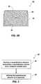
- FIG. 3shows a schematic diagram of one embodiment of a method for forming a superabrasive compact encompassed by the present invention
- FIG. 4shows a schematic diagram of an additional embodiment of a method for forming a superabrasive compact
- FIG. 5shows a side cross-sectional view of one embodiment of a superabrasive compact encompassed by the present invention
- FIG. 6shows a schematic diagram of a further embodiment of a method for forming a superabrasive compact
- FIG. 7shows a side cross-sectional view of an additional embodiment of a superabrasive compact encompassed by the present invention.
- FIG. 8shows a side cross-sectional view of yet a further embodiment of a superabrasive compact encompassed by the present invention
- FIG. 9shows a side cross-sectional view of an additional embodiment of a superabrasive element including a tungsten carbide layer encompassed by the present invention.
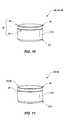
- FIG. 10shows a perspective view of a superabrasive compact encompassed by the present invention
- FIG. 11shows a perspective view of another embodiment of a superabrasive element
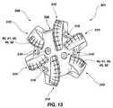
- FIG. 12shows a perspective view of a rotary drill bit including at least one superabrasive cutting element according to the present invention
- FIG. 13shows a top elevation view of the rotary drill bit shown in FIG. 12 ;
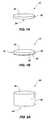
- FIG. 14Ashows an enlarged side cross-sectional view of one embodiment of a rotatable cutting system including a tungsten carbide layer
- FIG. 14Bshows an exploded, partial side cross-sectional view of the cutting element and cutting pocket shown in FIG. 14A ;
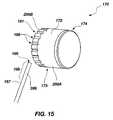
- FIG. 15shows a perspective view an embodiment of an actuator assembly for applying torque to a rotatable cutting element, wherein at least one of the components includes a tungsten carbide layer.
- the present inventionrelates generally to structures comprising at least one superabrasive material (e.g., diamond, boron nitride, silicon carbide, mixtures of the foregoing, or any material exhibiting a hardness exceeding a hardness of tungsten carbide) and methods of manufacturing such structures. Exemplary embodiments and features relating to the present invention are discussed hereinbelow.
- superabrasive materiale.g., diamond, boron nitride, silicon carbide, mixtures of the foregoing, or any material exhibiting a hardness exceeding a hardness of tungsten carbide
- superabrasivemean a material exhibiting a hardness exceeding a hardness of tungsten carbide.
- polycrystalline diamondmay be one embodiment of a superabrasive volume.
- superabrasive materialcomprising a diamond-silicon carbide composite as disclosed in U.S. Pat. No. 7,060,641, the disclosure of which is incorporated herein, in its entirety, by this reference may be employed to form a superabrasive volume. More generally, cubic boron nitride, diamond, silicon carbide, or mixtures or any composite including one or more of the foregoing materials or other superhard materials may be employed.
- the present inventionrelates to a superabrasive mass or volume with a tungsten carbide layer.
- tungsten carbide layermeans a material substantially comprising tungsten carbide (which may be alloyed to a limited extent), wherein the tungsten carbide is not cemented or held in a binder or matrix.
- a tungsten carbide layermay essentially consist of tungsten carbide or may consist entirely of tungsten carbide.
- a tungsten carbide layermay be formed, for instance, by chemical vapor deposition, physical vapor deposition, chemical reactions, sintering (without a binder), or any suitable method.
- a cobalt-cemented tungsten carbide material or a tungsten carbide hardfacing (tungsten carbide particulate applied to a surface with a melted binder) materialis not considered a tungsten carbide layer according to the above definition.
- a superabrasive volume including a tungsten carbide layermay be formed. Further, the superabrasive volume and a substrate may be bonded to one another. Such a method may be employed to form a superabrasive element with desirable characteristics. For instance, in one embodiment, such a process may allow for bonding of a so-called “thermally-stable” product (“TSP”) or thermally-stable polycrystalline diamond (“TSD”) or a partially thermally-stable (i.e., partially leached) polycrystalline diamond volume to a substrate to form a polycrystalline diamond element. In one embodiment, a HPHT process may be employed for bonding the polycrystalline diamond volume to the substrate. Such a polycrystalline diamond element may exhibit a desirable residual stress field and desirable thermal stability characteristics.
- manufacturing sintered superabrasive materialssuch as polycrystalline diamond involves the compression of superhard particles under extremely high pressure. Such compression may occur at room temperature, at least initially, and may result in the reduction of void space in the superhard particles due to brittle crushing, sliding, stacking, and/or otherwise consolidation. Thus, the superhard particles may sustain very high local pressures where they contact one another, but the pressures experienced on non-contacting surfaces of the superhard particles and in the interstitial voids may be, comparatively, low.
- Manufacturing superhard materialsfurther involves heating the superhard particles. Such heating may increase the temperature of the superhard particles from room temperature to facilitate inter-particle bonding (i.e., to a temperature and pressure where the desired superhard material is thermodynamically stable).
- a solvent catalyste.g., cobalt, nickel, iron, etc.
- a solvent catalystmay dissolve and transport carbon between the diamond grains and facilitate diamond formation.
- solvent catalystmay facilitate the formation of diamond-to-diamond bonds in the sintered polycrystalline diamond material, resulting in formation of a coherent skeleton or matrix of bonded diamond particles or grains.
- Other types of catalysts besides metal solvent catalystsmay be employed.
- carbonate-based catalystse.g., magnesium carbonate (MgCO 3 )
- MgCO 3magnesium carbonate
- One aspect of the present inventionrelates to a superabrasive volume including a tungsten carbide layer. More particularly, the present invention contemplates that one embodiment of a method of manufacturing a superabrasive compact may comprise forming a superabrasive volume including a tungsten carbide layer over at least a portion of an exterior surface of the superabrasive volume.
- a tungsten carbide layermay be formed by chemical vapor deposition (“CVD”) or variants thereof (e.g., plasma-enhanced CVD, etc., without limitation).
- CVDchemical vapor deposition
- HARDIDE®a commercially available CVD tungsten carbide layer
- HARDIDE®a commercially available CVD tungsten carbide layer
- a tungsten carbide layermay be formed by physical vapor deposition (“PVD”), variants of PVD, high-velocity oxygen fuel (“HVOF”) thermal spray processes, or any other suitable process, without limitation.
- PVDphysical vapor deposition
- HVOFhigh-velocity oxygen fuel
- the tungsten carbide layermay be formed prior to forming the superabrasive volume.
- a tungsten carbide sheet or filmmay be positioned adjacent to a superabrasive powder (e.g., diamond powder, cubic boron nitride powder, silicon carbide powder, mixtures of the foregoing, etc.) and then the superabrasive powder may be sintered to form a superabrasive volume.
- a tungsten carbide layermay be initially formed and a superabrasive volume may be formed upon the tungsten carbide layer by CVD or any other suitable process.
- FIG. 1Ashows a perspective view of one embodiment of a superabrasive volume 10 .
- superabrasive volume 10may be generally cylindrical and may include upper substantially planar surface 20 , side surface 22 , and lower substantially planar surface 24 .
- superabrasive volume 10may comprise polycrystalline diamond, cubic boron nitride, diamond, silicon carbide, mixtures of the foregoing, or any composite including one or more of the foregoing materials and/or other superhard materials.
- a tungsten carbide layermay be formed upon at least a portion of superabrasive volume 10 .
- FIG. 1Ashows a perspective view of one embodiment of a superabrasive volume 10 .
- FIG. 1Ashows a perspective view of one embodiment of a superabrasive volume 10 .
- superabrasive volume 10may be generally cylindrical and may include upper substantially planar surface 20 , side surface 22 , and lower substantially planar surface 24 .
- superabrasive volume 10may comprise polycrystalline
- FIG. 1Bshows one embodiment of a superabrasive element 12 including a tungsten carbide layer 30 formed upon at least a portion of substantially planar surface 24 .
- Tungsten carbide layer 30may exhibit a thickness of about 5 ⁇ m to about 100 ⁇ m, and more specifically about 5 ⁇ m to about 60 ⁇ m.
- Such a configurationmay allow for superabrasive element 52 to be attached to a drilling tool or other apparatus.
- superabrasive element 52 including tungsten carbide layer 30may be affixed to a drill bit by brazing, since the tungsten carbide layer 30 may be wettable by a brazing alloy.
- tungsten carbide layer 30may be formed upon any portion of substantially planar surface 24 and/or any portion of side surface 22 and/or any portion of substantially planar surface 20 , without limitation.
- any portion over which a tungsten carbide layer is not desiredmay be masked or otherwise precluded from forming the tungsten carbide layer.
- tungsten carbidemay be formed over a selected region (e.g., the entire exterior or a portion thereof) of the superabrasive volume 10 and then selected portions of such tungsten carbide layer may be removed by grinding, electrical-discharge machining, chemical treatments, or any other suitable method, without limitation.
- FIG. 2Ashows another embodiment of a superabrasive volume 50 including an upper substantially planar surface 20 , a side surface 22 , and a lower substantially planar surface 24 .
- superabrasive volume 50may be substantially cylindrical, in one embodiment.
- a tungsten carbide layermay be formed upon at least a portion of superabrasive volume 50 .
- FIG. 2Bshows one embodiment of a superabrasive element 52 including a tungsten carbide layer 30 formed upon substantially planar surface 24 and over a majority of side surface 22 . Such a configuration may allow for superabrasive element 52 to be attached to a drilling tool or other apparatus.
- superabrasive element 52may be affixed to a drill bit by brazing, since the tungsten carbide layer 30 may be wet by a brazing alloy. More generally, the present invention contemplates that tungsten carbide layer 30 may be formed upon any portion of substantially planar surface 24 and/or any portion of side surface 22 and/or any portion of substantially planar surface 20 , without limitation. As described above, tungsten carbide layer 30 may be formed over a selected portion of superabrasive volume 30 via masking, selective removal, or any other suitable method.
- a tungsten carbide layerbonded to a superabrasive material.
- the instant disclosurecontemplates that such a tungsten carbide layer may be bonded directly to a superabrasive material or one or more intermediary layer may extend between the superabrasive material and the tungsten carbide layer.
- an intermediary layer between the superabrasive material and the tungsten carbide layermay comprise tungsten, cobalt, molybdenum, tin, copper, or any metal, ceramic, or other selected material.
- a tungsten carbide layermay include other constituents, such as an alloying material or other element or compound.
- tungsten carbidemay be alloyed with fluorine.
- alternate layers of tungsten and tungsten carbidemay be formed.
- additional layers of a selected materialmay be formed upon a tungsten carbide layer, if desired.
- a method of manufacturing a superabrasive compactmay further comprise affixing a superabrasive volume including a tungsten carbide layer to a substrate.
- a superabrasive volumemay be brazed, soldered, welded (including frictional or inertial welding), or otherwise affixed to a substrate.
- the superabrasive volumemay become affixed to a substrate by exposing the superabrasive volume and substrate to an elevated pressure (i.e., any pressure exceeding an ambient atmospheric pressure; e.g., exceeding about 20 kilobar, at least about 60 kilobar, or between about 20 kilobar and about 60 kilobar) and an elevated temperature (e.g., at least about 1000° Celsius).
- an elevated pressurei.e., any pressure exceeding an ambient atmospheric pressure; e.g., exceeding about 20 kilobar, at least about 60 kilobar, or between about 20 kilobar and about 60 kilobar
- an elevated temperaturee.g., at least about 1000° Celsius
- the superabrasive elementmay be positioned adjacent to a substrate, and the superabrasive element and the substrate may be subjected to a HPHT process.
- a HPHT processincludes developing an elevated pressure and an elevated temperature.
- the phrase “HPHT process”means to generate a pressure of at least about 40 kilobar and a temperature of at least about 1000° Celsius. In one example, a pressure of at least about 60 kilobar may be developed. Regarding temperature, in one example, a temperature of at least about 1,350° Celsius may be developed.
- a HPHT processmay cause the superabrasive element to become affixed to the substrate.
- a braze materialmay be provided to ultimately extend between and affix the superabrasive element and the substrate to one another. Such a braze material may be at least partially melted to affix the superabrasive element to the substrate upon cooling of the braze material.
- a manufacturing method for forming a superabrasive compactmay include forming a superabrasive element comprising a superabrasive volume and a tungsten carbide layer. Further, the superabrasive element may be affixed to a substrate.
- FIG. 3shows a schematic diagram of a method 32 for forming a superabrasive compact. As shown in FIG. 3 , method 32 comprises process action 34 and process action 36 . Particularly, as shown in FIG. 3 , a superabrasive element may be provided (as represented by process action 34 in FIG.
- the superabrasive elementmay be affixed to a substrate (as represented by process action 36 in FIG. 3 ) to form a superabrasive compact.
- a superabrasive elementcomprising a superabrasive volume including a tungsten carbide layer may be positioned adjacent to a substrate and the assembly may be exposed to a HPHT process.
- at least one constituente.g., a metal
- the superabrasive elementmay be affixed to the substrate.
- such a HPHT processmay generate a beneficial residual stress field within each of the superabrasive volume and the substrate.
- a coefficient of thermal expansion of a superabrasive materialmay be substantially less than a coefficient of expansion of a substrate.
- a superabrasive volumemay comprise polycrystalline diamond and a substrate may comprise cobalt-cemented tungsten carbide.
- the present inventioncontemplates that selectively controlling the temperature and/or pressure during a HPHT process may allow for selectively tailoring a residual stress field developed within a superabrasive volume and/or a substrate to which the superabrasive volume is affixed. Furthermore, the presence of a residual stress field developed within the superabrasive and/or the substrate may be beneficial.
- FIG. 4shows a schematic diagram representing another embodiment of a method 38 for forming a superabrasive compact, the method comprising a process action 42 and a process action 46 .
- process action 42may include forming a superabrasive element comprising a superabrasive volume and a tungsten carbide layer.
- the superabrasive elementmay be positioned adjacent to a substrate.
- at least one constituent of the superabrasive element, the substrate, or bothmay be at least partially melted (as represented by process action 46 ). At least partially melting of such at least one constituent may cause the superabrasive element to be affixed or bonded to the substrate.
- Such a method 38may be relatively effective for bonding a superabrasive element to a substrate.
- a superabrasive volumemay comprise a sintered structure formed by a previous HPHT process.
- a superabrasive volumemay comprise a polycrystalline diamond structure (e.g., a diamond table) or any other sintered superabrasive material, without limitation.
- superabrasive volumemay comprise boron nitride, silicon carbide, fullerenes, or a material having a hardness exceeding a hardness of tungsten carbide, without limitation.
- a substratemay comprise a cobalt-cemented tungsten carbide. Accordingly, at elevated temperatures and pressures, such cobalt may at least partially melt and/or infiltrate or wet the superabrasive volume. Upon solidification of the cobalt, the substrate and the superabrasive volume may be affixed to one another.
- FIG. 5shows a side cross-sectional view of a superabrasive compact 40 comprising a superabrasive element 12 , as described herein, bonded to a substrate 110 .
- superabrasive volume 10may comprise polycrystalline diamond and a tungsten carbide layer 30
- substrate 110may comprise a cobalt-cemented tungsten carbide.
- a catalyste.g., cobalt
- a catalyste.g., cobalt
- a catalystmay be at least partially removed from polycrystalline diamond by exposing the polycrystalline diamond to an acid, exposing the polycrystalline diamond to an electrolytic processes, combinations of the foregoing, or any other suitable method.
- FIG. 6shows a further embodiment of a manufacturing method 48 for forming a superabrasive element, the method comprising a process action 54 , process action 56 , and process action 58 .
- process action 54may include forming a superabrasive element comprising a superabrasive volume and a tungsten carbide layer.
- process action 56the superabrasive element and, as represented by process action 58 , the superabrasive element may be brazed to the substrate.
- Exemplary brazesin one example, may be referred to as “Group Ib solvents” (e.g., copper, silver, and gold) and may optionally contain one or more carbide former (e.g., titanium, vanadium, chromium, manganese, zirconium, niobium, molybdenum, technetium, hafnium, tantalum, tungsten, or rhenium, without limitation).
- carbide formere.g., titanium, vanadium, chromium, manganese, zirconium, niobium, molybdenum, technetium, hafnium, tantalum, tungsten, or rhenium, without limitation.
- exemplary compositionsmay include gold-tantalum Au—Ta, silver-copper-titanium (Ag—Cu—Ti), or any mixture of any Group Ib solvent(s) and, optionally, one or more carbide former.
- braze materialsmay include a metal from Group VIII in the periodic table, (e.g., iron, cobalt, and nickel).
- a braze materialmay comprise an alloy of about 4.5% titanium, about 26.7% copper, and about 68.8% silver, otherwise known as TICUSIL®, which is currently commercially available from Wesgo Metals, Hayward, Calif.
- a braze materialmay comprise an alloy of about 25% silver, about 37% copper, about 10% nickel, about 15% palladium, and about 13% manganese, otherwise known as PALNICUROM® 10, which is also currently commercially available from Wesgo Metals, Hayward, Calif.
- a braze materialmay comprise an alloy of about 64% iron and about 36% nickel, commonly referred to as Invar.
- a braze materialmay comprise a single metal such as for example, cobalt.
- a superabrasive volume and at least a portion of a substratemay be sealed within an enclosure under vacuum or an inert atmosphere (e.g., at least substantially surrounded by an inert gas, such as argon, nitrogen, and/or helium, without limitation).
- an inert gassuch as argon, nitrogen, and/or helium, without limitation.
- any methods or systemsmay be employed for sealing, under vacuum or inert atmosphere, a superabrasive volume or element and at least a portion of a substrate within an enclosure.
- U.S. Pat. No. 4,333,902 to Harathe disclosure of which is incorporated, in its entirety, by this reference
- the present inventioncontemplates a braze material may be at least partially melted to affix the substrate to the superabrasive element. Subsequent cooling of the braze material may cause solidification of the braze material, and affixation of the superabrasive element to the substrate via the braze material.
- a superabrasive element, a braze material, and a substratemay be exposed to a HPHT process. Such a HPHT process may cause the superabrasive element to be affixed to the substrate via the braze material.
- a braze material, substrate, and/or superabrasive elementmay be heated to effect affixation of the superabrasive element and the substrate.
- a superabrasive element, a braze material, and a substratemay be exposed to a pressure exceeding an ambient atmospheric pressure (e.g., at least about 60 kilobar). Further, the braze material may be at least partially melted. Optionally, the braze material may be at least partially melted while the elevated pressure is applied to the enclosure.
- a braze materialmay exhibit a melting temperature of at least about 900° Celsius.
- a braze materialmay exhibit a melting temperature of about 900° Celsius in the case of TICUSIL®).
- a braze materialmay exhibit a melting temperature of about 1013° Celsius in the case of PALNICUROM® 10.
- a braze materialmay exhibit a melting temperature of about 1427° Celsius in the case of Invar. In yet a further embodiment, a braze material may exhibit a melting temperature of about 1493° Celsius in the case of cobalt.
- the actual melting temperature of a braze materialis dependent on the pressure applied to the braze material and the composition of the braze material. Accordingly, the values listed above are merely for reference.
- the braze materialmay be at least partially solidified while the enclosure is exposed to the selected, elevated pressure (e.g., exceeding about 20 kilobar, at least about 60 kilobar, or between about 20 kilobar and about 60 kilobar).
- Such a processmay affix or bond the superabrasive element to the substrate.
- solidifying the braze material while the enclosure is exposed to an elevated pressure exceeding an ambient atmospheric pressuremay develop a selected level of residual stress within the superabrasive element upon cooling to ambient temperatures and upon release of the elevated pressure.
- an article of manufacture comprising a superabrasive volumemay be manufactured by performing the above-described processes or variants thereof.
- apparatuses including polycrystalline diamondmay be useful for cutting elements, heat sinks, wire dies, and bearing apparatuses, without limitation.
- a superabrasive volumemay comprise polycrystalline diamond.
- a polycrystalline diamond volumemay be formed by any suitable process, without limitation.
- such a polycrystalline diamond volumemay comprise so-called “thermally stable” polycrystalline diamond material.
- a catalyst materiale.g., cobalt, nickel, iron, or any other catalyst material
- a catalyst materialwhich may be used to initially form the polycrystalline diamond volume
- a polycrystalline diamond volume that is substantially free of a catalyzing materialmay be affixed or bonded to a substrate.
- Such a polycrystalline diamond apparatusmay exhibit desirable wear characteristics.
- such a polycrystalline diamond apparatusmay exhibit a selected residual stress field that is developed within the polycrystalline diamond volume and/or the substrate.
- a polycrystalline diamond elementcomprising a polycrystalline diamond volume and a tungsten carbide layer may be affixed to a substrate by a braze material.
- the polycrystalline diamond element, braze material, and substratemay be exposed to a HPHT process.
- HPHT processmay cause the polycrystalline diamond element to be affixed to the substrate via the braze material, as described above.
- a polycrystalline diamond element so formedmay exhibit the beneficial residual stress characteristics described above.
- a polycrystalline diamond element, a substrate, and a braze materialmay be exposed to a pressure exceeding an ambient atmospheric pressure (e.g., exceeding about 20 kilobar, at least about 60 kilobar, or between about 20 kilobar and about 60 kilobar). Further, the braze material may be at least partially melted. Of course, the braze material may be at least partially melted during exposure of the enclosure to an elevated pressure, prior to such exposure, after such exposure, or any combination of the foregoing. In addition, the braze material may be solidified while the enclosure is exposed to a selected, elevated pressure (e.g., exceeding about 20 kilobar, at least about 60 kilobar, or between about 20 kilobar and about 60 kilobar).
- a selected, elevated pressuree.g., exceeding about 20 kilobar, at least about 60 kilobar, or between about 20 kilobar and about 60 kilobar.
- the braze materialmay be solidified prior to such exposure, after such exposure, or any combination of the foregoing. Such a process may affix or bond the preformed polycrystalline diamond element to the substrate. Moreover, solidifying the braze material while the enclosure is exposed to an elevated-pressure may develop a selected level of residual stress within the polycrystalline diamond element (i.e., the polycrystalline diamond volume, the braze material, and/or the substrate) upon cooling to ambient temperatures and upon release of the elevated pressure.
- FIG. 7shows a schematic, side cross-sectional view of a superabrasive compact 41 including a superabrasive element 12 (comprising superabrasive volume 10 and tungsten carbide layer 30 , which is depicted as a line, for clarity), a substrate 110 , and braze material 60 .
- braze material 60may be positioned between the superabrasive element 12 and the substrate 20 .
- FIG. 8shows a schematic, side cross-sectional view of a superabrasive compact 43 .
- superabrasive compact 43comprises a first superabrasive element 12 and a superabrasive volume 55 .
- a superabrasive volume 55(e.g., a polycrystalline diamond table) may be formed upon the substrate 110 in a HPHT process.
- superabrasive volume 55may include a tungsten carbide layer and may be affixed to substrate 110 according to the present invention, if desired. As shown in FIG.
- a braze material 60may be positioned between superabrasive element 12 (comprising superabrasive volume 10 and tungsten carbide layer 30 ) and superabrasive volume 55 .
- a comparatively thin superabrasive volumemay be affixed to a comparatively thicker superabrasive volume.
- FIG. 9shows a schematic, side cross-sectional view of a superabrasive element 45 .
- superabrasive element 45comprises a first superabrasive volume 10 and a second superabrasive volume 50 .
- FIG. 9shows a schematic, side cross-sectional view of a superabrasive element 45 .
- superabrasive element 45comprises a first superabrasive volume 10 and a second superabrasive volume 50 .
- FIG. 9shows a schematic, side cross-sectional view of a superabrasive element 45 .
- superabrasive element 45comprises a first superabrasive volume 10 and
- a braze material 60may be positioned between superabrasive volume 10 and superabrasive volume 50 .
- superabrasive volume 50may include a tungsten carbide layer 30 .
- superabrasive element 52(comprising superabrasive volume 50 and tungsten carbide layer 30 ) may be affixed to superabrasive volume 10 .
- At least one superabrasive volume and one or more layers of superabrasive particulatemay be exposed to elevated pressure and temperature sufficient to sinter the superabrasive particulate and form at least one superabrasive volume.
- FIG. 10shows a perspective view of a superabrasive compact 40 , 41 , and 43 .
- substrate 110may be substantially cylindrical and superabrasive volume 10 may also be substantially cylindrical.
- substrate 110 and superabrasive element 12may be bonded to one another along an interface 33 .
- Such an interfaceis defined between substrate 110 and superabrasive element 12 and may exhibit a selected non-planar topography, if desired, without limitation.
- a braze materialmay be positioned between substrate 110 and superabrasive element 12 , as discussed above.
- a selected superabrasive table edge geometry 31may be formed upon superabrasive element 12 prior to bonding to substrate 110 or subsequent to bonding of the superabrasive element 12 to the substrate 110 .
- edge geometry 31may comprise a chamfer, buttress, any other edge geometry, or combinations of the foregoing and may be formed by grinding, electrical-discharge machining, or by other machining or shaping processes.
- a substrate edge geometry 23may be formed upon substrate 110 by any machining process or by any other suitable process. Further, such substrate edge geometry 23 may be formed prior to or subsequent to bonding of the superabrasive element 12 to the substrate 110 , without limitation.
- superabrasive element 12may comprise a polycrystalline diamond volume and may be affixed to a substrate 110 comprising a cobalt-cemented tungsten carbide substrate to form a polycrystalline diamond element.
- a polycrystalline diamond elementmay be useful for, for example, cutting processes or bearing surface applications, among other applications.
- a superabrasive elementmay be configured to be affixed to a drilling structure.
- FIG. 11shows a perspective view of a superabrasive element 45 , 52 , as described above.
- superabrasive element 45 , 52may be substantially cylindrical.
- superabrasive element 45 , 52may include tungsten carbide layer 30 .
- a selected superabrasive table edge geometry 31may be formed upon superabrasive element volume 10 , 50 , if desired.
- edge geometry 31may comprise a chamfer, buttress, any other edge geometry, or combinations of the foregoing and may be formed by grinding, electrical-discharge machining, or by other machining or shaping processes.
- edge geometry 123may be formed upon substrate 110 prior to forming tungsten carbide layer 30 or subsequent to forming tungsten carbide layer 30 .
- Such edge geometry 123may be formed by any machining process or by any other suitable process.
- superabrasive volume 10 , 50may comprise a polycrystalline diamond volume. Such a polycrystalline diamond element may be useful for, for example, cutting processes or bearing surface applications, among other applications.
- the present inventionalso contemplates that the method and apparatuses discussed above may employ polycrystalline diamond that is initially formed with a catalyst and from which such catalyst is at least partially removed.
- a catalyst materiale.g., cobalt, nickel, etc.
- diamond powder placed adjacent to a cobalt-cemented tungsten carbide substrate and subjected to a HPHT sintering processmay wick or sweep molten cobalt into the diamond powder.
- catalystmay be provided within the diamond powder, as a layer of material between the substrate and diamond powder, or as otherwise known in the art.
- such catalystmay remain in the polycrystalline diamond table upon sintering and cooling.
- a catalyst materialmay be at least partially removed (e.g., by acid-leaching or as otherwise known in the art) from at least a portion of the volume of polycrystalline diamond (e.g., a table) formed upon a substrate or otherwise formed.
- catalyst removalmay be substantially complete to a selected depth from an exterior surface of the polycrystalline diamond table, if desired, without limitation.
- Such catalyst removalmay provide a polycrystalline diamond material with increased thermal stability, which may also beneficially affect the wear resistance of the polycrystalline diamond material.
- a superabrasive volumemay be at least partially depleted of catalyst material.
- a superabrasive volumemay be at least partially depleted of a catalyst material prior to bonding to a substrate.
- a superabrasive volumemay be bonded to a substrate by any of the methods (or variants thereof) discussed above and, subsequently, a catalyst material may be at least partially removed from the superabrasive volume.
- a preformed polycrystalline diamond volumemay initially include cobalt that may be subsequently at least partially removed (optionally, substantially all of the cobalt may be removed) from the polycrystalline diamond volume (e.g., by an acid leaching process or any other process, without limitation).
- superabrasive materials, compacts, and/or elementsmay be utilized in many applications.
- wire dies, bearings, artificial joints, inserts, cutting elements, and heat sinksmay include polycrystalline diamond.
- the present inventioncontemplates that any of the methods encompassed by the above-discussion related to forming superabrasive element may be employed for forming an article of manufacture comprising polycrystalline diamond.
- an article of manufacturemay comprise polycrystalline diamond.
- the present inventioncontemplates that a volume of polycrystalline diamond may be affixed to a substrate.
- FIGS. 12 and 13show a perspective view and a top elevation view, respectively, of an example of an exemplary rotary drill bit 301 of the present invention including at least one superabrasive compact/element 40 , 41 , 43 , 45 , or 52 secured the bit body 321 of rotary drill bit 301 (e.g., by brazing or by any suitable affixation structure or method).
- Such superabrasive compact/element 40 , 41 , 43 , 45 , or 52may be manufactured according to the above-described processes of the present invention, may exhibit structural characteristics as described above, or both.
- rotary drill bit 301includes a bit body 321 which defines a leading end structure for drilling into a subterranean formation by rotation about longitudinal axis 311 and application of weight-on-bit. More particularly, rotary drill bit 301 may include radially and longitudinally extending blades 310 including leading faces 334 . Further, circumferentially adjacent blades 310 define so-called junk slots 338 therebetween. As shown in FIGS. 12 and 13 , rotary drill bit 301 may also include, optionally, superabrasive cutting elements 308 (e.g., generally cylindrical cutting elements such as PDC cutters) which may be a superabrasive element/compact according to the present invention or which may be conventional, without limitation.
- superabrasive cutting elements 308e.g., generally cylindrical cutting elements such as PDC cutters
- rotary drill bit 301includes nozzle cavities 318 for communicating drilling fluid from the interior of the rotary drill bit 301 to the superabrasive cutting elements 308 , face 339 , and threaded pin connection 360 for connecting the rotary drill bit 301 to a drilling string, as known in the art.
- rotary drill bit 301includes at least one compact/element 40 , 41 , 43 , 45 , or 52
- the present inventionis not limited by such an example. Rather, a rotary drill bit according to the present invention may include, without limitation, one or more cutting elements according to the present invention.
- each of the compact/element 40 , 41 , 43 , 45 , 308 , or 52 shown in FIGS. 12 and 13may be formed according to processes contemplated by the present invention.
- FIGS. 12 and 13merely depict one example of a rotary drill bit employing at least one cutting element of the present invention, without limitation.
- drill bit 301may represent any number of earth-boring tools or drilling tools, including, for example, core bits, roller-cone bits, fixed-cutter bits, eccentric bits, bicenter bits, reamers, reamer wings, or any other downhole tool including polycrystalline diamond cutting elements or inserts, without limitation.
- FIG. 14Ashows an enlarged cross-sectional view of an embodiment of an actuator assembly 240 for applying torque to a rotatable cutting element.
- Actuator assembly 240generally represents a device capable of transforming electricity or hydraulic energy generated and supplied by power source 230 into torque for rotating cutting element 270 .
- actuator assembly 240comprises a motor (e.g., an electric motor or a hydraulic motor) that converts the electricity or hydraulic energy generated and supplied by power source 230 into torque.
- a motore.g., an electric motor or a hydraulic motor
- FIG. 14Ashows an actuator assembly 240 comprising a relatively compact motor (such as, for example, an electrically-powered geared motor or stepper motor) configured to generate and apply torque to a drive shaft 276 coupled to a substrate 272 of cutting element 270 .
- the torque and speed of rotation of drive shaft 276 relative to the torque and speed of rotation generated by actuator assembly 240may be controlled by a transmission 255 coupled to actuator assembly 240 .
- transmission 255may represent a gearbox or other device and may be desirable for converting an unsuitably high speed and low torque generated by an actuator assembly 240 (e.g., an electrically-powered motor) to a lower speed with higher torque, or vice versa.
- an actuator assembly 240e.g., an electrically-powered motor
- actuator assembly 240may be housed within recess 260 defined within a blade 212 of a drill bit.
- a biasing element 190e.g., a Belleville washer spring, a coil spring, etc.
- Recess 260may, optionally, be sealed and pressurized to protect actuator 240 from excessive exposure to drilling fluids.
- Cutting element 270generally represents any form of cutting structure (e.g., a superabrasive compact/element encompassed by the present invention) capable of cutting a subterranean formation.
- drive shaft 276may be mechanically coupled to substrate 272 of cutting element.
- cutting element 270may be rotatably mounted within a cutting pocket 215 defined in bit blade 212 of a drill bit.
- Cutting pocket 215 of bit blade 212may be generally configured similar to cutting pocket 115 to surround at least a portion of a periphery of cutting element 270 when positioned within cutting pocket 215 .
- a separation element 165e.g., a washer element or the like
- the present inventioncontemplates that at least one of the cutting element 270 and the cutting pocket 215 may include a tungsten carbide layer.
- both of the cutting element and the cutting pocket 215may include a tungsten carbide layer.
- a tungsten carbide layermay be formed upon at least a portion of a side surface 273 or back surface 275 of the cutting element 270 adjacent to cutting pocket 215 .
- FIG. 14Bshows an exploded, partial, side cross-sectional view of cutting element 215 and cutting pocket 215 .
- cutting element 270may include a tungsten carbide layer 299 A, a tungsten carbide layer 299 B, or both.
- any portion of side surface 273 , back surface 275 , or bothmay include a tungsten carbide layer, without limitation.
- cutting pocket 215may include a tungsten carbide layer 299 C, a tungsten carbide layer 299 D, or both.
- any portion of side surface 217 , back surface 219 , or bothmay include a tungsten carbide layer, without limitation.
- Such a configurationi.e., a tungsten carbide layer formed upon at least one of: a cutting element and a cutting pocket
- a tungsten carbide layer formed upon at least a portion of a cutting structure, a cutting pocket, or bothmay be beneficial to both rotating cutting elements and non-rotating cuffing elements, without limitation.
- FIG. 15shows a push rod 187 configured for interacting with engaging features 188 formed into a substrate 172 to rotate cuffing element 170 .
- an end 189 of push rod 187may be structured for interacting with engaging features 188 (e.g., a surface or other aspect of a recess) to rotate cutting element 170 .
- an actuator assemblymay cause push rod 187 to reciprocate (i.e., toward and away from) with respect to substrate 172 .
- the present inventiongenerally contemplates that at least a portion of push rod 187 and/or cutting element 170 may include a tungsten carbide layer.
- region 199 of push rod 187may include a tungsten carbide layer 399 .
- cutting element 170may include a tungsten carbide layer 299 A, a tungsten carbide layer 299 B, or both.
- any portion of side surface 173 , back surface 175 , or bothe.g., a continuous tungsten carbide layer formed over at least a portion of side surface 173 and at least a portion of back surface 175 ) may include a tungsten carbide layer, without limitation.
Landscapes
- Engineering & Computer Science (AREA)
- Mechanical Engineering (AREA)
- Chemical & Material Sciences (AREA)
- Geology (AREA)
- Mining & Mineral Resources (AREA)
- Life Sciences & Earth Sciences (AREA)
- Physics & Mathematics (AREA)
- Fluid Mechanics (AREA)
- Environmental & Geological Engineering (AREA)
- Crystallography & Structural Chemistry (AREA)
- General Life Sciences & Earth Sciences (AREA)
- Geochemistry & Mineralogy (AREA)
- Ceramic Engineering (AREA)
- Inorganic Chemistry (AREA)
- Manufacturing & Machinery (AREA)
- Polishing Bodies And Polishing Tools (AREA)
- Earth Drilling (AREA)
Abstract
Description
Claims (14)
Priority Applications (3)
| Application Number | Priority Date | Filing Date | Title |
|---|---|---|---|
| US11/899,691US8202335B2 (en) | 2006-10-10 | 2007-09-07 | Superabrasive elements, methods of manufacturing, and drill bits including same |
| PCT/US2007/021464WO2008097284A2 (en) | 2006-10-10 | 2007-10-05 | Superabrasive elements, methods of manufacturing, and drill bits including same |
| US13/478,530US8353974B2 (en) | 2006-10-10 | 2012-05-23 | Superabrasive elements, methods of manufacturing, and drill bits including same |
Applications Claiming Priority (2)
| Application Number | Priority Date | Filing Date | Title |
|---|---|---|---|
| US85096906P | 2006-10-10 | 2006-10-10 | |
| US11/899,691US8202335B2 (en) | 2006-10-10 | 2007-09-07 | Superabrasive elements, methods of manufacturing, and drill bits including same |
Related Child Applications (1)
| Application Number | Title | Priority Date | Filing Date |
|---|---|---|---|
| US13/478,530ContinuationUS8353974B2 (en) | 2006-10-10 | 2012-05-23 | Superabrasive elements, methods of manufacturing, and drill bits including same |
Publications (2)
| Publication Number | Publication Date |
|---|---|
| US20080085407A1 US20080085407A1 (en) | 2008-04-10 |
| US8202335B2true US8202335B2 (en) | 2012-06-19 |
Family
ID=39275171
Family Applications (2)
| Application Number | Title | Priority Date | Filing Date |
|---|---|---|---|
| US11/899,691Expired - Fee RelatedUS8202335B2 (en) | 2006-10-10 | 2007-09-07 | Superabrasive elements, methods of manufacturing, and drill bits including same |
| US13/478,530Expired - Fee RelatedUS8353974B2 (en) | 2006-10-10 | 2012-05-23 | Superabrasive elements, methods of manufacturing, and drill bits including same |
Family Applications After (1)
| Application Number | Title | Priority Date | Filing Date |
|---|---|---|---|
| US13/478,530Expired - Fee RelatedUS8353974B2 (en) | 2006-10-10 | 2012-05-23 | Superabrasive elements, methods of manufacturing, and drill bits including same |
Country Status (2)
| Country | Link |
|---|---|
| US (2) | US8202335B2 (en) |
| WO (1) | WO2008097284A2 (en) |
Cited By (20)
| Publication number | Priority date | Publication date | Assignee | Title |
|---|---|---|---|---|
| US20110266059A1 (en)* | 2010-04-28 | 2011-11-03 | Element Six (Production) (Pty) Ltd | Polycrystalline diamond compacts, cutting elements and earth-boring tools including such compacts, and methods of forming such compacts and earth-boring tools |
| US8753413B1 (en) | 2008-03-03 | 2014-06-17 | Us Synthetic Corporation | Polycrystalline diamond compacts and applications therefor |
| US8764864B1 (en) | 2006-10-10 | 2014-07-01 | Us Synthetic Corporation | Polycrystalline diamond compact including a polycrystalline diamond table having copper-containing material therein and applications therefor |
| US8778040B1 (en) | 2006-10-10 | 2014-07-15 | Us Synthetic Corporation | Superabrasive elements, methods of manufacturing, and drill bits including same |
| WO2014155109A1 (en) | 2013-03-27 | 2014-10-02 | Hardide Plc | Superabrasive material with protective adhesive coating and method for producing said coating |
| US8911521B1 (en) | 2008-03-03 | 2014-12-16 | Us Synthetic Corporation | Methods of fabricating a polycrystalline diamond body with a sintering aid/infiltrant at least saturated with non-diamond carbon and resultant products such as compacts |
| US8979956B2 (en) | 2006-11-20 | 2015-03-17 | Us Synthetic Corporation | Polycrystalline diamond compact |
| US8999025B1 (en) | 2008-03-03 | 2015-04-07 | Us Synthetic Corporation | Methods of fabricating a polycrystalline diamond body with a sintering aid/infiltrant at least saturated with non-diamond carbon and resultant products such as compacts |
| US9027675B1 (en) | 2011-02-15 | 2015-05-12 | Us Synthetic Corporation | Polycrystalline diamond compact including a polycrystalline diamond table containing aluminum carbide therein and applications therefor |
| US9328565B1 (en)* | 2013-03-13 | 2016-05-03 | Us Synthetic Corporation | Diamond-enhanced carbide cutting elements, drill bits using the same, and methods of manufacturing the same |
| US9376868B1 (en) | 2009-01-30 | 2016-06-28 | Us Synthetic Corporation | Polycrystalline diamond compact including pre-sintered polycrystalline diamond table having a thermally-stable region and applications therefor |
| US9382762B2 (en) | 2005-10-11 | 2016-07-05 | Us Synthetic Corporation | Cutting element apparatuses, drill bits including same, methods of cutting, and methods of rotating a cutting element |
| US9808910B2 (en) | 2006-11-20 | 2017-11-07 | Us Synthetic Corporation | Polycrystalline diamond compacts |
| US20180328403A1 (en)* | 2011-04-19 | 2018-11-15 | Us Synthetic Corporation | Bearing apparatus including tilting pads |
| US10173300B1 (en) | 2014-10-06 | 2019-01-08 | Us Synthetic Corporation | Polycrystalline diamond compact, drill bit incorporating same, and methods of manufacture |
| US10301882B2 (en) | 2010-12-07 | 2019-05-28 | Us Synthetic Corporation | Polycrystalline diamond compacts |
| US10920822B2 (en) | 2018-01-23 | 2021-02-16 | Us Synthetic Corporation | Corrosion resistant bearing elements, bearing assemblies, bearing apparatuses, and motor assemblies using the same |
| US11220865B2 (en) | 2019-02-25 | 2022-01-11 | Schlumberger Technology Corporation | Downhole drilling apparatus with rotatable cutting element |
| US11400564B1 (en) | 2015-04-21 | 2022-08-02 | Us Synthetic Corporation | Methods of forming a liquid metal embrittlement resistant superabrasive compact, and superabrasive compacts and apparatuses using the same |
| US11498873B2 (en)* | 2013-12-31 | 2022-11-15 | Element Six Abrasives Holdings Limited | Superhard constructions and methods of making same |
Families Citing this family (77)
| Publication number | Priority date | Publication date | Assignee | Title |
|---|---|---|---|---|
| US8197936B2 (en) | 2005-01-27 | 2012-06-12 | Smith International, Inc. | Cutting structures |
| US7942218B2 (en) | 2005-06-09 | 2011-05-17 | Us Synthetic Corporation | Cutting element apparatuses and drill bits so equipped |
| US7635035B1 (en) | 2005-08-24 | 2009-12-22 | Us Synthetic Corporation | Polycrystalline diamond compact (PDC) cutting element having multiple catalytic elements |
| US8734552B1 (en) | 2005-08-24 | 2014-05-27 | Us Synthetic Corporation | Methods of fabricating polycrystalline diamond and polycrystalline diamond compacts with a carbonate material |
| US9103172B1 (en) | 2005-08-24 | 2015-08-11 | Us Synthetic Corporation | Polycrystalline diamond compact including a pre-sintered polycrystalline diamond table including a nonmetallic catalyst that limits infiltration of a metallic-catalyst infiltrant therein and applications therefor |
| US7604073B2 (en)* | 2005-10-11 | 2009-10-20 | Us Synthetic Corporation | Cutting element apparatuses, drill bits including same, methods of cutting, and methods of rotating a cutting element |
| US7841428B2 (en)* | 2006-02-10 | 2010-11-30 | Us Synthetic Corporation | Polycrystalline diamond apparatuses and methods of manufacture |
| US8066087B2 (en)* | 2006-05-09 | 2011-11-29 | Smith International, Inc. | Thermally stable ultra-hard material compact constructions |
| US8328891B2 (en)* | 2006-05-09 | 2012-12-11 | Smith International, Inc. | Methods of forming thermally stable polycrystalline diamond cutters |
| US7516804B2 (en) | 2006-07-31 | 2009-04-14 | Us Synthetic Corporation | Polycrystalline diamond element comprising ultra-dispersed diamond grain structures and applications utilizing same |
| US8202335B2 (en) | 2006-10-10 | 2012-06-19 | Us Synthetic Corporation | Superabrasive elements, methods of manufacturing, and drill bits including same |
| US8821604B2 (en) | 2006-11-20 | 2014-09-02 | Us Synthetic Corporation | Polycrystalline diamond compact and method of making same |
| US7753143B1 (en) | 2006-12-13 | 2010-07-13 | Us Synthetic Corporation | Superabrasive element, structures utilizing same, and method of fabricating same |
| US7998573B2 (en) | 2006-12-21 | 2011-08-16 | Us Synthetic Corporation | Superabrasive compact including diamond-silicon carbide composite, methods of fabrication thereof, and applications therefor |
| US8028771B2 (en)* | 2007-02-06 | 2011-10-04 | Smith International, Inc. | Polycrystalline diamond constructions having improved thermal stability |
| US7942219B2 (en) | 2007-03-21 | 2011-05-17 | Smith International, Inc. | Polycrystalline diamond constructions having improved thermal stability |
| US9297211B2 (en) | 2007-12-17 | 2016-03-29 | Smith International, Inc. | Polycrystalline diamond construction with controlled gradient metal content |
| US8986408B1 (en) | 2008-04-29 | 2015-03-24 | Us Synthetic Corporation | Methods of fabricating polycrystalline diamond products using a selected amount of graphite particles |
| US7842111B1 (en) | 2008-04-29 | 2010-11-30 | Us Synthetic Corporation | Polycrystalline diamond compacts, methods of fabricating same, and applications using same |
| US20100012389A1 (en)* | 2008-07-17 | 2010-01-21 | Smith International, Inc. | Methods of forming polycrystalline diamond cutters |
| US8297382B2 (en) | 2008-10-03 | 2012-10-30 | Us Synthetic Corporation | Polycrystalline diamond compacts, method of fabricating same, and various applications |
| US9315881B2 (en) | 2008-10-03 | 2016-04-19 | Us Synthetic Corporation | Polycrystalline diamond, polycrystalline diamond compacts, methods of making same, and applications |
| US7866418B2 (en) | 2008-10-03 | 2011-01-11 | Us Synthetic Corporation | Rotary drill bit including polycrystalline diamond cutting elements |
| US7971663B1 (en) | 2009-02-09 | 2011-07-05 | Us Synthetic Corporation | Polycrystalline diamond compact including thermally-stable polycrystalline diamond body held in barrier receptacle and applications therefor |
| US8079431B1 (en) | 2009-03-17 | 2011-12-20 | Us Synthetic Corporation | Drill bit having rotational cutting elements and method of drilling |
| SA110310235B1 (en)* | 2009-03-31 | 2014-03-03 | بيكر هوغيس انكوربوريتد | Methods for Bonding Preformed Cutting Tables to Cutting Element Substrates and Cutting Element Formed by such Processes |
| US8590130B2 (en)* | 2009-05-06 | 2013-11-26 | Smith International, Inc. | Cutting elements with re-processed thermally stable polycrystalline diamond cutting layers, bits incorporating the same, and methods of making the same |
| CA2760944A1 (en)* | 2009-05-06 | 2010-11-11 | Smith International, Inc. | Methods of making and attaching tsp material for forming cutting elements, cutting elements having such tsp material and bits incorporating such cutting elements |
| US8783389B2 (en)* | 2009-06-18 | 2014-07-22 | Smith International, Inc. | Polycrystalline diamond cutting elements with engineered porosity and method for manufacturing such cutting elements |
| BR112012000535A2 (en)* | 2009-07-08 | 2019-09-24 | Baker Hughes Incorporatled | cutting element for a drill bit used for drilling underground formations |
| RU2012103935A (en) | 2009-07-08 | 2013-08-20 | Бейкер Хьюз Инкорпорейтед | CUTTING ELEMENT AND METHOD FOR ITS FORMATION |
| GB0913304D0 (en) | 2009-07-31 | 2009-09-02 | Element Six Ltd | Polycrystalline diamond composite compact elements and tools incorporating same |
| US20110024201A1 (en) | 2009-07-31 | 2011-02-03 | Danny Eugene Scott | Polycrystalline diamond composite compact elements and tools incorporating same |
| WO2011017625A2 (en)* | 2009-08-07 | 2011-02-10 | Smith International, Inc. | Method of forming a thermally stable diamond cutting element |
| WO2011017673A2 (en)* | 2009-08-07 | 2011-02-10 | Smith International, Inc. | Thermally stable polycrystalline diamond constructions |
| CA2770306A1 (en)* | 2009-08-07 | 2011-02-10 | Smith International, Inc. | Functionally graded polycrystalline diamond insert |
| JP5371102B2 (en)* | 2009-08-10 | 2013-12-18 | 地方独立行政法人 大阪市立工業研究所 | Method for modifying cemented carbide and cemented carbide modified by the method |
| US9352447B2 (en) | 2009-09-08 | 2016-05-31 | Us Synthetic Corporation | Superabrasive elements and methods for processing and manufacturing the same using protective layers |
| US8439137B1 (en) | 2010-01-15 | 2013-05-14 | Us Synthetic Corporation | Superabrasive compact including at least one braze layer thereon, in-process drill bit assembly including same, and method of manufacture |
| GB201000872D0 (en)* | 2010-01-20 | 2010-03-10 | Element Six Production Pty Ltd | A method for making a superhard tip, superhard tips and tools comprising same |
| US20110176879A1 (en)* | 2010-01-20 | 2011-07-21 | Cornelis Roelof Jonker | Superhard body, tool and method for making same |
| GB2482151A (en)* | 2010-07-21 | 2012-01-25 | Element Six Production Pty Ltd | Method of making a superhard construction |
| US8522900B2 (en)* | 2010-09-17 | 2013-09-03 | Varel Europe S.A.S. | High toughness thermally stable polycrystalline diamond |
| WO2012044568A2 (en) | 2010-10-01 | 2012-04-05 | Baker Hughes Incorporated | Cutting elements, earth-boring tools incorporating such cutting elements, and methods of forming such cutting elements |
| US8689909B2 (en) | 2010-10-29 | 2014-04-08 | Baker Hughes Incorporated | Inserts, polycrystalline diamond compact cutting elements, earth-boring bits comprising same, and methods of forming same |
| US9273518B2 (en)* | 2010-10-29 | 2016-03-01 | Baker Hughes Incorporated | Methods of coupling components of downhole tools, downhole tools and components of downhole tools |
| CN103261563B (en)* | 2010-10-29 | 2016-04-13 | 贝克休斯公司 | Scribble the diamond particles of Graphene, comprise the composition of this particle and intermediate structure and formed and scribble the diamond particles of Graphene and the method for glomerocryst composite sheet |
| US8840693B2 (en) | 2010-10-29 | 2014-09-23 | Baker Hughes Incorporated | Coated particles and related methods |
| US8435324B2 (en) | 2010-12-21 | 2013-05-07 | Halliburton Energy Sevices, Inc. | Chemical agents for leaching polycrystalline diamond elements |
| US8727044B2 (en)* | 2011-03-24 | 2014-05-20 | Us Synthetic Corporation | Polycrystalline diamond compact including a carbonate-catalyzed polycrystalline diamond body and applications therefor |
| US20130067824A1 (en)* | 2011-09-19 | 2013-03-21 | Varel International Ind., L.P. | Attachment of thermally stable polycrystalline to a substrate and compacts constructed |
| US9194189B2 (en) | 2011-09-19 | 2015-11-24 | Baker Hughes Incorporated | Methods of forming a cutting element for an earth-boring tool, a related cutting element, and an earth-boring tool including such a cutting element |
| US9090041B2 (en)* | 2011-09-23 | 2015-07-28 | U.S. Manufacturing | Caden edge welding process |
| US8950516B2 (en) | 2011-11-03 | 2015-02-10 | Us Synthetic Corporation | Borehole drill bit cutter indexing |
| US9422770B2 (en)* | 2011-12-30 | 2016-08-23 | Smith International, Inc. | Method for braze joining of carbonate PCD |
| US10077608B2 (en) | 2011-12-30 | 2018-09-18 | Smith International, Inc. | Thermally stable materials, cutter elements with such thermally stable materials, and methods of forming the same |
| US10520025B1 (en)* | 2012-02-16 | 2019-12-31 | Us Synthetic Corporation | Bearing assembly for use in axial-flow cardiopulmonary bypass blood pumps and related pumps |
| US20130299249A1 (en)* | 2012-05-08 | 2013-11-14 | Gary E. Weaver | Super-abrasive material with enhanced attachment region and methods for formation and use thereof |
| US20140013913A1 (en)* | 2012-07-11 | 2014-01-16 | Smith International, Inc. | Thermally stable pcd with pcbn transition layer |
| US20140069727A1 (en)* | 2012-09-07 | 2014-03-13 | Smith International, Inc. | Ultra-hard constructions with improved attachment strength |
| US20140097159A1 (en)* | 2012-10-04 | 2014-04-10 | Smith International, Inc. | System and method for brazing tsp materials to substrates |
| US9388639B2 (en) | 2012-10-26 | 2016-07-12 | Baker Hughes Incorporated | Rotatable cutting elements and related earth-boring tools and methods |
| US9303461B2 (en) | 2012-10-26 | 2016-04-05 | Baker Hughes Incorporated | Cutting elements having curved or annular configurations for earth-boring tools, earth-boring tools including such cutting elements, and related methods |
| US9539703B2 (en) | 2013-03-15 | 2017-01-10 | Smith International, Inc. | Carbonate PCD with a distribution of Si and/or Al |
| US9539704B2 (en) | 2013-03-15 | 2017-01-10 | Smith International, Inc. | Carbonate PCD and methods of making the same |
| US9080385B2 (en)* | 2013-05-22 | 2015-07-14 | Us Synthetic Corporation | Bearing assemblies including thick superhard tables and/or selected exposures, bearing apparatuses, and methods of use |
| US9498867B2 (en) | 2013-11-26 | 2016-11-22 | Baker Hughes Incorporated | Polycrystalline compacts, earth-boring tools including such compacts, and methods of fabricating polycrystalline compacts |
| US10240398B2 (en)* | 2013-12-23 | 2019-03-26 | Halliburton Energy Services, Inc. | Thermally stable polycrystalline diamond with enhanced attachment joint |
| US9731384B2 (en)* | 2014-11-18 | 2017-08-15 | Baker Hughes Incorporated | Methods and compositions for brazing |
| US9687940B2 (en)* | 2014-11-18 | 2017-06-27 | Baker Hughes Incorporated | Methods and compositions for brazing, and earth-boring tools formed from such methods and compositions |
| US11014759B2 (en) | 2018-07-30 | 2021-05-25 | XR Downhole, LLC | Roller ball assembly with superhard elements |
| US10738821B2 (en) | 2018-07-30 | 2020-08-11 | XR Downhole, LLC | Polycrystalline diamond radial bearing |
| US11187040B2 (en) | 2018-07-30 | 2021-11-30 | XR Downhole, LLC | Downhole drilling tool with a polycrystalline diamond bearing |
| JP7612611B2 (en)* | 2019-05-29 | 2025-01-14 | エックスアール リザーブ リミテッド ライアビリティ カンパニー | Materials processing for diamond-to-diamond reactive material bearing engagements. |
| US12228177B2 (en) | 2020-05-29 | 2025-02-18 | Pi Tech Innovations Llc | Driveline with double conical bearing joints having polycrystalline diamond power transmission surfaces |
| WO2022099186A1 (en) | 2020-11-09 | 2022-05-12 | Gregory Prevost | Diamond surface bearings for sliding engagement with metal surfaces |
| WO2022099184A1 (en) | 2020-11-09 | 2022-05-12 | Gregory Prevost | Continuous diamond surface bearings for sliding engagement with metal surfaces |
Citations (34)
| Publication number | Priority date | Publication date | Assignee | Title |
|---|---|---|---|---|
| US3745623A (en) | 1971-12-27 | 1973-07-17 | Gen Electric | Diamond tools for machining |
| US4224380A (en)* | 1978-03-28 | 1980-09-23 | General Electric Company | Temperature resistant abrasive compact and method for making same |
| US4268276A (en) | 1978-04-24 | 1981-05-19 | General Electric Company | Compact of boron-doped diamond and method for making same |
| US4333902A (en) | 1977-01-24 | 1982-06-08 | Sumitomo Electric Industries, Ltd. | Process of producing a sintered compact |
| US4410054A (en) | 1981-12-03 | 1983-10-18 | Maurer Engineering Inc. | Well drilling tool with diamond radial/thrust bearings |
| US4468138A (en) | 1981-09-28 | 1984-08-28 | Maurer Engineering Inc. | Manufacture of diamond bearings |
| US4560014A (en) | 1982-04-05 | 1985-12-24 | Smith International, Inc. | Thrust bearing assembly for a downhole drill motor |
| US4738322A (en) | 1984-12-21 | 1988-04-19 | Smith International Inc. | Polycrystalline diamond bearing system for a roller cone rock bit |
| US4811801A (en) | 1988-03-16 | 1989-03-14 | Smith International, Inc. | Rock bits and inserts therefor |
| EP0352811A1 (en) | 1988-07-29 | 1990-01-31 | Norton Company | Thermally stable superabrasive products and methods of manufacture thereof |
| US4913247A (en) | 1988-06-09 | 1990-04-03 | Eastman Christensen Company | Drill bit having improved cutter configuration |
| US5016718A (en) | 1989-01-26 | 1991-05-21 | Geir Tandberg | Combination drill bit |
| US5092687A (en) | 1991-06-04 | 1992-03-03 | Anadrill, Inc. | Diamond thrust bearing and method for manufacturing same |
| US5120327A (en) | 1991-03-05 | 1992-06-09 | Diamant-Boart Stratabit (Usa) Inc. | Cutting composite formed of cemented carbide substrate and diamond layer |
| US5135061A (en) | 1989-08-04 | 1992-08-04 | Newton Jr Thomas A | Cutting elements for rotary drill bits |
| US5154245A (en) | 1990-04-19 | 1992-10-13 | Sandvik Ab | Diamond rock tools for percussive and rotary crushing rock drilling |
| US5364192A (en) | 1992-10-28 | 1994-11-15 | Damm Oliver F R A | Diamond bearing assembly |
| US5368398A (en) | 1992-10-28 | 1994-11-29 | Csir | Diamond bearing assembly |
| US5370944A (en)* | 1991-07-22 | 1994-12-06 | Sumitomo Electric Industries, Ltd. | Diamond-coated hard material and a process for the production thereof |
| US5460233A (en) | 1993-03-30 | 1995-10-24 | Baker Hughes Incorporated | Diamond cutting structure for drilling hard subterranean formations |
| US5480233A (en) | 1994-10-14 | 1996-01-02 | Cunningham; James K. | Thrust bearing for use in downhole drilling systems |
| US5544713A (en) | 1993-08-17 | 1996-08-13 | Dennis Tool Company | Cutting element for drill bits |
| US5952102A (en)* | 1996-05-13 | 1999-09-14 | Ceramatec, Inc. | Diamond coated WC and WC-based composites with high apparent toughness |
| GB2362655A (en) | 2000-03-09 | 2001-11-28 | Smith International | Cermets containing polycrystalline diamond or cubic boron nitride |
| US6524357B2 (en)* | 2000-06-30 | 2003-02-25 | Saint-Gobain Abrasives Technology Company | Process for coating superabrasive with metal |
| US6793861B2 (en) | 2000-07-12 | 2004-09-21 | Omnova Solutions Inc. | Optimization of in-mold coating injection molded thermoplastic substrates |
| US6800383B1 (en) | 1999-02-11 | 2004-10-05 | Hardide Limited | Tungsten carbide coating and method for producing the same |
| US6890655B2 (en)* | 2001-09-05 | 2005-05-10 | Kennametal Inc. | Diamond coated cutting tool and method for making the same |
| US7022403B1 (en) | 2000-03-15 | 2006-04-04 | Hardide Limited | Adhesive composite coating for diamond and diamond-containing materials and method for producing said coating |
| US7060641B2 (en) | 2003-05-30 | 2006-06-13 | The Regents Of The University Of California | Diamond-silicon carbide composite |
| US20060157286A1 (en) | 2005-01-17 | 2006-07-20 | Us Synthetic | Superabrasive inserts including an arcuate peripheral surface |
| US20060266558A1 (en)* | 2005-05-26 | 2006-11-30 | Smith International, Inc. | Thermally stable ultra-hard material compact construction |
| US7166371B2 (en) | 2002-03-28 | 2007-01-23 | Hardide Limited | Self-sharpening cutting tool with hard coating |
| US7604073B2 (en) | 2005-10-11 | 2009-10-20 | Us Synthetic Corporation | Cutting element apparatuses, drill bits including same, methods of cutting, and methods of rotating a cutting element |
Family Cites Families (1)
| Publication number | Priority date | Publication date | Assignee | Title |
|---|---|---|---|---|
| US8202335B2 (en) | 2006-10-10 | 2012-06-19 | Us Synthetic Corporation | Superabrasive elements, methods of manufacturing, and drill bits including same |
- 2007
- 2007-09-07USUS11/899,691patent/US8202335B2/ennot_activeExpired - Fee Related
- 2007-10-05WOPCT/US2007/021464patent/WO2008097284A2/enactiveApplication Filing
- 2012
- 2012-05-23USUS13/478,530patent/US8353974B2/ennot_activeExpired - Fee Related
Patent Citations (34)
| Publication number | Priority date | Publication date | Assignee | Title |
|---|---|---|---|---|
| US3745623A (en) | 1971-12-27 | 1973-07-17 | Gen Electric | Diamond tools for machining |
| US4333902A (en) | 1977-01-24 | 1982-06-08 | Sumitomo Electric Industries, Ltd. | Process of producing a sintered compact |
| US4224380A (en)* | 1978-03-28 | 1980-09-23 | General Electric Company | Temperature resistant abrasive compact and method for making same |
| US4268276A (en) | 1978-04-24 | 1981-05-19 | General Electric Company | Compact of boron-doped diamond and method for making same |
| US4468138A (en) | 1981-09-28 | 1984-08-28 | Maurer Engineering Inc. | Manufacture of diamond bearings |
| US4410054A (en) | 1981-12-03 | 1983-10-18 | Maurer Engineering Inc. | Well drilling tool with diamond radial/thrust bearings |
| US4560014A (en) | 1982-04-05 | 1985-12-24 | Smith International, Inc. | Thrust bearing assembly for a downhole drill motor |
| US4738322A (en) | 1984-12-21 | 1988-04-19 | Smith International Inc. | Polycrystalline diamond bearing system for a roller cone rock bit |
| US4811801A (en) | 1988-03-16 | 1989-03-14 | Smith International, Inc. | Rock bits and inserts therefor |
| US4913247A (en) | 1988-06-09 | 1990-04-03 | Eastman Christensen Company | Drill bit having improved cutter configuration |
| EP0352811A1 (en) | 1988-07-29 | 1990-01-31 | Norton Company | Thermally stable superabrasive products and methods of manufacture thereof |
| US5016718A (en) | 1989-01-26 | 1991-05-21 | Geir Tandberg | Combination drill bit |
| US5135061A (en) | 1989-08-04 | 1992-08-04 | Newton Jr Thomas A | Cutting elements for rotary drill bits |
| US5154245A (en) | 1990-04-19 | 1992-10-13 | Sandvik Ab | Diamond rock tools for percussive and rotary crushing rock drilling |
| US5120327A (en) | 1991-03-05 | 1992-06-09 | Diamant-Boart Stratabit (Usa) Inc. | Cutting composite formed of cemented carbide substrate and diamond layer |
| US5092687A (en) | 1991-06-04 | 1992-03-03 | Anadrill, Inc. | Diamond thrust bearing and method for manufacturing same |
| US5370944A (en)* | 1991-07-22 | 1994-12-06 | Sumitomo Electric Industries, Ltd. | Diamond-coated hard material and a process for the production thereof |
| US5364192A (en) | 1992-10-28 | 1994-11-15 | Damm Oliver F R A | Diamond bearing assembly |
| US5368398A (en) | 1992-10-28 | 1994-11-29 | Csir | Diamond bearing assembly |
| US5460233A (en) | 1993-03-30 | 1995-10-24 | Baker Hughes Incorporated | Diamond cutting structure for drilling hard subterranean formations |
| US5544713A (en) | 1993-08-17 | 1996-08-13 | Dennis Tool Company | Cutting element for drill bits |
| US5480233A (en) | 1994-10-14 | 1996-01-02 | Cunningham; James K. | Thrust bearing for use in downhole drilling systems |
| US5952102A (en)* | 1996-05-13 | 1999-09-14 | Ceramatec, Inc. | Diamond coated WC and WC-based composites with high apparent toughness |
| US6800383B1 (en) | 1999-02-11 | 2004-10-05 | Hardide Limited | Tungsten carbide coating and method for producing the same |
| GB2362655A (en) | 2000-03-09 | 2001-11-28 | Smith International | Cermets containing polycrystalline diamond or cubic boron nitride |
| US7022403B1 (en) | 2000-03-15 | 2006-04-04 | Hardide Limited | Adhesive composite coating for diamond and diamond-containing materials and method for producing said coating |
| US6524357B2 (en)* | 2000-06-30 | 2003-02-25 | Saint-Gobain Abrasives Technology Company | Process for coating superabrasive with metal |
| US6793861B2 (en) | 2000-07-12 | 2004-09-21 | Omnova Solutions Inc. | Optimization of in-mold coating injection molded thermoplastic substrates |
| US6890655B2 (en)* | 2001-09-05 | 2005-05-10 | Kennametal Inc. | Diamond coated cutting tool and method for making the same |
| US7166371B2 (en) | 2002-03-28 | 2007-01-23 | Hardide Limited | Self-sharpening cutting tool with hard coating |
| US7060641B2 (en) | 2003-05-30 | 2006-06-13 | The Regents Of The University Of California | Diamond-silicon carbide composite |
| US20060157286A1 (en) | 2005-01-17 | 2006-07-20 | Us Synthetic | Superabrasive inserts including an arcuate peripheral surface |
| US20060266558A1 (en)* | 2005-05-26 | 2006-11-30 | Smith International, Inc. | Thermally stable ultra-hard material compact construction |
| US7604073B2 (en) | 2005-10-11 | 2009-10-20 | Us Synthetic Corporation | Cutting element apparatuses, drill bits including same, methods of cutting, and methods of rotating a cutting element |
Non-Patent Citations (4)
| Title |
|---|
| PCT International Search Report and Written Opinion; International Application No. PCT/US2007/021464, International Filing Date Oct. 5, 2007. |
| U.S. Appl. No. 10/654,512, filed Sep. 3, 2010, Hall. |
| U.S. Appl. No. 11/545,929, filed Oct. 10, 2006, Bertagnolli, et al. |
| U.S. Appl. No. 60/850,969, filed Oct. 10, 2006, Cooley, et al. |
Cited By (35)
| Publication number | Priority date | Publication date | Assignee | Title |
|---|---|---|---|---|
| US9382762B2 (en) | 2005-10-11 | 2016-07-05 | Us Synthetic Corporation | Cutting element apparatuses, drill bits including same, methods of cutting, and methods of rotating a cutting element |
| US9017438B1 (en) | 2006-10-10 | 2015-04-28 | Us Synthetic Corporation | Polycrystalline diamond compact including a polycrystalline diamond table with a thermally-stable region having at least one low-carbon-solubility material and applications therefor |
| US9951566B1 (en) | 2006-10-10 | 2018-04-24 | Us Synthetic Corporation | Superabrasive elements, methods of manufacturing, and drill bits including same |
| US8764864B1 (en) | 2006-10-10 | 2014-07-01 | Us Synthetic Corporation | Polycrystalline diamond compact including a polycrystalline diamond table having copper-containing material therein and applications therefor |
| US8778040B1 (en) | 2006-10-10 | 2014-07-15 | Us Synthetic Corporation | Superabrasive elements, methods of manufacturing, and drill bits including same |
| US8790430B1 (en) | 2006-10-10 | 2014-07-29 | Us Synthetic Corporation | Polycrystalline diamond compact including a polycrystalline diamond table with a thermally-stable region having a copper-containing material and applications therefor |
| US8814966B1 (en) | 2006-10-10 | 2014-08-26 | Us Synthetic Corporation | Polycrystalline diamond compact formed by iniltrating a polycrystalline diamond body with an infiltrant having one or more carbide formers |
| US9623542B1 (en) | 2006-10-10 | 2017-04-18 | Us Synthetic Corporation | Methods of making a polycrystalline diamond compact including a polycrystalline diamond table with a thermally-stable region having at least one low-carbon-solubility material |
| US9808910B2 (en) | 2006-11-20 | 2017-11-07 | Us Synthetic Corporation | Polycrystalline diamond compacts |
| US9663994B2 (en) | 2006-11-20 | 2017-05-30 | Us Synthetic Corporation | Polycrystalline diamond compact |
| US8979956B2 (en) | 2006-11-20 | 2015-03-17 | Us Synthetic Corporation | Polycrystalline diamond compact |
| US8911521B1 (en) | 2008-03-03 | 2014-12-16 | Us Synthetic Corporation | Methods of fabricating a polycrystalline diamond body with a sintering aid/infiltrant at least saturated with non-diamond carbon and resultant products such as compacts |
| US9643293B1 (en) | 2008-03-03 | 2017-05-09 | Us Synthetic Corporation | Methods of fabricating a polycrystalline diamond body with a sintering aid/infiltrant at least saturated with non-diamond carbon and resultant products such as compacts |
| US8753413B1 (en) | 2008-03-03 | 2014-06-17 | Us Synthetic Corporation | Polycrystalline diamond compacts and applications therefor |
| US9381620B1 (en) | 2008-03-03 | 2016-07-05 | Us Synthetic Corporation | Methods of fabricating polycrystalline diamond compacts |
| US8999025B1 (en) | 2008-03-03 | 2015-04-07 | Us Synthetic Corporation | Methods of fabricating a polycrystalline diamond body with a sintering aid/infiltrant at least saturated with non-diamond carbon and resultant products such as compacts |
| US9376868B1 (en) | 2009-01-30 | 2016-06-28 | Us Synthetic Corporation | Polycrystalline diamond compact including pre-sintered polycrystalline diamond table having a thermally-stable region and applications therefor |
| US20110266059A1 (en)* | 2010-04-28 | 2011-11-03 | Element Six (Production) (Pty) Ltd | Polycrystalline diamond compacts, cutting elements and earth-boring tools including such compacts, and methods of forming such compacts and earth-boring tools |
| US8839889B2 (en)* | 2010-04-28 | 2014-09-23 | Baker Hughes Incorporated | Polycrystalline diamond compacts, cutting elements and earth-boring tools including such compacts, and methods of forming such compacts and earth-boring tools |
| US9849561B2 (en)* | 2010-04-28 | 2017-12-26 | Baker Hughes Incorporated | Cutting elements including polycrystalline diamond compacts for earth-boring tools |
| US10301882B2 (en) | 2010-12-07 | 2019-05-28 | Us Synthetic Corporation | Polycrystalline diamond compacts |
| US9027675B1 (en) | 2011-02-15 | 2015-05-12 | Us Synthetic Corporation | Polycrystalline diamond compact including a polycrystalline diamond table containing aluminum carbide therein and applications therefor |
| US10155301B1 (en) | 2011-02-15 | 2018-12-18 | Us Synthetic Corporation | Methods of manufacturing a polycrystalline diamond compact including a polycrystalline diamond table containing aluminum carbide therein |
| US11015646B2 (en) | 2011-04-19 | 2021-05-25 | US Synthetic Corportation | Bearing apparatus including tilting pads |
| US20180328403A1 (en)* | 2011-04-19 | 2018-11-15 | Us Synthetic Corporation | Bearing apparatus including tilting pads |
| US10570953B2 (en)* | 2011-04-19 | 2020-02-25 | Us Synthetic Corporation | Bearing apparatus including tilting pads |
| US9328565B1 (en)* | 2013-03-13 | 2016-05-03 | Us Synthetic Corporation | Diamond-enhanced carbide cutting elements, drill bits using the same, and methods of manufacturing the same |
| WO2014155109A1 (en) | 2013-03-27 | 2014-10-02 | Hardide Plc | Superabrasive material with protective adhesive coating and method for producing said coating |
| US11498873B2 (en)* | 2013-12-31 | 2022-11-15 | Element Six Abrasives Holdings Limited | Superhard constructions and methods of making same |
| US10173300B1 (en) | 2014-10-06 | 2019-01-08 | Us Synthetic Corporation | Polycrystalline diamond compact, drill bit incorporating same, and methods of manufacture |
| US11400564B1 (en) | 2015-04-21 | 2022-08-02 | Us Synthetic Corporation | Methods of forming a liquid metal embrittlement resistant superabrasive compact, and superabrasive compacts and apparatuses using the same |
| US10920822B2 (en) | 2018-01-23 | 2021-02-16 | Us Synthetic Corporation | Corrosion resistant bearing elements, bearing assemblies, bearing apparatuses, and motor assemblies using the same |
| US11686347B2 (en) | 2018-01-23 | 2023-06-27 | Us Synthetic Corporation | Corrosion resistant bearing elements, bearing assemblies, bearing apparatuses, and motor assemblies using the same |
| US12049922B2 (en) | 2018-01-23 | 2024-07-30 | Us Synthetic Corporation | Corrosion resistant bearing elements, bearing assemblies, bearing apparatuses, and motor assemblies using the same |
| US11220865B2 (en) | 2019-02-25 | 2022-01-11 | Schlumberger Technology Corporation | Downhole drilling apparatus with rotatable cutting element |
Also Published As
| Publication number | Publication date |
|---|---|
| US20120228037A1 (en) | 2012-09-13 |
| WO2008097284A2 (en) | 2008-08-14 |
| US8353974B2 (en) | 2013-01-15 |
| WO2008097284A3 (en) | 2008-12-31 |
| US20080085407A1 (en) | 2008-04-10 |
Similar Documents
| Publication | Publication Date | Title |
|---|---|---|
| US8202335B2 (en) | Superabrasive elements, methods of manufacturing, and drill bits including same | |
| US8236074B1 (en) | Superabrasive elements, methods of manufacturing, and drill bits including same | |
| US11141834B2 (en) | Polycrystalline diamond compacts and related methods | |
| US8069935B1 (en) | Superabrasive element, and superabrasive compact and drill bit including same | |
| US20190119989A1 (en) | Methods of making cutting elements and earth-boring tools and resulting cutting elements | |
| US8529649B2 (en) | Methods of fabricating a polycrystalline diamond structure | |
| US8821604B2 (en) | Polycrystalline diamond compact and method of making same | |
| US9546521B2 (en) | Hardfacing materials including PCD particles, earth-boring tools comprising crushed polycrystalline diamond material, and related methods | |
| CA2975261C (en) | Polycrystalline diamond compacts and methods of manufacture | |
| US8881361B1 (en) | Methods of repairing a rotary drill bit | |
| GB2447776A (en) | Polycrystalline diamond bodies with a catalyst free region | |
| EP2456945A2 (en) | Diamond-enhanced cutting elements, earth-boring tools employing diamond-enhanced cutting elements, and methods of making diamond-enhanced cutting elements | |
| WO2019099520A1 (en) | Impregnated cutting structures, earth-boring tools including the impregnated cutting structures, and related methods |
Legal Events
| Date | Code | Title | Description |
|---|---|---|---|
| AS | Assignment | Owner name:US SYNTHETIC CORPORATION, UTAH Free format text:ASSIGNMENT OF ASSIGNORS INTEREST;ASSIGNORS:COOLEY, CRAIG H.;BERTAGNOLLI, KENNETH E.;VAIL, MICHAEL A.;REEL/FRAME:019836/0912;SIGNING DATES FROM 20070905 TO 20070906 Owner name:US SYNTHETIC CORPORATION, UTAH Free format text:ASSIGNMENT OF ASSIGNORS INTEREST;ASSIGNORS:COOLEY, CRAIG H.;BERTAGNOLLI, KENNETH E.;VAIL, MICHAEL A.;SIGNING DATES FROM 20070905 TO 20070906;REEL/FRAME:019836/0912 | |
| STCF | Information on status: patent grant | Free format text:PATENTED CASE | |
| FEPP | Fee payment procedure | Free format text:PAYOR NUMBER ASSIGNED (ORIGINAL EVENT CODE: ASPN); ENTITY STATUS OF PATENT OWNER: LARGE ENTITY | |
| FPAY | Fee payment | Year of fee payment:4 | |
| AS | Assignment | Owner name:JPMORGAN CHASE BANK, N.A., NEW YORK Free format text:SECURITY AGREEMENT;ASSIGNORS:APERGY (DELAWARE) FORMATION, INC.;APERGY BMCS ACQUISITION CORP.;APERGY ENERGY AUTOMATION, LLC;AND OTHERS;REEL/FRAME:046117/0015 Effective date:20180509 | |
| MAFP | Maintenance fee payment | Free format text:PAYMENT OF MAINTENANCE FEE, 8TH YEAR, LARGE ENTITY (ORIGINAL EVENT CODE: M1552); ENTITY STATUS OF PATENT OWNER: LARGE ENTITY Year of fee payment:8 | |
| AS | Assignment | Owner name:BANK OF AMERICA, N.A., NORTH CAROLINA Free format text:SECURITY INTEREST;ASSIGNORS:ACE DOWNHOLE, LLC;APERGY BMCS ACQUISITION CORP.;HARBISON-FISCHER, INC.;AND OTHERS;REEL/FRAME:053790/0001 Effective date:20200603 | |
| AS | Assignment | Owner name:WINDROCK, INC., TEXAS Free format text:RELEASE BY SECURED PARTY;ASSIGNOR:BANK OF AMERICA, N.A.;REEL/FRAME:060305/0001 Effective date:20220607 Owner name:US SYNTHETIC CORPORATION, TEXAS Free format text:RELEASE BY SECURED PARTY;ASSIGNOR:BANK OF AMERICA, N.A.;REEL/FRAME:060305/0001 Effective date:20220607 Owner name:NORRISEAL-WELLMARK, INC., TEXAS Free format text:RELEASE BY SECURED PARTY;ASSIGNOR:BANK OF AMERICA, N.A.;REEL/FRAME:060305/0001 Effective date:20220607 Owner name:APERGY BMCS ACQUISITION CORP., TEXAS Free format text:RELEASE BY SECURED PARTY;ASSIGNOR:BANK OF AMERICA, N.A.;REEL/FRAME:060305/0001 Effective date:20220607 Owner name:THETA OILFIELD SERVICES, INC., TEXAS Free format text:RELEASE BY SECURED PARTY;ASSIGNOR:BANK OF AMERICA, N.A.;REEL/FRAME:060305/0001 Effective date:20220607 Owner name:SPIRIT GLOBAL ENERGY SOLUTIONS, INC., TEXAS Free format text:RELEASE BY SECURED PARTY;ASSIGNOR:BANK OF AMERICA, N.A.;REEL/FRAME:060305/0001 Effective date:20220607 Owner name:QUARTZDYNE, INC., TEXAS Free format text:RELEASE BY SECURED PARTY;ASSIGNOR:BANK OF AMERICA, N.A.;REEL/FRAME:060305/0001 Effective date:20220607 Owner name:PCS FERGUSON, INC., TEXAS Free format text:RELEASE BY SECURED PARTY;ASSIGNOR:BANK OF AMERICA, N.A.;REEL/FRAME:060305/0001 Effective date:20220607 Owner name:NORRIS RODS, INC., TEXAS Free format text:RELEASE BY SECURED PARTY;ASSIGNOR:BANK OF AMERICA, N.A.;REEL/FRAME:060305/0001 Effective date:20220607 Owner name:HARBISON-FISCHER, INC., TEXAS Free format text:RELEASE BY SECURED PARTY;ASSIGNOR:BANK OF AMERICA, N.A.;REEL/FRAME:060305/0001 Effective date:20220607 Owner name:ACE DOWNHOLE, LLC, TEXAS Free format text:RELEASE BY SECURED PARTY;ASSIGNOR:BANK OF AMERICA, N.A.;REEL/FRAME:060305/0001 Effective date:20220607 | |
| FEPP | Fee payment procedure | Free format text:MAINTENANCE FEE REMINDER MAILED (ORIGINAL EVENT CODE: REM.); ENTITY STATUS OF PATENT OWNER: LARGE ENTITY | |
| LAPS | Lapse for failure to pay maintenance fees | Free format text:PATENT EXPIRED FOR FAILURE TO PAY MAINTENANCE FEES (ORIGINAL EVENT CODE: EXP.); ENTITY STATUS OF PATENT OWNER: LARGE ENTITY | |
| STCH | Information on status: patent discontinuation | Free format text:PATENT EXPIRED DUE TO NONPAYMENT OF MAINTENANCE FEES UNDER 37 CFR 1.362 | |
| FP | Lapsed due to failure to pay maintenance fee | Effective date:20240619 | |
| AS | Assignment | Owner name:CHAMPIONX LLC, TEXAS Free format text:RELEASE OF SECURITY INTEREST IN PATENTS;ASSIGNOR:JPMORGAN CHASE BANK, N.A.;REEL/FRAME:072004/0019 Effective date:20250716 Owner name:APERGY ESP SYSTEMS, LLC, TEXAS Free format text:RELEASE OF SECURITY INTEREST IN PATENTS;ASSIGNOR:JPMORGAN CHASE BANK, N.A.;REEL/FRAME:072004/0019 Effective date:20250716 Owner name:APERGY BMCS ACQUISITION CORP, TEXAS Free format text:RELEASE OF SECURITY INTEREST IN PATENTS;ASSIGNOR:JPMORGAN CHASE BANK, N.A.;REEL/FRAME:072004/0019 Effective date:20250716 Owner name:HARBISON-FISCHER, INC., TEXAS Free format text:RELEASE OF SECURITY INTEREST IN PATENTS;ASSIGNOR:JPMORGAN CHASE BANK, N.A.;REEL/FRAME:072004/0019 Effective date:20250716 Owner name:NORRIS RODS, INC.,, TEXAS Free format text:RELEASE OF SECURITY INTEREST IN PATENTS;ASSIGNOR:JPMORGAN CHASE BANK, N.A.;REEL/FRAME:072004/0019 Effective date:20250716 Owner name:NORRISEAL-WELLMARK, INC., TEXAS Free format text:RELEASE OF SECURITY INTEREST IN PATENTS;ASSIGNOR:JPMORGAN CHASE BANK, N.A.;REEL/FRAME:072004/0019 Effective date:20250716 Owner name:PCS FERGUSON, INC., TEXAS Free format text:RELEASE OF SECURITY INTEREST IN PATENTS;ASSIGNOR:JPMORGAN CHASE BANK, N.A.;REEL/FRAME:072004/0019 Effective date:20250716 Owner name:QUARTZDYNE, INC., TEXAS Free format text:RELEASE OF SECURITY INTEREST IN PATENTS;ASSIGNOR:JPMORGAN CHASE BANK, N.A.;REEL/FRAME:072004/0019 Effective date:20250716 Owner name:US SYNTHETIC CORPORATION, TEXAS Free format text:RELEASE OF SECURITY INTEREST IN PATENTS;ASSIGNOR:JPMORGAN CHASE BANK, N.A.;REEL/FRAME:072004/0019 Effective date:20250716 |