US8202309B2 - Kit for inserting a cavity-treatment element and method for preparing an associated treatment element - Google Patents
Kit for inserting a cavity-treatment element and method for preparing an associated treatment elementDownload PDFInfo
- Publication number
- US8202309B2 US8202309B2US11/920,628US92062806AUS8202309B2US 8202309 B2US8202309 B2US 8202309B2US 92062806 AUS92062806 AUS 92062806AUS 8202309 B2US8202309 B2US 8202309B2
- Authority
- US
- United States
- Prior art keywords
- sheath
- sleeve
- treatment element
- pulling
- endoprosthesis
- Prior art date
- Legal status (The legal status is an assumption and is not a legal conclusion. Google has not performed a legal analysis and makes no representation as to the accuracy of the status listed.)
- Expired - Fee Related, expires
Links
- 238000000034methodMethods0.000titledescription3
- 238000006073displacement reactionMethods0.000claimsdescription11
- 230000017531blood circulationEffects0.000claimsdescription7
- 210000004204blood vesselAnatomy0.000abstractdescription12
- 238000002513implantationMethods0.000description6
- 238000003780insertionMethods0.000description6
- 230000037431insertionEffects0.000description6
- 238000004321preservationMethods0.000description5
- 238000004806packaging method and processMethods0.000description4
- 229920001343polytetrafluoroethylenePolymers0.000description4
- 239000004810polytetrafluoroethyleneSubstances0.000description4
- -1for exampleSubstances0.000description3
- 230000002093peripheral effectEffects0.000description3
- 229920001971elastomerPolymers0.000description2
- 239000000806elastomerSubstances0.000description2
- 230000000717retained effectEffects0.000description2
- 239000007787solidSubstances0.000description2
- 238000001356surgical procedureMethods0.000description2
- 210000003462veinAnatomy0.000description2
- 210000001367arteryAnatomy0.000description1
- 238000000605extractionMethods0.000description1
- 210000003709heart valveAnatomy0.000description1
- 239000007943implantSubstances0.000description1
- 238000002955isolationMethods0.000description1
- 239000007788liquidSubstances0.000description1
- 239000000463materialSubstances0.000description1
- 239000002184metalSubstances0.000description1
- 230000000877morphologic effectEffects0.000description1
- 239000004033plasticSubstances0.000description1
- 229920003023plasticPolymers0.000description1
- 229920001296polysiloxanePolymers0.000description1
- 238000002360preparation methodMethods0.000description1
- 229910001220stainless steelInorganic materials0.000description1
- 239000010935stainless steelSubstances0.000description1
- XLYOFNOQVPJJNP-UHFFFAOYSA-NwaterSubstancesOXLYOFNOQVPJJNP-UHFFFAOYSA-N0.000description1
Images


Classifications
- A—HUMAN NECESSITIES
- A61—MEDICAL OR VETERINARY SCIENCE; HYGIENE
- A61F—FILTERS IMPLANTABLE INTO BLOOD VESSELS; PROSTHESES; DEVICES PROVIDING PATENCY TO, OR PREVENTING COLLAPSING OF, TUBULAR STRUCTURES OF THE BODY, e.g. STENTS; ORTHOPAEDIC, NURSING OR CONTRACEPTIVE DEVICES; FOMENTATION; TREATMENT OR PROTECTION OF EYES OR EARS; BANDAGES, DRESSINGS OR ABSORBENT PADS; FIRST-AID KITS
- A61F2/00—Filters implantable into blood vessels; Prostheses, i.e. artificial substitutes or replacements for parts of the body; Appliances for connecting them with the body; Devices providing patency to, or preventing collapsing of, tubular structures of the body, e.g. stents
- A61F2/95—Instruments specially adapted for placement or removal of stents or stent-grafts
- A61F2/962—Instruments specially adapted for placement or removal of stents or stent-grafts having an outer sleeve
- A61F2/97—Instruments specially adapted for placement or removal of stents or stent-grafts having an outer sleeve the outer sleeve being splittable
- A—HUMAN NECESSITIES
- A61—MEDICAL OR VETERINARY SCIENCE; HYGIENE
- A61F—FILTERS IMPLANTABLE INTO BLOOD VESSELS; PROSTHESES; DEVICES PROVIDING PATENCY TO, OR PREVENTING COLLAPSING OF, TUBULAR STRUCTURES OF THE BODY, e.g. STENTS; ORTHOPAEDIC, NURSING OR CONTRACEPTIVE DEVICES; FOMENTATION; TREATMENT OR PROTECTION OF EYES OR EARS; BANDAGES, DRESSINGS OR ABSORBENT PADS; FIRST-AID KITS
- A61F2/00—Filters implantable into blood vessels; Prostheses, i.e. artificial substitutes or replacements for parts of the body; Appliances for connecting them with the body; Devices providing patency to, or preventing collapsing of, tubular structures of the body, e.g. stents
- A61F2/95—Instruments specially adapted for placement or removal of stents or stent-grafts
- A61F2/9522—Means for mounting a stent or stent-graft onto or into a placement instrument
- A—HUMAN NECESSITIES
- A61—MEDICAL OR VETERINARY SCIENCE; HYGIENE
- A61F—FILTERS IMPLANTABLE INTO BLOOD VESSELS; PROSTHESES; DEVICES PROVIDING PATENCY TO, OR PREVENTING COLLAPSING OF, TUBULAR STRUCTURES OF THE BODY, e.g. STENTS; ORTHOPAEDIC, NURSING OR CONTRACEPTIVE DEVICES; FOMENTATION; TREATMENT OR PROTECTION OF EYES OR EARS; BANDAGES, DRESSINGS OR ABSORBENT PADS; FIRST-AID KITS
- A61F2/00—Filters implantable into blood vessels; Prostheses, i.e. artificial substitutes or replacements for parts of the body; Appliances for connecting them with the body; Devices providing patency to, or preventing collapsing of, tubular structures of the body, e.g. stents
- A61F2/95—Instruments specially adapted for placement or removal of stents or stent-grafts
- A61F2/962—Instruments specially adapted for placement or removal of stents or stent-grafts having an outer sleeve
- A61F2/966—Instruments specially adapted for placement or removal of stents or stent-grafts having an outer sleeve with relative longitudinal movement between outer sleeve and prosthesis, e.g. using a push rod
Definitions
- the present inventionrelates to a kit for treating a blood circulation system, comprising:
- the kitis used in particular for inserting endoprosthesis into a blood vessel.
- kitis disclosed in publication EP 0 472 731, in which an endoprosthesis in a deployed state is introduced into a sheath for maintaining said endoprosthesis in a retracted state.
- the means for introducing the endoprosthesis into the sheathcomprise a pull-wire at one end of the endoprosthesis and a funnel mounted to the end of the sheath which allows the endoprosthesis to contract when it is pulled inside the sheath by the string.
- a device of this typeis not entirely satisfactory.
- the wiremust be pulled very firmly in order to pull the endoprosthesis into its sheath.
- the endoprosthesismust therefore be inserted into its sheath before the kit is packaged and not during a surgical operation just before the endoprosthesis is implanted.
- An object of the inventionis therefore to provide a kit for treatment of a blood circulation system in which a treatment element can be easily inserted, in particular during a surgical operation, into a sheath for maintaining said element in a retracted position. Furthermore, the kit must allow the treatment element to be easily extracted when it is implanted, thus limiting the risk of injuring the patient.
- the inventionrelates to a treatment kit of the aforementioned type, characterised in that the introduction means comprise at least one sleeve for receiving the treatment element, which can slide in relation to the sheath between an expanded position for receiving the treatment element outside the sheath and a compressed interposed position between the treatment element and the sheath, the treatment element being substantially axially fixed in relation to the receiving sleeve when the receiving sleeve moves between its receiving and interposed positions, and in that the sleeve comprises at least one return strand curved back to the outside of the sheath, the introduction means comprising an element for pulling the curved strand, or each curved strand towards a proximal end of the sheath, the pulling element being able to slide along the sheath when the sleeve is displaced from its receiving position to its interposed position.
- the introduction meanscomprise at least one sleeve for receiving the treatment element, which can slide in relation to the sheath between an expanded position for receiving the treatment element outside the shea
- kit according to the inventionmay comprise one or more of the following features taken in isolation or in any technically feasible combination:
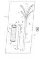
- FIG. 1is an elevation of a first packaged kit, for which a protection is not sought;
- FIG. 2is an elevation of the kit in a first position of the receiving sleeve
- FIG. 3is a cross-section along a median plane of the kit in a second position of the receiving sleeve
- FIG. 4is a view, similar to that of FIG. 2 , of a second treatment kit for which no protection is sought;
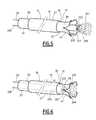
- FIG. 5is an elevation of a third treatment kit for which no protection is sought
- FIG. 6is a view, similar to that of FIG. 2 , of the third treatment kit according to the invention.
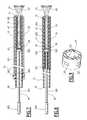
- FIG. 7is a view, similar to that of FIG. 3 , of a first treatment kit according to the invention.
- FIG. 8is a view, similar to that of FIG. 3 , of a second treatment kit according to the invention.
- FIG. 9is a partial perspective view of the sheath of the second kit according to the invention illustrated in FIG. 8 .
- the treatment kit 11 illustrated in FIG. 1which is not covered by the claims of this application, comprises a tubular endoprosthesis 13 , which can be deployed between a retracted state and a deployed state, a sheath 15 for maintaining the endoprosthesis 13 in its retracted state and means 19 for inserting the endoprosthesis 13 into the sheath 15 which comprise a sleeve 17 for receiving the endoprosthesis 13 .
- the endoprosthesis 13comprises a tubular wire-mesh 21 made of a metal which can be implanted, such as stainless steel, which has resilient properties.
- the endoprosthesis 13is self-expanding.
- the endoprosthesis 13can spontaneously deform from its retracted state, in which it has a small diameter, to its deployed state, in which it has a greater diameter, said deployed state being its rest state.
- the wire-mesh 21 of the endoprosthesisis embedded in an expandable film 23 , such as an elastomer, which is impervious to liquids.
- an elastomersuch as a silicone.
- An endoprosthesis of this typeis generally denoted by the term “stent”.
- the elements of the treatment kit 11are packaged in the same packaging 25 formed of, for example, an airtight and watertight pocket.
- the endoprosthesis 13is retained in its deployed state in said packaging 25 .
- the sheath 15is formed of a tube 27 made of plastics material, for example, polytetrafluoroethylene (PTFE), delimiting an inner tube 29 which has a diameter substantially equal to the diameter of a transverse section of the endoprosthesis 13 in its retracted position.
- PTFEpolytetrafluoroethylene
- the sheath 15extends longitudinally between a distal end 31 for insertion into a blood vessel and a proximal end 33 for surgical access.
- the end 31has a divergent conical shape at its tip. However, in a variation, the end 31 is straight.
- the means 19 for introducing the endoprosthesis 13 into the sheath 15are formed from a resilient tube 35 made of polytetrafluoroethylene (PTFE) in which there are arranged a plurality of longitudinal slits from the distal end of said tube 35 .
- PTFEpolytetrafluoroethylene
- the tube 35delimits, in its slitted part, the receiving sleeve 17 and, in its solid part, a cylinder 37 for controlling the movement of the endoprosthesis.
- the receiving sleeve 17 of the endoprosthesis 13comprises a ring 39 for retaining an end of the endoprosthesis 13 and a plurality of flexible guiding prongs 41 .
- the retaining ring 39is formed by the end of the solid part of the tube 35 . It has an outer diameter which is smaller than or substantially equal to the inner diameter of the sheath 15 .
- the flexible prongs 41extend from the retaining ring 39 to the free ends which are not connected.
- the prongs 41are laterally delimited by the slits arranged in the tube 39 .
- the flexible prongs 41are displaceable between a position at a distance from a central axis X-X′ defined by the ring 39 and a position next to said central axis X-X′.
- the length of the flexible prongs 41is at least substantially equal to the length of the endoprosthesis 13 in such a way that when an end of the endoprosthesis 13 is inserted into the ring 39 , the prongs 41 , in their position in the proximity of axis X-X′, extend in a manner substantially following the length of the endoprosthesis 13 .
- the receiving sleeve 17can slide in relation to the sheath 15 between a dilated position for receiving the endoprosthesis 13 outside the sheath 15 , in which the prongs 41 are disposed at a distance from the central axis X-X′, an intermediate position for inserting the ring 39 into the sheath 15 and a compressed interposed position in the sheath 15 between the endoprosthesis 13 and the sheath 15 .
- the retaining ring 39is inserted into the sheath 15 .
- the prongs 41project at least partially outside the sheath 15 and have a shape which diverges substantially towards the outside of the sheath 15 .
- the prongs 41are progressively compressed towards the axis X-X′ by being pressed against the peripheral region at the distal end 31 of the sheath 15 .
- the sleeve 17 containing the endoprosthesis 13is substantially completely inserted inside the sheath 15 .
- the endoprosthesis 13is maintained in its retracted state and the prongs 41 are flattened against the wire-mesh 21 of the endoprosthesis 13 by the internal wall of the sheath 15 .
- the controlling cylinder 37is longer than the sheath 15 in such a way that its proximal end 53 protrudes beyond the proximal end 33 of the sheath 15 when it is disposed in the sheath 15 .
- the controlling cylinder 37can slide inside the sheath 15 when pushed at its proximal end 53 .
- the controlling cylinder 37thus also forms a means for extracting the endoprosthesis 13 from the sheath 15 during its implantation in a blood vessel, as described in more detail below.
- the retaining ring 39 , the flexible prongs 41 , and the controlling cylinder 37are integral. In a variation they are separate parts.
- This methodcomprises a preservation phase and a preparation phase.
- the endoprosthesis 13is retained in the packaging 25 in its deployed state which allows the mechanical or morphological properties of the endoprosthesis 13 to be preserved, in particular when its tubular wire-mesh 21 is imbedded in a film 23 which is expandable and air and water tight.
- the surgeonopens the packaging 25 and cuts the endoprosthesis 13 lengthwise so that it matches the morphology of the blood vessel in which it is to be implanted.
- the surgeonslides the controlling cylinder 37 into the sheath 15 .
- the sleeve 17is disposed in its position for receiving the endoprosthesis 13 , in which the ring 39 and the prongs 41 of the receiving sleeve 17 project outside the sheath 15 .
- the endoprosthesis 13is then held in the ring 39 in a tight-fitting manner at the end of the controlling cylinder 37 .
- the prongs 41face the frame 21 .
- the surgeonthen pulls on the proximal end 53 of the controlling cylinder 37 and moves said end 53 away from the sheath 15 .
- the ring 39 , the prongs 41 and the endoprosthesis 13thus slide into the sheath 15 .
- the prongs 41slide against the internal wall of the sheath 15 and prevent substantially all contact between said internal wall and the frame 21 of the endoprosthesis 13 . Due to the shape of the prongs 41 which diverge towards the exterior of the sheath 15 , the prongs 41 are progressively compressed towards the axis X-X′ by pressure on the peripheral region at the distal end 31 of the sheath 15 . This allows the endoprosthesis 13 to be progressively compressed from its deployed state to its retracted state, as illustrated by FIG. 3 .
- the minimum traction that must be applied to the controlling cylinder 37 in order to insert the endoprosthesis 13 into the sheath 15is thus substantially equal to the friction between the receiving sleeve 17 and the inner wall of the sheath 15 .
- the ratio of the coefficient of friction between the endoprosthesis 13 and the inner wall of the sheath 15 and to the coefficient of friction between the receiving sleeve 17 and the inner wall of the sheath 15is greater than 10 and is, in particular, between 10 and 100.
- the surgeonimplants a surgical guide (not illustrated) into the blood vessel or the vein and this runs from the external insertion point to the region of the vein or the artery where the endoprosthesis 13 is to be implanted.
- the endoprosthesis 13is maintained in its retracted position by the sheath 15 and is then inserted up to the point where it is to be implanted by means of displacement along the surgical guide.
- the surgeondeploys the distal end 63 of the endoprosthesis 13 into the vessel by pushing the controlling cylinder 37 in order to displace its proximal end 53 towards the sheath 15 .
- the distal end 63 of the endoprosthesis 13opens out outside the sheath by spreading open the flexible prongs 41 in such a way that the wire-mesh 21 moves close to the walls of the vessels to be treated and comes to press on said walls.
- the presence of the receiving sleeve 17also substantially eliminates the friction between the endoprosthesis 13 and the sheath 15 which facilitates deployment of the endoprosthesis 13 into the vessel.
- the endoprosthesis 13is mounted coaxially on a sole prop 101 and is fixed on said prop 101 by detachable retaining filaments 103 , 105 of the type described in the French application No. 03 14424.
- the filaments 103 , 105are engaged in the frame 21 respectively at the distal end 63 and proximal end 61 of the endoprosthesis 13 and form at these ends 61 , 63 tightening loops, the length of which can be controlled by extensions of the filaments 103 , 105 up to the proximal end of the prop 101 .
- the diameter of the prop 101is substantially smaller than the inner diameter of the sheath 15 and of the ring 39 .
- the receiving sleeve 17 , the controlling cylinder 37 engaged in the sheath 15 and the endoprosthesis 13 in its deployed stateare coaxially disposed on the prop 101 .
- the surgeonintroduces the proximal end 61 of the endoprosthesis into the ring 39 then simultaneously displaces the proximal ends of the prop 101 and the controlling cylinder 37 away from the proximal end 33 of the sheath 15 .
- the endoprosthesis 13 received in the sleeve 17then penetrates the sheath 15 as previously described.
- the endoprosthesis 13has a cross-section with a minimal diameter along the whole of its length.
- the kitcomprises a heart valve 201 deployable between a retracted state and a deployed state.
- valve 201 in its deployed stateis fixed at its converging end 203 to an introduction tube 205 .
- This fasteningtakes place, for example, with the aid of a retaining filament 207 which can be detached from the external point of insertion into the blood circulation system to be treated.
- the receiving sleeve 17 then the sheath 15are coaxially mounted on the introduction tube 205 in such a way that the proximal end of said tube 205 projects beyond the sheath 15 .
- the surgeonslides the proximal end of the tube 205 at a distance from the proximal end 33 of the sheath 15 into the sheath 15 whilst keeping the receiving sleeve 17 substantially fixed in relation to the sheath 15 with the aid of the controlling cylinder 37 .
- Displacement of the tube 205allows the converging end 203 of the valve 201 to be introduced into the ring 39 .
- the flexible prongs 41face the wire-mesh 209 of the valve 201 and thus have a shape which diverges substantially away from the sheath.
- the surgeonthen displaces the proximal end 53 of the controlling cylinder 37 away from the sheath 15 .
- the valve 201being fixed in the ring 39 , the displacement of the proximal end of the tube 205 at a distance from the sheath 15 continues.
- the assembly formed by the valve 201 and its receiving sleeve 17is then inserted into the sheath 15 .
- Deployment of the valve 201takes place as previously described for the endoprosthesis 13 , the last step consisting of detaching the retaining wire 207 from the valve 201 then removing the tube 205 from the blood circulation system.
- the kitfacilitates extraction of the treatment element 13 , 201 from the sheath 15 during the implantation of said element in a blood circulation system.
- This kitallows the treatment element 13 , 201 to retain its deployed state and, if necessary, to be cut to size just before its implantation so as to match the length of the blood vessel in which it is to be implanted.
- the first kit according to the inventionillustrated in FIG. 7 , differs from the kit illustrated in FIG. 3 with regard to the following characteristics.
- the introduction means 19 (i.e., a pulling unit) of the endoprosthesis 13 into the sheath 15comprise a rod 301 for controlling displacement of the receiving sleeve 17 engaged in the sheath 15 and a pulling collar 302 of the sleeve 17 mounted on the sheath 15 .
- the rod 301is equipped, at its proximal end, with a grip 303 , and at its distal end, with a piston 305 for pushing the endoprosthesis 13 .
- the piston 305is slidingly mounted inside the sheath 15 .
- the retaining ring 39 of the endoprosthesis 13 formed in the receiving sleeve 17is fixed on a distal surface of the piston 305 , opposite the rod 301 .
- Each prong 41 of the sleeve 17comprises a return strand 310 which projects outside the sheath 15 .
- the return strands 310are curved back against the outer surface, denoted as 311 , of the sheath.
- the free ends 309 of the prongs 41are fixed along a distal peripheral surface of the pulling collar 302 .
- the collar 302is slidingly mounted on an outer surface 311 of the sheath 15 . It is mobile along the sheath 15 between a proximal position of deployment of the endoprosthesis 13 into the sheath 15 , in which the collar is at a distance from the detached end of the endoprosthesis, and a distal position which it is in when the endoprosthesis 13 is completely inserted into the sheath 15 and in which the collar is nearer to the releasing end.
- the collar 302further comprises guiding means (not illustrated) which prevent the collar from rotating about the longitudinal axis of the sheath 15 .
- the length of the prongs 41is at least three times greater than the length of the endoprosthesis 13 in such a way that the collar 302 , in its proximal and distal positions, remains outside the patient's body.
- the features of the first kit according to the inventionare similar to the features of the first kit described in FIGS. 1 to 3 .
- the piston 305is disposed in the proximity of the distal end 31 of the sheath.
- the retaining ring 39is thus arranged in the sheath 15 in the proximity of the distal end 31 .
- the collar 302is maintained in its proximal position. The position of the collar 302 is adjusted manually by pulling it towards the proximal end 33 of the sheath 15 so the return strands 310 of the prongs 41 are flattened on the outer surface 311 of the sheath. The maximal transverse dimension of the kit is therefore reduced.
- the proximal end 61 of the endoprosthesis 13is inserted into the retaining ring 39 .
- the piston 305is thus displaced towards the proximal end 33 of the sheath 15 by using the grip 303 .
- the prongs 41 and the endoprosthesis 13penetrate the sheath 15 .
- the prongs 41interpose between the endoprosthesis 13 and the sheath 15 .
- the collar 302is pulled towards its distal position by the guiding prongs 41 .
- the surgeonIn order to deposit the endoprosthesis 13 inside the patient, the surgeon simultaneously moves the grip 303 towards the distal end 31 of the sheath 15 and the collar 302 towards the proximal end 33 of said sheath 15 to pull the return strands 310 of the prongs 41 towards the end 33 .
- the prongs 41are flattened against the outer surface 311 of the sheath 15 , which limits the risk of injuring the patient during deployment of the endoprosthesis, in particular by tearing the wall of the blood vessel.
- the first kit according to the inventionmay include the characteristics of the kit in FIG. 4 or of the kit in FIGS. 5 and 6 with the exception of the flexible prongs 41 which are curved back to the outside of the sheath.
- the second kit according to the inventionillustrated in FIG. 8 , differs from the kit illustrated in FIG. 7 with regard to the following characteristics.
- the sheath 15comprises a plurality of transverse passages 321 arranged in the lateral wall of the sheath. These passages 321 extend substantially along the periphery of a transverse section of the sheath 15 . The distance between the distal end 31 and the passages 321 is greater than the length of the endoprosthesis 13 .
- the number of passages 321is equal to the number of prongs 41 . Furthermore, the width of the passages 321 , taken from along the periphery, is substantially equal to the width of the prongs 41 .
- the free ends 309 of prongs 41are engaged through the passages 321 and are fixed on a proximal surface of the piston 305 .
- the pistonthus forms a means for pulling the return strands 310 .
- the length of the prongs 41is designed to be substantially equal to two times the length which separates the proximal end 31 of the passages 321 .
- the return strands 310 of the prongs 41 arranged outside the sheath 15are therefore flattened on the outer surface 310 of the sheath 15 .
- Each prong 41is curved around a distal region 325 of the sheath 15 delimited by a passage 321 and the distal end 31 .
- Each prong 41forms, around this region, a conveyor band for inserting the endoprosthesis 13 into the sheath 15 .
- the ring 39is placed at the distal end 31 of the sheath 15 by displacement of the piston 305 . Then, the proximal end 61 of the endoprosthesis 13 is inserted into the ring 39 and the piston 305 is displaced towards the distal end 33 of the sheath 15 .
- Deployment of the endoprosthesis 13takes place by displacing said piston 305 towards the proximal end 31 of the sheath 15 .
Landscapes
- Health & Medical Sciences (AREA)
- Engineering & Computer Science (AREA)
- Biomedical Technology (AREA)
- Heart & Thoracic Surgery (AREA)
- Oral & Maxillofacial Surgery (AREA)
- Transplantation (AREA)
- Cardiology (AREA)
- Vascular Medicine (AREA)
- Life Sciences & Earth Sciences (AREA)
- Animal Behavior & Ethology (AREA)
- General Health & Medical Sciences (AREA)
- Public Health (AREA)
- Veterinary Medicine (AREA)
- Prostheses (AREA)
- Media Introduction/Drainage Providing Device (AREA)
Abstract
Description
- at least one implantable treatment element which can be radially deformed between a retracted state and a deployed state;
- a sheath for holding the treatment element in its retracted state;
- means for pulling the treatment element into the sheath;
- the receiving sleeve comprises a region for retaining an end of the treatment element and a region for guiding the treatment element when the retaining region is inside the sheath and the guiding region projects outside the sheath;
- the treatment element is detachably fixed to the introduction means;
- the introduction means form the means for extracting the treatment element from the sheath;
- the receiving sleeve comprises at least two flexible prongs joined together by a common base and having free ends which are not connected;
- the introduction means comprise an element for controlling displacement of the receiving sleeve in relation to the sheath, the controlling element and the receiving sleeve being integral;
- the coefficient of friction between the receiving sleeve and the sheath is less than the coefficient of friction between the treatment element and the sheath;
- the treatment element is an endoprosthesis comprising a deployable frame; and
- the treatment element is a deployable valve;
- the sleeve comprises, in its receiving position, an end for retaining the endoprosthesis, the pulling element being integral with a free end of the sleeve;
- the pulling element comprises a collar slidingly mounted to the outside of the sheath;
- the pulling element is connected in translation to the retaining end;
- the pulling element is disposed in the sheath, the sheath comprising at least one lateral passage in which the free end of the sleeve is engaged; and
- each flexible prong is curved around a distal region of the sheath delimited by a lateral passage and a distal end of the sheath.
Claims (12)
Applications Claiming Priority (3)
| Application Number | Priority Date | Filing Date | Title |
|---|---|---|---|
| FR0505044AFR2885794B1 (en) | 2005-05-19 | 2005-05-19 | NECESSARY FOR LANDING A CAVITY TREATMENT BODY AND METHOD FOR PREPARING A TREATMENT BODY THEREFOR |
| FR0505044 | 2005-05-19 | ||
| PCT/FR2006/001088WO2006123046A1 (en) | 2005-05-19 | 2006-05-15 | Kit for inserting a cavity-treatment element and method of preparing an associated treatment element |
Publications (2)
| Publication Number | Publication Date |
|---|---|
| US20090299449A1 US20090299449A1 (en) | 2009-12-03 |
| US8202309B2true US8202309B2 (en) | 2012-06-19 |
Family
ID=35677380
Family Applications (1)
| Application Number | Title | Priority Date | Filing Date |
|---|---|---|---|
| US11/920,628Expired - Fee RelatedUS8202309B2 (en) | 2005-05-19 | 2006-05-15 | Kit for inserting a cavity-treatment element and method for preparing an associated treatment element |
Country Status (5)
| Country | Link |
|---|---|
| US (1) | US8202309B2 (en) |
| EP (1) | EP1898847B1 (en) |
| CN (1) | CN101247776B (en) |
| FR (1) | FR2885794B1 (en) |
| WO (1) | WO2006123046A1 (en) |
Cited By (21)
| Publication number | Priority date | Publication date | Assignee | Title |
|---|---|---|---|---|
| US9226839B1 (en)* | 2013-03-14 | 2016-01-05 | W. L. Gore & Associates, Inc. | Torque sleeve |
| US9636244B2 (en)* | 2015-04-09 | 2017-05-02 | Mubin I. Syed | Apparatus and method for proximal to distal stent deployment |
| US9949816B2 (en) | 2013-06-14 | 2018-04-24 | Avantec Vascular Corporation | IVC filter retrieval systems with multiple capture modes |
| US9980838B2 (en) | 2015-10-30 | 2018-05-29 | Ram Medical Innovations Llc | Apparatus and method for a bifurcated catheter for use in hostile aortic arches |
| US10173031B2 (en) | 2016-06-20 | 2019-01-08 | Mubin I. Syed | Interchangeable flush/selective catheter |
| US10278804B2 (en) | 2014-12-12 | 2019-05-07 | Avantec Vascular Corporation | IVC filter retrieval systems with releasable capture feature |
| US10314634B2 (en) | 2014-11-04 | 2019-06-11 | Avantec Vascular Corporation | Catheter device with longitudinally expanding interior components for compressing cancellous bone |
| US10327929B2 (en) | 2015-10-30 | 2019-06-25 | Ram Medical Innovations, Llc | Apparatus and method for stabilization of procedural catheter in tortuous vessels |
| US10449335B2 (en) | 2013-05-03 | 2019-10-22 | C.R. Bard, Inc. | Peelable protective sheath |
| US10492936B2 (en) | 2015-10-30 | 2019-12-03 | Ram Medical Innovations, Llc | Apparatus and method for improved access of procedural catheter in tortuous vessels |
| US10569063B2 (en) | 2014-10-03 | 2020-02-25 | W. L. Gore & Associates, Inc. | Removable covers for drug eluting medical devices |
| US10588766B2 (en) | 2012-11-21 | 2020-03-17 | Ram Medical Innovations, Llc | Steerable intravascular anchor and method of operation |
| US10779976B2 (en) | 2015-10-30 | 2020-09-22 | Ram Medical Innovations, Llc | Apparatus and method for stabilization of procedural catheter in tortuous vessels |
| US10856962B2 (en) | 2014-12-12 | 2020-12-08 | Avantec Vascular Corporation | IVC filter retrieval systems with interposed support members |
| US10857014B2 (en) | 2018-02-18 | 2020-12-08 | Ram Medical Innovations, Llc | Modified fixed flat wire bifurcated catheter and its application in lower extremity interventions |
| US10874499B2 (en) | 2016-12-22 | 2020-12-29 | Avantec Vascular Corporation | Systems, devices, and methods for retrieval systems having a tether |
| US11020256B2 (en) | 2015-10-30 | 2021-06-01 | Ram Medical Innovations, Inc. | Bifurcated “Y” anchor support for coronary interventions |
| US11389627B1 (en) | 2018-10-02 | 2022-07-19 | Lutonix Inc. | Balloon protectors, balloon-catheter assemblies, and methods thereof |
| EP3329882B1 (en)* | 2006-10-22 | 2023-09-20 | IDEV Technologies, INC. | Methods for securing strand ends and the resulting devices |
| US11833025B2 (en) | 2018-06-29 | 2023-12-05 | Avantec Vascular Corporation | Systems and methods for implants and deployment devices |
| US12121460B2 (en) | 2010-05-27 | 2024-10-22 | Idev Technologies, Inc. | Stent delivery system with pusher assembly |
Families Citing this family (75)
| Publication number | Priority date | Publication date | Assignee | Title |
|---|---|---|---|---|
| US7018401B1 (en) | 1999-02-01 | 2006-03-28 | Board Of Regents, The University Of Texas System | Woven intravascular devices and methods for making the same and apparatus for delivery of the same |
| US6866679B2 (en) | 2002-03-12 | 2005-03-15 | Ev3 Inc. | Everting stent and stent delivery system |
| KR101659197B1 (en) | 2006-10-22 | 2016-09-22 | 이데브 테크놀로지스, 아이엔씨. | Devices and methods for stent advancement |
| WO2011031587A1 (en) | 2009-09-10 | 2011-03-17 | Boston Scientific Scimed, Inc. | Endoprosthesis with filament repositioning or retrieval member and guard structure |
| US8870950B2 (en) | 2009-12-08 | 2014-10-28 | Mitral Tech Ltd. | Rotation-based anchoring of an implant |
| US20110224785A1 (en) | 2010-03-10 | 2011-09-15 | Hacohen Gil | Prosthetic mitral valve with tissue anchors |
| US8465541B2 (en)* | 2010-04-19 | 2013-06-18 | Medtronic, Inc. | Transcatheter prosthetic heart valve delivery system and method with expandable stability tube |
| US10751206B2 (en) | 2010-06-26 | 2020-08-25 | Scott M. Epstein | Catheter or stent delivery system |
| US20110319902A1 (en)* | 2010-06-26 | 2011-12-29 | Scott Epstein | Catheter delivery system |
| US9763657B2 (en) | 2010-07-21 | 2017-09-19 | Mitraltech Ltd. | Techniques for percutaneous mitral valve replacement and sealing |
| US11653910B2 (en) | 2010-07-21 | 2023-05-23 | Cardiovalve Ltd. | Helical anchor implantation |
| US9675487B2 (en) | 2010-11-17 | 2017-06-13 | Cook Medical Technologies Llc | Prosthesis deployment system for vascular repair |
| US20140324164A1 (en) | 2011-08-05 | 2014-10-30 | Mitraltech Ltd. | Techniques for percutaneous mitral valve replacement and sealing |
| EP2739214B1 (en) | 2011-08-05 | 2018-10-10 | Cardiovalve Ltd | Percutaneous mitral valve replacement and sealing |
| WO2013021374A2 (en) | 2011-08-05 | 2013-02-14 | Mitraltech Ltd. | Techniques for percutaneous mitral valve replacement and sealing |
| US8852272B2 (en) | 2011-08-05 | 2014-10-07 | Mitraltech Ltd. | Techniques for percutaneous mitral valve replacement and sealing |
| US10213329B2 (en) | 2011-08-12 | 2019-02-26 | W. L. Gore & Associates, Inc. | Evertable sheath devices, systems, and methods |
| WO2013028605A1 (en) | 2011-08-22 | 2013-02-28 | Cook Medical Technologies Llc | Emergency vessel repair prosthesis deployment system |
| US9782282B2 (en) | 2011-11-14 | 2017-10-10 | W. L. Gore & Associates, Inc. | External steerable fiber for use in endoluminal deployment of expandable devices |
| US9877858B2 (en) | 2011-11-14 | 2018-01-30 | W. L. Gore & Associates, Inc. | External steerable fiber for use in endoluminal deployment of expandable devices |
| US9072624B2 (en) | 2012-02-23 | 2015-07-07 | Covidien Lp | Luminal stenting |
| US20130226278A1 (en) | 2012-02-23 | 2013-08-29 | Tyco Healthcare Group Lp | Methods and apparatus for luminal stenting |
| US9375308B2 (en) | 2012-03-13 | 2016-06-28 | W. L. Gore & Associates, Inc. | External steerable fiber for use in endoluminal deployment of expandable devices |
| US9078659B2 (en) | 2012-04-23 | 2015-07-14 | Covidien Lp | Delivery system with hooks for resheathability |
| US9724222B2 (en)* | 2012-07-20 | 2017-08-08 | Covidien Lp | Resheathable stent delivery system |
| FR2997288B1 (en)* | 2012-10-25 | 2015-01-23 | Cormove | DEVICE FOR PLACING A SEAL AROUND AN IMPLANT IN A BLOOD CIRCULATION PASSAGE, AND TREATMENT NECESSARY THEREFOR |
| US8628571B1 (en) | 2012-11-13 | 2014-01-14 | Mitraltech Ltd. | Percutaneously-deliverable mechanical valve |
| US9907641B2 (en) | 2014-01-10 | 2018-03-06 | W. L. Gore & Associates, Inc. | Implantable intraluminal device |
| US20150351906A1 (en) | 2013-01-24 | 2015-12-10 | Mitraltech Ltd. | Ventricularly-anchored prosthetic valves |
| US9763819B1 (en) | 2013-03-05 | 2017-09-19 | W. L. Gore & Associates, Inc. | Tapered sleeve |
| US9987155B1 (en)* | 2013-03-07 | 2018-06-05 | W. L. Gore & Associates, Inc. | Implantable medical devices and related delivery systems |
| US10130500B2 (en) | 2013-07-25 | 2018-11-20 | Covidien Lp | Methods and apparatus for luminal stenting |
| US9782186B2 (en) | 2013-08-27 | 2017-10-10 | Covidien Lp | Vascular intervention system |
| US10045867B2 (en) | 2013-08-27 | 2018-08-14 | Covidien Lp | Delivery of medical devices |
| WO2015077229A1 (en)* | 2013-11-19 | 2015-05-28 | W.L. Gore & Associates, Inc. | External steerable fiber for use in endoluminal deployment of expandable devices |
| US10966850B2 (en) | 2014-03-06 | 2021-04-06 | W. L. Gore & Associates, Inc. | Implantable medical device constraint and deployment apparatus |
| US9364361B2 (en)* | 2014-03-13 | 2016-06-14 | Abbott Cardiovascular Systems Inc. | Striped sheaths for medical devices |
| FR3020265B1 (en) | 2014-04-24 | 2019-09-06 | Cormove | DEVICE FOR PLACING A SEAL AROUND AN IMPLANT IN A BLOOD CIRCULATION PASSAGE, AND TREATMENT NECESSARY THEREFOR |
| FR3023703B1 (en)* | 2014-07-17 | 2021-01-29 | Cormove | BLOOD CIRCULATION DUCT TREATMENT DEVICE |
| EP3174502B1 (en) | 2014-07-30 | 2022-04-06 | Cardiovalve Ltd | Apparatus for implantation of an articulatable prosthetic valve |
| EP3229742A1 (en)* | 2014-12-09 | 2017-10-18 | Cook Medical Technologies LLC | Two pronged handle |
| US9974651B2 (en) | 2015-02-05 | 2018-05-22 | Mitral Tech Ltd. | Prosthetic valve with axially-sliding frames |
| CN110141399B (en) | 2015-02-05 | 2021-07-27 | 卡迪尔维尔福股份有限公司 | Prosthetic valve with axial sliding frame |
| JP6589337B2 (en)* | 2015-03-31 | 2019-10-16 | 日本ゼオン株式会社 | Stent delivery device |
| EP3313330A4 (en)* | 2015-06-29 | 2019-03-20 | 480 Biomedical, Inc. | SUPPORT LOADING AND DISTRIBUTION SYSTEMS |
| CN105640620A (en)* | 2015-12-31 | 2016-06-08 | 先健科技(深圳)有限公司 | Interventional medical instrument, conveying device and interventional medical system |
| US10531866B2 (en) | 2016-02-16 | 2020-01-14 | Cardiovalve Ltd. | Techniques for providing a replacement valve and transseptal communication |
| US20190231525A1 (en) | 2016-08-01 | 2019-08-01 | Mitraltech Ltd. | Minimally-invasive delivery systems |
| CA3031187A1 (en) | 2016-08-10 | 2018-02-15 | Cardiovalve Ltd. | Prosthetic valve with concentric frames |
| USD800908S1 (en) | 2016-08-10 | 2017-10-24 | Mitraltech Ltd. | Prosthetic valve element |
| JP6564757B2 (en)* | 2016-11-11 | 2019-08-21 | 日本ライフライン株式会社 | Treatment device |
| US10376396B2 (en) | 2017-01-19 | 2019-08-13 | Covidien Lp | Coupling units for medical device delivery systems |
| CA3055567C (en) | 2017-03-08 | 2021-11-23 | W. L. Gore & Associates, Inc. | Steering wire attach for angulation |
| US11793633B2 (en) | 2017-08-03 | 2023-10-24 | Cardiovalve Ltd. | Prosthetic heart valve |
| US11246704B2 (en) | 2017-08-03 | 2022-02-15 | Cardiovalve Ltd. | Prosthetic heart valve |
| US10537426B2 (en) | 2017-08-03 | 2020-01-21 | Cardiovalve Ltd. | Prosthetic heart valve |
| US12064347B2 (en) | 2017-08-03 | 2024-08-20 | Cardiovalve Ltd. | Prosthetic heart valve |
| US10888421B2 (en) | 2017-09-19 | 2021-01-12 | Cardiovalve Ltd. | Prosthetic heart valve with pouch |
| US10575948B2 (en) | 2017-08-03 | 2020-03-03 | Cardiovalve Ltd. | Prosthetic heart valve |
| EP3694450B1 (en) | 2017-10-11 | 2023-08-02 | W. L. Gore & Associates, Inc. | Implantable medical device constraint and deployment apparatus |
| GB201720803D0 (en) | 2017-12-13 | 2018-01-24 | Mitraltech Ltd | Prosthetic Valve and delivery tool therefor |
| GB201800399D0 (en) | 2018-01-10 | 2018-02-21 | Mitraltech Ltd | Temperature-control during crimping of an implant |
| US10786377B2 (en) | 2018-04-12 | 2020-09-29 | Covidien Lp | Medical device delivery |
| US11071637B2 (en) | 2018-04-12 | 2021-07-27 | Covidien Lp | Medical device delivery |
| US11413176B2 (en) | 2018-04-12 | 2022-08-16 | Covidien Lp | Medical device delivery |
| US11123209B2 (en) | 2018-04-12 | 2021-09-21 | Covidien Lp | Medical device delivery |
| AU2018439076B2 (en) | 2018-08-31 | 2022-07-07 | W. L. Gore & Associates, Inc. | Apparatus, system, and method for steering an implantable medical device |
| CN109833136A (en)* | 2019-02-05 | 2019-06-04 | 尹振图 | Menstrual cup applicator |
| US11413174B2 (en) | 2019-06-26 | 2022-08-16 | Covidien Lp | Core assembly for medical device delivery systems |
| US11504254B2 (en)* | 2020-03-05 | 2022-11-22 | Fluid Biomed Inc. | System and methods for compressing endovascular devices |
| US20220142771A1 (en)* | 2020-11-09 | 2022-05-12 | Medtronic, Inc. | Mechanical guides for controlling leaflet folding behavior during crimping |
| US12357459B2 (en) | 2020-12-03 | 2025-07-15 | Cardiovalve Ltd. | Transluminal delivery system |
| US12042413B2 (en) | 2021-04-07 | 2024-07-23 | Covidien Lp | Delivery of medical devices |
| US12109137B2 (en) | 2021-07-30 | 2024-10-08 | Covidien Lp | Medical device delivery |
| US11944558B2 (en) | 2021-08-05 | 2024-04-02 | Covidien Lp | Medical device delivery devices, systems, and methods |
Citations (13)
| Publication number | Priority date | Publication date | Assignee | Title |
|---|---|---|---|---|
| US4271839A (en)* | 1979-07-25 | 1981-06-09 | Thomas J. Fogarty | Dilation catheter method and apparatus |
| US4863440A (en)* | 1985-12-23 | 1989-09-05 | Thomas J. Fogarty | Pressurized manual advancement dilatation catheter |
| EP0472731A1 (en) | 1990-02-15 | 1992-03-04 | Kanji Inoue | Resilient and bendable instrument inserted into human organ |
| US5364345A (en)* | 1991-10-18 | 1994-11-15 | Imagyn Medical, Inc. | Method of tubal recanalization and catheter system therefor |
| WO1996032078A1 (en) | 1995-04-14 | 1996-10-17 | Schneider (Usa) Inc. | Rolling membrane stent delivery device |
| US6059813A (en) | 1998-11-06 | 2000-05-09 | Scimed Life Systems, Inc. | Rolling membrane stent delivery system |
| US6395014B1 (en)* | 1997-09-26 | 2002-05-28 | John A. Macoviak | Cerebral embolic protection assembly and associated methods |
| US20020077691A1 (en) | 2000-12-18 | 2002-06-20 | Advanced Cardiovascular Systems, Inc. | Ostial stent and method for deploying same |
| US20070016247A1 (en)* | 2001-12-13 | 2007-01-18 | Scimed Life Systems, Inc. | Hydraulic controlled retractable tip filter retrieval catheter |
| US7285130B2 (en)* | 2004-04-27 | 2007-10-23 | Boston Scientific Scimed, Inc. | Stent delivery system |
| US20080027528A1 (en)* | 2006-07-31 | 2008-01-31 | Boston Scientific Scimed, Inc. | Stent retaining mechanisms |
| US7393358B2 (en)* | 2004-08-17 | 2008-07-01 | Boston Scientific Scimed, Inc. | Stent delivery system |
| US7955370B2 (en)* | 2004-08-06 | 2011-06-07 | Boston Scientific Scimed, Inc. | Stent delivery system |
Family Cites Families (4)
| Publication number | Priority date | Publication date | Assignee | Title |
|---|---|---|---|---|
| US5683451A (en)* | 1994-06-08 | 1997-11-04 | Cardiovascular Concepts, Inc. | Apparatus and methods for deployment release of intraluminal prostheses |
| US6053813A (en)* | 1997-10-14 | 2000-04-25 | Mathis; Richard M. | Electronic gaming apparatus and method |
| IE980241A1 (en)* | 1998-04-02 | 1999-10-20 | Salviac Ltd | Delivery catheter with split sheath |
| US6830575B2 (en)* | 2002-05-08 | 2004-12-14 | Scimed Life Systems, Inc. | Method and device for providing full protection to a stent |
- 2005
- 2005-05-19FRFR0505044Apatent/FR2885794B1/ennot_activeExpired - Fee Related
- 2006
- 2006-05-15EPEP06764627.3Apatent/EP1898847B1/ennot_activeCeased
- 2006-05-15WOPCT/FR2006/001088patent/WO2006123046A1/enactiveApplication Filing
- 2006-05-15USUS11/920,628patent/US8202309B2/ennot_activeExpired - Fee Related
- 2006-05-15CNCN2006800171282Apatent/CN101247776B/ennot_activeExpired - Fee Related
Patent Citations (17)
| Publication number | Priority date | Publication date | Assignee | Title |
|---|---|---|---|---|
| US4271839A (en)* | 1979-07-25 | 1981-06-09 | Thomas J. Fogarty | Dilation catheter method and apparatus |
| US4863440A (en)* | 1985-12-23 | 1989-09-05 | Thomas J. Fogarty | Pressurized manual advancement dilatation catheter |
| EP0472731A1 (en) | 1990-02-15 | 1992-03-04 | Kanji Inoue | Resilient and bendable instrument inserted into human organ |
| US5364345A (en)* | 1991-10-18 | 1994-11-15 | Imagyn Medical, Inc. | Method of tubal recanalization and catheter system therefor |
| WO1996032078A1 (en) | 1995-04-14 | 1996-10-17 | Schneider (Usa) Inc. | Rolling membrane stent delivery device |
| US5662703A (en) | 1995-04-14 | 1997-09-02 | Schneider (Usa) Inc. | Rolling membrane stent delivery device |
| US6395014B1 (en)* | 1997-09-26 | 2002-05-28 | John A. Macoviak | Cerebral embolic protection assembly and associated methods |
| US6238410B1 (en) | 1998-11-06 | 2001-05-29 | Scimed Life Systems, Inc. | Pulling membrane stent delivery system |
| WO2000027309A1 (en) | 1998-11-06 | 2000-05-18 | Scimed Life Systems, Inc. | Improved rolling membrane stent delivery system |
| US6059813A (en) | 1998-11-06 | 2000-05-09 | Scimed Life Systems, Inc. | Rolling membrane stent delivery system |
| US20020077691A1 (en) | 2000-12-18 | 2002-06-20 | Advanced Cardiovascular Systems, Inc. | Ostial stent and method for deploying same |
| WO2002049538A2 (en) | 2000-12-18 | 2002-06-27 | Advanced Cardiovascular Systems, Inc. | Ostial stent and method for deploying same |
| US20070016247A1 (en)* | 2001-12-13 | 2007-01-18 | Scimed Life Systems, Inc. | Hydraulic controlled retractable tip filter retrieval catheter |
| US7285130B2 (en)* | 2004-04-27 | 2007-10-23 | Boston Scientific Scimed, Inc. | Stent delivery system |
| US7955370B2 (en)* | 2004-08-06 | 2011-06-07 | Boston Scientific Scimed, Inc. | Stent delivery system |
| US7393358B2 (en)* | 2004-08-17 | 2008-07-01 | Boston Scientific Scimed, Inc. | Stent delivery system |
| US20080027528A1 (en)* | 2006-07-31 | 2008-01-31 | Boston Scientific Scimed, Inc. | Stent retaining mechanisms |
Non-Patent Citations (1)
| Title |
|---|
| International Search Report issued Oct. 4, 2006 in the International (PCT) Application of which the present application is the U.S. National Stage. |
Cited By (39)
| Publication number | Priority date | Publication date | Assignee | Title |
|---|---|---|---|---|
| EP3329882B1 (en)* | 2006-10-22 | 2023-09-20 | IDEV Technologies, INC. | Methods for securing strand ends and the resulting devices |
| US12121460B2 (en) | 2010-05-27 | 2024-10-22 | Idev Technologies, Inc. | Stent delivery system with pusher assembly |
| US10588766B2 (en) | 2012-11-21 | 2020-03-17 | Ram Medical Innovations, Llc | Steerable intravascular anchor and method of operation |
| US10639179B2 (en) | 2012-11-21 | 2020-05-05 | Ram Medical Innovations, Llc | System for the intravascular placement of a medical device |
| US9226839B1 (en)* | 2013-03-14 | 2016-01-05 | W. L. Gore & Associates, Inc. | Torque sleeve |
| US10449335B2 (en) | 2013-05-03 | 2019-10-22 | C.R. Bard, Inc. | Peelable protective sheath |
| US9949816B2 (en) | 2013-06-14 | 2018-04-24 | Avantec Vascular Corporation | IVC filter retrieval systems with multiple capture modes |
| US10022213B2 (en) | 2013-06-14 | 2018-07-17 | Avantec Vascular Corporation | Shaping improvements for Inferior Vena Cava filter and retrieval systems |
| US11219517B2 (en) | 2013-06-14 | 2022-01-11 | Avantec Vascular Corporation | Inferior Vena Cava filter and retrieval systems |
| US11051926B2 (en) | 2013-06-14 | 2021-07-06 | Avantec Vascular Corporation | Method for retrieval of a medical device |
| US11013589B2 (en) | 2013-06-14 | 2021-05-25 | Avantec Vascular Corporation | Method for IVC filter retrieval with multiple capture modes |
| US11679240B2 (en) | 2014-10-03 | 2023-06-20 | W. L. Gore & Associates, Inc. | Removable covers for drug eluting medical devices |
| US10569063B2 (en) | 2014-10-03 | 2020-02-25 | W. L. Gore & Associates, Inc. | Removable covers for drug eluting medical devices |
| US10314634B2 (en) | 2014-11-04 | 2019-06-11 | Avantec Vascular Corporation | Catheter device with longitudinally expanding interior components for compressing cancellous bone |
| US10278804B2 (en) | 2014-12-12 | 2019-05-07 | Avantec Vascular Corporation | IVC filter retrieval systems with releasable capture feature |
| US11903810B2 (en) | 2014-12-12 | 2024-02-20 | Avantec Vascular Corporation | Instrument for delivery or capture of a medical device in a blood vessel |
| US10856962B2 (en) | 2014-12-12 | 2020-12-08 | Avantec Vascular Corporation | IVC filter retrieval systems with interposed support members |
| US12318277B2 (en) | 2014-12-12 | 2025-06-03 | Avantec Vascular Corporation | Apparatus and methods for retrieving a foreign body from a vasculature |
| US10478325B2 (en) | 2015-04-09 | 2019-11-19 | Mubin I. Syed | Apparatus and method for proximal to distal stent deployment |
| US9636244B2 (en)* | 2015-04-09 | 2017-05-02 | Mubin I. Syed | Apparatus and method for proximal to distal stent deployment |
| US10888445B2 (en) | 2015-10-30 | 2021-01-12 | Ram Medical Innovations, Inc. | Apparatus and method for stabilization of procedural catheter in tortuous vessels |
| US10327929B2 (en) | 2015-10-30 | 2019-06-25 | Ram Medical Innovations, Llc | Apparatus and method for stabilization of procedural catheter in tortuous vessels |
| US11020256B2 (en) | 2015-10-30 | 2021-06-01 | Ram Medical Innovations, Inc. | Bifurcated “Y” anchor support for coronary interventions |
| US10492936B2 (en) | 2015-10-30 | 2019-12-03 | Ram Medical Innovations, Llc | Apparatus and method for improved access of procedural catheter in tortuous vessels |
| US10779976B2 (en) | 2015-10-30 | 2020-09-22 | Ram Medical Innovations, Llc | Apparatus and method for stabilization of procedural catheter in tortuous vessels |
| US11337837B2 (en) | 2015-10-30 | 2022-05-24 | Ram Medical Innovations, Inc. | Apparatus and method for improved access of procedural catheter in tortuous vessels |
| US9980838B2 (en) | 2015-10-30 | 2018-05-29 | Ram Medical Innovations Llc | Apparatus and method for a bifurcated catheter for use in hostile aortic arches |
| US12121674B2 (en) | 2016-06-20 | 2024-10-22 | Mubin I. Syed | Interchangeable flush/selective catheter |
| US10173031B2 (en) | 2016-06-20 | 2019-01-08 | Mubin I. Syed | Interchangeable flush/selective catheter |
| US11724063B2 (en) | 2016-06-20 | 2023-08-15 | Mubin I. Syed | Interchangeable flush/selective catheter |
| US10874499B2 (en) | 2016-12-22 | 2020-12-29 | Avantec Vascular Corporation | Systems, devices, and methods for retrieval systems having a tether |
| US11833024B2 (en) | 2016-12-22 | 2023-12-05 | Avantec Vascular Corporation | Systems, devices, and methods for retrieval systems having a tether |
| US11877940B2 (en) | 2018-02-18 | 2024-01-23 | Ram Medical Innovations, Inc. | Modified fixed flat wire bifurcated catheter and its application in lower extremity interventions |
| US12011379B2 (en) | 2018-02-18 | 2024-06-18 | Ram Medical Innovations, Inc. | Vascular access devices and methods for lower limb interventions |
| US11007075B2 (en) | 2018-02-18 | 2021-05-18 | Ram Medical Innovations, Inc. | Vascular access devices and methods for lower limb interventions |
| US12201541B2 (en) | 2018-02-18 | 2025-01-21 | Ram Medical Innovations, Inc. | Vascular access devices and methods for lower limb interventions |
| US10857014B2 (en) | 2018-02-18 | 2020-12-08 | Ram Medical Innovations, Llc | Modified fixed flat wire bifurcated catheter and its application in lower extremity interventions |
| US11833025B2 (en) | 2018-06-29 | 2023-12-05 | Avantec Vascular Corporation | Systems and methods for implants and deployment devices |
| US11389627B1 (en) | 2018-10-02 | 2022-07-19 | Lutonix Inc. | Balloon protectors, balloon-catheter assemblies, and methods thereof |
Also Published As
| Publication number | Publication date |
|---|---|
| FR2885794A1 (en) | 2006-11-24 |
| EP1898847A1 (en) | 2008-03-19 |
| FR2885794B1 (en) | 2007-08-17 |
| EP1898847B1 (en) | 2013-07-03 |
| WO2006123046A1 (en) | 2006-11-23 |
| CN101247776A (en) | 2008-08-20 |
| CN101247776B (en) | 2010-09-01 |
| US20090299449A1 (en) | 2009-12-03 |
Similar Documents
| Publication | Publication Date | Title |
|---|---|---|
| US8202309B2 (en) | Kit for inserting a cavity-treatment element and method for preparing an associated treatment element | |
| US8109986B2 (en) | Device for inserting a radially expandable implant, treatment kit and associated insertion method | |
| US8252037B2 (en) | Device for treating a duct through which blood flows and associated preparation method | |
| US9427317B2 (en) | Device for treating a blood circulation canal and process for preparing this device | |
| AU2009255608B2 (en) | Introducer | |
| US8845709B2 (en) | Device for treating a blood vessel | |
| EP2204141B1 (en) | Prosthesis deployment system retention device | |
| US20160015543A1 (en) | Treatment device for a blood circulation conduit | |
| AU2003248771B2 (en) | Thoracic stent-graft introducer | |
| US7927363B2 (en) | Device for treating a blood vessel and associated treatment kit | |
| AU2004228046B2 (en) | Branch stent graft deployment and method | |
| US10058423B2 (en) | Device for placing a seal around an implant in a blood vessel, and associated treatment kit | |
| US8357190B2 (en) | Laparoscopic vascular access | |
| KR20190055135A (en) | Heart ring constriction and ring on heart valve ring | |
| US20070078504A1 (en) | Device for placing a vascular implant | |
| EP2661244B1 (en) | Proximal release expandable prosthesis delivery system | |
| JPH11500034A (en) | Endovascular stent / graft deployment system | |
| CN102548486A (en) | Introducer for prosthetic heart valve | |
| CA2505418A1 (en) | Device and method for treating thoracic aorta | |
| US12108945B2 (en) | Self-expanding hemostatic devices and methods for fascia and vessel passages | |
| US20140031923A1 (en) | Trans-Aortic Surgical Syringe-Type Device for Deployment of a Prosthetic Valve | |
| JP2024511626A (en) | Apparatus and method for implant treatment of arteriovenous grafts | |
| US20020151952A1 (en) | Necessaries for treating a blood vessel | |
| US20130289338A1 (en) | Vehicle tray |
Legal Events
| Date | Code | Title | Description |
|---|---|---|---|
| AS | Assignment | Owner name:LABORATOIRES PEROUSE, FRANCE Free format text:ASSIGNMENT OF ASSIGNORS INTEREST;ASSIGNOR:STYRC, MIKOLAJ WITOLD;REEL/FRAME:020670/0473 Effective date:20071210 | |
| STCF | Information on status: patent grant | Free format text:PATENTED CASE | |
| FPAY | Fee payment | Year of fee payment:4 | |
| AS | Assignment | Owner name:CORMOVE, FRANCE Free format text:ASSIGNMENT OF ASSIGNORS INTEREST;ASSIGNOR:PEROUSE MEDICAL;REEL/FRAME:037195/0801 Effective date:20150628 Owner name:PEROUSE MEDICAL, FRANCE Free format text:MERGER;ASSIGNOR:LABORATOIRES PEROUSE;REEL/FRAME:037196/0238 Effective date:20090101 | |
| MAFP | Maintenance fee payment | Free format text:PAYMENT OF MAINTENANCE FEE, 8TH YR, SMALL ENTITY (ORIGINAL EVENT CODE: M2552); ENTITY STATUS OF PATENT OWNER: SMALL ENTITY Year of fee payment:8 | |
| FEPP | Fee payment procedure | Free format text:MAINTENANCE FEE REMINDER MAILED (ORIGINAL EVENT CODE: REM.); ENTITY STATUS OF PATENT OWNER: SMALL ENTITY | |
| LAPS | Lapse for failure to pay maintenance fees | Free format text:PATENT EXPIRED FOR FAILURE TO PAY MAINTENANCE FEES (ORIGINAL EVENT CODE: EXP.); ENTITY STATUS OF PATENT OWNER: SMALL ENTITY | |
| STCH | Information on status: patent discontinuation | Free format text:PATENT EXPIRED DUE TO NONPAYMENT OF MAINTENANCE FEES UNDER 37 CFR 1.362 | |
| FP | Lapsed due to failure to pay maintenance fee | Effective date:20240619 |