US8202248B2 - Dialysis implant and methods of use - Google Patents
Dialysis implant and methods of useDownload PDFInfo
- Publication number
- US8202248B2 US8202248B2US10/922,478US92247804AUS8202248B2US 8202248 B2US8202248 B2US 8202248B2US 92247804 AUS92247804 AUS 92247804AUS 8202248 B2US8202248 B2US 8202248B2
- Authority
- US
- United States
- Prior art keywords
- reservoir
- pump
- bladder
- conduit
- peritoneal cavity
- Prior art date
- Legal status (The legal status is an assumption and is not a legal conclusion. Google has not performed a legal analysis and makes no representation as to the accuracy of the status listed.)
- Active, expires
Links
- 238000000502dialysisMethods0.000titleclaimsabstractdescription85
- 238000000034methodMethods0.000titleabstractdescription30
- 239000007943implantSubstances0.000titledescription7
- 210000003200peritoneal cavityAnatomy0.000claimsabstractdescription142
- 239000007787solidSubstances0.000claimsabstractdescription36
- 239000012530fluidSubstances0.000claimsdescription129
- 238000004891communicationMethods0.000claimsdescription55
- 238000007920subcutaneous administrationMethods0.000claimsdescription35
- 229920000642polymerPolymers0.000claimsdescription23
- 239000011148porous materialSubstances0.000claimsdescription22
- 210000004379membraneAnatomy0.000claimsdescription19
- 239000012528membraneSubstances0.000claimsdescription19
- 239000002245particleSubstances0.000claimsdescription14
- 239000011159matrix materialSubstances0.000claimsdescription12
- 230000007246mechanismEffects0.000claimsdescription11
- 239000000203mixtureSubstances0.000claimsdescription11
- 239000003792electrolyteSubstances0.000claimsdescription8
- 239000012491analyteSubstances0.000claimsdescription7
- 238000007789sealingMethods0.000claimsdescription6
- 238000002347injectionMethods0.000claimsdescription5
- 239000007924injectionSubstances0.000claimsdescription5
- 230000001939inductive effectEffects0.000claimsdescription4
- 238000002513implantationMethods0.000claimsdescription3
- 230000008878couplingEffects0.000claims4
- 238000010168coupling processMethods0.000claims4
- 238000005859coupling reactionMethods0.000claims4
- 239000011248coating agentSubstances0.000claims1
- 238000000576coating methodMethods0.000claims1
- 238000010254subcutaneous injectionMethods0.000claims1
- 239000007929subcutaneous injectionSubstances0.000claims1
- 239000002699waste materialSubstances0.000abstractdescription25
- 239000008280bloodSubstances0.000abstractdescription8
- 210000004369bloodAnatomy0.000abstractdescription8
- 208000001647Renal InsufficiencyDiseases0.000abstractdescription2
- 201000006370kidney failureDiseases0.000abstractdescription2
- 238000012546transferMethods0.000description113
- 210000003932urinary bladderAnatomy0.000description69
- 239000000463materialSubstances0.000description37
- 238000001802infusionMethods0.000description27
- 239000007788liquidSubstances0.000description27
- 230000004888barrier functionEffects0.000description26
- -1maltose disaccharideChemical class0.000description25
- 239000000243solutionSubstances0.000description24
- 210000003567ascitic fluidAnatomy0.000description14
- 238000002156mixingMethods0.000description14
- 239000003795chemical substances by applicationSubstances0.000description13
- 108090000623proteins and genesProteins0.000description13
- 229920002635polyurethanePolymers0.000description12
- 239000004814polyurethaneSubstances0.000description12
- 102000004169proteins and genesHuman genes0.000description12
- 229910045601alloyInorganic materials0.000description10
- 239000000956alloySubstances0.000description10
- 229920001343polytetrafluoroethylenePolymers0.000description10
- 239000004810polytetrafluoroethyleneSubstances0.000description10
- 239000004696Poly ether ether ketoneSubstances0.000description9
- 239000000385dialysis solutionSubstances0.000description9
- 229920002530polyetherether ketonePolymers0.000description9
- 239000004812Fluorinated ethylene propyleneSubstances0.000description8
- 229920002301cellulose acetatePolymers0.000description8
- 238000004146energy storageMethods0.000description8
- 229910001000nickel titaniumInorganic materials0.000description8
- 210000000056organAnatomy0.000description8
- 229920009441perflouroethylene propylenePolymers0.000description8
- 229920003229poly(methyl methacrylate)Polymers0.000description8
- 239000004926polymethyl methacrylateSubstances0.000description8
- 229920001296polysiloxanePolymers0.000description8
- 102000008186CollagenHuman genes0.000description7
- 108010035532CollagenProteins0.000description7
- 229920004934Dacron®Polymers0.000description7
- 239000004677NylonSubstances0.000description7
- 239000004743PolypropyleneSubstances0.000description7
- 229920001436collagenPolymers0.000description7
- 229920001778nylonPolymers0.000description7
- 230000003204osmotic effectEffects0.000description7
- 229920002492poly(sulfone)Polymers0.000description7
- 229920002239polyacrylonitrilePolymers0.000description7
- 229920000728polyesterPolymers0.000description7
- 229920001155polypropylenePolymers0.000description7
- 230000001225therapeutic effectEffects0.000description7
- DSUFPYCILZXJFF-UHFFFAOYSA-N4-[[4-[[4-(pentoxycarbonylamino)cyclohexyl]methyl]cyclohexyl]carbamoyloxy]butyl n-[4-[[4-(butoxycarbonylamino)cyclohexyl]methyl]cyclohexyl]carbamateChemical compoundC1CC(NC(=O)OCCCCC)CCC1CC1CCC(NC(=O)OCCCCOC(=O)NC2CCC(CC3CCC(CC3)NC(=O)OCCCC)CC2)CC1DSUFPYCILZXJFF-UHFFFAOYSA-N0.000description6
- 229920002614Polyether block amidePolymers0.000description6
- 239000004695Polyether sulfoneSubstances0.000description6
- 239000004721Polyphenylene oxideSubstances0.000description6
- 125000001931aliphatic groupChemical group0.000description6
- 229920002678cellulosePolymers0.000description6
- 239000001913celluloseSubstances0.000description6
- 229920006018co-polyamidePolymers0.000description6
- 238000001962electrophoresisMethods0.000description6
- 238000001631haemodialysisMethods0.000description6
- 230000000322hemodialysisEffects0.000description6
- 229920000570polyetherPolymers0.000description6
- 229920006393polyether sulfonePolymers0.000description6
- 239000004800polyvinyl chlorideSubstances0.000description6
- 239000000047productSubstances0.000description6
- 239000004627regenerated celluloseSubstances0.000description6
- 238000001228spectrumMethods0.000description6
- 229920001169thermoplasticPolymers0.000description6
- 239000004416thermosoftening plasticSubstances0.000description6
- 239000004020conductorSubstances0.000description5
- 239000003814drugSubstances0.000description5
- 229910052751metalInorganic materials0.000description5
- 239000002184metalSubstances0.000description5
- 238000005086pumpingMethods0.000description5
- 230000002485urinary effectEffects0.000description5
- OWEGMIWEEQEYGQ-UHFFFAOYSA-N100676-05-9Natural productsOC1C(O)C(O)C(CO)OC1OCC1C(O)C(O)C(O)C(OC2C(OC(O)C(O)C2O)CO)O1OWEGMIWEEQEYGQ-UHFFFAOYSA-N0.000description4
- DBTMGCOVALSLOR-UHFFFAOYSA-N32-alpha-galactosyl-3-alpha-galactosyl-galactoseNatural productsOC1C(O)C(O)C(CO)OC1OC1C(O)C(OC2C(C(CO)OC(O)C2O)O)OC(CO)C1ODBTMGCOVALSLOR-UHFFFAOYSA-N0.000description4
- RXVWSYJTUUKTEA-UHFFFAOYSA-ND-maltotrioseNatural productsOC1C(O)C(OC(C(O)CO)C(O)C(O)C=O)OC(CO)C1OC1C(O)C(O)C(O)C(CO)O1RXVWSYJTUUKTEA-UHFFFAOYSA-N0.000description4
- WQZGKKKJIJFFOK-GASJEMHNSA-NGlucoseNatural productsOC[C@H]1OC(O)[C@H](O)[C@@H](O)[C@@H]1OWQZGKKKJIJFFOK-GASJEMHNSA-N0.000description4
- 229920000544Gore-TexPolymers0.000description4
- GUBGYTABKSRVRQ-PICCSMPSSA-NMaltoseNatural productsO[C@@H]1[C@@H](O)[C@H](O)[C@@H](CO)O[C@@H]1O[C@@H]1[C@@H](CO)OC(O)[C@H](O)[C@H]1OGUBGYTABKSRVRQ-PICCSMPSSA-N0.000description4
- 239000004698PolyethyleneSubstances0.000description4
- 229920006362Teflon®Polymers0.000description4
- FTNIPWXXIGNQQF-UHFFFAOYSA-NUNPD130147Natural productsOC1C(O)C(O)C(CO)OC1OC1C(CO)OC(OC2C(OC(OC3C(OC(OC4C(OC(O)C(O)C4O)CO)C(O)C3O)CO)C(O)C2O)CO)C(O)C1OFTNIPWXXIGNQQF-UHFFFAOYSA-N0.000description4
- HZEWFHLRYVTOIW-UHFFFAOYSA-N[Ti].[Ni]Chemical compound[Ti].[Ni]HZEWFHLRYVTOIW-UHFFFAOYSA-N0.000description4
- 230000001133accelerationEffects0.000description4
- 238000004140cleaningMethods0.000description4
- 229940039227diagnostic agentDrugs0.000description4
- 239000000032diagnostic agentSubstances0.000description4
- FJCUPROCOFFUSR-UHFFFAOYSA-Nmalto-pentaoseNatural productsOC1C(O)C(OC(C(O)CO)C(O)C(O)C=O)OC(CO)C1OC1C(O)C(O)C(OC2C(C(O)C(OC3C(C(O)C(O)C(CO)O3)O)C(CO)O2)O)C(CO)O1FJCUPROCOFFUSR-UHFFFAOYSA-N0.000description4
- FJCUPROCOFFUSR-GMMZZHHDSA-NmaltopentaoseChemical compoundO[C@@H]1[C@@H](O)[C@@H](O[C@H]([C@H](O)CO)[C@H](O)[C@@H](O)C=O)O[C@H](CO)[C@H]1O[C@@H]1[C@H](O)[C@@H](O)[C@H](O[C@@H]2[C@@H]([C@@H](O)[C@H](O[C@@H]3[C@@H]([C@@H](O)[C@H](O)[C@@H](CO)O3)O)[C@@H](CO)O2)O)[C@@H](CO)O1FJCUPROCOFFUSR-GMMZZHHDSA-N0.000description4
- FYGDTMLNYKFZSV-UHFFFAOYSA-NmannotrioseNatural productsOC1C(O)C(O)C(CO)OC1OC1C(CO)OC(OC2C(OC(O)C(O)C2O)CO)C(O)C1OFYGDTMLNYKFZSV-UHFFFAOYSA-N0.000description4
- HLXZNVUGXRDIFK-UHFFFAOYSA-Nnickel titaniumChemical compound[Ti].[Ti].[Ti].[Ti].[Ti].[Ti].[Ti].[Ti].[Ti].[Ti].[Ti].[Ni].[Ni].[Ni].[Ni].[Ni].[Ni].[Ni].[Ni].[Ni].[Ni].[Ni].[Ni].[Ni].[Ni]HLXZNVUGXRDIFK-UHFFFAOYSA-N0.000description4
- 239000012466permeateSubstances0.000description4
- 229920000573polyethylenePolymers0.000description4
- 229910000684Cobalt-chromeInorganic materials0.000description3
- 229910001182Mo alloyInorganic materials0.000description3
- ZOKXTWBITQBERF-UHFFFAOYSA-NMolybdenumChemical compound[Mo]ZOKXTWBITQBERF-UHFFFAOYSA-N0.000description3
- 229910000691Re alloyInorganic materials0.000description3
- FAPWRFPIFSIZLT-UHFFFAOYSA-MSodium chlorideChemical compound[Na+].[Cl-]FAPWRFPIFSIZLT-UHFFFAOYSA-M0.000description3
- 239000004098TetracyclineSubstances0.000description3
- 239000003990capacitorSubstances0.000description3
- KRKNYBCHXYNGOX-UHFFFAOYSA-Ncitric acidChemical compoundOC(=O)CC(O)(C(O)=O)CC(O)=OKRKNYBCHXYNGOX-UHFFFAOYSA-N0.000description3
- 239000010952cobalt-chromeSubstances0.000description3
- 229910000701elgiloys (Co-Cr-Ni Alloy)Inorganic materials0.000description3
- 230000007717exclusionEffects0.000description3
- 239000004744fabricSubstances0.000description3
- 239000008103glucoseSubstances0.000description3
- 229910052750molybdenumInorganic materials0.000description3
- 239000011733molybdenumSubstances0.000description3
- 210000003205muscleAnatomy0.000description3
- 239000002357osmotic agentSubstances0.000description3
- 210000004303peritoneumAnatomy0.000description3
- 229920000915polyvinyl chloridePolymers0.000description3
- 230000002285radioactive effectEffects0.000description3
- DECCZIUVGMLHKQ-UHFFFAOYSA-Nrhenium tungstenChemical compound[W].[Re]DECCZIUVGMLHKQ-UHFFFAOYSA-N0.000description3
- 229910001256stainless steel alloyInorganic materials0.000description3
- 229930101283tetracyclineNatural products0.000description3
- 229960002180tetracyclineDrugs0.000description3
- 235000019364tetracyclineNutrition0.000description3
- 150000003522tetracyclinesChemical class0.000description3
- 206010007559Cardiac failure congestiveDiseases0.000description2
- 108010037464Cyclooxygenase 1Proteins0.000description2
- 206010019280Heart failuresDiseases0.000description2
- HEFNNWSXXWATRW-UHFFFAOYSA-NIbuprofenChemical compoundCC(C)CC1=CC=C(C(C)C(O)=O)C=C1HEFNNWSXXWATRW-UHFFFAOYSA-N0.000description2
- TWRXJAOTZQYOKJ-UHFFFAOYSA-LMagnesium chlorideChemical compound[Mg+2].[Cl-].[Cl-]TWRXJAOTZQYOKJ-UHFFFAOYSA-L0.000description2
- 102000002274Matrix MetalloproteinasesHuman genes0.000description2
- 108010000684Matrix MetalloproteinasesProteins0.000description2
- 102000001776Matrix metalloproteinase-9Human genes0.000description2
- 108010015302Matrix metalloproteinase-9Proteins0.000description2
- 102100038277Prostaglandin G/H synthase 1Human genes0.000description2
- 208000002223abdominal aortic aneurysmDiseases0.000description2
- 239000011149active materialSubstances0.000description2
- TZCXTZWJZNENPQ-UHFFFAOYSA-Lbarium sulfateChemical compound[Ba+2].[O-]S([O-])(=O)=OTZCXTZWJZNENPQ-UHFFFAOYSA-L0.000description2
- WQZGKKKJIJFFOK-VFUOTHLCSA-Nbeta-D-glucoseChemical compoundOC[C@H]1O[C@@H](O)[C@H](O)[C@@H](O)[C@@H]1OWQZGKKKJIJFFOK-VFUOTHLCSA-N0.000description2
- UHZZMRAGKVHANO-UHFFFAOYSA-Mchlormequat chlorideChemical compound[Cl-].C[N+](C)(C)CCClUHZZMRAGKVHANO-UHFFFAOYSA-M0.000description2
- 238000010276constructionMethods0.000description2
- DDRJAANPRJIHGJ-UHFFFAOYSA-NcreatinineChemical compoundCN1CC(=O)NC1=NDDRJAANPRJIHGJ-UHFFFAOYSA-N0.000description2
- 210000003717douglas' pouchAnatomy0.000description2
- 229940079593drugDrugs0.000description2
- HQQADJVZYDDRJT-UHFFFAOYSA-Nethene;prop-1-eneChemical groupC=C.CC=CHQQADJVZYDDRJT-UHFFFAOYSA-N0.000description2
- 230000006870functionEffects0.000description2
- CGIGDMFJXJATDK-UHFFFAOYSA-NindomethacinChemical compoundCC1=C(CC(O)=O)C2=CC(OC)=CC=C2N1C(=O)C1=CC=C(Cl)C=C1CGIGDMFJXJATDK-UHFFFAOYSA-N0.000description2
- 230000006698inductionEffects0.000description2
- 230000004941influxEffects0.000description2
- 239000003112inhibitorSubstances0.000description2
- 230000003993interactionEffects0.000description2
- 210000003734kidneyAnatomy0.000description2
- 150000002739metalsChemical class0.000description2
- 230000027939micturitionEffects0.000description2
- 210000005036nerveAnatomy0.000description2
- 239000000041non-steroidal anti-inflammatory agentSubstances0.000description2
- QFJCIRLUMZQUOT-HPLJOQBZSA-NsirolimusChemical compoundC1C[C@@H](O)[C@H](OC)C[C@@H]1C[C@@H](C)[C@H]1OC(=O)[C@@H]2CCCCN2C(=O)C(=O)[C@](O)(O2)[C@H](C)CC[C@H]2C[C@H](OC)/C(C)=C/C=C/C=C/[C@@H](C)C[C@@H](C)C(=O)[C@H](OC)[C@H](O)/C(C)=C/[C@@H](C)C(=O)C1QFJCIRLUMZQUOT-HPLJOQBZSA-N0.000description2
- 239000002904solventSubstances0.000description2
- 229910001220stainless steelInorganic materials0.000description2
- 239000010935stainless steelSubstances0.000description2
- 238000001356surgical procedureMethods0.000description2
- 229940124597therapeutic agentDrugs0.000description2
- FYGDTMLNYKFZSV-BYLHFPJWSA-Nβ-1,4-galactotriosideChemical compoundO[C@@H]1[C@@H](O)[C@H](O)[C@@H](CO)O[C@H]1O[C@@H]1[C@H](CO)O[C@@H](O[C@@H]2[C@@H](O[C@@H](O)[C@H](O)[C@H]2O)CO)[C@H](O)[C@H]1OFYGDTMLNYKFZSV-BYLHFPJWSA-N0.000description2
- UKVFUEBRZQZUSZ-BRPMRXRMSA-N(8r,9s,10s,13r,14s,17r)-10,13-dimethyl-17-[(2r)-pent-4-en-2-yl]-2,3,4,5,6,7,8,9,11,12,14,15,16,17-tetradecahydro-1h-cyclopenta[a]phenanthreneChemical compoundC1CC2CCCC[C@]2(C)[C@@H]2[C@@H]1[C@@H]1CC[C@H]([C@@H](CC=C)C)[C@@]1(C)CC2UKVFUEBRZQZUSZ-BRPMRXRMSA-N0.000description1
- CYDQOEWLBCCFJZ-UHFFFAOYSA-N4-(4-fluorophenyl)oxane-4-carboxylic acidChemical compoundC=1C=C(F)C=CC=1C1(C(=O)O)CCOCC1CYDQOEWLBCCFJZ-UHFFFAOYSA-N0.000description1
- BSYNRYMUTXBXSQ-FOQJRBATSA-N59096-14-9Chemical compoundCC(=O)OC1=CC=CC=C1[14C](O)=OBSYNRYMUTXBXSQ-FOQJRBATSA-N0.000description1
- FHVDTGUDJYJELY-UHFFFAOYSA-N6-{[2-carboxy-4,5-dihydroxy-6-(phosphanyloxy)oxan-3-yl]oxy}-4,5-dihydroxy-3-phosphanyloxane-2-carboxylic acidChemical compoundO1C(C(O)=O)C(P)C(O)C(O)C1OC1C(C(O)=O)OC(OP)C(O)C1OFHVDTGUDJYJELY-UHFFFAOYSA-N0.000description1
- BSYNRYMUTXBXSQ-UHFFFAOYSA-NAspirinChemical compoundCC(=O)OC1=CC=CC=C1C(O)=OBSYNRYMUTXBXSQ-UHFFFAOYSA-N0.000description1
- BVKZGUZCCUSVTD-UHFFFAOYSA-MBicarbonateChemical compoundOC([O-])=OBVKZGUZCCUSVTD-UHFFFAOYSA-M0.000description1
- 206010048994Bladder spasmDiseases0.000description1
- OYPRJOBELJOOCE-UHFFFAOYSA-NCalciumChemical compound[Ca]OYPRJOBELJOOCE-UHFFFAOYSA-N0.000description1
- UXVMQQNJUSDDNG-UHFFFAOYSA-LCalcium chlorideChemical compound[Cl-].[Cl-].[Ca+2]UXVMQQNJUSDDNG-UHFFFAOYSA-L0.000description1
- 241001647372Chlamydia pneumoniaeSpecies0.000description1
- 108010037462Cyclooxygenase 2Proteins0.000description1
- 229920000219Ethylene vinyl alcoholPolymers0.000description1
- 206010020772HypertensionDiseases0.000description1
- 206010021143HypoxiaDiseases0.000description1
- DGAQECJNVWCQMB-PUAWFVPOSA-MIlexoside XXIXChemical compoundC[C@@H]1CC[C@@]2(CC[C@@]3(C(=CC[C@H]4[C@]3(CC[C@@H]5[C@@]4(CC[C@@H](C5(C)C)OS(=O)(=O)[O-])C)C)[C@@H]2[C@]1(C)O)C)C(=O)O[C@H]6[C@@H]([C@H]([C@@H]([C@H](O6)CO)O)O)O.[Na+]DGAQECJNVWCQMB-PUAWFVPOSA-M0.000description1
- 206010024769Local reactionDiseases0.000description1
- OAICVXFJPJFONN-UHFFFAOYSA-NPhosphorusChemical compound[P]OAICVXFJPJFONN-UHFFFAOYSA-N0.000description1
- 102100038280Prostaglandin G/H synthase 2Human genes0.000description1
- RTAQQCXQSZGOHL-UHFFFAOYSA-NTitaniumChemical compound[Ti]RTAQQCXQSZGOHL-UHFFFAOYSA-N0.000description1
- XSQUKJJJFZCRTK-UHFFFAOYSA-NUreaChemical compoundNC(N)=OXSQUKJJJFZCRTK-UHFFFAOYSA-N0.000description1
- 230000004308accommodationEffects0.000description1
- 229960001138acetylsalicylic acidDrugs0.000description1
- 230000003213activating effectEffects0.000description1
- 229940013181advilDrugs0.000description1
- 229940072056alginateDrugs0.000description1
- 235000010443alginic acidNutrition0.000description1
- 229920000615alginic acidPolymers0.000description1
- 239000003708ampulSubstances0.000description1
- 239000002260anti-inflammatory agentSubstances0.000description1
- 229940121363anti-inflammatory agentDrugs0.000description1
- 208000007474aortic aneurysmDiseases0.000description1
- 239000000560biocompatible materialSubstances0.000description1
- 230000033228biological regulationEffects0.000description1
- 230000005540biological transmissionEffects0.000description1
- 230000015572biosynthetic processEffects0.000description1
- WMWLMWRWZQELOS-UHFFFAOYSA-Nbismuth(III) oxideInorganic materialsO=[Bi]O[Bi]=OWMWLMWRWZQELOS-UHFFFAOYSA-N0.000description1
- 210000004204blood vesselAnatomy0.000description1
- 210000001124body fluidAnatomy0.000description1
- OJIJEKBXJYRIBZ-UHFFFAOYSA-Ncadmium nickelChemical compound[Ni].[Cd]OJIJEKBXJYRIBZ-UHFFFAOYSA-N0.000description1
- 229910052791calciumInorganic materials0.000description1
- 239000011575calciumSubstances0.000description1
- 239000001110calcium chlorideSubstances0.000description1
- 229910001628calcium chlorideInorganic materials0.000description1
- 239000004202carbamideSubstances0.000description1
- 229940047495celebrexDrugs0.000description1
- RZEKVGVHFLEQIL-UHFFFAOYSA-NcelecoxibChemical compoundC1=CC(C)=CC=C1C1=CC(C(F)(F)F)=NN1C1=CC=C(S(N)(=O)=O)C=C1RZEKVGVHFLEQIL-UHFFFAOYSA-N0.000description1
- 230000010267cellular communicationEffects0.000description1
- 238000006243chemical reactionMethods0.000description1
- 230000008602contractionEffects0.000description1
- 229940111134coxibsDrugs0.000description1
- 229940109239creatinineDrugs0.000description1
- 239000003260cyclooxygenase 1 inhibitorSubstances0.000description1
- 239000003255cyclooxygenase 2 inhibitorSubstances0.000description1
- 230000002559cytogenic effectEffects0.000description1
- 239000000824cytostatic agentSubstances0.000description1
- 239000002254cytotoxic agentSubstances0.000description1
- 229940127089cytotoxic agentDrugs0.000description1
- 231100000599cytotoxic agentToxicity0.000description1
- 230000018044dehydrationEffects0.000description1
- 238000006297dehydration reactionMethods0.000description1
- 230000001419dependent effectEffects0.000description1
- 238000013461designMethods0.000description1
- 238000011161developmentMethods0.000description1
- 239000008121dextroseSubstances0.000description1
- 238000009792diffusion processMethods0.000description1
- 238000007865dilutingMethods0.000description1
- 238000010790dilutionMethods0.000description1
- 239000012895dilutionSubstances0.000description1
- 201000010099diseaseDiseases0.000description1
- 208000037265diseases, disorders, signs and symptomsDiseases0.000description1
- 230000035622drinkingEffects0.000description1
- 238000012377drug deliveryMethods0.000description1
- 230000002884effect on inflammationEffects0.000description1
- 230000005611electricityEffects0.000description1
- 210000003989endothelium vascularAnatomy0.000description1
- 239000004715ethylene vinyl alcoholSubstances0.000description1
- 239000000835fiberSubstances0.000description1
- 238000007667floatingMethods0.000description1
- 238000009472formulationMethods0.000description1
- PCHJSUWPFVWCPO-UHFFFAOYSA-NgoldChemical compound[Au]PCHJSUWPFVWCPO-UHFFFAOYSA-N0.000description1
- 229910052737goldInorganic materials0.000description1
- 239000010931goldSubstances0.000description1
- RZXDTJIXPSCHCI-UHFFFAOYSA-Nhexa-1,5-diene-2,5-diolChemical compoundOC(=C)CCC(O)=CRZXDTJIXPSCHCI-UHFFFAOYSA-N0.000description1
- 230000036571hydrationEffects0.000description1
- 238000006703hydration reactionMethods0.000description1
- 230000001146hypoxic effectEffects0.000description1
- 229960001680ibuprofenDrugs0.000description1
- 229940125721immunosuppressive agentDrugs0.000description1
- 239000003018immunosuppressive agentSubstances0.000description1
- 229960000905indomethacinDrugs0.000description1
- 239000005550inflammation mediatorSubstances0.000description1
- 230000028709inflammatory responseEffects0.000description1
- 230000005764inhibitory processEffects0.000description1
- 238000001990intravenous administrationMethods0.000description1
- 238000011835investigationMethods0.000description1
- 230000003907kidney functionEffects0.000description1
- 230000002045lasting effectEffects0.000description1
- 210000004072lungAnatomy0.000description1
- 229910001629magnesium chlorideInorganic materials0.000description1
- 238000012423maintenanceMethods0.000description1
- HYYBABOKPJLUIN-UHFFFAOYSA-Nmefenamic acidChemical compoundCC1=CC=CC(NC=2C(=CC=CC=2)C(O)=O)=C1CHYYBABOKPJLUIN-UHFFFAOYSA-N0.000description1
- 229960003464mefenamic acidDrugs0.000description1
- 230000004048modificationEffects0.000description1
- 238000012986modificationMethods0.000description1
- 238000012806monitoring deviceMethods0.000description1
- 229940021182non-steroidal anti-inflammatory drugDrugs0.000description1
- 230000009972noncorrosive effectEffects0.000description1
- 238000002559palpationMethods0.000description1
- 230000037361pathwayEffects0.000description1
- 230000000737periodic effectEffects0.000description1
- 230000002093peripheral effectEffects0.000description1
- 230000035699permeabilityEffects0.000description1
- 238000012545processingMethods0.000description1
- 230000017854proteolysisEffects0.000description1
- 239000012857radioactive materialSubstances0.000description1
- 229940099538rapamuneDrugs0.000description1
- ZAHRKKWIAAJSAO-UHFFFAOYSA-NrapamycinNatural productsCOCC(O)C(=C/C(C)C(=O)CC(OC(=O)C1CCCCN1C(=O)C(=O)C2(O)OC(CC(OC)C(=CC=CC=CC(C)CC(C)C(=O)C)C)CCC2C)C(C)CC3CCC(O)C(C3)OC)CZAHRKKWIAAJSAO-UHFFFAOYSA-N0.000description1
- RZJQGNCSTQAWON-UHFFFAOYSA-NrofecoxibChemical compoundC1=CC(S(=O)(=O)C)=CC=C1C1=C(C=2C=CC=CC=2)C(=O)OC1RZJQGNCSTQAWON-UHFFFAOYSA-N0.000description1
- 239000003566sealing materialSubstances0.000description1
- 229960002930sirolimusDrugs0.000description1
- 239000011734sodiumSubstances0.000description1
- 229910052708sodiumInorganic materials0.000description1
- 239000011780sodium chlorideSubstances0.000description1
- 239000001540sodium lactateSubstances0.000description1
- 229940005581sodium lactateDrugs0.000description1
- 235000011088sodium lactateNutrition0.000description1
- 235000000346sugarNutrition0.000description1
- 150000008163sugarsChemical class0.000description1
- 230000000153supplemental effectEffects0.000description1
- 238000003786synthesis reactionMethods0.000description1
- 229910052715tantalumInorganic materials0.000description1
- GUVRBAGPIYLISA-UHFFFAOYSA-Ntantalum atomChemical compound[Ta]GUVRBAGPIYLISA-UHFFFAOYSA-N0.000description1
- 230000008685targetingEffects0.000description1
- 238000002560therapeutic procedureMethods0.000description1
- 230000002885thrombogenetic effectEffects0.000description1
- 210000001519tissueAnatomy0.000description1
- 229910052719titaniumInorganic materials0.000description1
- 239000010936titaniumSubstances0.000description1
- 239000003053toxinSubstances0.000description1
- 231100000765toxinToxicity0.000description1
- 108700012359toxinsProteins0.000description1
- 230000002792vascularEffects0.000description1
- 229940087652vioxxDrugs0.000description1
- XLYOFNOQVPJJNP-UHFFFAOYSA-NwaterSubstancesOXLYOFNOQVPJJNP-UHFFFAOYSA-N0.000description1
Images


Classifications
- A—HUMAN NECESSITIES
- A61—MEDICAL OR VETERINARY SCIENCE; HYGIENE
- A61M—DEVICES FOR INTRODUCING MEDIA INTO, OR ONTO, THE BODY; DEVICES FOR TRANSDUCING BODY MEDIA OR FOR TAKING MEDIA FROM THE BODY; DEVICES FOR PRODUCING OR ENDING SLEEP OR STUPOR
- A61M1/00—Suction or pumping devices for medical purposes; Devices for carrying-off, for treatment of, or for carrying-over, body-liquids; Drainage systems
- A61M1/14—Dialysis systems; Artificial kidneys; Blood oxygenators ; Reciprocating systems for treatment of body fluids, e.g. single needle systems for hemofiltration or pheresis
- A61M1/16—Dialysis systems; Artificial kidneys; Blood oxygenators ; Reciprocating systems for treatment of body fluids, e.g. single needle systems for hemofiltration or pheresis with membranes
- A61M1/1678—Dialysis systems; Artificial kidneys; Blood oxygenators ; Reciprocating systems for treatment of body fluids, e.g. single needle systems for hemofiltration or pheresis with membranes intracorporal
- A—HUMAN NECESSITIES
- A61—MEDICAL OR VETERINARY SCIENCE; HYGIENE
- A61M—DEVICES FOR INTRODUCING MEDIA INTO, OR ONTO, THE BODY; DEVICES FOR TRANSDUCING BODY MEDIA OR FOR TAKING MEDIA FROM THE BODY; DEVICES FOR PRODUCING OR ENDING SLEEP OR STUPOR
- A61M1/00—Suction or pumping devices for medical purposes; Devices for carrying-off, for treatment of, or for carrying-over, body-liquids; Drainage systems
- A61M1/14—Dialysis systems; Artificial kidneys; Blood oxygenators ; Reciprocating systems for treatment of body fluids, e.g. single needle systems for hemofiltration or pheresis
- A61M1/16—Dialysis systems; Artificial kidneys; Blood oxygenators ; Reciprocating systems for treatment of body fluids, e.g. single needle systems for hemofiltration or pheresis with membranes
- A61M1/1654—Dialysates therefor
- A61M1/1656—Apparatus for preparing dialysates
- A61M1/1668—Details of containers
- A—HUMAN NECESSITIES
- A61—MEDICAL OR VETERINARY SCIENCE; HYGIENE
- A61M—DEVICES FOR INTRODUCING MEDIA INTO, OR ONTO, THE BODY; DEVICES FOR TRANSDUCING BODY MEDIA OR FOR TAKING MEDIA FROM THE BODY; DEVICES FOR PRODUCING OR ENDING SLEEP OR STUPOR
- A61M1/00—Suction or pumping devices for medical purposes; Devices for carrying-off, for treatment of, or for carrying-over, body-liquids; Drainage systems
- A61M1/14—Dialysis systems; Artificial kidneys; Blood oxygenators ; Reciprocating systems for treatment of body fluids, e.g. single needle systems for hemofiltration or pheresis
- A61M1/16—Dialysis systems; Artificial kidneys; Blood oxygenators ; Reciprocating systems for treatment of body fluids, e.g. single needle systems for hemofiltration or pheresis with membranes
- A61M1/1654—Dialysates therefor
- A61M1/1676—Dialysates therefor containing proteins, e.g. albumin
- A—HUMAN NECESSITIES
- A61—MEDICAL OR VETERINARY SCIENCE; HYGIENE
- A61M—DEVICES FOR INTRODUCING MEDIA INTO, OR ONTO, THE BODY; DEVICES FOR TRANSDUCING BODY MEDIA OR FOR TAKING MEDIA FROM THE BODY; DEVICES FOR PRODUCING OR ENDING SLEEP OR STUPOR
- A61M1/00—Suction or pumping devices for medical purposes; Devices for carrying-off, for treatment of, or for carrying-over, body-liquids; Drainage systems
- A61M1/14—Dialysis systems; Artificial kidneys; Blood oxygenators ; Reciprocating systems for treatment of body fluids, e.g. single needle systems for hemofiltration or pheresis
- A61M1/28—Peritoneal dialysis ; Other peritoneal treatment, e.g. oxygenation
- A61M1/282—Operational modes
- A—HUMAN NECESSITIES
- A61—MEDICAL OR VETERINARY SCIENCE; HYGIENE
- A61M—DEVICES FOR INTRODUCING MEDIA INTO, OR ONTO, THE BODY; DEVICES FOR TRANSDUCING BODY MEDIA OR FOR TAKING MEDIA FROM THE BODY; DEVICES FOR PRODUCING OR ENDING SLEEP OR STUPOR
- A61M1/00—Suction or pumping devices for medical purposes; Devices for carrying-off, for treatment of, or for carrying-over, body-liquids; Drainage systems
- A61M1/14—Dialysis systems; Artificial kidneys; Blood oxygenators ; Reciprocating systems for treatment of body fluids, e.g. single needle systems for hemofiltration or pheresis
- A61M1/28—Peritoneal dialysis ; Other peritoneal treatment, e.g. oxygenation
- A61M1/285—Catheters therefor
- A—HUMAN NECESSITIES
- A61—MEDICAL OR VETERINARY SCIENCE; HYGIENE
- A61M—DEVICES FOR INTRODUCING MEDIA INTO, OR ONTO, THE BODY; DEVICES FOR TRANSDUCING BODY MEDIA OR FOR TAKING MEDIA FROM THE BODY; DEVICES FOR PRODUCING OR ENDING SLEEP OR STUPOR
- A61M2205/00—General characteristics of the apparatus
- A61M2205/04—General characteristics of the apparatus implanted
- A—HUMAN NECESSITIES
- A61—MEDICAL OR VETERINARY SCIENCE; HYGIENE
- A61M—DEVICES FOR INTRODUCING MEDIA INTO, OR ONTO, THE BODY; DEVICES FOR TRANSDUCING BODY MEDIA OR FOR TAKING MEDIA FROM THE BODY; DEVICES FOR PRODUCING OR ENDING SLEEP OR STUPOR
- A61M2230/00—Measuring parameters of the user
- A61M2230/005—Parameter used as control input for the apparatus
Definitions
- the present inventionrelates to an implantable device for drug delivery and dialysis, particularly for peritoneal dialysis, and a method of using the system.
- Kidney failureis typically treated by dialysis until a kidney transplant or other treatment can replace the kidney function.
- Dialysiscan be performed by hemodialysis or peritoneal dialysis (PD).
- Hemodialysis treatmentremoves the blood from the body, often about 0.25 L (8.5 fl. oz.) at a time, and often from a blood vessel in the arm.
- the extra-corporeal bloodis then passed through a semi-permeable membrane that removes the waste—including excess water—otherwise filtered by healthy kidneys, from the blood without the loss of desirable molecules.
- Hemodialysis patientstypically receive three treatment sessions per week, with each session lasting 3 to 5 hours. Because proper maintenance of hemodialysis equipment (e.g., membranes, pumps) is critical, hemodialysis sessions are often performed at a treatment center.
- PD treatmentintroduces a dialysis solution to the peritoneal cavity.
- the bloodis naturally filtered through the organ membranes in the peritoneum.
- Blood wastenaturally passes through the organ membranes in the peritoneal cavity.
- the wasteis drawn into the peritoneal cavity by the osmotic pressure gradient created by the properly-formulated dialysis solution.
- the dialysis solution, loaded with wastecan be removed.
- a patientcan perform the “exchanges” of dialysis solution at home, but must drain an extra-corporeal bag of dialysis solution into the peritoneal cavity, and then drain their own peritoneal cavity into an extra-corporeal bag—all through a trans-peritoneum catheter. Patients also usually undergo four to six exchanges a day.
- PDis widely considered to be a more effective treatment for removing waste from the blood, but patients often prefer the relative infrequency and convenience of hemodialysis. Most patients also prefer not to receive the large quantity and depth of the punctures associated with PD.
- U.S. Pat. No. 5,037,385 to O'Byrnediscloses an implantable peritoneal dialysis system.
- the systemincludes an implanted trans-peritoneum catheter.
- the trans-peritoneal catheterterminates outside the peritoneal cavity at a subcutaneous self-sealing terminal structure and terminates inside the peritoneal cavity at an open end.
- Dialysis solutioncan be introduced directly into the subcutaneous self-sealing terminal structure. The solution then flows into the peritoneal cavity.
- the systemalso includes an implanted catheter that drains the peritoneal cavity into the bladder via a pump.
- the system disclosed by O'Byrnemay reduce the number of times the patient must drain their peritoneal cavity and may reduce the depth of the punctures needed to introduce dialysis solution to the peritoneal cavity.
- the system disclosed by O'Byrnefails to increases the number of painful punctures needed to introduce the dialysis solution, fails to incorporate safeguards against pathologically high pressures in the urinary bladder or pathologically low levels of peritoneal fluid, fails to incorporate control mechanisms required for effective dialysis without dehydration, and fails to prevent loss of peritoneal proteins with extended use.
- An implantable dialysis deviceis disclosed.
- the devicehas two components: an implantable peritoneourinary pump system and an implantable dialysate infusion system.
- the implantable peritoneourinary pump systemcan have a first discharge conduit for the withdrawal of peritoneal fluid from the peritoneal cavity.
- the implantable peritoneourinary pump systemcan have a peritoneourinary pump.
- the implantable peritoneourinary pump systemcan have a second discharge conduit.
- the second discharge (i.e., exit) conduitcan shunt the fluid into the bladder.
- the implantable peritoneourinary pump systemcan have peritoneal and urinary pressure sensors.
- the implantable peritoneourinary pump systemcan have a magnetically coupled pump powering or recharging mechanism.
- the first discharge conduitcan be in fluid communication with the peritoneal cavity and the peritoneourinary pump.
- the first discharge conduitcan have one or more perforations.
- the perforationscan allow for the influx of the peritoneal fluid.
- the first discharge conduitcan have a semi-permeable membrane or reservoir. The membrane or reservoir can restrict the flow of certain components of the peritoneal fluid based on size and/or charge.
- the peritoneourinary pumpcan be attached to the first and/or second conduits.
- the peritoneourinary pumpcan be programmable and/or controllable via an external signal generator.
- the peritoneourinary pumpcan be controlled as a function of time.
- the peritoneourinary pumpcan be controlled through negative and/or positive feedback loops, for example, using input from the pressure sensors.
- the second discharge conduitcan be in fluid communication with the peritoneourinary pump and the urinary bladder.
- the second discharge conduitcan be fixedly attached to the bladder wall.
- the second discharge conduitcan be coated, for example, to prevent encrustation.
- the peritoneal and urinary pressure sensorscan be loose in the peritoneal cavity and bladder, respectively, for example by being tethered but free-floating.
- the peritoneal and urinary pressure sensorscan be incorporated into the first and second discharge conduits, respectively.
- the pressure sensorscan be incorporated into the peritoneourinary pump housing.
- the peritoneal and urinary pressure sensorscontrol the peritoneourinary pump in order to prevent excessive bladder pressure or abnormally low or high peritoneal pressure.
- the implantable dialysis devicecan also have moisture, protein, strain (e.g., in the bladder wall), nerve sensors (e.g., to detect nerve signals in the bladder, for example, to detect fullness), or combinations thereof.
- the magnetically coupled pump powering mechanismcan be used to directly drive the peritoneourinary pump by the transdermally application of magnetic forces and/or to inductively recharge the internal battery.
- the first discharge conduitcan pass from the subcutaneous space into the peritoneal cavity.
- the peritoneourinary pumpcan reside in the subcutaneous space.
- the second discharge conduitcan pass from the subcutaneous space into the bladder.
- the subcutaneous location of the peritoneourinary pumpcan increase the applied strength of magnetic forces used to drive the peritoneourinary pump.
- the implantable peritoneourinary pump systemcan be located anywhere in the peritoneal, urinary or subcutaneous space.
- the inductive recharging coilcan be located in close proximity to the skin, for example, to increase the effectiveness of battery recharging.
- the implantable peritoneourinary pump systemWhen activated, can transfer peritoneal fluid into the bladder via the first discharge conduit, the peritoneourinary pump and the second discharge conduit.
- Peritoneal fluid transferfor example through control of the peritoneourinary pump and/or valves, can be internally controlled via negative or positive feedback from pressure sensors and/or externally activated, for example, by a transdermal signal.
- the implantable dialysate infusion systemcan elute concentrated dialysate, other osmotic agents, or other therapeutic and/or diagnostic agents, or combinations thereof, into the peritoneal cavity.
- the elutingcan be performed chronically.
- the implantable dialysate infusion systemcan have a reservoir.
- the implantable dialysate infusion systemcan have a first transfer conduit.
- the implantable dialysate infusion systemcan have an infusion pump.
- the infusion pump and the peritoneourinary pumpcan be the same pump.
- the infusion pump and the peritoneourinary pumpcan be separate pumps.
- the implantable dialysate infusion systemcan have a second transfer conduit.
- the implantable dialysate infusion systemcan have a filling port.
- the reservoircan be in fluid communication with the first transfer conduit and the filling port.
- the reservoircan be made, in part or whole, from an impermeable material.
- the impermeable materialcan prevent or minimize undesired leakage of dialysate into the peritoneal cavity.
- the implanted location of the reservoircan allow for the accommodation of large volumes of concentrated solute inside the reservoir.
- the reservoircan be located within the peritoneal cavity.
- the first transfer conduitcan be in fluid communication with the reservoir and the infusion pump.
- the first transfer conduitcan be absent from the implantable dialysate infusion system, for example if the infusion pump is incorporated into the reservoir.
- the infusion pumpcan be attached to the first and/or second transfer conduits.
- the infusion pumpcan be incorporated into the implantable peritoneourinary pump system.
- the infusion pumpcan be programmable and/or controllable via an external signal generator.
- the infusion pumpcan be controlled through either negative or positive feedback loops using the pressure sensors of the implantable peritoneourinary pump system.
- the infusion pumpcan be driven by methods similar to methods described supra for powering the peritoneourinary pump, for example, the infusion pump can be externally powered or rechargeable.
- the infusion pumpcan be activated and deactivated in conjunction with the implantable peritoneourinary pump system.
- the second conduitcan be in fluid communication with the infusion pump and the peritoneal cavity.
- the second conduitwith one or more perforations, can function as the first conduit of the implantable peritoneourinary pump system component of the device.
- the second conduitcan terminate in a mixing chamber.
- the mixing chambercan dilute the concentrated or solid dialysate with the peritoneal fluid, for example, prior to discharge into the peritoneal cavity. Diluting and/or mixing the concentrated or solid dialysate with the peritoneal fluid can prevent local reaction, for example a hyperosmotic reaction, to the mixed fluid.
- the filling portcan be in fluid communication with the reservoir.
- the filling portcan be implanted in a position providing minimally invasive or percutaneous access to the filling port.
- the filling portcan have a self-sealing puncture membrane.
- the filling portcan have a locating mechanism, for example, a magnetic field or another signal generating mechanism.
- the filling portcan be locatable via palpation.
- the implantable dialysate infusion systemWhen activated, can transfer concentrated or solid dialysate from the reservoir into the peritoneal cavity, or mixing chamber, via the first conduit, the infusion pump and the second conduit.
- the implantable dialysate infusion systemcan have slow-release formulation of concentrated dialysate in the form of a dialysate solid or concentrated solute.
- a method of using the implantable dialysis device in an animal having a peritoneal cavity and a bladderis disclosed.
- the methodcan include pumping dialysate, or other osmotic or other agent, from the reservoir into the peritoneal cavity.
- the methodcan include pumping some or all of the contents of the peritoneal cavity into the urinary bladder for evacuation, for example, after a time-delay from the introduction of additional agents into the peritoneal cavity.
- the methodcan include the percutaneous refilling of the reservoir.
- the methodcan include the use of timers and pressure sensors to automatically administer peritoneal dialysis.
- the methodcan minimize conscious patient interaction, for example, only requiring conscious patient interaction for the refilling of the reservoir and the recharging or activating of the pumps.
- the implantable dialysate infusion systemcan be used to administer any agent such as a drug, diagnostic, or therapeutic, for example, when large volumes of the agent are to be administered. Due to the implantable dialysate infusion system's rechargeable nature, the implantable dialysate infusion system's ability to be refilled and its large volume peritoneal reservoir, large amounts of drug or therapeutic could be administered intravenously, subcutaneously or intraperitoneally over extended periods of time with only infrequent puncture for refilling of the reservoir.
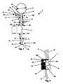
- FIG. 1illustrates an embodiment of the implantable dialysis device.
- FIG. 2illustrates cross-section A-A of an embodiment of the distributor.
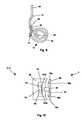
- FIG. 3illustrates an embodiment of the implantable dialysis device.
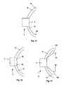
- FIG. 4illustrates cross-section B-B of an embodiment of the distributor.
- FIG. 5illustrates cross-section C-C of an embodiment of the distributor.
- FIG. 6illustrates an embodiment of the implantable dialysis device.
- FIG. 7illustrates cross-section D-D of an embodiment of the distributor.
- FIG. 8illustrates an embodiment of the implantable dialysis device.
- FIG. 9illustrates an embodiment of the exit conduit and the exit.
- FIG. 10illustrates cross-section C-C of an embodiment of the distributor.
- FIGS. 11-13illustrate various embodiments of the implantable dialysis device.
- FIGS. 14 and 15illustrate various embodiments of the transfer element.
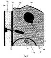
- FIG. 16illustrates a method and placement for implanting the implantable dialysis device.
- FIGS. 17-22illustrate an embodiment of a method for peritoneal dialysis using the implantable dialysis device.
- FIGS. 23-27illustrate an embodiment of a method for peritoneal dialysis using the implantable dialysis device.
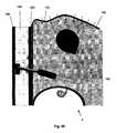
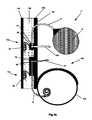
- FIGS. 28-32illustrate various embodiments of a method for peritoneal dialysis using the implantable dialysis device.
- FIG. 33illustrates an embodiment of a method for using the implantable dialysis device having a mixing chamber.
- FIG. 34illustrates an embodiment of a method for using the implantable dialysis device having a inductive dipole transducer.
- FIG. 35illustrates an embodiment of a method for using the implantable dialysis device implanted wholly in the peritoneal cavity and the bladder.
- FIG. 36illustrates an embodiment of a method for using the implantable dialysis device with a first component and a second component.
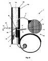
- FIG. 1illustrates an implantable dialysis device 2 .
- the implantable dialysis device 2can have a distributor 4 .
- the distributor 4can be configured to receive and distribute a dialysate and/or any other fluid or fluids, for example a solution of therapeutic and or diagnostic agents.
- the dialysatecan be received by the distributor 4 and initially distributed through a reservoir conduit 6 to a reservoir 8 .
- the distributor 4can withdraw the dialysate from the reservoir 8 and distribute the dialysate through a discharge conduit 10 to a peritoneal cavity (shown infra).
- the distributor 4can withdraw the dialysate and other waste fluids and solids from the peritoneal cavity through the discharge conduit 10 .
- the distributor 4can then distribute the withdrawn dialysate and waste fluids and solids through the exit conduit 12 and out an exit 14 to a bladder (shown infra).
- the distributor 4can be attached to a reservoir conduit 6 .
- the reservoir conduit 6can be attached to the reservoir 8 .
- a reservoir connector 18can attach the reservoir conduit 6 to the reservoir 8 .
- the reservoir 8can be in fluid communication with a reservoir conduit first end 20 a .
- the reservoir connector 18can reinforce the attachment between the reservoir 8 and the reservoir conduit first end 20 a
- the reservoir 8can be a substantially or completely impermeable, leak-proof container for indefinite storage of therapeutic and/or diagnostic fluids and/or solids.
- the reservoir 8can be hollow.
- a reservoir sensor 22such as a reservoir pressure sensor, reservoir pH sensor, reservoir temperature sensor, reservoir electrolyte sensor, reservoir analyte sensor, or combinations thereof, can be attached to the inside of the reservoir 8 .
- the reservoir 8can be substantially spherical, circular, cylindrical, tubular, or have a shape similar to a partially flattened sphere.
- the reservoir 8can be shaped to fit in the negative space around organs, for example in the cul-de-sac of the peritoneal cavity.
- the reservoir 8can be made from at least two pieces of material. The pieces of material can be joined at the perimeters of the pieces of material. The pieces of material can be substantially circular.
- the reservoir 8can have a reservoir diameter 24 .
- the reservoir diameter 24can be from about 2 cm (0.8 in.) to about 20 cm (8 in.), more narrowly from about 4 cm (2 in.) to about 10 cm (4 in.), for example about 2 cm (0.8 in.), about 4 cm (2 in.), about 10 cm (4 in.), or about 20 cm (8 in.).
- the reservoir 8can have a reservoir volume.
- the reservoir volumecan be from about 10 mL (0.6 in. 3 ) to about 3000 mL (200 in. 3 ), more narrowly from about 200 mL (10 in. 3 ) to about 2000 mL (100 in. 3 ), for example about 1500 mL (92 in. 3 ).
- the reservoir volumecan depend on the potency (e.g., solute concentration) of the reservoir contents used with the reservoir 8 .
- the reservoir 8can be substantially impermeable, for example the outer surface of the reservoir 8 can be made from a nonporous membrane or a membrane with sufficiently small pores to minimize or prevent flow across the surface of the reservoir 8 .
- the pore sizecan be dependent on the particle size of an agent (e.g., osmotic agent, dialysate) dispensed into the surrounding body cavity and/or tissue.
- the pore sizecan prevent leakage, for example, of particles with a molecular weight (MW) from about 50 to about 5000, more narrowly a MW less than about 800, yet more narrowly a MW from about 50 to about 100.
- the porescan be configured to exclude, for example, sugars and dialysates (e.g., with a MW of about 800), synthetic osmotic agents (e.g., a.
- MW of less than or equal to about 5000glucose (e.g., about 2.27% solution, MW of about 180.16), maltose, such as maltose disaccharide (e.g., about 4.32% solution, MW of about 342.30), maltotriose, such as maltotriose trisaccharide (e.g., about 6.36% solution, MW of about 504.44), and maltopentaose, such as maltopentaose pentasaccharide (e.g., about 10.4% solution, MW of about 828.72), any other osmotically active material, and combinations thereof.
- maltosesuch as maltose disaccharide (e.g., about 4.32% solution, MW of about 342.30)
- maltotriosesuch as maltotriose trisaccharide (e.g., about 6.36% solution, MW of about 504.44)
- maltopentaosesuch as maltopentao
- the reservoir 8can have pores having diameters substantially smaller than about 500 ⁇ m (19.7 mil), yet more narrowly from about 5 ⁇ m (0.2 mil) to about 200 ⁇ m (7.87 mil). (“Substantially smaller” can be having about 95% or more of the pores being smaller.)
- the reservoir 8can have an average pore diameter from about 5 ⁇ m (0.2 mil) to about 500 ⁇ m (1.97 mil), for example about 10 ⁇ m (0.39 mil).
- the reservoir 8can be made from any of the materials disclosed infra for all elements of the implantable dialysis device 2 .
- the reservoir 8can be made from a biocompatible impermeable membrane.
- the reservoir 8can be made from, for example polymers, such as polyacrylonitrile (PAN), polysulfone (PS), polyethersulfone, poluethylene, polymethylmethacrylate (PMMA), polytetrafluoroethylene (PTFE) (e.g., TEFLON®, E.I. Du Pont de Nemours and Company, Wilmington, Del.), expanded PTFE (ePTFE) (e.g., GORE-TEX® from W.L. Gore & Associates, Inc., Newark, Del.), polyester (e.g., DACRON® from E.I.
- PANpolyacrylonitrile
- PSpolysulfone
- PMMApolymethylmethacrylate
- PTFEpolytetrafluoroethylene
- ePTFEexpanded PTFE
- polyestere.g., DACRON® from E.I.
- polypropylenepolyether ether ketone (PEEK), Nylon, polyether-block co-polyamide polymers (e.g., PEBAX® from ATOFINA, Paris, France), polyurethanes such as aliphatic polyether polyurethanes (e.g., TECOFLEX® from Thermedics Polymer Products, Wilmington, Mass.), polyvinyl chloride (PVC), thermoplastic, fluorinated ethylene propylene (FEP), cellulose (e.g., VISKING®, SERVAPOR®, MEMBRA-CEL®, or SPECTRA/POR® 1, 3 and 6 Dialysis Tubing from SERVA Electrophoresis GmbH of Heidelberg, Germany; Cuprophane PT-150 from Enka-Glanstoff of Germany) such as a seamless regenerated cellulose and/or cellulose acetate (CA), extruded collagen, silicone, a metal, such as single or multiple stainless steel alloys, nickel
- the reservoir 8as well as other elements in contact with the stored fluids, for example the elements from a filling port to the reservoir 8 and from the reservoir 8 to the distributor 4 , can be made from strong and/or redundant materials having a thickness and construction such that the material can remain intact without leaking or becoming substantially permeable during conditions of extreme acceleration, for example in a halting car accident at about 89 km/h (55 miles per hour) producing, for example, an acceleration of about 991.5 m/s 2 (3,253 f/s 2 ).
- the reservoir 8can be made from a multi-layer and/or fiber-reinforced material.
- the reservoir 8can be made from strong and redundant materials.
- the reservoir 8can be made from a flexible or rigid material.
- the reservoir conduit 6can be configured to enable the fluid communication of dialysate or other fluid between the distributor 4 and the reservoir 8 .
- the reservoir 8can be fixedly, removably and/or rotatably attached, directly or indirectly, to the reservoir conduit first end 20 a .
- the reservoir 8can be in fluid communication with the reservoir conduit first end 20 a .
- the distributor 4can be attached to a reservoir conduit second end 20 b .
- the distributor 4can be in fluid communication with the reservoir conduit second end 20 b.
- the reservoir conduit 6can be flexible or rigid.
- the reservoir conduit 6can be deformable or resilient.
- the reservoir conduit 6can be substantially impermeable.
- the reservoir conduit 6can have a reservoir conduit diameter 26 and a reservoir conduit length 28 .
- the reservoir conduit diameter 26can be from about 1 mm (0.04 in.) to about 10 mm (0.4 in.), more narrowly from about 2 mm (0.08 in.) to about 5 mm (0.2 in.), for example about 1 mm (0.04 in.), about 2 mm (0.08 in.), about 5 mm (0.2 in.), or about 10 mm (0.4 in.).
- the reservoir conduit length 28can be from about 0 cm (0 in.) to about 50 cm (20 in.), more narrowly from about 5 cm (2 in.) to about 20 cm (8 in.), for example about 5 cm (2 in.), about 10 cm (4 in.), about 20 cm (8 in), or about 50 cm (20 in.).
- the discharge conduit 10can be configured to enable fluid communication of dialysate, waste liquids and solids, and/or other fluid between the distributor 4 and the peritoneal cavity.
- the peritoneal cavitycan be in fluid communication with a discharge conduit first port 30 at a discharge conduit first end 32 a .
- the distributor 4can be attached to a discharge conduit second end 32 b .
- the distributor 4can be in fluid communication with the discharge conduit second end 32 b.
- the discharge conduit 10can be substantially impermeable, permeable, semi-permeable or combinations thereof.
- the discharge conduit first port 30can have an opening, and/or a permeable, and/or a semi-permeable surface.
- the discharge conduit 10can have multiple (not shown) discharge conduit first ports 30 that can be at the discharge conduit first end 32 a and/or along a discharge conduit length 34 .
- the discharge conduit first port 30can be configured to minimize and/or prevent fluid communication of proteins, for example by size or charge exclusion (e.g., as described in detail supra for the reservoir and infra for the transfer element and barriers).
- a peritoneal cavity sensor 36such as a peritoneal cavity pressure sensor, peritoneal cavity pH sensor, peritoneal cavity temperature sensor, peritoneal cavity electrolyte sensor, peritoneal cavity analyte sensor, or combinations thereof, can be attached to the discharge conduit 10 , for example on or adjacent to the discharge conduit first port 30 .
- the discharge conduit 10can have one or more perforations 38 along part or all of the discharge conduit length 34 .
- the perforations 38can be along the discharge conduit first end 32 a and/or along the discharge conduit second end 32 b .
- the perforations 38can be configured to allow the fluid communication of the dialysate or other fluids.
- the perforations 38can be configured to minimize and/or prevent fluid communication of proteins for example by size or charge exclusion (e.g., as described herein).
- the perforations 38can be configured to minimize and/or prevent fluid communication of dialysate solute.
- the discharge conduit 10can be flexible or rigid.
- the discharge conduit 10can be deformable or resilient.
- the discharge conduit 10can have a discharge conduit diameter 40 and the discharge conduit length 34 .
- the discharge conduit diameter 40can be from about 1 mm (0.04 in.) to about 10 mm (0.4 in.), more narrowly from about 2 mm (0.08 in.) to about 5 mm (0.2 in.), for example about 1 mm (0.04 in.), about 2 mm (0.08 in.), about 5 mm (0.2 in.), or about 10 mm (0.4 in.).
- the discharge conduit length 34can be from about 0 cm (0 in.) to about 50 cm (20 in.), more narrowly from about 5 cm (2 in.) to about 20 cm (8 in.), for example about 5 cm (2 in.), about 10 cm (4 in.), about 20 cm (8 in), or about 50 cm (20 in.).
- the discharge conduit 10can be shaped to fit in the negative space around one or more organs within the peritoneal cavity.
- the discharge conduit 10can permit the inflow of bodily fluids required to mix with dialysate fluid (e.g., in concentrated form) or solid dialysate material prior to transfer into the peritoneal cavity.
- the outer surface of the reservoir conduit 6can be attached to the outer surface of the discharge conduit 10 along the entire, part, or none of the reservoir conduit length 28 and the discharge conduit length 34 .
- the reservoir conduit 6 and the discharge conduit 10can share a common outer conduit (not shown) along the entire or part of the reservoir conduit length 28 and the discharge conduit length 34 .
- the common outer conduitcan be distinct or integral with the reservoir conduit 6 and/or the discharge conduit 10 .
- the exit conduit 12can be configured to enable the fluid communication of dialysate or other fluid between the distributor 4 and the bladder.
- the distributor 4can be fixedly, removably and/or rotatably attached, directly or indirectly, to an exit conduit first end 42 a .
- the distributor 4can be in fluid communication with the exit conduit first end 42 a .
- the bladder(shown infra) can be attached to an exit conduit second end 42 b , for example by fixedly attaching an anchor 44 at the exit conduit second end 42 b against a wall of the bladder.
- the anchor 44can have a flange that can form a one-way interference fit with the wall of the bladder.
- the bladderfor example via an exit port 46 , can be in fluid communication with the exit conduit second end 42 b .
- a bladder sensor 48such as a bladder pressure sensor, bladder pH sensor, bladder temperature sensor, bladder electrolyte sensor, bladder analyte sensor, or combinations thereof, can be attached to the exit conduit 12 , for example on or adjacent
- the exit conduit 12can be substantially impermeable (e.g., outside the bladder) and/or semi-permeable (e.g., inside the bladder) and/or permeable (e.g., inside the bladder).
- the exit conduit 12can be flexible or rigid.
- the exit conduit 12can be deformable or resilient.
- the exit conduit 12can have an exit conduit diameter 50 and an exit conduit length 52 .
- the exit conduit diameter 50can be from about 1 mm (0.04 in.) to about 10 mm (0.4 in.), more narrowly from about 2 mm (0.08 in.) to about 5 mm (0.2 in.), for example about 1 mm (0.04 in.), about 2 mm (0.08 in.), about 5 mm (0.2 in.), or about 10 mm (0.4 in.).
- the exit conduit length 52can be from about 0 cm (0 in.) to about 50 cm (20 in.), more narrowly from about 5 cm (2 in.) to about 20 cm (8 in.), for example about 5 cm (2 in.), about 10 cm (4 in.), about 20 cm (8 in), or about 50 cm (20 in.).
- the exit conduit 12can be distinct from the reservoir conduit 6 and/or the discharge conduit 10 .
- the exit conduit 12can be integral with the reservoir conduit 6 and/or the discharge conduit 10 .
- the exit conduit 12can be in fluid communication with the reservoir conduit 6 and/or the discharge conduit 10 .
- any or all elements of the implantable dialysis device 2can be made from, for example, a single or multiple stainless steel alloys, nickel titanium alloys (e.g., Nitinol), cobalt-chrome alloys (e.g., ELGILOY® from Elgin Specialty Metals, Elgin, Ill.; CONICHROME® from Carpenter Metals Corp., Wyomissing, Pa.), molybdenum alloys (e.g., molybdenum TZM alloy, for example as disclosed in International Pub. No. WO 03/082363 A2, published 9 Oct. 2003), tungsten-rhenium alloys, for example, as disclosed in International Pub. No.
- polymerssuch as polyester (e.g., DACRON® from E.I. Du Pont de Nemours and Company, Wilmington, Del.), polypropylene, PTFE, ePTFE, PEEK, Nylon, polyether-block co-polyamide polymers (e.g., PEBAX® from ATOFINA, Paris, France), polyurethenes such as aliphatic polyether polyurethanes (e.g., TECOFLEX® from Thermedics Polymer Products, Wilmington, Mass.), PVC, PAN, PS, polyethersulfone, polyethylene, polymethylmethacrylate (PMMA), thermoplastic, FEP, cellulose (e.g., VISKING®, SERVAPOR®, MEMBRA-CEL®, or SPECTRA/POR® 1, 3 and 6 Dialysis Tubing from SERVA Electrophoresis GmbH of Heidelberg, Germany; Cuprophane PT-150 from Enka-Glanstoff of Germany), such as a seamless regenerated
- any or all elements of the implantable dialysis device 2can be a matrix for cell ingrowth or used with a fabric, for example a covering (not shown) that acts as a matrix for cell ingrowth.
- the matrix and/or fabriccan be, for example, polyester (e.g., DACRON® from E.I. du Pont de Nemours and Company, Wilmington, Del.), polypropylene, PTFE, ePTFE, nylon, extruded collagen, silicone or combinations thereof.
- the elements of the implantable dialysis device 2 and/or the fabriccan be filled and/or coated with an agent delivery matrix known to one having ordinary skill in the art and/or a therapeutic and/or diagnostic agent.
- the agents within these matricescan include radioactive materials; radiopaque materials; cytogenic agents; cytotoxic agents; cytostatic agents; thrombogenic agents, for example polyurethane, cellulose acetate polymer mixed with bismuth trioxide, and ethylene vinyl alcohol; lubricious, hydrophilic materials; phosphor cholene; anti-inflammatory agents, for example non-steroidal anti-inflammatories (NSAIDs) such as cyclooxygenase-1 (COX-1) inhibitors (e.g., acetylsalicylic acid, for example ASPIRIN® from Bayer AG, Leverkusen, Germany; ibuprofen, for example ADVIL® from Wyeth, Collegeville, Pa.; indomethacin; mefenamic acid),
- the reservoir 8can be made from any of the materials disclosed herein for all elements of the implantable dialysis device 2 .
- the reservoir 8can be made from a biocompatible impermeable membrane.
- the reservoir 8can be made from, for example, silicone, cellulose (e.g., VISKING®, SERVAPOR®, MEMBRA-CEL®, or SPECTRA/POR® 1, 3 and 6 Dialysis Tubing from SERVA Electrophoresis GmbH of Heidelberg, Germany; Cuprophane PT-150 from Enka-Glanstoff of Germany), such as a seamless regenerated cellulose and CA, extruded collagen, silicone, polymers, such as PAN, PS, polyethersulfone, polyether ether ketone (PEEK), Nylon, polyether-block co-polyamide polymers (e.g., PEBAX® from ATOFINA, Paris, France), polyurethanes such as aliphatic polyether polyurethanes (e.g., TECOFLEX® from Thermedics Polymer Products, Wilmington, Mass.), polyvinyl chloride (PVC), poluethylene, polyester (e.g., DACRON® from E.I.
- siliconee.g
- Nitinolnickel titanium alloys
- cobalt-chrome alloyse.g., ELGILOY®; CONICHROME®
- molybdenum alloyse.g., molybdenum TZM alloy
- tungsten-rhenium alloysor combinations of any of the above.
- the reservoir 8can be made from an non-permeable material.
- the reservoir 8can be made from a material having a thickness and construction such that the material can remain intact without leaking or becoming substantially permeable during conditions of extreme acceleration, for example in a halting car accident at about 89 km/h (55 miles per hour) producing, for example, an acceleration of about 991.5 m/s 2 (3,253 f/s 2 ).
- the reservoir 8can be made from a multi-layer and/or fiber-reinforced material.
- the reservoir 8can be made from a rigid material.
- the reservoir 8can be made from any material listed herein, for example, polymers such as polyester (e.g., DACRON® from E. I.
- PTFEpolytetrafluoroethylene
- ePTFEexpanded PTFE
- polyether ether ketonePEEK
- Nylonpolyether-block co-polyamide polymers
- polyurethanessuch as aliphatic polyether polyurethanes (e.g., TECOFLEX® from Thermedics Polymer Products, Wilmington, Mass.), PVC, PAN, PS, polyethersulfone, polyethylene, PMMA, thermoplastic, FEP, cellulose (e.g., VISKING®, SERVAPOR®, MEMBRA-CEL®, or SPECTRA/POR® 1, 3 and 6 Dialysis Tubing from SERVA Electrophoresis GmbH of Heidelberg, Germany; Cuprophane PT-150 from Enka-Glanstoff of Germany), such as a seamless regenerated cellulose and/or CA, extruded collagen, silicone or combinations thereof.
- PEBAX®from ATOFINA, Paris, France
- polyurethanessuch as aliphatic polyether polyurethanes (e.g., TECOFLEX® from Thermedics Polymer
- the implantable dialysis device 2can have one or more reservoir sensors 22 .
- the reservoir sensors 22can be in the reservoir 8 , and/or in the reservoir connector 18 , and/or in the reservoir conduit 6 .
- the reservoir sensors 22can be configured to measure pressure, pH, temperature, electrolyte concentration, analyte concentration, or combinations thereof in the reservoir 8 .
- the implantable dialysis device 2can have one or more peritoneal cavity sensors 36 .
- the peritoneal cavity sensors 36can be on the discharge conduit 10 , for examples, at the discharge conduit first end 32 a and/or along the discharge conduit length 34 .
- the peritoneal cavity sensors 36can be configured to measure pressure, pH, temperature, electrolyte concentration, analyte concentration, or combinations thereof in the peritoneal cavity.
- the implantable dialysis device 2can have one or more bladder sensors 48 .
- the bladder sensors 48can be on the exit 14 .
- the bladder sensors 48can be configured to measure pressure, pH, temperature, electrolyte concentration, analyte concentration, or combinations thereof in the bladder.
- the sensors 22 , 36 , and 48can measure concentration of dialysate solutes in the fluids.
- the sensors 22 , 36 , and 48can send signals indicating respective measured metrics to the distributor 4 .
- FIG. 2illustrates that the distributor 4 can have a pump 54 .
- the pump 54can be a mechanical, electromechanical, osmotic or diffusion pump, or combinations thereof.
- the pump 54can be a hand-powered pump, for example the pump can be a resilient, compressible bulb pump.
- the pump 54can be a miniature gear-pump.
- the pump 54can be strong enough to clear clogs from the discharge conduit 10 and/or the exit conduit 12 .
- the pump 54can produce a flow rate in the discharge conduit 10 from about 50 mL/min. (3.0 in. 3 /min.) to about 5000 mL/min. (300 in. 3 /min.), more narrowly from about 250 mL/min. (15 in. 3 /min.) to about 500 mL/min. (30 in. 3 /min.).
- the flow ratecan be set to prevent bladder spasm with the rapid influx of the fluid.
- the pump 54can have and/or be in fluid communication with a distributor valve 56 (shown infra).
- the distributor valve 56can be a mechanical valve, a semi-permeable membrane or combinations thereof.
- the distributor valve 56can be a single, three-way valve.
- the distributor 4can have a distributor first conduit 58 a
- the distributor first conduit 58 acan be in fluid communication with the reservoir conduit second end 20 b .
- the distributor first conduit 58 acan be in fluid communication with the distributor valve 56 .
- the distributor first conduit 58 acan be integral with the reservoir conduit second end 20 b.
- the distributor 4can have a distributor second conduit 58 b .
- the distributor second conduit 58 bcan be in fluid communication with the discharge conduit 10 .
- the distributor second conduit 58 bcan be in fluid communication with the distributor valve 56 .
- the distributor second conduit 58 bcan be integral with the discharge conduit 10 .
- the distributor 4can have a distributor third conduit 58 c .
- the distributor third conduit 58 ccan be in fluid communication with the exit conduit first end 42 a
- the distributor third conduit 58 ccan be in fluid communication with the distributor valve 56 .
- the distributor third conduit 58 ccan be integral with the exit conduit first end 42 a.
- the distributor valve 56can be configured to route flow between a distributor first conduit 58 a , the distributor second conduit 58 b , and the distributor third conduit 58 c .
- the distributor valve 56can be configured as a one-way flow or check valve, for example, preventing backflow in any direction.
- the distributor valve 56can be a one-way valve preventing flow in the direction from the distributor third conduit 58 c to either the distributor first conduit 58 a or the distributor second conduit 58 b.
- the distributor valve 56can be a pressure sensing valve.
- the distributor valve 56can be configured to shut off flow if backpressure exceeds a pre-determined threshold. If pressure in the peritoneal cavity is less than about 1.5 kPa (0.15 psi), more narrowly less than about 1 kPa (0.1 psi), yet more narrowly less than about 0.5 kPa (0.07 psi), then the pump 54 can be inhibited (e.g., stopped or slowed), for example be the distributor valve 56 and/or a controller.
- the pump 54can be inhibited. If the differential between the pressure in the peritoneal cavity and the pressure in the bladder pressure is greater than or equal to about 2 kPa (0.3 psi), more narrowly greater than or equal to about 3 kPa (0.4 psi), then the pump 54 can be inhibited.
- the distributor 4can have a power storage and/or regulation device, for example a battery 60 .
- the battery 60can be configured to supply power to the pump 54 and/or the distributor valve 56 .
- the battery 60can be one or more power storage devices (not shown), for example capacitors, dry or wet cells, flywheels, springs, or combinations thereof.
- the battery 60can hold a charge of more than about 500 mAh, for example about 1000 mAh.
- 3 AA Nickel Cadmium about 1000 mAh batteriescan be used.
- the battery 60can be configured to provide a current of greater than about 0.2 DCA and/or less than about 2.0 DCA, for example about 0.42 DCA.
- the distributor 4can have an internal transducer 62 .
- the internal transducer 62can receive energy in a first form (e.g. moving magnetic fields), convert the energy into a second form (e.g., direct current electricity), and deliver the second form of energy to appropriate elements (e.g., pump 54 , distributor valve 56 , controller) in the implantable dialysis device 2 .
- the internal transducer 62can be wholly or partially inside a distributor case.
- An internal transducer connector 64(shown infra) can be configured to deliver the energy to the appropriate elements.
- the internal transducer connector 64can be wholly within the distributor case.
- the distributor 4can have an internal filling port 66 .
- the internal filling port 66can have a self-sealing membrane forming at least part of the external wall of the distributor 4 .
- the internal filling port 66can be configured to receive injections (e.g., of dialysate solution and/or other agent), for example from a transcutaneous needle.
- the internal filling port 66can have a locating mechanism, for example, a magnetic field or another signal generating mechanism. The locating mechanism can aid targeting the internal filling port 66 , for example, when injecting dialysate solution and/or other agent.
- the internal filling port 66can have a storage volume.
- the internal filling port 66can have a non-corrosive internal surface.
- the internal filling port 66can be a receptacle for a cartridge or ampoule.
- a filling conduit 68can be configured to create fluid communication between the internal filling port 66 and the reservoir conduit 6 .
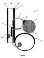
- FIG. 3illustrates the implantable dialysis device 2 that can have a first component 72 a and a second component 72 b .
- the first component 72 acan be physically unattached to the second component 72 b.
- the first component 72 acan be configured to pump fluid from a drainage conduit 74 to, and out, the exit conduit 12 .
- the drainage conduit 74can have a drainage conduit first port 75 .
- the first component 72 acan have a first distributor 4 a
- the first distributor 4 acan be attached to the drainage conduit 74 .
- the first distributor 4 acan be attached to the exit conduit 12 .
- the second component 72 bcan be configured to receive a solution, for example, dialysate by injection into a second distributor 4 b .
- the second component 72 bcan be configured to deliver and store the solution in the reservoir 8 .
- the second component 72 bcan be configured to deliver the stored solution from the reservoir 8 to, and out, the discharge conduit 10 .
- the second distributor 4 bcan be attached to the reservoir conduit 6 and the reservoir 8 .
- the second distributor 4 bcan be attached to the discharge conduit 10 .
- the first component 72 acan be in data and/or power communication with the second component 72 b .
- One or more wirescan attach the first component 72 a to the second component 72 b .
- the first component 72 acan communicate with the second component 72 b over a data network, for example, a wired and/or wireless network, such as Ethernet (IEEE 802.3), Firewire (IEEE 1394), 802.11 (wireless LAN), Bluetooth, cellular communication, serial port (RS-232, RS485), parallel port (IEEE 1284), Fiber Channel, IRDA infrared data port, radio such as 900 MHz RF or FM signal, or combinations thereof.
- a wired and/or wireless networksuch as Ethernet (IEEE 802.3), Firewire (IEEE 1394), 802.11 (wireless LAN), Bluetooth, cellular communication, serial port (RS-232, RS485), parallel port (IEEE 1284), Fiber Channel, IRDA infrared data port, radio such as 900 MHz RF or FM signal
- Any implantable dialysis device 2can also use the communication networks supra to communicate data with an extracorporeal component, for example, a monitoring device such as a handheld diagnostic computer or peripheral device (e.g., a personal data assistant).
- the extracorporeal componentcan transmit and receive data and/or energy from the implantable dialysis device 2 (e.g., from the internal transducer 62 and/or controller and/or battery 60 ).
- the extra corporeal componentcan be used to control operation of, or provide an energy charge to, the implantable dialysis device 2 .
- FIG. 4illustrates the first distributor 4 a that can have no internal filling port 66 .
- the first distributor 4 acan have no distributor third conduit 58 c .
- the exterior of the distributor 4can be the distributor case 76 .
- the distributor case 76can be made from, coated, or otherwise surrounded with a biocompatible material.
- the distributor 4can have a distributor first port 78 a and a distributor second port 78 b .
- the distributor ports 78 a and 78 bcan be voids in the distributor case 76 , semi-permeable membranes, permeable membranes, or combinations thereof.
- the distributor first port 78 acan be fixedly or releasably attached to a conduit, for example, the drainage conduit 74 .
- the distributor second port 78 bcan be fixedly or releasably attached to a conduit, for example the exit conduit 12 .
- a distributor first port 78 acan be fixedly or releasably attached to and/or integral with, and in fluid communication with, the drainage conduit 74 .
- a distributor second port 78 bcan be fixedly or releasably attached to and/or integral with, and in fluid communication with, the exit conduit 12 .
- the distributor valve 56can be a one-way check valve permitting flow from the distributor first port 78 a to the distributor second port 78 b , but preventing or minimizing flow from the distributor second port 78 b to the distributor first port 78 a.
- the internal transducer 62can be outside the distributor case 76 .
- the internal transducer 62can be an induction coil.
- the internal transducer connector 64can connect the internal transducer 62 to the pump 54 and/or to one or more power storage devices (not shown), for example capacitors, dry or wet cells, flywheels, springs, or combinations thereof.
- the internal transducer connector 64can pass through the distributor case 76 .
- any or each distributor 4can have a separate pump 54 .
- FIG. 5illustrates that the second distributor 4 b can have the storage volume of the internal filling port 66 surrounding the pump 54 .
- the distributor case 76can be a self-sealing material configured to allow a needle puncture in one or more locations.
- the reservoir conduit second end 20 b(not shown) can be fixedly or releasably attached to and/or integral with, and in fluid communication with, the distributor first port 78 a .
- the discharge conduit second end 32 b(not shown) can be fixedly or releasably attached to and/or integral with, and in fluid communication with, the distributor second port 78 b.
- FIG. 6illustrates the implantable dialysis device 2 that can have a first discharge conduit 10 a and a second discharge conduit 10 b .
- the first and second discharge conduits 10 a and 10 bcan have first and second discharge conduit lengths 34 a and 34 b and first and second discharge conduit diameters 40 a and 40 b that can be equivalent to those supra for the discharge conduit 10 .
- the first and/or second discharge conduits 10 a and/or 10 bcan have first and/or second peritoneal cavity sensors 36 a and/or 36 b , respectively.
- the first and/or second discharge conduits 10 a and/or 10 bcan have a first and/or second discharge conduit first port guards 80 a and/or 80 b .
- the guards 80 a and 80 bcan be rigid, semi-rigid or flexible.
- the port guards 80 a and 80 bcan be wire screens, permeable membranes, or combinations thereof.
- the port guards 80 a and 80 bcan be configured to filter particles based on size and/or charge.
- FIG. 7illustrates that the distributor 4 can have the distributor first conduit 58 a , the distributor second conduit 58 b , and the distributor third conduit 58 c that can be segmented from a single channel, and/or be adjacent to each other.
- the distributor first, second, and third conduits 58 a , 58 b and 58 ccan all open on the same side of the distributor 4 .
- the distributor 4can have a distributor fourth conduit 58 d .
- the distributor fourth conduit 58 dcan open on a different side of the distributor 4 than the first, second and third conduits 70 a , 70 b and 70 c.
- the reservoir conduit second end 20 bcan be fixedly or releasably attached to and/or integral with, and in fluid communication with, the distributor first conduit 58 a
- the first discharge conduit second end 32 b ′can be fixedly or releasably attached to and/or integral with, and in fluid communication with, the distributor second conduit 58 b .
- the second discharge conduit second end 32 bcan be fixedly or releasably attached to and/or integral with, and in fluid communication with, the distributor third conduit 58 c .
- the fourth conduit 58 dcan be fixedly or releasably attached to and/or integrated with, and in fluid communication with, the exit conduit 12 .
- FIG. 8illustrates that the implantable dialysis device 2 can have the first and second distributors 4 a and 4 b .
- the reservoir conduit 6can have an inflow channel 86 and an outflow channel 88 .
- the inflow and outflow channels 86 and 88can be separated by a septum, be otherwise attached or integral, or be contained within two distinct, and separate tubes.
- the inflow channel 86can be attached to the outflow channel 88 along part or all of the lengths of the inflow channel 86 and the outflow channel 88 .
- the inflow channel 86can provide fluid communication between the internal filling port 66 and the reservoir 8 .
- the internal filling port 66 and/or filling conduit(not shown in FIG. 8 ) can be attached to the inflow channel 86 .
- the reservoir 8 and/or the reservoir connector 18can be attached to the inflow channel 86 .
- the inflow channel 86can be attached to and/or integral with the reservoir 8 and the second distributor 4 b , for example with the internal filling port 66 .
- the inflow channel 86can be in direct fluid communication with, and/or attached to, the first distributor 4 a
- the first distributor 4 acan be configured to provide a positive and/or negative pressure to the inflow channel 86 .
- the outflow channel 88can be in direct fluid communication with, and attached to and/or integral with the first distributor 4 a and the reservoir 8 and/or the reservoir connector 18 .
- the discharge conduit 10can have one or more perforations 38 along part or all of the discharge conduit length 34 .
- the perforations 38can be along the discharge conduit first end 32 a and/or along the discharge conduit second end 32 b .
- the perforations 38can be configured to allow the fluid communication of dialysate solute.
- the perforations 38can be configured to disallow fluid communication of proteins.
- the perforations 38can be configured to disallow fluid communication of dialysate solute.
- the first distributor 4 acan have the pump 54 (not shown).
- the second distributor 4 bcan have the internal filling port 66 .
- the second distributor 4 bcan have the internal transducer 62 .
- the internal transducer connector 64can be attached to the first distributor 4 a and/or the second distributor 4 b .
- the internal transducer connector 64can transfer power from the second distributor 4 b to the first distributor 4 a .
- the first and/or second distributors 4 a and/or 4 bcan have the batteries 60 (not shown in FIG. 8 ).
- FIGS. 8 and 9illustrate that the exit conduit 12 can have an exit extension 90 .
- the exit extension 90can be semi-permeable, permeable, impermeable, or combinations thereof.
- the exit extension 90can have a length of conduit, for example a coiled or “pigtail” catheter.
- the exit extension 90can have one or more exit ports 46 .
- the exit extension 90can have an exit tip 94 .
- the exit tip 94can have the exit port 46 (not shown in FIG. 8 or 9 ).
- the exit tip 94can be semi-permeable, impermeable, permeable, or combinations thereof.
- the exit conduit 12can have an exit conduit longitudinal axis 96 .
- the exit conduit 12can have one or more sub-anchors 98 .
- the sub-anchors 98can be substantially perpendicular to the exit conduit longitudinal axis 96 .
- the anchor 44can be substantially perpendicular to the exit conduit longitudinal axis 96 .
- the sub-anchors 98can be flanges.
- the sub-anchors 98can be rigid or flexible.
- FIG. 10illustrates that the pump 54 can have or be mechanically attached to a rotational electromechanical motor 99 .
- the motor 99can be configured to be inductively driven.
- the motor 99can have a first pole 100 a and a second pole 100 b .
- a pole axle 102can attach the first pole 100 a to the second pole 100 b .
- the pole axle 102can rotate about a motor rotation axis 104 , for example when the first and second poles 100 a and 100 b are urged by a dynamic external magnetic field.
- the pole axle 102can be mechanically coupled to a flow driving mechanism (not shown).
- the pump 54 and/or motor 99can be the taught by PCT Patent Application No. PCT/US2004/026781 titled Magnetic Circumferentially Coupled Implantable Pump, filed 18 Aug. 2004, and hereby incorporated by reference in its entirety.
- FIGS. 11 through 13illustrate various configurations of the peritoneal cavity sensor 36 and bladder sensor 48 .
- the peritoneal cavity sensor 36 and bladder sensor 48can be in fluid communication with the discharge conduit 10 and/or exit conduit 12 , respectively (i.e., and the peritoneal cavity and the bladder, respectively, during use).
- the peritoneal cavity sensor 36 and bladder sensor 48can be attached to the discharge conduit 10 and exit conduit 12 .
- the peritoneal cavity sensor 36 and the bladder sensor 48can be on the inside (as shown) and/or outside of the discharge and exit conduits 10 and 12 . As shown in FIG.
- the peritoneal cavity sensor 36 and bladder sensor 48can be located in the distributor 4 .
- the peritoneal cavity sensor 36can be attached to a peritoneal tether 106 .
- the bladder sensor 48can be attached to a bladder tether 108 .
- Multiple sensors 36 and 48can be attached to each tether 106 and 108 .
- the tethers 106 and 108can be attached to the respective conduits 10 and 12 , and/or the distributor 4 , and/or to other elements of the implantable dialysis device 2 .
- the tethers 106 and 108can be flexible or rigid.
- the implantable dialysis device 2can have more than one of each peritoneal cavity sensor 36 and bladder sensor 48 .
- the peritoneal cavity sensor 36 and bladder sensor 48can be in any combination of configurations.
- FIGS. 14 and 15illustrate that the implantable dialysis device 2 can have a transfer element 110 at the first end of the drainage (e.g., shown without the transfer element 110 in FIG. 3 ) and/or discharge (e.g., shown without the transfer element 110 in FIG. 6 ) conduits 74 and/or 10 .
- the transfer element 110can be integral with, and/or attached to, the conduits 74 and/or 10 via a transfer element connector 111 .
- the transfer element 110can have a permeable surface.
- the transfer element 110can be configured to filter peritoneal fluids across a transfer element face 112 .
- the transfer element 110can be configured to filter fluid across the transfer element face 112 through size and/or 1 charge exclusion.
- the transfer element 110can be configured to allow water and waste in the peritoneal fluid to osmotically transfer into the transfer element 110 .
- FIG. 14illustrates that the transfer element 110 can be configured to resiliently expand and compress, as shown by arrows.
- the transfer element 110can be configured to transfer liquids out of the transfer element 110 and into the drainage and/or discharge conduits 74 and/or 10 .
- the transfer element 110can be biased to stay in an expanded configuration at rest.
- the transfer element 110can be hollow.
- the hollow inside the transfer element 110can be in fluid communication with the drainage and/or discharge conduits 74 and/or 10 .
- a one-way valve (not shown) in the drainage and/or discharge conduits 74 and/or 10 , the transfer element connector 111 , or the transfer element 110can be configured to prevent or minimize fluid communication from the drainage and/or discharge conduits 74 and/or 10 to the reservoir 8 .
- the transfer element 110can have a substantially cylindrical configuration.
- the transfer element 110can have a transfer element face 112 .
- the transfer element 110can have two or more transfer element faces 112 .
- the transfer element faces 112can be made from a substantially impermeable, semi-permeable, permeable material, or combinations thereof.
- the transfer element face 112can be configured to be 6 substantially or wholly permeable to dialysate solutes.
- the transfer element face 112can be substantially or wholly impermeable to proteins.
- the transfer element face 112can be made from the materials listed herein, for example, polyester (e.g., DACRON® from E. I. Du Pont de Nemours and Company, Wilnington, Del.), polypropylene, PTFE (e.g., TEFLON®, E.I.
- ePTFEe.g., GORE-TEX® from W.L. Gore & Associates, Inc., Newark, Del.
- PEEKpolyether-block co-polyamide polymers
- polyurethanessuch as aliphatic polyether polyurethanes (e.g., TECOFLEX® from Thermedics Polymer Products, Wilmington, Mass.), polyvinyl chloride (PVC), PAN, PS, polyethersulfone, polyethylene, PMMA, thermoplastic, FEP, cellulose (e.g., VISKING®, SERVAPOR®, MEMBRA-CEL®, or SPECTRA/POR® 1, 3 and 6 Dialysis Tubing from SERVA Electrophoresis GmbH of Heidelberg, Germany; Cuprophane PT-150 from Enka-Glanstoff of Germany), such as a seamless regenerated cellulose and CA,
- ePTFEe.g., GORE-TEX® from W.L. Gore & Associates, Inc., Newark,
- the transfer element faces 112can be made from a porous membrane.
- the transfer element faces 112can have pores having diameters substantially smaller than about 500 ⁇ m (19.7 mil), yet more narrowly from about 5 ⁇ m (0.2 mil) to about 200 ⁇ M (7.87 mil). (“Substantially smaller” is having about 95% or more of the pores being smaller.)
- the transfer element faces 112can have an average pore diameter from about 5 ⁇ m (0.2 mil) to about 500 ⁇ m (1.97 mil), for example about 10 ⁇ m (0.39 mil).
- the transfer element faces 112can contain pores having diameters less than about 10 mm (0.4 in.), more narrowly less than about 5 mm (0.2 in.).
- the porescan have diameters less than about 2 mm (0.08 in.), more narrowly less than about 1 mm (0.04 in.), yet still more narrowly less than about 0.5 mm (0.02 in.).
- the porescan have diameters of about 2 mm (0.08 in.).
- the transfer element 110can have a transfer element side 114 .
- the transfer element side 114can be made from a substantially impermeable, semi-permeable, permeable material, or combinations thereof.
- the transfer element side 114can be configured to be substantially or wholly permeable to dialysate solutes.
- the transfer element side 114can be substantially or wholly impermeable to proteins.
- the transfer element sides 114can be made from a material that has a permeability that is not substantially effected by expansion and contraction.
- the transfer element side 114can be made from materials listed herein, for example the materials listed for the transfer element faces 112 .
- the transfer element side 114can be made from one or more material listed infra for making the transfer element faces 112 .
- the transfer element 110can have one or more transfer element frames 116 .
- the frames 116can be wires or filaments.
- the frames 116can be rigid, flexible, resilient, deformable, or combinations thereof.
- the frames 116can be made from, for example, Nitinol or stainless steel.
- the frames 116can be circular, oval, triangular, square, pentagonal, hexagonal, or combinations thereof.
- the frames 116can be on the outside of, the inside of, embedded into, or any combination thereof with, the material on the surface of the transfer element 110 .
- the transfer element side 114can have one or more bellows 118 .
- the transfer 6 element side 114can have about three bellows 118 .
- the bellows 118can be covered by a flexible material.
- Each bellow 118can have one frame 116 on each side of the bellow 118 .
- the transfer element 110can have one or more struts 120 .
- the struts 120can provide resiliency to the transfer element 110 .
- the struts 120can be fully extended and/or straight or slightly curved.
- the struts 120can attach a first frame 116 a to a second frame 116 b .
- One strut 120can attach to all of the frames 116 .
- One strut 120can attach to the frame 116 on a first transfer element face 112 and the frame 116 on a second transfer element face 112 .
- the transfer element 110can be resilient. During use, the resiliency of the transfer element 110 can produce a slow and steady negative pressure in the peritoneal cavity.
- the negative pressurecan be from about ⁇ 500 mm Hg ( ⁇ 10 psi) to about ⁇ 5 mmHg ( ⁇ 0.1 psi), more narrowly from about ⁇ 300 mm Hg ( ⁇ 6 psi) to about ⁇ 50 mmHg ( ⁇ 1 psi), for example ⁇ 500 mmHg ( ⁇ 10 psi), about ⁇ 300 mm Hg ( ⁇ 6 psi), about ⁇ 50 mmH g ( ⁇ 1 psi), or about ⁇ 5 mmHg ( ⁇ 0.1 psi).
- the transfer element 110can have a transfer element height 124 .
- the transfer element height 124can be from about 0 cm (0 in.) to about 8 cm (3 in.), more narrowly from about 1 cm (0.4 in.) to about 4 cm (2 in.), for example about 0 cm (0 in.), about 1 cm (0.4 in.), about 2 cm (0.8 in.), about 4 cm (2 in.), or about 8 cm (3 in.).
- the transfer element 110can have a transfer element radius 126 .
- the transfer element radius 126can vary over the transfer element height 124 .
- the transfer element radius 126can be from about 1 cm (0.4 in.) to about 10 cm (4 in.), more narrowly from about 2 cm (0.8 in.) to about 4 cm (2 in.), for example about 1 cm (0.4 in.), about 2 cm (0.8 in.), about 4 cm (2 in.), or about 10 cm (4 in.).
- FIG. 15illustrates that the reservoir can have a first barrier 128 a and/or a second barrier 128 b .
- the transfer element 110can have more than two barriers 128 .
- the barriers 128can have barrier sides 130 .
- the barrier sides 130can be rigid or flexible.
- the barriers 128can have barrier faces 132 .
- the barrier faces 132can be supported away from the transfer element faces 112 , for example, by the barrier sides 130 .
- the barrier faces 132can be in contact with the transfer element faces 112 .
- the barriers 128can be made from a substantially impermeable, semi-permeable, permeable material, or combinations thereof.
- the barriers 128can be configured to be substantially or wholly permeable to dialysate solutes.
- the barriers 128can be substantially or wholly impermeable to proteins.
- the barriers 128can be made from, for example, polymers such as polyester (e.g., DACRON® from E.I. Du Pont de Nemours and Company, Wilmington, Del.), polypropylene, PTTE (e.g., TEFLON®, E.I. Du Pont de Nemours and Company, Wilmington, Del.), ePTFE (e.g., GORE-TEX® from W.L.
- polyether-block co-polyamide polymerse.g., PEBAX® from ATOFINA, Paris, France
- polyurethanessuch as aliphatic polyether polyurethanes (e.g., TECOFLEX® from Thermedics Polymer Products, Wilmington, Mass.), PVC, PAN, PS, polyethersulfone, polyethylene, PMMA, thermoplastic, FEP, cellulose (e.g., VISKING®, SERVAPOR®, MEMBRA-CEL®, or SPECTRA/POR® 1, 3 and 6 Dialysis Tubing from SERVA Electrophoresis GmbH of Heidelberg, Germany; Cuprophane PT-150 from Enka-Glanstoff of Germany), such as a seamless regenerated cellulose and CA, extruded collagen, silicone, echogenic, radioactive, radiopaque materials or combinations thereof.
- PEBAX®from ATOFINA, Paris, France
- polyurethanessuch as aliphatic polyether polyurethanes (e.g.
- the barriers 128 and/or the transfer element faces 112 and/or the transfer element side 114can be electrically charged, for example negatively charged.
- Conductive filaments(not shown) can be sewn, fused, embedded, or otherwise attached into, onto, or under the barriers 128 , and/or the transfer element faces 112 , and/or the transfer element sides 114 .
- the materials used to make the barriers 128 , and/or the transfer element faces 112 , and/or the transfer element sides 114can be embedded and/or partially or substantially coated with a conductive material.
- the conductive material and/or conductive filamentcan be statically charged before deployment, and/of receive a charge from the distributor 4 and/or another energy source during use.
- the charge on the barriers 128 and/or the transfer element faces 112 and/or the transfer element side 114can repel proteins.
- the barriers 128can be made from a conductive material, for example a metal.
- the conductive materialcan be in electrical current communication, for example directly or inductively, with the power storage device, for example the battery 60 .
- the conductive materialcan generate a low-level charge on the barriers 128 .
- the low-level charge on the barriers 128can repel charged particles, for example proteins.
- the barriers 128can have a barrier height 138 .
- the barrier height 138can be from about 0 mm (0 in.) to about 10 mm (0.4 in.), more narrowly from about 1 mm (0.04 in.) to about 5 mm (0.2 in.), yet more narrowly from about 2 mm (0.08 in.) to about 5 mm (0.2 in.), for example about 0 mm (0 in.), about 1 mm (0.04 in.), about 2 mm (0.08 in.), about 5 mm (0.2 in.) or about 10 mm (0.4 in.).
- the distributor valve 56can be a one-way valve, and the implantable dialysis device 2 can have no pump 54 .
- the distributor valve 56can have a semi-permeable membrane between the internal filling port 66 and the distributor first conduit 58 a.
- FIG. 16illustrates a method for implanting the implantable dialysis device 2 in a recipient 140 .
- the recipient 140can have a peritoneal cavity 142 and a bladder 144 .
- the reservoir 8can be placed in the peritoneal cavity 142 , for example in the cul-de-sac of the peritoneal cavity 142 .
- the discharge conduit 10e.g., the perforations 38 , not shown in FIG. 16
- the discharge conduit first port 30can be placed in the peritoneal cavity 142 .
- the discharge conduit 10can be placed such that the discharge conduit first port 30 can be in fluid communication with the peritoneal cavity 142 .
- the exit conduit 12can be placed across the wall of the bladder 144 .
- the anchor 44can be placed adjacent to and/or against the outside of the bladder 144 .
- the anchor 44can interference fit against the outside of, or otherwise be attached to, the bladder 144 .
- the exit port 46can be in fluid communication with the inside of
- FIGS. 17 through 22illustrate a method for performing dialysis using the implantable dialysis device 2 .
- FIG. 17illustrates that the second distributor 4 b can be placed in a subcutaneous layer 146 between skin 148 and a muscle layer 150 .
- the second distributor 4 bcan be placed directly in contact with the skin 148 .
- the internal filling port 66can be implanted for optimized access, for example, for access by a percutaneous injection.
- the first distributor 4 acan be placed in the peritoneal cavity 142 .
- the implantable dialysis device 2can be tethered to the skin 148 and/or subcutaneous layer 146 and/or muscle layer 150 and/or peritoneal layer 152 , for example, by the internal transducer connector 64 and/or part or all of the reservoir conduit 6 .
- the sub-anchors 98can interference fit with the bladder 144 .
- the sub-anchors 98can fix the exit conduit 12 and/or the exit 14 to the bladder 144 .
- the anchor 44can prevent the exit 14 from moving outside of the bladder 144 .
- the exit extension 90can prevent the exit 14 from moving outside of the bladder 144 .
- a liquidsuch as a solution of dialysate solute, another therapeutic or diagnostic agent, or combinations thereof, can be inserted, as shown by arrow 154 , into the internal filling port 66 .
- the liquid in the internal filling port 66can be pumped, shown by the arrows 156 , through the reservoir conduit 6 and into the reservoir 8 .
- the liquidcan be pumped, for example, through the inflow channel 86 .
- the reservoir conduit 6can pass through the first distributor 4 a .
- the pump or pumps 54(not shown) pumping the liquid to the reservoir 8 can be in the first distributor 4 a and/or the second distributor 4 b .
- the distributor valve(not shown), for example in the first distributor, can be adjusted to permit flow from the internal filling port 66 to the reservoir 8 .
- the reservoir 8can be non-permeable.
- the reservoir conduit 6can be non-permeable.
- FIG. 18illustrates that an external transducer 158 can be placed adjacent to and/or against the skin 148 .
- the external transducer 158can transfer energy to the internal transducer 62 .
- the external transducer 158can transmit energy waves 160 .
- the energy waves 160can be periodic magnetic fields.
- the energy wavescan pass through the skin 148 and subcutaneous layer 146 .
- the internal transducer 62can receive the energy waves 160 .
- the internal transducer 62can convert the energy waves 160 into a form of energy more readily usable by the distributor.
- the internal transducer 62can convert the energy waves 160 from magnetic energy into electrical energy.
- the internal transducer 62can transmit energy via the internal transducer connector 64 to the pump 54 (not shown) and/or the energy storage device (not shown).
- FIG. 19illustrates that the first distributor 4 a can pump, as shown by arrows, some or all of the liquid from the reservoir 8 to the peritoneal cavity 142 through the reservoir conduit 6 and the discharge conduit 10 .
- the liquidcan be pumped through the outflow channel 88 .
- the distributor valve 56can be adjusted to permit flow from the reservoir 8 to the peritoneal cavity 142 .
- the liquidcan contain dissolved and/or undissolved dialysate solids 162 (i.e., dialysate solute).
- the liquidcan decrease the osmotic pressure in the peritoneal cavity 142 .
- FIG. 20illustrates that the dialysate solids 162 left in the peritoneal cavity 142 can draw, as shown by arrows, additional fluids and waste (e.g., toxins) across organ walls and the peritoneum (i.e., the peritoneal layer 152 ) and into the peritoneal cavity 142 .
- additional fluids and wastee.g., toxins
- FIG. 21illustrates that, as shown by arrows, the pump (not shown) can create pressure pulling fluids from the peritoneal cavity 142 into the discharge conduit 10 , and through the exit conduit 12 into the bladder 144 .
- the distributor valve 56can be adjusted to permit flow from the peritoneal cavity 142 to the bladder 144 .
- the method shown in FIG. 19can singularly or repeatedly release additional fluid from the reservoir, if more fluid is desired.
- FIG. 22illustrates that the fluid in the peritoneal cavity, for example including the waste, can be drained, as shown by arrow.
- the bladdercan be drained with natural bladder evacuation (i.e., urination) and/or with a urethral (e.g., Foley) catheter.
- natural bladder evacuationi.e., urination
- a urethral cathetere.g., Foley
- the controller(not shown), for example in the first distributor 4 a , can control the energy storage device.
- the controllercan be a processor, such as a central processing unit (CPU).
- the controllercan communicate data with an external controller.
- the first component 72 acan have a first controller.
- the second component 72 bcan have a second controller.
- the first controllercan be in data communication with the second controller.
- the controllercan receive signals from the reservoir sensor 22 , peritoneal cavity sensor 36 , and bladder sensor 48 by a wire or over a data network, as described infra between controllers.
- the controllercan stop or slow the pump 54 .
- the controllercan stop or slow the pump 54 if the peritoneal pressure drops below about 11 mm Hg (0.21 psi), more narrowly below about 7 mm Hg (0.1 psi), yet more narrowly below about 4 mm Hg (0.08 psi).
- the controllercan stop or slow the pump 54 if the absolute bladder pressure rises above about 22 mm Hg (0.43 psi), yet more narrowly above about 29 mm Hg (0.56 psi).
- the controllercan stop or slow the pump 54 if the differential between the peritoneal and bladder pressure rises above about 15 mm Hg (0.29 psi), more narrowly above about 22 mm Hg (0.43 psi).
- the controllercan stop the pump 54 and/or adjust the distributor valve 56 to release the excess pressure (e.g., from the peritoneal cavity into the bladder).
- the controllercan control the distributor 4 , for example including the pump 54 and/or the distributor valve 56 .
- the controllercan monitor the quantity and/or quality (e.g., ratio of dialysate solute volume to solvent or solution volume, solution temperature) of stored liquid in the implantable dialysis device 2 .
- the controllercan regulate valve adjustments.
- the controllercan regulate the distribution of fluids and solutes by the implantable dialysis device 2 .
- the controllercan have a clock.
- the controllercan control the implantable dialysis device based on the clock. For example, the controller can be programmed to deliver about 100 mL (6 in. 3 ) of dialysate solution from the reservoir 8 into the peritoneal cavity 142 for one-hour of every six hours.
- the controllercan create, for example, through the distributor, a vibration or other signal to indicate that the implantable liquid or dialysis device 2 is low or out of stored dialysate solute.
- FIGS. 23 through 27illustrate a method for performing dialysis using the implantable dialysis device 2 .
- the distributor 4can be placed in the subcutaneous layer 146 adjacent to and/or against the muscle layer 150 .
- the internal transducer 62can be placed in the subcutaneous layer 146 adjacent to and/or against the skin 148 .
- the discharge conduit first port 30 and the drainage conduit first port 75can be in the peritoneal cavity 142 .
- FIG. 23illustrates that a needle and syringe 164 can be injected into the internal filling port 66 .
- the syringecan hold liquid. Pressure can be applied, as shown by arrow 166 , to a plunger 167 on the syringe 164 . The liquid can then enter, as shown by arrow 168 , the internal filling port.
- the distributor valve 56can be configured so the liquid can controllably flow out of the internal filling port 66 .
- FIG. 24illustrates that the liquid in the internal filling port 66 can be pumped, shown by the arrows, by the distributor 4 to the reservoir 8 .
- the distributor valve 56can be adjusted to permit flow from the internal filling port 66 to the reservoir 8 .
- the reservoir 8can then hold the liquid.
- the pump(not shown) can be powered using one or more methods described supra.
- the distributor valve 56can be adjusted to prevent flow out of the reservoir conduit 6 to or through the distributor 4 .
- FIG. 25illustrates that, when appropriate, the distributor 4 can pump, as shown by arrows, some or all of the liquid from the reservoir 8 to the peritoneal cavity 142 , for example, via the discharge conduit 10 .
- the distributor valve 56can be adjusted to permit flow from the reservoir 8 to the discharge conduit 10 .
- the liquidcan be enter the peritoneal cavity 142 .
- the liquidcan have dialysate solids 162 .
- the liquidcan decrease the osmotic pressure in the peritoneal cavity 142 .
- FIG. 26illustrates that dialysate solids 162 left in the peritoneal cavity 142 can draw, as shown by arrows, additional fluids and waste across organ walls and the peritoneum and into the peritoneal cavity 142 .
- the additional fluidscan increase the fluid pressure in the peritoneal cavity 142 .
- FIG. 27illustrates that fluids in the peritoneal cavity 142 can be evacuated by the peritoneal dialysis device 2 .
- the distributor valve 56can permit flow from the drainage conduit 74 to the exit conduit 12 .
- the pump(not shown) can create pressure pulling fluids from the peritoneal cavity 142 into the drainage conduit 74 , and through the exit conduit 12 into the bladder 144 .
- the patientcan dispose of fluids in the bladder 144 through urination or a catheter. Fluids can enter the drainage conduit 74 through the perforations 38 , and/or the drainage conduit first port 75 , and/or the second discharge conduit first port guard 80 a.
- FIGS. 28 through 32illustrate various methods for performing dialysis using the implantable dialysis device 2 having the transfer element 110 .
- FIGS. 28 and 29illustrate various methods for introducing dialysate solids into the peritoneal cavity 142 .
- the transfer element 110can be resiliently biased in an expanded configuration.
- FIG. 28illustrates that a dialysate implant 170 can be placed in the peritoneal cavity 142 .
- the dialysate implant 170can elute dialysate solids 162 in the peritoneal cavity 142 .
- the dialysate implant 170can be a solution, a gel matrix with dialysate solids, a polymer matrix with dialysate solids, made wholly of dialysate solid or combinations thereof.
- the gel matrix with dialysate solids, polymer matrix with dialysate solids, wholly dialysate solid, or combinations thereofcan be formulated to time-release dialysate solids.
- the dialysate implant 170can be made from alginate cross-linked with calcium.
- the dialysate solidscan be any dialysate solutes out of solution.
- the dialysate solidscan be, for example bicarbonate, dextrose, glucose, sodium, sodium chloride, sodium lactate, calcium chloride, magnesium chloride, citric acid, one or combinations of glucose (e.g., about 2.27% solution, MW of about 180.16), maltose, such as maltose disaccharide (e.g., about 4.32% solution, MW of about 342.30), maltotriose, such as maltotriose trisaccharide (e.g., about 6.36% solution, MW of about 504.44), maltopentaose, such as maltopentaose pentasaccharide (e.g., about 10.4% solution, MW of about 828.72), Icodextran and/or any other osmotically active material or combinations thereof.
- FIG. 29illustrates that the distributor 4 can pump, as shown by arrows, the contents of the internal filling port 66 to the peritoneal cavity 142 .
- the external transducer 158 and/or an energy storage device in the implantable dialysis device 2can provide the energy to pump. Placing the dialysate implant 170 in the peritoneal cavity 142 , as shown in FIG. 28 , can be performed alone or in combination with pumping the contents of the internal filling port 66 to the peritoneal cavity 142 (as shown in FIG. 29 ) and/or to the reservoir 8 .
- the osmotic pressure in the peritoneal cavitycan decrease, thereby drawing fluid, and the associate waste, from the vascular system and the adjacent organs into the peritoneal cavity 142 .
- the fluid pressure in the peritoneal cavity 142can increase.
- a pressure gradient across the surface of the reservoir 8can force fluid from the peritoneal cavity 142 into the reservoir 8 .
- the resiliency of the reservoir 8can keep the reservoir in an expanded configuration when the pressure in the peritoneal cavity increases, thereby potentially creating a larger pressure gradient across the surface of the reservoir 8 and potentially increasing the fluid flow rate across the surface of the reservoir 8 .
- FIG. 30illustrates that fluid in the peritoneal cavity can permeate, as shown by arrows, into the transfer element 110 .
- the transfer element 110can expand.
- FIG. 31illustrates that particles, for example small solutes, such as urea and creatinine, can permeate, as shown by arrows, into the transfer element 110 .
- Particles, such as proteins,can be filtered from entering the transfer element 110 based on particle size and/or particle charge.
- the fluid, as shown in FIG. 30 , and the particles, as shown in FIG. 31 ,can concurrently permeate the transfer element 110 , for example across the transfer element face 112 .
- the transfer element 110can fill with a waste fluid, and, if used, dialysate solids and/or solution.
- FIG. 32illustrates that the distributor 4 can pump, as shown by arrow 172 , the waste fluid out of the reservoir 8 .
- the transfer element 110can remain resiliently in an expanded configuration.
- the transfer element 110can resiliently contract.
- the distributor 4can pump the waste fluid through the discharge conduit 10 .
- the distributor 4can pump the waste fluid through the distributor 4 .
- the distributor 4can pump the waste fluid through the exit conduit 12 .
- the distributor 4can pump the waste fluid through the exit 14 .
- the waste fluidcan be pumped, as shown by arrow 174 , or otherwise flow, into the bladder 144 .
- the transfer element 110can be continuous emptied of waste fluids and solids by the distributor 4 .
- the transfer element 110can be emptied of fluid by the distributor 4 , then the distributor 4 can wait until the transfer element 110 accumulates a minimum quantity or pressure of fluid before the distributor 4 again empties the transfer element 110 of fluids and solids.
- FIG. 33illustrates a method for using the implantable dialysis device with a mixing chamber 176 .
- the discharge conduit 10can have a pre-mix channel 178 and a drainage channel 180 .
- the mixing chamber 176can be attached to the discharge conduit first end 32 a
- the mixing chamber 176can be configured to mix peritoneal fluid with the dialysate or other liquid before the liquid flows from the discharge conduit 10 to the peritoneal cavity 142 .
- the mixing chamber 176can be a perforated or non-perforated chamber.
- the mixing chamber 176can draw peritoneal fluid into the mixing chamber.
- the mixing chamber 176can then mix the peritoneal fluid with the liquid (e.g., concentrated dialysate) prior to release into the peritoneal cavity 142 .
- the mixing chamber 176can be separate from the discharge conduit 10 and/or drainage conduit 74 .
- the mixing chamber 176can also prevent trapping the bowel or other peritoneal contents in the discharge conduit first port 30
- the dialysate solutioncan be mixed with peritoneal fluid to reduce the solute-to-solvent ratio of the fluid before the fluid enters the peritoneal cavity 142 , the dialysate solution can be held in the reservoir 8 to allow for dilution of the solute prior to release into the peritoneal cavity.
- the discharge conduit 10can have the pre-mix channel 178 and the drainage channel 180 .
- FIG. 34illustrates that the internal transducer can have first and second first and second magnetic poles 100 a and 100 b .
- the pole axle 102can attach the first pole 100 a to the second pole 100 b .
- the pole axle 102can be configured to rotate about the motor rotation axis 104 or be otherwise attached (e.g., via a geared transmission, driveshaft, or combinations thereof) to mechanically transmit rotational force to the motor rotation axis 104 .
- the external transducer 158can have magnetic poles offset from the first and second poles 100 a and 100 b of the internal transducer 62 (e.g., the negative pole in the external transducer 158 can align with the positive pole of the internal transducer 62 ).
- the first and second poles 100 a and 100 b of the internal transducer 62can exert a rotational force about the motor rotation axis 104 on the pole axle 102 .
- the pole axle 102can rotate about the motor rotation axis 104 .
- the pole axle 102can drive the flow driving mechanism (e.g., a crankshaft on the pump 54 ).
- the pump 54can drive, as shown by arrows 182 , fluid flow in the reservoir conduit 6 to or from the reservoir 8 .
- the pump 54can drive, as shown by arrows 184 , fluid flow in the discharge conduit 10 from the reservoir 8 or to the distributor 4 .
- the pump 54can drive, as shown by arrows 186 , fluid flow in the exit conduit 12 to the exit 14 from the distributor 4 .
- the pump 54can drive, as shown by arrows 188 , fluid flow in the internal filling port 66 to the reservoir conduit 6 or the discharge conduit 10 . Fluid flow can be driven by dynamic mechanical pressure or by osmotic pressure gradients.
- FIG. 35illustrates that the distributor 4 can be placed wholly in the peritoneal cavity 142 .
- the external transducer 158can transmit energy waves 160 into the peritoneal cavity 142 .
- the internal transducer 62can receive the energy waves 160 .
- the drainage conduit 74can be wholly within the peritoneal cavity 142 .
- FIG. 36illustrates the implantable dialysis device 2 that can have the first component 72 a and the second component 72 b .
- the first component 72 acan be placed at a distance away from the second component 72 b .
- the first and/or second components 72 a and/or 72 bcan have a distinct and separate internal transducer 62 .
- the port guards 80can prevent the discharge conduit ports 30 , or other ports (e.g., drainage conduit ports 75 ) from being blocked by solid objects (e.g., organs and/or the dialysate implant 170 ), for example, in the peritoneal cavity 142 .
- the distributor 4can have or otherwise be in contact with the battery 60 , capacitor or other energy storage device (not shown).
- the external transducer 158can charge the energy storage device, for example, via the internal transducer 62 .
- the energy storage devicecan be used to power the distributor 4 and/or other components of the implantable dialysis device 2 . When the energy storage device is low on stored power, a vibration or other signal, for example from the distributor, can be created to indicate that the energy storage device is low on power.
- the patientcan manually control the distributor 4 , for example with the external transducer 158 , and/or the controller can control the internal transducer 62 .
- the controllercan create, for example, through the distributor, a vibration or other signal to indicate that the pressures, or other characteristics, are out of a predetermined range, and/or control, for example by stopping, the pump 54 and distributor valve 56 .
- the controllercan shut-off the pump 54 , and/or override manual control, when the bladder sensor 48 reports a bladder pressure, or other characteristic, above or below a predetermined safe level.
- the controllercan activate the pump 54 , and/or override manual control, when the reservoir sensor 22 reports a reservoir pressure, or other characteristic, above or below a predetermined safe level.
- a cleaning fluidfor example saline solution
- the cleaning fluidcan exit the transfer element 110 into the peritoneal cavity 142 .
- the cleaning fluidcan backwash the transfer element 110 .
- the cleaning fluidcan dislodge particles, for example proteins, in the pores of the transfer element 110 .
- the implantable dialysis device 2can be used to treat and prevent congestive heart failure (CHF) and high blood pressure.
- CHFcongestive heart failure
- the implantable dialysis device 2can induce venous fluid loss into the peritoneal cavity 142 .
- This induction of venous fluid loss into the peritoneal cavity 142can reduce venous pressure, and prevent or minimize venous fluid release in the lungs.
- the patientcan maintain hydration after implantation of the implantable dialysis device 2 by drinking fluids or otherwise receiving supplemental intravenous fluids.
- first, secondis not intended to be limiting.
- designs and methods of use described for the first and second distributors 4 a and 4 bcan be used for the distributor 4 and vice versa.
Landscapes
- Health & Medical Sciences (AREA)
- Urology & Nephrology (AREA)
- Heart & Thoracic Surgery (AREA)
- Emergency Medicine (AREA)
- Anesthesiology (AREA)
- Engineering & Computer Science (AREA)
- Vascular Medicine (AREA)
- Biomedical Technology (AREA)
- Hematology (AREA)
- Life Sciences & Earth Sciences (AREA)
- Animal Behavior & Ethology (AREA)
- General Health & Medical Sciences (AREA)
- Public Health (AREA)
- Veterinary Medicine (AREA)
- External Artificial Organs (AREA)
Abstract
Description
Claims (58)
Priority Applications (10)
| Application Number | Priority Date | Filing Date | Title |
|---|---|---|---|
| US10/922,478US8202248B2 (en) | 2004-08-18 | 2004-08-18 | Dialysis implant and methods of use |
| PCT/US2005/029305WO2006023589A2 (en) | 2004-08-18 | 2005-08-17 | Dialysis implant and methods of use |
| CN2005800351789ACN101389373B (en) | 2004-08-18 | 2005-08-17 | Dialysis implant and methods of use |
| AU2005277459AAU2005277459B2 (en) | 2004-08-18 | 2005-08-17 | Dialysis implant and methods of use |
| ES05786343.3TES2441396T3 (en) | 2004-08-18 | 2005-08-17 | Dialysis Implant |
| CA2578419ACA2578419C (en) | 2004-08-18 | 2005-08-17 | Dialysis implant and methods of use |
| EP05786343.3AEP1789109B1 (en) | 2004-08-18 | 2005-08-17 | Dialysis implant |
| US13/473,516US9138523B2 (en) | 2004-08-18 | 2012-05-16 | Dialysis implant and methods of use |
| US14/856,447US10398824B2 (en) | 2004-08-18 | 2015-09-16 | Dialysis implant and methods of use |
| US16/550,035US11839712B2 (en) | 2004-08-18 | 2019-08-23 | Implantable fluid management system for treating heart failure |
Applications Claiming Priority (1)
| Application Number | Priority Date | Filing Date | Title |
|---|---|---|---|
| US10/922,478US8202248B2 (en) | 2004-08-18 | 2004-08-18 | Dialysis implant and methods of use |
Related Child Applications (1)
| Application Number | Title | Priority Date | Filing Date |
|---|---|---|---|
| US13/473,516ContinuationUS9138523B2 (en) | 2004-08-18 | 2012-05-16 | Dialysis implant and methods of use |
Publications (2)
| Publication Number | Publication Date |
|---|---|
| US20060058731A1 US20060058731A1 (en) | 2006-03-16 |
| US8202248B2true US8202248B2 (en) | 2012-06-19 |
Family
ID=35968149
Family Applications (4)
| Application Number | Title | Priority Date | Filing Date |
|---|---|---|---|
| US10/922,478Active2030-05-07US8202248B2 (en) | 2004-08-18 | 2004-08-18 | Dialysis implant and methods of use |
| US13/473,516Expired - LifetimeUS9138523B2 (en) | 2004-08-18 | 2012-05-16 | Dialysis implant and methods of use |
| US14/856,447Active2026-10-17US10398824B2 (en) | 2004-08-18 | 2015-09-16 | Dialysis implant and methods of use |
| US16/550,035Active2027-08-21US11839712B2 (en) | 2004-08-18 | 2019-08-23 | Implantable fluid management system for treating heart failure |
Family Applications After (3)
| Application Number | Title | Priority Date | Filing Date |
|---|---|---|---|
| US13/473,516Expired - LifetimeUS9138523B2 (en) | 2004-08-18 | 2012-05-16 | Dialysis implant and methods of use |
| US14/856,447Active2026-10-17US10398824B2 (en) | 2004-08-18 | 2015-09-16 | Dialysis implant and methods of use |
| US16/550,035Active2027-08-21US11839712B2 (en) | 2004-08-18 | 2019-08-23 | Implantable fluid management system for treating heart failure |
Country Status (7)
| Country | Link |
|---|---|
| US (4) | US8202248B2 (en) |
| EP (1) | EP1789109B1 (en) |
| CN (1) | CN101389373B (en) |
| AU (1) | AU2005277459B2 (en) |
| CA (1) | CA2578419C (en) |
| ES (1) | ES2441396T3 (en) |
| WO (1) | WO2006023589A2 (en) |
Cited By (18)
| Publication number | Priority date | Publication date | Assignee | Title |
|---|---|---|---|---|
| US8585635B2 (en) | 2012-02-15 | 2013-11-19 | Sequana Medical Ag | Systems and methods for treating chronic liver failure based on peritoneal dialysis |
| EP2706592A1 (en) | 2012-09-11 | 2014-03-12 | swissbatt AG | Battery with precisely positioned construction |
| US9039652B2 (en) | 2011-02-16 | 2015-05-26 | Sequana Medical Ag | Apparatus and methods for treating intracorporeal fluid accumulation |
| US9144660B2 (en) | 2012-10-31 | 2015-09-29 | Sequana Medical Ag | Implantable catheters with staggered slits, and methods of using same |
| USD743542S1 (en) | 2012-10-31 | 2015-11-17 | Sequana Medical Ag | Catheter with staggered slits |
| USD743543S1 (en) | 2012-10-31 | 2015-11-17 | Sequana Medical Ag | Catheter with staggered slits |
| US20160000984A1 (en)* | 2004-08-18 | 2016-01-07 | Sequana Medical Ag | Dialysis implant and methods of use |
| US9339636B1 (en) | 2012-09-06 | 2016-05-17 | Mubashir H Khan | Subcutaneous fluid pump |
| US9421348B2 (en) | 2013-10-01 | 2016-08-23 | Ecole Polytechnique Federale De Lausanne (Epfl) | Systems and methods for moving and circulating fluid to treat alzheimer's disease |
| US9577459B2 (en) | 2013-03-15 | 2017-02-21 | Sequana Medical Ag | Systems and methods for regulating inductive energy transfer to an implantable system |
| US9675327B2 (en) | 2011-02-16 | 2017-06-13 | Sequana Medical Ag | Apparatus and methods for noninvasive monitoring of cancerous cells |
| DE102018114829B3 (en)* | 2018-06-20 | 2019-10-10 | Friedrich-Alexander-Universität Erlangen-Nürnberg | Medical implant, operating device for a medical implant, medical device and method for the electrical supply of a medical implant |
| US10716922B2 (en) | 2016-08-26 | 2020-07-21 | Sequana Medical Nv | Implantable fluid management system having clog resistant catheters, and methods of using same |
| US10769244B2 (en) | 2016-08-26 | 2020-09-08 | Sequana Medical Nv | Systems and methods for managing and analyzing data generated by an implantable device |
| US10822461B2 (en) | 2017-10-05 | 2020-11-03 | Fresenius Medical Care Holdings, Inc. | Polysulfone-urethane copolymer, membranes and products incorporating same, and methods for making and using same |
| US10898631B2 (en) | 2017-05-24 | 2021-01-26 | Sequana Medical Nv | Direct sodium removal method, solution and apparatus to reduce fluid overload in heart failure patients |
| US11179516B2 (en) | 2017-06-22 | 2021-11-23 | Baxter International Inc. | Systems and methods for incorporating patient pressure into medical fluid delivery |
| US11559618B2 (en) | 2017-05-24 | 2023-01-24 | Sequana Medical Nv | Formulations and methods for direct sodium removal in patients having severe renal dysfunction |
Families Citing this family (96)
| Publication number | Priority date | Publication date | Assignee | Title |
|---|---|---|---|---|
| US7311690B2 (en) | 2002-02-25 | 2007-12-25 | Novashunt Ag | Implantable fluid management system for the removal of excess fluid |
| CA2477054C (en)* | 2002-02-25 | 2011-05-31 | Daniel R. Burnett | Vesicular shunt for the drainage of excess fluid |
| US8038639B2 (en) | 2004-11-04 | 2011-10-18 | Baxter International Inc. | Medical fluid system with flexible sheeting disposable unit |
| US20180311071A1 (en)* | 2005-10-21 | 2018-11-01 | Daniel R. BURNETT | Method and apparatus for peritoneal oxygenation |
| US8012118B2 (en)* | 2006-03-08 | 2011-09-06 | Fresenius Medical Care Holdings, Inc. | Artificial kidney dialysis system |
| US8715221B2 (en)* | 2006-03-08 | 2014-05-06 | Fresenius Medical Care Holdings, Inc. | Wearable kidney |
| US20070219585A1 (en)* | 2006-03-14 | 2007-09-20 | Cornet Douglas A | System for administering reduced pressure treatment having a manifold with a primary flow passage and a blockage prevention member |
| ES2396088T3 (en)* | 2006-04-26 | 2013-02-19 | Eastern Virginia Medical School | Systems to monitor and control the internal pressure of an eye or a body part |
| JP5368305B2 (en) | 2006-08-24 | 2013-12-18 | フレゼニウス メディカル ケア ホールディングス インコーポレーテッド | Device for removing liquid from a patient's blood |
| CA2668077C (en) | 2006-10-31 | 2015-12-29 | Novashunt Ag | An implantable fluid management device for the removal of excess fluid |
| JP5193233B2 (en)* | 2007-02-21 | 2013-05-08 | シー・アール・バード・インコーポレーテッド | ACS treatment system |
| EP2173412A4 (en)* | 2007-07-06 | 2011-07-27 | Allievion Medical Inc | Constrained fluid delivery device |
| US9415150B2 (en)* | 2007-11-09 | 2016-08-16 | Baxter Healthcare S.A. | Balanced flow dialysis machine |
| US10076612B2 (en)* | 2011-10-13 | 2018-09-18 | Lexion Medical Llc | Gas conditioning devices |
| US9533110B2 (en)* | 2008-01-23 | 2017-01-03 | Lexion | Hydration system |
| WO2009096851A1 (en)* | 2008-01-28 | 2009-08-06 | Milux Holding Sa | A drainage device comprising a filter cleaning device |
| US8192371B2 (en)* | 2008-03-31 | 2012-06-05 | The Invention Science Fund I, Llc | Systems and methods for obtaining analytes from a body |
| US8211053B2 (en)* | 2008-05-13 | 2012-07-03 | Equilibrate, Llc | Interosmolar fluid removal |
| MX2011002861A (en)* | 2008-09-18 | 2011-04-26 | Kci Licensing Inc | Therapy delivery systems and methods. |
| MX2011004631A (en)* | 2008-11-03 | 2011-06-17 | Fresenius Med Care Hldg Inc | Portable peritoneal dialysis system. |
| FR2944919B1 (en) | 2009-04-23 | 2011-07-29 | Pierre Sabin | IMPLANTABLE ELECTRICAL CONNECTION DEVICE IN THE HUMAN BODY |
| FR2944920B1 (en)* | 2009-04-23 | 2011-09-02 | Pierre Sabin | SUBCUTANEOUS PERCUTANEOUS ELECTRICAL CONNECTION DEVICE |
| US9399091B2 (en)* | 2009-09-30 | 2016-07-26 | Medtronic, Inc. | System and method to regulate ultrafiltration |
| DE102010012179A1 (en)* | 2010-03-19 | 2011-09-22 | Fresenius Medical Care Deutschland Gmbh | Device for peritoneal dialysis |
| US10852069B2 (en) | 2010-05-04 | 2020-12-01 | Fractal Heatsink Technologies, LLC | System and method for maintaining efficiency of a fractal heat sink |
| US9265913B2 (en) | 2010-09-22 | 2016-02-23 | Vital 5, Llc | Catheter assembly |
| US9446224B2 (en) | 2010-09-22 | 2016-09-20 | Vital 5, L.L.C. | Barrier catheter |
| WO2012092352A1 (en)* | 2010-12-30 | 2012-07-05 | Cook Medical Technologies Llc | Occlusion device |
| WO2012112932A1 (en)* | 2011-02-17 | 2012-08-23 | Medtronic, Inc. | Method and device to treat kidney disease |
| US9861733B2 (en) | 2012-03-23 | 2018-01-09 | Nxstage Medical Inc. | Peritoneal dialysis systems, devices, and methods |
| WO2012129501A2 (en) | 2011-03-23 | 2012-09-27 | Nxstage Medical, Inc. | Peritoneal dialysis systems, devices, and methods |
| US9561316B2 (en) | 2011-04-29 | 2017-02-07 | Medtronic, Inc. | Intersession monitoring for blood fluid removal therapy |
| US9017277B2 (en) | 2011-05-02 | 2015-04-28 | Medtronic, Inc. | System and implantable device for treating chronic kidney disease |
| CN103889481B (en) | 2011-08-02 | 2016-03-09 | 美敦力公司 | Hemodialysis system with flow path with controlled compliance volume |
| EP2744537B1 (en) | 2011-08-16 | 2018-01-24 | Medtronic, Inc. | Modular hemodialysis system |
| USD679804S1 (en) | 2011-09-22 | 2013-04-09 | Vital 5, Llc | Catheter |
| WO2013122580A1 (en)* | 2012-02-15 | 2013-08-22 | Sequana Medical Ag | Systems and methods for treating chronic liver failure based on peritioneal dialysis |
| US9623164B2 (en) | 2013-02-01 | 2017-04-18 | Medtronic, Inc. | Systems and methods for multifunctional volumetric fluid control |
| US10850016B2 (en) | 2013-02-01 | 2020-12-01 | Medtronic, Inc. | Modular fluid therapy system having jumpered flow paths and systems and methods for cleaning and disinfection |
| US10543052B2 (en) | 2013-02-01 | 2020-01-28 | Medtronic, Inc. | Portable dialysis cabinet |
| US10010663B2 (en) | 2013-02-01 | 2018-07-03 | Medtronic, Inc. | Fluid circuit for delivery of renal replacement therapies |
| US10076283B2 (en) | 2013-11-04 | 2018-09-18 | Medtronic, Inc. | Method and device to manage fluid volumes in the body |
| CN106102561A (en)* | 2014-01-14 | 2016-11-09 | 塞奎阿纳医疗股份公司 | Apparatus and method for the non-intruding monitor of cancerous tumor cell |
| CA2949755C (en) | 2014-06-15 | 2022-08-02 | Paragate Medical Ltd. | Continuous implantable peritoneal dialysis |
| US9713665B2 (en) | 2014-12-10 | 2017-07-25 | Medtronic, Inc. | Degassing system for dialysis |
| US10874787B2 (en) | 2014-12-10 | 2020-12-29 | Medtronic, Inc. | Degassing system for dialysis |
| US9895479B2 (en) | 2014-12-10 | 2018-02-20 | Medtronic, Inc. | Water management system for use in dialysis |
| US10098993B2 (en) | 2014-12-10 | 2018-10-16 | Medtronic, Inc. | Sensing and storage system for fluid balance |
| US11541205B2 (en) | 2015-07-20 | 2023-01-03 | Roivios Limited | Coated urinary catheter or ureteral stent and method |
| US10512713B2 (en) | 2015-07-20 | 2019-12-24 | Strataca Systems Limited | Method of removing excess fluid from a patient with hemodilution |
| US10926062B2 (en) | 2015-07-20 | 2021-02-23 | Strataca Systems Limited | Ureteral and bladder catheters and methods of inducing negative pressure to increase renal perfusion |
| US12064567B2 (en) | 2015-07-20 | 2024-08-20 | Roivios Limited | Percutaneous urinary catheter |
| US11229771B2 (en) | 2015-07-20 | 2022-01-25 | Roivios Limited | Percutaneous ureteral catheter |
| US10918827B2 (en) | 2015-07-20 | 2021-02-16 | Strataca Systems Limited | Catheter device and method for inducing negative pressure in a patient's bladder |
| US10493232B2 (en) | 2015-07-20 | 2019-12-03 | Strataca Systems Limited | Ureteral catheters, bladder catheters, systems, kits and methods for inducing negative pressure to increase renal function |
| US11040180B2 (en) | 2015-07-20 | 2021-06-22 | Strataca Systems Limited | Systems, kits and methods for inducing negative pressure to increase renal function |
| US11040172B2 (en) | 2015-07-20 | 2021-06-22 | Strataca Systems Limited | Ureteral and bladder catheters and methods of inducing negative pressure to increase renal perfusion |
| US10765834B2 (en) | 2015-07-20 | 2020-09-08 | Strataca Systems Limited | Ureteral and bladder catheters and methods of inducing negative pressure to increase renal perfusion |
| HUE049050T2 (en) | 2015-07-20 | 2020-08-28 | Strataca Systems Ltd | Ureteral and bladder catheters |
| US12329892B2 (en) | 2016-04-04 | 2025-06-17 | Mozarc Medical Us Llc | Dextrose concentration sensor for a peritoneal dialysis system |
| US10994064B2 (en) | 2016-08-10 | 2021-05-04 | Medtronic, Inc. | Peritoneal dialysate flow path sensing |
| US10874790B2 (en) | 2016-08-10 | 2020-12-29 | Medtronic, Inc. | Peritoneal dialysis intracycle osmotic agent adjustment |
| AU2017260221B2 (en) | 2016-05-05 | 2023-02-02 | The Regents Of The University Of California | Hemofiltration device and methods of use thereof |
| WO2017205806A1 (en)* | 2016-05-27 | 2017-11-30 | Gastroklenz Inc. | Systems and methods for gastric dialysis |
| US11013843B2 (en) | 2016-09-09 | 2021-05-25 | Medtronic, Inc. | Peritoneal dialysis fluid testing system |
| US20180104401A1 (en)* | 2016-10-19 | 2018-04-19 | Government Of The United States As Represented By The Secretary Of The Air Force | Method for peritoneal removal of electrolytes and inflammatory mediators |
| US10905815B2 (en) | 2016-10-26 | 2021-02-02 | Carefusion 2200, Inc. | Multi-lumen indwelling catheter |
| US10485457B2 (en)* | 2017-03-10 | 2019-11-26 | National Guard Health Affairs | Device connectable to a dialysis catheter for in situ analysis |
| CA3062611A1 (en) | 2017-05-14 | 2018-11-22 | Paragate Medical Ltd. | Implantable fluid extraction system |
| EP3641850B1 (en) | 2017-06-24 | 2024-10-09 | NxStage Medical Inc. | Peritoneal dialysis fluid preparation systems |
| JP2020531159A (en) | 2017-08-25 | 2020-11-05 | ストラタカ システムズ リミテッド | Indwelling pump to facilitate removal of urine from the urinary tract |
| WO2019060306A1 (en)* | 2017-09-19 | 2019-03-28 | Theranova, Llc | Methods and devices for fluid delivery and analyte sensing via an implantable port |
| US11278654B2 (en) | 2017-12-07 | 2022-03-22 | Medtronic, Inc. | Pneumatic manifold for a dialysis system |
| US11033667B2 (en) | 2018-02-02 | 2021-06-15 | Medtronic, Inc. | Sorbent manifold for a dialysis system |
| US11110215B2 (en) | 2018-02-23 | 2021-09-07 | Medtronic, Inc. | Degasser and vent manifolds for dialysis |
| JP2021516089A (en) | 2018-02-28 | 2021-07-01 | ネクステージ メディカル インコーポレイテッド | Fluid preparation and treatment equipment, methods, and systems |
| EP3852859A1 (en) | 2018-10-24 | 2021-07-28 | Bard Peripheral Vascular, Inc. | Catheters, catheter-based systems, and methods thereof for treating hypervolemia |
| US12220510B2 (en) | 2018-10-24 | 2025-02-11 | Bard Peripheral Vascular, Inc. | Implantable device for treating hypervolemia |
| CN109432526A (en)* | 2018-11-13 | 2019-03-08 | 重庆本善医疗设备有限公司 | Quantitatively generate the device and method of peritoneal dialysis liquid online with dry powder |
| US11806457B2 (en) | 2018-11-16 | 2023-11-07 | Mozarc Medical Us Llc | Peritoneal dialysis adequacy meaurements |
| US11806456B2 (en) | 2018-12-10 | 2023-11-07 | Mozarc Medical Us Llc | Precision peritoneal dialysis therapy based on dialysis adequacy measurements |
| US12433976B2 (en) | 2019-01-08 | 2025-10-07 | Mozarc Medical Us Llc | Bicarbonate sensor for dialysis |
| CN118490901A (en)* | 2019-04-23 | 2024-08-16 | 罗维奥斯有限公司 | Pump assembly and system for inducing negative pressure in a portion of a patient's urinary tract |
| US20200397981A1 (en)* | 2019-06-19 | 2020-12-24 | Cylerus, Inc. | Compression-Activated Refillable Pump for Controlled Drug Delivery |
| US10925549B2 (en) | 2019-06-26 | 2021-02-23 | Gastroklenz Inc. | Systems, devices, and methods for fluid monitoring |
| EP4013297A4 (en) | 2019-08-16 | 2023-12-13 | Poltorak Technologies, LLC | DEVICE AND METHOD FOR MEDICAL DIAGNOSTICS |
| US11083830B2 (en)* | 2019-10-14 | 2021-08-10 | Fresenius Medical Care Holdings, Inc. | Implantable fluid conduit |
| US12128165B2 (en) | 2020-04-27 | 2024-10-29 | Mozarc Medical Us Llc | Dual stage degasser |
| GB2611491B (en)* | 2020-06-24 | 2024-09-04 | Winston Weisse Charles | Ureteral bypass devices and procedures |
| US11219707B1 (en)* | 2021-04-28 | 2022-01-11 | Shaare Zedek Scientific Ltd | Implantable renal replacement therapy device |
| US12154673B2 (en) | 2021-08-02 | 2024-11-26 | Mozarc Medical Us Llc | Artificial intelligence assisted home therapy settings for dialysis |
| US11850344B2 (en) | 2021-08-11 | 2023-12-26 | Mozarc Medical Us Llc | Gas bubble sensor |
| US11965763B2 (en) | 2021-11-12 | 2024-04-23 | Mozarc Medical Us Llc | Determining fluid flow across rotary pump |
| US11944733B2 (en) | 2021-11-18 | 2024-04-02 | Mozarc Medical Us Llc | Sodium and bicarbonate control |
| US20230173239A1 (en)* | 2021-12-06 | 2023-06-08 | Kyongtae BAE | Lumen-apposing shunt device transporting fluid between two body cavities |
| WO2025144101A1 (en)* | 2023-12-29 | 2025-07-03 | Agency For Science, Technology And Research | Device, method, and membrane for peritoneal dialysis |
Citations (77)
| Publication number | Priority date | Publication date | Assignee | Title |
|---|---|---|---|---|
| US3540451A (en) | 1967-02-28 | 1970-11-17 | William V Zeman | Drainage cannula with tissue connecting assemblies on both ends |
| US3575158A (en) | 1969-07-18 | 1971-04-20 | Fairchild Hiller Corp | Method of controlling urine flow from the bladder with an inplantable pump |
| US3654932A (en) | 1969-11-26 | 1972-04-11 | John B Newkirk | Surgical drain for shunting fluid |
| US3810259A (en) | 1971-01-25 | 1974-05-14 | Fairchild Industries | Implantable urinary control apparatus |
| US3910283A (en) | 1973-10-09 | 1975-10-07 | Harry H Leveen | Process for treatment of ascites and device to accomplish same |
| US4083786A (en) | 1975-03-20 | 1978-04-11 | Asahi Kasei Kogyo Kabushiki Kaisha | Apparatus for treating ascites |
| US4261341A (en) | 1979-06-08 | 1981-04-14 | Hakim Company Limited | Method and apparatus for the treatment of ascites |
| US4354933A (en)* | 1981-02-23 | 1982-10-19 | Lester James P | Implantable artificial kidney |
| US4416657A (en) | 1982-08-13 | 1983-11-22 | Berglund Rickey T | Abdominal catheter implant |
| US4610658A (en) | 1985-02-21 | 1986-09-09 | Henry Buchwald | Automated peritoneovenous shunt |
| US4610625A (en) | 1985-09-23 | 1986-09-09 | Bunn Richard L | Burner |
| US4615691A (en) | 1983-12-08 | 1986-10-07 | Salomon Hakim | Surgically-implantable stepping motor |
| US4618343A (en) | 1983-09-15 | 1986-10-21 | Fresenius Ag | Apparatus for peritoneal dialysis |
| US4725207A (en) | 1985-02-21 | 1988-02-16 | Regents Of The University Of Minnesota | Automated peritoneovenous shunt |
| US4779614A (en) | 1987-04-09 | 1988-10-25 | Nimbus Medical, Inc. | Magnetically suspended rotor axial flow blood pump |
| US4850955A (en) | 1986-12-02 | 1989-07-25 | Codman & Shurtleff | Body fluid transfer device |
| US4904236A (en) | 1987-01-30 | 1990-02-27 | Vir Engineering | Fluid flow control valve |
| US4963129A (en) | 1988-09-17 | 1990-10-16 | Willy Ruesch Ag | System for the drainage of body cavities |
| US5021048A (en) | 1989-08-04 | 1991-06-04 | Medtronic, Inc. | Blood pump drive system |
| US5037385A (en)* | 1988-10-24 | 1991-08-06 | National Research Development Corporation | Continuous ambulatory peritoneal dialysis method |
| US5071408A (en) | 1988-10-07 | 1991-12-10 | Ahmed Abdul Mateen | Medical valve |
| US5078688A (en) | 1989-09-22 | 1992-01-07 | Baxter International Inc. | Paracentesis catheter system |
| US5147281A (en) | 1990-04-23 | 1992-09-15 | Advanced Medical Systems, Inc. | Biological fluid pumping means and method |
| US5167615A (en) | 1990-05-15 | 1992-12-01 | Pudenz-Schulte Medical Research Corporation | Flow control device having selectable alternative fluid pathways |
| US5254084A (en) | 1993-03-26 | 1993-10-19 | Geary Gregory L | Peritoneal catheter device for dialysis |
| US5356386A (en) | 1987-06-05 | 1994-10-18 | Uresil Corporation | Apparatus for locating body cavities |
| US5385541A (en) | 1992-04-24 | 1995-01-31 | Loma Linda University Medical Center | Cerebrospinal fluid shunt capable of minimal invasive revision |
| US5387188A (en) | 1993-05-10 | 1995-02-07 | Pudenz-Schulte Medical Research Corporation | Pulsatile flow-accommodating fluid shunt |
| US5391143A (en)* | 1993-03-12 | 1995-02-21 | Kensey Nash Corporation | Method and system for effecting weight reduction of living beings |
| US5395350A (en) | 1994-02-14 | 1995-03-07 | Summers; Daniel A. | Paracentesis valve |
| US5397354A (en)* | 1992-08-19 | 1995-03-14 | Wilk; Peter J. | Method and device for removing a toxic substance from blood |
| US5472323A (en) | 1993-01-07 | 1995-12-05 | Tdk Corporation | Movable magnet type pump |
| US5474683A (en) | 1993-03-03 | 1995-12-12 | Deka Products Limited Partnership | Peritoneal dialysis systems and methods employing pneumatic pressure and temperature-corrected liquid volume measurements |
| US5575770A (en) | 1995-04-05 | 1996-11-19 | Therex Corporation | Implantable drug infusion system with safe bolus capability |
| US5637083A (en) | 1996-01-19 | 1997-06-10 | Pudenz-Schulte Medical Research Corporation | Implantable adjustable fluid flow control valve |
| WO1997041799A1 (en) | 1996-05-05 | 1997-11-13 | Influence Medical Technologies Ltd. | Implantable pump and prosthetic devices |
| US5725506A (en) | 1996-01-05 | 1998-03-10 | Denver Biomaterials, Inc. | Device for paracentesis and thoracentesis |
| WO1998016171A1 (en) | 1996-10-15 | 1998-04-23 | Mirimedical, Inc. | Treatment of renal failure |
| US5830172A (en) | 1991-04-11 | 1998-11-03 | Leveen; Harry H. | Ascites valve |
| US5947911A (en) | 1997-01-09 | 1999-09-07 | Via Medical Corporation | Method and apparatus for reducing purge volume in a blood chemistry monitoring system |
| US5980478A (en) | 1997-10-10 | 1999-11-09 | Transvivo, Inc. | Apparatus and method for the treatment of acute and chronic renal disease by continuous passive plasma ultrafiltration |
| US5989207A (en) | 1997-11-03 | 1999-11-23 | Hughes; Boyd R. | Double swirl stent |
| US6007511A (en) | 1991-05-08 | 1999-12-28 | Prywes; Arnold S. | Shunt valve and therapeutic delivery system for treatment of glaucoma and methods and apparatus for its installation |
| US6017355A (en) | 1997-06-25 | 2000-01-25 | Bio Tap A/S | Intercutaneous implant device |
| US6022333A (en) | 1997-05-01 | 2000-02-08 | S.L.I.M. Tech, Ltd. | Method and system for removing materials from lymphatic and other fluids |
| USD420738S (en) | 1998-09-22 | 2000-02-15 | Chek Med Systems, Inc. | Paracentesis pump |
| US6132415A (en) | 1999-02-09 | 2000-10-17 | Vasca, Inc. | Systems and methods for removing retained fluids and infusing therapeutic fluids |
| GB2350794A (en) | 1999-04-20 | 2000-12-13 | Nagy Adly Habib | Implantable pump |
| US6162238A (en) | 1999-02-24 | 2000-12-19 | Aaron V. Kaplan | Apparatus and methods for control of body lumens |
| US6162487A (en) | 1995-11-08 | 2000-12-19 | Baylor College Of Medicine | Method of coating medical devices with a combination of antiseptics and antiseptic coating therefor |
| US6193684B1 (en) | 1997-01-21 | 2001-02-27 | Vasca, Inc. | Device for percutaneous peritoneal dialysis |
| US6254567B1 (en) | 1999-02-26 | 2001-07-03 | Nxstage Medical, Inc. | Flow-through peritoneal dialysis systems and methods with on-line dialysis solution regeneration |
| US6264625B1 (en) | 1996-07-11 | 2001-07-24 | Cs Fluids, Inc. | Method and apparatus for treating adult-onset dementia of the Alzheimer's type |
| US20020013545A1 (en) | 1998-01-29 | 2002-01-31 | David Soltanpour | Synthetic muscle based diaphragm pump apparatuses |
| US20020022793A1 (en) | 1999-03-17 | 2002-02-21 | Medtronic, Inc. | Tool for adjusting an implantable adjustable fluid flow control valve |
| US6417750B1 (en) | 1994-05-02 | 2002-07-09 | Srs Medical Systems, Inc. | Magnetically-coupled implantable medical devices |
| US6436087B1 (en) | 1998-02-03 | 2002-08-20 | Salient Interventional Systems, Inc. | Methods and systems for treating ischemia |
| US6533733B1 (en) | 1999-09-24 | 2003-03-18 | Ut-Battelle, Llc | Implantable device for in-vivo intracranial and cerebrospinal fluid pressure monitoring |
| US20030163079A1 (en) | 2002-02-25 | 2003-08-28 | Burnett Daniel Rogers | Vesicular shunt for the drainage of excess fluid |
| US20040018228A1 (en)* | 2000-11-06 | 2004-01-29 | Afmedica, Inc. | Compositions and methods for reducing scar tissue formation |
| US6689085B1 (en) | 1996-07-11 | 2004-02-10 | Eunoe, Inc. | Method and apparatus for treating adult-onset dementia of the Alzheimer's type |
| US20040049288A1 (en)* | 2000-10-20 | 2004-03-11 | Levin John M. | Prosthesis for internal peritoneal dialysis and method of providing peritoneal dialysis |
| US20040147871A1 (en) | 2002-02-25 | 2004-07-29 | Burnett Daniel R. | Implantable fluid management system for the removal of excess fluid |
| US6827682B2 (en) | 1999-06-23 | 2004-12-07 | Mogens Bugge | Implantable device for utilization of the hydraulic energy of the heart |
| US6846168B2 (en) | 2001-11-13 | 2005-01-25 | William D. Davis | Pump with an electrodynamically supported impeller and a hydrodynamic bearing between the impeller and the stator |
| US6875192B1 (en) | 1998-11-10 | 2005-04-05 | Eunoe, Inc. | Devices and methods for removing cerebrospinal fluids from a patient's CSF space |
| US6887214B1 (en) | 2000-09-12 | 2005-05-03 | Chf Solutions, Inc. | Blood pump having a disposable blood passage cartridge with integrated pressure sensors |
| US6894456B2 (en) | 2001-11-07 | 2005-05-17 | Quallion Llc | Implantable medical power module |
| US6905474B2 (en) | 2000-09-11 | 2005-06-14 | Csf Dynamic A/S | Fluid shunt system and a method for the treatment of hydrocephalus |
| US20050131340A1 (en)* | 2000-09-22 | 2005-06-16 | Sorenson James L. | Apparatus and method for peritoneal dialysis |
| US6926691B2 (en) | 2000-12-11 | 2005-08-09 | Christoph Miethke | Hydrocephalus valve |
| US6955655B2 (en) | 1997-02-14 | 2005-10-18 | Nxstage Medical, Inc. | Hemofiltration system |
| US20060058731A1 (en) | 2004-08-18 | 2006-03-16 | Burnett Daniel R | Dialysis implant and methods of use |
| US7025739B2 (en) | 2001-08-09 | 2006-04-11 | Integra Lifesciences Corporation | System and method for treating elevated intracranial pressure |
| US20070106205A1 (en) | 2002-02-11 | 2007-05-10 | Baxter International Inc. | Dialysis connector and cap having an integral disinfectant |
| US20080108935A1 (en) | 1999-10-22 | 2008-05-08 | Nyhart Eldon H Jr | Apparatus For The Controllable Modification Of Compound Concentration In A Tube |
| US20090318844A1 (en) | 2003-11-03 | 2009-12-24 | Novashunt Ag | Implantable fluid management device for the removal of excess fluid |
Family Cites Families (228)
| Publication number | Priority date | Publication date | Assignee | Title |
|---|---|---|---|---|
| GB1010067A (en) | 1962-05-28 | 1965-11-17 | Stanley Charles Wade | Improvements relating to the control of fluids |
| US3516410A (en) | 1968-01-03 | 1970-06-23 | Salomon Hakim | Cerebro-ventricular catheter |
| US3608088A (en) | 1969-04-17 | 1971-09-28 | Univ Minnesota | Implantable blood pump |
| US3642004A (en) | 1970-01-05 | 1972-02-15 | Life Support Equipment Corp | Urethral valve |
| US3626950A (en) | 1970-06-19 | 1971-12-14 | Heyer Schulte Corp | Catheter with augmented drainage means |
| US3669116A (en) | 1970-07-06 | 1972-06-13 | Heyer Schulte Corp | Drainage catheter with anticlogging means |
| US4014346A (en)* | 1975-06-26 | 1977-03-29 | Research Corporation | Hermetically sealed cardiac pacer system and recharging system therefor |
| US4240434A (en) | 1978-10-10 | 1980-12-23 | Newkirk John B | Peritoneo-venous shunt |
| FR2473801A1 (en) | 1979-12-13 | 1981-07-17 | Bosch Gmbh Robert | BLOCK OF DIODES |
| US4368737A (en) | 1980-07-07 | 1983-01-18 | Purdue Research Foundation | Implantable catheter |
| US4418693A (en) | 1980-12-10 | 1983-12-06 | Leveen Eric G | Vein and tubing passer surgical instrument |
| US4557724A (en) | 1981-02-17 | 1985-12-10 | University Of Utah Research Foundation | Apparatus and methods for minimizing cellular adhesion on peritoneal injection catheters |
| US4465481A (en) | 1981-02-26 | 1984-08-14 | Innovative Surgical Products, Inc. | Single piece wound drain catheter |
| US4398910A (en) | 1981-02-26 | 1983-08-16 | Blake L W | Wound drain catheter |
| US4419094A (en) | 1981-06-08 | 1983-12-06 | The Kendall Company | Suprapubic catheter system |
| US4475898A (en) | 1982-04-26 | 1984-10-09 | American Hospital Supply Corporation | Fetal ventriculo-amniotic shunt |
| US4553956A (en) | 1982-09-03 | 1985-11-19 | Becton, Dickinson And Co. | Shunt valve and method of use |
| US4475899A (en) | 1982-09-03 | 1984-10-09 | Becton, Dickinson And Company | Shunt valve and method of use |
| US4490137A (en) | 1982-09-30 | 1984-12-25 | Moukheibir Nabil W | Surgically implantable peritoneal dialysis apparatus |
| US4886789A (en) | 1983-01-12 | 1989-12-12 | M. L. Laboratories Plc | Peritoneal dialysis and compositions for use therein |
| US4594631A (en) | 1983-06-28 | 1986-06-10 | Mitsubishi Denki Kabushiki Kaisha | Temperature protective circuit for a charging generator |
| US4595390A (en) | 1983-07-21 | 1986-06-17 | Salomon Hakim | Magnetically-adjustable cerebrospinal fluid shunt valve |
| US4584994A (en) | 1983-09-30 | 1986-04-29 | Charles Bamberger | Electromagnetic implant |
| US4772257A (en) | 1983-12-08 | 1988-09-20 | Salomon Hakim | External programmer for magnetically-adjustable cerebrospinal fluid shunt valve |
| US4468219A (en) | 1983-12-20 | 1984-08-28 | International Business Machines Corporation | Pump flow rate compensation system |
| US4657530A (en) | 1984-04-09 | 1987-04-14 | Henry Buchwald | Compression pump-catheter |
| US4650463A (en) | 1984-12-24 | 1987-03-17 | Leveen Harry H | Perforated tubing |
| US4632435A (en) | 1984-12-27 | 1986-12-30 | American Medical Systems, Inc. | Tubing connector system |
| US4687471A (en) | 1985-05-01 | 1987-08-18 | Curators Of The University Of Missouri | Peritoneal dialysis catheter |
| US6248726B1 (en) | 1985-06-22 | 2001-06-19 | M L Laboratories Plc | Method of peritoneal dialysis using glucose polymer solutions |
| US4690673A (en) | 1985-11-26 | 1987-09-01 | Imed Corporation | Dual mode I.V. infusion device with distal sensor |
| USD303840S (en) | 1986-05-22 | 1989-10-03 | Snyder Laboratories, Inc. | Surgical drain tube |
| US4950232A (en) | 1987-08-11 | 1990-08-21 | Surelab Superior Research Laboratories | Cerebrospinal fluid shunt system |
| US4784638A (en) | 1987-09-17 | 1988-11-15 | Neurodynamics, Inc. | Angled hole ventricular catheter and method of making same |
| US5180387A (en) | 1987-09-17 | 1993-01-19 | Neurodynamics, Inc. | Angled hole ventricular catheter with non-circular bore |
| US4963133A (en) | 1987-12-31 | 1990-10-16 | Pharmacia Deltec, Inc. | Catheter attachment system |
| US4880414A (en) | 1987-12-31 | 1989-11-14 | Pharmacia Nu Tech | Catheter attachment system |
| NL8801400A (en) | 1988-06-01 | 1990-01-02 | Akzo Nv | Apparatus for withdrawing an optimum amount of blood per unit time from a donor. |
| US5011472A (en) | 1988-09-06 | 1991-04-30 | Brown University Research Foundation | Implantable delivery system for biological factors |
| US4991594A (en) | 1989-11-20 | 1991-02-12 | Angelchik Jean P | Method and apparatus for removing ascitic fluid from abdominal cavity |
| US5057075A (en) | 1989-12-13 | 1991-10-15 | Moncrief Jack W | Method for implanting a catheter |
| US5141493A (en) | 1990-01-26 | 1992-08-25 | Sarcos Group | Peritoneal dialysis system |
| US5520632A (en) | 1991-04-11 | 1996-05-28 | Robert Leveen | Ascites valve |
| JP3131948B2 (en) | 1991-04-26 | 2001-02-05 | 株式会社ニッショー | Peritoneal dialysis machine |
| WO1993025816A1 (en) | 1992-06-09 | 1993-12-23 | Sabratek Corporation | Programmable infusion pump with interchangeable tubing |
| US5431637A (en) | 1992-07-31 | 1995-07-11 | Sherwood Medical Company | Endotracheal suction catheter |
| US6623516B2 (en) | 1992-08-13 | 2003-09-23 | Mark A. Saab | Method for changing the temperature of a selected body region |
| US5360414A (en) | 1992-10-08 | 1994-11-01 | Yarger Richard J | Tube for draining body cavities, viscera and wounds |
| US7624028B1 (en) | 1992-11-17 | 2009-11-24 | Health Hero Network, Inc. | Remote health monitoring and maintenance system |
| US5549579A (en) | 1992-11-20 | 1996-08-27 | Specialty Silicone Fabricators | Unitary drain and method for making |
| US5589197A (en) | 1993-10-04 | 1996-12-31 | Baxter International, Inc. | Low sodium peritoneal dialysis solution |
| US5387192A (en) | 1994-01-24 | 1995-02-07 | Sims Deltec, Inc. | Hybrid portal and method |
| US5489276A (en) | 1994-10-07 | 1996-02-06 | Kormed, Inc. | Vacuum tube tip construction |
| US5788468A (en) | 1994-11-03 | 1998-08-04 | Memstek Products, Llc | Microfabricated fluidic devices |
| US5624374A (en) | 1994-11-03 | 1997-04-29 | Von Iderstein; Irwin F. | Involuntary urine control apparatus, system and method |
| US5593394A (en) | 1995-01-24 | 1997-01-14 | Kanesaka; Nozomu | Shaft for a catheter system |
| US5713864A (en) | 1995-04-11 | 1998-02-03 | Sims Level 1, Inc. | Integral conductive polymer resistance heated tubing |
| JP3007285B2 (en) | 1995-08-28 | 2000-02-07 | 株式会社小池メディカル | Liquid waste treatment equipment |
| US5944684A (en)* | 1995-08-31 | 1999-08-31 | The Regents Of The University Of California | Wearable peritoneum-based system for continuous renal function replacement and other biomedical applications |
| SE505125C2 (en) | 1995-10-10 | 1997-06-30 | Gambro Ab | Catheter, especially for peritoneal dialysis |
| US6146354A (en) | 1996-05-24 | 2000-11-14 | Horizon Medical Products | Asymmetrical multi-lumen apheresis catheter with balanced flow rates |
| US5676670A (en) | 1996-06-14 | 1997-10-14 | Beth Israel Deaconess Medical Center | Catheter apparatus and method for creating a vascular bypass in-vivo |
| US20030004495A1 (en)* | 1996-07-11 | 2003-01-02 | Eunoe, Inc. | Apparatus and methods for volumetric CSF removal |
| IT1288975B1 (en) | 1996-08-16 | 1998-09-25 | Valter Paderni | SYSTEM FOR THE EXTRACTION OF FLUIDS |
| US6099513A (en) | 1996-08-27 | 2000-08-08 | Allegiance Corporation | Wound drain with alternating perimetrically arranged lumens and ducts |
| US5945449A (en) | 1996-11-01 | 1999-08-31 | Dialysis Solutions Inc. | Sterile bicarbonate concentrate |
| US6206666B1 (en) | 1997-12-31 | 2001-03-27 | Cummins Engine Company, Inc. | High efficiency gear pump |
| ATE316383T1 (en) | 1998-05-21 | 2006-02-15 | Nipro Corp | ALBUMIN CONTAINING SOLUTION FOR PERITONEAL DIALYSIS |
| DE69929555T8 (en) | 1998-06-17 | 2007-05-31 | Nipro Corp. | Use of a liquid for the preparation of a dialysis solution for continuous recirculating peritoneal dialysis |
| JP2000072658A (en) | 1998-06-17 | 2000-03-07 | Nissho Corp | Peritoneal dialysing liquid and peritoneal dialysis |
| AU6384699A (en) | 1998-09-10 | 2000-04-03 | Percardia, Inc. | Tmr shunt |
| US6641610B2 (en) | 1998-09-10 | 2003-11-04 | Percardia, Inc. | Valve designs for left ventricular conduits |
| US6290728B1 (en) | 1998-09-10 | 2001-09-18 | Percardia, Inc. | Designs for left ventricular conduit |
| US6245039B1 (en) | 1998-10-05 | 2001-06-12 | Vasca, Inc. | Methods and apparatus for performing flow-through peritoneal dialysis |
| US6264601B1 (en) | 1999-04-02 | 2001-07-24 | World Heart Corporation | Implantable ventricular assist device |
| US6554822B1 (en) | 1999-04-30 | 2003-04-29 | University Of Southern California | Microbolus infusion pump |
| US6638237B1 (en) | 1999-08-04 | 2003-10-28 | Percardia, Inc. | Left ventricular conduits and methods for delivery |
| EP2052751A3 (en) | 1999-09-22 | 2009-06-03 | Advanced Renal Technologies | Use of high citrate dialysate |
| US6478789B1 (en) | 1999-11-15 | 2002-11-12 | Allegiance Corporation | Wound drain with portals to enable uniform suction |
| US6497676B1 (en) | 2000-02-10 | 2002-12-24 | Baxter International | Method and apparatus for monitoring and controlling peritoneal dialysis therapy |
| US6648906B2 (en) | 2000-04-06 | 2003-11-18 | Innercool Therapies, Inc. | Method and apparatus for regulating patient temperature by irrigating the bladder with a fluid |
| US6854467B2 (en) | 2000-05-04 | 2005-02-15 | Percardia, Inc. | Methods and devices for delivering a ventricular stent |
| JP2004513681A (en) | 2000-07-21 | 2004-05-13 | メドトロニック,インコーポレイテッド | Apparatus and method for measuring and communicating biological parameters |
| US6845267B2 (en) | 2000-09-28 | 2005-01-18 | Advanced Bionics Corporation | Systems and methods for modulation of circulatory perfusion by electrical and/or drug stimulation |
| US6976973B1 (en) | 2000-10-12 | 2005-12-20 | Baxter International Inc. | Peritoneal dialysis catheters |
| US6613095B1 (en) | 2000-10-20 | 2003-09-02 | John M. Levin | Prosthesis for continuous internal peritoneal dialysis and continuous method of providing peritoneal dialysis |
| AU2001295350A1 (en) | 2000-11-03 | 2002-05-15 | Endoart S.A. | Implantable medical device for delivering a liquid |
| DE60132256T2 (en) | 2000-11-20 | 2008-12-24 | Sorbent Therapeutics, Inc., Vernon Hills | WATER ABSORBING POLYMERS AND THEIR USE |
| US20020073545A1 (en)* | 2000-12-19 | 2002-06-20 | Adc Telecommunications, Inc. | Enhanced heat transfer for housings |
| US6986752B2 (en) | 2001-01-09 | 2006-01-17 | Rex Medical, Lp | Peritoneal dialysis catheter and insertion method |
| US7776518B2 (en) | 2001-01-12 | 2010-08-17 | Yale University | Detection of survivin in the biological fluids of cancer patients |
| US6723086B2 (en) | 2001-05-07 | 2004-04-20 | Logiq Wireless Solutions, Inc. | Remote controlled transdermal medication delivery device |
| US6981964B2 (en) | 2001-05-22 | 2006-01-03 | Boston Scientific Scimed, Inc. | Draining bodily fluids with a stent |
| WO2003014700A2 (en) | 2001-08-08 | 2003-02-20 | Theragenics Corporation | Use of isotopes to provide information to an article |
| US6911014B2 (en) | 2001-10-05 | 2005-06-28 | Medical Components, Inc. | Continuous flow peritoneal dialysis catheter |
| US6921378B2 (en) | 2001-10-09 | 2005-07-26 | Boston Scientific Scimed, Inc. | Anti-reflux drainage devices and methods |
| US6960179B2 (en) | 2001-11-16 | 2005-11-01 | National Quality Care, Inc | Wearable continuous renal replacement therapy device |
| CH713523B1 (en)* | 2001-11-26 | 2018-09-14 | Ebauchesfabrik Eta Ag | Portable electronic object such as a timepiece that can be worn on the wrist. |
| US20030114787A1 (en) | 2001-12-13 | 2003-06-19 | Victor Gura | Wearable peritoneal dialysis system |
| US6993393B2 (en) | 2001-12-19 | 2006-01-31 | Cardiac Pacemakers, Inc. | Telemetry duty cycle management system for an implantable medical device |
| EP1362605A1 (en) | 2002-05-14 | 2003-11-19 | Bernhard Dr. Kreymann | Dialysis apparatus to remove protein bound substances |
| US20030220606A1 (en) | 2002-05-24 | 2003-11-27 | Don Busby | Compact housing for automated dialysis system |
| US7087036B2 (en) | 2002-05-24 | 2006-08-08 | Baxter International Inc. | Fail safe system for operating medical fluid valves |
| DE60335881D1 (en) | 2002-08-02 | 2011-03-10 | Prosthesica Ag | DEVICE FOR DISTRIBUTING LIQUID IN THE BODY OF A PATIENT |
| US7063679B2 (en) | 2002-09-20 | 2006-06-20 | Flowmedica, Inc. | Intra-aortic renal delivery catheter |
| WO2004034767A2 (en) | 2002-09-20 | 2004-04-29 | Flowmedica, Inc. | Catheter system for renal therapy |
| US20040121982A1 (en) | 2002-12-20 | 2004-06-24 | Leo Martis | Biocompatible dialysis fluids containing icodextrins |
| US9700663B2 (en) | 2005-01-07 | 2017-07-11 | Nxstage Medical, Inc. | Filtration system for preparation of fluids for medical applications |
| US7322971B2 (en) | 2003-02-07 | 2008-01-29 | Alfred E. Mann Institute For Biomedical Engineering At The University Of Southern California | Surgical drain with sensors for monitoring internal tissue condition by transmittance |
| US7169303B2 (en) | 2003-05-28 | 2007-01-30 | Hemocleanse Technologies, Llc | Sorbent reactor for extracorporeal blood treatment systems, peritoneal dialysis systems, and other body fluid treatment systems |
| SE0301577L (en) | 2003-05-28 | 2004-11-29 | Gambro Lundia Ab | Low sodium solution |
| US7289761B2 (en) | 2003-06-23 | 2007-10-30 | Cardiac Pacemakers, Inc. | Systems, devices, and methods for selectively preventing data transfer from a medical device |
| WO2005018708A2 (en) | 2003-08-19 | 2005-03-03 | Theranova, Llc | Magnetic circumferentially coupled implantable pump |
| US7286881B2 (en) | 2003-10-02 | 2007-10-23 | Medtronic, Inc. | External power source having an adjustable magnetic core and method of use |
| JP2005171892A (en) | 2003-12-11 | 2005-06-30 | Seiko Epson Corp | Gear pump and liquid injection device |
| US7128735B2 (en) | 2004-01-02 | 2006-10-31 | Richard Scott Weston | Reduced pressure wound treatment appliance |
| US7118857B2 (en) | 2004-02-27 | 2006-10-10 | Baxter International Inc. | Methods and compositions for detection of microbial contaminants in peritoneal dialysis solutions |
| US20050276868A1 (en) | 2004-06-10 | 2005-12-15 | Bart Degreve | Bicarbonate-based peritoneal dialysis solutions |
| EP1612536A3 (en) | 2004-06-29 | 2007-03-07 | Sysmex Corporation | Clinical specimen processsing apparatus |
| US7017340B2 (en) | 2004-08-18 | 2006-03-28 | Ford Global Technologies, Llc | Hydrokinetic torque converter for an automatic vehicle transmission |
| US7544301B2 (en) | 2004-08-19 | 2009-06-09 | Hhd Llc | Citrate-based dialysate chemical formulations |
| US20060094984A1 (en) | 2004-10-28 | 2006-05-04 | Wood Nathan P | Urine cell sample enhancement |
| US7510533B2 (en) | 2005-03-15 | 2009-03-31 | Codman & Shurtleff, Inc. | Pressure sensing valve |
| US20070055197A1 (en) | 2005-04-15 | 2007-03-08 | Marie Shakir | Peritoneal catheter support garment |
| DE102005019306B4 (en) | 2005-04-26 | 2011-09-01 | Disetronic Licensing Ag | Energy-optimized data transmission of a medical device |
| CN101291634A (en) | 2005-08-23 | 2008-10-22 | 史密夫和内修有限公司 | Telemetric Orthopedic Implants |
| EP1793307B1 (en) | 2005-12-05 | 2013-10-02 | BlackBerry Limited | A portable electronic device and capacitive charger providing data transfer and associated methods |
| EP3165247B1 (en) | 2006-02-09 | 2020-10-28 | DEKA Products Limited Partnership | Pumping fluid delivery systems and methods using force application assembley |
| USD558338S1 (en) | 2006-03-01 | 2007-12-25 | Tyco Healthcare Group Lp | Catheter section |
| US20090171241A1 (en) | 2006-03-03 | 2009-07-02 | Garcia Maurice M | System and method for urinary tract cell collection, diagnosis, and chemotherapy |
| US8235969B2 (en) | 2006-03-06 | 2012-08-07 | Boston Scientific Scimed, Inc. | Medical device shaft designs |
| US8012118B2 (en) | 2006-03-08 | 2011-09-06 | Fresenius Medical Care Holdings, Inc. | Artificial kidney dialysis system |
| DE602007004718D1 (en) | 2006-03-31 | 2010-03-25 | Bard Inc C R | Catheter with arched transition area |
| US8152710B2 (en) | 2006-04-06 | 2012-04-10 | Ethicon Endo-Surgery, Inc. | Physiological parameter analysis for an implantable restriction device and a data logger |
| ES2396088T3 (en) | 2006-04-26 | 2013-02-19 | Eastern Virginia Medical School | Systems to monitor and control the internal pressure of an eye or a body part |
| US20070255345A1 (en) | 2006-04-26 | 2007-11-01 | Krause Paul G | Method and System for Triggering an Implantable Medical Device for Risk Stratification Measurements |
| US20070299317A1 (en) | 2006-06-13 | 2007-12-27 | Hoyme Kenneth P | System and method for programming customized data collection for an autonomous medical device |
| JP5368305B2 (en) | 2006-08-24 | 2013-12-18 | フレゼニウス メディカル ケア ホールディングス インコーポレーテッド | Device for removing liquid from a patient's blood |
| USD558341S1 (en) | 2006-09-19 | 2007-12-25 | Tyco Healthcare Group Lp | Two slot cruciform catheter section |
| USD558342S1 (en) | 2007-03-19 | 2007-12-25 | Tyco Healthcare Group Lp | Three slot cruciform catheter section |
| US8858490B2 (en) | 2007-07-18 | 2014-10-14 | Silk Road Medical, Inc. | Systems and methods for treating a carotid artery |
| US8366652B2 (en) | 2007-08-17 | 2013-02-05 | The Invention Science Fund I, Llc | Systems, devices, and methods including infection-fighting and monitoring shunts |
| US20090054874A1 (en) | 2007-08-23 | 2009-02-26 | C. R. Bard, Inc. | Multi-lumen catheter including a lumen having a variable cross sectional area |
| WO2009036150A2 (en) | 2007-09-11 | 2009-03-19 | Aid Networks, Llc | Wearable wireless electronic patient data communications and physiological monitoring device |
| WO2009055206A1 (en) | 2007-10-24 | 2009-04-30 | Medtronic, Inc. | Remotely-requested integrity diagnostics |
| EP4283825A3 (en) | 2007-11-27 | 2024-01-24 | Implantica Patent Ltd. | Energy transfer control adapted to a medical device system |
| NZ565234A (en) | 2008-01-18 | 2010-11-26 | Telemetry Res Ltd | Selectable resonant frequency transcutaneous energy transfer system |
| WO2009096851A1 (en) | 2008-01-28 | 2009-08-06 | Milux Holding Sa | A drainage device comprising a filter cleaning device |
| WO2009096854A1 (en) | 2008-01-28 | 2009-08-06 | Milux Holding Sa | An implantable fluid movement device |
| US8808178B2 (en) | 2008-04-30 | 2014-08-19 | Welch Allyn, Inc. | On demand help/in-service for a medical device |
| US20090304600A1 (en) | 2008-06-09 | 2009-12-10 | Anupkumar Shetty | Intradialytic administration of sodium thiosulfate |
| EP2303354B1 (en) | 2008-06-23 | 2020-08-12 | Temasek Polytechnic | A sorbent for a dialysis device |
| US20100010832A1 (en) | 2008-07-09 | 2010-01-14 | Willem Boute | System and Method for The Diagnosis and Alert of A Medical Condition Initiated By Patient Symptoms |
| US8712509B2 (en) | 2008-07-25 | 2014-04-29 | Medtronic, Inc. | Virtual physician acute myocardial infarction detection system and method |
| EP2161811A1 (en) | 2008-09-05 | 2010-03-10 | Koninklijke Philips Electronics N.V. | Inductive charger and charging method |
| US9577436B2 (en) | 2008-09-27 | 2017-02-21 | Witricity Corporation | Wireless energy transfer for implantable devices |
| US20160087687A1 (en) | 2008-09-27 | 2016-03-24 | Witricity Corporation | Communication in a wireless power transmission system |
| US9106203B2 (en) | 2008-09-27 | 2015-08-11 | Witricity Corporation | Secure wireless energy transfer in medical applications |
| US8907531B2 (en) | 2008-09-27 | 2014-12-09 | Witricity Corporation | Wireless energy transfer with variable size resonators for medical applications |
| AU2009302955B2 (en) | 2008-10-10 | 2017-01-05 | Implantica Patent Ltd. | Fastening means for implantable medical control assembly |
| US8612013B2 (en) | 2008-10-10 | 2013-12-17 | Milux Holdings SA | Method and apparatus for supplying energy to an implant |
| US9393418B2 (en) | 2011-06-03 | 2016-07-19 | Great Lakes Neuro Technologies Inc. | Movement disorder therapy system, devices and methods of tuning |
| US20110172545A1 (en) | 2008-10-29 | 2011-07-14 | Gregory Zlatko Grudic | Active Physical Perturbations to Enhance Intelligent Medical Monitoring |
| MX2011004631A (en) | 2008-11-03 | 2011-06-17 | Fresenius Med Care Hldg Inc | Portable peritoneal dialysis system. |
| IT1392249B1 (en) | 2008-11-28 | 2012-02-22 | Univ Degli Studi Urbino | DERIVATIVES OF [(3-HYDROXY-4-PYRON-2-IL) METHYL] -AMINE AND THEIR USE AS ANTI-NEOPLASTIC DRUGS |
| JP5559810B2 (en) | 2008-12-15 | 2014-07-23 | コーヴェンティス,インク. | Patient monitoring system and method |
| US20100185225A1 (en) | 2009-01-19 | 2010-07-22 | Albrecht Thomas E | Gui for an implantable distension device and a data logger |
| US8992456B1 (en) | 2009-02-17 | 2015-03-31 | N. Garrett Powell | Implantable pump for removal of cerebrospinal fluid |
| CN101485683A (en) | 2009-02-20 | 2009-07-22 | 成都青山利康药业有限公司 | Low-sodium peritoneal dialysis liquid |
| US8400344B2 (en) | 2009-02-20 | 2013-03-19 | Echostar Technologies L.L.C. | Methods and apparatus for learning remote control commands |
| JP5340017B2 (en) | 2009-04-28 | 2013-11-13 | 三洋電機株式会社 | Built-in battery and charging stand |
| TWI442910B (en) | 2010-01-27 | 2014-07-01 | Ta Lun Tan | Intelligent automatic peritoneal dialysis apparatus |
| US8425455B2 (en) | 2010-03-30 | 2013-04-23 | Angiodynamics, Inc. | Bronchial catheter and method of use |
| US8704484B2 (en) | 2010-05-28 | 2014-04-22 | Qualcomm Incorporated | Temperature sensor interface for wireless and wired charging |
| ES2660013T3 (en) | 2010-08-13 | 2018-03-20 | Respiratory Motion, Inc. | Devices and methods for monitoring respiratory variation by measuring respiratory volumes, movement and variability |
| WO2012033420A2 (en) | 2010-09-10 | 2012-03-15 | Telemetry Research Limited | Catheter and shunt system including the catheter |
| US8551163B2 (en) | 2010-10-07 | 2013-10-08 | Everheart Systems Inc. | Cardiac support systems and methods for chronic use |
| CN201930383U (en) | 2010-12-08 | 2011-08-17 | 栾晓东 | Double-cavity drainage device after breast cancer operation |
| CA2827095C (en) | 2011-02-16 | 2018-11-20 | Sequana Medical Ag | Apparatus and methods for treating intracorporeal fluid accumulation |
| US9675327B2 (en) | 2011-02-16 | 2017-06-13 | Sequana Medical Ag | Apparatus and methods for noninvasive monitoring of cancerous cells |
| WO2012112932A1 (en) | 2011-02-17 | 2012-08-23 | Medtronic, Inc. | Method and device to treat kidney disease |
| US9393133B2 (en) | 2011-02-18 | 2016-07-19 | Piolax Medical Devices, Inc. | Abdominal cavity-vein shunt stent |
| WO2012129501A2 (en) | 2011-03-23 | 2012-09-27 | Nxstage Medical, Inc. | Peritoneal dialysis systems, devices, and methods |
| US20130197428A1 (en) | 2011-05-26 | 2013-08-01 | Cosme Cruz | Peritoneal Dialysis Method |
| JP5369140B2 (en) | 2011-06-08 | 2013-12-18 | 日機装株式会社 | Mixing equipment |
| MY171156A (en) | 2011-06-24 | 2019-09-27 | Richard W C Lo | Multi-container systems and uses thereof |
| US9673527B2 (en) | 2011-07-07 | 2017-06-06 | University Of Florida Research Foundation, Inc. | Folded patch antenna platform |
| DE112012002922T5 (en) | 2011-07-11 | 2014-03-27 | Vascor, Inc. | Transcutaneous power transmission and communication for implanted cardiac support and other devices |
| CN103889481B (en) | 2011-08-02 | 2016-03-09 | 美敦力公司 | Hemodialysis system with flow path with controlled compliance volume |
| US20130187619A1 (en) | 2012-01-19 | 2013-07-25 | Fairchild Semiconductor Corporation | Shunt regulator |
| WO2013122580A1 (en) | 2012-02-15 | 2013-08-22 | Sequana Medical Ag | Systems and methods for treating chronic liver failure based on peritioneal dialysis |
| US8585635B2 (en) | 2012-02-15 | 2013-11-19 | Sequana Medical Ag | Systems and methods for treating chronic liver failure based on peritoneal dialysis |
| WO2013126456A1 (en) | 2012-02-21 | 2013-08-29 | Hospi Corporation | A method and apparatus for a clog resistant orifice |
| US20140012180A1 (en) | 2012-05-01 | 2014-01-09 | Nidus Medical, Llc | Peritoneal drain and infusion |
| US10220186B2 (en) | 2012-05-23 | 2019-03-05 | Becton, Dickinson And Company | Collapse-resistant swellable catheter |
| US9339636B1 (en) | 2012-09-06 | 2016-05-17 | Mubashir H Khan | Subcutaneous fluid pump |
| US9238142B2 (en) | 2012-09-10 | 2016-01-19 | Great Lakes Neurotechnologies Inc. | Movement disorder therapy system and methods of tuning remotely, intelligently and/or automatically |
| US9144660B2 (en) | 2012-10-31 | 2015-09-29 | Sequana Medical Ag | Implantable catheters with staggered slits, and methods of using same |
| USD743542S1 (en) | 2012-10-31 | 2015-11-17 | Sequana Medical Ag | Catheter with staggered slits |
| USD743543S1 (en) | 2012-10-31 | 2015-11-17 | Sequana Medical Ag | Catheter with staggered slits |
| US10905816B2 (en) | 2012-12-10 | 2021-02-02 | Medtronic, Inc. | Sodium management system for hemodialysis |
| US9597426B2 (en) | 2013-01-25 | 2017-03-21 | Covidien Lp | Hydrogel filled barbed suture |
| US9919088B2 (en) | 2013-03-14 | 2018-03-20 | Yale University | Implantable heart pump controller |
| US9789236B2 (en) | 2013-03-14 | 2017-10-17 | Yale University | Implantable heart pump controller |
| US9440017B2 (en) | 2013-03-14 | 2016-09-13 | Baxter International Inc. | System and method for performing alternative and sequential blood and peritoneal dialysis modalities |
| US20140275827A1 (en) | 2013-03-14 | 2014-09-18 | Pacesetter, Inc. | Method and system for deriving effectiveness of medical treatment of a patient |
| US9577459B2 (en) | 2013-03-15 | 2017-02-21 | Sequana Medical Ag | Systems and methods for regulating inductive energy transfer to an implantable system |
| US20170136221A1 (en) | 2013-06-17 | 2017-05-18 | Telemetry Research Limited | Catheter and shunt system including the catheter |
| CA2916939C (en) | 2013-06-27 | 2023-12-12 | Theranova, Llc | Sensing foley catheter |
| US20150019257A1 (en) | 2013-07-15 | 2015-01-15 | Covidien Lp | System and method for predictive care management |
| CN106102561A (en) | 2014-01-14 | 2016-11-09 | 塞奎阿纳医疗股份公司 | Apparatus and method for the non-intruding monitor of cancerous tumor cell |
| WO2015187194A1 (en) | 2014-06-01 | 2015-12-10 | Crititech, Inc. | Use of paclitaxel particles |
| CA2949755C (en) | 2014-06-15 | 2022-08-02 | Paragate Medical Ltd. | Continuous implantable peritoneal dialysis |
| EP3220975B1 (en) | 2014-11-21 | 2024-01-24 | Triomed AB | Apparatus for performing peritoneal ultrafiltration |
| US20210244381A1 (en) | 2015-02-12 | 2021-08-12 | Foundry Innovation & Research 1, Ltd. | Patient Fluid Management Systems and Methods Employing Integrated Fluid Status Sensing |
| US9700669B2 (en) | 2015-04-16 | 2017-07-11 | Flowonix Medical Incorporated | Patient programmer for implantable drug delivery device |
| SE539744C2 (en) | 2015-08-27 | 2017-11-14 | Triomed Ab | Apparatus for performing peritoneal ultrafiltration |
| WO2017048332A1 (en) | 2015-09-18 | 2017-03-23 | Newman Howard S | Transdermally powered electric pump in reservoir inflator for inflatalbe medical implants |
| US10874790B2 (en) | 2016-08-10 | 2020-12-29 | Medtronic, Inc. | Peritoneal dialysis intracycle osmotic agent adjustment |
| EP3439710A1 (en) | 2016-04-04 | 2019-02-13 | Medtronic Inc. | Regenerative peritoneal dialysis system |
| US10716922B2 (en) | 2016-08-26 | 2020-07-21 | Sequana Medical Nv | Implantable fluid management system having clog resistant catheters, and methods of using same |
| CA3034358A1 (en) | 2016-08-26 | 2018-03-01 | Sequana Medical Ag | Systems and methods for managing and analyzing data generated by an implantable device |
| US10964417B2 (en) | 2016-12-21 | 2021-03-30 | Baxter International Inc. | Medical fluid delivery system including a mobile platform for patient engagement and treatment compliance |
| US20170173262A1 (en) | 2017-03-01 | 2017-06-22 | François Paul VELTZ | Medical systems, devices and methods |
| US20230001065A1 (en) | 2017-05-24 | 2023-01-05 | Sequana Medical Nv | Implantable pump system enhancements for use in conductng direct sodium removal therapy |
| US11559618B2 (en) | 2017-05-24 | 2023-01-24 | Sequana Medical Nv | Formulations and methods for direct sodium removal in patients having severe renal dysfunction |
| EP3612246B1 (en) | 2017-05-24 | 2020-12-30 | Sequana Medical NV | Direct sodium removal method, solution and apparatus to reduce fluid overload in heart failure patients |
| US10744254B1 (en) | 2019-02-18 | 2020-08-18 | Simergent, LLC | Automated peritoneal dialysis device |
- 2004
- 2004-08-18USUS10/922,478patent/US8202248B2/enactiveActive
- 2005
- 2005-08-17AUAU2005277459Apatent/AU2005277459B2/ennot_activeCeased
- 2005-08-17WOPCT/US2005/029305patent/WO2006023589A2/enactiveApplication Filing
- 2005-08-17CACA2578419Apatent/CA2578419C/ennot_activeExpired - Lifetime
- 2005-08-17CNCN2005800351789Apatent/CN101389373B/ennot_activeExpired - Fee Related
- 2005-08-17EPEP05786343.3Apatent/EP1789109B1/ennot_activeExpired - Lifetime
- 2005-08-17ESES05786343.3Tpatent/ES2441396T3/ennot_activeExpired - Lifetime
- 2012
- 2012-05-16USUS13/473,516patent/US9138523B2/ennot_activeExpired - Lifetime
- 2015
- 2015-09-16USUS14/856,447patent/US10398824B2/enactiveActive
- 2019
- 2019-08-23USUS16/550,035patent/US11839712B2/enactiveActive
Patent Citations (86)
| Publication number | Priority date | Publication date | Assignee | Title |
|---|---|---|---|---|
| US3540451A (en) | 1967-02-28 | 1970-11-17 | William V Zeman | Drainage cannula with tissue connecting assemblies on both ends |
| US3575158A (en) | 1969-07-18 | 1971-04-20 | Fairchild Hiller Corp | Method of controlling urine flow from the bladder with an inplantable pump |
| US3654932A (en) | 1969-11-26 | 1972-04-11 | John B Newkirk | Surgical drain for shunting fluid |
| US3810259A (en) | 1971-01-25 | 1974-05-14 | Fairchild Industries | Implantable urinary control apparatus |
| US3910283A (en) | 1973-10-09 | 1975-10-07 | Harry H Leveen | Process for treatment of ascites and device to accomplish same |
| US4083786A (en) | 1975-03-20 | 1978-04-11 | Asahi Kasei Kogyo Kabushiki Kaisha | Apparatus for treating ascites |
| US4261341A (en) | 1979-06-08 | 1981-04-14 | Hakim Company Limited | Method and apparatus for the treatment of ascites |
| US4354933A (en)* | 1981-02-23 | 1982-10-19 | Lester James P | Implantable artificial kidney |
| US4416657A (en) | 1982-08-13 | 1983-11-22 | Berglund Rickey T | Abdominal catheter implant |
| US4618343A (en) | 1983-09-15 | 1986-10-21 | Fresenius Ag | Apparatus for peritoneal dialysis |
| US4615691A (en) | 1983-12-08 | 1986-10-07 | Salomon Hakim | Surgically-implantable stepping motor |
| US4610658A (en) | 1985-02-21 | 1986-09-09 | Henry Buchwald | Automated peritoneovenous shunt |
| US4725207A (en) | 1985-02-21 | 1988-02-16 | Regents Of The University Of Minnesota | Automated peritoneovenous shunt |
| US4610625A (en) | 1985-09-23 | 1986-09-09 | Bunn Richard L | Burner |
| US4850955A (en) | 1986-12-02 | 1989-07-25 | Codman & Shurtleff | Body fluid transfer device |
| US4904236A (en) | 1987-01-30 | 1990-02-27 | Vir Engineering | Fluid flow control valve |
| US4779614A (en) | 1987-04-09 | 1988-10-25 | Nimbus Medical, Inc. | Magnetically suspended rotor axial flow blood pump |
| US5356386A (en) | 1987-06-05 | 1994-10-18 | Uresil Corporation | Apparatus for locating body cavities |
| US4963129A (en) | 1988-09-17 | 1990-10-16 | Willy Ruesch Ag | System for the drainage of body cavities |
| US5071408A (en) | 1988-10-07 | 1991-12-10 | Ahmed Abdul Mateen | Medical valve |
| US5037385A (en)* | 1988-10-24 | 1991-08-06 | National Research Development Corporation | Continuous ambulatory peritoneal dialysis method |
| US5021048A (en) | 1989-08-04 | 1991-06-04 | Medtronic, Inc. | Blood pump drive system |
| US5078688A (en) | 1989-09-22 | 1992-01-07 | Baxter International Inc. | Paracentesis catheter system |
| US5147281A (en) | 1990-04-23 | 1992-09-15 | Advanced Medical Systems, Inc. | Biological fluid pumping means and method |
| US5167615A (en) | 1990-05-15 | 1992-12-01 | Pudenz-Schulte Medical Research Corporation | Flow control device having selectable alternative fluid pathways |
| US5830172A (en) | 1991-04-11 | 1998-11-03 | Leveen; Harry H. | Ascites valve |
| US6007511A (en) | 1991-05-08 | 1999-12-28 | Prywes; Arnold S. | Shunt valve and therapeutic delivery system for treatment of glaucoma and methods and apparatus for its installation |
| US5385541A (en) | 1992-04-24 | 1995-01-31 | Loma Linda University Medical Center | Cerebrospinal fluid shunt capable of minimal invasive revision |
| US5397354A (en)* | 1992-08-19 | 1995-03-14 | Wilk; Peter J. | Method and device for removing a toxic substance from blood |
| US5472323A (en) | 1993-01-07 | 1995-12-05 | Tdk Corporation | Movable magnet type pump |
| US5474683A (en) | 1993-03-03 | 1995-12-12 | Deka Products Limited Partnership | Peritoneal dialysis systems and methods employing pneumatic pressure and temperature-corrected liquid volume measurements |
| US5391143A (en)* | 1993-03-12 | 1995-02-21 | Kensey Nash Corporation | Method and system for effecting weight reduction of living beings |
| US5254084A (en) | 1993-03-26 | 1993-10-19 | Geary Gregory L | Peritoneal catheter device for dialysis |
| US5387188A (en) | 1993-05-10 | 1995-02-07 | Pudenz-Schulte Medical Research Corporation | Pulsatile flow-accommodating fluid shunt |
| US5395350A (en) | 1994-02-14 | 1995-03-07 | Summers; Daniel A. | Paracentesis valve |
| US6417750B1 (en) | 1994-05-02 | 2002-07-09 | Srs Medical Systems, Inc. | Magnetically-coupled implantable medical devices |
| US5575770A (en) | 1995-04-05 | 1996-11-19 | Therex Corporation | Implantable drug infusion system with safe bolus capability |
| US6162487A (en) | 1995-11-08 | 2000-12-19 | Baylor College Of Medicine | Method of coating medical devices with a combination of antiseptics and antiseptic coating therefor |
| US5725506A (en) | 1996-01-05 | 1998-03-10 | Denver Biomaterials, Inc. | Device for paracentesis and thoracentesis |
| US5637083A (en) | 1996-01-19 | 1997-06-10 | Pudenz-Schulte Medical Research Corporation | Implantable adjustable fluid flow control valve |
| WO1997041799A1 (en) | 1996-05-05 | 1997-11-13 | Influence Medical Technologies Ltd. | Implantable pump and prosthetic devices |
| US7025742B2 (en) | 1996-07-11 | 2006-04-11 | Integra Lifesciences Corporation | Internally powered CSF pump systems and methods |
| US6264625B1 (en) | 1996-07-11 | 2001-07-24 | Cs Fluids, Inc. | Method and apparatus for treating adult-onset dementia of the Alzheimer's type |
| US6689085B1 (en) | 1996-07-11 | 2004-02-10 | Eunoe, Inc. | Method and apparatus for treating adult-onset dementia of the Alzheimer's type |
| US5902336A (en) | 1996-10-15 | 1999-05-11 | Mirimedical, Inc. | Implantable device and method for removing fluids from the blood of a patient method for implanting such a device and method for treating a patient experiencing renal failure |
| WO1998016171A1 (en) | 1996-10-15 | 1998-04-23 | Mirimedical, Inc. | Treatment of renal failure |
| US5947911A (en) | 1997-01-09 | 1999-09-07 | Via Medical Corporation | Method and apparatus for reducing purge volume in a blood chemistry monitoring system |
| US6193684B1 (en) | 1997-01-21 | 2001-02-27 | Vasca, Inc. | Device for percutaneous peritoneal dialysis |
| US6955655B2 (en) | 1997-02-14 | 2005-10-18 | Nxstage Medical, Inc. | Hemofiltration system |
| US6022333A (en) | 1997-05-01 | 2000-02-08 | S.L.I.M. Tech, Ltd. | Method and system for removing materials from lymphatic and other fluids |
| US6017355A (en) | 1997-06-25 | 2000-01-25 | Bio Tap A/S | Intercutaneous implant device |
| US5980478A (en) | 1997-10-10 | 1999-11-09 | Transvivo, Inc. | Apparatus and method for the treatment of acute and chronic renal disease by continuous passive plasma ultrafiltration |
| US5989207A (en) | 1997-11-03 | 1999-11-23 | Hughes; Boyd R. | Double swirl stent |
| US20020013545A1 (en) | 1998-01-29 | 2002-01-31 | David Soltanpour | Synthetic muscle based diaphragm pump apparatuses |
| US6436087B1 (en) | 1998-02-03 | 2002-08-20 | Salient Interventional Systems, Inc. | Methods and systems for treating ischemia |
| USD420738S (en) | 1998-09-22 | 2000-02-15 | Chek Med Systems, Inc. | Paracentesis pump |
| US6875192B1 (en) | 1998-11-10 | 2005-04-05 | Eunoe, Inc. | Devices and methods for removing cerebrospinal fluids from a patient's CSF space |
| US6132415A (en) | 1999-02-09 | 2000-10-17 | Vasca, Inc. | Systems and methods for removing retained fluids and infusing therapeutic fluids |
| US6162238A (en) | 1999-02-24 | 2000-12-19 | Aaron V. Kaplan | Apparatus and methods for control of body lumens |
| US6254567B1 (en) | 1999-02-26 | 2001-07-03 | Nxstage Medical, Inc. | Flow-through peritoneal dialysis systems and methods with on-line dialysis solution regeneration |
| US20020022793A1 (en) | 1999-03-17 | 2002-02-21 | Medtronic, Inc. | Tool for adjusting an implantable adjustable fluid flow control valve |
| GB2350794A (en) | 1999-04-20 | 2000-12-13 | Nagy Adly Habib | Implantable pump |
| US6827682B2 (en) | 1999-06-23 | 2004-12-07 | Mogens Bugge | Implantable device for utilization of the hydraulic energy of the heart |
| US6533733B1 (en) | 1999-09-24 | 2003-03-18 | Ut-Battelle, Llc | Implantable device for in-vivo intracranial and cerebrospinal fluid pressure monitoring |
| US20080108935A1 (en) | 1999-10-22 | 2008-05-08 | Nyhart Eldon H Jr | Apparatus For The Controllable Modification Of Compound Concentration In A Tube |
| US6905474B2 (en) | 2000-09-11 | 2005-06-14 | Csf Dynamic A/S | Fluid shunt system and a method for the treatment of hydrocephalus |
| US6887214B1 (en) | 2000-09-12 | 2005-05-03 | Chf Solutions, Inc. | Blood pump having a disposable blood passage cartridge with integrated pressure sensors |
| US20050131340A1 (en)* | 2000-09-22 | 2005-06-16 | Sorenson James L. | Apparatus and method for peritoneal dialysis |
| US20040049288A1 (en)* | 2000-10-20 | 2004-03-11 | Levin John M. | Prosthesis for internal peritoneal dialysis and method of providing peritoneal dialysis |
| US20040018228A1 (en)* | 2000-11-06 | 2004-01-29 | Afmedica, Inc. | Compositions and methods for reducing scar tissue formation |
| US6926691B2 (en) | 2000-12-11 | 2005-08-09 | Christoph Miethke | Hydrocephalus valve |
| US7025739B2 (en) | 2001-08-09 | 2006-04-11 | Integra Lifesciences Corporation | System and method for treating elevated intracranial pressure |
| US6894456B2 (en) | 2001-11-07 | 2005-05-17 | Quallion Llc | Implantable medical power module |
| US6846168B2 (en) | 2001-11-13 | 2005-01-25 | William D. Davis | Pump with an electrodynamically supported impeller and a hydrodynamic bearing between the impeller and the stator |
| US20070106205A1 (en) | 2002-02-11 | 2007-05-10 | Baxter International Inc. | Dialysis connector and cap having an integral disinfectant |
| US20050096582A1 (en) | 2002-02-25 | 2005-05-05 | Burnett Daniel R. | Implantable fluid management system for the removal of excess fluid |
| US20060036208A1 (en) | 2002-02-25 | 2006-02-16 | Theranova Llc | Implantable fluid management system for the removal of excess fluid |
| US20050273034A1 (en) | 2002-02-25 | 2005-12-08 | Burnett Daniel R | Implantable fluid management system for the removal of excess fluid |
| US7195608B2 (en) | 2002-02-25 | 2007-03-27 | Burnett Daniel R | Implantable fluid management system for the removal of excess fluid |
| US20040147871A1 (en) | 2002-02-25 | 2004-07-29 | Burnett Daniel R. | Implantable fluid management system for the removal of excess fluid |
| US7311690B2 (en)* | 2002-02-25 | 2007-12-25 | Novashunt Ag | Implantable fluid management system for the removal of excess fluid |
| US7335179B2 (en) | 2002-02-25 | 2008-02-26 | Novashunt Ag | Vesicular shunt for the drainage of excess fluid |
| US20030163079A1 (en) | 2002-02-25 | 2003-08-28 | Burnett Daniel Rogers | Vesicular shunt for the drainage of excess fluid |
| US20080154173A1 (en) | 2002-02-25 | 2008-06-26 | Novashunt Ag | Vesicular shunt for the drainage of excess fluid |
| US20090318844A1 (en) | 2003-11-03 | 2009-12-24 | Novashunt Ag | Implantable fluid management device for the removal of excess fluid |
| US20060058731A1 (en) | 2004-08-18 | 2006-03-16 | Burnett Daniel R | Dialysis implant and methods of use |
Non-Patent Citations (13)
| Title |
|---|
| Costanzo et al., "Early Ultrafiltration in Patients with Decompensated Heart Failure and Diuretic Resistance," J. Am. Coll. Cardiol., vol. 46 (11), pp. 2047-2051 (2005). |
| Houlberg et al., "Terminal Right Heart Failure Due to Complex Congenital Cardiac Disease Successfully Managed by Home Peritoneal Drainage," Cardiol. Young, vol. 13, pp. 568-570 (2003). |
| International Search Report for PCT/US2005/029305, 4 pages (mailed Sep. 16, 2008). |
| Ortiz et al., "Long-Term Automated Peritoneal Dialysis in Patients with Refractory Congestive Heart Failure," Advances in Peritoneal Dialysis, vol. 19, pp. 77-80 (2003). |
| Rosenblit et al., "Peritoneal-Urinary Drainage for Treatment of Refractory Ascites: A Pilot Study," Nov./Dec. 1998, Journal of Vascular and Interventional Radiology, vol. 9 (6). pp. 998-1005. |
| U.S. Appl. No. 11/933,214, filed Oct. 31, 2007, Burnett. |
| USPTO, Advisory Action mailed Jul. 14, 2008, U.S. Appl. No. 11/181,539, 3 pages. |
| USPTO, Final Office Action mailed Mar. 18, 2008, U.S. Appl. No. 11/181,539, 10 pages. |
| USPTO, Final Office Action mailed Oct. 10, 2006, U.S. Appl. No. 11/181,539, 6 pages. |
| USPTO, Non-Final Office Action mailed Jan. 27, 2006, U.S. Appl. No. 11/181,539, 8 pages. |
| USPTO, Non-Final Office Action mailed May 22, 2007, U.S. Appl. No. 11/181,539, 8 pages. |
| USPTO, Non-Final Office Action mailed Sep. 16, 2008, U.S. Appl. No. 11/181,539, 10 pages. |
| USPTO, Notice of Allowance with reasons for allowance mailed Jul. 20, 2009, U.S. Appl. No. 11/181,539, 9 pages. |
Cited By (35)
| Publication number | Priority date | Publication date | Assignee | Title |
|---|---|---|---|---|
| US11839712B2 (en) | 2004-08-18 | 2023-12-12 | Sequana Medical Nv | Implantable fluid management system for treating heart failure |
| US20160000984A1 (en)* | 2004-08-18 | 2016-01-07 | Sequana Medical Ag | Dialysis implant and methods of use |
| US10398824B2 (en)* | 2004-08-18 | 2019-09-03 | Sequana Medical Nv | Dialysis implant and methods of use |
| US9675327B2 (en) | 2011-02-16 | 2017-06-13 | Sequana Medical Ag | Apparatus and methods for noninvasive monitoring of cancerous cells |
| US9039652B2 (en) | 2011-02-16 | 2015-05-26 | Sequana Medical Ag | Apparatus and methods for treating intracorporeal fluid accumulation |
| US9149613B2 (en) | 2011-02-16 | 2015-10-06 | Sequana Medical Ag | Apparatus and methods for treating intracorporeal fluid accumulation |
| US11235131B2 (en) | 2011-02-16 | 2022-02-01 | Sequana Medical Nv | Apparatus and methods for treating intracorporeal fluid accumulation |
| US10252037B2 (en) | 2011-02-16 | 2019-04-09 | Sequana Medical Ag | Apparatus and methods for treating intracorporeal fluid accumulation |
| US11793916B2 (en) | 2012-02-15 | 2023-10-24 | Sequana Medical Nv | Systems and methods for fluid management |
| US10569003B2 (en) | 2012-02-15 | 2020-02-25 | Sequana Medical Nv | Systems and methods for fluid management |
| US8585635B2 (en) | 2012-02-15 | 2013-11-19 | Sequana Medical Ag | Systems and methods for treating chronic liver failure based on peritoneal dialysis |
| US9956336B2 (en) | 2012-02-15 | 2018-05-01 | Sequana Medical Ag | Methods of using a fluid management system |
| US9339636B1 (en) | 2012-09-06 | 2016-05-17 | Mubashir H Khan | Subcutaneous fluid pump |
| US9656049B1 (en) | 2012-09-06 | 2017-05-23 | Mubashir H. Khan | Subcutaneous fluid pump |
| EP3032611A1 (en) | 2012-09-11 | 2016-06-15 | swissbatt AG | Battery with precisely positioned construction |
| EP2706592A1 (en) | 2012-09-11 | 2014-03-12 | swissbatt AG | Battery with precisely positioned construction |
| USD743542S1 (en) | 2012-10-31 | 2015-11-17 | Sequana Medical Ag | Catheter with staggered slits |
| US9144660B2 (en) | 2012-10-31 | 2015-09-29 | Sequana Medical Ag | Implantable catheters with staggered slits, and methods of using same |
| USD743543S1 (en) | 2012-10-31 | 2015-11-17 | Sequana Medical Ag | Catheter with staggered slits |
| US9577459B2 (en) | 2013-03-15 | 2017-02-21 | Sequana Medical Ag | Systems and methods for regulating inductive energy transfer to an implantable system |
| US9919138B2 (en) | 2013-10-01 | 2018-03-20 | Ecole Polytechnique Federale De Lausanne (Epfl) | Systems and methods for moving and circulating fluid to treat Alzheimer's disease |
| US9421348B2 (en) | 2013-10-01 | 2016-08-23 | Ecole Polytechnique Federale De Lausanne (Epfl) | Systems and methods for moving and circulating fluid to treat alzheimer's disease |
| US10769244B2 (en) | 2016-08-26 | 2020-09-08 | Sequana Medical Nv | Systems and methods for managing and analyzing data generated by an implantable device |
| US10716922B2 (en) | 2016-08-26 | 2020-07-21 | Sequana Medical Nv | Implantable fluid management system having clog resistant catheters, and methods of using same |
| US11854697B2 (en) | 2016-08-26 | 2023-12-26 | Sequana Medical Nv | Systems and methods for managing and analyzing data generated by an implantable device |
| US10898631B2 (en) | 2017-05-24 | 2021-01-26 | Sequana Medical Nv | Direct sodium removal method, solution and apparatus to reduce fluid overload in heart failure patients |
| US10918778B2 (en) | 2017-05-24 | 2021-02-16 | Sequana Medical Nv | Direct sodium removal method, solution and apparatus to reduce fluid overload in heart failure patients |
| US11844890B2 (en) | 2017-05-24 | 2023-12-19 | Sequana Medical Nv | Formulations and methods for direct sodium removal in patients having heart failure and/or severe renal dysfunction |
| US11464891B2 (en) | 2017-05-24 | 2022-10-11 | Sequana Medical Nv | Implantable pump for direct sodium removal therapy having on-board analyte sensor |
| US11559618B2 (en) | 2017-05-24 | 2023-01-24 | Sequana Medical Nv | Formulations and methods for direct sodium removal in patients having severe renal dysfunction |
| US11602583B2 (en) | 2017-05-24 | 2023-03-14 | Sequana Medical Nv | Direct sodium removal method, solution and apparatus to reduce fluid overload in heart failure patients |
| US11179516B2 (en) | 2017-06-22 | 2021-11-23 | Baxter International Inc. | Systems and methods for incorporating patient pressure into medical fluid delivery |
| US11499016B2 (en) | 2017-10-05 | 2022-11-15 | Fresenius Medical Care Holdings, Inc. | Polysulfone-urethane copolymer, membranes and products incorporating same, and methods for making and using same |
| US10822461B2 (en) | 2017-10-05 | 2020-11-03 | Fresenius Medical Care Holdings, Inc. | Polysulfone-urethane copolymer, membranes and products incorporating same, and methods for making and using same |
| DE102018114829B3 (en)* | 2018-06-20 | 2019-10-10 | Friedrich-Alexander-Universität Erlangen-Nürnberg | Medical implant, operating device for a medical implant, medical device and method for the electrical supply of a medical implant |
Also Published As
| Publication number | Publication date |
|---|---|
| US10398824B2 (en) | 2019-09-03 |
| CA2578419C (en) | 2012-10-16 |
| EP1789109A2 (en) | 2007-05-30 |
| WO2006023589A2 (en) | 2006-03-02 |
| CA2578419A1 (en) | 2006-03-02 |
| ES2441396T3 (en) | 2014-02-04 |
| US20160000984A1 (en) | 2016-01-07 |
| AU2005277459A1 (en) | 2006-03-02 |
| CN101389373B (en) | 2012-06-13 |
| US11839712B2 (en) | 2023-12-12 |
| US9138523B2 (en) | 2015-09-22 |
| AU2005277459B2 (en) | 2009-12-10 |
| US20130218070A1 (en) | 2013-08-22 |
| US20200054813A1 (en) | 2020-02-20 |
| US20060058731A1 (en) | 2006-03-16 |
| EP1789109B1 (en) | 2013-10-09 |
| EP1789109A4 (en) | 2012-07-04 |
| WO2006023589A3 (en) | 2008-11-20 |
| CN101389373A (en) | 2009-03-18 |
Similar Documents
| Publication | Publication Date | Title |
|---|---|---|
| US11839712B2 (en) | Implantable fluid management system for treating heart failure | |
| CN110869066B (en) | Implantable Fluid Extraction System | |
| US6245039B1 (en) | Methods and apparatus for performing flow-through peritoneal dialysis | |
| EP3154605B1 (en) | Continuous implantable peritoneal dialysis | |
| JP2021533962A (en) | Systems and methods for treatment via physical excretion or infusion | |
| US8211053B2 (en) | Interosmolar fluid removal | |
| JPH02168963A (en) | Artificial dialysis device | |
| US20140012180A1 (en) | Peritoneal drain and infusion | |
| JP2012507384A (en) | Hemofiltration device and method | |
| WO1999003519A1 (en) | Device and method for percutaneous peritoneal dialysis | |
| Ranade | Drug delivery systems 4. Implants in drug delivery | |
| WO2019089943A1 (en) | Methods and devices for delivering pancreatic islet function to a body | |
| JP2024527796A (en) | Peritoneal dialysis catheter having an expandable structure | |
| Blumenkrantz et al. | Progress in Peritoneal Dialysis: a Historical Prospective¹ |
Legal Events
| Date | Code | Title | Description |
|---|---|---|---|
| AS | Assignment | Owner name:THERANOVA, LLC, CALIFORNIA Free format text:ASSIGNMENT OF ASSIGNORS INTEREST;ASSIGNORS:BURNETT, DANIEL R.;HALL, GREGORY W.;REEL/FRAME:016228/0851 Effective date:20050120 | |
| AS | Assignment | Owner name:NOVASHUNT, INC., CALIFORNIA Free format text:ASSIGNMENT OF ASSIGNORS INTEREST;ASSIGNOR:THERANOVA, LLC;REEL/FRAME:017668/0622 Effective date:20050615 | |
| AS | Assignment | Owner name:THERANOVA LLC, CALIFORNIA Free format text:ASSIGNMENT OF ASSIGNORS INTEREST;ASSIGNOR:BURNETT, DANIEL R.;REEL/FRAME:018788/0403 Effective date:20070109 Owner name:THERANOVA LLC, CALIFORNIA Free format text:ASSIGNMENT OF ASSIGNORS INTEREST;ASSIGNOR:BURNETT, DANIEL R.;REEL/FRAME:018788/0225 Effective date:20070109 | |
| AS | Assignment | Owner name:NOVASHUNT AG, SWITZERLAND Free format text:ASSIGNMENT OF ASSIGNORS INTEREST;ASSIGNOR:NOVASHUNT, INC.;REEL/FRAME:020103/0272 Effective date:20071003 | |
| AS | Assignment | Owner name:SEQUANA MEDICAL AG, SWITZERLAND Free format text:CHANGE OF NAME;ASSIGNOR:NOVASHUNT AG;REEL/FRAME:026638/0365 Effective date:20110607 | |
| STCF | Information on status: patent grant | Free format text:PATENTED CASE | |
| FPAY | Fee payment | Year of fee payment:4 | |
| AS | Assignment | Owner name:BOOTSTRAP EUROPE S.C.SP., LUXEMBOURG Free format text:SECURITY INTEREST;ASSIGNOR:SEQUANA MEDICAL AG;REEL/FRAME:039884/0368 Effective date:20160914 | |
| AS | Assignment | Owner name:SEQUANA MEDICAL NV, BELGIUM Free format text:CHANGE OF NAME;ASSIGNOR:SEQUANA MEDICAL AG;REEL/FRAME:049414/0245 Effective date:20181011 | |
| MAFP | Maintenance fee payment | Free format text:PAYMENT OF MAINTENANCE FEE, 8TH YR, SMALL ENTITY (ORIGINAL EVENT CODE: M2552); ENTITY STATUS OF PATENT OWNER: SMALL ENTITY Year of fee payment:8 | |
| AS | Assignment | Owner name:SEQUANA MEDICAL NV, BELGIUM Free format text:RELEASE BY SECURED PARTY;ASSIGNOR:BOOTSTRAP EUROPE S.C.SP.;REEL/FRAME:053375/0176 Effective date:20200716 | |
| MAFP | Maintenance fee payment | Free format text:PAYMENT OF MAINTENANCE FEE, 12TH YR, SMALL ENTITY (ORIGINAL EVENT CODE: M2553); ENTITY STATUS OF PATENT OWNER: SMALL ENTITY Year of fee payment:12 | |
| AS | Assignment | Owner name:KREOS CAPITAL VII (UK) LIMITED, UNITED KINGDOM Free format text:SECURITY INTEREST;ASSIGNOR:SEQUANA MEDICAL NV;REEL/FRAME:069049/0129 Effective date:20220719 | |
| AS | Assignment | Owner name:DSRCO BV, BELGIUM Free format text:ASSIGNMENT OF ASSIGNORS INTEREST;ASSIGNOR:SEQUANA MEDICAL NV;REEL/FRAME:070308/0171 Effective date:20250220 | |
| AS | Assignment | Owner name:KREOS CAPITAL VII (UK) LIMITED, UNITED KINGDOM Free format text:SECURITY INTEREST;ASSIGNOR:DSRCO BV;REEL/FRAME:070356/0934 Effective date:20250227 |