US8201678B2 - Automatic transmission with normally engaged disc clutches - Google Patents
Automatic transmission with normally engaged disc clutchesDownload PDFInfo
- Publication number
- US8201678B2 US8201678B2US12/420,993US42099309AUS8201678B2US 8201678 B2US8201678 B2US 8201678B2US 42099309 AUS42099309 AUS 42099309AUS 8201678 B2US8201678 B2US 8201678B2
- Authority
- US
- United States
- Prior art keywords
- spring
- clutch
- clutch plates
- piston
- transmission
- Prior art date
- Legal status (The legal status is an assumption and is not a legal conclusion. Google has not performed a legal analysis and makes no representation as to the accuracy of the status listed.)
- Expired - Fee Related, expires
Links
- 230000005540biological transmissionEffects0.000titleclaimsabstractdescription58
- 239000012530fluidSubstances0.000claimsdescription21
- 238000000034methodMethods0.000claimsdescription5
- 230000003247decreasing effectEffects0.000claimsdescription3
- 238000001816coolingMethods0.000description1
- 239000000446fuelSubstances0.000description1
- 238000005461lubricationMethods0.000description1
Images

Classifications
- F—MECHANICAL ENGINEERING; LIGHTING; HEATING; WEAPONS; BLASTING
- F16—ENGINEERING ELEMENTS AND UNITS; GENERAL MEASURES FOR PRODUCING AND MAINTAINING EFFECTIVE FUNCTIONING OF MACHINES OR INSTALLATIONS; THERMAL INSULATION IN GENERAL
- F16D—COUPLINGS FOR TRANSMITTING ROTATION; CLUTCHES; BRAKES
- F16D25/00—Fluid-actuated clutches
- F16D25/06—Fluid-actuated clutches in which the fluid actuates a piston incorporated in, i.e. rotating with the clutch
- F16D25/062—Fluid-actuated clutches in which the fluid actuates a piston incorporated in, i.e. rotating with the clutch the clutch having friction surfaces
- F16D25/063—Fluid-actuated clutches in which the fluid actuates a piston incorporated in, i.e. rotating with the clutch the clutch having friction surfaces with clutch members exclusively moving axially
- F16D25/0635—Fluid-actuated clutches in which the fluid actuates a piston incorporated in, i.e. rotating with the clutch the clutch having friction surfaces with clutch members exclusively moving axially with flat friction surfaces, e.g. discs
- F16D25/0638—Fluid-actuated clutches in which the fluid actuates a piston incorporated in, i.e. rotating with the clutch the clutch having friction surfaces with clutch members exclusively moving axially with flat friction surfaces, e.g. discs with more than two discs, e.g. multiple lamellae
- F—MECHANICAL ENGINEERING; LIGHTING; HEATING; WEAPONS; BLASTING
- F16—ENGINEERING ELEMENTS AND UNITS; GENERAL MEASURES FOR PRODUCING AND MAINTAINING EFFECTIVE FUNCTIONING OF MACHINES OR INSTALLATIONS; THERMAL INSULATION IN GENERAL
- F16D—COUPLINGS FOR TRANSMITTING ROTATION; CLUTCHES; BRAKES
- F16D48/00—External control of clutches
- F16D48/02—Control by fluid pressure
- F16D2048/0212—Details of pistons for master or slave cylinders especially adapted for fluid control
- F—MECHANICAL ENGINEERING; LIGHTING; HEATING; WEAPONS; BLASTING
- F16—ENGINEERING ELEMENTS AND UNITS; GENERAL MEASURES FOR PRODUCING AND MAINTAINING EFFECTIVE FUNCTIONING OF MACHINES OR INSTALLATIONS; THERMAL INSULATION IN GENERAL
- F16H—GEARING
- F16H3/00—Toothed gearings for conveying rotary motion with variable gear ratio or for reversing rotary motion
- F16H3/44—Toothed gearings for conveying rotary motion with variable gear ratio or for reversing rotary motion using gears having orbital motion
- F16H3/62—Gearings having three or more central gears
- F16H3/66—Gearings having three or more central gears composed of a number of gear trains without drive passing from one train to another
Definitions
- the present inventionrelates generally to a transmission for a vehicle, and more specifically, to a clutch within an automatic transmission of a hybrid electric vehicle.
- An automatic transmission with normally engaged disc clutchesincludes a main transmission pump connected to the transmission and at least one clutch assembly located within the transmission.
- the clutch assemblyis in an engaged position when the main transmission pump is not operating.
- the clutch assemblyincludes a piston moveable between an engaged position and a disengaged position and at least one spring operably connected to the piston.
- the pistonis operable to move the at least one spring between the engaged position and a disengaged position.
- a plurality of clutch platestransfers torque when the spring is in the engaged position.
- a method of operating the clutch assemblyincludes forcing the plurality of clutch plates into the engaged position with at least one spring, such that the plurality of clutch plates transfer torque from one to another. Then, compressing the at least one spring to release the clutch plates such that the clutch plates move to a disengaged position where the clutch plates may rotate freely from one another. Compressing the spring includes increasing a fluid pressure within the piston of the clutch assembly using the transmission pump and the piston and the spring, in response to the increased fluid pressure within the piston.
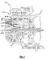
- FIG. 1is a schematic illustration of an automatic transmission with normally engaged disc clutches for a hybrid vehicle
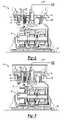
- FIG. 2is an enlarged schematic cross-section of a portion of the automatic transmission of FIG. 1 illustrating a plurality of clutches in an engaged position;
- FIG. 3is an enlarged schematic cross-section of a portion of the automatic transmission of FIGS. 1 and 2 illustrating a plurality of clutches in a disengaged position;
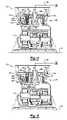
- FIG. 4is an enlarged schematic cross-section of a portion of the automatic transmission of FIG. 1 illustrating another embodiment of a plurality of clutches in an engaged position;
- FIG. 5is an enlarged schematic cross-section of a portion of the automatic transmission of FIGS. 1 and 4 illustrating another embodiment of a plurality of clutches in a disengaged position.
- FIG. 1is a schematic view of an exemplary vehicle 10 , having an automatic transmission 12 .
- the automatic transmission 12includes a plurality of planetary gear sets 14 .
- a plurality of clutches 16 A-Eare located within the transmission 12 to engage and disengage the planetary gear sets 14 from one another and/or from a stationary object, such as a housing 18 of the transmission 12 .
- the number of clutches 16 A-Emay vary according to the arrangement of the transmission 12 in which they are used.
- the transmission 12may include several types and sizes of clutches 16 A-E depending on the function of each specific clutch 16 A-E. One skilled in the art would be able to determine the appropriate number, size and type of clutch for a specific transmission.
- the transmission 12includes a first clutch 16 A and a second clutch 16 B which are normally engaged clutches. That is, the first clutch 16 A and the second clutch 16 B are in an engaged position when at rest and moved to a disengaged position when force is applied to the clutch 16 A, 16 B.
- the first clutch 16 A and the second clutch 16 Bare selected to be normally engaged as the first clutch 16 A and the second clutch 16 B must be engaged when the transmission 12 operates in first gear or in reverse.
- first gear or reverse gearwill be used. Therefore, the first clutch 16 A and the second clutch 16 B will be in an engaged position when the vehicle 10 is starting after a stop.
- FIG. 2illustrates an enlarged schematic view of a cross-section for a portion of the transmission 12 showing the first clutch 16 A and the second clutch 16 B in an engaged position.
- the operation of the first clutch 16 A and the second clutch 16 Bis made with reference to the first clutch 16 A, although both clutches operate in a similar manner.
- the first clutch 16 Aincludes a plurality of clutch plates 20 .
- the plurality of clutch plates 20includes at least one stationary clutch plate 20 A and at least one rotational clutch plate 20 B.
- the stationary clutch plate 20 Ais mounted to an object 21 that is stationary, such as a clutch housing.
- the rotational clutch plate 20 Bis mounted to an object that may rotate when the clutch is in a disengaged position, such as one of the planetary gear sets 14 of the transmission 12
- a backing plate 22is in contact with the plurality of clutch plates 20 .
- a spring 24applies force to the backing plate 22 to engage the backing plate 22 with the plurality of clutch plates 20 .
- the spring 24is a Belleville spring. However, other types of springs may also be used.
- the first clutch 16 Ahas a piston 26 which is fluidly connected to a main transmission pump 28 (shown schematically).
- the main transmission pump 28is the pump that provides pressurized fluid for the clutch input, cooling and lubrication.
- a plurality of fingers 32extend from the piston 26 to the backing plate 22 .
- the plurality of fingers 32extend through apertures 34 in some of the clutch plates 20 .
- the fingers 32are arranged in a concentric ring about an axis 36 of the transmission 12 to evenly apply pressure to the backing plate 22 .
- the main transmission pump 28When a vehicle engine (not shown) is turned on, the main transmission pump 28 is operable.
- the main transmission pump 28applies pressure through a fluid line 38 to the piston 26 .
- FIG. 3illustrates the first clutch 16 A and the second clutch 16 B in a disengaged position.
- the backing plate 22is spaced apart from the clutch plates 20 by a gap 40 of sufficient width to prevent torque transfer through the clutch 120 .
- the spring 24is compressed by the backing plate 22 due to the force applied to the backing plate 22 by the plurality of fingers 32 as a result of fluid pressure acting on the piston 26 .
- a retaining ring 42is located on an opposing side of the spring 24 from the backing plate 22 . The retaining ring 42 secures the spring 24 within the first clutch 16 A and is the grounded reaction member for the force imposed by the spring 24 .
- the spring 24has a spring thickness 44 .
- the spring thickness 44determines the amount of force applied to the backing plate 22 by the spring 24 and the amount of force the piston 26 must apply to disengage the first clutch 16 A. Therefore, the spring thickness 44 may be determined based upon the fluid pressure which is desired to disengage the clutch 16 A for a particular vehicle configuration. One skilled in the art would be able to determine the appropriate fluid pressure and spring thickness 44 for disengagement of the first clutch 16 A.
- FIG. 4illustrates an enlarged schematic view of a cross-section of a portion of a transmission 112 illustrating another embodiment of the present invention.
- the transmission 112includes a first clutch 116 A and a second clutch 116 B illustrated in an engaged position.
- the operation of the first clutch 116 A and the second clutch 116 Bis made with reference to the first clutch 116 A, although both clutches operate in a similar manner.
- the first clutch 116 Aincludes a plurality of clutch plates 120 .
- the plurality of clutch plates 120includes at least one stationary clutch plate 120 A and at least one rotational clutch plate 120 B.
- the stationary clutch plate 120 Ais mounted to an object 121 that is stationary, such as a clutch housing.
- the rotational clutch plate 120 Bis mounted to an object that may rotate when the clutch is in a disengaged position, such as a hub connected to one of the planetary gear sets 114 of the transmission 112
- a first spring 124 A and a second spring 124 Bapply force to the clutch plates 120 to engage the plurality of clutch plates 120 with one another.
- the first spring 124 A and the second spring 124 Bare Belleville springs. However, other types of springs may also be used.
- the first clutch 116 Ahas a piston 126 which is fluidly connected to a main transmission pump 128 (shown schematically).
- a plurality of fingers 132extend from the piston 126 to the second spring 124 B.
- the plurality of fingers 132extend through apertures 134 in some of the clutch plates 120 .
- the fingers 132are arranged in a concentric ring about an axis 136 of the transmission 112 to evenly apply pressure to the second spring 124 B.
- the first spring 124 A and the second spring 124 Bare generally annular in shape and each have an inner edge 146 A, 146 B.
- the first spring 124 A and the second spring 124 Bare in contact with one another at or near the inner edge 146 B of the second spring 124 B.
- the first spring 124 A and the second spring 124 Balso each have an outer edge 148 A, 148 B.
- the outer edge 148 A of the first spring 124 Ais in contact with a clutch housing 150 or a retaining ring 142 .
- the plurality of fingers 32are in contact with the second spring 124 B at or near outer edge 148 B.
- the main transmission pump 128When a vehicle engine (not shown) is turned on, the main transmission pump 128 is operable. The main transmission pump 128 applies pressure through a fluid line 138 to the piston 126 . When the fluid pressure acting on the piston 126 is sufficient to overcome the force applied by the first spring 124 A and the second spring 124 B, the plurality of fingers 132 will compress the first spring 124 A and the second spring 124 B. This will remove the force the first spring 124 A and the second spring 124 B apply to the clutch plates 120 and will disengage the first clutch 116 A.
- FIG. 5illustrates the first clutch 116 A and the second clutch 116 B in a disengaged position.
- the first clutch 116 A and the second clutch 116 Bare illustrated in a disengaged position.
- the first spring 124 A and the second spring 124 Bare compressed by the plurality of fingers 132 as a result of fluid pressure acting on the piston 126 .
- the clutch platesmay or may not have a gap located between one another. However, as the first spring 124 A and the second spring 124 B are not applying force to the clutch plates 120 they may rotate freely and separately from one another and torque will not be transferred through the clutch plates 120 .
- the retaining ring 142is located on an opposing side of the first spring 124 A from the clutch plates 120 .
- the retaining ring 142secures the first spring 124 A and the second spring 124 B within the first clutch 116 A and is the grounding reaction member for the forces imposed by the first spring 124 A and the second spring 124 B.
- the first spring 124 A and the second spring 124 Beach have a spring thickness 144 .
- the spring thickness 144is preferably the same or nearly the same for the first spring 124 A and the second spring 124 B so that the first spring 124 A and the second spring 124 B both compress a comparable amount to one another.
- the spring thickness 144determines the amount of force applied to the clutch plates 120 by the first spring 124 A and the second spring 124 B and the amount of force the piston 126 must apply to disengage the first clutch 116 A. Therefore, the spring thickness 144 may be determined based upon the fluid pressure which is desired to disengage the clutch for a particular vehicle configuration. One skilled in the art would be able to determine the appropriate fluid pressure and spring thickness 144 for disengagement of the first clutch 116 A.
Landscapes
- Engineering & Computer Science (AREA)
- General Engineering & Computer Science (AREA)
- Mechanical Engineering (AREA)
- Hydraulic Clutches, Magnetic Clutches, Fluid Clutches, And Fluid Joints (AREA)
Abstract
Description
Claims (5)
Priority Applications (3)
| Application Number | Priority Date | Filing Date | Title |
|---|---|---|---|
| US12/420,993US8201678B2 (en) | 2009-04-09 | 2009-04-09 | Automatic transmission with normally engaged disc clutches |
| DE102010012705ADE102010012705A1 (en) | 2009-04-09 | 2010-03-25 | Automatic transmission with normally engaged disc clutches |
| CN2010101627587ACN101858422B (en) | 2009-04-09 | 2010-04-09 | Automatic transmission with normally engaged disc clutches |
Applications Claiming Priority (1)
| Application Number | Priority Date | Filing Date | Title |
|---|---|---|---|
| US12/420,993US8201678B2 (en) | 2009-04-09 | 2009-04-09 | Automatic transmission with normally engaged disc clutches |
Publications (2)
| Publication Number | Publication Date |
|---|---|
| US20100261574A1 US20100261574A1 (en) | 2010-10-14 |
| US8201678B2true US8201678B2 (en) | 2012-06-19 |
Family
ID=42934848
Family Applications (1)
| Application Number | Title | Priority Date | Filing Date |
|---|---|---|---|
| US12/420,993Expired - Fee RelatedUS8201678B2 (en) | 2009-04-09 | 2009-04-09 | Automatic transmission with normally engaged disc clutches |
Country Status (3)
| Country | Link |
|---|---|
| US (1) | US8201678B2 (en) |
| CN (1) | CN101858422B (en) |
| DE (1) | DE102010012705A1 (en) |
Cited By (1)
| Publication number | Priority date | Publication date | Assignee | Title |
|---|---|---|---|---|
| US20120168238A1 (en)* | 2011-01-05 | 2012-07-05 | Gm Global Technology Operations, Inc. | Method and apparatus for hydraulically deactivating a torque transfer clutch |
Families Citing this family (6)
| Publication number | Priority date | Publication date | Assignee | Title |
|---|---|---|---|---|
| DE102008063905B4 (en)* | 2008-12-19 | 2013-10-24 | Gkn Driveline International Gmbh | Drive arrangement with hydraulic actuation |
| EP2531365A4 (en)* | 2010-02-05 | 2015-08-12 | Nt Consulting Int Pty Ltd | Electric vehicle transmission |
| US9347502B2 (en)* | 2013-12-23 | 2016-05-24 | Gm Global Technology Operations, Llc | Transmission having a strap spring hub |
| DE102014220136A1 (en)* | 2014-10-06 | 2016-04-07 | Zf Friedrichshafen Ag | Double coupling |
| CN207128609U (en) | 2016-12-23 | 2018-03-23 | 舍弗勒技术股份两合公司 | Hybrid module and drive assembly for a motor vehicle |
| KR102292261B1 (en)* | 2020-02-04 | 2021-08-20 | 주식회사 카펙발레오 | Hybrid drive module |
Citations (10)
| Publication number | Priority date | Publication date | Assignee | Title |
|---|---|---|---|---|
| US4440279A (en)* | 1980-08-29 | 1984-04-03 | Zahnradfabrik Friedrichshafen Ag | Control system or method for a friction device such as a clutch or brake |
| US4775041A (en)* | 1985-12-16 | 1988-10-04 | Baruffaldi Frizioni S.P.A. | Compact friction clutch with actuated disengagement, suitable for vehicle compressors |
| US5232411A (en)* | 1991-07-26 | 1993-08-03 | Nissan Motor Co., Ltd. | Structure for automatic transmission |
| US5511644A (en)* | 1993-08-24 | 1996-04-30 | Toyota Jidosha Kabushiki Kaisha | Frictional engagement device for an automatic transmission |
| US5538121A (en)* | 1992-11-03 | 1996-07-23 | Deere & Company | Pressure actuated multi-disk clutch |
| US5743369A (en)* | 1994-12-24 | 1998-04-28 | Massey-Ferguson S.A. | Wet clutch assembly |
| US5913397A (en)* | 1996-09-05 | 1999-06-22 | Jatco Corporation | Clutch structure with piston having surface recessed from pressure surface for reducing stress concentration |
| US6360623B1 (en)* | 1999-06-14 | 2002-03-26 | Kanzaki Kokyukoki Mfg. Co., Ltd. | Transmission system in working vehicles |
| US6786317B2 (en)* | 2001-09-04 | 2004-09-07 | Kanzaki Kokyukoki Mfg. Co. Ltd. | Hydraulic clutch assembly |
| US7036645B2 (en)* | 2004-06-18 | 2006-05-02 | General Motors Corporation | Rotating torque-transmitting apparatus |
Family Cites Families (1)
| Publication number | Priority date | Publication date | Assignee | Title |
|---|---|---|---|---|
| KR20050029508A (en)* | 2003-09-23 | 2005-03-28 | 현대자동차주식회사 | Multiple disc clutch of auto transmission |
- 2009
- 2009-04-09USUS12/420,993patent/US8201678B2/ennot_activeExpired - Fee Related
- 2010
- 2010-03-25DEDE102010012705Apatent/DE102010012705A1/ennot_activeWithdrawn
- 2010-04-09CNCN2010101627587Apatent/CN101858422B/ennot_activeExpired - Fee Related
Patent Citations (10)
| Publication number | Priority date | Publication date | Assignee | Title |
|---|---|---|---|---|
| US4440279A (en)* | 1980-08-29 | 1984-04-03 | Zahnradfabrik Friedrichshafen Ag | Control system or method for a friction device such as a clutch or brake |
| US4775041A (en)* | 1985-12-16 | 1988-10-04 | Baruffaldi Frizioni S.P.A. | Compact friction clutch with actuated disengagement, suitable for vehicle compressors |
| US5232411A (en)* | 1991-07-26 | 1993-08-03 | Nissan Motor Co., Ltd. | Structure for automatic transmission |
| US5538121A (en)* | 1992-11-03 | 1996-07-23 | Deere & Company | Pressure actuated multi-disk clutch |
| US5511644A (en)* | 1993-08-24 | 1996-04-30 | Toyota Jidosha Kabushiki Kaisha | Frictional engagement device for an automatic transmission |
| US5743369A (en)* | 1994-12-24 | 1998-04-28 | Massey-Ferguson S.A. | Wet clutch assembly |
| US5913397A (en)* | 1996-09-05 | 1999-06-22 | Jatco Corporation | Clutch structure with piston having surface recessed from pressure surface for reducing stress concentration |
| US6360623B1 (en)* | 1999-06-14 | 2002-03-26 | Kanzaki Kokyukoki Mfg. Co., Ltd. | Transmission system in working vehicles |
| US6786317B2 (en)* | 2001-09-04 | 2004-09-07 | Kanzaki Kokyukoki Mfg. Co. Ltd. | Hydraulic clutch assembly |
| US7036645B2 (en)* | 2004-06-18 | 2006-05-02 | General Motors Corporation | Rotating torque-transmitting apparatus |
Cited By (2)
| Publication number | Priority date | Publication date | Assignee | Title |
|---|---|---|---|---|
| US20120168238A1 (en)* | 2011-01-05 | 2012-07-05 | Gm Global Technology Operations, Inc. | Method and apparatus for hydraulically deactivating a torque transfer clutch |
| US8545354B2 (en)* | 2011-01-05 | 2013-10-01 | GM Global Technology Operations LLC | Method and apparatus for hydraulically deactivating a torque transfer clutch |
Also Published As
| Publication number | Publication date |
|---|---|
| CN101858422A (en) | 2010-10-13 |
| CN101858422B (en) | 2013-06-19 |
| DE102010012705A1 (en) | 2010-11-18 |
| US20100261574A1 (en) | 2010-10-14 |
Similar Documents
| Publication | Publication Date | Title |
|---|---|---|
| US8201678B2 (en) | Automatic transmission with normally engaged disc clutches | |
| CN108138859B (en) | Friction clutch with rotary axis | |
| US20070175725A1 (en) | Multiplate wet clutch | |
| CN102734344A (en) | Multi-disc frictional engagement mechanism | |
| US20080029332A1 (en) | Multiplate clutch and motor vehicle having the same | |
| EP0640773A1 (en) | Frictional engagement device for an automatic transmission | |
| US7527135B2 (en) | Multiplate friction clutch | |
| US7137498B2 (en) | Centrifugal clutch with improved wear life and disengagement characteristics | |
| EP1918602A2 (en) | Clutch assembly with bleed assembly for centrifugal pressure | |
| CN108105278B (en) | Wet clutch assembly | |
| US6892869B2 (en) | Multi-plate friction clutch | |
| US11073181B2 (en) | Transmission and method for shifting a transmission | |
| US8210979B2 (en) | Dual-piston normally-engaged clutch | |
| US10760621B2 (en) | Clutching device of an automatic transmission | |
| KR101155649B1 (en) | Friction element | |
| CN210715642U (en) | Clutch device, gearbox and electric automobile | |
| CN110454515A (en) | A clutch device, gearbox and electric vehicle | |
| KR101155648B1 (en) | Friction element | |
| KR20110090582A (en) | Friction element | |
| US11585419B1 (en) | Constant-on double coast engagement diaphragm spring | |
| US7237661B2 (en) | Integral input shaft brake and disconnect apparatus | |
| US20070221466A1 (en) | Clutch actuation method and apparatus | |
| KR101085441B1 (en) | Clutch for Automatic Transmission | |
| KR101495821B1 (en) | Brake | |
| KR102540878B1 (en) | Clutch-brake device |
Legal Events
| Date | Code | Title | Description |
|---|---|---|---|
| AS | Assignment | Owner name:GM GLOBAL TECHNOLOGY OPERATIONS, INC., MICHIGAN Free format text:ASSIGNMENT OF ASSIGNORS INTEREST;ASSIGNORS:SAMIE, FARZAD;JONES, GARY L.;BARTOS, ANDREW L.;SIGNING DATES FROM 20090406 TO 20090407;REEL/FRAME:022525/0794 | |
| AS | Assignment | Owner name:UNITED STATES DEPARTMENT OF THE TREASURY, DISTRICT Free format text:SECURITY AGREEMENT;ASSIGNOR:GM GLOBAL TECHNOLOGY OPERATIONS, INC.;REEL/FRAME:023201/0118 Effective date:20090710 | |
| AS | Assignment | Owner name:UAW RETIREE MEDICAL BENEFITS TRUST, MICHIGAN Free format text:SECURITY AGREEMENT;ASSIGNOR:GM GLOBAL TECHNOLOGY OPERATIONS, INC.;REEL/FRAME:023162/0048 Effective date:20090710 | |
| AS | Assignment | Owner name:GM GLOBAL TECHNOLOGY OPERATIONS, INC., MICHIGAN Free format text:RELEASE BY SECURED PARTY;ASSIGNOR:UNITED STATES DEPARTMENT OF THE TREASURY;REEL/FRAME:025246/0056 Effective date:20100420 | |
| AS | Assignment | Owner name:GM GLOBAL TECHNOLOGY OPERATIONS, INC., MICHIGAN Free format text:RELEASE BY SECURED PARTY;ASSIGNOR:UAW RETIREE MEDICAL BENEFITS TRUST;REEL/FRAME:025315/0091 Effective date:20101026 | |
| AS | Assignment | Owner name:WILMINGTON TRUST COMPANY, DELAWARE Free format text:SECURITY AGREEMENT;ASSIGNOR:GM GLOBAL TECHNOLOGY OPERATIONS, INC.;REEL/FRAME:025324/0555 Effective date:20101027 | |
| AS | Assignment | Owner name:GM GLOBAL TECHNOLOGY OPERATIONS LLC, MICHIGAN Free format text:CHANGE OF NAME;ASSIGNOR:GM GLOBAL TECHNOLOGY OPERATIONS, INC.;REEL/FRAME:025781/0245 Effective date:20101202 | |
| FEPP | Fee payment procedure | Free format text:PAYOR NUMBER ASSIGNED (ORIGINAL EVENT CODE: ASPN); ENTITY STATUS OF PATENT OWNER: LARGE ENTITY | |
| STCF | Information on status: patent grant | Free format text:PATENTED CASE | |
| AS | Assignment | Owner name:GM GLOBAL TECHNOLOGY OPERATIONS LLC, MICHIGAN Free format text:RELEASE BY SECURED PARTY;ASSIGNOR:WILMINGTON TRUST COMPANY;REEL/FRAME:034185/0789 Effective date:20141017 | |
| FPAY | Fee payment | Year of fee payment:4 | |
| FEPP | Fee payment procedure | Free format text:MAINTENANCE FEE REMINDER MAILED (ORIGINAL EVENT CODE: REM.); ENTITY STATUS OF PATENT OWNER: LARGE ENTITY | |
| LAPS | Lapse for failure to pay maintenance fees | Free format text:PATENT EXPIRED FOR FAILURE TO PAY MAINTENANCE FEES (ORIGINAL EVENT CODE: EXP.); ENTITY STATUS OF PATENT OWNER: LARGE ENTITY | |
| STCH | Information on status: patent discontinuation | Free format text:PATENT EXPIRED DUE TO NONPAYMENT OF MAINTENANCE FEES UNDER 37 CFR 1.362 | |
| FP | Lapsed due to failure to pay maintenance fee | Effective date:20200619 |