US8201563B2 - Method for introducing materials into a body - Google Patents
Method for introducing materials into a bodyDownload PDFInfo
- Publication number
- US8201563B2 US8201563B2US11/368,508US36850806AUS8201563B2US 8201563 B2US8201563 B2US 8201563B2US 36850806 AUS36850806 AUS 36850806AUS 8201563 B2US8201563 B2US 8201563B2
- Authority
- US
- United States
- Prior art keywords
- elongate member
- tissue
- cannula
- distal end
- lumen
- Prior art date
- Legal status (The legal status is an assumption and is not a legal conclusion. Google has not performed a legal analysis and makes no representation as to the accuracy of the status listed.)
- Active, expires
Links
- 239000000463materialSubstances0.000titleclaimsabstractdescription83
- 238000000034methodMethods0.000titleclaimsabstractdescription72
- 230000006870functionEffects0.000claimsdescription8
- 239000012530fluidSubstances0.000claimsdescription7
- 238000012800visualizationMethods0.000claimsdescription4
- 239000003242anti bacterial agentSubstances0.000claimsdescription3
- 230000003115biocidal effectEffects0.000claimsdescription3
- 239000004568cementSubstances0.000claimsdescription3
- 230000003444anaesthetic effectEffects0.000claimsdescription2
- 230000003068static effectEffects0.000claimsdescription2
- 210000001519tissueAnatomy0.000description191
- 206010016654FibrosisDiseases0.000description16
- 230000004761fibrosisEffects0.000description16
- 239000003550markerSubstances0.000description12
- 239000000523sampleSubstances0.000description9
- 238000003780insertionMethods0.000description5
- 238000005304joiningMethods0.000description5
- -1polyethylenesPolymers0.000description5
- 239000000126substanceSubstances0.000description5
- 230000009286beneficial effectEffects0.000description4
- 230000037431insertionEffects0.000description4
- 230000007246mechanismEffects0.000description4
- 229910001000nickel titaniumInorganic materials0.000description4
- 239000004033plasticSubstances0.000description4
- 229920003023plasticPolymers0.000description4
- 229910001220stainless steelInorganic materials0.000description4
- 206010028980NeoplasmDiseases0.000description3
- HZEWFHLRYVTOIW-UHFFFAOYSA-N[Ti].[Ni]Chemical compound[Ti].[Ni]HZEWFHLRYVTOIW-UHFFFAOYSA-N0.000description3
- 230000003213activating effectEffects0.000description3
- 230000004913activationEffects0.000description3
- 239000000853adhesiveSubstances0.000description3
- 230000001070adhesive effectEffects0.000description3
- 229910045601alloyInorganic materials0.000description3
- 239000000956alloySubstances0.000description3
- 238000004458analytical methodMethods0.000description3
- 210000000988bone and boneAnatomy0.000description3
- 238000002594fluoroscopyMethods0.000description3
- 239000007788liquidSubstances0.000description3
- 238000004519manufacturing processMethods0.000description3
- 238000002360preparation methodMethods0.000description3
- 230000008569processEffects0.000description3
- 239000000243solutionSubstances0.000description3
- 102000008186CollagenHuman genes0.000description2
- 108010035532CollagenProteins0.000description2
- 239000004698PolyethyleneSubstances0.000description2
- 239000004642PolyimideSubstances0.000description2
- 238000013459approachMethods0.000description2
- 210000001185bone marrowAnatomy0.000description2
- 230000008859changeEffects0.000description2
- 229920001436collagenPolymers0.000description2
- 229920001577copolymerPolymers0.000description2
- 238000003384imaging methodMethods0.000description2
- 238000002847impedance measurementMethods0.000description2
- 238000002347injectionMethods0.000description2
- 239000007924injectionSubstances0.000description2
- 238000012986modificationMethods0.000description2
- 230000004048modificationEffects0.000description2
- 238000012806monitoring deviceMethods0.000description2
- 229920001778nylonPolymers0.000description2
- 230000003287optical effectEffects0.000description2
- 229920000728polyesterPolymers0.000description2
- 229920000573polyethylenePolymers0.000description2
- 229920001721polyimidePolymers0.000description2
- 229920002635polyurethanePolymers0.000description2
- 239000004814polyurethaneSubstances0.000description2
- 238000007789sealingMethods0.000description2
- 239000012781shape memory materialSubstances0.000description2
- 238000002604ultrasonographyMethods0.000description2
- 238000003466weldingMethods0.000description2
- 208000035143Bacterial infectionDiseases0.000description1
- 208000026310Breast neoplasmDiseases0.000description1
- 206010011732CystDiseases0.000description1
- 206010061968Gastric neoplasmDiseases0.000description1
- 206010019695Hepatic neoplasmDiseases0.000description1
- 208000003618Intervertebral Disc DisplacementDiseases0.000description1
- 206010050296Intervertebral disc protrusionDiseases0.000description1
- WHXSMMKQMYFTQS-UHFFFAOYSA-NLithiumChemical compound[Li]WHXSMMKQMYFTQS-UHFFFAOYSA-N0.000description1
- 239000004743PolypropyleneSubstances0.000description1
- 102000029797PrionHuman genes0.000description1
- 108091000054PrionProteins0.000description1
- 239000004809TeflonSubstances0.000description1
- 229920006362Teflon®Polymers0.000description1
- 241000700605VirusesSpecies0.000description1
- 210000000577adipose tissueAnatomy0.000description1
- 230000000202analgesic effectEffects0.000description1
- 238000004873anchoringMethods0.000description1
- 230000003143atherosclerotic effectEffects0.000description1
- 208000022362bacterial infectious diseaseDiseases0.000description1
- 230000008901benefitEffects0.000description1
- 239000008280bloodSubstances0.000description1
- 210000004369bloodAnatomy0.000description1
- 238000009534blood testMethods0.000description1
- 238000009529body temperature measurementMethods0.000description1
- 210000000481breastAnatomy0.000description1
- OJIJEKBXJYRIBZ-UHFFFAOYSA-Ncadmium nickelChemical compound[Ni].[Cd]OJIJEKBXJYRIBZ-UHFFFAOYSA-N0.000description1
- 210000000845cartilageAnatomy0.000description1
- 239000011248coating agentSubstances0.000description1
- 238000000576coating methodMethods0.000description1
- 210000001072colonAnatomy0.000description1
- 208000029742colonic neoplasmDiseases0.000description1
- 150000001875compoundsChemical class0.000description1
- 238000002591computed tomographyMethods0.000description1
- 238000010276constructionMethods0.000description1
- 238000002788crimpingMethods0.000description1
- 208000031513cystDiseases0.000description1
- 238000002059diagnostic imagingMethods0.000description1
- 238000002405diagnostic procedureMethods0.000description1
- 230000000694effectsEffects0.000description1
- 239000002657fibrous materialSubstances0.000description1
- 238000007429general methodMethods0.000description1
- 230000036541healthEffects0.000description1
- 238000010438heat treatmentMethods0.000description1
- 238000010348incorporationMethods0.000description1
- 208000015181infectious diseaseDiseases0.000description1
- 208000014674injuryDiseases0.000description1
- 229910052744lithiumInorganic materials0.000description1
- 208000014018liver neoplasmDiseases0.000description1
- 230000003211malignant effectEffects0.000description1
- 230000010534mechanism of actionEffects0.000description1
- 229910052751metalInorganic materials0.000description1
- 239000002184metalSubstances0.000description1
- 239000002991molded plasticSubstances0.000description1
- 238000012544monitoring processMethods0.000description1
- HLXZNVUGXRDIFK-UHFFFAOYSA-Nnickel titaniumChemical compound[Ti].[Ti].[Ti].[Ti].[Ti].[Ti].[Ti].[Ti].[Ti].[Ti].[Ti].[Ni].[Ni].[Ni].[Ni].[Ni].[Ni].[Ni].[Ni].[Ni].[Ni].[Ni].[Ni].[Ni].[Ni]HLXZNVUGXRDIFK-UHFFFAOYSA-N0.000description1
- ORQBXQOJMQIAOY-UHFFFAOYSA-NnobeliumChemical compound[No]ORQBXQOJMQIAOY-UHFFFAOYSA-N0.000description1
- 238000002355open surgical procedureMethods0.000description1
- 230000007170pathologyEffects0.000description1
- 230000000149penetrating effectEffects0.000description1
- 230000000704physical effectEffects0.000description1
- 239000006223plastic coatingSubstances0.000description1
- 229920000052poly(p-xylylene)Polymers0.000description1
- 229920000515polycarbonatePolymers0.000description1
- 239000004417polycarbonateSubstances0.000description1
- 229920000642polymerPolymers0.000description1
- 229920001155polypropylenePolymers0.000description1
- 229920001343polytetrafluoroethylenePolymers0.000description1
- 239000004810polytetrafluoroethyleneSubstances0.000description1
- 229920000915polyvinyl chloridePolymers0.000description1
- 239000004800polyvinyl chlorideSubstances0.000description1
- 238000011084recoveryMethods0.000description1
- 238000009877renderingMethods0.000description1
- 239000004576sandSubstances0.000description1
- 238000007790scrapingMethods0.000description1
- 230000035807sensationEffects0.000description1
- 238000000926separation methodMethods0.000description1
- 210000004872soft tissueAnatomy0.000description1
- 238000005476solderingMethods0.000description1
- 210000001032spinal nerveAnatomy0.000description1
- 239000010935stainless steelSubstances0.000description1
- 230000001954sterilising effectEffects0.000description1
- 238000004659sterilization and disinfectionMethods0.000description1
- 210000002784stomachAnatomy0.000description1
- 238000001356surgical procedureMethods0.000description1
- 230000008733traumaEffects0.000description1
- 239000011345viscous materialSubstances0.000description1
- 239000002676xenobiotic agentSubstances0.000description1
- 230000002034xenobiotic effectEffects0.000description1
Images


Classifications
- A—HUMAN NECESSITIES
- A61—MEDICAL OR VETERINARY SCIENCE; HYGIENE
- A61B—DIAGNOSIS; SURGERY; IDENTIFICATION
- A61B17/00—Surgical instruments, devices or methods
- A61B17/32—Surgical cutting instruments
- A61B17/3205—Excision instruments
- A61B17/3207—Atherectomy devices working by cutting or abrading; Similar devices specially adapted for non-vascular obstructions
- A61B17/320758—Atherectomy devices working by cutting or abrading; Similar devices specially adapted for non-vascular obstructions with a rotating cutting instrument, e.g. motor driven
- A—HUMAN NECESSITIES
- A61—MEDICAL OR VETERINARY SCIENCE; HYGIENE
- A61B—DIAGNOSIS; SURGERY; IDENTIFICATION
- A61B17/00—Surgical instruments, devices or methods
- A61B17/32—Surgical cutting instruments
- A61B17/320016—Endoscopic cutting instruments, e.g. arthroscopes, resectoscopes
- A—HUMAN NECESSITIES
- A61—MEDICAL OR VETERINARY SCIENCE; HYGIENE
- A61B—DIAGNOSIS; SURGERY; IDENTIFICATION
- A61B18/00—Surgical instruments, devices or methods for transferring non-mechanical forms of energy to or from the body
- A61B18/04—Surgical instruments, devices or methods for transferring non-mechanical forms of energy to or from the body by heating
- A61B18/12—Surgical instruments, devices or methods for transferring non-mechanical forms of energy to or from the body by heating by passing a current through the tissue to be heated, e.g. high-frequency current
- A61B18/14—Probes or electrodes therefor
- A61B18/148—Probes or electrodes therefor having a short, rigid shaft for accessing the inner body transcutaneously, e.g. for neurosurgery or arthroscopy
- A—HUMAN NECESSITIES
- A61—MEDICAL OR VETERINARY SCIENCE; HYGIENE
- A61B—DIAGNOSIS; SURGERY; IDENTIFICATION
- A61B17/00—Surgical instruments, devices or methods
- A61B17/32—Surgical cutting instruments
- A61B17/320016—Endoscopic cutting instruments, e.g. arthroscopes, resectoscopes
- A61B17/32002—Endoscopic cutting instruments, e.g. arthroscopes, resectoscopes with continuously rotating, oscillating or reciprocating cutting instruments
- A—HUMAN NECESSITIES
- A61—MEDICAL OR VETERINARY SCIENCE; HYGIENE
- A61B—DIAGNOSIS; SURGERY; IDENTIFICATION
- A61B17/00—Surgical instruments, devices or methods
- A61B17/00234—Surgical instruments, devices or methods for minimally invasive surgery
- A61B2017/00238—Type of minimally invasive operation
- A61B2017/00261—Discectomy
- A—HUMAN NECESSITIES
- A61—MEDICAL OR VETERINARY SCIENCE; HYGIENE
- A61B—DIAGNOSIS; SURGERY; IDENTIFICATION
- A61B17/00—Surgical instruments, devices or methods
- A61B2017/00681—Aspects not otherwise provided for
- A61B2017/00685—Archimedes screw
- A—HUMAN NECESSITIES
- A61—MEDICAL OR VETERINARY SCIENCE; HYGIENE
- A61B—DIAGNOSIS; SURGERY; IDENTIFICATION
- A61B17/00—Surgical instruments, devices or methods
- A61B17/32—Surgical cutting instruments
- A61B17/3205—Excision instruments
- A61B17/3207—Atherectomy devices working by cutting or abrading; Similar devices specially adapted for non-vascular obstructions
- A61B17/320758—Atherectomy devices working by cutting or abrading; Similar devices specially adapted for non-vascular obstructions with a rotating cutting instrument, e.g. motor driven
- A61B2017/320775—Morcellators, impeller or propeller like means
- A—HUMAN NECESSITIES
- A61—MEDICAL OR VETERINARY SCIENCE; HYGIENE
- A61B—DIAGNOSIS; SURGERY; IDENTIFICATION
- A61B18/00—Surgical instruments, devices or methods for transferring non-mechanical forms of energy to or from the body
- A61B2018/00315—Surgical instruments, devices or methods for transferring non-mechanical forms of energy to or from the body for treatment of particular body parts
- A61B2018/00434—Neural system
- A61B2018/0044—Spinal cord
- A—HUMAN NECESSITIES
- A61—MEDICAL OR VETERINARY SCIENCE; HYGIENE
- A61B—DIAGNOSIS; SURGERY; IDENTIFICATION
- A61B90/00—Instruments, implements or accessories specially adapted for surgery or diagnosis and not covered by any of the groups A61B1/00 - A61B50/00, e.g. for luxation treatment or for protecting wound edges
- A61B90/03—Automatic limiting or abutting means, e.g. for safety
- A61B2090/032—Automatic limiting or abutting means, e.g. for safety pressure limiting, e.g. hydrostatic
- A—HUMAN NECESSITIES
- A61—MEDICAL OR VETERINARY SCIENCE; HYGIENE
- A61B—DIAGNOSIS; SURGERY; IDENTIFICATION
- A61B90/00—Instruments, implements or accessories specially adapted for surgery or diagnosis and not covered by any of the groups A61B1/00 - A61B50/00, e.g. for luxation treatment or for protecting wound edges
- A61B90/06—Measuring instruments not otherwise provided for
- A61B2090/064—Measuring instruments not otherwise provided for for measuring force, pressure or mechanical tension
- A61B2090/065—Measuring instruments not otherwise provided for for measuring force, pressure or mechanical tension for measuring contact or contact pressure
- A—HUMAN NECESSITIES
- A61—MEDICAL OR VETERINARY SCIENCE; HYGIENE
- A61B—DIAGNOSIS; SURGERY; IDENTIFICATION
- A61B90/00—Instruments, implements or accessories specially adapted for surgery or diagnosis and not covered by any of the groups A61B1/00 - A61B50/00, e.g. for luxation treatment or for protecting wound edges
- A61B90/06—Measuring instruments not otherwise provided for
Definitions
- the inventionrelates to methods for introduction of materials into a patient's body. More particularly, the invention relates to such methods that are minimally invasive.
- syringesare commonly used to inject fluids into a patient. Syringes however, may not be suitable for more viscous or fibrous materials, such as collagen. Furthermore, when the procedure requires that material be removed from the body in addition to the introduction of exogenous material, a syringe may not be suitable.
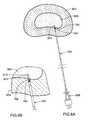
- FIG. 1Ais a perspective view of one embodiment of the device of the invention.
- FIG. 1Bis a side-view of one embodiment of the device of the invention.
- FIG. 1Cis a top-view of one embodiment of the device of the invention.
- FIGS. 2A-Dare perspective views of several embodiments of the distal portion of the elongate member.
- FIG. 3is a sectional view of the distal portion of one embodiment of the apparatus.
- FIGS. 4A-Eare perspective views of several embodiments of the slits of the apparatus.
- FIG. 5is a sectional view of one embodiment of the apparatus.
- FIG. 6is a sectional view of one embodiment of one portion of the apparatus.
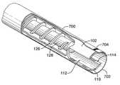
- FIG. 7is a cutaway view of the distal portion of one embodiment of the distal portion of the apparatus.
- FIGS. 8A-8Lare illustrations of one embodiment of an application of the method of the invention.
- the term “at”, for example when referring to something being located “at” a specific location,is intended to include any one or more of: proximate, on, near, adjacent to or within the specific location.
- distal and proximalare defined with respect to the user. In other words, the term “distal” refers to the part or portion further away from the user, while the term “proximal” refers to the part or portion closer to the user.
- the “posterior portion” of the nucleus pulposusrefers to the approximately half of the nucleus pulposus that is closest to the dorsal side of the body, and the “anterior portion” of the nucleus pulposus refers to the approximately half of the nucleus pulposus that is closest to the ventral side of the body.
- shaftrefers to an elongate element having either a closed or open distal end.
- the term “bent”refers to any deviation from a longitudinal axis.
- slotrefers to an outcutting, slit, gap, or hole and is not limited in size or shape.
- obturatorrefers to any item that substantially fills or blocks a lumen.
- cannulais defined as an elongate device defining a lumen.
- coringrefers to advancing an elongate member defining a lumen and having an open distal end into a tissue, wherein the advancement results in the incorporation or gathering of at least a portion of the tissue into the lumen of the elongate member.
- operatively connectedis intended to mean “coupled or connected, either directly or indirectly, such that the connected structures are operable to perform a desired function”.
- the term “conveyance”refers to facilitation of movement of a material from one location to another.
- the term “fully disposed”refers to a first member being substantially fully received within a second member such that, under normal use, it is not intended to be inserted into the other member any further.
- the present inventioncomprises an apparatus for removal of materials from the body of a patient.
- the apparatusis used for removal of nucleus pulposus tissue from an intervertebral disc.
- the apparatusmay generally comprise a tissue removal member housed at least partially within an elongate member defining a lumen, for example a sheath.
- the tissue removal membermay be any device that functions to convey tissue from the distal end of the elongate member to a portion exterior to the patient's body.
- the tissue removal memberis a shaft with at least one projection extending outwardly from the shaft.
- the shaftmay have a plurality of projections extending outwardly therefrom.
- the tissue removal memberis operatively connected to a motor or other source of rotational energy which provides the motion required to remove the tissue.
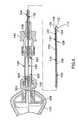
- the apparatuscomprises an elongate member 102 , a handpiece 140 , and a receptacle 138 for collection or visualization of tissue.
- elongate member 102comprises proximal portion 104 ending in open proximal end 106 , and distal portion 108 ending in open distal end 110 .
- proximal end 106may be closed and proximal portion 104 may define one or more apertures in a lateral wall thereof.
- Open distal end 110defines aperture 112 .
- the cross-sectional shape of elongate member 102is substantially circular, however alternate embodiments are possible, wherein the shape may be ovoid, square, or rectangular, and elongate member 102 is not limited in this regard.
- aperture 112may be substantially perpendicular to the longitudinal axis of elongate member 102 ; however distal end 110 of elongate member 102 may be beveled or otherwise oriented, in which case the plane of aperture 112 would not necessarily be perpendicular to the longitudinal axis of the shaft.
- elongate member 102is sized to be percutaneously directed to an interior tissue of the body.
- the length of elongate member 102is generally between about 15.0 and about 25.0 cm, more specifically between about 17.0 and about 19.0 cm; however it may be otherwise sized to reach any target tissue within the body.
- the diameter of elongate member 102is generally between about 0.5 and about 5.0 mm, more specifically between about 1.0 and about 2.0 mm, however it may be otherwise sized to fit within the space defined by the target tissue.
- elongate member 102may be bent or curved, as shown in FIGS. 2A-2D . This may allow for easier access to a target site.
- the bend or curvemay be applied by the user prior to or during the procedure, or may be applied during manufacture. Many angles are possible depending on the nature of the target tissue. For example, if the target tissue is the nucleus pulposus of an intervertebral disc, the curve may be at such an angle that the posterior portion of the nucleus pulposus may be reached with the device while allowing for an approach that reduces risk of damage to the spinal canal. In this example, the angle of curvature would generally be between about 1.0 and about 5.0°.
- Distal end 110 of elongate member 102may additionally comprise a variety of geometries such as blunt, sharp, beveled, crown-shaped, fishhook shaped, or any other shape that will not interfere with the proper functioning of apparatus 100 .
- Elongate member 102may be manufactured from a number of different materials. These include, but are not limited to, stainless steels, shape-memory materials such as nickel titanium alloys, polyesters, polyethylenes, polyurethanes, polyimides, nylons, copolymers thereof, and medical grade plastics. In one specific embodiment, elongate member 102 is made from a clear, transparent or translucent plastic or other material. This embodiment may allow the user to visualize the contents of elongate member 102 to ensure that it is operating properly.
- elongate member 102is structured to define at least one slot in distal portion 108 .
- the at least one slot 114may function to allow more tissue to enter elongate member 102 , and may allow for ease of movement through the target tissue, while still maintaining the separation of the non-target tissues from tissue removal member 116 .
- slot(s) 114may extend proximally from distal end 110 of elongate member 102 .
- Slot(s) 114may extend to a point on elongate member 102 that is substantially coplanar with distal end 136 of shaft 128 when shaft 128 is fully inserted into sheath 102 .
- slot(s) 114may extend to a point that is either proximal or distal to distal end 136 of shaft 128 .
- slot(s) 114may be between about 0.5 mm and about 3 mm in length.
- slot(s) 114may be defined in a variety of shapes including rectangular, square, triangular, or any other shape that would not interfere with the proper functioning of apparatus 100 .
- the slotsmay be circumferentially arranged in any manner that will not interfere with the proper functioning apparatus 100 .
- elongate member 102may include 2 slots that are diametrically opposite each other, or substantially adjacent to each other.
- elongate member 102may include 3 slots that are equidistant from each other, or that are all arranged on one hemisphere of the distal end of the elongate member.
- different arrangements and shapes of slotsmay be included.
- the shape, positioning, or size of each of the slotsneed not be identical.
- Slot(s) 114may be created in a number of ways. For example, a Dremel or other rotary tool may be used to cut or sand slot 114 into elongate member 102 . Alternatively, sheath 102 may be manufactured with slots 114 included.
- apparatus 100comprises tissue removal member 116 , which is structured to be disposed within elongate member 102 .
- Tissue removal member 116comprises a proximal portion ending in a proximal end, and distal portion 122 ending in distal end 124 .
- tissue removal member 116may be coaxial with elongate member 102 ; however tissue removal member 116 may be otherwise aligned.
- the length of tissue removal member 116is such that the proximal portion of tissue removal member 116 extends proximally beyond proximal end 106 of elongate member 102 ; however proximal ends of elongate member 102 and tissue removal member 116 may be flush or otherwise aligned.
- distal end 124 of tissue removal member 116is recessed proximally from the distal end of elongate member 102 . This structure allows for distal portion 122 of tissue removal member 116 to be substantially shrouded within elongate member 102 . This arrangement may protect surrounding tissues from being damaged by contact with tissue removal member 116 .
- tissue removal member 116is recessed from distal end 110 of elongate member 102 is generally between about 0.5 and about 4.0 mm, more specifically between about 0.5 and about 2.0 mm; however, in this embodiment, the distance may be any amount such that tissue removal member 116 does not contact tissue until after the tissue has already entered elongate member 102 . Further details regarding the recession of tissue removal member 116 are discussed hereinbelow.
- tissue removal member 116comprises a shaft 128 having outwardly extending projections 126 .
- the outwardly extending projectionsmay comprise a helical flighting or helical element disposed at least partially around shaft 128 .
- This arrangementmay functionally form an auger, wherein the term auger, refers to a device for moving or displacing material or liquid by means of a rotating helical flighting.
- any other structure that functions as an augermay be used, such as a screw or a drill bit.
- outwardly extending projections 126extend from distal portion 136 of shaft 128 and may end in proximal portion 130 of shaft 128 .
- outwardly extending projections 126may end at a point located within receptacle 138 , as described hereinbelow.
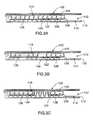
- Tissue removal member 116is not limited to having one continuous helical projection; it may comprise a plurality of discrete projections that are either continuous or discontinuous over the length of the shaft, as shown in FIG. 3B .
- the geometry of the outwardly extending projectionsmay vary in the thickness of the projections, the distance between projections, or in any other way that does not affect the functionality of the device.
- the diameter of projections 126may be constant or may vary.
- projections 126may be sized such that tissue removal member 116 fits exactly within sheath 102 , or projections 126 may be sized such that the diameter of tissue removal member 116 is smaller than the inner diameter of sheath 102 .
- shaft 128is not limited to one continuous shaft, and may comprise a plurality of shaft segments as shown in FIG. 3C .
- Distal end 136 of shaft 128 of tissue removal member 116may have many shapes, and the invention is not limited in this regard.
- distal end 136may be blunt, sharp, rounded, or otherwise shaped.
- distal portion 134may be straight, bent, curved, beveled, or otherwise fashioned.
- outwardly extending projections 126may be welded to shaft 128 . In another embodiment, outwardly extending projections 126 may be integrally formed with shaft 128 .
- Shaft 128can be manufactured from a number of different materials. These include, but are not limited to, stainless steels, shape-memory materials such as nickel titanium alloys, polyesters, polyethylenes, polyurethanes, polyimides, nylons, copolymers thereof, and medical grade plastics. Furthermore, any combination of the above materials may be used to optimize the physical properties of apparatus 100 . For example, a plastic coating disposed on a metal core may optimize flexibility and strength.
- Outwardly extending projections 126may be manufactured from a number of different materials, including but not limited to stainless steels, nitinol, and various plastics and polymers. Outwardly extending projections 126 may be attached to shaft 128 by welding, for example laser welding, or by any other suitable method of joining two such components, such as crimping, soldering, or the use of adhesives. Alternatively, as mentioned above, projections 126 may be integrally formed with shaft 128 during the manufacturing process. In other words, shaft 128 and projections 126 may be manufactured or machined as one single device, such as the case of a screw or a drill-bit.
- shaft 128may be at least partially coated with a substantially lubricious material.
- a substantially lubricious materialwould be one that facilitates movement of shaft 128 through elongate member 102 .
- the inner surface of elongate member 102may be coated with such a material.
- Suitable lubricious materialsinclude, but are not limited to, polytetrafluoroethylene, parylene, or tungstenite.
- Tissue removal member 116may generally be between about 6 inches and about 18 inches in length, more specifically between about 10.0 inches and about 13.5 inches.
- the diameter of shaft 128may generally be between about 0.012 inches and about 0.042 inches, more specifically between about 0.016 inches and about 0.028 inches.
- the width of outwardly extending projections 126may generally be between about 0.003 inches and about 0.025 inches, more specifically between about 0.005 inches and about 0.010 inches.
- apparatus 100may comprise a receptacle for housing and/or viewing the tissue that is removed from the body.
- a receptaclemay be referred to as a collection chamber.
- Collection chamber 138may be manufactured in a variety of sizes depending on the application.
- collection chamber 138may be structured to be coaxial with elongate member 102 and tissue removal member 116 .
- collection chamber 138may be located at, for example adjacent to, proximal portion 104 of elongate member 102 , wherein proximal end 106 of elongate member 102 and distal portion 604 of collection chamber 138 are operatively connected, for example joined by a hub or lock 144 .
- Hub or lock 144may be a luer lock, snap fit, or any other type of hub or joining mechanism that does not interfere with the functioning of apparatus 100 .
- proximal portion 104 of elongate member 102may define an opening such that tissue may exit therethrough and enter collection chamber 138 . In the embodiment shown in FIG. 6 , the opening is defined by proximal end 106 of elongate member 102 .
- proximal portion 104 of elongate member 102may comprise one or more openings, for example in a lateral wall thereof, for allowing tissue to pass therethrough into collection chamber 138 .
- a means for tissue to exit proximal portion 104 of elongate member 102is not limited to openings, and may include other means such as tubing, for example.
- collection chamber 138may be structured to receive tissue exiting proximal portion 104 of elongate member 102 .
- distal portion 604 of collection chamber 138may define a hole or other opening that is aligned with open proximal end 106 of elongate member 102 , such that tissue may exit elongate member 102 through open proximal end 106 and enter collection chamber 138 through the hole defined by distal portion 604 .
- tissue removal member 116may extend through open proximal end 106 of elongate member 102 into, and optionally through, collection chamber 138 , such that tissue may be deposited or viewed therein.
- hub or lock 144may be structured such that it does not interfere with the passage of tissue from elongate member 102 into collection chamber 138 , and such that it allows tissue removal member 116 to extend from within the lumen of elongate member 102 , through open proximal end 106 , and into collection chamber 138 .
- outwardly extending projections 126 of tissue removal member 116may end at a position within collection chamber 138 . This may help to ensure that the tissue is deposited within collection chamber 138 .
- Shaft 128 of tissue removal member 116may further extend through proximal portion 602 of collection chamber 138 .
- collection chambermay be structured to be coupled to handpiece 140 .
- proximal portion 602 of collection chamber 138may be joined to the distalmost portion of handpiece 140 with hub or lock 146 .
- Hub or lock 146may be a luer lock, snap fit, or any other hub or mechanism of joining that does not interfere with the functioning of apparatus 100 .
- the collection chamber assemblymay comprise a gasket 600 or any other device that would prevent tissue from exiting proximal portion 602 of collection chamber 138 . In the specific embodiment shown in FIG.
- distal portion 604 of collection chamber 138is operatively connected to elongate member 102
- proximal portion 602 of collection chamber 138is operatively connected to handpiece 140
- shaft 128 of tissue removal member 116runs through collection chamber 138 and into handpiece 140 .
- collection chamber 138may be located within handpiece 140 .
- collection chamber 138may be structured to allow the user to visualize the contents of the chamber. This may be accomplished by manufacturing collection chamber 138 from a material that is clear, translucent, transparent, or otherwise pervious to light. Such materials include, but are not limited to, polycarbonate, polyvinylchloride, and polypropylene.
- collection chamber 138may include means for measuring the amount of tissue that is contained therein. The means may comprise, but are not limited to, volume markings on the chamber, a movable indicator that may be displaced by the tissue, or an electrically conductive marker that may lead to auto-shutoff when a certain amount of tissue has been removed.
- the moveable indicatormay be structured such that it can be preset by the user at a particular location, thus facilitating the removal of a particular predetermined amount of tissue.
- collection chamber 138may be structured to be detached from apparatus 100 while still maintaining the tissue within collection chamber 138 . This may be accomplished by unscrewing or otherwise detaching collection chamber 138 from handle 140 and elongate member 102 , and sliding collection chamber 138 off of apparatus 100 . Collection chamber 138 can then be capped or otherwise closed or sealed with a snap-on cap, screw-cap, or any other means of sealing or closing collection chamber 138 . This embodiment may allow for the tissue to be sent for further analysis, for example to a pathology laboratory. Persons skilled in the art will recognize that in some cases, tissue may stick to shaft 128 of tissue removal member 116 .
- shaft 128may be structured to be removed from handpiece 140 such that tissue can be slid or pulled off the proximal end of shaft 128 .
- a non-stick coatingsuch as Teflon, may be included on the portion of the shaft that is within collection chamber 138 to prevent tissue from sticking.
- collection chamber 138may comprise a removable collection vessel, sac, or pouch for ease of tissue removal. This would be particularly useful in cases where collection chamber 138 is multi-use and requires sterilization
- apparatus 100may include handpiece 140 .
- the shape of handpiece 140 as shown in the embodiment of FIG. 1may allow for the user to grip and manipulate the apparatus in a number of different ways.
- the usermay grasp handpiece 140 using an overhand “screwdriver” grip. This grip may be beneficial for coarse movements such as insertion.
- the usermay employ a “pencil” grip. This grip may be beneficial for fine or delicate movements, such as the navigation of apparatus 100 to the appropriate tissue.
- These techniques for gripping handpiece 140are given as examples only, and are not meant to limit the manner in which the user may grip the handpiece.
- a switch 142may be recessed radially on handpiece 140 , as shown in FIG. 1 , thereby helping to prevent apparatus 100 from being inadvertently engaged.
- handpiece 140may comprise a latch or guard to prevent switch 142 from being inadvertently engaged.
- Handpiece 140may generally be sized to accommodate a number of hand sizes. In a specific embodiment, handpiece 140 may be structured to allow a user to easily grasp and manipulate the apparatus.
- handpiece 140may be structured to house a battery 502 , a motor 500 , and electrical connections 110 therebetween.
- switch 142may be located on handpiece 140 , thereby rendering apparatus 100 self contained and/or wireless.
- handpiece 140may include an opening 504 for proximal end 130 of shaft 128 to enter handpiece 140 .
- handpiece 140may include an aperture for the electrical connections joining the motor to the shaft to exit therethrough.
- the distalmost portion of handpiece 140may connected to proximal end 106 of elongate member 102 .
- connectionmay be temporary via a luer lock, a snap fit, or any other type of anchoring, or may be permanent via the use of adhesives.
- the connectionmay allow shaft 128 of the tissue removal member 116 to extend therethrough.
- handpiece 140is preferably hollow and defines a lumen.
- Handpiece 140may be manufactured from a number of different materials, including, but not limited to, molded plastics. In one embodiment handpiece 140 may be formed from two pieces of molded material that are sealed together with an adhesive or other appropriate sealing technique. This would allow for motor 500 , battery 502 , or any other desired items to be contained within the handpiece.
- tissue removal member 116may be operatively connected to a source of motorized rotational energy, for example a motor 500 , to allow for rotation of tissue removal member 116 .
- Proximal end 118 of tissue removal member 116may be operatively connected to motor 500 by any one or more of a variety of means for connecting, including but not limited to, flexible tubing, a ball bearing joint, and a spring.
- the means for connectingmay be flexible such that tissue removal member 116 may pivot with respect to motor 500 .
- motor 500may be connected to battery 502 via standard electrical connections 110 ; however motor 500 may use an alternative source of power, such as a plug or cable for connecting directly to a power outlet or other power supply.
- Switch 142is under the control of the user and allows current to flow from the source of power to motor 500 when switch 142 in engaged.
- motor 500may cause shaft 128 of tissue removal member 116 to rotate, thereby rotating outwardly extending projections 126 and conveying tissue from the distal portion 122 of tissue removal member 116 to proximal portion 118 .
- Motor 500may be one of several types of motors including, but not limited to, a direct current motor, an alternating current motor, an air driven motor, or a piezoelectric motor.
- Battery 502may be disposable or rechargeable, and may further be one of several types of battery including, but not limited to, alkaline, nickel-cadmium, or lithium.
- Switch 142may be one of several types of switches including, but not limited to, a toggle, a button, a rocker, a single throw switch, or a double throw switch. Furthermore, switch 142 may be configured such that the user must hold the switch in the ‘on’ position for the motor to remain engaged.
- motor 500may be configured to rotate over a range of speeds rather than being limited to an ‘on’ or ‘off’ position.
- switch 142may be configured to permit adjustment of the speed by the user. The speed may generally range from about 200 to about 15,000 rotations per minute (RPM).
- the motormay include gears to adjust the torque or speed of rotation of the shaft.
- motor 500 and switch 142may be configured to allow tissue removal member 116 to rotate in an opposite direction. This may facilitate removal of tissue from apparatus 100 .
- apparatus 100may be modified to accommodate the bent sheath.
- helical projections 126may be absent over the portion of shaft 128 that is within the bend.
- segments of shaft 128may be absent at regions within the bend.
- the diameters of the shaft or helical projections or both the shaft and helical projectionsmay be reduced within the region of the bend with respect to the diameter of the sheath.
- the thickness of helical projections 126may be variable over the length of shaft 128 .
- the finish on the interior surface of sheath 102may be modified to reduce any friction that may occur between sheath 102 and tissue removal member 116 .
- the speed of rotation of the shaftmay be slowed, by using a geared motor, for example, in order to reduce any friction that may occur between sheath 102 and tissue removal member 116 .
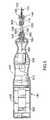
- apparatus 100may comprise an introducer apparatus that will aid in introducing elongate member 102 into the target tissue.
- the introducer apparatusmay include a hollow elongate introducer or cannula and an obturator.
- Cannula 700may be substantially stiff or rigid, such that it may assist in piercing skin or other body tissues, or such that it may provide support for apparatus 100 .
- Obturator 801may be structured to cooperatively engage with cannula 700 .
- obturator 801may be sized to fit within the lumen of cannula 700 and may comprise means for securing obturator 801 to cannula 700 .
- the outer diameter of obturator 801may be such that when obturator 801 is fully disposed within cannula 700 , obturator 801 sufficiently fills the lumen such that tissue is prevented from entering the lumen when the introducer device is inserted into the body.
- the distal tip of obturator 801may be sharp.
- the distal tip of obturator 801may be conical, beveled, or more specifically, tri-beveled.
- the lengths of obturator 801 and cannula 700may vary depending on the application.
- cannula 700will be sized such that distal end 702 can reach the target tissue within the body while the proximal end remains outside of the body. More specifically, cannula 700 may be between about 5.5 and about 7.5 inches in length, and obturator 801 may be between about 5.5 and about 7.5 inches in length. When the target tissue is an intervertebral disc, cannula 700 may be about 6.4 inches in length, and obturator 801 may be about 6.6 inches in length. Obturator 801 may be slightly longer than the cannula 700 , so that distal end 810 of the obturator may protrude from cannula 700 when fully disposed.
- the lumen of cannula 700may be sized to accommodate the diameter of elongate member 102 and obturator 801 , while remaining as small as possible in order to limit the invasiveness of the procedure.
- the proximal regions of cannula 700 and obturator 801are structured to be locked together with hub or lock 808 .
- the hub or lockcomprises means for securing cannula 700 to obturator 801 .
- cannula 700 and obturator 801may be made from a stainless steel. In other embodiments, cannula 700 , obturator 801 , or both may be made from other materials, such as nickel-titanium alloys for example.
- elongate member 102may be inserted through the lumen of cannula 700 in order to reach the target tissue.
- elongate member 102may comprise a marking 812 on proximal portion 104 , such that when distal end 110 of elongate member 102 and distal end 702 of cannula 700 are aligned, the marking will be aligned with the proximal end of cannula 700 .
- the markingmay take the form of a colored band, a dot, or a notch, for example. The use of the marking is discussed further hereinbelow.
- the length of cannula 700may comprise depth markings to aid the user in the placement of introducer apparatus. Such markings would be spaced at specific distances along the length of cannula 700 , for example at every inch. Such depth markings may be colored bands, notches, or dots for example.
- cannula 700includes a radiopaque marker 704 for visualizing the location of the cannula with respect to the target tissue using x-ray fluoroscopic imaging.
- radiopaque marker 704may be located on the distal portion of cannula 700 .
- a radiopaque markermay be included on distal tip 810 of obturator 801 . Examples of such markers are disclosed in U.S. patent applications US2005000079318 (publication number US20050159797A1), and US2003000382836 (publication number US20040176759A1), both of which are incorporated herein by reference.
- the distal portion of cannula 700may have one of a variety of configurations, including, but not limited to, straight, bent, or beveled.
- cannula 700is straight, while distal portion 108 of elongate member 102 is curved.
- elongate member 102may flexibly conform to the shape of cannula 700 while disposed within the introducer, but as it is passed through distal end 702 of cannula 100 it may reform to its curved shape.
- cannula 700may include a port such that a liquid may be delivered to the target tissue via cannula 700 .
- a portmay be located on the proximal region of the cannula, and may comprise a hub for joining a supply of liquid thereto.
- the introducer device described hereinabovemay be used with other devices that are structured to remove tissue from a nucleus pulposus.
- the use of the introducer deviceis therefore not limited to use with apparatus 100 .
- apparatus 100may be operable to deliver energy to a portion of the target tissue to further treat the tissue.
- This energymay comprise radiofrequency electrical energy, thermal energy, microwave energy, ultrasound energy, or optical energy (e.g. laser energy).
- apparatus 100may further comprise a probe operable to deliver energy, wherein probe refers to any element designed to deliver energy to a tissue.
- proberefers to any element designed to deliver energy to a tissue.
- the application of radio frequency energymay cause the heating of the tissue surrounding the probe. This may result in the shrinkage of the nucleus pulposus tissue, which may act to further treat the herniated disc. Examples of the use of energy to treat an intervertebral disc are disclosed in U.S. Pat. No. 6,896,675 (filed on 5 Mar. 2002) and U.S. patent application publication number US20050234445A1, incorporated herein by reference.
- apparatus 100may comprise means for measuring pressure within a patient's body.
- means for measuring pressureare a pressure transducer, or a fluid filled lumen for transmitting pressure.
- a pressure transducerfor example, in the case of an intervertebral disc, there is an intrinsic pressure associated with the nucleus pulposus tissue, and the pressure may be heightened in the case of a diseased disc. The initial pressure, change in pressure, or final pressure may be used to determine the amount of tissue to be removed from the disc.
- a pressure sensormay be located in distal portion 108 of elongate member 102 or distal portion 134 of shaft 128 , or alternatively, on a separate instrument introduced into the target tissue.
- electronic circuitrymay be provided to cause an auto-shutoff of apparatus 100 when a certain pressure has been reached.
- apparatus 100may comprise means for measuring the electrical impedance within a patient's body. This feature may be useful, for example, in ensuring the proper placement of apparatus 100 in the target tissue.
- the impedance within the annulus fibrosis of an intervertebral discmay be different from that within the nucleus pulposus of the disc.
- a return electrodefor example, it may be possible to determine whether distal end 110 of elongate member 102 is in the annulus fibrosis or nucleus pulposus.
- apparatus 100may comprise sensing means for indicating whether tissue removal member 116 is contacting or engaging tissue.
- sensing meansmay include, but are not limited to, an element for measuring the torque required to turn motor 500 , an element for measuring the forces exerted on elongate member 102 , or an element for measuring the current drawn by motor 500 .
- the sensing meansmay be coupled to an indicator, such as a light or an LED, for indicating to the user that the tissue has been engaged.
- apparatus 100may comprise means for guiding distal end 110 of elongate member 102 in a desired direction.
- a pull-wiremay be coupled to distal end 110 of elongate member 102 , and may extend proximally to a point located outside of the patient's body. By pulling on the pull-wire, the user may cause distal end 110 of elongate member 102 to deflect to a location that is closer to a target site.
- apparatus 100may comprise measuring means for measuring the temperature at a particular position on the apparatus.
- Such meansmay include a thermocouple, thermistor, or resistance thermometer, for example.
- the temperature measurement meansmay be located on distal end 110 of sheath 102 , or distal end 136 of shaft 128 for example.
- the inventioncomprises methods for removal of tissue from a body, wherein the methods are a combination of coring and conveyance.
- the methods described hereinmay be used to remove various types of materials from a patient's body. Examples of such materials include, but are not limited to, tissue of an intervertebral disc (for example, the nucleus pulposus), tumor tissue (including, but not limited to, material from breast, colon, stomach, or liver tumors), bone tissue (for example, bone marrow), cyst material, adipose tissue, eye material, cartilage, or atherosclerotic material.
- the general method for removing materialmay substantially comprise similar steps (i.e. coring and conveyance of material) regardless of the material being removed
- the method of introducing the apparatus into, or removing the apparatus from, the target sitemay vary depending on the material and/or target site.
- an instrument for penetrating bonefor example a hammer or a reamer, may be used to access the portion of the bone where the marrow is located.
- extra cautionmay be required to ensure that malignant cells do not track along the removal path of the sheath of the tissue removal member so that tumor material is not spread within the patient's body.
- the cauterization stepmay not be necessary, since the sheath of the tissue removal member doesn't contact tissue as it's removed from the patient's body.
- the method of the present inventionmay be practiced using apparatus 100 , including tissue removal member 116 disposed within elongate member 102 , as described hereinabove.
- apparatus 100including tissue removal member 116 disposed within elongate member 102 , as described hereinabove.
- embodiments of the method of the present inventionmay be practiced using any device that provides substantially similar functionality with respect to the steps of coring and conveying material.
- the steps of one embodiment of the methodmay be described generally as follows: patient preparation, insertion of the apparatus, activation of the apparatus, removal of the apparatus and patient recovery.
- a usermay desire to analyze the tissue removed during the procedure.
- the step of patient preparationmay comprise acquiring patient data in order to prepare for the procedure as well as positioning the patient appropriately.
- Pertinent data to be acquiredmay include, but is not limited to, a medical history of the patient, standard diagnostic test results (e.g. blood tests), physical function and pain assessments and medical imaging assessments of the patient's condition.
- the patientmay be assessed using various imaging, modalities such as MRI, X-ray, CT scan or ultrasound prior to the tissue removal procedure. These assessments may aid in determining the appropriate location of the target site for tissue removal as well as the amount of tissue to be removed.
- the patientPrior to commencing the procedure, the patient may be positioned in a prone position (depending on the target site and the material being removed) and prepared using standard pre-surgical techniques.
- the apparatusmay be inserted to the target site within the patient's body.
- the location and angle of insertionmay depend on the target site and the specific material being removed.
- the physicianmay insert the apparatus into the foraminal and pedicle zones, superior to the articular process, below the exiting spinal nerve, 200 to 400 from the sagittal plane, and roughly equidistant from the superior and inferior endplates.
- the placement of distal end 110 of elongate member 102 at the target sitemay be aided with the use of an introducer apparatus.
- the introducer apparatuscomprises an obturator 801 disposed within a cannula 700 .
- the introducer apparatusis advanced either percutaneously or in an open surgical procedure into the body of the patient and towards the target site.
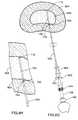
- obturator 801is withdrawn proximally from cannula 700 , leaving a distal end 702 of cannula 700 at the target site, for example as shown in FIGS. 8C and 8D .
- distal end 702 of cannula 700is positioned at the boundary between the annulus fibrosis 804 and the nucleus pulposus 806 (i.e. the inner wall of the intervertebral disc).
- cannula 700may comprise a radiopaque marker 704 to aid in the placement of the introducer apparatus.
- radiopaque marker 704may be included at distal end 702 of cannula 700 .
- radiopaque marker 704may be located elsewhere on cannula 700 .
- the placement of cannula 700may then be performed under fluoroscopy, such that the visibility of distal end 702 of cannula 700 may be enhanced on the fluoroscopic image by radiopaque marker 704 .
- various sensorsmay be used to assist in placing the introducer apparatus appropriately.
- an impedance measurement devicemay be included on distal end 702 of cannula 700 .
- the usermay measure the electrical impedance at distal end 702 of cannula 700 while inserting the cannula.
- the electrical impedance measurementindicates that distal end 702 of cannula 700 has passed through the annulus fibrosis and is within the nucleus pulposus, the user may stop the insertion process.
- a contrast solutionmay be injected at the target site through the lumen of cannula 700 in order to verify proper placement.
- the contrast solutionwhen viewed under fluoroscopy, may allow a user to visualize the boundary between the nucleus pulposus 806 and annulus fibrosis 804 .
- other substancesmay be injected through cannula 700 to the target site.
- the substancemay be injected through an injection port or hub coupled to cannula 700 .
- itmay be desirable to inject a fluid, including but not limited to an antibiotic, an anesthetic or an analgesic substance, prior to removing tissue from the target site.
- elongate member 102may be inserted through the lumen of cannula 700 .
- elongate member 102 and tissue removal member 116may be advanced through the lumen of cannula 700 , such that distal end 110 of elongate member 102 is located distal to distal end 702 of cannula 700 .
- the device having been inserted to the target sitemay proceed by activating the tissue removal member in order to remove tissue.
- This step of activating the devicemay generally include engaging the motor to rotate the device and advancing the device, including elongate member 102 , through the target site to core and convey a desired amount of material away from the target site. More specifically, in one embodiment, the user may advance distal end 110 of elongate member 102 into the target site, engage motor 500 , usually via switch 142 , and while motor 500 is engaged, advance apparatus 100 distally through the target site.
- motor 500may be disengaged, and elongate member 102 may be withdrawn proximally through the target site.
- elongate member 102may be repositioned by rotating elongate member 102 about its longitudinal axis, without requiring removal and re-insertion of elongate member 102 into the patient's body.
- Motor 500may then be re-engaged, and elongate member 102 may be advanced into a second region of the target site.
- the activation step of the tissue removal proceduremay be repeated until the desired volume of tissue has been removed.
- apparatus 100may be removed from the body, as discussed further below. It should be noted that, in some embodiments, only one pass of elongate member 102 may be required in order to remove the desired amount of tissue.
- tissue removal member 116remains substantially static or stationary with respect to the longitudinal axis of elongate member 102 . In other words, tissue removal member 116 does not move ‘in and out’ with respect to elongate member 102 .
- Apparatus 100is advanced through the target site to core the material to be removed. As apparatus 100 is advanced, material enters elongate member 102 through aperture 112 and is forced proximally into elongate member 102 by the advancement of apparatus 100 . In other words, material is substantially gathered into the lumen of elongate member 102 .
- tissue removal member 116which functions to convey the material proximally from distal portion 108 of elongate member 102 , to, for example, the exterior of the patient's body.
- Tissue removal member 116may function by a variety of mechanisms.
- tissue removal member 116is coupled to motor 500 . Upon engagement of motor 500 , tissue removal member 116 rotates about its longitudinal axis.
- tissue removal member 116will engage the tissue within elongate member 102 , and convey the tissue toward proximal end 120 of tissue removal member 116 .
- proximal portion 118 of tissue removal member 116is operatively connected to collection chamber 138 as described hereinabove.
- the tissuemay be conveyed from distal portion 108 of elongate member 102 and be deposited within chamber 138 .
- tissue removal member 116is recessed from distal tip 110 of elongate member 102 ; therefore the material does not contact tissue removal member 116 until after the material has entered the lumen of elongate member 102 .
- apparatus 100is advanced through the soft tissue of nucleus pulposus 806 to effect removal of the tissue as described above. As apparatus 100 is advanced, it may eventually contact annulus fibrosis 804 , the integrity of which is essential to the health of the disc. Due to the more rigid structure of the annulus fibrosis, it may be prevented from being cored into elongate member 102 , and therefore, due to the fact that tissue removal member 116 is recessed from distal tip 110 , the annulus fibrosis will not contact tissue removal member 116 . Thus, the annulus fibrosis may be protected from the high speed motion and projections of tissue removal member 116 .
- a clip 802sliding depth marker, or other marking mechanism may be used to indicate the location of distal end 110 of elongate member 102 within the patient's body.
- the usermay position distal end 110 of elongate member 102 at the boundary of annulus fibrosis 804 and nucleus pulposus 806 , as described above with respect to the positioning step. As shown in FIGS. 8G to 8L , a clip 802 , sliding depth marker, or other marking mechanism may be used to indicate the location of distal end 110 of elongate member 102 within the patient's body.
- the usermay position distal end 110 of elongate member 102 at the boundary of annulus fibrosis 804 and nucleus pulposus 806 , as described above with respect to the positioning step.
- the usermay then advance elongate member 102 distally through nucleus pulposus 806 , without activating tissue removal member 116 , until distal end 110 of elongate member 102 contacts annulus fibrosis 804 on the anterior side or portion of the disc.
- This point of contactmay be referred to the as the “anterior annulus inner wall” of the intervertebral disc.
- the boundary between nucleus pulposus 806 and annulus fibrosis 804may be located by tactile sensation, as the annulus fibrosis 804 is generally stiffer than the nucleus pulposus 806 , or by using a contrast solution and performing the method under fluoroscopy, as described hereinabove.
- proximal portion 104 of elongate member 102may comprise a marking 812 located such that when the marking is aligned with the proximal end of cannula 700 , it indicates that the distal ends of cannula 700 and elongate member 102 are aligned.
- the userwhen elongate member 102 is withdrawn proximally through the disc, the user will know to stop retracting elongate member 102 when marking 812 is aligned with the proximal end of cannula 700 .
- the usermay then engage tissue removal member 116 , and begin the coring and conveyance procedure.
- the usermay stop advancing apparatus 100 through the disc as marker or clip 802 approaches the proximal end of cannula 700 .
- the usermay then withdraw apparatus 100 by realigning the marking with the proximal end of cannula 700 , and repeat the coring and conveying step.
- marker or clip 802may help to ensure that distal end 110 of elongate member 102 does not contact annulus fibrosis 804 . This may be especially advantageous in the case of a severely damaged disc that may be severely affected by damage to annulus fibrosis 804 .
- Termination of the proceduremay be decided by a user, which decision may be facilitated in one or more ways by the apparatus being used.
- the proceduremay be terminated once a sufficient amount of tissue has been removed.
- the amount of tissue to be removedmay be up to 3.0 grams, more specifically, between 0.05 and 1.5 grams.
- collection chamber 138is at least partially pervious to light and comprises volume markings for determining the amount of tissue held within chamber 138 . By visualizing the markings and/or the contents of collection chamber 138 , the user may decide when the desired amount of tissue has been removed.
- collection chamber 138may comprise a sensing means for automatically indicating when a desired amount of tissue has been removed.
- collection chamber 138may be fitted with a sensor, including but not limited to a pressure, optical or chemical sensor, such that the sensor may provide an indication to the user once a desired amount of tissue has been collected.
- the sensormay be movable so that the user can adjust for the desired amount of tissue for a given procedure.
- tissuemay be collected and, once the amount of tissue collected is such that the tissue contacts the sensor, the sensor may provide an indication, for example, a visible or audible indication, that the desired amount of tissue has been removed.
- a pressure monitoring devicemay be coupled to apparatus 100 .
- the usermay determine when the desired amount of tissue has been removed.
- the pressure monitoring devicemay be operable to provide an indication to the user when the pressure has changed by a pre-determined amount.
- the indicationmay take the form of, for example, a visible or audible indication and may indicate to the user that the desired amount of tissue has been removed.
- the tissue removal membermay be removed from the patient's body.
- the step of removing these componentsmay include, in some embodiments, removing elongate member 102 from cannula 700 , injecting a substance through cannula 700 and removing cannula 700 from the patient's body.
- a fluidincluding but not limited to an antibiotic fluid, into the target site to prevent the possibility of infection.
- apparatus 100may be maneuvered by the user during, for example, the positioning, advancing, and removing steps, by grasping handpiece 140 in one or more of a variety of grips, as described hereinabove, and manipulating handpiece 140 to control the position of elongate member 102 and tissue removal member 116 at the target site.
- tissue removal member 116may be removed from tissue removal member 116 manually by scraping, tweezing or otherwise grasping and removing the material.
- chamber 138may be removed from apparatus 100 , sealed and/or capped and sent for analysis.
- motor 500may be run at high speeds in order to convey material up to collection chamber 138 prior to removal of chamber 138 .
- motor 500may be operable to run in reverse, such that material may be conveyed to distal portion 122 of tissue removal member 116 which may allow for easier removal of material from apparatus 100 , for example.
- apparatus 100may be used to introduce material into a patient's body.
- materialfor example, synthetic or natural (for example, xenobiotic) material or tissue, such as collagen or cement
- the materialmay be housed in receptacle 138 , and motor 500 may be run in the reverse direction from that used in the tissue removal process.
- tissue removal member 116may be referred to as a motorized device. The motorized device may engage the material housed in the receptacle, and convey it distally through the lumen of elongate element 102 and deposit it in the body.
- tissuemay be removed from the patient's body, and then material may be introduced into the patient's body.
- apparatus 100may be removed from the body and introducer apparatus, and the receptacle housing the tissue may be replaced with a receptacle housing the material to be introduced.
- Device 100may then be re-introduced into the patient's body, as described hereinabove, and the motor may be run in reverse to convey the material into the body.
- Device 100may be advanced and withdrawn within the target tissue in order to disperse the material.
- materialmay be introduced to the target site prior to removal of tissue from the patient's body.
- material other than tissuereferred to herein as a “second material”, such as previously introduced cements or pharmaceutical compounds, may be removed from the target site. This may be done either before or after the introduction of material, and before or after a step of removing tissue.
- the methodmay comprise a step of delivering energy to the target site before, during, or after removal of material.
- apparatus 100may include a probe or other device capable of delivering energy, as described hereinabove. The method may thus include placement of the probe at the target site, and activation of the probe to deliver energy. The user may advance or otherwise move the probe within the tissue, or may keep the probe stationary. Further details regarding such an embodiment may be found in co-pending U.S. patent application 20050234445 (published on 20 Oct. 2005), incorporated herein by reference.
- a second devicemay be separately introduced into the patient's body. This device may be used to aid in the collection of material. For example, as elongate member 102 and tissue removal member 116 are being operated at the target site, the secondary device may be used to push tissue towards elongate member 102 .
- the methodfurther comprises a step of disposing of apparatus 100 after use. This may be beneficial as single-use devices avoid several problems associated with reusable devices, including those associated with bacterial infections, viruses, and prions.
- the methodmay comprise one or more steps of variably adjusting the speed (i.e. rotations per minute—RPM) of motor 500 .
- motor 500is capable of rotating at various speeds, and the speed of motor 500 may be adjusted by the user.
- the usermay adjust the speed by using a control element such as a dial, lever, knob, or any other control element coupled to motor 500 .
- a usermay adjust the motor to run at a high speed as the user begins the tissue removal procedure, wherein a high speed may be desirable to assist in rapidly removing material.
- the usermay reduce the speed to ensure that an excess of tissue is not removed.
- the usermay desire to rotate tissue removal member 116 at a high speed to remove any tissue remaining in elongate member 102 or on tissue removal member 116 .
- the longitudinal motion of apparatus 100may be automated.
- the advancement of apparatus 100 into and through the target sitewould be automatic, rather than as a result of force applied by the user.
- this embodiment of the method of the present inventionis not intended to be limited to use within an intervertebral disc.
- Other tissues and/or materialsmay be removed from a patient's body using the steps described above.
- Embodiments of the present inventionthus provide for a minimally invasive apparatus that may be used to remove material, for example tissue from a patient's body, while minimizing blood loss and trauma to the patient.
Landscapes
- Health & Medical Sciences (AREA)
- Life Sciences & Earth Sciences (AREA)
- Surgery (AREA)
- Engineering & Computer Science (AREA)
- Animal Behavior & Ethology (AREA)
- Veterinary Medicine (AREA)
- Biomedical Technology (AREA)
- Heart & Thoracic Surgery (AREA)
- Medical Informatics (AREA)
- Molecular Biology (AREA)
- Nuclear Medicine, Radiotherapy & Molecular Imaging (AREA)
- General Health & Medical Sciences (AREA)
- Public Health (AREA)
- Orthopedic Medicine & Surgery (AREA)
- Neurology (AREA)
- Neurosurgery (AREA)
- Physics & Mathematics (AREA)
- Plasma & Fusion (AREA)
- Otolaryngology (AREA)
- Vascular Medicine (AREA)
- Surgical Instruments (AREA)
Abstract
Description
Claims (18)
Priority Applications (2)
| Application Number | Priority Date | Filing Date | Title |
|---|---|---|---|
| US11/368,508US8201563B2 (en) | 2005-03-11 | 2006-03-07 | Method for introducing materials into a body |
| US13/526,804US8505545B2 (en) | 2005-03-11 | 2012-06-19 | Method of and device for introducing materials into a body |
Applications Claiming Priority (3)
| Application Number | Priority Date | Filing Date | Title |
|---|---|---|---|
| US59410905P | 2005-03-11 | 2005-03-11 | |
| US11/128,342US8043287B2 (en) | 2002-03-05 | 2005-05-13 | Method of treating biological tissue |
| US11/368,508US8201563B2 (en) | 2005-03-11 | 2006-03-07 | Method for introducing materials into a body |
Related Parent Applications (1)
| Application Number | Title | Priority Date | Filing Date |
|---|---|---|---|
| US11/128,342Continuation-In-PartUS8043287B2 (en) | 2002-03-05 | 2005-05-13 | Method of treating biological tissue |
Related Child Applications (1)
| Application Number | Title | Priority Date | Filing Date |
|---|---|---|---|
| US13/526,804ContinuationUS8505545B2 (en) | 2005-03-11 | 2012-06-19 | Method of and device for introducing materials into a body |
Publications (2)
| Publication Number | Publication Date |
|---|---|
| US20060206131A1 US20060206131A1 (en) | 2006-09-14 |
| US8201563B2true US8201563B2 (en) | 2012-06-19 |
Family
ID=36952920
Family Applications (10)
| Application Number | Title | Priority Date | Filing Date |
|---|---|---|---|
| US11/128,342Expired - LifetimeUS8043287B2 (en) | 2002-03-05 | 2005-05-13 | Method of treating biological tissue |
| US11/368,505AbandonedUS20060206129A1 (en) | 2005-03-11 | 2006-03-07 | Tissue removal apparatus |
| US11/368,491AbandonedUS20060206128A1 (en) | 2005-03-11 | 2006-03-07 | Tissue removal apparatus |
| US11/368,509Active2029-02-20US8096957B2 (en) | 2005-03-11 | 2006-03-07 | Method for removing material from a patient's body |
| US11/368,475AbandonedUS20060206127A1 (en) | 2005-03-11 | 2006-03-07 | Method for removing material from a patient's body |
| US11/368,508Active2030-03-04US8201563B2 (en) | 2005-03-11 | 2006-03-07 | Method for introducing materials into a body |
| US11/368,506AbandonedUS20060206130A1 (en) | 2005-03-11 | 2006-03-07 | Tissue removal apparatus |
| US11/368,510AbandonedUS20060206133A1 (en) | 2005-03-11 | 2006-03-07 | Method for removing material from a patient's body |
| US11/368,513AbandonedUS20060206134A1 (en) | 2005-03-11 | 2006-03-07 | Method for removing material from a patient's body |
| US13/526,804Expired - Fee RelatedUS8505545B2 (en) | 2005-03-11 | 2012-06-19 | Method of and device for introducing materials into a body |
Family Applications Before (5)
| Application Number | Title | Priority Date | Filing Date |
|---|---|---|---|
| US11/128,342Expired - LifetimeUS8043287B2 (en) | 2002-03-05 | 2005-05-13 | Method of treating biological tissue |
| US11/368,505AbandonedUS20060206129A1 (en) | 2005-03-11 | 2006-03-07 | Tissue removal apparatus |
| US11/368,491AbandonedUS20060206128A1 (en) | 2005-03-11 | 2006-03-07 | Tissue removal apparatus |
| US11/368,509Active2029-02-20US8096957B2 (en) | 2005-03-11 | 2006-03-07 | Method for removing material from a patient's body |
| US11/368,475AbandonedUS20060206127A1 (en) | 2005-03-11 | 2006-03-07 | Method for removing material from a patient's body |
Family Applications After (4)
| Application Number | Title | Priority Date | Filing Date |
|---|---|---|---|
| US11/368,506AbandonedUS20060206130A1 (en) | 2005-03-11 | 2006-03-07 | Tissue removal apparatus |
| US11/368,510AbandonedUS20060206133A1 (en) | 2005-03-11 | 2006-03-07 | Method for removing material from a patient's body |
| US11/368,513AbandonedUS20060206134A1 (en) | 2005-03-11 | 2006-03-07 | Method for removing material from a patient's body |
| US13/526,804Expired - Fee RelatedUS8505545B2 (en) | 2005-03-11 | 2012-06-19 | Method of and device for introducing materials into a body |
Country Status (2)
| Country | Link |
|---|---|
| US (10) | US8043287B2 (en) |
| WO (1) | WO2006094405A1 (en) |
Cited By (7)
| Publication number | Priority date | Publication date | Assignee | Title |
|---|---|---|---|---|
| US20090281507A1 (en)* | 2008-05-12 | 2009-11-12 | Mayo Foundation For Medical Education And Research | Hemostatic Devices and Methods For Use Thereof |
| US8505545B2 (en)* | 2005-03-11 | 2013-08-13 | Kimberly-Clark, Inc. | Method of and device for introducing materials into a body |
| US20130274782A1 (en)* | 2012-04-16 | 2013-10-17 | Pacesetter, Inc. | Apparatus and method for pericardial access |
| USD707838S1 (en) | 2012-04-27 | 2014-06-24 | Bio 'N Ice GmbH | Light source with coupling adaptor for an ice tip |
| US20160030061A1 (en)* | 2014-08-04 | 2016-02-04 | DePuy Synthes Products, LLC | Flexible transport auger |
| US9511174B2 (en) | 2008-05-12 | 2016-12-06 | Humparkull, Llc | Hemostatic devices and methods for use thereof |
| US10426483B2 (en) | 2008-05-12 | 2019-10-01 | Mitchell R. Humphreys | Hemostatic devices and methods for use thereof |
Families Citing this family (145)
| Publication number | Priority date | Publication date | Assignee | Title |
|---|---|---|---|---|
| US8518036B2 (en) | 2002-03-05 | 2013-08-27 | Kimberly-Clark Inc. | Electrosurgical tissue treatment method |
| US6896675B2 (en) | 2002-03-05 | 2005-05-24 | Baylis Medical Company Inc. | Intradiscal lesioning device |
| US8882755B2 (en) | 2002-03-05 | 2014-11-11 | Kimberly-Clark Inc. | Electrosurgical device for treatment of tissue |
| US10973532B2 (en) | 2002-05-31 | 2021-04-13 | Teleflex Life Sciences Limited | Powered drivers, intraosseous devices and methods to access bone marrow |
| US7951089B2 (en) | 2002-05-31 | 2011-05-31 | Vidacare Corporation | Apparatus and methods to harvest bone and bone marrow |
| US11337728B2 (en) | 2002-05-31 | 2022-05-24 | Teleflex Life Sciences Limited | Powered drivers, intraosseous devices and methods to access bone marrow |
| US9072543B2 (en) | 2002-05-31 | 2015-07-07 | Vidacare LLC | Vascular access kits and methods |
| US8668698B2 (en) | 2002-05-31 | 2014-03-11 | Vidacare Corporation | Assembly for coupling powered driver with intraosseous device |
| US8641715B2 (en) | 2002-05-31 | 2014-02-04 | Vidacare Corporation | Manual intraosseous device |
| US7811260B2 (en) | 2002-05-31 | 2010-10-12 | Vidacare Corporation | Apparatus and method to inject fluids into bone marrow and other target sites |
| US10973545B2 (en) | 2002-05-31 | 2021-04-13 | Teleflex Life Sciences Limited | Powered drivers, intraosseous devices and methods to access bone marrow |
| EP2039298B1 (en) | 2002-05-31 | 2017-10-25 | Vidacare LLC | Apparatus to access bone marrow |
| US8361067B2 (en) | 2002-09-30 | 2013-01-29 | Relievant Medsystems, Inc. | Methods of therapeutically heating a vertebral body to treat back pain |
| US6907884B2 (en) | 2002-09-30 | 2005-06-21 | Depay Acromed, Inc. | Method of straddling an intraosseous nerve |
| US7258690B2 (en) | 2003-03-28 | 2007-08-21 | Relievant Medsystems, Inc. | Windowed thermal ablation probe |
| US9504477B2 (en) | 2003-05-30 | 2016-11-29 | Vidacare LLC | Powered driver |
| US7627380B2 (en)* | 2005-03-31 | 2009-12-01 | Covidien Ag | Method and apparatus for monitoring disc pressure during heat treatment of an intervertebral disc |
| US20070066881A1 (en) | 2005-09-13 | 2007-03-22 | Edwards Jerome R | Apparatus and method for image guided accuracy verification |
| EP1924198B1 (en) | 2005-09-13 | 2019-04-03 | Veran Medical Technologies, Inc. | Apparatus for image guided accuracy verification |
| US9867530B2 (en) | 2006-08-14 | 2018-01-16 | Volcano Corporation | Telescopic side port catheter device with imaging system and method for accessing side branch occlusions |
| US8944069B2 (en) | 2006-09-12 | 2015-02-03 | Vidacare Corporation | Assemblies for coupling intraosseous (IO) devices to powered drivers |
| EP3189787B1 (en) | 2006-09-12 | 2019-01-09 | Teleflex Medical Devices S.à.r.l. | Medical procedures trays and related methods |
| WO2008103606A2 (en)* | 2007-02-20 | 2008-08-28 | Gabriel Institute, Inc. | Bone drill and methods of treatment delivery |
| EP2178442B1 (en) | 2007-07-12 | 2017-09-06 | Volcano Corporation | Catheter for in vivo imaging |
| US9596993B2 (en) | 2007-07-12 | 2017-03-21 | Volcano Corporation | Automatic calibration systems and methods of use |
| WO2009009802A1 (en) | 2007-07-12 | 2009-01-15 | Volcano Corporation | Oct-ivus catheter for concurrent luminal imaging |
| WO2009065061A1 (en) | 2007-11-14 | 2009-05-22 | Myoscience, Inc. | Pain management using cryogenic remodeling |
| SG154343A1 (en)* | 2008-01-08 | 2009-08-28 | Ting Choon Meng | Method and apparatus for intra-articular injection or aspiration |
| EP2259712A1 (en)* | 2008-03-03 | 2010-12-15 | Geisert Square Gmbh | Intervertebral disc analysis system and method |
| US8390291B2 (en)* | 2008-05-19 | 2013-03-05 | The Board Of Regents, The University Of Texas System | Apparatus and method for tracking movement of a target |
| US10028753B2 (en) | 2008-09-26 | 2018-07-24 | Relievant Medsystems, Inc. | Spine treatment kits |
| CA2737374C (en) | 2008-09-26 | 2017-03-28 | Relievant Medsystems, Inc. | Systems and methods for navigating an instrument through bone |
| US8142463B2 (en)* | 2009-03-13 | 2012-03-27 | Kyphon Sarl | Battery operated nucleus disruptor device for intervertebral disc |
| US8632534B2 (en) | 2009-04-03 | 2014-01-21 | Angiodynamics, Inc. | Irreversible electroporation (IRE) for congestive obstructive pulmonary disease (COPD) |
| WO2010138919A2 (en) | 2009-05-28 | 2010-12-02 | Angiodynamics, Inc. | System and method for synchronizing energy delivery to the cardiac rhythm |
| CH701320B1 (en)* | 2009-06-16 | 2013-10-15 | Frii S A | A device for resection treatments / endoscopic tissue removal. |
| US9895189B2 (en) | 2009-06-19 | 2018-02-20 | Angiodynamics, Inc. | Methods of sterilization and treating infection using irreversible electroporation |
| EP3556308B1 (en) | 2009-11-05 | 2023-12-20 | Stratus Medical, LLC | Systems for spinal radio frequency neurotomy |
| KR101632429B1 (en) | 2010-05-21 | 2016-06-21 | 님버스 컨셉츠, 엘엘씨 | Systems and methods for tissue ablation |
| EP2627274B1 (en) | 2010-10-13 | 2022-12-14 | AngioDynamics, Inc. | System for electrically ablating tissue of a patient |
| US9107691B2 (en) | 2010-10-19 | 2015-08-18 | Distal Access, Llc | Apparatus for rotating medical devices, systems including the apparatus, and associated methods |
| US8845621B2 (en)* | 2010-10-19 | 2014-09-30 | Distal Access, Llc | Apparatus for rotating medical devices, systems including the apparatus, and associated methods |
| US11141063B2 (en) | 2010-12-23 | 2021-10-12 | Philips Image Guided Therapy Corporation | Integrated system architectures and methods of use |
| US9486275B2 (en) | 2010-12-30 | 2016-11-08 | Avent, Inc. | Electrosurgical apparatus having a sensor |
| US20120172905A1 (en)* | 2010-12-30 | 2012-07-05 | Kimberly-Clark, Inc. | Tissue Removal Apparatus and Method of Manufacturing Same |
| US20120172907A1 (en)* | 2010-12-30 | 2012-07-05 | Kimberly-Clark, Inc. | Tissue Removal Apparatus |
| US11040140B2 (en) | 2010-12-31 | 2021-06-22 | Philips Image Guided Therapy Corporation | Deep vein thrombosis therapeutic methods |
| US9360630B2 (en) | 2011-08-31 | 2016-06-07 | Volcano Corporation | Optical-electrical rotary joint and methods of use |
| EP2750595B1 (en) | 2011-09-02 | 2021-02-24 | Battelle Memorial Institute | Wireless and power-source-free extravasation and infiltration detection sensor |
| US9078665B2 (en) | 2011-09-28 | 2015-07-14 | Angiodynamics, Inc. | Multiple treatment zone ablation probe |
| US20130150752A1 (en)* | 2011-12-12 | 2013-06-13 | Karl W. Swann | Apparatus for Bone Aspiration |
| AU2012362524B2 (en) | 2011-12-30 | 2018-12-13 | Relievant Medsystems, Inc. | Systems and methods for treating back pain |
| US9414881B2 (en) | 2012-02-08 | 2016-08-16 | Angiodynamics, Inc. | System and method for increasing a target zone for electrical ablation |
| EP2816966B1 (en) | 2012-02-22 | 2023-10-25 | Veran Medical Technologies, Inc. | Steerable surgical catheter comprising a biopsy device at the distal end portion thereof |
| TWI533897B (en)* | 2012-04-27 | 2016-05-21 | 鄭明輝 | Fat removal device |
| US10278676B2 (en)* | 2012-06-27 | 2019-05-07 | Michael J. Vaillancourt | Safety shield for a needle assembly |
| US10588691B2 (en) | 2012-09-12 | 2020-03-17 | Relievant Medsystems, Inc. | Radiofrequency ablation of tissue within a vertebral body |
| US10568586B2 (en) | 2012-10-05 | 2020-02-25 | Volcano Corporation | Systems for indicating parameters in an imaging data set and methods of use |
| US10070827B2 (en) | 2012-10-05 | 2018-09-11 | Volcano Corporation | Automatic image playback |
| US11272845B2 (en) | 2012-10-05 | 2022-03-15 | Philips Image Guided Therapy Corporation | System and method for instant and automatic border detection |
| CA2887421A1 (en) | 2012-10-05 | 2014-04-10 | David Welford | Systems and methods for amplifying light |
| US20140100454A1 (en) | 2012-10-05 | 2014-04-10 | Volcano Corporation | Methods and systems for establishing parameters for three-dimensional imaging |
| US9307926B2 (en) | 2012-10-05 | 2016-04-12 | Volcano Corporation | Automatic stent detection |
| US9292918B2 (en) | 2012-10-05 | 2016-03-22 | Volcano Corporation | Methods and systems for transforming luminal images |
| US9324141B2 (en) | 2012-10-05 | 2016-04-26 | Volcano Corporation | Removal of A-scan streaking artifact |
| US9367965B2 (en) | 2012-10-05 | 2016-06-14 | Volcano Corporation | Systems and methods for generating images of tissue |
| US9286673B2 (en) | 2012-10-05 | 2016-03-15 | Volcano Corporation | Systems for correcting distortions in a medical image and methods of use thereof |
| US9858668B2 (en) | 2012-10-05 | 2018-01-02 | Volcano Corporation | Guidewire artifact removal in images |
| US9840734B2 (en) | 2012-10-22 | 2017-12-12 | Raindance Technologies, Inc. | Methods for analyzing DNA |
| WO2014071161A1 (en) | 2012-11-05 | 2014-05-08 | Relievant Medsystems, Inc. | System and methods for creating curved paths through bone and modulating nerves within the bone |
| JP6317751B2 (en) | 2012-11-08 | 2018-04-25 | ボストン サイエンティフィック サイムド,インコーポレイテッドBoston Scientific Scimed,Inc. | System for performing medical procedures |
| EP2931132B1 (en) | 2012-12-13 | 2023-07-05 | Philips Image Guided Therapy Corporation | System for targeted cannulation |
| US10942022B2 (en) | 2012-12-20 | 2021-03-09 | Philips Image Guided Therapy Corporation | Manual calibration of imaging system |
| US11406498B2 (en) | 2012-12-20 | 2022-08-09 | Philips Image Guided Therapy Corporation | Implant delivery system and implants |
| WO2014113188A2 (en) | 2012-12-20 | 2014-07-24 | Jeremy Stigall | Locating intravascular images |
| US10939826B2 (en) | 2012-12-20 | 2021-03-09 | Philips Image Guided Therapy Corporation | Aspirating and removing biological material |
| EP2934311B1 (en) | 2012-12-20 | 2020-04-15 | Volcano Corporation | Smooth transition catheters |
| WO2014100761A2 (en)* | 2012-12-20 | 2014-06-26 | Spine View, Inc. | Discectomy devices and methods |
| EP2934310A4 (en) | 2012-12-20 | 2016-10-12 | Nathaniel J Kemp | Optical coherence tomography system that is reconfigurable between different imaging modes |
| EP2936241B1 (en) | 2012-12-21 | 2020-10-21 | Nathaniel J. Kemp | Power-efficient optical buffering using a polarisation-maintaining active optical switch |
| US9486143B2 (en) | 2012-12-21 | 2016-11-08 | Volcano Corporation | Intravascular forward imaging device |
| US9612105B2 (en) | 2012-12-21 | 2017-04-04 | Volcano Corporation | Polarization sensitive optical coherence tomography system |
| CA2895769A1 (en) | 2012-12-21 | 2014-06-26 | Douglas Meyer | Rotational ultrasound imaging catheter with extended catheter body telescope |
| EP2934323A4 (en) | 2012-12-21 | 2016-08-17 | Andrew Hancock | SYSTEM AND METHOD FOR MULTIPLE PROCESSING OF IMAGE SIGNALS |
| US20140180316A1 (en)* | 2012-12-21 | 2014-06-26 | Volcano Corporation | Imaging and removing biological material |
| JP2016507892A (en) | 2012-12-21 | 2016-03-10 | デイビッド ウェルフォード, | System and method for narrowing the wavelength emission of light |
| US10058284B2 (en) | 2012-12-21 | 2018-08-28 | Volcano Corporation | Simultaneous imaging, monitoring, and therapy |
| US10413317B2 (en) | 2012-12-21 | 2019-09-17 | Volcano Corporation | System and method for catheter steering and operation |
| US10332228B2 (en) | 2012-12-21 | 2019-06-25 | Volcano Corporation | System and method for graphical processing of medical data |
| JP2016501625A (en) | 2012-12-21 | 2016-01-21 | ジェローム マイ, | Ultrasound imaging with variable line density |
| US9402602B2 (en) | 2013-01-25 | 2016-08-02 | Choon Kee Lee | Tissue sampling apparatus |
| US20140257483A1 (en)* | 2013-03-05 | 2014-09-11 | Karl W. Swann | Method and device for cervical bone marrow aspiration for use in an anterior cervical discectomy and fusion procedure |
| WO2014138555A1 (en) | 2013-03-07 | 2014-09-12 | Bernhard Sturm | Multimodal segmentation in intravascular images |
| US10226597B2 (en) | 2013-03-07 | 2019-03-12 | Volcano Corporation | Guidewire with centering mechanism |
| US20140276923A1 (en) | 2013-03-12 | 2014-09-18 | Volcano Corporation | Vibrating catheter and methods of use |
| EP2967391A4 (en) | 2013-03-12 | 2016-11-02 | Donna Collins | SYSTEMS AND METHODS FOR DIAGNOSING CORONARY MICROVASCULAR DISEASE |
| US11026591B2 (en) | 2013-03-13 | 2021-06-08 | Philips Image Guided Therapy Corporation | Intravascular pressure sensor calibration |
| WO2014159819A1 (en) | 2013-03-13 | 2014-10-02 | Jinhyoung Park | System and methods for producing an image from a rotational intravascular ultrasound device |
| US9301687B2 (en) | 2013-03-13 | 2016-04-05 | Volcano Corporation | System and method for OCT depth calibration |
| US20160030151A1 (en) | 2013-03-14 | 2016-02-04 | Volcano Corporation | Filters with echogenic characteristics |
| US10219887B2 (en) | 2013-03-14 | 2019-03-05 | Volcano Corporation | Filters with echogenic characteristics |
| US10292677B2 (en) | 2013-03-14 | 2019-05-21 | Volcano Corporation | Endoluminal filter having enhanced echogenic properties |
| US12343198B2 (en) | 2013-03-14 | 2025-07-01 | Philips Image Guided Therapy Corporation | Delivery catheter having imaging capabilities |
| EP2967591A4 (en)* | 2013-03-15 | 2017-02-15 | Interactive Neuroscience Center, LLC | Surgical device |
| US9603610B2 (en) | 2013-03-15 | 2017-03-28 | DePuy Synthes Products, Inc. | Tools and methods for tissue removal |
| US10064630B2 (en)* | 2013-03-15 | 2018-09-04 | Teleflex Medical Devices S.À R.L. | Driver assemblies, drivers, intraosseous devices, and methods for determining voltages and/or impedances in biological material |
| US9289265B2 (en)* | 2013-07-10 | 2016-03-22 | The Johns Hopkins University | MRI-compatible, integrated force and torque sensors and systems that incorporate the sensors |
| US9724151B2 (en) | 2013-08-08 | 2017-08-08 | Relievant Medsystems, Inc. | Modulating nerves within bone using bone fasteners |
| WO2015112810A1 (en) | 2014-01-24 | 2015-07-30 | Avent, Inc. | Traumatic wound dressing system with conformal cover |
| AU2015209240B2 (en) | 2014-01-24 | 2019-06-13 | Avent, Inc. | Traumatic wound dressing system with wrap |
| US20150305612A1 (en) | 2014-04-23 | 2015-10-29 | Mark Hunter | Apparatuses and methods for registering a real-time image feed from an imaging device to a steerable catheter |
| US20150305650A1 (en) | 2014-04-23 | 2015-10-29 | Mark Hunter | Apparatuses and methods for endobronchial navigation to and confirmation of the location of a target tissue and percutaneous interception of the target tissue |
| US10667836B2 (en) | 2014-04-28 | 2020-06-02 | Boston Scientific Scimed, Inc. | Tissue resectors, hand operated tissue resecting systems, and associated methods |
| US20160022346A1 (en)* | 2014-07-01 | 2016-01-28 | Cirrus Technologies Kft | Medical device and method of use |
| US12114911B2 (en) | 2014-08-28 | 2024-10-15 | Angiodynamics, Inc. | System and method for ablating a tissue site by electroporation with real-time pulse monitoring |
| US10631889B2 (en)* | 2014-12-16 | 2020-04-28 | Covidien Lp | Surgical device with incorporated tissue extraction |
| TWI593380B (en)* | 2015-03-23 | 2017-08-01 | 台灣微創醫療器材股份有限公司 | Medical device for improving biological tissue structure |
| US10786264B2 (en) | 2015-03-31 | 2020-09-29 | Medos International Sarl | Percutaneous disc clearing device |
| CA2899017A1 (en) | 2015-07-31 | 2017-01-31 | Shiva Jayaraman | Device for a laparoscopic surgery |
| EP3340913B1 (en) | 2015-08-28 | 2024-10-23 | Avent, Inc. | Liquid delivery for cooled rf system |
| SE541418C2 (en)* | 2016-01-22 | 2019-09-24 | S2Medical Ab | Minimally invasive tissue harvesting device |
| US10653431B2 (en) | 2016-06-14 | 2020-05-19 | Medos International Sarl | Drill assemblies and methods for drilling into bone |
| US10231846B2 (en) | 2016-08-19 | 2019-03-19 | Stryker European Holdings I, Llc | Bone graft delivery loading assembly |
| EP3522807B1 (en) | 2016-10-04 | 2025-07-09 | Avent, Inc. | Cooled rf probes |
| CN106333746A (en)* | 2016-10-31 | 2017-01-18 | 上海瑞柯恩激光技术有限公司 | Tissue crusher tool bit and laser treatment device |
| US10905492B2 (en) | 2016-11-17 | 2021-02-02 | Angiodynamics, Inc. | Techniques for irreversible electroporation using a single-pole tine-style internal device communicating with an external surface electrode |
| KR20190121772A (en) | 2017-02-27 | 2019-10-28 | 아벤트, 인크. | Methods and systems for improving the positioning accuracy of high frequency ablation procedures through reference marking |
| US11690645B2 (en) | 2017-05-03 | 2023-07-04 | Medtronic Vascular, Inc. | Tissue-removing catheter |
| EP4018946A1 (en) | 2017-05-03 | 2022-06-29 | Medtronic Vascular, Inc. | Tissue-removing catheter |
| CA3099451A1 (en)* | 2018-05-08 | 2019-11-14 | Baylis Medical Company Inc. | Methods and devices for puncturing tissue |
| US11000295B2 (en) | 2018-09-27 | 2021-05-11 | Acumed Llc | Bone harvesting system |
| FR3087107A1 (en) | 2018-10-15 | 2020-04-17 | Avent Inc. | Neural ablation compositions, systems, kits and methods |
| CN118697424A (en) | 2018-11-16 | 2024-09-27 | 美敦力瓦斯科尔勒公司 | Tissue Removal Catheter |
| USD915593S1 (en) | 2018-11-16 | 2021-04-06 | King Saud University | Endodontic bioactive materials obturator |
| US20200188015A1 (en)* | 2018-12-14 | 2020-06-18 | Avent, Inc. | Introducer for Use with an RF Ablation Probe and Associated RF Ablation Probe Assembly |
| USD885560S1 (en) | 2018-12-14 | 2020-05-26 | Avent, Inc. | Introducer hub with fluid delivery port |
| US11819236B2 (en) | 2019-05-17 | 2023-11-21 | Medtronic Vascular, Inc. | Tissue-removing catheter |
| AU2020346827A1 (en) | 2019-09-12 | 2022-03-31 | Relievant Medsystems, Inc. | Systems and methods for tissue modulation |
| EP3815632A1 (en) | 2019-10-30 | 2021-05-05 | Straub Medical AG | Catheter for aspiration, fragmentation and removal of removable material from hollow bodies |
| US20210369328A1 (en)* | 2020-06-02 | 2021-12-02 | Covidien Lp | System and user interface for displaying actual operating parameters and ideal operating parameters |
| US12011339B2 (en)* | 2020-08-25 | 2024-06-18 | Guy Francis Merz | Ears disimpactor |
| US12082876B1 (en) | 2020-09-28 | 2024-09-10 | Relievant Medsystems, Inc. | Introducer drill |
| EP4268150A4 (en) | 2020-12-22 | 2024-12-18 | Relievant Medsystems, Inc. | PREDICTION OF CANDIDATES FOR SPINAL NEUROMODULATION |
| US12433668B1 (en) | 2021-11-08 | 2025-10-07 | Relievant Medsystems, Inc. | Impedance stoppage mitigation during radiofrequency tissue ablation procedures |
| WO2024059734A1 (en)* | 2022-09-15 | 2024-03-21 | Biogennix, Llc | Auger-based bone harvesting and delivery |
Citations (174)
| Publication number | Priority date | Publication date | Assignee | Title |
|---|---|---|---|---|
| US2526662A (en) | 1946-12-10 | 1950-10-24 | Herbert E Hipps | Bone meal extractor |
| US3477423A (en) | 1967-01-09 | 1969-11-11 | Baxter Laboratories Inc | Biopsy instrument |
| US3732858A (en) | 1968-09-16 | 1973-05-15 | Surgical Design Corp | Apparatus for removing blood clots, cataracts and other objects from the eye |
| US3774612A (en)* | 1971-06-14 | 1973-11-27 | J Marco | Uterine evacuation assembly |
| US4177797A (en) | 1977-03-04 | 1979-12-11 | Shelby M. Baylis | Rotary biopsy device and method of using same |
| US4369788A (en) | 1980-01-31 | 1983-01-25 | Goald Harold J | Reversed forceps for microdisc surgery |
| US4411266A (en) | 1980-09-24 | 1983-10-25 | Cosman Eric R | Thermocouple radio frequency lesion electrode |
| US4512344A (en) | 1982-05-12 | 1985-04-23 | Barber Forest C | Arthroscopic surgery dissecting apparatus |
| US4600014A (en) | 1984-02-10 | 1986-07-15 | Dan Beraha | Transrectal prostate biopsy device and method |
| US4649919A (en) | 1985-01-23 | 1987-03-17 | Precision Surgical Instruments, Inc. | Surgical instrument |
| US4699154A (en) | 1986-02-19 | 1987-10-13 | Radiplast Ab | Tissue sampling device |
| US4834729A (en) | 1986-12-30 | 1989-05-30 | Dyonics, Inc. | Arthroscopic surgical instrument |
| US4857046A (en) | 1987-10-21 | 1989-08-15 | Cordis Corporation | Drive catheter having helical pump drive shaft |
| US4883458A (en) | 1987-02-24 | 1989-11-28 | Surgical Systems & Instruments, Inc. | Atherectomy system and method of using the same |
| US4907589A (en) | 1988-04-29 | 1990-03-13 | Cosman Eric R | Automatic over-temperature control apparatus for a therapeutic heating device |
| US4958625A (en) | 1989-07-18 | 1990-09-25 | Boston Scientific Corporation | Biopsy needle instrument |
| US4979939A (en) | 1984-05-14 | 1990-12-25 | Surgical Systems & Instruments, Inc. | Atherectomy system with a guide wire |
| US5002553A (en) | 1984-05-14 | 1991-03-26 | Surgical Systems & Instruments, Inc. | Atherectomy system with a clutch |
| US5027792A (en) | 1989-03-17 | 1991-07-02 | Percutaneous Technologies, Inc. | Endoscopic revision hip surgery device |
| EP0438242A1 (en) | 1990-01-12 | 1991-07-24 | Laserscope | Percutaneous diskectomy using a laser |
| US5074841A (en) | 1990-01-30 | 1991-12-24 | Microcision, Inc. | Atherectomy device with helical cutter |
| US5084052A (en) | 1989-02-09 | 1992-01-28 | Baxter International Inc. | Surgical cutting instrument with plurality of openings |
| USRE34056E (en) | 1989-07-31 | 1992-09-08 | C.R. Bard, Inc. | Tissue sampling device |
| US5167658A (en) | 1991-01-31 | 1992-12-01 | Mdt Corporation | Method and apparatus for electrosurgical measurement |
| US5183054A (en) | 1991-09-09 | 1993-02-02 | Sherwood Medical Company | Actuated biopsy cutting needle with removable stylet |
| US5233515A (en) | 1990-06-08 | 1993-08-03 | Cosman Eric R | Real-time graphic display of heat lesioning parameters in a clinical lesion generator system |
| US5234000A (en) | 1992-09-25 | 1993-08-10 | Hakky Said I | Automatic biopsy device housing a plurality of stylets |
| US5277201A (en) | 1992-05-01 | 1994-01-11 | Vesta Medical, Inc. | Endometrial ablation apparatus and method |
| US5334193A (en) | 1992-11-13 | 1994-08-02 | American Cardiac Ablation Co., Inc. | Fluid cooled ablation catheter |
| US5342357A (en) | 1992-11-13 | 1994-08-30 | American Cardiac Ablation Co., Inc. | Fluid cooled electrosurgical cauterization system |
| IT1246197B (en) | 1989-08-02 | 1994-11-16 | Aesculap Skidmore Holdings | Instrument for nucleotomy, particularly suitable for the removal of nuclear material from an intervertebral disc |
| US5383874A (en) | 1991-11-08 | 1995-01-24 | Ep Technologies, Inc. | Systems for identifying catheters and monitoring their use |
| US5383884A (en)* | 1992-12-04 | 1995-01-24 | American Biomed, Inc. | Spinal disc surgical instrument |
| US5423807A (en) | 1992-04-16 | 1995-06-13 | Implemed, Inc. | Cryogenic mapping and ablation catheter |
| US5423799A (en) | 1988-12-14 | 1995-06-13 | Medtronic, Inc. | Surgical instrument |
| US5423811A (en) | 1992-12-01 | 1995-06-13 | Cardiac Pathways Corporation | Method for RF ablation using cooled electrode |
| US5433739A (en) | 1993-11-02 | 1995-07-18 | Sluijter; Menno E. | Method and apparatus for heating an intervertebral disc for relief of back pain |
| US5458596A (en) | 1994-05-06 | 1995-10-17 | Dorsal Orthopedic Corporation | Method and apparatus for controlled contraction of soft tissue |
| US5484400A (en) | 1992-08-12 | 1996-01-16 | Vidamed, Inc. | Dual channel RF delivery system |
| US5486161A (en) | 1993-02-02 | 1996-01-23 | Zomed International | Medical probe device and method |
| US5520682A (en) | 1991-09-06 | 1996-05-28 | Cryomedical Sciences, Inc. | Cryosurgical instrument with vent means and method using same |
| US5536267A (en) | 1993-11-08 | 1996-07-16 | Zomed International | Multiple electrode ablation apparatus |
| US5546161A (en) | 1991-04-17 | 1996-08-13 | Canon Kabushiki Kaisha | Image forming system having main power source |
| US5569284A (en)* | 1994-09-23 | 1996-10-29 | United States Surgical Corporation | Morcellator |
| US5571147A (en) | 1993-11-02 | 1996-11-05 | Sluijter; Menno E. | Thermal denervation of an intervertebral disc for relief of back pain |
| US5574117A (en) | 1992-07-10 | 1996-11-12 | Nippon Shokubai Co., Ltd. | Acrylic polymer, its use and process for producing it |
| US5591187A (en) | 1995-07-14 | 1997-01-07 | Dekel; Moshe | Laparoscopic tissue retrieval device and method |
| US5599346A (en) | 1993-11-08 | 1997-02-04 | Zomed International, Inc. | RF treatment system |
| US5603221A (en) | 1994-06-30 | 1997-02-18 | State Of Israel, Ministry Of Defense, Rafael-Armaments Development Authority | Multiprobe surgical cryogenic apparatus |
| US5647871A (en) | 1995-03-10 | 1997-07-15 | Microsurge, Inc. | Electrosurgery with cooled electrodes |
| US5688267A (en) | 1995-05-01 | 1997-11-18 | Ep Technologies, Inc. | Systems and methods for sensing multiple temperature conditions during tissue ablation |
| US5718701A (en) | 1993-08-11 | 1998-02-17 | Electro-Catheter Corporation | Ablation electrode |
| US5735847A (en) | 1995-08-15 | 1998-04-07 | Zomed International, Inc. | Multiple antenna ablation apparatus and method with cooling element |
| US5785705A (en) | 1994-10-11 | 1998-07-28 | Oratec Interventions, Inc. | RF method for controlled depth ablation of soft tissue |
| US5800481A (en) | 1995-12-28 | 1998-09-01 | Loos; Hendricus G. | Thermal excitation of sensory resonances |
| US5810804A (en) | 1995-08-15 | 1998-09-22 | Rita Medical Systems | Multiple antenna ablation apparatus and method with cooling element |
| US5873882A (en) | 1995-03-28 | 1999-02-23 | Straub Medical Ag | Catheter for detaching abnormal deposits from blood vessels in humans |
| US5876414A (en) | 1995-03-28 | 1999-03-02 | Straub Medical Ag | Catheter for detaching abnormal deposits from blood vessels in humans |
| US5906612A (en) | 1997-09-19 | 1999-05-25 | Chinn; Douglas O. | Cryosurgical probe having insulating and heated sheaths |
| US5913859A (en) | 1997-07-01 | 1999-06-22 | Shapira; Ira L. | Apparatus for extracting bone marrow |
| US5916163A (en) | 1997-03-07 | 1999-06-29 | Ep Technologies, Inc. | Graphical user interface for use with multiple electrode catheters |
| US5928159A (en) | 1995-03-03 | 1999-07-27 | Neothermia Corporation | Apparatus and method for characterization and treatment of tumors |
| US5957922A (en) | 1993-06-10 | 1999-09-28 | Vidamed, Inc. | Transurethral radio frequency apparatus for ablation of the prostate gland and method |
| US5957961A (en) | 1996-03-11 | 1999-09-28 | Medtronic, Inc. | Multiple sensor, temperature controlled R-F ablation system |
| US5968062A (en) | 1996-04-12 | 1999-10-19 | Surgical Dynamics, Inc. | Surgical cutting device removeably connected to a rotarty drive element |
| US5971980A (en) | 1995-05-02 | 1999-10-26 | Heart Rhythm Technologies, Inc. | System for controlling the energy delivered to a patient for ablation |
| US5983141A (en) | 1996-06-27 | 1999-11-09 | Radionics, Inc. | Method and apparatus for altering neural tissue function |
| US5980504A (en) | 1996-08-13 | 1999-11-09 | Oratec Interventions, Inc. | Method for manipulating tissue of an intervertebral disc |
| US6007570A (en)* | 1996-08-13 | 1999-12-28 | Oratec Interventions, Inc. | Apparatus with functional element for performing function upon intervertebral discs |
| US6015407A (en) | 1996-03-06 | 2000-01-18 | Cardiac Pathways Corporation | Combination linear ablation and cooled tip RF catheters |
| US6016809A (en) | 1993-08-27 | 2000-01-25 | Medtronic, Inc. | Method and apparatus for R-F ablation |
| US6024751A (en) | 1997-04-11 | 2000-02-15 | Coherent Inc. | Method and apparatus for transurethral resection of the prostate |
| US6033399A (en) | 1997-04-09 | 2000-03-07 | Valleylab, Inc. | Electrosurgical generator with adaptive power control |
| US6032673A (en)* | 1994-10-13 | 2000-03-07 | Femrx, Inc. | Methods and devices for tissue removal |
| US6035238A (en) | 1997-08-13 | 2000-03-07 | Surx, Inc. | Noninvasive devices, methods, and systems for shrinking of tissues |
| US6051019A (en) | 1998-01-23 | 2000-04-18 | Del Mar Medical Technologies, Inc. | Selective organ hypothermia method and apparatus |
| US6053937A (en) | 1995-08-15 | 2000-04-25 | Rita Medical Systems, Inc. | Multiple electrode ablation apparatus and method with cooling element |
| US6053912A (en) | 1995-05-01 | 2000-04-25 | Ep Techonologies, Inc. | Systems and methods for sensing sub-surface temperatures in body tissue during ablation with actively cooled electrodes |
| US6063085A (en) | 1992-04-23 | 2000-05-16 | Scimed Life Systems, Inc. | Apparatus and method for sealing vascular punctures |
| US6074412A (en) | 1996-07-23 | 2000-06-13 | Endocare, Inc. | Cryoprobe |
| US6074386A (en) | 1995-12-29 | 2000-06-13 | Gyrus Medical Limited | Electrosurgical instrument and an electrosurgical electrode assembly |
| US6083237A (en) | 1998-10-23 | 2000-07-04 | Ethico Endo-Surgery, Inc. | Biopsy instrument with tissue penetrating spiral |
| US6099514A (en) | 1996-08-13 | 2000-08-08 | Oratec Interventions, Inc. | Method and apparatus for delivering or removing material from the interior of an intervertebral disc |
| US6109268A (en) | 1995-06-07 | 2000-08-29 | Arthrocare Corporation | Systems and methods for electrosurgical endoscopic sinus surgery |
| US6113595A (en) | 1995-12-14 | 2000-09-05 | Bip Acquisition Company Inc. | Device for the linear high-frequency catheter ablation of endomyocardial tissue |
| US6123702A (en) | 1998-09-10 | 2000-09-26 | Scimed Life Systems, Inc. | Systems and methods for controlling power in an electrosurgical probe |
| US6136014A (en)* | 1998-09-01 | 2000-10-24 | Vivant Medical, Inc. | Percutaneous tissue removal device |
| US6139545A (en) | 1998-09-09 | 2000-10-31 | Vidaderm | Systems and methods for ablating discrete motor nerve regions |
| US6146380A (en) | 1998-01-09 | 2000-11-14 | Radionics, Inc. | Bent tip electrical surgical probe |
| US6161048A (en) | 1997-06-26 | 2000-12-12 | Radionics, Inc. | Method and system for neural tissue modification |
| US6183468B1 (en) | 1998-09-10 | 2001-02-06 | Scimed Life Systems, Inc. | Systems and methods for controlling power in an electrosurgical probe |
| US6197021B1 (en) | 1994-08-08 | 2001-03-06 | Ep Technologies, Inc. | Systems and methods for controlling tissue ablation using multiple temperature sensing elements |
| US6217573B1 (en) | 1998-12-03 | 2001-04-17 | Cordis Webster | System and method for measuring surface temperature of tissue during ablation |
| US6228081B1 (en) | 1999-05-21 | 2001-05-08 | Gyrus Medical Limited | Electrosurgery system and method |
| US20010001314A1 (en) | 1997-06-13 | 2001-05-17 | Arthrocare Corporation | Electrosurgical systems and methods for recanalization of occluded body lumens |
| US6237569B1 (en) | 1997-04-19 | 2001-05-29 | Mtu Motoren-Und Turbinen-Union Friedrichshafen Gmbh | Fuel injection system for an internal combustion engine with a common rail |
| US6238387B1 (en) | 1996-08-23 | 2001-05-29 | Team Medical, L.L.C. | Electrosurgical generator |
| US6241725B1 (en) | 1993-12-15 | 2001-06-05 | Sherwood Services Ag | High frequency thermal ablation of cancerous tumors and functional targets with image data assistance |
| US6246912B1 (en) | 1996-06-27 | 2001-06-12 | Sherwood Services Ag | Modulated high frequency tissue modification |
| US6258086B1 (en) | 1996-10-23 | 2001-07-10 | Oratec Interventions, Inc. | Catheter for delivery of energy to a surgical site |
| US6264651B1 (en) | 1996-07-16 | 2001-07-24 | Arthrocare Corporation | Method for electrosurgical spine surgery |
| US6264650B1 (en) | 1995-06-07 | 2001-07-24 | Arthrocare Corporation | Methods for electrosurgical treatment of intervertebral discs |
| US6273861B1 (en) | 1997-01-30 | 2001-08-14 | Scimed Life Systems, Inc. | Pneumatically actuated tissue sampling device |
| US6283960B1 (en) | 1995-10-24 | 2001-09-04 | Oratec Interventions, Inc. | Apparatus for delivery of energy to a surgical site |
| US6293943B1 (en) | 1995-06-07 | 2001-09-25 | Ep Technologies, Inc. | Tissue heating and ablation systems and methods which predict maximum tissue temperature |
| US20010025176A1 (en) | 1995-06-07 | 2001-09-27 | Arthrocare Corporation | Systems and methods for electrosurgical treatment of submucosal tissue |
| US20010025177A1 (en) | 1992-01-07 | 2001-09-27 | Jean Woloszko | Apparatus and methods for electrosurgical ablation and resection of target tissue |
| US6296636B1 (en) | 1994-05-10 | 2001-10-02 | Arthrocare Corporation | Power supply and methods for limiting power in electrosurgery |
| US20010032002A1 (en) | 2000-03-06 | 2001-10-18 | Mcclurken Michael E. | Fluid delivery system and controller for electrosurgical devices |
| US6309387B1 (en) | 1995-11-22 | 2001-10-30 | Arthrocare Corporation | Systems and methods for electrosurgical skin resurfacing |
| US6312428B1 (en) | 1995-03-03 | 2001-11-06 | Neothermia Corporation | Methods and apparatus for therapeutic cauterization of predetermined volumes of biological tissue |
| US6325806B1 (en) | 1995-10-30 | 2001-12-04 | Biomedical Enterprises, Inc. | Materials collection system and uses thereof |
| US20020019626A1 (en)* | 2000-02-25 | 2002-02-14 | Sharkey Hugh R. | Apparatus and method for accessing and performing a function within an intervertebral disc |
| US6355031B1 (en) | 1998-02-19 | 2002-03-12 | Curon Medical, Inc. | Control systems for multiple electrode arrays to create lesions in tissue regions at or near a sphincter |
| US6355032B1 (en) | 1995-06-07 | 2002-03-12 | Arthrocare Corporation | Systems and methods for selective electrosurgical treatment of body structures |
| US20020032441A1 (en) | 1996-11-08 | 2002-03-14 | Ingle Frank W. | Devices, methods, and systems for shrinking tissues |
| US6379348B1 (en) | 2000-03-15 | 2002-04-30 | Gary M. Onik | Combined electrosurgical-cryosurgical instrument |
| US6391026B1 (en) | 1998-09-18 | 2002-05-21 | Pro Duct Health, Inc. | Methods and systems for treating breast tissue |
| US20020072688A1 (en) | 1998-03-03 | 2002-06-13 | Senorx, Inc. | Breast biopsy system and methods |
| US6416508B1 (en) | 1993-05-10 | 2002-07-09 | Arthrocare Corporation | Methods for electrosurgical tissue treatment in conductive fluid |
| US20020128641A1 (en) | 1999-08-30 | 2002-09-12 | Arthrocare Corporation | Systems and methods for intradermal collagen stimulation |
| US6451015B1 (en) | 1998-11-18 | 2002-09-17 | Sherwood Services Ag | Method and system for menu-driven two-dimensional display lesion generator |
| US20020138091A1 (en) | 2001-03-23 | 2002-09-26 | Devonrex, Inc. | Micro-invasive nucleotomy device and method |
| US20020138020A1 (en) | 2001-03-23 | 2002-09-26 | Devonrex, Inc. | Micro-invasive breast biopsy device |
| US6461353B1 (en) | 1995-02-17 | 2002-10-08 | Oratec Interventions, Inc. | Orthopedic apparatus for controlled contraction of collagen tissue |
| US6468274B1 (en) | 1996-07-16 | 2002-10-22 | Arthrocare Corporation | Systems and methods for treating spinal pain |
| US6478793B1 (en) | 1999-06-11 | 2002-11-12 | Sherwood Services Ag | Ablation treatment of bone metastases |
| US6491690B1 (en) | 1997-07-18 | 2002-12-10 | Gyrus Medical Limited | Electrosurgical instrument |
| US20020188292A1 (en) | 2001-06-06 | 2002-12-12 | Hugh Sharkey | Intervertebral disc device employing flexible probe |
| US20020188290A1 (en) | 2001-06-06 | 2002-12-12 | Hugh Sharkey | Intervertebral disc device employing prebent sheath |
| US20020193790A1 (en) | 1993-10-14 | 2002-12-19 | Fleischman Sidney D. | Systems and methods for forming elongated lesion patterns in body tissue using straight or curvilinear electrode elements |
| US6500173B2 (en) | 1992-01-07 | 2002-12-31 | Ronald A. Underwood | Methods for electrosurgical spine surgery |
| US6506189B1 (en) | 1995-05-04 | 2003-01-14 | Sherwood Services Ag | Cool-tip electrode thermosurgery system |
| US6530992B1 (en) | 1999-07-09 | 2003-03-11 | Applied Materials, Inc. | Method of forming a film in a chamber and positioning a substitute in a chamber |
| US6533780B1 (en) | 1997-08-13 | 2003-03-18 | Surx, Inc. | Ribbed electrodes and methods for their use |
| US6544195B2 (en) | 2000-03-04 | 2003-04-08 | Joseph F. Wilson | Tissue of foreign body extractor |
| US6557559B1 (en) | 1992-01-07 | 2003-05-06 | Arthrocare Corporation | Electrosurgical systems and methods with temperature control |
| US6558381B2 (en) | 1997-08-13 | 2003-05-06 | Surx, Inc. | Noninvasive devices, methods, and systems for shrinking of tissues |
| US6575968B1 (en) | 1992-01-07 | 2003-06-10 | Arthrocare Corp. | Electrosurgical system for treating the spine |
| US6575969B1 (en) | 1995-05-04 | 2003-06-10 | Sherwood Services Ag | Cool-tip radiofrequency thermosurgery electrode system for tumor ablation |
| US6584360B2 (en) | 2000-04-27 | 2003-06-24 | Medtronic Inc. | System and method for assessing transmurality of ablation lesions |
| US6602248B1 (en) | 1995-06-07 | 2003-08-05 | Arthro Care Corp. | Methods for repairing damaged intervertebral discs |
| US6604003B2 (en) | 2000-09-07 | 2003-08-05 | Sherwood Services Ag | Apparatus and method for treatment of an intervertebral disc |
| US20030158545A1 (en) | 2000-09-28 | 2003-08-21 | Arthrocare Corporation | Methods and apparatus for treating back pain |
| US6613047B2 (en) | 1994-06-24 | 2003-09-02 | Curon Medical, Inc. | Apparatus to treat esophageal sphincters |
| US6645464B1 (en) | 1998-07-30 | 2003-11-11 | James F. Hainfeld | Loading metal particles into cell membrane vesicles and metal particular use for imaging and therapy |
| US6645203B2 (en) | 1997-02-12 | 2003-11-11 | Oratec Interventions, Inc. | Surgical instrument with off-axis electrode |
| US20040002746A1 (en) | 2002-06-27 | 2004-01-01 | Ryan Thomas P. | Thermal coagulation using hyperconductive fluids |
| US6673063B2 (en) | 2000-10-06 | 2004-01-06 | Expanding Concepts, Llc. | Epidural thermal posterior annuloplasty |
| US6712813B2 (en) | 2001-09-13 | 2004-03-30 | Alan G. Ellman | RF probe for electrosurgical instrument |
| US20040064137A1 (en) | 2002-09-30 | 2004-04-01 | Richard Pellegrino | Method of straddling an intraosseous nerve |
| US6723091B2 (en) | 2000-02-22 | 2004-04-20 | Gyrus Medical Limited | Tissue resurfacing |
| US6726684B1 (en) | 1996-07-16 | 2004-04-27 | Arthrocare Corporation | Methods for electrosurgical spine surgery |
| US6726685B2 (en) | 2001-06-06 | 2004-04-27 | Oratec Interventions, Inc. | Intervertebral disc device employing looped probe |
| US6730081B1 (en) | 1991-10-18 | 2004-05-04 | Ashvin H. Desai | Endoscopic surgical instrument |
| US6736815B2 (en) | 2001-09-06 | 2004-05-18 | Core Medical, Inc. | Apparatus and methods for treating spinal discs |
| US6749617B1 (en) | 1997-11-04 | 2004-06-15 | Scimed Life Systems, Inc. | Catheter and implants for the delivery of therapeutic agents to tissues |
| US6772012B2 (en) | 1995-06-07 | 2004-08-03 | Arthrocare Corporation | Methods for electrosurgical treatment of spinal tissue |
| US6783532B2 (en) | 1999-02-02 | 2004-08-31 | Synthes (Usa) | Device for removing bone tissue |
| US20040176759A1 (en) | 2003-03-07 | 2004-09-09 | Subashini Krishnamurthy | Radiopaque electrical needle |
| US6796982B2 (en) | 2001-06-05 | 2004-09-28 | Electrosurgery Associates, Llc | Instant ignition electrosurgical probe and method for electrosurgical cutting and ablation |
| US20040215181A1 (en) | 2003-04-25 | 2004-10-28 | Medtronic, Inc. | Delivery of fluid during transurethral prostate treatment |
| US6821276B2 (en) | 1999-08-18 | 2004-11-23 | Intrinsic Therapeutics, Inc. | Intervertebral diagnostic and manipulation device |
| US6827716B2 (en) | 2002-09-30 | 2004-12-07 | Depuy Spine, Inc. | Method of identifying and treating a pathologic region of an intervertebral disc |
| US6832996B2 (en) | 1995-06-07 | 2004-12-21 | Arthrocare Corporation | Electrosurgical systems and methods for treating tissue |
| US6832997B2 (en) | 2001-06-06 | 2004-12-21 | Oratec Interventions, Inc. | Electromagnetic energy delivery intervertebral disc treatment devices |
| US6837884B2 (en) | 2001-06-18 | 2005-01-04 | Arthrocare Corporation | Electrosurgical apparatus having compound return electrode |
| US6837888B2 (en) | 1995-06-07 | 2005-01-04 | Arthrocare Corporation | Electrosurgical probe with movable return electrode and methods related thereto |
| US6846314B2 (en) | 1997-07-01 | 2005-01-25 | Ira L. Shapira | Method and apparatus for extracting bone marrow |
| US6896675B2 (en) | 2002-03-05 | 2005-05-24 | Baylis Medical Company Inc. | Intradiscal lesioning device |
| US20050177209A1 (en) | 2002-03-05 | 2005-08-11 | Baylis Medical Company Inc. | Bipolar tissue treatment system |
| US20050209530A1 (en) | 2001-03-23 | 2005-09-22 | Stryker Puerto Rico Limited | Micro-invasive tissue removal device |
| US20050234445A1 (en) | 2002-03-05 | 2005-10-20 | Baylis Medical Company Inc. | Method of treating biological tissue |
| US7097641B1 (en) | 1999-12-09 | 2006-08-29 | Cryocath Technologies Inc. | Catheter with cryogenic and heating ablation |
Family Cites Families (18)
| Publication number | Priority date | Publication date | Assignee | Title |
|---|---|---|---|---|
| US34056A (en)* | 1862-01-07 | Edwin gomez | ||
| US485046A (en)* | 1892-10-25 | Steam-actuated valve | ||
| US4955882A (en)* | 1988-03-30 | 1990-09-11 | Hakky Said I | Laser resectoscope with mechanical and laser cutting means |
| US5007917A (en)* | 1990-03-08 | 1991-04-16 | Stryker Corporation | Single blade cutter for arthroscopic surgery |
| US5423792A (en)* | 1990-04-13 | 1995-06-13 | T-Systems, Inc. | Biological fluid specimen collection container |
| GB9200616D0 (en)* | 1992-01-10 | 1992-03-11 | British Telecomm | An optical grating and a method of fabricating an optical grating |
| JP2601387Y2 (en) | 1993-02-22 | 1999-11-15 | 日本発条株式会社 | Ball joint |
| US5980549A (en)* | 1995-07-13 | 1999-11-09 | Origin Medsystems, Inc. | Tissue separation cannula with dissection probe and method |
| WO1996033538A1 (en)* | 1995-04-17 | 1996-10-24 | Coherent, Inc. | High repetition rate erbium: yag laser for tissue ablation |
| US5964777A (en)* | 1997-12-11 | 1999-10-12 | Smith & Nephew, Inc. | Surgical cutting instrument |
| US6086543A (en)* | 1998-06-24 | 2000-07-11 | Rubicor Medical, Inc. | Fine needle and core biopsy devices and methods |
| US6172816B1 (en)* | 1998-10-23 | 2001-01-09 | Duke University | Optical component adjustment for mitigating tolerance sensitivities |
| US6172813B1 (en)* | 1998-10-23 | 2001-01-09 | Duke University | Projection lens and system including a reflecting linear polarizer |
| US6579968B1 (en)* | 1999-06-29 | 2003-06-17 | Palatin Technologies, Inc. | Compositions and methods for treatment of sexual dysfunction |
| US6699214B2 (en) | 2000-01-19 | 2004-03-02 | Scimed Life Systems, Inc. | Shear-sensitive injectable delivery system |
| US6577899B2 (en)* | 2000-01-21 | 2003-06-10 | Medtronic Minimed, Inc. | Microprocessor controlled ambulatory medical apparatus with hand held communication device |
| DE10330604A1 (en)* | 2003-04-01 | 2004-10-28 | Tuebingen Scientific Surgical Products Gmbh | Surgical instrument |
| EP1753357B1 (en) | 2004-05-11 | 2014-11-26 | Wisconsin Alumni Research Foundation | Radiofrequency ablation with independently controllable ground pad conductors |
- 2005
- 2005-05-13USUS11/128,342patent/US8043287B2/ennot_activeExpired - Lifetime
- 2006
- 2006-03-07USUS11/368,505patent/US20060206129A1/ennot_activeAbandoned
- 2006-03-07USUS11/368,491patent/US20060206128A1/ennot_activeAbandoned
- 2006-03-07USUS11/368,509patent/US8096957B2/enactiveActive
- 2006-03-07USUS11/368,475patent/US20060206127A1/ennot_activeAbandoned
- 2006-03-07USUS11/368,508patent/US8201563B2/enactiveActive
- 2006-03-07USUS11/368,506patent/US20060206130A1/ennot_activeAbandoned
- 2006-03-07USUS11/368,510patent/US20060206133A1/ennot_activeAbandoned
- 2006-03-07USUS11/368,513patent/US20060206134A1/ennot_activeAbandoned
- 2006-03-10WOPCT/CA2006/000349patent/WO2006094405A1/enactiveApplication Filing
- 2012
- 2012-06-19USUS13/526,804patent/US8505545B2/ennot_activeExpired - Fee Related
Patent Citations (224)
| Publication number | Priority date | Publication date | Assignee | Title |
|---|---|---|---|---|
| US2526662A (en) | 1946-12-10 | 1950-10-24 | Herbert E Hipps | Bone meal extractor |
| US3477423A (en) | 1967-01-09 | 1969-11-11 | Baxter Laboratories Inc | Biopsy instrument |
| US3732858A (en) | 1968-09-16 | 1973-05-15 | Surgical Design Corp | Apparatus for removing blood clots, cataracts and other objects from the eye |
| US3774612A (en)* | 1971-06-14 | 1973-11-27 | J Marco | Uterine evacuation assembly |
| US4177797A (en) | 1977-03-04 | 1979-12-11 | Shelby M. Baylis | Rotary biopsy device and method of using same |
| US4369788A (en) | 1980-01-31 | 1983-01-25 | Goald Harold J | Reversed forceps for microdisc surgery |
| US4411266A (en) | 1980-09-24 | 1983-10-25 | Cosman Eric R | Thermocouple radio frequency lesion electrode |
| US4512344A (en) | 1982-05-12 | 1985-04-23 | Barber Forest C | Arthroscopic surgery dissecting apparatus |
| US4600014A (en) | 1984-02-10 | 1986-07-15 | Dan Beraha | Transrectal prostate biopsy device and method |
| US4979939A (en) | 1984-05-14 | 1990-12-25 | Surgical Systems & Instruments, Inc. | Atherectomy system with a guide wire |
| US5002553A (en) | 1984-05-14 | 1991-03-26 | Surgical Systems & Instruments, Inc. | Atherectomy system with a clutch |
| US4649919A (en) | 1985-01-23 | 1987-03-17 | Precision Surgical Instruments, Inc. | Surgical instrument |
| US4699154A (en) | 1986-02-19 | 1987-10-13 | Radiplast Ab | Tissue sampling device |
| US4834729A (en) | 1986-12-30 | 1989-05-30 | Dyonics, Inc. | Arthroscopic surgical instrument |
| US4883458A (en) | 1987-02-24 | 1989-11-28 | Surgical Systems & Instruments, Inc. | Atherectomy system and method of using the same |
| US4857046A (en) | 1987-10-21 | 1989-08-15 | Cordis Corporation | Drive catheter having helical pump drive shaft |
| US4907589A (en) | 1988-04-29 | 1990-03-13 | Cosman Eric R | Automatic over-temperature control apparatus for a therapeutic heating device |
| US5423799A (en) | 1988-12-14 | 1995-06-13 | Medtronic, Inc. | Surgical instrument |
| US5084052A (en) | 1989-02-09 | 1992-01-28 | Baxter International Inc. | Surgical cutting instrument with plurality of openings |
| US5027792A (en) | 1989-03-17 | 1991-07-02 | Percutaneous Technologies, Inc. | Endoscopic revision hip surgery device |
| US4958625A (en) | 1989-07-18 | 1990-09-25 | Boston Scientific Corporation | Biopsy needle instrument |
| USRE34056E (en) | 1989-07-31 | 1992-09-08 | C.R. Bard, Inc. | Tissue sampling device |
| IT1246197B (en) | 1989-08-02 | 1994-11-16 | Aesculap Skidmore Holdings | Instrument for nucleotomy, particularly suitable for the removal of nuclear material from an intervertebral disc |
| EP0438242A1 (en) | 1990-01-12 | 1991-07-24 | Laserscope | Percutaneous diskectomy using a laser |
| US5201729A (en) | 1990-01-12 | 1993-04-13 | Laserscope | Method for performing percutaneous diskectomy using a laser |
| US5074841A (en) | 1990-01-30 | 1991-12-24 | Microcision, Inc. | Atherectomy device with helical cutter |
| US5233515A (en) | 1990-06-08 | 1993-08-03 | Cosman Eric R | Real-time graphic display of heat lesioning parameters in a clinical lesion generator system |
| US5167658A (en) | 1991-01-31 | 1992-12-01 | Mdt Corporation | Method and apparatus for electrosurgical measurement |
| US5546161A (en) | 1991-04-17 | 1996-08-13 | Canon Kabushiki Kaisha | Image forming system having main power source |
| US5520682A (en) | 1991-09-06 | 1996-05-28 | Cryomedical Sciences, Inc. | Cryosurgical instrument with vent means and method using same |
| US5183054A (en) | 1991-09-09 | 1993-02-02 | Sherwood Medical Company | Actuated biopsy cutting needle with removable stylet |
| US6730081B1 (en) | 1991-10-18 | 2004-05-04 | Ashvin H. Desai | Endoscopic surgical instrument |
| US5383874A (en) | 1991-11-08 | 1995-01-24 | Ep Technologies, Inc. | Systems for identifying catheters and monitoring their use |
| US5651780A (en) | 1991-11-08 | 1997-07-29 | Ep Technologies, Inc. | Systems for identifying catheters and monitoring their use |
| US6575968B1 (en) | 1992-01-07 | 2003-06-10 | Arthrocare Corp. | Electrosurgical system for treating the spine |
| US6557559B1 (en) | 1992-01-07 | 2003-05-06 | Arthrocare Corporation | Electrosurgical systems and methods with temperature control |
| US20010025177A1 (en) | 1992-01-07 | 2001-09-27 | Jean Woloszko | Apparatus and methods for electrosurgical ablation and resection of target tissue |
| US6500173B2 (en) | 1992-01-07 | 2002-12-31 | Ronald A. Underwood | Methods for electrosurgical spine surgery |
| US5423807A (en) | 1992-04-16 | 1995-06-13 | Implemed, Inc. | Cryogenic mapping and ablation catheter |
| US6063085A (en) | 1992-04-23 | 2000-05-16 | Scimed Life Systems, Inc. | Apparatus and method for sealing vascular punctures |
| US5277201A (en) | 1992-05-01 | 1994-01-11 | Vesta Medical, Inc. | Endometrial ablation apparatus and method |
| US5574117A (en) | 1992-07-10 | 1996-11-12 | Nippon Shokubai Co., Ltd. | Acrylic polymer, its use and process for producing it |
| US5484400A (en) | 1992-08-12 | 1996-01-16 | Vidamed, Inc. | Dual channel RF delivery system |
| US5234000A (en) | 1992-09-25 | 1993-08-10 | Hakky Said I | Automatic biopsy device housing a plurality of stylets |
| US5342357A (en) | 1992-11-13 | 1994-08-30 | American Cardiac Ablation Co., Inc. | Fluid cooled electrosurgical cauterization system |
| US5437662A (en) | 1992-11-13 | 1995-08-01 | American Cardiac Ablation Co., Inc. | Fluid cooled electrosurgical cauterization system |
| US5334193A (en) | 1992-11-13 | 1994-08-02 | American Cardiac Ablation Co., Inc. | Fluid cooled ablation catheter |
| US5697927A (en) | 1992-12-01 | 1997-12-16 | Cardiac Pathways Corporation | Catheter for RF ablation with cooled electrode and apparatus for use therewith |
| US5423811A (en) | 1992-12-01 | 1995-06-13 | Cardiac Pathways Corporation | Method for RF ablation using cooled electrode |
| US5658278A (en) | 1992-12-01 | 1997-08-19 | Cardiac Pathways, Inc. | Catheter for RF ablation with cooled electrode and method |
| US5383884A (en)* | 1992-12-04 | 1995-01-24 | American Biomed, Inc. | Spinal disc surgical instrument |
| US5486161A (en) | 1993-02-02 | 1996-01-23 | Zomed International | Medical probe device and method |
| US6416508B1 (en) | 1993-05-10 | 2002-07-09 | Arthrocare Corporation | Methods for electrosurgical tissue treatment in conductive fluid |
| US5957922A (en) | 1993-06-10 | 1999-09-28 | Vidamed, Inc. | Transurethral radio frequency apparatus for ablation of the prostate gland and method |
| US5718701A (en) | 1993-08-11 | 1998-02-17 | Electro-Catheter Corporation | Ablation electrode |
| US6016809A (en) | 1993-08-27 | 2000-01-25 | Medtronic, Inc. | Method and apparatus for R-F ablation |
| US20020193790A1 (en) | 1993-10-14 | 2002-12-19 | Fleischman Sidney D. | Systems and methods for forming elongated lesion patterns in body tissue using straight or curvilinear electrode elements |
| US5571147A (en) | 1993-11-02 | 1996-11-05 | Sluijter; Menno E. | Thermal denervation of an intervertebral disc for relief of back pain |
| US5433739A (en) | 1993-11-02 | 1995-07-18 | Sluijter; Menno E. | Method and apparatus for heating an intervertebral disc for relief of back pain |
| US5599346A (en) | 1993-11-08 | 1997-02-04 | Zomed International, Inc. | RF treatment system |
| US5536267A (en) | 1993-11-08 | 1996-07-16 | Zomed International | Multiple electrode ablation apparatus |
| US6241725B1 (en) | 1993-12-15 | 2001-06-05 | Sherwood Services Ag | High frequency thermal ablation of cancerous tumors and functional targets with image data assistance |
| US5569242A (en) | 1994-05-06 | 1996-10-29 | Lax; Ronald G. | Method and apparatus for controlled contraction of soft tissue |
| US6482204B1 (en) | 1994-05-06 | 2002-11-19 | Oratec Interventions, Inc | Method and apparatus for controlled contraction of soft tissue |
| US5458596A (en) | 1994-05-06 | 1995-10-17 | Dorsal Orthopedic Corporation | Method and apparatus for controlled contraction of soft tissue |
| US6296636B1 (en) | 1994-05-10 | 2001-10-02 | Arthrocare Corporation | Power supply and methods for limiting power in electrosurgery |
| US6613047B2 (en) | 1994-06-24 | 2003-09-02 | Curon Medical, Inc. | Apparatus to treat esophageal sphincters |
| US5603221A (en) | 1994-06-30 | 1997-02-18 | State Of Israel, Ministry Of Defense, Rafael-Armaments Development Authority | Multiprobe surgical cryogenic apparatus |
| US6197021B1 (en) | 1994-08-08 | 2001-03-06 | Ep Technologies, Inc. | Systems and methods for controlling tissue ablation using multiple temperature sensing elements |
| US6500172B1 (en) | 1994-08-08 | 2002-12-31 | Ep Technologies, Inc. | Systems and methods for controlling tissue ablation using multiple temperature sensing elements |
| US5569284A (en)* | 1994-09-23 | 1996-10-29 | United States Surgical Corporation | Morcellator |
| US5785705A (en) | 1994-10-11 | 1998-07-28 | Oratec Interventions, Inc. | RF method for controlled depth ablation of soft tissue |
| US6032673A (en)* | 1994-10-13 | 2000-03-07 | Femrx, Inc. | Methods and devices for tissue removal |
| US6461353B1 (en) | 1995-02-17 | 2002-10-08 | Oratec Interventions, Inc. | Orthopedic apparatus for controlled contraction of collagen tissue |
| US5928159A (en) | 1995-03-03 | 1999-07-27 | Neothermia Corporation | Apparatus and method for characterization and treatment of tumors |
| US6312428B1 (en) | 1995-03-03 | 2001-11-06 | Neothermia Corporation | Methods and apparatus for therapeutic cauterization of predetermined volumes of biological tissue |
| US6074389A (en) | 1995-03-10 | 2000-06-13 | Seedling Enterprises, Llc | Electrosurgery with cooled electrodes |
| US6206876B1 (en) | 1995-03-10 | 2001-03-27 | Seedling Enterprises, Llc | Electrosurgery with cooled electrodes |
| US5647871A (en) | 1995-03-10 | 1997-07-15 | Microsurge, Inc. | Electrosurgery with cooled electrodes |
| US5873882A (en) | 1995-03-28 | 1999-02-23 | Straub Medical Ag | Catheter for detaching abnormal deposits from blood vessels in humans |
| US5876414A (en) | 1995-03-28 | 1999-03-02 | Straub Medical Ag | Catheter for detaching abnormal deposits from blood vessels in humans |
| US6053912A (en) | 1995-05-01 | 2000-04-25 | Ep Techonologies, Inc. | Systems and methods for sensing sub-surface temperatures in body tissue during ablation with actively cooled electrodes |
| US5688267A (en) | 1995-05-01 | 1997-11-18 | Ep Technologies, Inc. | Systems and methods for sensing multiple temperature conditions during tissue ablation |
| US5971980A (en) | 1995-05-02 | 1999-10-26 | Heart Rhythm Technologies, Inc. | System for controlling the energy delivered to a patient for ablation |
| US6575969B1 (en) | 1995-05-04 | 2003-06-10 | Sherwood Services Ag | Cool-tip radiofrequency thermosurgery electrode system for tumor ablation |
| US6506189B1 (en) | 1995-05-04 | 2003-01-14 | Sherwood Services Ag | Cool-tip electrode thermosurgery system |
| US6837888B2 (en) | 1995-06-07 | 2005-01-04 | Arthrocare Corporation | Electrosurgical probe with movable return electrode and methods related thereto |
| US20010025176A1 (en) | 1995-06-07 | 2001-09-27 | Arthrocare Corporation | Systems and methods for electrosurgical treatment of submucosal tissue |
| US6264650B1 (en) | 1995-06-07 | 2001-07-24 | Arthrocare Corporation | Methods for electrosurgical treatment of intervertebral discs |
| US6652513B2 (en) | 1995-06-07 | 2003-11-25 | Ep Technologies, Inc. | Tissue heating and ablation systems and methods which predict maximum tissue temperature |
| US6355032B1 (en) | 1995-06-07 | 2002-03-12 | Arthrocare Corporation | Systems and methods for selective electrosurgical treatment of body structures |
| US6602248B1 (en) | 1995-06-07 | 2003-08-05 | Arthro Care Corp. | Methods for repairing damaged intervertebral discs |
| US6109268A (en) | 1995-06-07 | 2000-08-29 | Arthrocare Corporation | Systems and methods for electrosurgical endoscopic sinus surgery |
| US6293943B1 (en) | 1995-06-07 | 2001-09-25 | Ep Technologies, Inc. | Tissue heating and ablation systems and methods which predict maximum tissue temperature |
| US6468270B1 (en) | 1995-06-07 | 2002-10-22 | Arthocare Corporation | System and method for electrosurgical treatment of intervertebral discs |
| US6464695B2 (en) | 1995-06-07 | 2002-10-15 | Arthrocare Corporation | Method for electrosurgical treatment of intervertebral discs |
| US6772012B2 (en) | 1995-06-07 | 2004-08-03 | Arthrocare Corporation | Methods for electrosurgical treatment of spinal tissue |
| US6432103B1 (en) | 1995-06-07 | 2002-08-13 | Arthrocare Corporation | System for electrosurgical treatment of submucosal tissue |
| US6832996B2 (en) | 1995-06-07 | 2004-12-21 | Arthrocare Corporation | Electrosurgical systems and methods for treating tissue |
| US5591187A (en) | 1995-07-14 | 1997-01-07 | Dekel; Moshe | Laparoscopic tissue retrieval device and method |
| US5810804A (en) | 1995-08-15 | 1998-09-22 | Rita Medical Systems | Multiple antenna ablation apparatus and method with cooling element |
| US6053937A (en) | 1995-08-15 | 2000-04-25 | Rita Medical Systems, Inc. | Multiple electrode ablation apparatus and method with cooling element |
| US5735847A (en) | 1995-08-15 | 1998-04-07 | Zomed International, Inc. | Multiple antenna ablation apparatus and method with cooling element |
| US6283960B1 (en) | 1995-10-24 | 2001-09-04 | Oratec Interventions, Inc. | Apparatus for delivery of energy to a surgical site |
| US6325806B1 (en) | 1995-10-30 | 2001-12-04 | Biomedical Enterprises, Inc. | Materials collection system and uses thereof |
| US6309387B1 (en) | 1995-11-22 | 2001-10-30 | Arthrocare Corporation | Systems and methods for electrosurgical skin resurfacing |
| US6113595A (en) | 1995-12-14 | 2000-09-05 | Bip Acquisition Company Inc. | Device for the linear high-frequency catheter ablation of endomyocardial tissue |
| US5800481A (en) | 1995-12-28 | 1998-09-01 | Loos; Hendricus G. | Thermal excitation of sensory resonances |
| US6074386A (en) | 1995-12-29 | 2000-06-13 | Gyrus Medical Limited | Electrosurgical instrument and an electrosurgical electrode assembly |
| US6015407A (en) | 1996-03-06 | 2000-01-18 | Cardiac Pathways Corporation | Combination linear ablation and cooled tip RF catheters |
| US5957961A (en) | 1996-03-11 | 1999-09-28 | Medtronic, Inc. | Multiple sensor, temperature controlled R-F ablation system |
| US5968062A (en) | 1996-04-12 | 1999-10-19 | Surgical Dynamics, Inc. | Surgical cutting device removeably connected to a rotarty drive element |
| US6259952B1 (en) | 1996-06-27 | 2001-07-10 | Radionics, Inc. | Method and apparatus for altering neural tissue function |
| US6246912B1 (en) | 1996-06-27 | 2001-06-12 | Sherwood Services Ag | Modulated high frequency tissue modification |
| US5983141A (en) | 1996-06-27 | 1999-11-09 | Radionics, Inc. | Method and apparatus for altering neural tissue function |
| US6929640B1 (en) | 1996-07-16 | 2005-08-16 | Arthrocare Corporation | Methods for electrosurgical tissue contraction within the spine |
| US6264651B1 (en) | 1996-07-16 | 2001-07-24 | Arthrocare Corporation | Method for electrosurgical spine surgery |
| US6468274B1 (en) | 1996-07-16 | 2002-10-22 | Arthrocare Corporation | Systems and methods for treating spinal pain |
| US6277112B1 (en) | 1996-07-16 | 2001-08-21 | Arthrocare Corporation | Methods for electrosurgical spine surgery |
| US6283961B1 (en) | 1996-07-16 | 2001-09-04 | Arthrocare Corporation | Apparatus for electrosurgical spine surgery |
| US6540741B1 (en) | 1996-07-16 | 2003-04-01 | Arthrocare Corporation | Systems and methods for electrosurgical spine surgery |
| US6620155B2 (en) | 1996-07-16 | 2003-09-16 | Arthrocare Corp. | System and methods for electrosurgical tissue contraction within the spine |
| US6726684B1 (en) | 1996-07-16 | 2004-04-27 | Arthrocare Corporation | Methods for electrosurgical spine surgery |
| US6074412A (en) | 1996-07-23 | 2000-06-13 | Endocare, Inc. | Cryoprobe |
| US7400930B2 (en) | 1996-08-13 | 2008-07-15 | Oratec Interventions, Inc. | Method for treating intervertebral discs |
| US6126682A (en) | 1996-08-13 | 2000-10-03 | Oratec Interventions, Inc. | Method for treating annular fissures in intervertebral discs |
| US6997941B2 (en) | 1996-08-13 | 2006-02-14 | Oratec Interventions, Inc. | Method and apparatus for treating annular fissures in intervertebral discs |
| US7282061B2 (en) | 1996-08-13 | 2007-10-16 | Oratec Interventions, Inc. | Method of treating intervertebral disc |
| US6099514A (en) | 1996-08-13 | 2000-08-08 | Oratec Interventions, Inc. | Method and apparatus for delivering or removing material from the interior of an intervertebral disc |
| US6261311B1 (en) | 1996-08-13 | 2001-07-17 | Oratec Interventions, Inc. | Method and apparatus for treating intervertebral discs |
| US6122549A (en) | 1996-08-13 | 2000-09-19 | Oratec Interventions, Inc. | Apparatus for treating intervertebral discs with resistive energy |
| US6073051A (en) | 1996-08-13 | 2000-06-06 | Oratec Interventions, Inc. | Apparatus for treating intervertebal discs with electromagnetic energy |
| US6095149A (en) | 1996-08-13 | 2000-08-01 | Oratec Interventions, Inc. | Method for treating intervertebral disc degeneration |
| US7267683B2 (en) | 1996-08-13 | 2007-09-11 | Oratec Interventions, Inc. | Method for treating intervertebral discs |
| US5980504A (en) | 1996-08-13 | 1999-11-09 | Oratec Interventions, Inc. | Method for manipulating tissue of an intervertebral disc |
| US6517568B1 (en) | 1996-08-13 | 2003-02-11 | Oratec Interventions, Inc. | Method and apparatus for treating intervertebral discs |
| US6290715B1 (en) | 1996-08-13 | 2001-09-18 | Oratec Interventions, Inc. | Method for delivering energy adjacent the inner wall of an intervertebral disc |
| US6007570A (en)* | 1996-08-13 | 1999-12-28 | Oratec Interventions, Inc. | Apparatus with functional element for performing function upon intervertebral discs |
| US6547810B1 (en) | 1996-08-13 | 2003-04-15 | Oratec Interventions, Inc. | Method for treating intervertebral discs |
| US6238387B1 (en) | 1996-08-23 | 2001-05-29 | Team Medical, L.L.C. | Electrosurgical generator |
| US6258086B1 (en) | 1996-10-23 | 2001-07-10 | Oratec Interventions, Inc. | Catheter for delivery of energy to a surgical site |
| US7309336B2 (en) | 1996-10-23 | 2007-12-18 | Oratec Interventions, Inc. | Catheter for delivery of energy to a surgical site |
| US6749605B2 (en) | 1996-10-23 | 2004-06-15 | Oratec Interventions, Inc. | Catheter for delivery of energy to a surgical site |
| US6767347B2 (en) | 1996-10-23 | 2004-07-27 | Oratec Interventions, Inc. | Catheter for delivery of energy to a surgical site |
| US6587731B1 (en) | 1996-11-08 | 2003-07-01 | Surx, Inc. | Devices, methods, and systems for shrinking tissues |
| US20020032441A1 (en) | 1996-11-08 | 2002-03-14 | Ingle Frank W. | Devices, methods, and systems for shrinking tissues |
| US6273861B1 (en) | 1997-01-30 | 2001-08-14 | Scimed Life Systems, Inc. | Pneumatically actuated tissue sampling device |
| US6645203B2 (en) | 1997-02-12 | 2003-11-11 | Oratec Interventions, Inc. | Surgical instrument with off-axis electrode |
| US5916163A (en) | 1997-03-07 | 1999-06-29 | Ep Technologies, Inc. | Graphical user interface for use with multiple electrode catheters |
| US6033399A (en) | 1997-04-09 | 2000-03-07 | Valleylab, Inc. | Electrosurgical generator with adaptive power control |
| US6228080B1 (en) | 1997-04-09 | 2001-05-08 | Sherwood Services Ag | Electrosurgical generator with adaptive power control |
| US6024751A (en) | 1997-04-11 | 2000-02-15 | Coherent Inc. | Method and apparatus for transurethral resection of the prostate |
| US6237569B1 (en) | 1997-04-19 | 2001-05-29 | Mtu Motoren-Und Turbinen-Union Friedrichshafen Gmbh | Fuel injection system for an internal combustion engine with a common rail |
| US20010001314A1 (en) | 1997-06-13 | 2001-05-17 | Arthrocare Corporation | Electrosurgical systems and methods for recanalization of occluded body lumens |
| US6161048A (en) | 1997-06-26 | 2000-12-12 | Radionics, Inc. | Method and system for neural tissue modification |
| US5913859A (en) | 1997-07-01 | 1999-06-22 | Shapira; Ira L. | Apparatus for extracting bone marrow |
| US6846314B2 (en) | 1997-07-01 | 2005-01-25 | Ira L. Shapira | Method and apparatus for extracting bone marrow |
| US6491690B1 (en) | 1997-07-18 | 2002-12-10 | Gyrus Medical Limited | Electrosurgical instrument |
| US6558381B2 (en) | 1997-08-13 | 2003-05-06 | Surx, Inc. | Noninvasive devices, methods, and systems for shrinking of tissues |
| US6035238A (en) | 1997-08-13 | 2000-03-07 | Surx, Inc. | Noninvasive devices, methods, and systems for shrinking of tissues |
| US6533780B1 (en) | 1997-08-13 | 2003-03-18 | Surx, Inc. | Ribbed electrodes and methods for their use |
| US5906612A (en) | 1997-09-19 | 1999-05-25 | Chinn; Douglas O. | Cryosurgical probe having insulating and heated sheaths |
| US6749617B1 (en) | 1997-11-04 | 2004-06-15 | Scimed Life Systems, Inc. | Catheter and implants for the delivery of therapeutic agents to tissues |
| US6146380A (en) | 1998-01-09 | 2000-11-14 | Radionics, Inc. | Bent tip electrical surgical probe |
| US6051019A (en) | 1998-01-23 | 2000-04-18 | Del Mar Medical Technologies, Inc. | Selective organ hypothermia method and apparatus |
| US6355031B1 (en) | 1998-02-19 | 2002-03-12 | Curon Medical, Inc. | Control systems for multiple electrode arrays to create lesions in tissue regions at or near a sphincter |
| US6712811B2 (en) | 1998-02-20 | 2004-03-30 | Arthrocare Corporation | Methods for electrosurgical spine surgery |
| US20020072688A1 (en) | 1998-03-03 | 2002-06-13 | Senorx, Inc. | Breast biopsy system and methods |
| US6645464B1 (en) | 1998-07-30 | 2003-11-11 | James F. Hainfeld | Loading metal particles into cell membrane vesicles and metal particular use for imaging and therapy |
| US6136014A (en)* | 1998-09-01 | 2000-10-24 | Vivant Medical, Inc. | Percutaneous tissue removal device |
| US6139545A (en) | 1998-09-09 | 2000-10-31 | Vidaderm | Systems and methods for ablating discrete motor nerve regions |
| US6183468B1 (en) | 1998-09-10 | 2001-02-06 | Scimed Life Systems, Inc. | Systems and methods for controlling power in an electrosurgical probe |
| US6123702A (en) | 1998-09-10 | 2000-09-26 | Scimed Life Systems, Inc. | Systems and methods for controlling power in an electrosurgical probe |
| US6494880B1 (en) | 1998-09-10 | 2002-12-17 | Scimed Life Systems, Inc. | Systems and methods for controlling power in an electrosurgical probe |
| US6712816B2 (en) | 1998-09-18 | 2004-03-30 | Cytyc Health Corporation | Methods and systems for treating breast tissue |
| US6391026B1 (en) | 1998-09-18 | 2002-05-21 | Pro Duct Health, Inc. | Methods and systems for treating breast tissue |
| US6083237A (en) | 1998-10-23 | 2000-07-04 | Ethico Endo-Surgery, Inc. | Biopsy instrument with tissue penetrating spiral |
| US6451015B1 (en) | 1998-11-18 | 2002-09-17 | Sherwood Services Ag | Method and system for menu-driven two-dimensional display lesion generator |
| US6217573B1 (en) | 1998-12-03 | 2001-04-17 | Cordis Webster | System and method for measuring surface temperature of tissue during ablation |
| US6783532B2 (en) | 1999-02-02 | 2004-08-31 | Synthes (Usa) | Device for removing bone tissue |
| US6228081B1 (en) | 1999-05-21 | 2001-05-08 | Gyrus Medical Limited | Electrosurgery system and method |
| US6478793B1 (en) | 1999-06-11 | 2002-11-12 | Sherwood Services Ag | Ablation treatment of bone metastases |
| EP1059067B1 (en) | 1999-06-11 | 2005-04-06 | Sherwood Services AG | Ablation treatment of bone metastases |
| US6530992B1 (en) | 1999-07-09 | 2003-03-11 | Applied Materials, Inc. | Method of forming a film in a chamber and positioning a substitute in a chamber |
| US6821276B2 (en) | 1999-08-18 | 2004-11-23 | Intrinsic Therapeutics, Inc. | Intervertebral diagnostic and manipulation device |
| US20020128641A1 (en) | 1999-08-30 | 2002-09-12 | Arthrocare Corporation | Systems and methods for intradermal collagen stimulation |
| US7097641B1 (en) | 1999-12-09 | 2006-08-29 | Cryocath Technologies Inc. | Catheter with cryogenic and heating ablation |
| US6723091B2 (en) | 2000-02-22 | 2004-04-20 | Gyrus Medical Limited | Tissue resurfacing |
| US20020019626A1 (en)* | 2000-02-25 | 2002-02-14 | Sharkey Hugh R. | Apparatus and method for accessing and performing a function within an intervertebral disc |
| US6878155B2 (en) | 2000-02-25 | 2005-04-12 | Oratec Interventions, Inc. | Method of treating intervertebral disc tissue employing attachment mechanism |
| US6544195B2 (en) | 2000-03-04 | 2003-04-08 | Joseph F. Wilson | Tissue of foreign body extractor |
| US6702810B2 (en) | 2000-03-06 | 2004-03-09 | Tissuelink Medical Inc. | Fluid delivery system and controller for electrosurgical devices |
| US20010032002A1 (en) | 2000-03-06 | 2001-10-18 | Mcclurken Michael E. | Fluid delivery system and controller for electrosurgical devices |
| US6379348B1 (en) | 2000-03-15 | 2002-04-30 | Gary M. Onik | Combined electrosurgical-cryosurgical instrument |
| US6584360B2 (en) | 2000-04-27 | 2003-06-24 | Medtronic Inc. | System and method for assessing transmurality of ablation lesions |
| US6706038B2 (en) | 2000-04-27 | 2004-03-16 | Medtronic, Inc. | System and method for assessing transmurality of ablation lesions |
| US6604003B2 (en) | 2000-09-07 | 2003-08-05 | Sherwood Services Ag | Apparatus and method for treatment of an intervertebral disc |
| US20030158545A1 (en) | 2000-09-28 | 2003-08-21 | Arthrocare Corporation | Methods and apparatus for treating back pain |
| US6673063B2 (en) | 2000-10-06 | 2004-01-06 | Expanding Concepts, Llc. | Epidural thermal posterior annuloplasty |
| US20020138091A1 (en) | 2001-03-23 | 2002-09-26 | Devonrex, Inc. | Micro-invasive nucleotomy device and method |
| US20040059254A1 (en) | 2001-03-23 | 2004-03-25 | Stryker Puerto Rico Limited | Micro-invasive breast biopsy device |
| US20020138020A1 (en) | 2001-03-23 | 2002-09-26 | Devonrex, Inc. | Micro-invasive breast biopsy device |
| US6673023B2 (en) | 2001-03-23 | 2004-01-06 | Stryker Puerto Rico Limited | Micro-invasive breast biopsy device |
| US20050209530A1 (en) | 2001-03-23 | 2005-09-22 | Stryker Puerto Rico Limited | Micro-invasive tissue removal device |
| US6796982B2 (en) | 2001-06-05 | 2004-09-28 | Electrosurgery Associates, Llc | Instant ignition electrosurgical probe and method for electrosurgical cutting and ablation |
| US6832997B2 (en) | 2001-06-06 | 2004-12-21 | Oratec Interventions, Inc. | Electromagnetic energy delivery intervertebral disc treatment devices |
| US20020188292A1 (en) | 2001-06-06 | 2002-12-12 | Hugh Sharkey | Intervertebral disc device employing flexible probe |
| US20020188290A1 (en) | 2001-06-06 | 2002-12-12 | Hugh Sharkey | Intervertebral disc device employing prebent sheath |
| US6733496B2 (en) | 2001-06-06 | 2004-05-11 | Oratec Interventions, Inc. | Intervertebral disc device employing flexible probe |
| US20040193151A1 (en) | 2001-06-06 | 2004-09-30 | Oratec Interventions, Inc. | Intervertebral disc device employing looped probe |
| US6726685B2 (en) | 2001-06-06 | 2004-04-27 | Oratec Interventions, Inc. | Intervertebral disc device employing looped probe |
| US6837884B2 (en) | 2001-06-18 | 2005-01-04 | Arthrocare Corporation | Electrosurgical apparatus having compound return electrode |
| US6736815B2 (en) | 2001-09-06 | 2004-05-18 | Core Medical, Inc. | Apparatus and methods for treating spinal discs |
| US6712813B2 (en) | 2001-09-13 | 2004-03-30 | Alan G. Ellman | RF probe for electrosurgical instrument |
| US20050177209A1 (en) | 2002-03-05 | 2005-08-11 | Baylis Medical Company Inc. | Bipolar tissue treatment system |
| US6896675B2 (en) | 2002-03-05 | 2005-05-24 | Baylis Medical Company Inc. | Intradiscal lesioning device |
| US20050234445A1 (en) | 2002-03-05 | 2005-10-20 | Baylis Medical Company Inc. | Method of treating biological tissue |
| US20040002746A1 (en) | 2002-06-27 | 2004-01-01 | Ryan Thomas P. | Thermal coagulation using hyperconductive fluids |
| EP1402838B1 (en) | 2002-09-30 | 2005-11-23 | DePuy Spine, Inc. | Intraosseous nerve denervation device |
| US6827716B2 (en) | 2002-09-30 | 2004-12-07 | Depuy Spine, Inc. | Method of identifying and treating a pathologic region of an intervertebral disc |
| US20040064137A1 (en) | 2002-09-30 | 2004-04-01 | Richard Pellegrino | Method of straddling an intraosseous nerve |
| US20040176759A1 (en) | 2003-03-07 | 2004-09-09 | Subashini Krishnamurthy | Radiopaque electrical needle |
| US7593778B2 (en) | 2003-03-07 | 2009-09-22 | Baylis Medical Company Inc. | Electrosurgical device with improved visibility |
| US20040215181A1 (en) | 2003-04-25 | 2004-10-28 | Medtronic, Inc. | Delivery of fluid during transurethral prostate treatment |
Non-Patent Citations (15)
| Title |
|---|
| Amorettia et al., "Preliminary Communication on a Decompression Probe (Dekompressor1) in Percutaneous Discectomy. Ten Case Reports", Journal of Clinical Imaging 29 (2005) 98-101. |
| Amorettia et al., "Preliminary communication on a decompression probe (Dekompressor1) in percutaneous discectomy. Ten case reports". Journal of Clinical Imaging 29 (2005) 98-101. |
| Case et al., "Changes of Intradisc Pressure Versus Volume Change", J. Clin. Laser Med & Surg., Jun. 1995, vol. 13(3), pp. 143-147. |
| Case et al., "Changes of Intradisc Pressure Versus Volume Change", J. Clin. Laser Med. Surg., Jun. 1995, vol. 13(3), pp. .143-147. |
| Choy et al., "B. Fall of Intradiscal Pressure with Laser Ablation", J. Clin. Laser Med & Surg., vol. 13, No. 3, 1995, pp. 149-151. |
| Choy et al., "B. Fall of Intradiscal Pressure with Laser Ablation", J. Clin. Laser Med. & Surg., vol. 13, No. 3, 1995, Mary Ann Liebert, Inc., pp. 149-151. |
| Cripton et al., "A Minimally Disruptive Technique for Measuring Intervertebral Disc Pressure in Vitro: Application to the Cervical Spine", J. Biomech, Apr. 2001, vol. 34 (4), 545-549. |
| Cripton et al., "A minimally disruptive technique for measuring intervertebral disc pressure in vitro: application to the cervical spine", J. Biomech, Apr. 2001, vol. 34(4), 545-549. |
| International Search Report for PCT Application No. PCT/CA2006/000349 (Filed on Mar. 10, 2006), Mailed on Jun. 29, 2006. |
| McNally et al., "Development and Validation of a New Transducer for Intradiscal Pressure Measurement", J. Biomed. Eng., Nov. 1992, vol. 14(6) 495-498. |
| McNally et al., "Development and validation of a new transducer for intradiscal pressure measurement", J. Biomed. Eng., Nov. 1992, vol. 14(6), pp. 495-498. |
| Panjabi et al., "Intrinsic Disc Pressure as a Measurement of Integrity of the Lumbar Spine", Spine, Aug. 1988, vol. 13(8) 913-977. |
| Panjabi et al., "Intrinsic Disc Pressure as a Measurement of Integrity of the Lumbar Spine", Spine, Aug. 1988, vol. 13(8), pp. 913-977. |
| Wilke et al., "New in Vivo Measurements of Pressure in the Intervertebral Disc in Daily Life", Spine, Apr. 1999, vol. 15:24(8), 913-977. |
| Wilke et al., "New in vivo measurements of pressures in the intervertebral disc in daily life", Spine, Apr. 1999, vol. 15:24(8), pp. 755-762. |
Cited By (17)
| Publication number | Priority date | Publication date | Assignee | Title |
|---|---|---|---|---|
| US8505545B2 (en)* | 2005-03-11 | 2013-08-13 | Kimberly-Clark, Inc. | Method of and device for introducing materials into a body |
| US9539381B2 (en) | 2008-05-12 | 2017-01-10 | Humparkull, Llc | Hemostatic devices and methods for use thereof |
| US8709039B2 (en)* | 2008-05-12 | 2014-04-29 | Humparkull, Llc | Hemostatic devices and methods for use thereof |
| US20090281507A1 (en)* | 2008-05-12 | 2009-11-12 | Mayo Foundation For Medical Education And Research | Hemostatic Devices and Methods For Use Thereof |
| US10426483B2 (en) | 2008-05-12 | 2019-10-01 | Mitchell R. Humphreys | Hemostatic devices and methods for use thereof |
| US9511174B2 (en) | 2008-05-12 | 2016-12-06 | Humparkull, Llc | Hemostatic devices and methods for use thereof |
| US20130274782A1 (en)* | 2012-04-16 | 2013-10-17 | Pacesetter, Inc. | Apparatus and method for pericardial access |
| US9107693B2 (en)* | 2012-04-16 | 2015-08-18 | Pacesetter, Inc. | Apparatus and method for pericardial access |
| US9339293B2 (en) | 2012-04-16 | 2016-05-17 | Pacesetter, Inc. | Apparatus and method for pericardial access |
| USD707838S1 (en) | 2012-04-27 | 2014-06-24 | Bio 'N Ice GmbH | Light source with coupling adaptor for an ice tip |
| US9980737B2 (en)* | 2014-08-04 | 2018-05-29 | Medos International Sarl | Flexible transport auger |
| US20160030061A1 (en)* | 2014-08-04 | 2016-02-04 | DePuy Synthes Products, LLC | Flexible transport auger |
| US10863994B2 (en)* | 2014-08-04 | 2020-12-15 | Medos International Sàrl | Flexible transport auger |
| US20210068850A1 (en)* | 2014-08-04 | 2021-03-11 | Medos International Sàrl | Flexible transport auger |
| US11712252B2 (en)* | 2014-08-04 | 2023-08-01 | Medos International Sarl | Flexible transport auger |
| US20230355251A1 (en)* | 2014-08-04 | 2023-11-09 | Medos International Sarl | Flexible transport auger |
| US12433610B2 (en)* | 2014-08-04 | 2025-10-07 | Medos International Sarl | Flexible transport auger |
Also Published As
| Publication number | Publication date |
|---|---|
| US20120259213A1 (en) | 2012-10-11 |
| US20060206129A1 (en) | 2006-09-14 |
| US20060206127A1 (en) | 2006-09-14 |
| US20060206134A1 (en) | 2006-09-14 |
| US20060206132A1 (en) | 2006-09-14 |
| US20060206133A1 (en) | 2006-09-14 |
| US8505545B2 (en) | 2013-08-13 |
| WO2006094405A1 (en) | 2006-09-14 |
| US8043287B2 (en) | 2011-10-25 |
| US20060206130A1 (en) | 2006-09-14 |
| US8096957B2 (en) | 2012-01-17 |
| US20060206128A1 (en) | 2006-09-14 |
| US20060206131A1 (en) | 2006-09-14 |
| US20050234445A1 (en) | 2005-10-20 |
Similar Documents
| Publication | Publication Date | Title |
|---|---|---|
| US8201563B2 (en) | Method for introducing materials into a body | |
| KR100604194B1 (en) | Intervertebral Diagnostics and Manipulation Devices | |
| CN110141181B (en) | Apparatus, system, and method for obtaining tissue samples using biopsy tools | |
| US9320535B2 (en) | Tissue removal system with retention mechanism | |
| AU2011350060B2 (en) | Tissue removal apparatus | |
| US20120172905A1 (en) | Tissue Removal Apparatus and Method of Manufacturing Same | |
| US20070293788A1 (en) | Bone harvest system | |
| KR20190082300A (en) | Tumor ablation device and related method | |
| CN105310730A (en) | Exchangeable core biopsy needle | |
| JP2014506167A (en) | Articulating tissue removal system and method | |
| US20180116645A1 (en) | Stylet and Needle Combinations Used to Collect Tissue Samples During Endoscopic Procedures | |
| US20240415539A1 (en) | Bone access systems, devices and methods | |
| WO2025032530A1 (en) | Devices, kits and methods for basivertebral nerve ablation via the lateral wall of the vertebral body |
Legal Events
| Date | Code | Title | Description |
|---|---|---|---|
| AS | Assignment | Owner name:BAYLIS MEDICAL COMPANY INC., CANADA Free format text:ASSIGNMENT OF ASSIGNORS INTEREST;ASSIGNORS:CONQUERGOOD, LAURA;LEUNG, MARK;PAGET, CAITLYN;REEL/FRAME:017647/0555 Effective date:20060228 | |
| AS | Assignment | Owner name:E-WATCH, INC., TEXAS Free format text:ASSIGNMENT OF ASSIGNORS INTEREST;ASSIGNOR:TELESIS GROUP, INC., THE;REEL/FRAME:020141/0260 Effective date:20050609 Owner name:E-WATCH, INC., TEXAS Free format text:ASSIGNMENT OF ASSIGNORS INTEREST;ASSIGNOR:TELESIS GROUP, INC., THE;REEL/FRAME:020141/0267 Effective date:20050609 Owner name:E-WATCH, INC., TEXAS Free format text:ASSIGNMENT OF ASSIGNORS INTEREST;ASSIGNOR:TELESIS GROUP, INC., THE;REEL/FRAME:020144/0412 Effective date:20050609 Owner name:E-WATCH, INC.,TEXAS Free format text:ASSIGNMENT OF ASSIGNORS INTEREST;ASSIGNOR:TELESIS GROUP, INC., THE;REEL/FRAME:020141/0260 Effective date:20050609 Owner name:E-WATCH, INC.,TEXAS Free format text:ASSIGNMENT OF ASSIGNORS INTEREST;ASSIGNOR:TELESIS GROUP, INC., THE;REEL/FRAME:020141/0267 Effective date:20050609 Owner name:E-WATCH, INC.,TEXAS Free format text:ASSIGNMENT OF ASSIGNORS INTEREST;ASSIGNOR:TELESIS GROUP, INC., THE;REEL/FRAME:020144/0412 Effective date:20050609 | |
| AS | Assignment | Owner name:KIMBERLY-CLARK INC.,CANADA Free format text:ASSIGNMENT OF ASSIGNORS INTEREST;ASSIGNOR:BAYLIS MEDICAL COMPANY INC.;REEL/FRAME:023915/0252 Effective date:20091001 Owner name:KIMBERLY-CLARK INC., CANADA Free format text:ASSIGNMENT OF ASSIGNORS INTEREST;ASSIGNOR:BAYLIS MEDICAL COMPANY INC.;REEL/FRAME:023915/0252 Effective date:20091001 | |
| STCF | Information on status: patent grant | Free format text:PATENTED CASE | |
| CC | Certificate of correction | ||
| AS | Assignment | Owner name:AVENT INC., GEORGIA Free format text:ASSIGNMENT OF ASSIGNORS INTEREST;ASSIGNOR:KIMBERLY-CLARK INC.;REEL/FRAME:034515/0310 Effective date:20141031 | |
| AS | Assignment | Owner name:AVENT, INC., GEORGIA Free format text:ASSIGNMENT OF ASSIGNORS INTEREST;ASSIGNOR:KIMBERLY-CLARK WORLDWIDE, INC.;REEL/FRAME:034754/0001 Effective date:20141030 | |
| AS | Assignment | Owner name:MORGAN STANLEY SENIOR FUNDING, INC., NEW YORK Free format text:SECURITY INTEREST;ASSIGNOR:AVENT, INC.;REEL/FRAME:035375/0867 Effective date:20150227 | |
| FPAY | Fee payment | Year of fee payment:4 | |
| AS | Assignment | Owner name:CITIBANK, N.A., NEW YORK Free format text:INTELLECTUAL PROPERTY SECURITY INTEREST ASSIGNMENT AGREEMENT;ASSIGNOR:MORGAN STANLEY SENIOR FUNDING, INC.;REEL/FRAME:048173/0137 Effective date:20181029 | |
| MAFP | Maintenance fee payment | Free format text:PAYMENT OF MAINTENANCE FEE, 8TH YEAR, LARGE ENTITY (ORIGINAL EVENT CODE: M1552); ENTITY STATUS OF PATENT OWNER: LARGE ENTITY Year of fee payment:8 | |
| AS | Assignment | Owner name:JPMORGAN CHASE BANK, N.A., AS ADMINISTRATIVE AGENT, ILLINOIS Free format text:SECURITY INTEREST;ASSIGNOR:AVENT, INC.;REEL/FRAME:060441/0445 Effective date:20220624 | |
| AS | Assignment | Owner name:AVANOS MEDICAL SALES, LLC, GEORGIA Free format text:RELEASE BY SECURED PARTY;ASSIGNOR:CITIBANK, N.A.;REEL/FRAME:060557/0062 Effective date:20220624 Owner name:AVENT, INC., GEORGIA Free format text:RELEASE BY SECURED PARTY;ASSIGNOR:CITIBANK, N.A.;REEL/FRAME:060557/0062 Effective date:20220624 | |
| MAFP | Maintenance fee payment | Free format text:PAYMENT OF MAINTENANCE FEE, 12TH YEAR, LARGE ENTITY (ORIGINAL EVENT CODE: M1553); ENTITY STATUS OF PATENT OWNER: LARGE ENTITY Year of fee payment:12 |