US8201310B1 - Co-molded plastic pinch clip - Google Patents
Co-molded plastic pinch clipDownload PDFInfo
- Publication number
- US8201310B1 US8201310B1US11/116,582US11658205AUS8201310B1US 8201310 B1US8201310 B1US 8201310B1US 11658205 AUS11658205 AUS 11658205AUS 8201310 B1US8201310 B1US 8201310B1
- Authority
- US
- United States
- Prior art keywords
- jaws
- clip
- plastic material
- pair
- jaw
- Prior art date
- Legal status (The legal status is an assumption and is not a legal conclusion. Google has not performed a legal analysis and makes no representation as to the accuracy of the status listed.)
- Active, expires
Links
- 239000002991molded plasticSubstances0.000titleabstractdescription3
- 239000000463materialSubstances0.000claimsabstractdescription35
- 239000004033plasticSubstances0.000claimsabstractdescription35
- 239000004743PolypropyleneSubstances0.000claimsdescription2
- 239000004417polycarbonateSubstances0.000claimsdescription2
- 229920000515polycarbonatePolymers0.000claimsdescription2
- -1polypropylenePolymers0.000claimsdescription2
- 229920001155polypropylenePolymers0.000claimsdescription2
- 230000000295complement effectEffects0.000abstractdescription4
- 238000010276constructionMethods0.000description2
- 238000004519manufacturing processMethods0.000description2
- 238000012986modificationMethods0.000description2
- 230000004048modificationEffects0.000description2
- 230000009429distressEffects0.000description1
- 230000000694effectsEffects0.000description1
- 238000003780insertionMethods0.000description1
- 230000037431insertionEffects0.000description1
- 230000000717retained effectEffects0.000description1
Images


Classifications
- A—HUMAN NECESSITIES
- A47—FURNITURE; DOMESTIC ARTICLES OR APPLIANCES; COFFEE MILLS; SPICE MILLS; SUCTION CLEANERS IN GENERAL
- A47G—HOUSEHOLD OR TABLE EQUIPMENT
- A47G25/00—Household implements used in connection with wearing apparel; Dress, hat or umbrella holders
- A47G25/14—Clothing hangers, e.g. suit hangers
- A47G25/48—Hangers with clamps or the like, e.g. for trousers or skirts
- D—TEXTILES; PAPER
- D06—TREATMENT OF TEXTILES OR THE LIKE; LAUNDERING; FLEXIBLE MATERIALS NOT OTHERWISE PROVIDED FOR
- D06F—LAUNDERING, DRYING, IRONING, PRESSING OR FOLDING TEXTILE ARTICLES
- D06F55/00—Clothes-pegs
- D06F55/02—Clothes-pegs with pivoted independent clamping members
- Y—GENERAL TAGGING OF NEW TECHNOLOGICAL DEVELOPMENTS; GENERAL TAGGING OF CROSS-SECTIONAL TECHNOLOGIES SPANNING OVER SEVERAL SECTIONS OF THE IPC; TECHNICAL SUBJECTS COVERED BY FORMER USPC CROSS-REFERENCE ART COLLECTIONS [XRACs] AND DIGESTS
- Y10—TECHNICAL SUBJECTS COVERED BY FORMER USPC
- Y10T—TECHNICAL SUBJECTS COVERED BY FORMER US CLASSIFICATION
- Y10T24/00—Buckles, buttons, clasps, etc.
- Y10T24/44—Clasp, clip, support-clamp, or required component thereof
- Y10T24/44291—Clasp, clip, support-clamp, or required component thereof including pivoted gripping member
- Y10T24/44376—Spring or resiliently biased about pivot
- Y10T24/44385—Distinct spring
- Y10T24/44444—Distinct spring having specific surface material or irregularity on or along engaging face
Definitions
- This inventionrelates, generally, to molded plastic pinch clips and, more specifically, to pinch clips with co-molded, soft plastic sections thereof for improved operation and utility.
- Pinch clipsare known in the art.
- each of these patentsdescribes a clip which is fabricated of a relatively hard plastic material which is difficult to use because of distress to the fingers of the user and, as well, possible damage to the items, such as clothing, which are held in place by the clips.
- the hard plastic gripping ends of known pinch clipstypically, have ridges or grooves to ensure a secure grip on the items held by the clip. These ridges or grooves can snag or tear the item especially, if the item is a piece of clothing or the like. Alternatively, the grooves and ridges can frequently scratch other types of items retained by the clip.
- the clips known in the art and described in the referenced patentscreate pressure on the fingers of the users. These clips frequently have knobs or buttons protruding from the outer surface of the clip or alternatively have openings in the surface thereof which tend to irritate the fingertips of the user. Improved clip designs are, therefore, desirable.
- the preferred embodiment of the clip of this inventioncomprises a pair of jaws formed of a first, relatively hard, plastic material; a resilient spring formed of a second relatively hard, but resilient, plastic material; and a plurality of pads formed of a third, relatively soft, plastic material mounted on each of said jaws.
- the second plastic materialhas a higher tensile strength than the first plastic material.
- the third plastic materialis softer than the other plastic materials and exhibits a higher coefficient of friction, as well.
- Each of the jawsis a generally planar member comprising an enlarged first end portion defining a finger grasping section with a pad of the resilient plastic material on an outer surface thereof, an intermediate portion, and a second end portion including another section with a pad of the resilient plastic material on an inner surface of the jaw member.
- the intermediate portions of a pair of jawsare joined together by a bridge member which, preferably, includes an arcuate recess of the underside thereof for receipt of a portion of the periphery of a supporting device, such as a clothesline, or other similar element.
- the bridge memberis integrally joined to and formed with the jaw members by living hinges.
- the springis provided in the form of a generally inverted, U-shaped member having a pair of inwardly flared legs. When mounted on the clip, the spring (or resilient member) is operative to engage and retain the jaws in alignment and, as well, to force the jaws together at one end thereof in order to grasp an article therebetween.
- the arcuate recessis adapted to mount on the arm of a hanger (or similar elongated element) so that the clip can readily slide therealong and pivot thereabout without being removed therefrom.
- the resilient padswhich provide ease in gripping by the user and improved grasping by the clip, are co-molded along with the jaws portion of the clip.
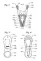
- FIG. 1is an exploded, perspective view of a preferred embodiment of the clip of the instant invention.
- FIG. 2is a cross sectional view of the embodiment of the clip shown in FIG. 1 in the assembled state.
- FIG. 3is a plan view of the outer surface of the jaws of the clip of the instant invention.
- FIG. 4is a plan view of the inner surface of the jaws of the clip of the instant invention.
- FIGS. 1 and 2there is shown an exploded, perspective view of the clip 100 and a cross sectional view of the assembled clip, respectively.
- the clip 100comprises a pair of facing, complementary jaws 101 and 102 with an intermediate bridge 105 connecting the jaws to one another.
- the jawsare connected to bridge 105 by living hinges 106 and 107 .
- arcuate recess 108is formed on the underside of bridge 105 and is suitably configured to receive at least a portion of the periphery of a hanger arm or any other element having a circular (or cylindrical) configuration.
- the angular extent of the arcuate recess 108is somewhat less than 360 degrees.
- the gap in the arcuate recess and the relative flexibility of the segments thereofpermits the recess 108 to releasably grip an external longitudinal support (not shown).
- the arcuate recess 108 of the clip 100prevents the clip from easy disconnection from of the external support even when the clip 100 , per se, is not fully closed.
- a resilient, positioning elementreferred to as spring 150
- spring 150has a generally inverted U-shape and is adapted to be mounted over the bridge 105 and adjacent to the outer surface of jaws 102 and 120 .
- the underside of the base 151 of the spring 150is placed snugly against the upper surface of bridge 105 while the legs 152 and 153 of the spring bear against and engage the outer surfaces of the jaws 102 and 101 , respectively.
- the spring 150is designed to force the lower ends of the jaws 101 and 102 together.
- Each of the jaws 101 and 102is formed of a plastic material which is low cost, lightweight, durable and strong.
- the spring 150is formed of a plastic material which, preferably, exhibits a higher tensile strength and resilience than the material used to fabricate the jaws 102 and 120 .
- the jaws 102 and 120are formed of polypropylene, while the spring 150 is formed of polycarbonate. Of course, other suitable materials can be utilized, if desired.
- each jaw 102 and 120is formed in a substantially planar, generally “figure-8” configuration. While not specifically limited thereto, each jaw includes a relatively large upper end portion 191 or 192 , a narrowed intermediate portion 103 or 104 and a bottom end portion 109 or 110 which is larger than the intermediate portion but smaller than the upper end portion.
- each jawincludes a relatively planar portion 103 or 104 which is co-planar with the inner surface of the respective jaw.
- the upper ends of planar portions 103 and 104are connected to the bridge 105 (shown in cross-section in FIG. 2 ) which extends between the two jaws.
- the planar portions 103 and 104are joined to the opposite ends of the bridge 105 by the respective living hinges 106 and 107 .
- the jaws 101 and 102can freely pivot around the ends of the bridge 105 .
- an elongated recess 112is formed within the outer surface of lower jaw portion 110 .
- a locking recess 114is located at the end of recess 112 of the jaw 102 adjacent to the planar surface portion 104 .
- Locking recess 114is adapted to receive a locking end 154 of the spring 150 (shown best in FIG. 2 ) to secure the two jaws and the spring to each other.
- the jaws 102 and 120are arranged to be disposed face-to-face, with the bridge element 105 forming a connection therebetween.
- the spring 150surrounds a portion of the opposed jaws and bridge 105 so as to maintain the configuration of the clip and to force the bottom ends 109 and 110 of the clip 100 together.
- the spring 150(or resilient bias means) has a generally inverted U-shape having a pair of inwardly flaring legs 152 and 153 joined together by a planar mid-portion 151 .
- Each of the legsterminates at its free end in an enlarged semi-circular projection 154 or 155 which is adapted to be received within a respective one of the locking recesses 113 or 114 in the grooves 111 or 112 in jaws 101 and 102 , respectively.
- FIGS. 3 and 4there are shown the inner and outer surfaces, respectively, of either jaw 101 or 102 .
- the enlarged upper end portion 191 (or 192 ) of the jaw 101 (or 102 )is generally of oval construction and includes an opening 145 (or 146 ).
- the opening 145 (or 146 )is suitably dimensioned so that the leg 153 (or 152 ) of the spring 150 is comfortably received therein, when being assembled with both of the jaws 101 and 102 .
- the outer surface of the end portion 191 (and 192 )includes a pad or cushion 251 seen best in FIG. 2 (or 252 ).
- the pad or cushion 251 (or 252 )is, typically, fabricated of a material such as PTE which is a relatively soft, resilient plastic material.
- the pad 251 (or 252 )is co-molded along with the jaw 101 (and 102 ) on the outer surfaces thereof, respectively.
- the bridge 105is formed integrally with the jaws.
- the pad 251 (or 252 )extends across a substantial portion of the width (or diameter) of the end portion 191 (or 192 ).
- a shallow depressioncan be formed in the end portion 191 (or 192 ) of the jaw 101 (or 102 ) to receive the respective pad 251 (or 252 ).
- the padis, typically, adhered to the jaw by thermal bonding during manufacturing process.
- a portion of the pad 251 (or 252 )can be engaged in an aperture 241 (or 242 ) which passes through the upper end portion 191 (or 192 ) of the jaw.
- the pads 251 (or 252 )increase frictional engagement between the clip and the fingertips of the user but do not harm, snag and/or hurt the user.
- the jaws 101 (and 102 )can be grasped comfortably at the pads or cushions 251 (and 252 ) on the large ends thereof to facilitate the opening of the clip 100 .
- the smaller end portions 181 (and 182 ) of the jaws 101 (and 102 ), respectively,are generally circular in configuration.
- the inner surface of the end portion 109 (or 110 )includes a pad or cushion 201 (or 202 ).
- the pad or cushion 201 (or 202 )is, typically, fabricated of a material such as PTE which is relatively soft, resilient plastic material.
- the pad 201 (or 202 )is co-molded along with the jaws 101 (and 102 ) on the inner surfaces thereof, respectively.
- the pad 201 (or 202 )extends across a substantial portion of the width (or diameter) of the smaller end portion 109 (or 110 ).
- a shallow depression 275 (or 276 ) seen best in FIG. 2can be formed in the end portion 109 (or 110 ) of the jaw 101 (or 102 ) to receive the respective pad 201 (or 202 ).
- the pad 201 (or 202 )is, typically, adhered to the jaw 101 (or 102 by thermal bonding during the manufacturing process.
- the pad 201 (or 120 )is adapted to engage and hold a garment (or other item not shown) securely therebetween under the bias force provided by the spring 150 .
- the pads 201 or 202increase frictional engagement between the clip 100 and the garment or other item but do not harm, snag and/or deface the garment or item.
- gap 191is provided adjacent to the end of leg 152 (or 153 ) in recess 113 (or 114 ) in each jaw member in order to permit the spring 150 to be selectively removed from the jaw members by insertion of a suitable tool between the end of the leg and the end of the groove 111 (or 112 ).
- the pair of jaws 101 and 102are located at opposite ends of the bridge 105 .
- the inverted U-shaped spring 150is slipped over the bridge 105 so that the projections 154 and 155 engage the grooves 111 and 112 in the outer surfaces of the planar portions 103 and 104 of the jaws.
- the spring 150slides toward those ends, with the portions 154 and 155 of the spring sliding along the surfaces of the grooves 111 and 112 until the projections reach the recesses 113 and 114 in the grooves.
- the projections 154 and 155snap into the recesses 113 and 114 , thereby locking the spring 150 in place.
- the spring 150then forces the jaw ends 109 and 110 toward each other. Once the clip components are secured, there is sufficient frictional engagement between the pads 201 and 202 of the jaw ends 109 and 110 for the clip 100 to operate properly. In addition, when attached via the arcuate surface 108 . Clip 100 can be readily slid along an arm of a hanger (or the like) when desired, but is resistant to accidental sliding. Moreover, the clip 100 can be pivoted through an arc of 360 degree about the longitudinal axis of the support which is journalled within the opening of the arcuate recess 108 with minimal likelihood of detachment.
- the opposed end portions 109 and 110 with the co-molded pads 201 and 210form a gripper for the clip 100 which can be opened to receive a garment (or any other item).
- the clip 100is opened by grasping the clip by the upper end portions 191 and 192 of the loops 102 and 120 at the pads 250 and 251 and squeezing those end portions toward each other against the bias force of spring 150 .
- the spring 150forces the lower ends 109 and 110 of the jaws back together to effect the holding of an item tightly between the pads 201 and 202 on the lower jaw ends 109 and 110 .
Landscapes
- Engineering & Computer Science (AREA)
- Textile Engineering (AREA)
- Clamps And Clips (AREA)
Abstract
Description
Claims (18)
Priority Applications (1)
| Application Number | Priority Date | Filing Date | Title |
|---|---|---|---|
| US11/116,582US8201310B1 (en) | 2005-04-29 | 2005-04-29 | Co-molded plastic pinch clip |
Applications Claiming Priority (1)
| Application Number | Priority Date | Filing Date | Title |
|---|---|---|---|
| US11/116,582US8201310B1 (en) | 2005-04-29 | 2005-04-29 | Co-molded plastic pinch clip |
Publications (1)
| Publication Number | Publication Date |
|---|---|
| US8201310B1true US8201310B1 (en) | 2012-06-19 |
Family
ID=46209442
Family Applications (1)
| Application Number | Title | Priority Date | Filing Date |
|---|---|---|---|
| US11/116,582Active2030-05-22US8201310B1 (en) | 2005-04-29 | 2005-04-29 | Co-molded plastic pinch clip |
Country Status (1)
| Country | Link |
|---|---|
| US (1) | US8201310B1 (en) |
Cited By (33)
| Publication number | Priority date | Publication date | Assignee | Title |
|---|---|---|---|---|
| US20100038838A1 (en)* | 2008-08-14 | 2010-02-18 | Gallofornia, Inc. | Sewing clip |
| US20140033509A1 (en)* | 2012-08-01 | 2014-02-06 | Maximum Visibility Solutions, Llc | Advantageous Clamp |
| USD709292S1 (en) | 2013-03-14 | 2014-07-22 | Eric Zeldin | Hanger |
| US20140250640A1 (en)* | 2012-09-20 | 2014-09-11 | 4Jc's Development, Llc | Device for securing an article of clothing |
| ITMI20131611A1 (en)* | 2013-09-30 | 2015-03-31 | Nespoli Group S P A | CLOSURE FOR LAUNDRY |
| US20150219130A1 (en)* | 2013-12-27 | 2015-08-06 | Thomas Killion | Magnetic clip |
| US20150239310A1 (en)* | 2014-02-27 | 2015-08-27 | Timothy Voegeli | Tubeless tire rim clamp assembly |
| US20160008001A1 (en)* | 2013-11-21 | 2016-01-14 | Atricure, Inc. | Occlusion clip |
| US9499318B2 (en) | 2014-08-21 | 2016-11-22 | Cook Medical Technologies Llc | System and method for containment and organization of medical wire |
| US9664213B2 (en) | 2014-08-21 | 2017-05-30 | Cook Medical Technologies Llc | System for containment and organization of medical wire |
| USD821086S1 (en)* | 2016-05-19 | 2018-06-26 | Clover Mfg. Co., Ltd. | Sewing assist clip |
| US20180184830A1 (en)* | 2016-12-30 | 2018-07-05 | Wai Shing Yau | Clip hanger |
| USD845588S1 (en)* | 2018-06-22 | 2019-04-16 | Near the Heart, LLC | Underwire retainer |
| FR3077580A1 (en)* | 2018-02-06 | 2019-08-09 | Laguelle | BRANCH FOR A CLOTHES MACHINE, AND METHOD OF MANUFACTURING SUCH A BRANCH |
| USD870471S1 (en)* | 2018-05-29 | 2019-12-24 | Walmart Apollo, Llc | Garment hanger |
| USD870470S1 (en)* | 2018-05-29 | 2019-12-24 | Walmart Apollo, Llc | Garment hanger |
| USD870472S1 (en)* | 2018-05-29 | 2019-12-24 | Walmart Apollo, Llc | Garment hanger |
| USD878063S1 (en) | 2016-12-30 | 2020-03-17 | Wai Shing Yau | Hanger |
| US10683602B1 (en)* | 2017-11-30 | 2020-06-16 | David Lee Henry | Dual-clip clothespin for clothes-drying system |
| USD902025S1 (en)* | 2019-04-07 | 2020-11-17 | Helen Of Troy Limited | Hook with clip |
| US10959508B1 (en)* | 2020-01-06 | 2021-03-30 | William Phillips | Padded glasses clip apparatus |
| US20220007869A1 (en)* | 2020-07-10 | 2022-01-13 | Matthew Heath Lane | Hanging apparatus with a tension mechanism |
| USD957242S1 (en)* | 2020-05-22 | 2022-07-12 | Crystal Dye | Clip |
| CN114929073A (en)* | 2019-11-07 | 2022-08-19 | 詹娜·哈莉·鲁宾斯坦 | Clothes hanger clamp |
| US20230022282A1 (en)* | 2021-07-20 | 2023-01-26 | Shenzhen Qianhai Patuoxun Network And Technology Co., Ltd. | Clip-on desk lamp |
| US11883035B2 (en) | 2010-10-27 | 2024-01-30 | Atricure, Inc. | Appendage clamp deployment assist device |
| US12004752B2 (en) | 2012-11-21 | 2024-06-11 | Atricure, Inc. | Occlusion clip |
| JP7554018B1 (en) | 2024-06-21 | 2024-09-19 | 日本コパック株式会社 | Clothes hanger and its attachment/detachment member |
| USD1057554S1 (en)* | 2024-07-24 | 2025-01-14 | Mulin Zheng | Magnetic clip |
| US20250031886A1 (en)* | 2023-07-25 | 2025-01-30 | Whitmor, Inc. | Flocked hanger clip |
| USD1064807S1 (en) | 2022-02-02 | 2025-03-04 | Merrick Engineering, Inc. | Clip |
| USD1085454S1 (en)* | 2024-09-06 | 2025-07-22 | Adam Jay Perlin | Toothbrush pinch clip |
| USD1088782S1 (en)* | 2021-09-17 | 2025-08-19 | Kevin Torres | Cork holding device |
Citations (4)
| Publication number | Priority date | Publication date | Assignee | Title |
|---|---|---|---|---|
| US5075935A (en)* | 1990-06-12 | 1991-12-31 | Abdi Abraham M | Garment hanger and clip |
| US5183191A (en)* | 1992-02-06 | 1993-02-02 | Batts, Inc. | Hangers with long lasting non-slip surfaces |
| US5765820A (en)* | 1995-08-17 | 1998-06-16 | Marusiak; Frank | Three-way spring clamp |
| US6842951B1 (en)* | 1998-04-28 | 2005-01-18 | Genprod | Clothes peg |
- 2005
- 2005-04-29USUS11/116,582patent/US8201310B1/enactiveActive
Patent Citations (4)
| Publication number | Priority date | Publication date | Assignee | Title |
|---|---|---|---|---|
| US5075935A (en)* | 1990-06-12 | 1991-12-31 | Abdi Abraham M | Garment hanger and clip |
| US5183191A (en)* | 1992-02-06 | 1993-02-02 | Batts, Inc. | Hangers with long lasting non-slip surfaces |
| US5765820A (en)* | 1995-08-17 | 1998-06-16 | Marusiak; Frank | Three-way spring clamp |
| US6842951B1 (en)* | 1998-04-28 | 2005-01-18 | Genprod | Clothes peg |
Cited By (47)
| Publication number | Priority date | Publication date | Assignee | Title |
|---|---|---|---|---|
| US20100038838A1 (en)* | 2008-08-14 | 2010-02-18 | Gallofornia, Inc. | Sewing clip |
| US8348251B2 (en)* | 2008-08-14 | 2013-01-08 | Paul Edward Gallo | Sewing clip |
| US11883035B2 (en) | 2010-10-27 | 2024-01-30 | Atricure, Inc. | Appendage clamp deployment assist device |
| US20140033509A1 (en)* | 2012-08-01 | 2014-02-06 | Maximum Visibility Solutions, Llc | Advantageous Clamp |
| US20140250640A1 (en)* | 2012-09-20 | 2014-09-11 | 4Jc's Development, Llc | Device for securing an article of clothing |
| US12193680B2 (en) | 2012-11-21 | 2025-01-14 | Atricure, Inc. | Occlusion clip |
| US12004752B2 (en) | 2012-11-21 | 2024-06-11 | Atricure, Inc. | Occlusion clip |
| USD709292S1 (en) | 2013-03-14 | 2014-07-22 | Eric Zeldin | Hanger |
| ITMI20131611A1 (en)* | 2013-09-30 | 2015-03-31 | Nespoli Group S P A | CLOSURE FOR LAUNDRY |
| US20160008001A1 (en)* | 2013-11-21 | 2016-01-14 | Atricure, Inc. | Occlusion clip |
| US11266413B2 (en)* | 2013-11-21 | 2022-03-08 | Atricure, Inc. | Occlusion clip |
| US11998211B2 (en) | 2013-11-21 | 2024-06-04 | Atricure, Inc. | Occlusion clip |
| US11998212B2 (en) | 2013-11-21 | 2024-06-04 | Atricure, Inc. | Occlusion clip |
| US12076019B2 (en) | 2013-11-21 | 2024-09-03 | Atricure, Inc. | Occlusion clip |
| US20150219130A1 (en)* | 2013-12-27 | 2015-08-06 | Thomas Killion | Magnetic clip |
| US10012346B2 (en)* | 2013-12-27 | 2018-07-03 | Thomas Killion | Magnetic clip |
| US9873297B2 (en)* | 2014-02-27 | 2018-01-23 | Timothy Voegeli | Tubeless tire rim clamp assembly |
| US20150239310A1 (en)* | 2014-02-27 | 2015-08-27 | Timothy Voegeli | Tubeless tire rim clamp assembly |
| US10039611B2 (en) | 2014-08-21 | 2018-08-07 | Cook Medical Technologies Llc | System and method for containment and organization of medical wire |
| US10280955B2 (en) | 2014-08-21 | 2019-05-07 | Cook Medical Technologies Llc | System for containment and organization of medical wire |
| US9664213B2 (en) | 2014-08-21 | 2017-05-30 | Cook Medical Technologies Llc | System for containment and organization of medical wire |
| US9499318B2 (en) | 2014-08-21 | 2016-11-22 | Cook Medical Technologies Llc | System and method for containment and organization of medical wire |
| US10646299B2 (en) | 2014-08-21 | 2020-05-12 | Cook Medical Technologies Llc | System and method for containment and organization of medical wire |
| USD821086S1 (en)* | 2016-05-19 | 2018-06-26 | Clover Mfg. Co., Ltd. | Sewing assist clip |
| USD878063S1 (en) | 2016-12-30 | 2020-03-17 | Wai Shing Yau | Hanger |
| US20180184830A1 (en)* | 2016-12-30 | 2018-07-05 | Wai Shing Yau | Clip hanger |
| USD907377S1 (en) | 2016-12-30 | 2021-01-12 | Wai Shing Yau | Hanger |
| USD901909S1 (en) | 2016-12-30 | 2020-11-17 | Wai Shing Yau | Hanger |
| US10683602B1 (en)* | 2017-11-30 | 2020-06-16 | David Lee Henry | Dual-clip clothespin for clothes-drying system |
| FR3077580A1 (en)* | 2018-02-06 | 2019-08-09 | Laguelle | BRANCH FOR A CLOTHES MACHINE, AND METHOD OF MANUFACTURING SUCH A BRANCH |
| USD870472S1 (en)* | 2018-05-29 | 2019-12-24 | Walmart Apollo, Llc | Garment hanger |
| USD870470S1 (en)* | 2018-05-29 | 2019-12-24 | Walmart Apollo, Llc | Garment hanger |
| USD870471S1 (en)* | 2018-05-29 | 2019-12-24 | Walmart Apollo, Llc | Garment hanger |
| USD845588S1 (en)* | 2018-06-22 | 2019-04-16 | Near the Heart, LLC | Underwire retainer |
| USD902025S1 (en)* | 2019-04-07 | 2020-11-17 | Helen Of Troy Limited | Hook with clip |
| CN114929073A (en)* | 2019-11-07 | 2022-08-19 | 詹娜·哈莉·鲁宾斯坦 | Clothes hanger clamp |
| US10959508B1 (en)* | 2020-01-06 | 2021-03-30 | William Phillips | Padded glasses clip apparatus |
| USD957242S1 (en)* | 2020-05-22 | 2022-07-12 | Crystal Dye | Clip |
| US20220007869A1 (en)* | 2020-07-10 | 2022-01-13 | Matthew Heath Lane | Hanging apparatus with a tension mechanism |
| US11766146B2 (en)* | 2020-07-10 | 2023-09-26 | Matthew Heath Lane | Hanging apparatus with a tension mechanism |
| US20230022282A1 (en)* | 2021-07-20 | 2023-01-26 | Shenzhen Qianhai Patuoxun Network And Technology Co., Ltd. | Clip-on desk lamp |
| USD1088782S1 (en)* | 2021-09-17 | 2025-08-19 | Kevin Torres | Cork holding device |
| USD1064807S1 (en) | 2022-02-02 | 2025-03-04 | Merrick Engineering, Inc. | Clip |
| US20250031886A1 (en)* | 2023-07-25 | 2025-01-30 | Whitmor, Inc. | Flocked hanger clip |
| JP7554018B1 (en) | 2024-06-21 | 2024-09-19 | 日本コパック株式会社 | Clothes hanger and its attachment/detachment member |
| USD1057554S1 (en)* | 2024-07-24 | 2025-01-14 | Mulin Zheng | Magnetic clip |
| USD1085454S1 (en)* | 2024-09-06 | 2025-07-22 | Adam Jay Perlin | Toothbrush pinch clip |
Similar Documents
| Publication | Publication Date | Title |
|---|---|---|
| US8201310B1 (en) | Co-molded plastic pinch clip | |
| US20070131238A1 (en) | Hair retaining clip with elastic biasing member | |
| US5402558A (en) | Resilient clip | |
| EP0879005B1 (en) | Spring badge clip | |
| US6979143B2 (en) | Carabiner writing instrument | |
| US9687036B2 (en) | Dress clip | |
| US20030155783A1 (en) | Self-closing bag holder and assembly | |
| US20110289733A1 (en) | Teether/pacifier securing device | |
| US20060219472A1 (en) | Stetoscope holder | |
| EP2995214B1 (en) | Opening implement for accessory catch | |
| AU2003282224B2 (en) | Hairclip | |
| US9717311B2 (en) | Fastening tool | |
| US20040065702A1 (en) | Garment hanger | |
| EP0699043A1 (en) | Garment hanger with pivotable arms | |
| CN205465817U (en) | Fixture structure | |
| KR101616686B1 (en) | A apparatus for fixing accessories | |
| JP7699332B2 (en) | Attachments, clothespins and clothes hangers | |
| JP3726157B2 (en) | Synthetic resin clip | |
| KR200258143Y1 (en) | Clip device for supporting object | |
| JP3183745U (en) | Gripping device and elongate member holding device | |
| JP2015126880A (en) | Mounting brackets that are detachably attached to articles | |
| GB2327866A (en) | Bag carrying handle | |
| CN107435805B (en) | Carry-on article carrying device | |
| KR200274463Y1 (en) | Clip | |
| CA1155428A (en) | Hanger with swivel hook and skirt and trouser clips |
Legal Events
| Date | Code | Title | Description |
|---|---|---|---|
| FEPP | Fee payment procedure | Free format text:PAYOR NUMBER ASSIGNED (ORIGINAL EVENT CODE: ASPN); ENTITY STATUS OF PATENT OWNER: LARGE ENTITY | |
| AS | Assignment | Owner name:MERRICK ENGINEERING, INC., CALIFORNIA Free format text:ASSIGNMENT OF ASSIGNORS INTEREST;ASSIGNORS:ABDI, ABRAHAM;ABDI, MUNA;COULTER, CHARLES L.;REEL/FRAME:028253/0983 Effective date:20050420 | |
| STCF | Information on status: patent grant | Free format text:PATENTED CASE | |
| FPAY | Fee payment | Year of fee payment:4 | |
| MAFP | Maintenance fee payment | Free format text:PAYMENT OF MAINTENANCE FEE, 8TH YEAR, LARGE ENTITY (ORIGINAL EVENT CODE: M1552); ENTITY STATUS OF PATENT OWNER: LARGE ENTITY Year of fee payment:8 | |
| FEPP | Fee payment procedure | Free format text:ENTITY STATUS SET TO SMALL (ORIGINAL EVENT CODE: SMAL); ENTITY STATUS OF PATENT OWNER: SMALL ENTITY | |
| MAFP | Maintenance fee payment | Free format text:PAYMENT OF MAINTENANCE FEE, 12TH YR, SMALL ENTITY (ORIGINAL EVENT CODE: M2553); ENTITY STATUS OF PATENT OWNER: SMALL ENTITY Year of fee payment:12 |