US8201222B2 - Authentication system for authenticating communication terminal - Google Patents
Authentication system for authenticating communication terminalDownload PDFInfo
- Publication number
- US8201222B2 US8201222B2US11/390,079US39007906AUS8201222B2US 8201222 B2US8201222 B2US 8201222B2US 39007906 AUS39007906 AUS 39007906AUS 8201222 B2US8201222 B2US 8201222B2
- Authority
- US
- United States
- Prior art keywords
- communication terminal
- authentication
- state
- predetermined period
- aborted
- Prior art date
- Legal status (The legal status is an assumption and is not a legal conclusion. Google has not performed a legal analysis and makes no representation as to the accuracy of the status listed.)
- Expired - Fee Related, expires
Links
- 238000000034methodMethods0.000claimsabstractdescription60
- 230000008569processEffects0.000claimsabstractdescription58
- 230000007704transitionEffects0.000claimsabstractdescription16
- 230000004044responseEffects0.000claimsdescription14
- 230000010365information processingEffects0.000claimsdescription8
- 238000010586diagramMethods0.000description15
- 230000006870functionEffects0.000description12
- 230000009471actionEffects0.000description3
- 230000008859changeEffects0.000description3
- 230000004913activationEffects0.000description2
- 230000003213activating effectEffects0.000description1
Images


Classifications
- H—ELECTRICITY
- H04—ELECTRIC COMMUNICATION TECHNIQUE
- H04L—TRANSMISSION OF DIGITAL INFORMATION, e.g. TELEGRAPHIC COMMUNICATION
- H04L63/00—Network architectures or network communication protocols for network security
- H04L63/08—Network architectures or network communication protocols for network security for authentication of entities
- H—ELECTRICITY
- H04—ELECTRIC COMMUNICATION TECHNIQUE
- H04W—WIRELESS COMMUNICATION NETWORKS
- H04W12/00—Security arrangements; Authentication; Protecting privacy or anonymity
- H04W12/06—Authentication
- H—ELECTRICITY
- H04—ELECTRIC COMMUNICATION TECHNIQUE
- H04L—TRANSMISSION OF DIGITAL INFORMATION, e.g. TELEGRAPHIC COMMUNICATION
- H04L63/00—Network architectures or network communication protocols for network security
- H04L63/16—Implementing security features at a particular protocol layer
- H04L63/162—Implementing security features at a particular protocol layer at the data link layer
- H—ELECTRICITY
- H04—ELECTRIC COMMUNICATION TECHNIQUE
- H04W—WIRELESS COMMUNICATION NETWORKS
- H04W12/00—Security arrangements; Authentication; Protecting privacy or anonymity
- H04W12/60—Context-dependent security
- H04W12/61—Time-dependent
- H—ELECTRICITY
- H04—ELECTRIC COMMUNICATION TECHNIQUE
- H04W—WIRELESS COMMUNICATION NETWORKS
- H04W52/00—Power management, e.g. Transmission Power Control [TPC] or power classes
- H04W52/02—Power saving arrangements
- H04W52/0209—Power saving arrangements in terminal devices
- H04W52/0251—Power saving arrangements in terminal devices using monitoring of local events, e.g. events related to user activity
- H—ELECTRICITY
- H04—ELECTRIC COMMUNICATION TECHNIQUE
- H04W—WIRELESS COMMUNICATION NETWORKS
- H04W84/00—Network topologies
- H04W84/02—Hierarchically pre-organised networks, e.g. paging networks, cellular networks, WLAN [Wireless Local Area Network] or WLL [Wireless Local Loop]
- H04W84/10—Small scale networks; Flat hierarchical networks
- H04W84/12—WLAN [Wireless Local Area Networks]
- H—ELECTRICITY
- H04—ELECTRIC COMMUNICATION TECHNIQUE
- H04W—WIRELESS COMMUNICATION NETWORKS
- H04W88/00—Devices specially adapted for wireless communication networks, e.g. terminals, base stations or access point devices
- H04W88/02—Terminal devices
- Y—GENERAL TAGGING OF NEW TECHNOLOGICAL DEVELOPMENTS; GENERAL TAGGING OF CROSS-SECTIONAL TECHNOLOGIES SPANNING OVER SEVERAL SECTIONS OF THE IPC; TECHNICAL SUBJECTS COVERED BY FORMER USPC CROSS-REFERENCE ART COLLECTIONS [XRACs] AND DIGESTS
- Y02—TECHNOLOGIES OR APPLICATIONS FOR MITIGATION OR ADAPTATION AGAINST CLIMATE CHANGE
- Y02D—CLIMATE CHANGE MITIGATION TECHNOLOGIES IN INFORMATION AND COMMUNICATION TECHNOLOGIES [ICT], I.E. INFORMATION AND COMMUNICATION TECHNOLOGIES AIMING AT THE REDUCTION OF THEIR OWN ENERGY USE
- Y02D30/00—Reducing energy consumption in communication networks
- Y02D30/70—Reducing energy consumption in communication networks in wireless communication networks
Definitions
- the present inventionrelates to an authentication system for authenticating a supplicant to confirm the legitimacy of the supplicant, and more particularly to an authentication system for authenticating a supplicant again upon elapse of a predetermined period of time after the supplicant has first been authenticated.
- FIG. 1 of the accompanying drawingsis a block diagram of a conventional authentication system. As shown in FIG. 1 , the conventional authentication system has supplicant 90 and authenticator 91 . Authenticator 91 can be connected to RADIUS server 92 .
- Supplicant 90comprises a terminal used by a user, such as a wireless LAN terminal, for example. Supplicant 90 can connect to a network when it is authenticated by authenticator 91 .
- Authenticator 91is an authenticating device such as a wireless LAN access point, and authenticates supplicant 90 serving as a terminal. It is assumed that authenticator 91 uses a RADIUS protocol for authentication, and operates as a RADIUS client. When accessed by supplicant 90 , authenticator 91 exchanges authentication information with RADIUS server 92 . If the authentication is successful, then authenticator 91 sends a successful authentication message to supplicant 90 .
- An authenticationhas an authenticate life time. After supplicant 90 is authenticated, authenticator 91 authenticates supplicant 90 repeatedly at given time intervals.
- RADIUS server 92performs an authentication process for supplicant 90 according to a request from authenticator 91 .
- RADIUS server 92uses a RADIUS protocol for authentication.
- RADIUS server 92receives a request from authenticator 91 which is a RADIUS client, RADIUS server 92 exchanges authentication information with authenticator 91 , and determines whether the authentication is successful or not.
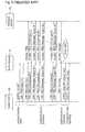
- FIG. 2 of the accompanying drawingsis a sequence diagram of operation of the conventional authentication system.
- supplicant 90sends EAPOL (PPP Extensible Authentication Protocol over Local Area Networks)-Start packet 901 to authenticator 91 .
- EAPOLPPP Extensible Authentication Protocol over Local Area Networks
- authenticator 91When authenticator 91 receives EAPOL-Start packet 901 , authenticator 91 starts an authentication process, and sends EAP-Request packet 902 to supplicant 90 . In response to EAP-Request packet 902 , supplicant 90 sends EAP-response packet 903 to authenticator 91 .
- authenticator 91When authenticator 91 receives EAP-Response packet 903 , authenticator 91 sends Access-Request packet 904 to RADIUS server 92 , requesting RADIUS server 92 to authenticate supplicant 90 . If the authentication subsequently proves to be successful through an authentication sequence, then RADIUS server 92 sends Access-Accept packet 905 indicative of the successful authentication to the authenticator 91 .
- authenticator 91When authenticator 91 receives Access-Accept packet 905 , authenticator 91 sends EAP-Success packet 906 to supplicant 90 , informing supplicant 90 of the successful authentication. Now, supplicant 90 can be connected to a network through authenticator 91 .
- authenticator 91registers the account of supplicant 90 in an internal authentication table (not shown), and starts counting down a reauthentication timer (not shown) corresponding to the account.
- the reauthentication timeris a timer for counting up to an authentication time limit.
- the reauthentication timerexpires, i.e., the period of time in which the previous authentication is valid, or an authenticated period, elapses. Then, authenticator 91 initiates a reauthentication process.
- the reauthentication processis a process for reauthenticating supplicant 90 whose authentication period has elapsed. The reauthentication process will be described below.
- autothenticator 91recognizes that the authenticated period of supplicant 90 has elapsed. Authenticator 91 sends EAP-Request packet 907 to supplicant 90 whose authenticated period has elapsed.
- supplicant 90When supplicant 90 receives EAP-Request packet 907 , supplicant 90 sends EAPOL-Start packet 908 to autothenticator 91 . Subsequently, the authentication system operates in the same manner as with the first authentication cycle.
- autothenticator 91starts an authentication process, and sends EAP-Request packet 909 to supplicant 90 .
- supplicant 90sends EAP-response packet 910 to authenticator 91 .
- authenticator 91When authenticator 91 receives EAP-Response packet 910 , authenticator 91 sends Access-Request packet 911 to RADIUS server 92 , requesting RADIUS server 92 to authenticate supplicant 90 . If the authentication subsequently proves to be successful through an authentication sequence, then RADIUS server 92 sends Access-Accept packet 912 indicative of the successful authentication to the authenticator 91 .
- authenticator 91When authenticator 91 receives Access-Accept packet 912 , authenticator 91 sends EAP-Success packet 913 to supplicant 90 , informing supplicant 90 of the successful authentication. Now, supplicant 90 can be connected to the network through authenticator 91 .
- authenticator 91reregisters the account of supplicant 90 or keeps the account of supplicant 90 registered in the internal authentication table, and resets and starts counting down the reauthentication timer corresponding to the account.
- FIG. 3 of the accompanying drawingsis a sequence diagram showing the first authentication cycle of the conventional authentication system.
- FIG. 3shows in detail the authentication process that is performed by the exchange of packets 901 through 906 shown in FIG. 2 .
- the authentication processis started by the EAPOL-Start packet sent from supplicant 90 to authenticator 91 and the EAP-Request(Identity) sent from authenticator 91 to supplicant 90 .
- FIG. 4 of the accompanying drawingsis a sequence diagram showing the reauthentication cycle of the conventional authentication system.
- FIG. 4shows in detail the authentication process that is performed by the exchange of packets 907 through 913 shown in FIG. 2 .
- the authentication processis started by the EAP-Request(Identity) sent from authenticator 91 to supplicant 90 when the timer expires.
- a successful authentication messageis sent from RADIUS server 92 through authenticator 91 to supplicant 90 , and authenticator 91 resets and starts to count down the reauthentication timer.
- Authenticator 91sends an encryption key to supplicant 90 .
- Supplicant 90may change from an ordinary operational state to a suspended state, a hibernated state, or a shutdown state depending on an operating action made by the user, how the user uses supplicant 90 , or a charged state of the battery thereof.
- Wake-on LANregistered trademark
- Wake-upChanging from the aborted state to the operational state, by way of resumption or activation, is collectively referred to as “wake-up”.
- FIG. 5 of the accompanying drawingsis a view showing a general Wake-on LAN. As shown in FIG. 5 , terminal 93 is connected to network 95 by LAN card 94 , and terminal 96 is also connected to network 95 .
- terminal 93is in the aborted state. Even though terminal 93 is in the aborted state, LAN card 94 remains energized and is linked to network 95 through a MAC layer. When LAN card 94 receives a wake-on packet, it wakes up terminal 93 .
- terminal 96sends a wake-on packet through network 95 to LAN card 94 .
- LAN card 94wakes up terminal 93 .
- the Wake-on LAN functionis performed in the manner described above.
- supplicant 90 in the authentication system shown in FIG. 1is in the aborted state, supplicant 90 is unable to receive packets from authenticator 91 until supplicant 90 is waked up.
- authenticator 91starts an authentication cycle.
- supplicant 90cannot perform the authentication process, the authentication fails.
- the link that supplicant 90 has to the networkis disconnected, and supplicant 90 cannot be waked up by another terminal (not shown) according to the Wake-on LAN function.
- an authentication systemrepeatedly performs an authentication process each time a predetermined period of effective authentication elapses.
- the authentication systemhas a communication terminal and an authentication device.
- the communication terminalis connectable to a network when an authentication thereof is successful, changes between an operational state and an aborted state, and indicates a transition to the aborted state when the communication terminal changes from the operational state to the aborted state.
- the authentication devicerepeatedly performs the authentication process, counts the predetermined period for the communication terminal when the authentication thereof is successful, and performs the authentication process again for the communication terminal if the predetermined period elapses.
- the authentication devicestops counting the predetermined period for the communication terminal and keeps the authentication of the communication terminal in a previous authentication cycle effective.
- the communication terminalWhen the communication terminal changes from the state in which the authentication thereof has been successful to the aborted state, the communication terminal indicates the transition to the aborted state to the authentication device, and the authentication device temporarily stops counting the predetermined period, or an authenticated period, for the communication terminal from which the transition to the aborted state is indicated. Therefore, the authenticated period of the communication terminal in the aborted state does not expire, and packets can be sent to the communication terminal.
- FIG. 1is a block diagram of a conventional authentication system
- FIG. 2is a sequence diagram of operation of the conventional authentication system
- FIG. 3is a sequence diagram showing a first authentication cycle of the conventional authentication system
- FIG. 4is a sequence diagram showing a reauthentication cycle of the conventional authentication system
- FIG. 5is a view showing a general Wake-on LAN
- FIG. 6is a block diagram of an authentication system according to an embodiment of the present invention.
- FIG. 7is a block diagram of a supplicant of the authentication system shown in FIG. 6 ;
- FIG. 8is a block diagram of an authenticator of the authentication system shown in FIG. 6 ;
- FIG. 9is a flowchart of an operation sequence of the authenticator with respect to a WOL-RDY flag and a reauthentication timer;
- FIG. 10is a sequence diagram of operation of the authentication system according to the embodiment of the present invention.
- FIG. 11is a sequence diagram of a sequence from an aborted state to a successful authentication in the authentication system according to the embodiment of the present invention.
- FIG. 6shows in block form an authentication system according to an embodiment of the present invention.
- the authentication systemhas supplicant 10 and authenticator 11 .
- Authenticator 11can be connected to RADIUS server 12 .
- Supplicant 10has a function to connect to a LAN, e.g., a LAN card, and comprises a user terminal capable of connecting to a network, e.g., a wireless LAN terminal. Supplicant 10 can connect to a network when it is authenticated by authenticator 11 .
- Supplicant 10also has a function to change from an ordinary operational state to a suspended state, a hibernated state, or a shutdown state depending on an operating action made by the user, how the user uses supplicant 90 , or a charged state of the battery thereof.
- the suspended stateis a state in which a program being executed by supplicant 10 is temporarily suspended.
- the hibernated stateis a state in which the data in a main memory is stored into a hard disk and supplicant 10 enters an energy-saving mode.
- the shutdown stateis a state in which a program being executed by supplicant 10 is terminated and supplicant 10 is turned off. All of the suspended state, the hibernated state, and the shutdown state are collectively referred to as “aborted state”.
- Supplicant 10which is in the aborted state is resumed or activated by an instruction sent from another computer through a network. This is a function known as Wake-on LAN. Changing from the aborted state to the operational state, by way of resumption or activation, is collectively referred to as “wake-up”. Once supplicant 10 is connected to a network based on a successful authentication, then even if supplicant 10 subsequently enters the aborted state, its function to connect to a LAN remains active, and supplicant 10 wakes up when it receives a wake-on packet.
- supplicant 10When supplicant 10 is about to enter the aborted state, supplicant 10 notifies authenticator 11 of its being in the aborted state.
- the aborted stateis indicated by a WOL-RDY packet.
- supplicant 10wakes up from the aborted state, it operates in the same manner as with the first authentication cycle.
- Authenticator 11is an authenticating device such as a wireless LAN access point, and authenticates supplicant 10 serving as a terminal. It is assumed that authenticator 11 uses a RADIUS protocol for authentication, and operates as a RADIUS client. When accessed by supplicant 10 , authenticator 11 exchanges authentication information with RADIUS server 12 . If the authentication is successful, then authenticator 11 sends a successful authentication message to supplicant 10 .
- An authenticationhas an authenticate life time. After supplicant 10 is authenticated, authenticator 11 authenticates supplicant 10 repeatedly at given time intervals. If, however, supplicant 10 is in the aborted state, then authenticator 11 stops counting down a timer for supplicant 10 .
- authenticator 11manages a reauthentication timer for measuring the elapse of an authenticated period and a WOL-RDY flag indicative of whether supplicant 10 is in the aborted state or not, with respect to the account of supplicant 10 .
- authenticator 11When authenticator 11 receives a WOL-RDY packet from supplicant 10 , authenticator 11 sets the WOL-RDY flag of supplicant 10 to “1” representing the aborted state. When an authentication process is initiated from supplicant 10 , authenticator 11 resets the WOL-RDY flag to “0” representing an unaborted state.
- the reauthentication timeris a timer which expires when it counts down to zero a predetermined period of time representing an authenticated period. If the WOL-RDY flag is “1”, then authenticator 11 stops counting down the reauthentication timer.
- authenticator 11When the reauthentication timer expires, authenticator 11 starts an authentication process. Each time the authentication is successful, authenticator 11 resets the reauthentication timer.
- RADIUS server 12performs an authentication process for supplicant 10 according to a request from authenticator 11 .
- RADIUS server 12uses a RADIUS protocol for authentication.
- RADIUS server 12receives a request from authenticator 11 which is a RADIUS client, RADIUS server 12 exchanges authentication information with authenticator 11 , and determines whether the authentication is successful or not.
- FIG. 7shows in block form supplicant 10 of the authentication system shown in FIG. 6 .
- supplicant 10has communication function unit 21 , information processor 22 , and aborted state manager 23 .
- Communication function unit 21connects to a network and sends packets to and receives packets from the network.
- communication function unit 21instructs aborted state manager 23 to change to the operational state. Even when information processor 22 is in the aborted state, communication function unit 21 continues to operate and remains capable of receiving a wake-on packet.
- Information processor 22performs various information processing processes as desired by the user. When communication function unit 21 connects to a network, information processor 22 performs an authentication process in cooperation with authenticator 11 . If there is an authentication request from authenticator 11 , information processor 22 performs an authentication process again.
- information processor 22stops its information processing processes, and enters an aborted state such as a suspended state, a hibernated state, or a shutdown state.
- information processor 22enters the aborted state, it sends a WOL-RDY packet to authenticator 11 , informing authenticator 11 of its being in the aborted state.
- information processor 22When information processor 22 is waked up from the aborted state by an instruction from aborted state manager 23 , information processor 22 performs an authentication cycle which is the same as the first authentication cycle.
- Aborted state manager 23manages transitions between the operational state and the aborted state. Aborted state manager 23 determines whether supplicant 10 should be brought into the aborted state or not based on an operating action made by the user, how the user uses supplicant 10 , or a charged state of the battery thereof. When aborted state manager 23 is informed of the reception of a wake-on packet by communication function unit 21 , aborted state manager 23 cancels the aborted state, and wakes up information processor 22 .
- FIG. 8shows in block form authenticator 11 of the authentication system shown in FIG. 6 .
- authenticator 11has authentication processor 31 , timer manager 32 , flag manager 33 , and authentication table 34 .
- Authentication processor 31performs an authentication process in response to an authentication start request from supplicant 10 or an indication of timer expiration from timer manager 32 .
- authentication processor 31exchanges authentication information with supplicant 10 and RADIUS server 12 .
- a first authentication cycleis initiated by a request from supplicant 10 . If the first authentication cycle is successful, then authentication processor 31 sets a WOL-FDY flag and a reauthentication timer for the account of supplicant 10 . Supplicant 10 , the WOL-FDY flag, and the reauthentication timer are associated with each other in authentication table 34 .
- a subsequent authentication cycleis started by a notification from timer manager 32 .
- Timer manager 32manages the counting of a reauthentication timer corresponding to the account of supplicant 10 whose first authentication cycle has been made successful by authentication processor 31 . If the WOL-RDY flag of supplicant 10 is set to “1” (aborted state) by flag manager 33 , then timer manager 32 temporarily stops counting down the reauthentication timer for supplicant 10 . If the WOL-RDY flag of supplicant 10 is reset to “0” (unaborted state), then timer manager 32 resumes counting down the reauthentication timer for supplicant 10 .
- timer manager 32informs authentication processor 31 of the timer expiration. If authentication processor 31 thus informed is successful in authenticating supplicant 10 , then timer manager 33 resets the reauthentication timer for supplicant 10 , and starts counting down the reauthentication timer from an initial timer value.
- Flag manager 33manages the WOL-RDY flag of supplicant 10 which has been successfully authenticated by authentication processor 31 . Initially, the WOL-RDY flag is of a value “0”. When flag manager 33 receives a WOL-RDY packet from supplicant 10 , flag manager 33 sets the WOL-RDY flag to “1”. When flag manager 33 is requested by supplicant 10 to start an authentication process, flag manager 33 sets the WOL-RDY flag to “0”. A request to start an authentication process from supplicant 10 is determined based on an EAPOL (PPP Extensible Authentication Protocol over Local Area Networks)-Start packet.
- EAPOLPPPExtensible Authentication Protocol over Local Area Networks
- FIG. 9is a flowchart of an operation sequence of authenticator 11 with respect to the WOL-RDY flag and the reauthentication timer. As shown in FIG. 9 , if authenticator 11 is successful in a first authentication cycle, then authenticator 11 resets the WOL-RDY flag to the initial value of “0”, starting to count down the reauthentication timer in step 101 .
- authenticator 11determines whether it has received a WOL-RDY packet from supplicant 10 or not in step 102 . If authenticator 11 has not received a WOL-RDY packet, then authenticator 11 repeats step 102 .
- authenticator 11If authenticator 11 has received a WOL-RDY packet, then authenticator 11 sets the WOL-RDY flag to “1” and temporarily stops counting down the reauthentication timer in step 103 . Then, authenticator 11 determines whether it has received an EAPOL-Start packet from supplicant 10 or not in step 104 . If authenticator 11 has not received an EAPOL-Start packet, then authenticator 11 repeats step 104 .
- authenticator 11If authenticator 11 has received an EAPOL-Start packet, then authenticator 11 performs an authentication cycle which is the same as the first authentication cycle. Control goes back to step S 101 , resetting the WOL-RDY flag to “0” and starting to count down the reauthentication timer.
- FIG. 10is a sequence diagram of operation of the authentication system according to the embodiment of the present invention. As shown in FIG. 10 , supplicant 10 sends EAPOL-Start packet 201 to authenticator 11 in a first authentication cycle.
- authenticator 11When authenticator 11 receives EAPOL-Start packet 201 , authenticator 11 starts an authentication process, and sends EAP-Request packet 202 to supplicant 10 . In response to EAP-Request packet 202 , supplicant 10 sends EAP-response packet 203 to authenticator 11 .
- authenticator 11When authenticator 11 receives EAP-Response packet 203 , authenticator 11 sends Access-Request packet 204 to RADIUS server 12 , requesting RADIUS server 12 to authenticate supplicant 10 . If the authentication subsequently proves to be successful through an authentication sequence, then RADIUS server 12 sends Access-Accept packet 205 indicative of the successful authentication to the authenticator 11 .
- authenticator 11When authenticator 11 receives Access-Accept packet 205 , authenticator 11 sends EAP-Success packet 206 to supplicant 10 , informing supplicant 10 of the successful authentication. Now, supplicant 10 can be connected to a network through authenticator 11 .
- authenticator 11registers the account of supplicant 10 in internal authentication table 34 , and starts counting down the reauthentication timer corresponding to the account.
- WOL-RDY packet 207includes identification information for identifying the account of supplicant 10 .
- authenticator 11sets a WOL-RDY flag of supplicant 10 which has been identified based on the identification information, to “1”, and temporarily stops counting down the reauthentication timer. Therefore, the authenticated period does not expire while supplicant 10 is in the aborted state.
- supplicant 10is subsequently waked up according to the Wake-on LAN function by another computer (not shown) on a network (not shown). Since the authenticated period has not expired, wake-on packet 208 from the other computer reaches supplicant 10 through authenticator 11 .
- supplicant 10When supplicant 10 receives wake-on packet 208 , supplicant 10 is waked up into the operational state, and sends EAPOL-Start packet 209 to authenticator 11 as in the first authentication cycle, when authenticator 11 receives EAPOL-Start packet 209 , authenticator 11 recognizes the cancellation of the aborted state, resets the WOL-RDY flag to “0”, and resumes counting down the reauthentication timer.
- Authenticator 11starts performing an authentication cycle which is the same as the first authentication cycle, and sends EAP-Request packet 210 to supplicant 10 .
- supplicant 10receives EAP-Request packet 210
- supplicant 10sends EAP-response packet 211 to authenticator 11 .
- authenticator 11When authenticator 11 receives EAP-Response packet 211 , authenticator 11 sends Access-Request packet 212 to RADIUS server 12 , requesting RADIUS server 12 to authenticate supplicant 10 . If the authentication subsequently proves to be successful through an authentication sequence, then RADIUS server 12 sends Access-Accept packet 213 indicative of the successful authentication to the authenticator 11 .
- authenticator 11When authenticator 11 receives Access-Accept packet 213 , authenticator 11 sends EAP-Success packet 214 to supplicant 10 , informing supplicant 10 of the successful authentication. Now, supplicant 10 can be connected to a network through authenticator 11 .
- FIG. 11is a sequence diagram of a sequence from the aborted state to the successful authentication in the authentication system according to the embodiment of the present invention.
- FIG. 11shows in detail the authentication process that is performed by the exchange of packets 207 through 213 shown in FIG. 10 .
- supplicant 10enters the aborted state
- supplicant 10sends a WOL-RDY packet to authenticator 11 , which then temporarily stops counting down the reauthentication timer.
- supplicant 10is waked up by the occurrence of a certain event such as the reception of a wake-up packet or the like, and sends an EAPOL-Start packet to authenticator 11 .
- the authentication processis started by the EAPOL-Start packet sent from supplicant 10 to authenticator 11 and the EAP-Request(Identity) sent from authenticator 11 to supplicant 10 .
- Challenge packetsare repeatedly sent from RADIUS server 12 to supplicant 10 and Message Digest packets are repeatedly sent from supplicant 10 to RADIUS server 12 as responses to the Challenge packets.
- the successful authenticationis indicated from RADIUS server 12 through authenticator 11 to supplicant 10 , and the reauthentication timer of authenticator 11 starts to count down.
- Authenticator 11sends an encryption key to supplicant 10 .
- supplicant 10when supplicant 10 changes from the state in which the authentication is successful and supplicant 10 is connected to the network to the aborted state, supplicant 10 indicates the state transition to authenticator 11 with a WOL-RDY packet.
- Authenticator 11temporarily stops counting down the authenticated period for supplicant 10 from which the transition to the aborted state has been indicated.
- authenticator 11performs an authentication process. If the authentication is successful, then authenticator 11 starts to count down the authenticated period of supplicant 10 from an initial value. Consequently, the authenticated period of supplicant 10 that is in the aborted state does not expire, and another computer can send packets to supplicant 10 in the aborted state through the network.
- another computercan send a wake-on packet to supplicant 10 in the aborted state to wake up supplicant 10 .
Landscapes
- Engineering & Computer Science (AREA)
- Computer Security & Cryptography (AREA)
- Computer Networks & Wireless Communication (AREA)
- Signal Processing (AREA)
- Computer Hardware Design (AREA)
- Computing Systems (AREA)
- General Engineering & Computer Science (AREA)
- Mobile Radio Communication Systems (AREA)
Abstract
Description
Claims (14)
Applications Claiming Priority (2)
| Application Number | Priority Date | Filing Date | Title |
|---|---|---|---|
| JP2005101936AJP4679205B2 (en) | 2005-03-31 | 2005-03-31 | Authentication system, apparatus, method, program, and communication terminal |
| JP2005-101936 | 2005-03-31 |
Publications (2)
| Publication Number | Publication Date |
|---|---|
| US20060225129A1 US20060225129A1 (en) | 2006-10-05 |
| US8201222B2true US8201222B2 (en) | 2012-06-12 |
Family
ID=37072186
Family Applications (1)
| Application Number | Title | Priority Date | Filing Date |
|---|---|---|---|
| US11/390,079Expired - Fee RelatedUS8201222B2 (en) | 2005-03-31 | 2006-03-28 | Authentication system for authenticating communication terminal |
Country Status (2)
| Country | Link |
|---|---|
| US (1) | US8201222B2 (en) |
| JP (1) | JP4679205B2 (en) |
Cited By (28)
| Publication number | Priority date | Publication date | Assignee | Title |
|---|---|---|---|---|
| US10262324B2 (en) | 2010-11-29 | 2019-04-16 | Biocatch Ltd. | System, device, and method of differentiating among users based on user-specific page navigation sequence |
| US10298614B2 (en)* | 2010-11-29 | 2019-05-21 | Biocatch Ltd. | System, device, and method of generating and managing behavioral biometric cookies |
| US10397262B2 (en) | 2017-07-20 | 2019-08-27 | Biocatch Ltd. | Device, system, and method of detecting overlay malware |
| US10404729B2 (en) | 2010-11-29 | 2019-09-03 | Biocatch Ltd. | Device, method, and system of generating fraud-alerts for cyber-attacks |
| US10476873B2 (en)* | 2010-11-29 | 2019-11-12 | Biocatch Ltd. | Device, system, and method of password-less user authentication and password-less detection of user identity |
| US10474815B2 (en) | 2010-11-29 | 2019-11-12 | Biocatch Ltd. | System, device, and method of detecting malicious automatic script and code injection |
| US10523680B2 (en) | 2015-07-09 | 2019-12-31 | Biocatch Ltd. | System, device, and method for detecting a proxy server |
| US10579784B2 (en) | 2016-11-02 | 2020-03-03 | Biocatch Ltd. | System, device, and method of secure utilization of fingerprints for user authentication |
| US10586036B2 (en) | 2010-11-29 | 2020-03-10 | Biocatch Ltd. | System, device, and method of recovery and resetting of user authentication factor |
| US10621585B2 (en) | 2010-11-29 | 2020-04-14 | Biocatch Ltd. | Contextual mapping of web-pages, and generation of fraud-relatedness score-values |
| US10685355B2 (en) | 2016-12-04 | 2020-06-16 | Biocatch Ltd. | Method, device, and system of detecting mule accounts and accounts used for money laundering |
| US10719765B2 (en) | 2015-06-25 | 2020-07-21 | Biocatch Ltd. | Conditional behavioral biometrics |
| US10728761B2 (en) | 2010-11-29 | 2020-07-28 | Biocatch Ltd. | Method, device, and system of detecting a lie of a user who inputs data |
| US10747305B2 (en) | 2010-11-29 | 2020-08-18 | Biocatch Ltd. | Method, system, and device of authenticating identity of a user of an electronic device |
| US10776476B2 (en) | 2010-11-29 | 2020-09-15 | Biocatch Ltd. | System, device, and method of visual login |
| US10834590B2 (en) | 2010-11-29 | 2020-11-10 | Biocatch Ltd. | Method, device, and system of differentiating between a cyber-attacker and a legitimate user |
| US10897482B2 (en) | 2010-11-29 | 2021-01-19 | Biocatch Ltd. | Method, device, and system of back-coloring, forward-coloring, and fraud detection |
| US10917431B2 (en)* | 2010-11-29 | 2021-02-09 | Biocatch Ltd. | System, method, and device of authenticating a user based on selfie image or selfie video |
| US10949757B2 (en) | 2010-11-29 | 2021-03-16 | Biocatch Ltd. | System, device, and method of detecting user identity based on motor-control loop model |
| US10949514B2 (en) | 2010-11-29 | 2021-03-16 | Biocatch Ltd. | Device, system, and method of differentiating among users based on detection of hardware components |
| US10970394B2 (en) | 2017-11-21 | 2021-04-06 | Biocatch Ltd. | System, device, and method of detecting vishing attacks |
| US11055395B2 (en) | 2016-07-08 | 2021-07-06 | Biocatch Ltd. | Step-up authentication |
| US20210329030A1 (en)* | 2010-11-29 | 2021-10-21 | Biocatch Ltd. | Device, System, and Method of Detecting Vishing Attacks |
| US11210674B2 (en) | 2010-11-29 | 2021-12-28 | Biocatch Ltd. | Method, device, and system of detecting mule accounts and accounts used for money laundering |
| US11223619B2 (en) | 2010-11-29 | 2022-01-11 | Biocatch Ltd. | Device, system, and method of user authentication based on user-specific characteristics of task performance |
| US11269977B2 (en) | 2010-11-29 | 2022-03-08 | Biocatch Ltd. | System, apparatus, and method of collecting and processing data in electronic devices |
| US11606353B2 (en) | 2021-07-22 | 2023-03-14 | Biocatch Ltd. | System, device, and method of generating and utilizing one-time passwords |
| US20240080339A1 (en)* | 2010-11-29 | 2024-03-07 | Biocatch Ltd. | Device, System, and Method of Detecting Vishing Attacks |
Families Citing this family (11)
| Publication number | Priority date | Publication date | Assignee | Title |
|---|---|---|---|---|
| US20080184332A1 (en)* | 2007-01-31 | 2008-07-31 | Motorola, Inc. | Method and device for dual authentication of a networking device and a supplicant device |
| JP5328141B2 (en)* | 2007-12-05 | 2013-10-30 | キヤノン株式会社 | COMMUNICATION DEVICE, COMMUNICATION DEVICE CONTROL METHOD, COMPUTER PROGRAM |
| US7940696B2 (en)* | 2007-12-20 | 2011-05-10 | International Business Macines Corporation | Remotely booting computing nodes in a switching domain |
| JP5270937B2 (en) | 2008-03-17 | 2013-08-21 | キヤノン株式会社 | COMMUNICATION DEVICE AND ITS CONTROL METHOD |
| JP4618344B2 (en)* | 2008-07-29 | 2011-01-26 | コニカミノルタビジネステクノロジーズ株式会社 | Authentication device, authentication system, authentication method, authentication program, and recording medium |
| CN102137401B (en)* | 2010-12-09 | 2018-07-20 | 华为技术有限公司 | WLAN centralization 802.1X authentication methods and device and system |
| JP6202647B1 (en)* | 2016-05-20 | 2017-09-27 | Necプラットフォームズ株式会社 | Terminal device, communication device, authentication system, and authentication program |
| US10884474B2 (en)* | 2018-07-19 | 2021-01-05 | Hewlett Packard Enterprise Development Lp | Method for managing non-chatty IoT devices to remain in an authenticated state |
| US11394702B2 (en)* | 2019-09-23 | 2022-07-19 | T-Mobile Usa, Inc. | Authentication system when authentication is not functioning |
| US11882110B2 (en)* | 2020-04-29 | 2024-01-23 | Hewlett Packard Enterprise Development Lp | Renewal of security certificates of supplicants |
| KR20230154720A (en)* | 2022-05-02 | 2023-11-09 | 삼성전자주식회사 | Electronic device and method for authentication in session initiation protocol |
Citations (11)
| Publication number | Priority date | Publication date | Assignee | Title |
|---|---|---|---|---|
| JPH1185326A (en) | 1997-09-04 | 1999-03-30 | Internatl Business Mach Corp <Ibm> | Extended unit for information processing system, information processing system mounted on extended unit, and control method for information processing system |
| JP2002044177A (en) | 2000-07-19 | 2002-02-08 | Pfu Ltd | Device power remote management method, device power remote management system, and recording medium |
| JP2003224577A (en) | 2001-10-05 | 2003-08-08 | Toyo Commun Equip Co Ltd | Internet repeater |
| JP2003259417A (en) | 2002-03-06 | 2003-09-12 | Nec Corp | Radio lan system and access control method employing it |
| US20060168198A1 (en)* | 2005-01-26 | 2006-07-27 | Inventec Corporation | Web page browsing timer and method thereof |
| US20070008937A1 (en)* | 2003-07-22 | 2007-01-11 | Thomson Licensing S.A. | Method and apparatus for controlling credit based access (prepaid) to a wireless network |
| US20070230453A1 (en)* | 2004-02-06 | 2007-10-04 | Telecom Italia S.P.A. | Method and System for the Secure and Transparent Provision of Mobile Ip Services in an Aaa Environment |
| US20070280207A1 (en)* | 2004-03-03 | 2007-12-06 | Mitsubishi Electric Corporation | Layer 2 Switch Network System |
| US20070289011A1 (en)* | 2003-12-23 | 2007-12-13 | Symbian Software Limited | Method for Secure Operation a Computing Device |
| US7350077B2 (en)* | 2002-11-26 | 2008-03-25 | Cisco Technology, Inc. | 802.11 using a compressed reassociation exchange to facilitate fast handoff |
| US7434258B2 (en)* | 2002-05-07 | 2008-10-07 | Nokia Corporation | Method and communication system for controlling security association lifetime |
Family Cites Families (7)
| Publication number | Priority date | Publication date | Assignee | Title |
|---|---|---|---|---|
| JP3016524B2 (en)* | 1991-06-27 | 2000-03-06 | 株式会社東芝 | Recording device |
| JPH1079733A (en)* | 1996-09-03 | 1998-03-24 | Kokusai Denshin Denwa Co Ltd <Kdd> | Authentication method and authentication system using IC card |
| JP2000003336A (en)* | 1998-06-16 | 2000-01-07 | Nec Corp | User authentication method and user authentication system in portable data communication terminal device |
| JP2000187645A (en)* | 1998-12-22 | 2000-07-04 | Fujitsu Ltd | Information providing system and method |
| JP3944089B2 (en)* | 2003-01-31 | 2007-07-11 | 株式会社東芝 | Authentication processing system, terminal authentication device, authentication processing method, and authentication processing program |
| JP2006031097A (en)* | 2004-07-12 | 2006-02-02 | Matsushita Electric Ind Co Ltd | Communication system and communication terminal used therefor, authentication information management method, authentication information management program, and recording medium for storing authentication information management program |
| JP4568857B2 (en)* | 2004-12-24 | 2010-10-27 | 富士通テレコムネットワークス株式会社 | Authentication transmission system |
- 2005
- 2005-03-31JPJP2005101936Apatent/JP4679205B2/ennot_activeExpired - Fee Related
- 2006
- 2006-03-28USUS11/390,079patent/US8201222B2/ennot_activeExpired - Fee Related
Patent Citations (12)
| Publication number | Priority date | Publication date | Assignee | Title |
|---|---|---|---|---|
| JPH1185326A (en) | 1997-09-04 | 1999-03-30 | Internatl Business Mach Corp <Ibm> | Extended unit for information processing system, information processing system mounted on extended unit, and control method for information processing system |
| US6421782B1 (en) | 1997-09-04 | 2002-07-16 | International Business Machines Corporation | Expansion unit for differentiating wake-up packets received in an information processing system |
| JP2002044177A (en) | 2000-07-19 | 2002-02-08 | Pfu Ltd | Device power remote management method, device power remote management system, and recording medium |
| JP2003224577A (en) | 2001-10-05 | 2003-08-08 | Toyo Commun Equip Co Ltd | Internet repeater |
| JP2003259417A (en) | 2002-03-06 | 2003-09-12 | Nec Corp | Radio lan system and access control method employing it |
| US7434258B2 (en)* | 2002-05-07 | 2008-10-07 | Nokia Corporation | Method and communication system for controlling security association lifetime |
| US7350077B2 (en)* | 2002-11-26 | 2008-03-25 | Cisco Technology, Inc. | 802.11 using a compressed reassociation exchange to facilitate fast handoff |
| US20070008937A1 (en)* | 2003-07-22 | 2007-01-11 | Thomson Licensing S.A. | Method and apparatus for controlling credit based access (prepaid) to a wireless network |
| US20070289011A1 (en)* | 2003-12-23 | 2007-12-13 | Symbian Software Limited | Method for Secure Operation a Computing Device |
| US20070230453A1 (en)* | 2004-02-06 | 2007-10-04 | Telecom Italia S.P.A. | Method and System for the Secure and Transparent Provision of Mobile Ip Services in an Aaa Environment |
| US20070280207A1 (en)* | 2004-03-03 | 2007-12-06 | Mitsubishi Electric Corporation | Layer 2 Switch Network System |
| US20060168198A1 (en)* | 2005-01-26 | 2006-07-27 | Inventec Corporation | Web page browsing timer and method thereof |
Cited By (40)
| Publication number | Priority date | Publication date | Assignee | Title |
|---|---|---|---|---|
| US11314849B2 (en) | 2010-11-29 | 2022-04-26 | Biocatch Ltd. | Method, device, and system of detecting a lie of a user who inputs data |
| US11269977B2 (en) | 2010-11-29 | 2022-03-08 | Biocatch Ltd. | System, apparatus, and method of collecting and processing data in electronic devices |
| US12101354B2 (en)* | 2010-11-29 | 2024-09-24 | Biocatch Ltd. | Device, system, and method of detecting vishing attacks |
| US10404729B2 (en) | 2010-11-29 | 2019-09-03 | Biocatch Ltd. | Device, method, and system of generating fraud-alerts for cyber-attacks |
| US10476873B2 (en)* | 2010-11-29 | 2019-11-12 | Biocatch Ltd. | Device, system, and method of password-less user authentication and password-less detection of user identity |
| US10474815B2 (en) | 2010-11-29 | 2019-11-12 | Biocatch Ltd. | System, device, and method of detecting malicious automatic script and code injection |
| US20240080339A1 (en)* | 2010-11-29 | 2024-03-07 | Biocatch Ltd. | Device, System, and Method of Detecting Vishing Attacks |
| US11838118B2 (en)* | 2010-11-29 | 2023-12-05 | Biocatch Ltd. | Device, system, and method of detecting vishing attacks |
| US10586036B2 (en) | 2010-11-29 | 2020-03-10 | Biocatch Ltd. | System, device, and method of recovery and resetting of user authentication factor |
| US10621585B2 (en) | 2010-11-29 | 2020-04-14 | Biocatch Ltd. | Contextual mapping of web-pages, and generation of fraud-relatedness score-values |
| US11736478B2 (en)* | 2010-11-29 | 2023-08-22 | Biocatch Ltd. | Device, system, and method of user authentication based on user-specific characteristics of task performance |
| US11580553B2 (en) | 2010-11-29 | 2023-02-14 | Biocatch Ltd. | Method, device, and system of detecting mule accounts and accounts used for money laundering |
| US10728761B2 (en) | 2010-11-29 | 2020-07-28 | Biocatch Ltd. | Method, device, and system of detecting a lie of a user who inputs data |
| US10747305B2 (en) | 2010-11-29 | 2020-08-18 | Biocatch Ltd. | Method, system, and device of authenticating identity of a user of an electronic device |
| US10949757B2 (en) | 2010-11-29 | 2021-03-16 | Biocatch Ltd. | System, device, and method of detecting user identity based on motor-control loop model |
| US11425563B2 (en) | 2010-11-29 | 2022-08-23 | Biocatch Ltd. | Method, device, and system of differentiating between a cyber-attacker and a legitimate user |
| US10834590B2 (en) | 2010-11-29 | 2020-11-10 | Biocatch Ltd. | Method, device, and system of differentiating between a cyber-attacker and a legitimate user |
| US10897482B2 (en) | 2010-11-29 | 2021-01-19 | Biocatch Ltd. | Method, device, and system of back-coloring, forward-coloring, and fraud detection |
| US10298614B2 (en)* | 2010-11-29 | 2019-05-21 | Biocatch Ltd. | System, device, and method of generating and managing behavioral biometric cookies |
| US10776476B2 (en) | 2010-11-29 | 2020-09-15 | Biocatch Ltd. | System, device, and method of visual login |
| US11223619B2 (en) | 2010-11-29 | 2022-01-11 | Biocatch Ltd. | Device, system, and method of user authentication based on user-specific characteristics of task performance |
| US11330012B2 (en) | 2010-11-29 | 2022-05-10 | Biocatch Ltd. | System, method, and device of authenticating a user based on selfie image or selfie video |
| US10262324B2 (en) | 2010-11-29 | 2019-04-16 | Biocatch Ltd. | System, device, and method of differentiating among users based on user-specific page navigation sequence |
| US20210329030A1 (en)* | 2010-11-29 | 2021-10-21 | Biocatch Ltd. | Device, System, and Method of Detecting Vishing Attacks |
| US11210674B2 (en) | 2010-11-29 | 2021-12-28 | Biocatch Ltd. | Method, device, and system of detecting mule accounts and accounts used for money laundering |
| US10949514B2 (en) | 2010-11-29 | 2021-03-16 | Biocatch Ltd. | Device, system, and method of differentiating among users based on detection of hardware components |
| US20220116389A1 (en)* | 2010-11-29 | 2022-04-14 | Biocatch Ltd. | Device, system, and method of user authentication based on user-specific characteristics of task performance |
| US11250435B2 (en) | 2010-11-29 | 2022-02-15 | Biocatch Ltd. | Contextual mapping of web-pages, and generation of fraud-relatedness score-values |
| US10917431B2 (en)* | 2010-11-29 | 2021-02-09 | Biocatch Ltd. | System, method, and device of authenticating a user based on selfie image or selfie video |
| US11238349B2 (en) | 2015-06-25 | 2022-02-01 | Biocatch Ltd. | Conditional behavioural biometrics |
| US10719765B2 (en) | 2015-06-25 | 2020-07-21 | Biocatch Ltd. | Conditional behavioral biometrics |
| US11323451B2 (en) | 2015-07-09 | 2022-05-03 | Biocatch Ltd. | System, device, and method for detection of proxy server |
| US10834090B2 (en) | 2015-07-09 | 2020-11-10 | Biocatch Ltd. | System, device, and method for detection of proxy server |
| US10523680B2 (en) | 2015-07-09 | 2019-12-31 | Biocatch Ltd. | System, device, and method for detecting a proxy server |
| US11055395B2 (en) | 2016-07-08 | 2021-07-06 | Biocatch Ltd. | Step-up authentication |
| US10579784B2 (en) | 2016-11-02 | 2020-03-03 | Biocatch Ltd. | System, device, and method of secure utilization of fingerprints for user authentication |
| US10685355B2 (en) | 2016-12-04 | 2020-06-16 | Biocatch Ltd. | Method, device, and system of detecting mule accounts and accounts used for money laundering |
| US10397262B2 (en) | 2017-07-20 | 2019-08-27 | Biocatch Ltd. | Device, system, and method of detecting overlay malware |
| US10970394B2 (en) | 2017-11-21 | 2021-04-06 | Biocatch Ltd. | System, device, and method of detecting vishing attacks |
| US11606353B2 (en) | 2021-07-22 | 2023-03-14 | Biocatch Ltd. | System, device, and method of generating and utilizing one-time passwords |
Also Published As
| Publication number | Publication date |
|---|---|
| JP4679205B2 (en) | 2011-04-27 |
| JP2006287384A (en) | 2006-10-19 |
| US20060225129A1 (en) | 2006-10-05 |
Similar Documents
| Publication | Publication Date | Title |
|---|---|---|
| US8201222B2 (en) | Authentication system for authenticating communication terminal | |
| US7631186B2 (en) | Mobile terminal authentication method capable of reducing authentication processing time and preventing fraudulent transmission/reception of data through spoofing | |
| US8474020B2 (en) | User authentication method, wireless communication apparatus, base station, and account management apparatus | |
| US8266681B2 (en) | System and method for automatic network logon over a wireless network | |
| US9288677B2 (en) | Communication system, communication apparatus and method for setting communication parameters of the apparatus | |
| JP4856743B2 (en) | Wireless communication apparatus, wireless communication system, and network apparatus | |
| US7797535B2 (en) | Authentication method and system, and information processing method and apparatus | |
| EP1909461A1 (en) | Preventing network traffic blocking during port-based authentication | |
| EP3547759B1 (en) | Method, access point and wireless local area network system for establishing a wireless local area network connection between an access point and a station | |
| CN101232372A (en) | Authentication method, authentication system and authentication device | |
| US20070165582A1 (en) | System and method for authenticating a wireless computing device | |
| WO2004102884A1 (en) | A method for performing authentication in a wireless lan | |
| US8031872B2 (en) | Pre-expiration purging of authentication key contexts | |
| US8213364B2 (en) | Method for releasing a high rate packet data session | |
| KR100763131B1 (en) | Network access and service registration method for public WLAN service | |
| KR101042839B1 (en) | Authentication system and method in wireless mobile communication system | |
| KR20030018219A (en) | Authentication System and method using ID and password in wireless LAN | |
| CN100459536C (en) | Method and network for WLAN session control | |
| CN101568116B (en) | Method for obtaining certificate state information and certificate state management system | |
| US20090240939A1 (en) | System and method for authentication in wireless networks by means of one-time passwords | |
| CN111669753A (en) | WLAN network connection method and electronic equipment | |
| JP4018584B2 (en) | Wireless connection device authentication method and wireless connection device | |
| KR20070078212A (en) | Multi-Mode Access Authentication Method in Public WLAN | |
| KR100549918B1 (en) | Roaming service method between wireless LAN access devices for public wireless LAN service | |
| WO2007082056A1 (en) | Method and apparatuses for purging of authentication key contexts by base stations on handoff |
Legal Events
| Date | Code | Title | Description |
|---|---|---|---|
| AS | Assignment | Owner name:NEC INFRONTIA CORPORATION, JAPAN Free format text:ASSIGNMENT OF ASSIGNORS INTEREST;ASSIGNOR:INOUE, SEIICHI;REEL/FRAME:017687/0112 Effective date:20060317 | |
| ZAAA | Notice of allowance and fees due | Free format text:ORIGINAL CODE: NOA | |
| ZAAB | Notice of allowance mailed | Free format text:ORIGINAL CODE: MN/=. | |
| STCF | Information on status: patent grant | Free format text:PATENTED CASE | |
| AS | Assignment | Owner name:NEC PLATFORMS, LTD., JAPAN Free format text:CHANGE OF NAME;ASSIGNOR:NEC INFRONTIA CORPORATION;REEL/FRAME:034881/0078 Effective date:20140701 | |
| FPAY | Fee payment | Year of fee payment:4 | |
| MAFP | Maintenance fee payment | Free format text:PAYMENT OF MAINTENANCE FEE, 8TH YEAR, LARGE ENTITY (ORIGINAL EVENT CODE: M1552); ENTITY STATUS OF PATENT OWNER: LARGE ENTITY Year of fee payment:8 | |
| FEPP | Fee payment procedure | Free format text:MAINTENANCE FEE REMINDER MAILED (ORIGINAL EVENT CODE: REM.); ENTITY STATUS OF PATENT OWNER: LARGE ENTITY | |
| LAPS | Lapse for failure to pay maintenance fees | Free format text:PATENT EXPIRED FOR FAILURE TO PAY MAINTENANCE FEES (ORIGINAL EVENT CODE: EXP.); ENTITY STATUS OF PATENT OWNER: LARGE ENTITY | |
| STCH | Information on status: patent discontinuation | Free format text:PATENT EXPIRED DUE TO NONPAYMENT OF MAINTENANCE FEES UNDER 37 CFR 1.362 | |
| FP | Lapsed due to failure to pay maintenance fee | Effective date:20240612 |