US8200375B2 - Radio controlled aircraft, remote controller and methods for use therewith - Google Patents
Radio controlled aircraft, remote controller and methods for use therewithDownload PDFInfo
- Publication number
- US8200375B2 US8200375B2US12/029,470US2947008AUS8200375B2US 8200375 B2US8200375 B2US 8200375B2US 2947008 AUS2947008 AUS 2947008AUS 8200375 B2US8200375 B2US 8200375B2
- Authority
- US
- United States
- Prior art keywords
- data
- axis
- command data
- helicopter
- aircraft
- Prior art date
- Legal status (The legal status is an assumption and is not a legal conclusion. Google has not performed a legal analysis and makes no representation as to the accuracy of the status listed.)
- Expired - Fee Related, expires
Links
- 238000000034methodMethods0.000titledescription10
- 230000004044responseEffects0.000claimsdescription5
- 239000011295pitchSubstances0.000description21
- 230000006870functionEffects0.000description13
- 230000008878couplingEffects0.000description11
- 238000010168coupling processMethods0.000description11
- 238000005859coupling reactionMethods0.000description11
- 238000010586diagramMethods0.000description9
- 238000006073displacement reactionMethods0.000description6
- 230000009471actionEffects0.000description3
- 230000009466transformationEffects0.000description3
- 238000000844transformationMethods0.000description2
- 230000003213activating effectEffects0.000description1
- 238000013459approachMethods0.000description1
- 230000005540biological transmissionEffects0.000description1
- 230000003247decreasing effectEffects0.000description1
- 230000007246mechanismEffects0.000description1
- 230000003068static effectEffects0.000description1
- 230000001131transforming effectEffects0.000description1
Images


Classifications
- A—HUMAN NECESSITIES
- A63—SPORTS; GAMES; AMUSEMENTS
- A63H—TOYS, e.g. TOPS, DOLLS, HOOPS OR BUILDING BLOCKS
- A63H27/00—Toy aircraft; Other flying toys
- A63H27/12—Helicopters ; Flying tops
- G—PHYSICS
- G05—CONTROLLING; REGULATING
- G05D—SYSTEMS FOR CONTROLLING OR REGULATING NON-ELECTRIC VARIABLES
- G05D1/00—Control of position, course, altitude or attitude of land, water, air or space vehicles, e.g. using automatic pilots
- G05D1/0011—Control of position, course, altitude or attitude of land, water, air or space vehicles, e.g. using automatic pilots associated with a remote control arrangement
- G05D1/0022—Control of position, course, altitude or attitude of land, water, air or space vehicles, e.g. using automatic pilots associated with a remote control arrangement characterised by the communication link
- A—HUMAN NECESSITIES
- A63—SPORTS; GAMES; AMUSEMENTS
- A63H—TOYS, e.g. TOPS, DOLLS, HOOPS OR BUILDING BLOCKS
- A63H27/00—Toy aircraft; Other flying toys
- A63H27/004—Means for launching objects from aircraft, e.g. pilot, missiles
- A—HUMAN NECESSITIES
- A63—SPORTS; GAMES; AMUSEMENTS
- A63H—TOYS, e.g. TOPS, DOLLS, HOOPS OR BUILDING BLOCKS
- A63H27/00—Toy aircraft; Other flying toys
- A63H27/02—Model aircraft
- A—HUMAN NECESSITIES
- A63—SPORTS; GAMES; AMUSEMENTS
- A63H—TOYS, e.g. TOPS, DOLLS, HOOPS OR BUILDING BLOCKS
- A63H30/00—Remote-control arrangements specially adapted for toys, e.g. for toy vehicles
- A63H30/02—Electrical arrangements
- A63H30/04—Electrical arrangements using wireless transmission
- A—HUMAN NECESSITIES
- A63—SPORTS; GAMES; AMUSEMENTS
- A63H—TOYS, e.g. TOPS, DOLLS, HOOPS OR BUILDING BLOCKS
- A63H31/00—Gearing for toys
- A63H31/10—Gearing mechanisms actuated by movable wires enclosed in flexible tubes
- B—PERFORMING OPERATIONS; TRANSPORTING
- B64—AIRCRAFT; AVIATION; COSMONAUTICS
- B64C—AEROPLANES; HELICOPTERS
- B64C19/00—Aircraft control not otherwise provided for
- B—PERFORMING OPERATIONS; TRANSPORTING
- B64—AIRCRAFT; AVIATION; COSMONAUTICS
- B64C—AEROPLANES; HELICOPTERS
- B64C27/00—Rotorcraft; Rotors peculiar thereto
- B64C27/54—Mechanisms for controlling blade adjustment or movement relative to rotor head, e.g. lag-lead movement
- B64C27/56—Mechanisms for controlling blade adjustment or movement relative to rotor head, e.g. lag-lead movement characterised by the control initiating means, e.g. manually actuated
- B64C27/57—Mechanisms for controlling blade adjustment or movement relative to rotor head, e.g. lag-lead movement characterised by the control initiating means, e.g. manually actuated automatic or condition responsive, e.g. responsive to rotor speed, torque or thrust
- B—PERFORMING OPERATIONS; TRANSPORTING
- B64—AIRCRAFT; AVIATION; COSMONAUTICS
- B64C—AEROPLANES; HELICOPTERS
- B64C39/00—Aircraft not otherwise provided for
- B64C39/02—Aircraft not otherwise provided for characterised by special use
- B64C39/024—Aircraft not otherwise provided for characterised by special use of the remote controlled vehicle type, i.e. RPV
- B—PERFORMING OPERATIONS; TRANSPORTING
- B64—AIRCRAFT; AVIATION; COSMONAUTICS
- B64U—UNMANNED AERIAL VEHICLES [UAV]; EQUIPMENT THEREFOR
- B64U10/00—Type of UAV
- B64U10/10—Rotorcrafts
- B64U10/17—Helicopters
- G—PHYSICS
- G05—CONTROLLING; REGULATING
- G05D—SYSTEMS FOR CONTROLLING OR REGULATING NON-ELECTRIC VARIABLES
- G05D1/00—Control of position, course, altitude or attitude of land, water, air or space vehicles, e.g. using automatic pilots
- G05D1/0011—Control of position, course, altitude or attitude of land, water, air or space vehicles, e.g. using automatic pilots associated with a remote control arrangement
- G05D1/0033—Control of position, course, altitude or attitude of land, water, air or space vehicles, e.g. using automatic pilots associated with a remote control arrangement by having the operator tracking the vehicle either by direct line of sight or via one or more cameras located remotely from the vehicle
- G—PHYSICS
- G05—CONTROLLING; REGULATING
- G05D—SYSTEMS FOR CONTROLLING OR REGULATING NON-ELECTRIC VARIABLES
- G05D1/00—Control of position, course, altitude or attitude of land, water, air or space vehicles, e.g. using automatic pilots
- G05D1/02—Control of position or course in two dimensions
- G05D1/0202—Control of position or course in two dimensions specially adapted to aircraft
- G—PHYSICS
- G05—CONTROLLING; REGULATING
- G05D—SYSTEMS FOR CONTROLLING OR REGULATING NON-ELECTRIC VARIABLES
- G05D1/00—Control of position, course, altitude or attitude of land, water, air or space vehicles, e.g. using automatic pilots
- G05D1/08—Control of attitude, i.e. control of roll, pitch, or yaw
- G05D1/0808—Control of attitude, i.e. control of roll, pitch, or yaw specially adapted for aircraft
- G—PHYSICS
- G05—CONTROLLING; REGULATING
- G05D—SYSTEMS FOR CONTROLLING OR REGULATING NON-ELECTRIC VARIABLES
- G05D1/00—Control of position, course, altitude or attitude of land, water, air or space vehicles, e.g. using automatic pilots
- G05D1/20—Control system inputs
- G05D1/22—Command input arrangements
- G05D1/221—Remote-control arrangements
- G05D1/222—Remote-control arrangements operated by humans
- G05D1/2235—Remote-control arrangements operated by humans involving the operator tracking the vehicle by direct line of sight
- G—PHYSICS
- G05—CONTROLLING; REGULATING
- G05D—SYSTEMS FOR CONTROLLING OR REGULATING NON-ELECTRIC VARIABLES
- G05D1/00—Control of position, course, altitude or attitude of land, water, air or space vehicles, e.g. using automatic pilots
- G05D1/20—Control system inputs
- G05D1/22—Command input arrangements
- G05D1/221—Remote-control arrangements
- G05D1/226—Communication links with the remote-control arrangements
- G—PHYSICS
- G05—CONTROLLING; REGULATING
- G05D—SYSTEMS FOR CONTROLLING OR REGULATING NON-ELECTRIC VARIABLES
- G05D1/00—Control of position, course, altitude or attitude of land, water, air or space vehicles, e.g. using automatic pilots
- G05D1/40—Control within particular dimensions
- G05D1/46—Control of position or course in three dimensions
- B—PERFORMING OPERATIONS; TRANSPORTING
- B64—AIRCRAFT; AVIATION; COSMONAUTICS
- B64U—UNMANNED AERIAL VEHICLES [UAV]; EQUIPMENT THEREFOR
- B64U10/00—Type of UAV
- B64U10/10—Rotorcrafts
- B—PERFORMING OPERATIONS; TRANSPORTING
- B64—AIRCRAFT; AVIATION; COSMONAUTICS
- B64U—UNMANNED AERIAL VEHICLES [UAV]; EQUIPMENT THEREFOR
- B64U2101/00—UAVs specially adapted for particular uses or applications
- B64U2101/15—UAVs specially adapted for particular uses or applications for conventional or electronic warfare
- B64U2101/18—UAVs specially adapted for particular uses or applications for conventional or electronic warfare for dropping bombs; for firing ammunition
- B—PERFORMING OPERATIONS; TRANSPORTING
- B64—AIRCRAFT; AVIATION; COSMONAUTICS
- B64U—UNMANNED AERIAL VEHICLES [UAV]; EQUIPMENT THEREFOR
- B64U2101/00—UAVs specially adapted for particular uses or applications
- B64U2101/60—UAVs specially adapted for particular uses or applications for transporting passengers; for transporting goods other than weapons
- B64U2101/69—UAVs specially adapted for particular uses or applications for transporting passengers; for transporting goods other than weapons the UAVs provided with means for airdropping goods, e.g. deploying a parachute during descent
- B—PERFORMING OPERATIONS; TRANSPORTING
- B64—AIRCRAFT; AVIATION; COSMONAUTICS
- B64U—UNMANNED AERIAL VEHICLES [UAV]; EQUIPMENT THEREFOR
- B64U2201/00—UAVs characterised by their flight controls
- B64U2201/20—Remote controls
- B—PERFORMING OPERATIONS; TRANSPORTING
- B64—AIRCRAFT; AVIATION; COSMONAUTICS
- B64U—UNMANNED AERIAL VEHICLES [UAV]; EQUIPMENT THEREFOR
- B64U30/00—Means for producing lift; Empennages; Arrangements thereof
- B64U30/20—Rotors; Rotor supports
- B64U30/29—Constructional aspects of rotors or rotor supports; Arrangements thereof
- B64U30/296—Rotors with variable spatial positions relative to the UAV body
- B64U30/297—Tilting rotors
Definitions
- This inventionrelates generally to radio controlled toys such as airplanes and helicopters.
- Radio controlled toyssuch as airplanes, boats, cars and helicopters are popular.
- a remote controlThrough the use of a remote control, a user can control the motion of the toy.
- Radio signals from the remote controlcontaining commands from the user, are sent to the toy to control the motion of the toy.
- Some radio control devicessuch as airplanes and helicopters can be very difficult to control. These devices operate in three-dimensional space and can require great skill on the part of the user to operate. In particular, the user is required to consider the perspective of an aircraft when operating the remote control. The same commands that would make the aircraft turn right when the aircraft is moving toward the user, make the aircraft turn left when traveling away from the user. Simpler controls are needed to enable these devices to be operated by users with less training or skill.
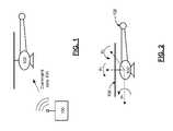
- FIG. 1is a pictorial/block diagram representation of a remote control device 100 and radio controlled aircraft 102 in accordance with an embodiment of the present invention.
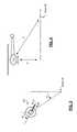
- FIG. 2is a pictorial/graphical representation that illustrates roll, pitch and yaw from the perspective of radio controlled aircraft 102 in accordance with an embodiment of the present invention.
- FIG. 3is a pictorial/graphical representation that illustrates a yaw-axis from the perspective of radio controlled aircraft 102 and an angular orientation with respect to a user coordinate system in accordance with an embodiment of the present invention.
- FIG. 4is a pictorial/graphical representation that illustrates distance and altitude coordinates of radio controlled aircraft 102 with respect to the user coordinate system in accordance with an embodiment of the present invention.
- FIG. 5is a pictorial/graphical representation that further illustrates the perspective of radio controlled aircraft 102 with respect to the remote control device 100 in accordance with an embodiment of the present invention.
- FIG. 6is a schematic block diagram of a remote control device 100 and aircraft 102 in accordance with an embodiment of the present invention.
- FIG. 7is a pictorial representation of a remote control 150 in accordance with an embodiment of the present invention.
- FIG. 8is a pictorial representation of a radio controlled aircraft 102 launching parachutists 166 and 168 in accordance with an embodiment of the present invention.
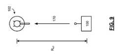
- FIG. 9is a pictorial/block diagram representation of the set-up of remote control device 100 and radio controlled aircraft 102 in accordance with an embodiment of the present invention.
- FIG. 10is a flowchart representation of a method in accordance with an embodiment of the present invention.
- FIG. 11is a flowchart representation of a method in accordance with an embodiment of the present invention.
- FIG. 1is a pictorial/block diagram representation of a remote control device 100 and radio controlled aircraft 102 in accordance with an embodiment of the present invention.
- a radio controlled (RC) aircraft 102such as a helicopter or other aircraft, operates in response to command data 104 received from remote control device 100 .
- remote control 100 and/or RC aircraft 102are configured to provide an easier operation by the user. While described in terms of the operation an RC aircraft, other RC devices such as cars and boats can likewise be implemented in accordance with the present invention.
- FIG. 2is a pictorial/graphical representation that illustrates roll, pitch and yaw axes from the perspective of radio controlled aircraft 102 in accordance with an embodiment of the present invention.
- a coordinate systemis shown that is aligned from the perspective of the aircraft, and in particular from the perspective of an imaginary pilot of the RC aircraft 102 .
- This aircraft coordinate systemprovides a way to describe the orientation of the RC aircraft 102 in three-dimensional space in terms of the angular displacements, roll, pitch and yaw.
- clockwise rotation about a roll axisaligned longitudinally along the length of the aircraft from the front to the tail, is represented by ⁇ 1 .
- clockwise rotationcorresponds to a positive roll.
- rotation about a pitch axisaligned longitudinally from right to left through the center of the cockpit and perpendicular to the roll axis, is represented by ⁇ 2 .
- forward pitch of the aircraft 102is positive pitch.
- the yaw-axisextends vertically through the shaft of main rotor 106 with counter-clockwise displacement represented by ⁇ 3 .
- the aircraft 102includes one or more controls that allow the aircraft to be rotated by an amount ⁇ 1 about the roll axis, an amount ⁇ 2 about the pitch axis and an amount ⁇ 3 about the yaw axis.
- RC aircraft 102is implemented as a helicopter
- forward and backward tilt of the main rotor 106cause, respectively, positive and negative pitch angles ⁇ 2 .
- right and left tilts of the main rotor 106cause, respectively, positive and negative roll angles ⁇ 1 .
- the net thrust produced by the tail rotortaking into consideration any torque induced by the rotation of main rotor 106 , produces a yaw angle ⁇ 3 .
- command data 104 from the remote control device 100are generated in a different coordinate system, such as a user coordinate system that corresponds to the orientation of the user.
- This command data 104can be transformed into control data in the coordinate system of the aircraft so that the RC aircraft 102 can be controlled based on its orientation to the user, rather than the orientation of an imaginary pilot.
- the generation of command data 104 and the transformation into control data used to control the orientation of the RC aircraft 102will be discussed further in conjunction with FIGS. 5 and 6 .
- FIG. 3is a pictorial/graphical representation that illustrates a yaw-axis from the perspective of radio controlled aircraft 102 and an angular orientation with respect to a user coordinate system in accordance with an embodiment of the present invention.
- FIG. 4is a pictorial/graphical representation that illustrates distance and altitude coordinates of radio controlled aircraft 102 with respect to the user coordinate system in accordance with an embodiment of the present invention.
- rotation about a yaw-axisis shown in FIG. 3 in the aircraft coordinate system.
- the yaw-axisextends vertically through the shaft of main rotor 106 with a counter-clockwise angular displacement represented by ⁇ 3 .
- a net counter-clockwise thrust 107 generated by the tail rotor 108causes a positive deviation in the yaw ⁇ 3 .
- a net clockwise thrust 109 generated by the tail rotor 108causes a negative deviation in the yaw ⁇ 3 .
- the origin 90indicates the placement of the origin of a user coordinate system that corresponds to the perspective of the user.
- the user coordinate systemis a polar coordinate system.
- the position of RC aircraft 102 relative to the origin 90can be represented by the altitude Z of the aircraft in relation to the origin 90 , the distance R from the aircraft to the origin 90 , and the angular displacement ⁇ of the aircraft.
- the position of the RC aircraft 102 in three dimensional spacecan be represented in terms of (R, ⁇ , Z) and the orientation of the aircraft can be represented in terms of ( ⁇ 1 , ⁇ 2 , ⁇ 3 ).
- FIG. 5is a pictorial/graphical representation that further illustrates the perspective of radio controlled aircraft 102 with respect to the remote control device 100 in accordance with an embodiment of the present invention.
- this configurationassumes that the user of the remote control device would orient the device with changes of ⁇ , in order to face the RC aircraft 102 , regardless of its position.
- pitch-axis commands from the perspective of the remote control device 100represented by ⁇ 2
- roll-axis commands from the perspective of the remote control device 100represented by ⁇ 1
- ⁇ 3the implementation of a pitch-axis command ⁇ 2 , generally requires both roll-axis and pitch axis controls ⁇ 1 , ⁇ 2 .
- the implementation of a roll-axis command ⁇ 1generally requires also both roll-axis and pitch axis controls ⁇ 1 , ⁇ 2 .
- remote control device 100generates command data 104 that includes orientation commands ⁇ 1 , ⁇ 2 .
- RC aircraft 102is capable of determining position parameters such as ⁇ and ⁇ 3 based on motion data generated by on-board motion sensors.
- RC aircraft 102responds to a lift control L that controls the lift generated by varying either the velocity or pitch of the main rotor 106 and a yaw-axis control V that generates a positive or negative net thrust from the tail rotor 108 .
- Remote control 100can optionally generate additional controls for controlling other control functions as well as other features of the RC aircraft 102 .
- FIG. 6is a schematic block diagram of a remote control device 100 and aircraft 102 in accordance with an embodiment of the present invention.
- remote control device 100includes a user interface 110 such as one or more joy-sticks, click-wheels, buttons, dials, switches, levers or other user interface devices that respond to actions of the user and generate command data 104 in response thereto.
- Radio transmitter 112generates and transmits an RF signal 114 that contains the command data 104 .
- RC aircraft 102includes receiver 120 that is coupled to receive RF signal 114 from the remote control device 100 and to regenerate the command data 104 contained therein.
- command data 104can include data that represents commands such as orientation commands ⁇ 1 , ⁇ 2 in accordance with a coordinate system from a perspective of the remote control device 100 , other command data that may or not be not transformed such as V and L, and other command data corresponding to other function and features.
- RC aircraft 102further includes a motion sensing module 122 that generates motion data 124 based on the motion of the RC aircraft 102 .
- motion sensing module 122includes one or more axes of accelerometers or gyroscopes or other devices that alone, or with further processing by processing module 126 , can generate data that represents ⁇ , ⁇ 3 , and/or other motion parameters such as R, Z, etc., that can be used in transforming the command data 104 to control data 128 .
- Processing module 126transforms the command data 104 into control data 128 in accordance with a coordinate system from a perspective of the RC aircraft. For example, processing module 126 can generate ⁇ 1 , ⁇ 2 , v and l, based on the command data 104 such as ⁇ 1 , ⁇ 2 , V and L, and motion data 124 such as ⁇ , ⁇ 3 .
- This control data 128is provided to a plurality of control devices 130 such as actuators, control surfaces, gimbals or other controllers that control the motion of RC aircraft 102 as previously described.
- control devices 130 and/or processing modulecan further include a feedback controller, state controller or other control mechanism that controls aircraft to the particular values of ⁇ 1 , ⁇ 2 , v and l.
- Processing module 126may be implemented using a shared processing device, individual processing devices, or a plurality of processing devices and may further include memory.
- a processing devicemay be a microprocessor, micro-controller, digital signal processor, microcomputer, central processing unit, field programmable gate array, programmable logic device, state machine, logic circuitry, analog circuitry, digital circuitry, and/or any device that manipulates signals (analog and/or digital) based on operational instructions.
- the memorymay be a single memory device or a plurality of memory devices.
- Such a memory devicemay be a read-only memory, random access memory, volatile memory, non-volatile memory, static memory, dynamic memory, flash memory, and/or any device that stores digital information.
- the processing module 126implements one or more of its functions via a state machine, analog circuitry, digital circuitry, and/or logic circuitry
- the memory storing the corresponding operational instructionsis embedded with the circuitry comprising the state machine, analog circuitry, digital circuitry, and/or logic circuitry.
- processing device 126includes a look-up table, or other routine or application or that generates the control data 128 based on command data 104 and motion data 124 in accordance with the equations presented in conjunction with FIG. 5 or via one or more other transformations.
- the command data 104includes a mode selection that, based on its value, selects whether or not the RC aircraft 102 transforms the command data when calculating the control data 128 .
- the command datacan include a binary indicator that has one value that represents a traditional mode of operation and another value that transforms command data 104 to generate control data 128 .
- the usercan select to operate the RC aircraft 102 in one mode that transforms orientation commands from the remote control device 100 from the perspective of the remote control device 100 to the perspective of the RC aircraft 102 .
- the usercan instead select to operate the RC aircraft 102 in a traditional fashion by generating command data 104 from the perspective of the aircraft itself with yaw-axis controls being proportional to yaw-axis commands and pitch-axis controls being proportional to pitch-axis commands. In this fashion, a user can select the mode he or she finds easiest to use. In addition, different users could select to operate the RC aircraft 102 in different modes.
- RC aircraft 102optionally includes a launch module 132 that responds to launch data 134 included in command data 104 to launch an object from the RC aircraft 102 , such as a parachutist action figure, bomb missile or other toy or object.
- Launch module 132can include a magnetic coupling, retractable hook or other releasable coupling that holds and selectively releases one or more object in respond to the launch command, either successively, one object at a time in response to repeated transmissions of the launch data from the remote control device 100 or based on individual launch data separately identified for each such object.
- user interface 110includes a plurality of spring-loaded interface devices, where each of the plurality of spring-loaded interface devices has a return position that is returned to when no force is applied.
- the remote control device 100commands the RC aircraft to hover or substantially hover when no force is applied to each of the plurality of spring-loaded interface devices.
- the pitch-axis, roll-axis and lift command interface devicescan have a position, such as a center position they return to.
- the center position of the pitch-axis and roll-axis interface devicesoperate to generate command data 104 for the pitch-axis and roll-axis to correspond to horizontal flight or substantially horizontal flight within an acceptable level of tolerance.
- the center position of the lift command interface deviceoperates to generate a lift command that corresponds to a lift force that equals or substantially equals the weight of the RC aircraft 102 .
- the processing module 126can determine a current weight for the RC aircraft 102 based on whether objects have been dropped, how many objects and/or which objects have been dropped, etc.
- FIG. 7is a pictorial representation of a remote control 150 in accordance with an embodiment of the present invention.
- remote control 150such as remote control device 100
- Button 142when pressed by a user, generates a clockwise yaw-velocity command.
- button 144when pressed by a user, generates a counter-clockwise yaw-velocity command.
- Lift command deviceincludes a spring-loaded lever that generates a lift command corresponding to a hover-state, when in the center position.
- the lift commandcan command an increased lift force when pushed up to raise the RC aircraft 102 and a decreased lift force when pushed down to lower the RC aircraft 102 .
- Two-axis joystick 148can be displaced in two-dimensions about a center position. Upward and downward displacements of the joystick 148 correspond to pitch axis commands and right and left displacements correspond to roll-axis commands. When the force is removed from the joystick 148 , it returns to a center position that generates command data 104 corresponding to horizontal flight.
- Remote control 150further includes a reference button, for setting the reference position of the RC aircraft 102 to aid in the determination of motion data 124 , as will be described in greater detail in conjunction with FIG. 8 .
- An on-off button 154is included.
- Mode control button 158is used to select a mode of operation for the remote control. For instance, mode control button 158 can operate on a toggle basis to set or reset the mode to either a mode where joystick 148 and lever 146 operate to generate traditional command data 104 used to generate controls from the perspective of the RC aircraft, or another mode where command data 104 is transformed from the perspective of the remote control 150 to the perspective of the RC aircraft 102 .
- Indicator light 159can be included to indicate the particular mode selected, by a unique color or by being either on or off.
- buttons 156are included for activating other functions and features of RC aircraft 102 such as the generation of launch data 130 for one or more objects or to implement other optional features.
- FIG. 8is a pictorial representation of a radio controlled aircraft 102 launching parachutists 166 and 168 in accordance with an embodiment of the present invention.
- RC aircraft 102includes a launch module 132 that responds to launch data 134 from a remote control device 102 to launch a first action- figure 166 , configured as a parachutist, at a first time along trajectory 164 .
- RC aircraft 102launches a second action- figure 168 , also configured as a parachutist, at a subsequent time along trajectory 162 .
- FIG. 9is a pictorial/block diagram representation of the set-up of remote control device 100 and radio controlled aircraft 102 in accordance with an embodiment of the present invention.
- motion sensing module 124generates motion data 126 based on the relative motion of the RC aircraft 102 .
- the remote control device 100 and RC aircraft 102establish an initial position of RC aircraft 102 that can be used by motion sensing module 124 that serves as an origin or other reference position. For instance, the user can be instructed to place the RC aircraft 102 on the ground, a predetermined distance, R ref , from the remote control device 100 with the tail of the RC aircraft aligned in the direction of remote control device 100 along axis 170 .
- the relative motion of the RC aircraftreflected by motion data 124 , can be used to determine a position and orientation of the RC aircraft 102 from the origin established by the position of remote control 100 during setup.
- FIG. 10is a flowchart representation of a method in accordance with an embodiment of the present invention. In particular a method is presented for use with one or more features or functions presented in conjunction with FIGS. 1-9 .
- an RF signalis received from a remote control device, the RF signal containing command data in accordance with a first coordinate system, wherein the first coordinate system is from a perspective of the remote control device.
- motion datais generated based on the motion of the RC aircraft.
- the command datais transformed into control data in accordance with a second coordinate system, wherein the second coordinate system is from a perspective of the RC aircraft.
- the motion of the RC aircraftis controlled based on the control data.
- the command dataincludes roll-axis command data and pitch-axis command data
- the control dataincludes roll-axis control data
- the motion dataincludes yaw-axis motion data
- step 404includes generating the roll-axis control data as a function of the roll-axis command data, pitch-axis command data and the yaw-axis motion data.
- the command datacan include roll-axis command data and pitch-axis command data
- the control datacan include pitch-axis control data
- the motion dataincludes yaw-axis motion data
- step 404includes generating the pitch-axis control data as a function of the roll-axis command data, pitch-axis command data and the yaw-axis motion data.
- the RF signalcan include mode data, and wherein, when the mode data has a first value, step 404 is selectively bypassed and the control data generated in proportional to the command data.
- the command datacan include lift command data and the control data can include lift control data, wherein step 404 includes generating the lift control data based on a weight of the RC aircraft.
- the command datacan include yaw-velocity command data and the control data can includes yaw-velocity control data and wherein step 404 includes generating yaw-velocity control data as a proportion of the yaw-velocity command data.
- FIG. 11is a flowchart representation of a method in accordance with an embodiment of the present invention.
- a methodis presented for use with one or more features or functions presented in conjunction with FIGS. 1-10 wherein command data includes launch data.
- command dataincludes launch data.
- an objectis launched from the RC aircraft in response to the launch data.
- the objectincludes a parachute, parachutist action figure, toy missile or bomb or other object.
- the terms “substantially” and “approximately”provides an industry-accepted tolerance for its corresponding term and/or relativity between items. Such an industry-accepted tolerance ranges from less than one percent to fifty percent. Such relativity between items ranges from a difference of a few percent to order of magnitude differences.
- the term(s) “coupled to” and/or “coupling” and/orincludes direct coupling between items and/or indirect coupling between items via an intervening item (e.g., an item includes, but is not limited to, a component, an element, a circuit, and/or a module) where, for indirect coupling, the intervening item does not modify the information of a signal but may adjust its current level, voltage level, and/or power level.
- an intervening iteme.g., an item includes, but is not limited to, a component, an element, a circuit, and/or a module
- inferred couplingi.e., where one element is coupled to another element by inference
- the term “operable to”indicates that an item includes one or more of power connections, input(s), output(s), etc., to perform one or more its corresponding functions and may further include inferred coupling to one or more other items.
- the term “associated with”,includes direct and/or indirect coupling of separate items and/or one item being embedded within another item.
Landscapes
- Engineering & Computer Science (AREA)
- Aviation & Aerospace Engineering (AREA)
- Remote Sensing (AREA)
- Radar, Positioning & Navigation (AREA)
- Physics & Mathematics (AREA)
- General Physics & Mathematics (AREA)
- Automation & Control Theory (AREA)
- Mechanical Engineering (AREA)
- Computer Networks & Wireless Communication (AREA)
- Toys (AREA)
Abstract
Description
φ1=ψ1cos(φ3−θ)+ψ2sin(φ3−θ) (1)
φ2=ψ2cos(φ3−θ)−ψ1sin(φ3−θ) (2)
In this fashion, when a user commands the
- if the RC aircraft is facing toward the
remote control device 100, a command to pitch forward could be implemented with a pitch backward control; - if the RC aircraft is facing perpendicular to the
remote control device 100, a command to pitch forward could be implemented with either a roll-right control or a roll-left control, depending on whether θ−φ3=90° or θ−φ3=−90°;
In other circumstances, some other combination of both roll-axis and pitch-axis controls φ1, φ2is required, as set forth in the equations (1) and (2) above. Using these transformations, aremote control device 100 can command theRC aircraft 102 from the perspective of a user, independent of a yaw-orientation of the RC aircraft. For instance, when a user commands theRC aircraft 102 to pitch-forward or roll-left (from the user's perspective), the RC aircraft pitches forward or rolls left, regardless of the value of θ or φ3.
- if the RC aircraft is facing toward the
Claims (10)
Priority Applications (10)
| Application Number | Priority Date | Filing Date | Title |
|---|---|---|---|
| US12/029,470US8200375B2 (en) | 2008-02-12 | 2008-02-12 | Radio controlled aircraft, remote controller and methods for use therewith |
| US13/471,642US8380368B2 (en) | 2008-02-12 | 2012-05-15 | Radio controlled aircraft, remote controller and methods for use therewith |
| US13/688,886US8649918B2 (en) | 2008-02-12 | 2012-11-29 | Radio controlled vehicle, remote controller and methods for use therewith |
| US14/102,995US9079116B2 (en) | 2008-02-12 | 2013-12-11 | Radio controlled aircraft, remote controller and methods for use therewith |
| US14/724,037US9568913B2 (en) | 2008-02-12 | 2015-05-28 | Radio controlled aircraft, remote controller and methods for use therewith |
| US15/392,687US10248117B2 (en) | 2008-02-12 | 2016-12-28 | Radio controlled aircraft, remote controller and methods for use therewith |
| US15/923,289US10095226B1 (en) | 2008-02-12 | 2018-03-16 | Radio controlled aircraft, remote controller and methods for use therewith |
| US16/229,994US11281205B2 (en) | 2008-02-12 | 2018-12-21 | Radio controlled aircraft, remote controller and methods for use therewith |
| US17/666,698US12130619B2 (en) | 2008-02-12 | 2022-02-08 | Radio controlled aircraft, remote controller and methods for use therewith |
| US18/928,430US20250123619A1 (en) | 2008-02-12 | 2024-10-28 | Radio controlled aircraft, remote controller and methods for use therewith |
Applications Claiming Priority (1)
| Application Number | Priority Date | Filing Date | Title |
|---|---|---|---|
| US12/029,470US8200375B2 (en) | 2008-02-12 | 2008-02-12 | Radio controlled aircraft, remote controller and methods for use therewith |
Related Child Applications (1)
| Application Number | Title | Priority Date | Filing Date |
|---|---|---|---|
| US13/471,642DivisionUS8380368B2 (en) | 2008-02-12 | 2012-05-15 | Radio controlled aircraft, remote controller and methods for use therewith |
Publications (2)
| Publication Number | Publication Date |
|---|---|
| US20090204276A1 US20090204276A1 (en) | 2009-08-13 |
| US8200375B2true US8200375B2 (en) | 2012-06-12 |
Family
ID=40939593
Family Applications (10)
| Application Number | Title | Priority Date | Filing Date |
|---|---|---|---|
| US12/029,470Expired - Fee RelatedUS8200375B2 (en) | 2008-02-12 | 2008-02-12 | Radio controlled aircraft, remote controller and methods for use therewith |
| US13/471,642Expired - Fee RelatedUS8380368B2 (en) | 2008-02-12 | 2012-05-15 | Radio controlled aircraft, remote controller and methods for use therewith |
| US13/688,886ActiveUS8649918B2 (en) | 2008-02-12 | 2012-11-29 | Radio controlled vehicle, remote controller and methods for use therewith |
| US14/102,995Expired - Fee RelatedUS9079116B2 (en) | 2008-02-12 | 2013-12-11 | Radio controlled aircraft, remote controller and methods for use therewith |
| US14/724,037Expired - Fee RelatedUS9568913B2 (en) | 2008-02-12 | 2015-05-28 | Radio controlled aircraft, remote controller and methods for use therewith |
| US15/392,687ActiveUS10248117B2 (en) | 2008-02-12 | 2016-12-28 | Radio controlled aircraft, remote controller and methods for use therewith |
| US15/923,289ActiveUS10095226B1 (en) | 2008-02-12 | 2018-03-16 | Radio controlled aircraft, remote controller and methods for use therewith |
| US16/229,994Active2029-10-31US11281205B2 (en) | 2008-02-12 | 2018-12-21 | Radio controlled aircraft, remote controller and methods for use therewith |
| US17/666,698Active2029-02-27US12130619B2 (en) | 2008-02-12 | 2022-02-08 | Radio controlled aircraft, remote controller and methods for use therewith |
| US18/928,430PendingUS20250123619A1 (en) | 2008-02-12 | 2024-10-28 | Radio controlled aircraft, remote controller and methods for use therewith |
Family Applications After (9)
| Application Number | Title | Priority Date | Filing Date |
|---|---|---|---|
| US13/471,642Expired - Fee RelatedUS8380368B2 (en) | 2008-02-12 | 2012-05-15 | Radio controlled aircraft, remote controller and methods for use therewith |
| US13/688,886ActiveUS8649918B2 (en) | 2008-02-12 | 2012-11-29 | Radio controlled vehicle, remote controller and methods for use therewith |
| US14/102,995Expired - Fee RelatedUS9079116B2 (en) | 2008-02-12 | 2013-12-11 | Radio controlled aircraft, remote controller and methods for use therewith |
| US14/724,037Expired - Fee RelatedUS9568913B2 (en) | 2008-02-12 | 2015-05-28 | Radio controlled aircraft, remote controller and methods for use therewith |
| US15/392,687ActiveUS10248117B2 (en) | 2008-02-12 | 2016-12-28 | Radio controlled aircraft, remote controller and methods for use therewith |
| US15/923,289ActiveUS10095226B1 (en) | 2008-02-12 | 2018-03-16 | Radio controlled aircraft, remote controller and methods for use therewith |
| US16/229,994Active2029-10-31US11281205B2 (en) | 2008-02-12 | 2018-12-21 | Radio controlled aircraft, remote controller and methods for use therewith |
| US17/666,698Active2029-02-27US12130619B2 (en) | 2008-02-12 | 2022-02-08 | Radio controlled aircraft, remote controller and methods for use therewith |
| US18/928,430PendingUS20250123619A1 (en) | 2008-02-12 | 2024-10-28 | Radio controlled aircraft, remote controller and methods for use therewith |
Country Status (1)
| Country | Link |
|---|---|
| US (10) | US8200375B2 (en) |
Cited By (15)
| Publication number | Priority date | Publication date | Assignee | Title |
|---|---|---|---|---|
| US20130248648A1 (en)* | 2012-03-21 | 2013-09-26 | Sikorsky Aircraft Corporation | Portable Control System For Rotary-Wing Aircraft Load Management |
| US8577520B1 (en) | 2012-09-26 | 2013-11-05 | Silverlit Limited | Altitude control of an indoor flying toy |
| US8639400B1 (en)* | 2012-09-26 | 2014-01-28 | Silverlit Limited | Altitude control of an indoor flying toy |
| WO2014109657A1 (en) | 2013-01-09 | 2014-07-17 | Far Away Sensing | System and process of remote command of vehicles by copy of spatial orientation comprising a warning subsystem for non executable orders |
| US9004973B2 (en) | 2012-10-05 | 2015-04-14 | Qfo Labs, Inc. | Remote-control flying copter and method |
| WO2015066084A1 (en) | 2013-10-28 | 2015-05-07 | Traxxas Lp | Ground vehicle-link control for remote control aircraft |
| USD767510S1 (en)* | 2015-04-20 | 2016-09-27 | SZ DJI Technology Co., Ltd. | Remote controller |
| DE102017111780A1 (en) | 2016-06-06 | 2017-12-07 | Traxxas Lp | Ground vehicle-like control for a remote-controlled aircraft |
| US9855512B1 (en)* | 2016-08-26 | 2018-01-02 | Dongguan Silverlit Toys, Co., Ltd. | Horizontal control of an indoor flying toy |
| US20180074487A1 (en)* | 2015-05-18 | 2018-03-15 | SZ DJI Technology Co., Ltd. | Control methods and apparatuses based on headless mode for unmanned aerial vehicle |
| US10095226B1 (en) | 2008-02-12 | 2018-10-09 | Drone-Control, Llc | Radio controlled aircraft, remote controller and methods for use therewith |
| US10258888B2 (en) | 2015-11-23 | 2019-04-16 | Qfo Labs, Inc. | Method and system for integrated real and virtual game play for multiple remotely-controlled aircraft |
| WO2019190821A1 (en)* | 2018-03-29 | 2019-10-03 | Walmart Apollo, Llc | Movable safety guard system for unmanned aerial vehicle propellers |
| US11385645B2 (en)* | 2013-07-31 | 2022-07-12 | SZ DJI Technology Co., Ltd. | Remote control method and terminal |
| US11962905B2 (en) | 2013-10-08 | 2024-04-16 | Sz Dji Osmo Technology Co., Ltd. | Apparatus and methods for stabilization and vibration reduction |
Families Citing this family (29)
| Publication number | Priority date | Publication date | Assignee | Title |
|---|---|---|---|---|
| US8089225B2 (en)* | 2008-10-29 | 2012-01-03 | Honeywell International Inc. | Systems and methods for inertially controlling a hovering unmanned aerial vehicles |
| TW201235949A (en)* | 2011-02-24 | 2012-09-01 | Hon Hai Prec Ind Co Ltd | Unmanned aerial vehicle and method for adjusting control command of the unmanned aerial vehicle |
| FR2985329B1 (en)* | 2012-01-04 | 2015-01-30 | Parrot | METHOD FOR INTUITIVE CONTROL OF A DRONE USING A REMOTE CONTROL APPARATUS |
| US20140049642A1 (en)* | 2012-08-14 | 2014-02-20 | Yunshao Jiang | Gas monitoring system and gas monitor |
| US9650155B2 (en) | 2013-06-25 | 2017-05-16 | SZ DJI Technology Co., Ltd | Aircraft control apparatus, control system and control method |
| CN105912014B (en)* | 2013-06-25 | 2019-01-15 | 深圳市大疆创新科技有限公司 | Flight control and control method |
| CN103559338B (en)* | 2013-10-21 | 2016-06-15 | 南京航空航天大学 | A kind of parachute operating characteristic emulation mode |
| FR3015574B1 (en)* | 2013-12-20 | 2019-05-03 | Safran Helicopter Engines | METHOD FOR AUTOMATICALLY CONTROLLING THE OPERATING REGIME OF A TURBOMOTOR OF A HELICOPTER, CORRESPONDING CONTROL DEVICE AND HELICOPTER EQUIPPED WITH SUCH A DEVICE |
| CN107409051B (en) | 2015-03-31 | 2021-02-26 | 深圳市大疆创新科技有限公司 | Authentication system and method for generating flight controls |
| WO2016154945A1 (en)* | 2015-03-31 | 2016-10-06 | SZ DJI Technology Co., Ltd. | Authentication systems and methods for detecting unauthorized uav activity |
| JP6459014B2 (en) | 2015-03-31 | 2019-01-30 | エスゼット ディージェイアイ テクノロジー カンパニー リミテッドSz Dji Technology Co.,Ltd | Geo-fencing device |
| CN104898699B (en)* | 2015-05-28 | 2020-03-17 | 小米科技有限责任公司 | Flight control method and device and electronic equipment |
| US10094669B2 (en)* | 2015-10-29 | 2018-10-09 | Horizon Hobby, LLC | Systems and methods for inertially-instituted binding of a RC vehicle |
| US11327477B2 (en) | 2015-12-31 | 2022-05-10 | Powervision Robot Inc. | Somatosensory remote controller, somatosensory remote control flight system and method, and head-less control method |
| JP6933656B2 (en)* | 2016-02-29 | 2021-09-08 | エスゼット ディージェイアイ テクノロジー カンパニー リミテッドSz Dji Technology Co.,Ltd | Methods, systems and computer readable media for motion control of flight devices |
| CN105999729A (en)* | 2016-05-06 | 2016-10-12 | 腾讯科技(深圳)有限公司 | An apparatus control system, method and device |
| EP3443421A4 (en)* | 2016-06-23 | 2019-03-13 | SZ DJI Technology Co., Ltd. | SYSTEMS AND METHODS FOR CONTROLLING MOBILE OBJECT BEHAVIOR |
| CN106023560A (en)* | 2016-07-13 | 2016-10-12 | 无锡觅睿恪科技有限公司 | Folding type unmanned aerial vehicle remote controller |
| CN106155077A (en)* | 2016-09-06 | 2016-11-23 | 哈尔滨理工大学 | A kind of four-rotor aircraft control system and control method |
| CN106444848B (en)* | 2016-11-28 | 2018-11-30 | 广州极飞科技有限公司 | Control the method and device of unmanned plane during flying |
| JP7087475B2 (en)* | 2018-03-09 | 2022-06-21 | 株式会社タダノ | Mobile crane with remote control terminal and remote control terminal |
| CN111052020B (en) | 2018-04-02 | 2024-09-13 | 深圳市大疆创新科技有限公司 | Navigation equipment |
| CN209612208U (en)* | 2018-11-30 | 2019-11-12 | 深圳市大疆创新科技有限公司 | Remote controler |
| US20210339154A1 (en)* | 2019-06-08 | 2021-11-04 | Herman Eugene Mitchell | Racer |
| CN111045440B (en)* | 2019-12-16 | 2020-12-15 | 北京航空航天大学 | A fast roll control method for a hypersonic vehicle in the dive segment |
| CN111813135B (en)* | 2020-06-29 | 2023-03-31 | 西南电子技术研究所(中国电子科技集团公司第十研究所) | Dual-coordinate system full-airspace array beam tracking method |
| USD989193S1 (en) | 2020-07-18 | 2023-06-13 | Herman Eugene Mitchell | Action figure racer |
| WO2024002479A1 (en)* | 2022-06-29 | 2024-01-04 | Anybotics Ag | Method to control a movement of a robot and a controller |
| US12145753B2 (en)* | 2022-08-09 | 2024-11-19 | Pete Bitar | Compact and lightweight drone delivery device called an ArcSpear electric jet drone system having an electric ducted air propulsion system and being relatively difficult to track in flight |
Citations (8)
| Publication number | Priority date | Publication date | Assignee | Title |
|---|---|---|---|---|
| US5859372A (en)* | 1994-04-11 | 1999-01-12 | Neltoft; Peter | Device for use in manual control of the movement of a real or imaginary object |
| US20020163905A1 (en)* | 2001-03-29 | 2002-11-07 | Tord Brabrand | Remote control system |
| US6694228B2 (en)* | 2002-05-09 | 2004-02-17 | Sikorsky Aircraft Corporation | Control system for remotely operated vehicles for operational payload employment |
| US20040068333A1 (en)* | 2002-10-04 | 2004-04-08 | Comau S.P.A. | Portable terminal for controlling, programming and/or teaching robots or similar automatic apparatuses |
| US20060144994A1 (en)* | 2002-08-30 | 2006-07-06 | Peter Spirov | Homeostatic flying hovercraft |
| US20100161155A1 (en)* | 2007-01-02 | 2010-06-24 | Janick Simeray | Automatic flight control helicopter |
| US7873444B1 (en)* | 2007-02-08 | 2011-01-18 | Lockheed Martin Corporation | Controlling movement of an unmanned vehicle |
| US8014909B2 (en)* | 2004-03-25 | 2011-09-06 | Bell Helicopter Textron Inc. | Control system for vehicles |
Family Cites Families (110)
| Publication number | Priority date | Publication date | Assignee | Title |
|---|---|---|---|---|
| US418805A (en) | 1890-01-07 | Island | ||
| US3094299A (en) | 1958-08-28 | 1963-06-18 | North American Aviation Inc | Autopilot |
| US3053480A (en) | 1959-10-06 | 1962-09-11 | Piasecki Aircraft Corp | Omni-directional, vertical-lift, helicopter drone |
| US3534399A (en) | 1968-07-22 | 1970-10-13 | Rca Corp | Area navigation method and apparatus for aircraft with vhf-omnirange (vor) and distance measuring equipment (dme) |
| JPS519854B2 (en) | 1973-05-10 | 1976-03-31 | ||
| US4375631A (en) | 1981-04-09 | 1983-03-01 | Ampex Corporation | Joystick control |
| US4466774A (en) | 1982-08-30 | 1984-08-21 | United Technologies Corporation | Composite flexbeam joint |
| US4490710A (en) | 1982-11-05 | 1984-12-25 | Kraft Systems, Inc. | Control stick assembly |
| JPS60234683A (en) | 1984-05-04 | 1985-11-21 | 井筒屋 皖庸 | Posture controller in radio control helicopter |
| US4770607A (en) | 1987-04-27 | 1988-09-13 | United Technologies Corporation | Rotor blade construction for circulation control aircraft |
| IL85731A (en) | 1988-03-14 | 1995-05-26 | B T A Automatic Piloting Syste | Apparatus and method for controlling aircraft, particularly remotely-controlled aircraft |
| US5001646A (en) | 1988-12-19 | 1991-03-19 | Mcdonnell Douglas Corporation | Automated helicopter flight control system |
| US5048652A (en) | 1989-11-24 | 1991-09-17 | United Technologies Corporation | Progressive engagement clutch |
| US5058824A (en) | 1989-12-21 | 1991-10-22 | United Technologies Corporation | Servo control system for a co-axial rotary winged aircraft |
| US5043646A (en) | 1990-05-01 | 1991-08-27 | Smith Engineering | Remote control direction selecting system |
| US5152478A (en) | 1990-05-18 | 1992-10-06 | United Technologies Corporation | Unmanned flight vehicle including counter rotating rotors positioned within a toroidal shroud and operable to provide all required vehicle flight controls |
| JP3022979B2 (en) | 1990-06-12 | 2000-03-21 | ヤマハ発動機株式会社 | Unmanned helicopter control system |
| JPH0519854A (en) | 1991-07-12 | 1993-01-29 | Pioneer Electron Corp | Controller and monitor device for movement of moving body |
| JPH0642270Y2 (en) | 1991-08-09 | 1994-11-02 | 双葉電子工業株式会社 | Stick lever device |
| JP3162164B2 (en) | 1992-04-09 | 2001-04-25 | ヤマハ発動機株式会社 | Remote control helicopter controller |
| US5364230A (en) | 1992-06-22 | 1994-11-15 | United Technologies Corporation | Rotor blade subassembly for a rotor assembly having ducted, coaxial counter-rotating rotors |
| US5340279A (en) | 1992-06-22 | 1994-08-23 | United Technologies Corporation | Snubber assembly for a rotor assembly having ducted, coaxial counter-rotating rotors |
| DE69332506T2 (en) | 1992-06-22 | 2003-07-10 | United Technologies Corp., Stratford | Coaxial translation / centering hub sub-assembly for rotor assembly |
| US5281099A (en) | 1992-06-22 | 1994-01-25 | United Technologies Corporation | Integrated spline/cone seat subassembly for a rotor assembly having ducted, coaxial counter-rotating rotors |
| US5226350A (en) | 1992-06-22 | 1993-07-13 | United Technologies Corporation | Drive train assembly for a rotor assembly having ducted, coaxial counter-rotating rotors |
| US5351913A (en) | 1992-06-22 | 1994-10-04 | United Technologies Corporation | Coaxial transmission/center hub subassembly for a rotor assembly having ducted, coaxial counter-rotating rotors |
| US5277380A (en) | 1992-06-22 | 1994-01-11 | United Technologies Corporation | Toroidal fuselage structure for unmanned aerial vehicles having ducted, coaxial, counter-rotating rotors |
| JPH0619854A (en) | 1992-06-29 | 1994-01-28 | Canon Inc | Electronic unit |
| JPH07178235A (en) | 1993-12-21 | 1995-07-18 | Casio Comput Co Ltd | Control device |
| US5552983A (en) | 1994-03-02 | 1996-09-03 | United Technologies Corporation | Variable referenced control system for remotely operated vehicles |
| JPH07300096A (en) | 1994-03-10 | 1995-11-14 | Yamaha Motor Co Ltd | Attitude control device for unmanned helicopter |
| JP3185081B2 (en) | 1994-03-10 | 2001-07-09 | ヤマハ発動機株式会社 | Unmanned helicopter attitude control system |
| JP3189027B2 (en) | 1994-03-22 | 2001-07-16 | ヤマハ発動機株式会社 | Aircraft attitude control device |
| US5429089A (en) | 1994-04-12 | 1995-07-04 | United Technologies Corporation | Automatic engine speed hold control system |
| US5575438A (en) | 1994-05-09 | 1996-11-19 | United Technologies Corporation | Unmanned VTOL ground surveillance vehicle |
| JP3297830B2 (en) | 1994-06-29 | 2002-07-02 | ヤンマー農機株式会社 | Helicopter remote control |
| JP3286929B2 (en) | 1995-03-06 | 2002-05-27 | ヤマハ発動機株式会社 | Unmanned helicopter controller |
| JPH08239097A (en) | 1995-03-06 | 1996-09-17 | Yamaha Motor Co Ltd | Unmanned helicopter |
| EP0752634A1 (en) | 1995-07-07 | 1997-01-08 | Sacom Co., Ltd | Apparatus for controlling the attitude of a radio-controlled helicopter |
| US5890441A (en) | 1995-09-07 | 1999-04-06 | Swinson Johnny | Horizontal and vertical take off and landing unmanned aerial vehicle |
| US5676334A (en) | 1995-12-21 | 1997-10-14 | Sikorsky Aircraft Corporation | Cyclic minimizer through alignment of the center of gravity and direction of flight vectors |
| JP2000502632A (en) | 1995-12-21 | 2000-03-07 | シコルスキー エアクラフト コーポレイション | Method and apparatus for controlling a symmetrical unmanned aerial vehicle |
| JPH1096A (en) | 1996-06-13 | 1998-01-06 | Nikken Chem Co Ltd | Method for producing erythritol using microorganism |
| JP3645038B2 (en) | 1996-07-05 | 2005-05-11 | 富士重工業株式会社 | Aircraft flight control equipment |
| US6460810B2 (en) | 1996-09-06 | 2002-10-08 | Terry Jack James | Semiautonomous flight director |
| JPH1193612A (en) | 1997-09-16 | 1999-04-06 | Toshiba Corp | Wobble motor |
| JPH1193812A (en) | 1997-09-25 | 1999-04-06 | Yamaha Motor Co Ltd | Engine starter of unmanned helicopter |
| US6092007A (en) | 1998-04-29 | 2000-07-18 | Sikorsky Aircraft Corporation | Aircraft course correction for wind and fuzzy logic course intercept profile based upon accuracy and efficiency |
| US6076024A (en) | 1998-04-29 | 2000-06-13 | Sikorsky Aircraft Corporation | Earth-referenced wind adjustment for hovering aircraft |
| JP4109767B2 (en) | 1998-10-09 | 2008-07-02 | ヤマハ発動機株式会社 | Unmanned helicopter flight control system. |
| USD418805S (en) | 1998-11-24 | 2000-01-11 | Sikorsky Aircraft Corporation | Unmanned multi-mode vertical take off and landing aircraft |
| US6270038B1 (en) | 1999-04-22 | 2001-08-07 | Sikorsky Aircraft Corporation | Unmanned aerial vehicle with counter-rotating ducted rotors and shrouded pusher-prop |
| US6170778B1 (en) | 1999-04-22 | 2001-01-09 | Sikorsky Aircraft Corporation | Method of reducing a nose-up pitching moment on a ducted unmanned aerial vehicle |
| JP2001209427A (en) | 2000-01-28 | 2001-08-03 | Fuji Heavy Ind Ltd | Unmanned airplane remote control |
| JP2001246177A (en) | 2000-03-06 | 2001-09-11 | Japan Aviation Electronics Industry Ltd | Remote control device with safety function |
| JP2001306143A (en) | 2000-04-21 | 2001-11-02 | Yamaha Motor Co Ltd | Flight control system for unmanned helicopter |
| JP2001306144A (en) | 2000-04-21 | 2001-11-02 | Yamaha Motor Co Ltd | Unmanned helicopter flight control system. |
| JP2001301695A (en) | 2000-04-21 | 2001-10-31 | Yamaha Motor Co Ltd | Flight control system for unmanned helicopter |
| DE60113552T3 (en)* | 2000-05-17 | 2009-07-30 | The Boeing Co., Chicago | INTUITIVE VEHICLE AND MACHINE CONTROL |
| FR2809026B1 (en) | 2000-05-18 | 2003-05-16 | Philippe Louvel | ELECTRIC FLYING SAUCER, PILOTED AND REMOTELY POWERED |
| JP4675023B2 (en) | 2000-06-05 | 2011-04-20 | ▲吉▼川 英之 | Remote control traveling device |
| US20050127242A1 (en)* | 2000-08-08 | 2005-06-16 | Rivers Eugene P.Jr. | Payload dispensing system particularly suited for unmanned aerial vehicles |
| JP4532752B2 (en) | 2001-01-23 | 2010-08-25 | ▲吉▼川 英之 | Remote control device |
| US7497759B1 (en) | 2001-03-28 | 2009-03-03 | Steven Davis | Directionally controllable, self-stabilizing, rotating flying vehicle |
| US6478262B1 (en) | 2001-07-17 | 2002-11-12 | Sikorsky Aircraft Corporation | Flight control system for a hybrid aircraft in the yaw axis |
| JP3818914B2 (en) | 2001-12-25 | 2006-09-06 | 株式会社東京マルイ | Aircraft toy that can reproduce flight attitude |
| JP2003202922A (en) | 2002-01-08 | 2003-07-18 | Yamaha Corp | Wireless steering system and wireless steering method |
| JP4532820B2 (en) | 2002-02-14 | 2010-08-25 | ▲吉▼川 英之 | Remote control device |
| US6629023B1 (en) | 2002-04-30 | 2003-09-30 | Sikorsky Aircraft Corporation | Method for performing an automated category a approach maneuver |
| US6527225B1 (en) | 2002-04-30 | 2003-03-04 | Sikorsky Aircraft Corporation | Method for performing an automated category a takeoff |
| US6697715B1 (en) | 2002-06-19 | 2004-02-24 | The United States Of America As Represented By The Secretary Of The Navy | Instinctive steering system and method for reducing operator error in controlling a vehicle remotely |
| US6885917B2 (en) | 2002-11-07 | 2005-04-26 | The Boeing Company | Enhanced flight control systems and methods for a jet powered tri-mode aircraft |
| JP4141860B2 (en) | 2003-02-26 | 2008-08-27 | 健蔵 野波 | Autonomous control device and program for small unmanned helicopter |
| JP4116476B2 (en) | 2003-03-07 | 2008-07-09 | ヤマハ発動機株式会社 | Display device for unmanned helicopter and method of using the same |
| JP2004268730A (en) | 2003-03-07 | 2004-09-30 | Yamaha Motor Co Ltd | Attitude control method for unmanned helicopter |
| JP4130598B2 (en) | 2003-03-07 | 2008-08-06 | ヤマハ発動機株式会社 | GPS control method for unmanned helicopter |
| JP4157397B2 (en) | 2003-03-07 | 2008-10-01 | ヤマハ発動機株式会社 | Speed calculation circuit for moving body and moving body |
| JP4084215B2 (en) | 2003-03-07 | 2008-04-30 | ヤマハ発動機株式会社 | Control method of unmanned helicopter |
| JP4084214B2 (en) | 2003-03-07 | 2008-04-30 | ヤマハ発動機株式会社 | Engine rotation control method of unmanned helicopter |
| JP4313066B2 (en) | 2003-03-27 | 2009-08-12 | ヤマハ発動機株式会社 | Unmanned helicopter management system |
| US7059931B2 (en) | 2003-05-27 | 2006-06-13 | Veratech Aero-Rpv Corporation | Reduced visibility rotorcraft and method of controlling flight of reduced visibility rotorcraft |
| JP2005028935A (en) | 2003-07-09 | 2005-02-03 | Fuji Heavy Ind Ltd | Ultra-compact unmanned aerial vehicle |
| US7532988B2 (en) | 2003-08-07 | 2009-05-12 | Sikorsky Aircraft Corporation | Virtual load monitoring system and method |
| US7286913B2 (en) | 2003-10-23 | 2007-10-23 | International Business Machines Corporation | Navigating a UAV with telemetry through a socket |
| US7130741B2 (en) | 2003-10-23 | 2006-10-31 | International Business Machines Corporation | Navigating a UAV with a remote control device |
| US6856894B1 (en) | 2003-10-23 | 2005-02-15 | International Business Machines Corporation | Navigating a UAV under remote control and manual control with three dimensional flight depiction |
| KR100590549B1 (en) | 2004-03-12 | 2006-06-19 | 삼성전자주식회사 | Remote Control Method of Robot Using 3D Pointing Method and Robot Control System Implementing It |
| CA2773702C (en) | 2004-03-25 | 2014-07-22 | Bell Helicopter Textron Inc. | Control system for vehicles |
| BRPI0418962A (en) | 2004-07-29 | 2007-12-04 | Bell Helicopter Textron Inc | method and apparatus for tilting rotor aircraft flight control |
| GB2418405B (en) | 2004-09-23 | 2010-03-10 | Paul Vincenzi | Rotorcraft |
| US7407424B2 (en) | 2005-01-10 | 2008-08-05 | Silverlit Toys Manufactory, Ltd. | Spatial navigation system and method for programmable flying objects |
| US8083569B2 (en) | 2005-02-04 | 2011-12-27 | Nicholas Sotereanos | Remotely controlled vehicle |
| JP4532318B2 (en) | 2005-03-25 | 2010-08-25 | ヤマハ発動機株式会社 | Unmanned helicopter |
| JP2006289531A (en) | 2005-04-07 | 2006-10-26 | Seiko Epson Corp | Movement control device for robot position teaching, robot position teaching device, movement control method for robot position teaching, robot position teaching method, and movement control program for robot position teaching |
| JP4644522B2 (en) | 2005-05-06 | 2011-03-02 | 国立大学法人 千葉大学 | Autonomous flight control device and autonomous flight control method for small unmanned helicopter |
| JP2007130146A (en) | 2005-11-09 | 2007-05-31 | Taiyo Kogyo Kk | Radio-controlled flying toy |
| JP2007203008A (en) | 2006-01-31 | 2007-08-16 | Shinzo Tanaka | Vertical taking off and landing airplane |
| US7984146B2 (en) | 2006-05-04 | 2011-07-19 | Sikorsky Aircraft Corporation | Aircraft health and usage monitoring system with comparative fleet statistics |
| CN100391790C (en) | 2006-05-18 | 2008-06-04 | 战强 | Multi-rotor aerocraft |
| IL176200A (en) | 2006-06-08 | 2013-03-24 | Israel Aerospace Ind Ltd | Unmanned air vehicle system |
| CN200976108Y (en) | 2006-11-24 | 2007-11-14 | 中国科学院沈阳自动化研究所 | Small-size unmanned helicopter is flight control system independently |
| US7806371B2 (en)* | 2006-12-07 | 2010-10-05 | Troutman S Clayton | Remote control model aircraft with laser tag shooting action |
| US7871044B2 (en) | 2007-05-23 | 2011-01-18 | Honeywell International Inc. | Method for vertical takeoff from and landing on inclined surfaces |
| IL188655A (en)* | 2008-01-08 | 2011-09-27 | Rafael Advanced Defense Sys | System and method for navigating a remote control vehicle past obstacles |
| US8200375B2 (en)* | 2008-02-12 | 2012-06-12 | Stuckman Katherine C | Radio controlled aircraft, remote controller and methods for use therewith |
| US8401666B2 (en) | 2008-07-11 | 2013-03-19 | Medtronic, Inc. | Modification profiles for posture-responsive therapy |
| US8903568B1 (en)* | 2013-07-31 | 2014-12-02 | SZ DJI Technology Co., Ltd | Remote control method and terminal |
| WO2016049924A1 (en)* | 2014-09-30 | 2016-04-07 | SZ DJI Technology Co., Ltd. | Systems and methods for flight simulation |
| EP3108318B1 (en)* | 2014-09-30 | 2019-07-10 | SZ DJI Technology Co., Ltd. | System and method for data recording and analysis |
| US11427305B1 (en)* | 2021-09-16 | 2022-08-30 | Beta Air, Llc | Methods and systems for flight control for managing actuators for an electric aircraft |
- 2008
- 2008-02-12USUS12/029,470patent/US8200375B2/ennot_activeExpired - Fee Related
- 2012
- 2012-05-15USUS13/471,642patent/US8380368B2/ennot_activeExpired - Fee Related
- 2012-11-29USUS13/688,886patent/US8649918B2/enactiveActive
- 2013
- 2013-12-11USUS14/102,995patent/US9079116B2/ennot_activeExpired - Fee Related
- 2015
- 2015-05-28USUS14/724,037patent/US9568913B2/ennot_activeExpired - Fee Related
- 2016
- 2016-12-28USUS15/392,687patent/US10248117B2/enactiveActive
- 2018
- 2018-03-16USUS15/923,289patent/US10095226B1/enactiveActive
- 2018-12-21USUS16/229,994patent/US11281205B2/enactiveActive
- 2022
- 2022-02-08USUS17/666,698patent/US12130619B2/enactiveActive
- 2024
- 2024-10-28USUS18/928,430patent/US20250123619A1/enactivePending
Patent Citations (8)
| Publication number | Priority date | Publication date | Assignee | Title |
|---|---|---|---|---|
| US5859372A (en)* | 1994-04-11 | 1999-01-12 | Neltoft; Peter | Device for use in manual control of the movement of a real or imaginary object |
| US20020163905A1 (en)* | 2001-03-29 | 2002-11-07 | Tord Brabrand | Remote control system |
| US6694228B2 (en)* | 2002-05-09 | 2004-02-17 | Sikorsky Aircraft Corporation | Control system for remotely operated vehicles for operational payload employment |
| US20060144994A1 (en)* | 2002-08-30 | 2006-07-06 | Peter Spirov | Homeostatic flying hovercraft |
| US20040068333A1 (en)* | 2002-10-04 | 2004-04-08 | Comau S.P.A. | Portable terminal for controlling, programming and/or teaching robots or similar automatic apparatuses |
| US8014909B2 (en)* | 2004-03-25 | 2011-09-06 | Bell Helicopter Textron Inc. | Control system for vehicles |
| US20100161155A1 (en)* | 2007-01-02 | 2010-06-24 | Janick Simeray | Automatic flight control helicopter |
| US7873444B1 (en)* | 2007-02-08 | 2011-01-18 | Lockheed Martin Corporation | Controlling movement of an unmanned vehicle |
Non-Patent Citations (3)
| Title |
|---|
| Hanlon, M. "Yamaha's RMAX-the worlds most advanced non-military UAV" www.gizmag.com/go/2440, Nov. 19, 2004.* |
| Miwa, M. et al Remote Control Support System ofr R/C Helicopter, Proceedings of 2006 JSME Conf on Robotics & Mechatronics, 2006, ZP2-C14.* |
| Sato, A., "The RMAX Helicopter UAV", www.dtic.mil/cgi-bun/GetTRDoc?Location=UZ&doc=GetTRDoc/pdf&AD=ADA427393, Sep. 2, 2003.* |
Cited By (25)
| Publication number | Priority date | Publication date | Assignee | Title |
|---|---|---|---|---|
| US11281205B2 (en)* | 2008-02-12 | 2022-03-22 | Drone-Control, Llc | Radio controlled aircraft, remote controller and methods for use therewith |
| US10095226B1 (en) | 2008-02-12 | 2018-10-09 | Drone-Control, Llc | Radio controlled aircraft, remote controller and methods for use therewith |
| US12130619B2 (en) | 2008-02-12 | 2024-10-29 | Drone-Control, Llc | Radio controlled aircraft, remote controller and methods for use therewith |
| US10248117B2 (en) | 2008-02-12 | 2019-04-02 | Drone-Control, Llc | Radio controlled aircraft, remote controller and methods for use therewith |
| US20130248648A1 (en)* | 2012-03-21 | 2013-09-26 | Sikorsky Aircraft Corporation | Portable Control System For Rotary-Wing Aircraft Load Management |
| US9090348B2 (en)* | 2012-03-21 | 2015-07-28 | Sikorsky Aircraft Corporation | Portable control system for rotary-wing aircraft load management |
| US8577520B1 (en) | 2012-09-26 | 2013-11-05 | Silverlit Limited | Altitude control of an indoor flying toy |
| US8639400B1 (en)* | 2012-09-26 | 2014-01-28 | Silverlit Limited | Altitude control of an indoor flying toy |
| US9004973B2 (en) | 2012-10-05 | 2015-04-14 | Qfo Labs, Inc. | Remote-control flying copter and method |
| US9011250B2 (en) | 2012-10-05 | 2015-04-21 | Qfo Labs, Inc. | Wireless communication system for game play with multiple remote-control flying craft |
| US10307667B2 (en) | 2012-10-05 | 2019-06-04 | Qfo Labs, Inc. | Remote-control flying craft |
| WO2014109657A1 (en) | 2013-01-09 | 2014-07-17 | Far Away Sensing | System and process of remote command of vehicles by copy of spatial orientation comprising a warning subsystem for non executable orders |
| US11385645B2 (en)* | 2013-07-31 | 2022-07-12 | SZ DJI Technology Co., Ltd. | Remote control method and terminal |
| US11962905B2 (en) | 2013-10-08 | 2024-04-16 | Sz Dji Osmo Technology Co., Ltd. | Apparatus and methods for stabilization and vibration reduction |
| WO2015066084A1 (en) | 2013-10-28 | 2015-05-07 | Traxxas Lp | Ground vehicle-link control for remote control aircraft |
| US9360868B2 (en) | 2013-10-28 | 2016-06-07 | Traxxas Lp | Ground vehicle-like control for remote control aircraft |
| US9268336B2 (en) | 2013-10-28 | 2016-02-23 | Traxxas Lp | Ground vehicle-like control for remote control aircraft |
| USD767510S1 (en)* | 2015-04-20 | 2016-09-27 | SZ DJI Technology Co., Ltd. | Remote controller |
| US20180074487A1 (en)* | 2015-05-18 | 2018-03-15 | SZ DJI Technology Co., Ltd. | Control methods and apparatuses based on headless mode for unmanned aerial vehicle |
| US11079750B2 (en)* | 2015-05-18 | 2021-08-03 | SZ DJI Technology Co., Ltd. | Control methods and apparatuses based on headless mode for unmanned aerial vehicle |
| US10258888B2 (en) | 2015-11-23 | 2019-04-16 | Qfo Labs, Inc. | Method and system for integrated real and virtual game play for multiple remotely-controlled aircraft |
| US10059446B2 (en) | 2016-06-06 | 2018-08-28 | Traxxas Lp | Ground vehicle-like control for remote control aircraft |
| DE102017111780A1 (en) | 2016-06-06 | 2017-12-07 | Traxxas Lp | Ground vehicle-like control for a remote-controlled aircraft |
| US9855512B1 (en)* | 2016-08-26 | 2018-01-02 | Dongguan Silverlit Toys, Co., Ltd. | Horizontal control of an indoor flying toy |
| WO2019190821A1 (en)* | 2018-03-29 | 2019-10-03 | Walmart Apollo, Llc | Movable safety guard system for unmanned aerial vehicle propellers |
Also Published As
| Publication number | Publication date |
|---|---|
| US10095226B1 (en) | 2018-10-09 |
| US11281205B2 (en) | 2022-03-22 |
| US12130619B2 (en) | 2024-10-29 |
| US20190121354A1 (en) | 2019-04-25 |
| US9568913B2 (en) | 2017-02-14 |
| US20130096736A1 (en) | 2013-04-18 |
| US20090204276A1 (en) | 2009-08-13 |
| US20140207311A1 (en) | 2014-07-24 |
| US20150253771A1 (en) | 2015-09-10 |
| US20120245764A1 (en) | 2012-09-27 |
| US10248117B2 (en) | 2019-04-02 |
| US20250123619A1 (en) | 2025-04-17 |
| US9079116B2 (en) | 2015-07-14 |
| US8380368B2 (en) | 2013-02-19 |
| US20220163962A1 (en) | 2022-05-26 |
| US20170102698A1 (en) | 2017-04-13 |
| US8649918B2 (en) | 2014-02-11 |
Similar Documents
| Publication | Publication Date | Title |
|---|---|---|
| US12130619B2 (en) | Radio controlled aircraft, remote controller and methods for use therewith | |
| CN105469579B (en) | Somatosensory remote controller, somatosensory remote control flight system and somatosensory remote control flight method | |
| CN110226141B (en) | Safety system for the operation of an unmanned aerial vehicle | |
| US8089225B2 (en) | Systems and methods for inertially controlling a hovering unmanned aerial vehicles | |
| CN1934562B (en) | Control system for a vehicle | |
| US8473125B2 (en) | Method of piloting a multiple rotor rotary-wing drone to follow a curvilinear turn | |
| CN102266672B (en) | Method and device for remote control of a drone, in particular a rotary-wing drone | |
| US11327477B2 (en) | Somatosensory remote controller, somatosensory remote control flight system and method, and head-less control method | |
| US20170060128A1 (en) | Multi-mode remote control flying systems | |
| CN105917283A (en) | Ground vehicle-link control for remote control aircraft | |
| EP2673720B1 (en) | Flight control laws for full envelope banked turns | |
| CN112230673A (en) | UAV and UAV take-off method | |
| KR20200002166A (en) | Drone manipulation method and device using wrist inclination | |
| KR101887314B1 (en) | Remote control device and method of uav, motion control device attached to the uav | |
| JP2009096369A (en) | Maneuvering support device for unmanned radio helicopter | |
| JP7289152B2 (en) | flight control system | |
| KR20190076407A (en) | Remote control device and method of uav | |
| WO2022141111A1 (en) | Unmanned aerial vehicle and control method and device therefor, control terminal, and storage medium | |
| JP2024032495A (en) | Flying vehicle and method of controlling the flying vehicle | |
| WO2022102303A1 (en) | Information processing method, information processing device, and information processing system | |
| HK1163983B (en) | Device for piloting a drone | |
| HK1163983A1 (en) | Device for piloting a drone |
Legal Events
| Date | Code | Title | Description |
|---|---|---|---|
| FEPP | Fee payment procedure | Free format text:PAYOR NUMBER ASSIGNED (ORIGINAL EVENT CODE: ASPN); ENTITY STATUS OF PATENT OWNER: LARGE ENTITY | |
| ZAAA | Notice of allowance and fees due | Free format text:ORIGINAL CODE: NOA | |
| ZAAB | Notice of allowance mailed | Free format text:ORIGINAL CODE: MN/=. | |
| STCF | Information on status: patent grant | Free format text:PATENTED CASE | |
| FPAY | Fee payment | Year of fee payment:4 | |
| AS | Assignment | Owner name:KAMIKE TECHNOLOGIES, LLP, TEXAS Free format text:ASSIGNMENT OF ASSIGNORS INTEREST;ASSIGNORS:STUCKMAN, KATHERINE;REYNOLDS, MICHAEL;SIGNING DATES FROM 20160727 TO 20160730;REEL/FRAME:039334/0285 | |
| AS | Assignment | Owner name:DRONE CONTROL, LLC, TEXAS Free format text:ASSIGNMENT OF ASSIGNORS INTEREST;ASSIGNOR:KAMIKE TECHNOLOGIES, LLP;REEL/FRAME:040761/0545 Effective date:20160801 Owner name:SYNERGY DRONE, LLC, TEXAS Free format text:ASSIGNMENT OF ASSIGNORS INTEREST;ASSIGNOR:DRONE CONTROL, LLC;REEL/FRAME:040761/0551 Effective date:20161128 | |
| AS | Assignment | Owner name:DLI LENDING AGENT, LLC, CALIFORNIA Free format text:SECURITY INTEREST;ASSIGNORS:CRYPTOPEAK SOLUTIONS, LLC;ECTOLINK, LLC;INTERFACE LINX, LLC;AND OTHERS;REEL/FRAME:042554/0298 Effective date:20170505 | |
| IPR | Aia trial proceeding filed before the patent and appeal board: inter partes review | Free format text:TRIAL NO: IPR2018-00204 Opponent name:SZ DJI TECHNOLOGY CO., LTD. AND PARROT INC. Effective date:20171122 | |
| AS | Assignment | Owner name:DRONE-CONTROL, LLC, DELAWARE Free format text:ASSIGNMENT OF ASSIGNORS INTEREST;ASSIGNOR:SYNERGY DRONE, LLC;REEL/FRAME:046723/0714 Effective date:20180803 | |
| AS | Assignment | Owner name:SI-FLASH DRIVES, LLC, CALIFORNIA Free format text:RELEASE BY SECURED PARTY;ASSIGNOR:DLI LENDING AGENT, LLC;REEL/FRAME:046911/0373 Effective date:20180912 Owner name:SYNERGY DRONE LLC, TEXAS Free format text:RELEASE BY SECURED PARTY;ASSIGNOR:DLI LENDING AGENT, LLC;REEL/FRAME:046911/0373 Effective date:20180912 | |
| AS | Assignment | Owner name:DRONE-CONTROL, LLC, DELAWARE Free format text:NUNC PRO TUNC ASSIGNMENT;ASSIGNOR:SYNERGY DRONE, LLC;REEL/FRAME:048119/0684 Effective date:20180803 | |
| AS | Assignment | Owner name:KAMIKE TECHNOLOGIES, LLP, TEXAS Free format text:ASSIGNMENT OF ASSIGNORS INTEREST;ASSIGNORS:STUCKMAN, KATHERINE;REYNOLDS, MICHAEL;SIGNING DATES FROM 20160727 TO 20160730;REEL/FRAME:048265/0908 | |
| MAFP | Maintenance fee payment | Free format text:PAYMENT OF MAINTENANCE FEE, 8TH YR, SMALL ENTITY (ORIGINAL EVENT CODE: M2552); ENTITY STATUS OF PATENT OWNER: SMALL ENTITY Year of fee payment:8 | |
| AS | Assignment | Owner name:UNIBEAM PHOTONICS, LLC, CALIFORNIA Free format text:RELEASE BY SECURED PARTY;ASSIGNOR:DLI LENDING AGENT, LLC;REEL/FRAME:051892/0218 Effective date:20200109 Owner name:SOTERIA ENCRYPTION, LLC, CALIFORNIA Free format text:RELEASE BY SECURED PARTY;ASSIGNOR:DLI LENDING AGENT, LLC;REEL/FRAME:051892/0218 Effective date:20200109 Owner name:CRYPTOPEAK SOLUTIONS, LLC, CALIFORNIA Free format text:RELEASE BY SECURED PARTY;ASSIGNOR:DLI LENDING AGENT, LLC;REEL/FRAME:051892/0218 Effective date:20200109 Owner name:ECTOLINK, LLC, CALIFORNIA Free format text:RELEASE BY SECURED PARTY;ASSIGNOR:DLI LENDING AGENT, LLC;REEL/FRAME:051892/0218 Effective date:20200109 Owner name:INTERFACE LINX, LLC, CALIFORNIA Free format text:RELEASE BY SECURED PARTY;ASSIGNOR:DLI LENDING AGENT, LLC;REEL/FRAME:051892/0218 Effective date:20200109 Owner name:SELECTIVE SIGNALS, LLC, CALIFORNIA Free format text:RELEASE BY SECURED PARTY;ASSIGNOR:DLI LENDING AGENT, LLC;REEL/FRAME:051892/0218 Effective date:20200109 Owner name:SI-FLASH DRIVES, LLC, CALIFORNIA Free format text:RELEASE BY SECURED PARTY;ASSIGNOR:DLI LENDING AGENT, LLC;REEL/FRAME:051892/0218 Effective date:20200109 Owner name:SYNERGY DRONE, LLC, CALIFORNIA Free format text:RELEASE BY SECURED PARTY;ASSIGNOR:DLI LENDING AGENT, LLC;REEL/FRAME:051892/0218 Effective date:20200109 | |
| FEPP | Fee payment procedure | Free format text:ENTITY STATUS SET TO UNDISCOUNTED (ORIGINAL EVENT CODE: BIG.); ENTITY STATUS OF PATENT OWNER: LARGE ENTITY | |
| FEPP | Fee payment procedure | Free format text:MAINTENANCE FEE REMINDER MAILED (ORIGINAL EVENT CODE: REM.); ENTITY STATUS OF PATENT OWNER: LARGE ENTITY | |
| LAPS | Lapse for failure to pay maintenance fees | Free format text:PATENT EXPIRED FOR FAILURE TO PAY MAINTENANCE FEES (ORIGINAL EVENT CODE: EXP.); ENTITY STATUS OF PATENT OWNER: LARGE ENTITY | |
| STCH | Information on status: patent discontinuation | Free format text:PATENT EXPIRED DUE TO NONPAYMENT OF MAINTENANCE FEES UNDER 37 CFR 1.362 | |
| FP | Lapsed due to failure to pay maintenance fee | Effective date:20240612 |