US8200319B2 - Locating fiducial points in a physiological signal - Google Patents
Locating fiducial points in a physiological signalDownload PDFInfo
- Publication number
- US8200319B2 US8200319B2US12/368,976US36897609AUS8200319B2US 8200319 B2US8200319 B2US 8200319B2US 36897609 AUS36897609 AUS 36897609AUS 8200319 B2US8200319 B2US 8200319B2
- Authority
- US
- United States
- Prior art keywords
- time varying
- physiological signal
- phase angle
- obtaining
- representation
- Prior art date
- Legal status (The legal status is an assumption and is not a legal conclusion. Google has not performed a legal analysis and makes no representation as to the accuracy of the status listed.)
- Active, expires
Links
Images


Classifications
- A—HUMAN NECESSITIES
- A61—MEDICAL OR VETERINARY SCIENCE; HYGIENE
- A61B—DIAGNOSIS; SURGERY; IDENTIFICATION
- A61B5/00—Measuring for diagnostic purposes; Identification of persons
- A61B5/24—Detecting, measuring or recording bioelectric or biomagnetic signals of the body or parts thereof
- A61B5/316—Modalities, i.e. specific diagnostic methods
- A61B5/318—Heart-related electrical modalities, e.g. electrocardiography [ECG]
- A61B5/346—Analysis of electrocardiograms
- A61B5/349—Detecting specific parameters of the electrocardiograph cycle
- A—HUMAN NECESSITIES
- A61—MEDICAL OR VETERINARY SCIENCE; HYGIENE
- A61B—DIAGNOSIS; SURGERY; IDENTIFICATION
- A61B5/00—Measuring for diagnostic purposes; Identification of persons
- A61B5/24—Detecting, measuring or recording bioelectric or biomagnetic signals of the body or parts thereof
- A61B5/316—Modalities, i.e. specific diagnostic methods
- A61B5/318—Heart-related electrical modalities, e.g. electrocardiography [ECG]
- A61B5/339—Displays specially adapted therefor
- A61B5/341—Vectorcardiography [VCG]
- A—HUMAN NECESSITIES
- A61—MEDICAL OR VETERINARY SCIENCE; HYGIENE
- A61B—DIAGNOSIS; SURGERY; IDENTIFICATION
- A61B5/00—Measuring for diagnostic purposes; Identification of persons
- A61B5/72—Signal processing specially adapted for physiological signals or for diagnostic purposes
- A61B5/7235—Details of waveform analysis
- A61B5/7253—Details of waveform analysis characterised by using transforms
- A—HUMAN NECESSITIES
- A61—MEDICAL OR VETERINARY SCIENCE; HYGIENE
- A61B—DIAGNOSIS; SURGERY; IDENTIFICATION
- A61B5/00—Measuring for diagnostic purposes; Identification of persons
- A61B5/72—Signal processing specially adapted for physiological signals or for diagnostic purposes
- A61B5/7271—Specific aspects of physiological measurement analysis
- A61B5/7278—Artificial waveform generation or derivation, e.g. synthesizing signals from measured signals
- A—HUMAN NECESSITIES
- A61—MEDICAL OR VETERINARY SCIENCE; HYGIENE
- A61B—DIAGNOSIS; SURGERY; IDENTIFICATION
- A61B5/00—Measuring for diagnostic purposes; Identification of persons
- A61B5/24—Detecting, measuring or recording bioelectric or biomagnetic signals of the body or parts thereof
- A61B5/316—Modalities, i.e. specific diagnostic methods
- A61B5/318—Heart-related electrical modalities, e.g. electrocardiography [ECG]
- A61B5/327—Generation of artificial ECG signals based on measured signals, e.g. to compensate for missing leads
Definitions
- the electrical activity of various organscan be monitored, and this electrical activity can be analyzed to look for patterns that may assist in diagnosing various conditions.
- the electrical activity of the heartcan be monitored to track various aspects of the functioning of the heart.
- electrodes on the body surface or beneath the skincan display potential differences related to this activity.
- Anomalous electrical activitycan be indicative of disease states or other physiological conditions ranging from benign to fatal.
- Cardiac monitoring devicescan sense the cardiac electrical activity of a living being and identify heart beats. Frequently, identification of heart beats is performed by identifying various portions of the cardiac cycle as can be seen in an electrocardiogram (ECG).
- ECGelectrocardiogram
- Various identifiers, such as P, Q, R, S and T,are typically assigned to various deflections in the ECG signal. Many techniques have been developed for analyzing ECG signals, but further improvements are desirable.
- the present applicationdescribes systems and techniques relating to automated analysis of a physiological signal or signals of an organism, such as a cardiac signal.
- Automated analysis of a cardiac signal or signalscan include, for example, identifying a reference line such as an isoelectric; locating fiducial points such as a P-wave onset, a P-wave offset, a T-wave onset, a T-wave offset, a Q-point, an R-point, and an S-point; and/or detecting a physiological condition.
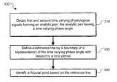
- a machine implemented methodincludes obtaining a first time varying physiological signal and a second time varying physiological signal that relate to biological activity of an organism, the first time varying physiological signal and the second time varying physiological signal forming an analytic pair wherein the analytic pair has a time varying phase angle.
- the methodfurther includes defining a reference line by a boundary of a representation of the time varying phase angle with respect to a time period.
- the methodfurther includes identifying a fiducial point based on the reference line.
- the machine implemented methodcan include approximating the time varying phase angle, wherein the approximation of the varying phase angle ⁇ ⁇ right arrow over (A) ⁇ (t i+K ) can be defined by the function:
- the reference linecan include an isoelectric line defined by a lower boundary of the representation of the time varying phase angle.
- the machine implemented methodcan include calculating a corresponding function to a downslope or an upslope of the representation of the time varying phase angle within the time period; and wherein identifying a fiducial point based on the reference line can include identifying a fiducial point based on an intersection of the corresponding function and the reference line.
- Calculating a corresponding function to a downslope of the representation of the time varying phase anglecan include calculating a tangent line where the downslope can have a minimum slope.
- Calculating a corresponding function to an upslope of the representation of the time varying phase anglecan include calculating a tangent line where the upslope has a maximum slope. Also, identifying a fiducial point based on an intersection of the corresponding function and the reference line can include offsetting the intersection by a constant. Furthermore, calculating a corresponding function to a downslope or an upslope of the representation of the time varying phase angle can include calculating the regression line of the downslope or the upslope of the representation of the time varying phase angle within the time period.
- the machine implementedcan include applying a trigonometric function to the time varying phase angle to create the representation.
- Obtaining a first time varying physiological signalcan include obtaining a sensed signal x(t); and wherein obtaining a second time varying physiological signal ⁇ circumflex over (x) ⁇ (t) can include obtaining a transformation of x(t) to form the analytic pair ⁇ right arrow over (A) ⁇ (t).
- Obtaining a transformation of x(t)can include obtaining a Hilbert Transformation H(x(t)) of the first time varying physiological signal.
- obtaining a transformation of x(t)can include obtaining a derivative of x(t).
- Obtaining a first time varying physiological signalcan include obtaining a first sensed signal based on a first lead configuration; wherein obtaining a second time varying physiological signal can include obtaining a second sensed signal based on a second lead configuration wherein the second sensed signal can be orthogonal to the first; and wherein obtaining the first and second time varying physiological signals can include obtaining the signals from a data storage device. Also, identifying a fiducial point can include identifying one of a T-wave offset, T-wave onset, P-wave offset, P-wave onset, Q-point, R-point, and S-point.
- a systemcan include one or more computers, and a computer-readable storage device having a computer program product encoded therein, the computer program product operable to cause the one or more computers to perform operations which can include: obtaining a first time varying physiological signal and a second time varying physiological signal that relate to biological activity of an organism, the first time varying physiological signal and the second time varying physiological signal forming an analytic pair wherein the analytic pair has a time varying phase angle; defining a reference line by a boundary of a representation of the time varying phase angle with respect to a time period; and identifying a fiducial point based on the reference line.
- Implementationscan include any, all, or none of the following features.
- the computer-readable storage devicecan be further operable to cause the one or more computers to perform operations including: calculating a corresponding function to a downslope or an upslope of the representation of the time varying phase angle within the time period; and wherein identifying a fiducial point based on the reference line can include identifying a fiducial point based on an intersection of the corresponding function and the reference line.
- Calculating a corresponding function to a downslope or an upslope of the representation of the time varying phase anglecan include calculating one of a tangent line, a regression line, and a least square approximation to the downslope or the upslope.
- Identifying a fiducial point based on an intersection of the corresponding function and the reference linecan include offsetting the intersection by a constant.
- the computer-readable storage devicecan be further operable to cause the one or more computers to perform operations including applying a trigonometric function to the time varying phase angle to create the representation.
- the computer-readable storage devicecan be further operable to cause the one or more computers to perform operations can include approximating the time varying phase angle, wherein the approximation of the varying phase angle ⁇ ⁇ right arrow over (A) ⁇ (t i+K ) can be defined by the function:
- Obtaining a first time varying physiological signalcan include obtaining a sensed signal x(t); and wherein obtaining a second time varying physiological signal ⁇ circumflex over (x) ⁇ (t) can include obtaining a transformation of x(t) to form the analytic pair ⁇ right arrow over (A) ⁇ (t).
- Obtaining a transformation of x(t)can include obtaining a Hilbert Transformation H(x(t)) of the first time varying physiological signal.
- Obtaining a transformation of x(t)can include obtaining a derivative of x(t).
- Obtaining a first time varying physiological signalcan include obtaining a first sensed signal based on a first lead configuration; wherein obtaining a second time varying physiological signal can include obtaining a second sensed signal based on a second lead configuration wherein the second sensed signal can be orthogonal to the first; and wherein obtaining the first and second time varying physiological signals can include obtaining the signals from a data storage device.
- Identifying a fiducial pointcan include identifying one of a T-wave offset, T-wave onset, P-wave offset, P-wave onset, Q-point, R-point, and S-point.
- an apparatuscan include circuitry operable to obtain a first time varying physiological signal and a second time varying physiological signal that relate to biological activity of an organism, the first time varying physiological signal and the second time varying physiological signal forming an analytic pair wherein the analytic pair has a time varying phase angle; circuitry operable to define a reference line by a boundary of a representation of the time varying phase angle with respect to a time period; and circuitry operable to identify a fiducial point based on the reference line.
- the apparatuscan include circuitry operable to transmit the identified fiducial points.
- the apparatuscan include circuitry operable to calculate a corresponding function to a downslope or an upslope of the representation of the time varying phase angle within the time period; and wherein the circuitry operable to identify a fiducial point is further operable to identify a fiducial point based on an intersection of the corresponding function and the reference line.
- the circuitry operable to calculate a corresponding function to a downslope or an upslope of the representation of the time varying phase anglecan be further operable to calculate one of a tangent line, a regression line, and a least square approximation to the downslope or the upslope.
- the circuitry operable to identify a fiducial point based on an intersection of the corresponding function and the reference linecan be further operable to offset the intersection by a constant.
- the apparatuscan include circuitry operable to approximate the time varying phase angle, wherein the approximation of the varying phase angle ⁇ ⁇ right arrow over (A) ⁇ (t t+K ) can be defined by the
- the apparatuscan include circuitry operable to apply a trigonometric function to the time varying phase angle to create the representation.
- the circuitry operable to obtain a first time varying physiological signalcan be further operable to obtain a sensed signal x(t); and wherein the circuitry, operable to obtain a second time varying physiological signal, ⁇ circumflex over (x) ⁇ (t) can be further operable to obtain a transformation of x(t) to form the analytic pair ⁇ right arrow over (A) ⁇ (t).
- the circuitry operable to obtain a transformation of x(t)can be further operable to obtain a Hilbert Transformation H(x(t)) of the first time varying physiological signal.
- the circuitry operable to obtain a transformation of x(t)can include obtaining a derivative of x(t).
- the circuitry operable to obtain a first time varying physiological signalcan be further operable to obtain a first sensed signal based on a first lead configuration; wherein the circuitry operable to obtain a second time varying physiological signal can be further operable to obtain a second sensed signal based on a second lead configuration wherein the second sensed signal can be orthogonal to the first; and wherein the circuitry operable to obtain the first and second time varying physiological signals can be further operable to obtain the signals from a data storage device.
- the circuitry operable to identify a fiducial pointcan be further operable to identify one of a T-wave offset, T-wave onset, P-wave offset, P-wave onset, Q-point, R-point, and S-point.
- FIG. 1shows a cardiac monitoring system in which a cardiac signal is monitored for medical purposes.
- FIGS. 2A-2Eshow various graphical representations of ECG signals.
- FIG. 3shows an example procedure for identifying fiducial points.
- FIG. 4shows a graphical representation of identification of a T-wave offset.
- FIG. 5shows an example procedure for identifying a T-wave offset.
- the present applicationdescribes systems and techniques relating to automated analysis of a physiological signal of an organism, including identification of a reference line such as an isoelectric line and identification of fiducial points for such a physiological signal.
- the physiological signalcan be a cardiac signal, such as an ECG signal, a brain signal, such as an electroencephalogram (EEG) signal, a respiratory signal, a blood pressure signal, or other signals from an organism.
- ECGelectroencephalogram
- the signal(s)can be obtained directly, for example by monitoring heart activity of a human patient as described further below, or the signal(s) can be obtained indirectly from another device or system.
- the signal processing and analysis described hereincan be performed in real-time as the signals are acquired and/or on stored signals retrieved from a database or other electronic storage devices.
- the systems and techniques described hereenable partial reconstruction of heart dynamics from one-lead and multiple-lead systems, and can allow a cardiac monitoring system to accurately locate fiducial points such as P-wave onset, P-wave offset, T-wave onset, T-wave offset, Q-point, R-point, and S-point.
- the systemcan assist in detecting a physiological condition, such as ventricular fibrillation, premature ventricular contraction (PVC), heart block conditions, long QT syndrome or QT prolongation, etc.
- PVCpremature ventricular contraction
- itcan be very important to accurately identify the location of fiducial points.
- accurate identification of fiducial pointscan be important in the calculation of the PR or QT intervals. Small variations of even 5 ms of the QT interval can be significant.
- Reconstructing the dynamics of the heart from the ECG signalscan result in more accurate analysis of the heart's activity.
- the systems and techniques belowcan result in improved analysis without requiring significant additional computational resources.
- FIG. 1shows a cardiac monitoring system 100 in which a cardiac signal is monitored for medical purposes.
- a patient 110e.g., a human patient, including potentially a healthy patient for whom cardiac monitoring is nonetheless deemed appropriate
- the cardiac monitoring apparatus 120can be composed of one or more devices, such as a processing device and a sensing device.
- the sensing devicecan include one or more leads 125 , which can receive electrical signals through body surface electrodes. These leads (as shown, for example, two leads e.g., silver/silver chloride electrodes) can be positioned at defined locations to aid in monitoring the electrical activity of the heart.
- the term “lead”should be understood as including both a device that is subject to a potential difference that yields a voltage signal, such as an electrode that produces an ECG signal, and a conductor that forms a signal path to the apparatus 120 (e.g. to a signal amplifier in the apparatus 120 ).
- the cardiac monitoring apparatus 120can communicate with a monitoring station 140 (e.g., a computer in a monitoring center) via a communications channel 130 .
- the cardiac monitoring apparatus 120can include one or more sensing, calibration, signal processing, control, data storage, and transmission devices suitable for generating and processing the cardiac signal, as well as for relaying all or a portion of the cardiac signal over the communications channel 130 .
- the communications channel 130can be part of a communications network and can include any suitable medium for data transmission, including wired and wireless media suitable for carrying optical and/or electrical signals. Wireless communications by the apparatus 120 can employ a suitable antenna 135 as illustrated.
- the cardiac monitoring apparatus 120can communicate sensed cardiac signals, cardiac event information (e.g., real-time heart rate data), and additional physiological and/or other information to the monitoring station 140 .
- the cardiac monitoring apparatus 120can include an implantable medical device, such as an implantable cardiac defibrillator and an associated transceiver or pacemaker and an associated transceiver, or an external monitoring device that the patient wears or that is installed near the patient.
- the cardiac monitoring apparatus 120can be implemented using, for example, the CardioNet Mobile Cardiac Outpatient Telemetry (MCOT) device, which is commercially available and provided by CardioNet, Inc. of San Diego, Calif.
- MCOTCardioNet Mobile Cardiac Outpatient Telemetry
- the monitoring station 140can include a receiver element for receiving transmitted signals, as well as various data processing and storage elements for extracting and storing information carried by transmissions regarding the state of the patient 110 .
- the monitoring station 140can be located in the same general location (e.g., in the same room, building or health care facility) as the monitoring apparatus 120 , or at a remote location.
- the monitoring station 140can include a display and a processing system.
- a system operator 150e.g., a health care provider such as a doctor or a cardiovascular technician
- the system operator 150can use the monitoring station 140 to change operational settings of the cardiac monitoring apparatus 120 remotely during active cardiac monitoring of the patient 110 .
- the cardiac monitoring apparatus 120 and/or the monitoring station 140can use the systems and techniques described herein to identify physiological information concerning the patient 110 .
- Thiscan include signal processing and analysis on both an actively received signal (which can be cached in memory at the station 140 ) and prior signals stored in a storage medium or device such as in a database 145 .
- an actively received signalwhich can be cached in memory at the station 140
- prior signalsstored in a storage medium or device such as in a database 145 .
- historical signal information for a personcan be used in conjunction with the systems and techniques described herein to improve analysis of currently acquired signals, and can facilitate heart beat classification and characterization of physiological conditions, which can assist a clinician or physician in making an appropriate diagnosis and prescribing an appropriate treatment.
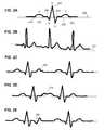
- FIGS. 2A-2Eshow various graphical representations of ECG signals.
- FIG. 2Ashows a graphical representation of a normal ECG signal. As shown, portions of an ECG signal have been identified using the conventional lettering: P, Q, R, S, and T (e.g. P identifies the P-wave, and T identifies the T-wave etc.).
- Isoelectric line 250represents the baseline voltage of the ECG signal.
- Various fiducial pointscan be identified on the ECG signal.
- the P-wavehas a P-wave onset 210 and a P-wave offset 220 .
- the T-wavehas a T-wave onset 230 and a T-wave offset 240 .
- Other fiducial pointscan include, for example, a Q-point 246 which is the beginning of ventricular depolarization, an R-point 247 which is the peak of the QRS complex, and an S-point 248 which is the end of ventricular depolarization.
- these onsets and offsetsoccur along the isoelectric line 250 .
- traditional approaches to identification of the fiducial points and the isoelectric linecan be affected by various physiological factors such as by baseline wandering ( FIG. 2B ), T-U wave collision 260 ( FIG. 2C ), T-P wave collision 270 ( FIG. 2D ), abnormal T-wave such as an inverted signal 280 ( FIG. 2E ), etc.
- FIG. 3shows an example procedure 300 for identifying fiducial points.
- first and second time varying signals related to biological activity of an organismare obtained.
- the time varying signalscan be any two vectors related to biological activity that have a time varying phase angle.
- the first time varying signalcan be denoted by x(t).
- the second time varying signalis also related to the same biological activity of the organism as the first time varying signal and can be denoted by ⁇ circumflex over (x) ⁇ (t).
- the first and second time varying signalsform an analytic pair, which can be denoted by ⁇ right arrow over (A) ⁇ (t).
- the analytic pairhas a time varying phase angle, which can be denoted by ⁇ right arrow over ( ⁇ ) ⁇ (t).
- the first and second time varying signalscan be obtained in real-time (subject to communication and caching delays) or obtained from a storage device. Based on a phase property of a time varying phase angle of such an analytic pair, a representation of time vary phase angle with respect to time will have a mathematically defined boundary.
- the first and second time varying signalscan be sensed ECG signals representative of a cardiac activity of a patient.
- a multiple lead configurationcan be used such that a second time varying signal can be a sensed ECG signal for the same cardiac activity as the first time varying ECG signal but obtained from a different lead field.
- the multiple lead configurationcan be configured such that the sensed second time varying ECG signal is generally orthogonal to the sensed first time varying ECG signal.
- One such multiple lead configurationis the Frank electrocardiographic lead system which can achieve, to a good approximation, lead vectors that are mutually orthogonal.
- the first time varying signalcan be obtained from one of these mutually orthogonal vectors and the second time varying signal can be obtained from another of these mutually orthogonal vectors.
- the second time varying signalcan be obtained by obtaining a transformation of the first time varying signal.
- the transformation of x(t)can be a derivative (e.g. first derivative (d/dx), second derivative (d 2 /dx 2 ), etc.) of the function x(t).
- the transformation of x(t)can be a Hilbert transform, H(x(t)).
- Other transformscan be obtained as well, such as a trigonometric function of x(t), Laplace transform of x(t), a Fourier transform of x(t), etc.
- the time varying, phase angle of the analytic paircan be approximated by computing the changes of ⁇ right arrow over (A) ⁇ (t), where ⁇ circumflex over (x) ⁇ (t) is the second time varying signal (which can be a transformation of x(t)), where i is the current sample, where K is K samples away, and where ⁇ right arrow over (A) ⁇ (t i+k ) is the change of the two vectors ((x(t i ), ⁇ circumflex over (x) ⁇ (t i )) and (x(t i+K ), ⁇ circumflex over (x) ⁇ (t i+K )).
- An approximation of the time varying phase angle, ⁇ ⁇ right arrow over (A) ⁇ (t t+K )can be defined by the function:
- a reference lineis defined by a boundary of a representation of the time varying phase angle with respect to a time period.
- the time periodcan be the time period for a portion of the ECG signal that is being examined.
- a time varying phase or angular changedoes not involve an amplitude component therefore the lower boundary of a representation of the time varying phase angle with respect to time is not affected by baseline wandering.
- the representation of the time varying phase anglecan include, for example, a plot of the time varying phase angle with respect to the time period.
- the representation of the time varying phase anglecan also include an approximation of the time varying phase angle with respect to the time period. Because the phase changes are bounded by
- a fiducial pointcan be identified based on the reference line.
- the time varying phase anglecan be represented by a series of data points rather than a continuous line.
- a fiducial pointcan be identified at the time that corresponds to the point that comes closest to or intersects with the reference line. For example, when determining a fiducial point along the isoelectric line such as offset or onset, the fiducial point can be identified as the time associated with the point on the representation of the time varying phase angle that comes closest to or intersects with the reference line along the lower boundary.
- a peak of an ECG signalsuch as an R-point, P-peak, or a T-peak can be identified at the time associated with the point on the representation of the of the time varying phase angle that comes closest to or intersects with the reference line along the upper boundary.
- the fiducial pointcan be identified based on an intersection of a reference line with a corresponding function to a downslope or an upslope of the representation of the time varying phase angle.
- a corresponding functioncan be a line or curve calculated for a downslope or an upslope of the representation.
- a corresponding functioncan be calculated for the downslope of a T-wave.
- a T-wave offsetcan be identified based on the intersection of the corresponding function with the reference line along the lower boundary of the representation of the time varying phase angle.
- a T-wave peakcan be identified based on the intersection of the corresponding function with the reference line along the upper boundary of the representation of the time varying phase angle.
- a corresponding functioncan be calculated for the upslope of a T-wave.
- a corresponding functioncan be calculated for a downslope of a P-wave.
- a corresponding functioncan be calculated for an upslope of a P-wave.
- calculating the corresponding functioncan include calculating the line tangent to the point where the downslope has a minimum slope.
- calculating the corresponding functioncan include calculating the line tangent to the point where the upslope has a maximum slope.
- a least square fittingcan be applied around the region where a downslope has a maximum slope or around the region where an upslope has a maximum.
- An intersection of the corresponding function and the reference lineis identified in order to determine a fiducial point. Identifying a fiducial point based on an intersection of the corresponding function can include offsetting the intersection of the corresponding function with the reference line by a constant.
- the constantcan be determined using an average variation of detected values of like intersections from the true fiducial point. For example, over time, it can be determined by the monitoring apparatus, or some other automated apparatus, or by a medical profession that there is a variance between the actual fiducial point and the intersection of the corresponding function with the reference line. The measured intersection can be set-off by the average variance to identify the fiducial point.
- mathematical transformationscan impose a low pass filter effect moving the intersect of the corresponding function away from the true fiducial point.
- the variationcan be constant which can be calculated mathematically or by detection.
- the monitoring systemcan automatically or by feedback from a medical technician update the constant used to determine the fiducial points based on data received from monitoring a patient or patients.
- offsetting the intersectionmay not be necessary when determining a fiducial point. For example, identifying an isoelectric line at the lower boundary of the representation of the time varying phase angle can provide consistency between measurements. So, offsetting the intersection may not be necessary when determining fiducial points for use in calculating dynamic changes of intervals such as ⁇ QT.
- FIG. 4shows a graphical representation of identification of a T-wave offset.
- Graph 400shows a graphical representation of an ECG signal 410 and a graphical representation of a time-varying phase angle 450 for a given time period. Time is represented by the x-axis 420 .
- the y-axis 415represents both volts for the amplitude of the ECG signal 410 and a trigonometric value for the representation of the time varying phase angle 450 .
- the ECG signal 410is affected by base-line wandering.
- the ECG signal 410is the first time varying signal of an analytic pair.
- the second time varying signalis a Hilbert transformation of the ECG signal.
- the analytic pairhas a time varying phase angle, which is graphically represented by 450 .
- the graph 400shows a graphical representation of the upper boundary 453 and the lower bounder 455 .
- Graph 400also shows a graphical representation of a corresponding function 460 to a downslope of the representation of the time varying phase angle that corresponds with a downslope of the T-wave.
- Corresponding function 460is the tangent line to the point where the downslope has a minimum slope 470 .
- the T-wave offsetcan be identified based on an intersection of the corresponding function 460 with the isoelectric line 455 .
- a graphical representation of the intersectionis shown at 480 .
- FIG. 4shows a graphical representation of how a fiducial point is determined, it by no means should be inferred that a graphical representation is necessary to identify a reference line or a fiducial point according to the methods and procedures described in this application.
- a representation of the time varying phase angle with respect to a time periodcan be a set of data points representative of the time varying phase angle for a time period stored in a storage device.
- a representation similar the graphical representation of corresponding function 460can also be used for identification of other fiducial points such as T-wave onset, P-wave offset, P-wave onset, Q-point, R-point, S-point, etc.
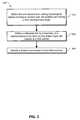
- FIG. 5shows an example procedure 500 for identifying a T-wave offset.
- a procedure similar to the procedure in FIG. 5can be performed for identification of other fiducial points.
- a time varying ECG signalis obtained.
- the ECG signalcan be obtained real-time from a patient or from a data storage device.
- first and second adjacent R peaksare identified.
- the second time varying signalcan be obtained by applying a transformation to portion of the ECG signal between the first and second R peak. In other examples, the second time varying signal can be obtained for the time period between the first and second R peaks from an ECG signal obtained from a different leads configuration than was used to obtain for the first time varying ECG signal.
- an isoelectric lineis defined by the lower boundary of a representation of the time varying phase angle with respect to the time period between the first and second R peaks.
- a T-wave phase peakis located between the first and second peaks using a preset algorithm.
- a corresponding function to a downslope from the T-wave phase peakis calculated.
- the intersection of the corresponding function with the isoelectric lineis identified. Based on the intersection, the T-wave offset is identified. The intersection itself can be identified as the T-wave offset. In other examples, the intersection can be altered by a pre-set amount to determine the T-wave offset.
- the disclosed systems, techniques, and all of the functional operations described and illustrated in this specificationcan be implemented in digital electronic circuitry, or in computer hardware, firmware, software, or in combinations of the forgoing.
- one or more computers and/or circuitrycan be operable to or configured and arranged to perform the functions and techniques disclosed herein.
- Apparatuses and/or systemscan be implemented using a software product (e.g., a computer program product) tangibly embodied in a machine-readable storage device for execution by a programmable processor, and processing operations can be performed by a programmable processor executing a program of instructions to perform functions by operating on input data and generating output.
- the systemcan be implemented advantageously in one or more software programs that are executable on a programmable system.
- This programmable systemcan include the following: 1) at least one programmable processor coupled to receive data and instructions from, and to transmit data and instructions to, a data storage system; 2) at least one input device; and 3) at least one output device.
- each software programcan be implemented in a high-level procedural or object-oriented programming language, or in assembly or machine language if desired; and in any case, the language can be a compiled or an interpreted language.
- suitable processorsinclude, by way of example, both general and special purpose microprocessors.
- a processorwill receive instructions and data from a read-only memory, a random access memory, and/or a machine-readable signal (e.g., a digital signal received through a network connection).
- the essential elements of a computerare a processor for performing instructions and one or more memory devices for storing instructions and data.
- a computerwill include one or more mass storage devices for storing data files. Such devices can include magnetic disks, such as internal hard disks and removable disks, magneto-optical disks, and optical disks.
- Storage devices suitable for tangibly embodying software program instructions and datainclude all forms of non-volatile memory, including, by way of example, the following: 1) semiconductor memory devices, such as EPROM (electrically programmable read-only memory); EEPROM (electrically erasable programmable read-only memory) and flash memory devices; 2) magnetic disks such as internal hard disks and removable disks; 3) magneto-optical disks; and 4) CD-ROM disks. Any of the foregoing can be supplemented by, or incorporated in, ASICs (application-specific integrated circuits).
- ASICsapplication-specific integrated circuits
- a communications networksuch as a wired or wireless network.
- Examples of communication networksinclude, e.g., a local area network (“LAN”), a wide area network (“WAN”), the Internet or any combinations of such.
- the systemcan be implemented on a computer system having a display device such as a monitor or LCD (liquid crystal display) screen for displaying information to the user and a keyboard and a pointing device such as a mouse or a trackball by which the user can provide input to the computer system.
- a display devicesuch as a monitor or LCD (liquid crystal display) screen for displaying information to the user
- a keyboard and a pointing devicesuch as a mouse or a trackball by which the user can provide input to the computer system.
- the computer systemcan be programmed to provide a graphical user interface through which computer programs interact with users.
Landscapes
- Health & Medical Sciences (AREA)
- Life Sciences & Earth Sciences (AREA)
- Engineering & Computer Science (AREA)
- Cardiology (AREA)
- Surgery (AREA)
- Medical Informatics (AREA)
- Veterinary Medicine (AREA)
- Physics & Mathematics (AREA)
- Public Health (AREA)
- Biophysics (AREA)
- Pathology (AREA)
- Biomedical Technology (AREA)
- Heart & Thoracic Surgery (AREA)
- General Health & Medical Sciences (AREA)
- Molecular Biology (AREA)
- Animal Behavior & Ethology (AREA)
- Computer Vision & Pattern Recognition (AREA)
- Psychiatry (AREA)
- Physiology (AREA)
- Signal Processing (AREA)
- Artificial Intelligence (AREA)
- Measurement And Recording Of Electrical Phenomena And Electrical Characteristics Of The Living Body (AREA)
Abstract
Description
where x(t) includes the first time varying physiological signal and {circumflex over (x)}(t) includes the second time varying physiological signal, x(t) and {circumflex over (x)}(t) forming the analytic pair {right arrow over (A)}(t); where i is a current sample; where K is K samples away; and where Δ{right arrow over (A)}(ti+k) is the change of the two vectors ((x(ti), {circumflex over (x)}(ti)) and (x(ti+K), {circumflex over (x)}(ti+K)). The reference line can include an isoelectric line defined by a lower boundary of the representation of the time varying phase angle. The machine implemented method can include calculating a corresponding function to a downslope or an upslope of the representation of the time varying phase angle within the time period; and wherein identifying a fiducial point based on the reference line can include identifying a fiducial point based on an intersection of the corresponding function and the reference line. Calculating a corresponding function to a downslope of the representation of the time varying phase angle can include calculating a tangent line where the downslope can have a minimum slope.
includes the first time varying physiological signal and {circumflex over (x)}(t) includes the second time varying physiological signal, x(t) and {circumflex over (x)}(t) forming the analytic pair {right arrow over (A)}(t); where i can be a current sample; where K can be K samples away; and where Δ{right arrow over (A)}(ti+k) is the change of the two vectors ((x(ti), {circumflex over (x)}(ti)) and (x(ti+K), {circumflex over (x)}(ti+K)). Obtaining a first time varying physiological signal can include obtaining a sensed signal x(t); and wherein obtaining a second time varying physiological signal {circumflex over (x)}(t) can include obtaining a transformation of x(t) to form the analytic pair {right arrow over (A)}(t). Obtaining a transformation of x(t) can include obtaining a Hilbert Transformation H(x(t)) of the first time varying physiological signal. Obtaining a transformation of x(t) can include obtaining a derivative of x(t). Obtaining a first time varying physiological signal can include obtaining a first sensed signal based on a first lead configuration; wherein obtaining a second time varying physiological signal can include obtaining a second sensed signal based on a second lead configuration wherein the second sensed signal can be orthogonal to the first; and wherein obtaining the first and second time varying physiological signals can include obtaining the signals from a data storage device. Identifying a fiducial point can include identifying one of a T-wave offset, T-wave onset, P-wave offset, P-wave onset, Q-point, R-point, and S-point.
where x(t) includes the first time varying physiological signal and {circumflex over (x)}(t) includes the second time varying physiological signal, x(t) and {circumflex over (x)}(t) forming the analytic pair {right arrow over (A)}(t); where i is a current sample; where K is K samples away; and where Δ{right arrow over (A)}(ti+k) is the change of the two vectors ((x(ti), {circumflex over (x)}(ti)) and (x(ti+K), {circumflex over (x)}(ti+K)). The apparatus can include circuitry operable to apply a trigonometric function to the time varying phase angle to create the representation. The circuitry operable to obtain a first time varying physiological signal can be further operable to obtain a sensed signal x(t); and wherein the circuitry, operable to obtain a second time varying physiological signal, {circumflex over (x)}(t) can be further operable to obtain a transformation of x(t) to form the analytic pair {right arrow over (A)}(t). The circuitry operable to obtain a transformation of x(t) can be further operable to obtain a Hilbert Transformation H(x(t)) of the first time varying physiological signal. The circuitry operable to obtain a transformation of x(t) can include obtaining a derivative of x(t).
the plot of the time varying phase angle or an approximation of the time varying phase angle with respect to the time period is bound by
(or in degrees [−90°, 90°]). In this case, a reference line, such as an isoelectric line can be defined by the lower boundary, y=−π/2. A reference line can also be defined by the upper bounder y=−π/2. The representation can also be created by applying a trigonometric function to the time varying phase angle or an approximation of the time varying phase angle for the time period. In which case, the time varying phase angle is bounded by [−1, 1] and the reference line can be defined by the lower boundary y=−1, or the upper boundary y=1.
Claims (37)
Priority Applications (5)
| Application Number | Priority Date | Filing Date | Title |
|---|---|---|---|
| US12/368,976US8200319B2 (en) | 2009-02-10 | 2009-02-10 | Locating fiducial points in a physiological signal |
| CA2752012ACA2752012A1 (en) | 2009-02-10 | 2010-02-09 | Locating fiducial points in a physiological signal |
| PCT/US2010/023667WO2010093641A1 (en) | 2009-02-10 | 2010-02-09 | Locating fiducial points in a physiological signal |
| DK10741634.9TDK2395910T3 (en) | 2009-02-10 | 2010-02-09 | LOCATION OF FIDUCIAL POINTS IN A PHYSIOLOGICAL SIGNAL |
| EP10741634.9AEP2395910B1 (en) | 2009-02-10 | 2010-02-09 | Locating fiducial points in a physiological signal |
Applications Claiming Priority (1)
| Application Number | Priority Date | Filing Date | Title |
|---|---|---|---|
| US12/368,976US8200319B2 (en) | 2009-02-10 | 2009-02-10 | Locating fiducial points in a physiological signal |
Publications (2)
| Publication Number | Publication Date |
|---|---|
| US20100204599A1 US20100204599A1 (en) | 2010-08-12 |
| US8200319B2true US8200319B2 (en) | 2012-06-12 |
Family
ID=42540988
Family Applications (1)
| Application Number | Title | Priority Date | Filing Date |
|---|---|---|---|
| US12/368,976Active2030-11-18US8200319B2 (en) | 2009-02-10 | 2009-02-10 | Locating fiducial points in a physiological signal |
Country Status (5)
| Country | Link |
|---|---|
| US (1) | US8200319B2 (en) |
| EP (1) | EP2395910B1 (en) |
| CA (1) | CA2752012A1 (en) |
| DK (1) | DK2395910T3 (en) |
| WO (1) | WO2010093641A1 (en) |
Cited By (26)
| Publication number | Priority date | Publication date | Assignee | Title |
|---|---|---|---|---|
| US9173670B2 (en) | 2013-04-08 | 2015-11-03 | Irhythm Technologies, Inc. | Skin abrader |
| US9226679B2 (en) | 2010-05-21 | 2016-01-05 | Medicomp, Inc. | Systems and methods for interelectrode distance optimization in a retractable multi-use cardiac monitor |
| US9241649B2 (en) | 2010-05-12 | 2016-01-26 | Irhythm Technologies, Inc. | Device features and design elements for long-term adhesion |
| US9585584B2 (en) | 2010-05-21 | 2017-03-07 | Medicomp, Inc. | Physiological signal monitor with retractable wires |
| US9597004B2 (en) | 2014-10-31 | 2017-03-21 | Irhythm Technologies, Inc. | Wearable monitor |
| US9782132B2 (en) | 2012-10-07 | 2017-10-10 | Rhythm Diagnostic Systems, Inc. | Health monitoring systems and methods |
| US9876791B2 (en) | 2014-12-30 | 2018-01-23 | Samsung Electronics Co., Ltd. | Method and apparatus for authenticating user based on biosignal |
| US10244949B2 (en) | 2012-10-07 | 2019-04-02 | Rhythm Diagnostic Systems, Inc. | Health monitoring systems and methods |
| US10271754B2 (en) | 2013-01-24 | 2019-04-30 | Irhythm Technologies, Inc. | Physiological monitoring device |
| USD850626S1 (en) | 2013-03-15 | 2019-06-04 | Rhythm Diagnostic Systems, Inc. | Health monitoring apparatuses |
| WO2019241407A1 (en) | 2018-06-12 | 2019-12-19 | Braemar Manufacturing, Llc | Predicting atrial fibrillation or stroke using p-wave analysis |
| US10610159B2 (en) | 2012-10-07 | 2020-04-07 | Rhythm Diagnostic Systems, Inc. | Health monitoring systems and methods |
| USD921204S1 (en) | 2013-03-15 | 2021-06-01 | Rds | Health monitoring apparatus |
| US11083371B1 (en) | 2020-02-12 | 2021-08-10 | Irhythm Technologies, Inc. | Methods and systems for processing data via an executable file on a monitor to reduce the dimensionality of the data and encrypting the data being transmitted over the wireless network |
| US11246523B1 (en) | 2020-08-06 | 2022-02-15 | Irhythm Technologies, Inc. | Wearable device with conductive traces and insulator |
| US11273283B2 (en) | 2017-12-31 | 2022-03-15 | Neuroenhancement Lab, LLC | Method and apparatus for neuroenhancement to enhance emotional response |
| US11350864B2 (en) | 2020-08-06 | 2022-06-07 | Irhythm Technologies, Inc. | Adhesive physiological monitoring device |
| US11364361B2 (en) | 2018-04-20 | 2022-06-21 | Neuroenhancement Lab, LLC | System and method for inducing sleep by transplanting mental states |
| US11452839B2 (en) | 2018-09-14 | 2022-09-27 | Neuroenhancement Lab, LLC | System and method of improving sleep |
| US11717686B2 (en) | 2017-12-04 | 2023-08-08 | Neuroenhancement Lab, LLC | Method and apparatus for neuroenhancement to facilitate learning and performance |
| US11723579B2 (en) | 2017-09-19 | 2023-08-15 | Neuroenhancement Lab, LLC | Method and apparatus for neuroenhancement |
| US11786694B2 (en) | 2019-05-24 | 2023-10-17 | NeuroLight, Inc. | Device, method, and app for facilitating sleep |
| US11903700B2 (en) | 2019-08-28 | 2024-02-20 | Rds | Vital signs monitoring systems and methods |
| US12109047B2 (en) | 2019-01-25 | 2024-10-08 | Rds | Health monitoring systems and methods |
| USD1063079S1 (en) | 2021-08-06 | 2025-02-18 | Irhythm Technologies, Inc. | Physiological monitoring device |
| US12280219B2 (en) | 2017-12-31 | 2025-04-22 | NeuroLight, Inc. | Method and apparatus for neuroenhancement to enhance emotional response |
Families Citing this family (7)
| Publication number | Priority date | Publication date | Assignee | Title |
|---|---|---|---|---|
| US8301236B2 (en) | 2009-05-22 | 2012-10-30 | Biomedical Systems Corporation | System and method for high resolution wireless full disclosure ECG episode monitoring and analysis |
| US9084548B2 (en) | 2011-11-07 | 2015-07-21 | Braemar Manufacturing, Llc | Ventricular fibrillation detection |
| CN103006205B (en)* | 2012-12-29 | 2014-07-02 | 重庆邮电大学 | Device and method for electrocardiosignal baseline recognition |
| US20150173638A1 (en)* | 2013-12-23 | 2015-06-25 | Cerner Innovation, Inc. | Direct comparison of multiple healthcare waves |
| EP3892198B1 (en)* | 2014-11-14 | 2024-03-06 | ZOLL Medical Corporation | Medical premonitory event estimation |
| US9986932B2 (en)* | 2014-11-17 | 2018-06-05 | Medtronic Monitoring, Inc. | QT interval determination methods and related devices |
| CN115590525B (en)* | 2022-10-28 | 2025-07-29 | 众阳健康科技集团有限公司 | Electrocardiogram vector ring rotation direction identification method and system |
Citations (84)
| Publication number | Priority date | Publication date | Assignee | Title |
|---|---|---|---|---|
| US4622979A (en) | 1984-03-02 | 1986-11-18 | Cardiac Monitoring, Inc. | User-worn apparatus for monitoring and recording electrocardiographic data and method of operation |
| US4630204A (en) | 1984-02-21 | 1986-12-16 | Mortara Instrument Inc. | High resolution ECG waveform processor |
| US4646754A (en) | 1985-02-19 | 1987-03-03 | Seale Joseph B | Non-invasive determination of mechanical characteristics in the body |
| US4920489A (en) | 1987-08-14 | 1990-04-24 | Cardiodata Inc. | Apparatus and method for solid state storage of episodic signals |
| US4938228A (en) | 1989-02-15 | 1990-07-03 | Righter William H | Wrist worn heart rate monitor |
| US4951681A (en) | 1988-11-14 | 1990-08-28 | Mortara Instrument | Electrocardiographic recording method and apparatus |
| US4958641A (en) | 1989-03-10 | 1990-09-25 | Instromedix, Inc. | Heart data monitoring method and apparatus |
| US4977899A (en) | 1989-03-10 | 1990-12-18 | Instromedix, Inc. | Heart data monitoring method and apparatus |
| US5047930A (en) | 1987-06-26 | 1991-09-10 | Nicolet Instrument Corporation | Method and system for analysis of long term physiological polygraphic recordings |
| USD326716S (en) | 1990-02-22 | 1992-06-02 | Mortara Instrument | Medical cable |
| US5191891A (en) | 1991-09-10 | 1993-03-09 | Ralin, Inc. | Portable ECG monitor/recorder |
| US5197479A (en) | 1991-05-13 | 1993-03-30 | Mortara Instrument | Automatic electrode channel impedance measurement system for egg monitor |
| US5226425A (en) | 1991-09-10 | 1993-07-13 | Ralin, Inc. | Portable ECG monitor/recorder |
| US5421342A (en) | 1991-01-18 | 1995-06-06 | Mortara Instrument, Inc. | Filter apparatus and method for reducing signal noise using multiple signals obtained from a single source |
| US5522393A (en) | 1994-05-24 | 1996-06-04 | Duke University | Multi-dimensional real-time ultrasonic blood flow imaging apparatus and method |
| US5522396A (en) | 1992-05-12 | 1996-06-04 | Cardiac Telecom Corporation | Method and system for monitoring the heart of a patient |
| US5546950A (en) | 1994-07-06 | 1996-08-20 | Mortara Instrument, Inc. | Electrocardiograpic patient lead cable apparatus |
| US5560367A (en) | 1993-08-13 | 1996-10-01 | Siemens Aktiengesellschaft | Method for high-resolution spectral analysis in multi channel observations using a singular valve decomposition (SVD) matrix technique |
| US5581369A (en) | 1992-09-25 | 1996-12-03 | Ralin, Inc. | Apparatus and method for communicating electrocardiographic data to a facsimile machine |
| US5596993A (en) | 1994-09-21 | 1997-01-28 | Beth Israel Hospital | Fetal data processing system and method |
| USD377983S (en) | 1995-09-13 | 1997-02-11 | Mohamed Sabri | Cardiac monitor |
| US5609158A (en) | 1995-05-01 | 1997-03-11 | Arrhythmia Research Technology, Inc. | Apparatus and method for predicting cardiac arrhythmia by detection of micropotentials and analysis of all ECG segments and intervals |
| US5634468A (en) | 1992-04-03 | 1997-06-03 | Micromedical Industries Limited | Sensor patch and system for physiological monitoring |
| US5645069A (en) | 1994-05-26 | 1997-07-08 | Lg Electronics Inc. | System for and method of analyzing electrocardiograms employing chaos techniques |
| US5678562A (en) | 1995-11-09 | 1997-10-21 | Burdick, Inc. | Ambulatory physiological monitor with removable disk cartridge and wireless modem |
| US5704351A (en) | 1995-02-28 | 1998-01-06 | Mortara Instrument, Inc. | Multiple channel biomedical digital telemetry transmitter |
| US5730143A (en) | 1996-05-03 | 1998-03-24 | Ralin Medical, Inc. | Electrocardiographic monitoring and recording device |
| US5810014A (en) | 1997-03-25 | 1998-09-22 | Davis; Dennis W. | Method and system for detection of physiological conditions |
| US5827195A (en) | 1997-05-09 | 1998-10-27 | Cambridge Heart, Inc. | Electrocardiogram noise reduction using multi-dimensional filtering |
| US5931791A (en) | 1997-11-05 | 1999-08-03 | Instromedix, Inc. | Medical patient vital signs-monitoring apparatus |
| USD414870S (en) | 1998-01-02 | 1999-10-05 | Instromedix, Inc. | Vital signs monitor |
| US5966692A (en) | 1992-05-12 | 1999-10-12 | Telemed Technologies International Corporation | Method and system for monitoring the heart of a patient |
| US6024701A (en) | 1998-08-27 | 2000-02-15 | T.A.O. Medical Technologies Ltd. | Method of and system for estimating placenta and fetus well being using system identification techniques |
| US6028428A (en) | 1998-04-09 | 2000-02-22 | Cunningham; Charles H. | Multiband selective RF pulse construction for NMR measurement sequences |
| US6069975A (en) | 1996-05-15 | 2000-05-30 | Siemsn Aktiengesellschaft | Method and device for processing a signal |
| US6076015A (en) | 1998-02-27 | 2000-06-13 | Cardiac Pacemakers, Inc. | Rate adaptive cardiac rhythm management device using transthoracic impedance |
| US6102856A (en) | 1997-02-12 | 2000-08-15 | Groff; Clarence P | Wearable vital sign monitoring system |
| US6216031B1 (en) | 1998-02-11 | 2001-04-10 | Marquette Hellige Gmbh | Apparatus for enhancing signals in ECGs artefacts |
| US6269263B1 (en) | 1998-12-11 | 2001-07-31 | Riken | Method for estimating heart rate variability and apparatus for embodying estimation |
| US6278961B1 (en) | 1997-07-02 | 2001-08-21 | Nonlinear Solutions, Inc. | Signal and pattern detection or classification by estimation of continuous dynamical models |
| US6287252B1 (en) | 1999-06-30 | 2001-09-11 | Monitrak | Patient monitor |
| US6340346B1 (en) | 1999-11-26 | 2002-01-22 | T.A.O. Medical Technologies Ltd. | Method and system for system identification of physiological systems |
| US6366871B1 (en) | 1999-03-03 | 2002-04-02 | Card Guard Scientific Survival Ltd. | Personal ambulatory cellular health monitor for mobile patient |
| US6368283B1 (en) | 2000-09-08 | 2002-04-09 | Institut De Recherches Cliniques De Montreal | Method and apparatus for estimating systolic and mean pulmonary artery pressures of a patient |
| US6370437B1 (en) | 1998-06-23 | 2002-04-09 | Nortel Networks Limited | Dynamic prediction for process control |
| US6377843B1 (en) | 2000-03-03 | 2002-04-23 | Paceart Associates, L.P. | Transtelephonic monitoring of multi-channel ECG waveforms |
| US6381559B1 (en) | 1996-08-12 | 2002-04-30 | The United States Of America As Represented By The Administrator Of The National Aeronautics And Space Administration | Empirical mode decomposition apparatus, method and article of manufacture for analyzing biological signals and performing curve fitting |
| US6400996B1 (en) | 1999-02-01 | 2002-06-04 | Steven M. Hoffberg | Adaptive pattern recognition based control system and method |
| US6401057B1 (en) | 1997-07-02 | 2002-06-04 | Nonlinear Solutions, Inc. | Detection and classification system for analyzing deterministic properties of data using correlation parameters |
| US20020095099A1 (en) | 2000-04-27 | 2002-07-18 | Centre National De La Recherche Scientificque | Method and device for the medical monitoring in real time of a patient from the analysis of electro-encephalograms, application of this method to characterize and to differentiate between physiological or pathologial conditions, and a method for anticipating epileptic seizures in real time |
| US20020128804A1 (en) | 1998-03-03 | 2002-09-12 | Jacob Geva | Personal ambulatory cellular health monitor |
| US20030009399A1 (en) | 2001-03-22 | 2003-01-09 | Boerner Sean T. | Method and system to identify discrete trends in time series |
| US6507749B1 (en) | 2001-07-18 | 2003-01-14 | Sunnybrook And Women's College | Method and apparatus for tracking the motion of fluid and determining a velocity spectrum thereof from MR data acquired in a single cycle |
| US20030028442A1 (en) | 2001-08-06 | 2003-02-06 | Craig Wagstaff | Method of supplying heart screening services directly to a customer |
| US6537233B1 (en) | 2000-11-06 | 2003-03-25 | University Technologies International Inc. | Auditory display of knee joint vibration signals |
| US20030065633A1 (en) | 2000-01-31 | 2003-04-03 | Raft Neuneier | Configuration of interconnected arithmetic elements, and method for the computer-aided determination of a second state of a system in a first state space from a first state of the system in the first state space |
| US20030069487A1 (en) | 2001-10-10 | 2003-04-10 | Mortara Instrument, Inc. | Method and apparatus for pulse oximetry |
| US20030069486A1 (en) | 2001-10-05 | 2003-04-10 | Mortara Instrument, Inc. | Low power pulse oximeter |
| US6561986B2 (en) | 2001-01-17 | 2003-05-13 | Cardiodynamics International Corporation | Method and apparatus for hemodynamic assessment including fiducial point detection |
| US6569101B2 (en) | 2001-04-19 | 2003-05-27 | Sonosite, Inc. | Medical diagnostic ultrasound instrument with ECG module, authorization mechanism and methods of use |
| CN2569743Y (en) | 2002-09-29 | 2003-09-03 | 金登男 | Domestic artificial intelligent electrocardiographic monitoring device combined with computer |
| US20030166995A1 (en) | 2000-04-20 | 2003-09-04 | Klaus Jansen | Method and device for mneasuring vital parameters |
| WO2003071945A1 (en) | 2002-02-28 | 2003-09-04 | St. Jude Medical Ab | Medical device |
| US6651025B1 (en) | 1998-11-21 | 2003-11-18 | Friedhelm R. Drepper | Method and device for determining a regularity |
| US20030233050A1 (en) | 2002-06-18 | 2003-12-18 | Ali Haghighi-Mood | Identifying infants at risk for sudden infant death syndrome |
| US20040010201A1 (en) | 2002-06-05 | 2004-01-15 | Korzinov Lev N. | Portable ECG monitor and method for atrial fibrillation detection |
| US6728691B1 (en) | 1999-03-03 | 2004-04-27 | Siemens Aktiengesellschaft | System and method for training and using interconnected computation elements to determine a dynamic response on which a dynamic process is based |
| US6731990B1 (en) | 2000-01-27 | 2004-05-04 | Nortel Networks Limited | Predicting values of a series of data |
| US6732064B1 (en) | 1997-07-02 | 2004-05-04 | Nonlinear Solutions, Inc. | Detection and classification system for analyzing deterministic properties of data using correlation parameters |
| US6735466B1 (en) | 1999-09-29 | 2004-05-11 | Cambridge Heart, Inc. | Analytical signal method for analysis of T-wave alternans |
| US6738734B1 (en) | 1996-08-12 | 2004-05-18 | The United States Of America As Represented By The Administrator Of The National Aeronautics And Space Administration | Empirical mode decomposition apparatus, method and article of manufacture for analyzing biological signals and performing curve fitting |
| US20040260169A1 (en) | 2001-09-21 | 2004-12-23 | Karsten Sternnickel | Nonlinear noise reduction for magnetocardiograms using wavelet transforms |
| US20050119833A1 (en) | 1998-03-03 | 2005-06-02 | Reuven Nanikashvili | Health monitor system and method for health monitoring |
| WO2005072607A1 (en) | 2004-01-16 | 2005-08-11 | Newcardio, Inc. | Visual three-dimensional presentation of ecg data |
| US20050203349A1 (en) | 1998-03-03 | 2005-09-15 | Reuven Nanikashvili | Personal health monitor and a method for health monitoring |
| US6950702B2 (en) | 2002-07-15 | 2005-09-27 | Cardiac Pacemakers, Inc. | Use of curvature based features for beat detection |
| US6996261B2 (en) | 2001-01-30 | 2006-02-07 | Decharms R Christopher | Methods for physiological monitoring, training, exercise and regulation |
| US20060084881A1 (en) | 2004-10-20 | 2006-04-20 | Lev Korzinov | Monitoring physiological activity using partial state space reconstruction |
| US20060122525A1 (en) | 2000-05-30 | 2006-06-08 | Vladimir Shusterman | Measurement and analysis of trends in physiological and/or health data |
| US20070100213A1 (en) | 2005-10-27 | 2007-05-03 | Dossas Vasilios D | Emergency medical diagnosis and communications device |
| US20070219453A1 (en)* | 2006-03-14 | 2007-09-20 | Michael Kremliovsky | Automated analysis of a cardiac signal based on dynamical characteristics of the cardiac signal |
| US7311665B2 (en) | 2003-05-19 | 2007-12-25 | Alcohol Monitoring Systems, Inc. | Bio-information sensor monitoring system and method |
| WO2008085179A1 (en) | 2006-01-18 | 2008-07-17 | Newcardio, Inc. | Quantitative assessment of cardiac electrical events |
| US20090088655A1 (en) | 2007-08-01 | 2009-04-02 | Branislav Vajdic | Method and apparatus for quantitative assessment of cardiac electrical events |
- 2009
- 2009-02-10USUS12/368,976patent/US8200319B2/enactiveActive
- 2010
- 2010-02-09WOPCT/US2010/023667patent/WO2010093641A1/enactiveApplication Filing
- 2010-02-09DKDK10741634.9Tpatent/DK2395910T3/enactive
- 2010-02-09EPEP10741634.9Apatent/EP2395910B1/enactiveActive
- 2010-02-09CACA2752012Apatent/CA2752012A1/ennot_activeAbandoned
Patent Citations (102)
| Publication number | Priority date | Publication date | Assignee | Title |
|---|---|---|---|---|
| US4630204A (en) | 1984-02-21 | 1986-12-16 | Mortara Instrument Inc. | High resolution ECG waveform processor |
| US4622979A (en) | 1984-03-02 | 1986-11-18 | Cardiac Monitoring, Inc. | User-worn apparatus for monitoring and recording electrocardiographic data and method of operation |
| US4646754A (en) | 1985-02-19 | 1987-03-03 | Seale Joseph B | Non-invasive determination of mechanical characteristics in the body |
| USRE34663E (en) | 1985-02-19 | 1994-07-19 | Seale; Joseph B. | Non-invasive determination of mechanical characteristics in the body |
| US5299118A (en) | 1987-06-26 | 1994-03-29 | Nicolet Instrument Corporation | Method and system for analysis of long term physiological polygraphic recordings |
| US5047930A (en) | 1987-06-26 | 1991-09-10 | Nicolet Instrument Corporation | Method and system for analysis of long term physiological polygraphic recordings |
| US4920489A (en) | 1987-08-14 | 1990-04-24 | Cardiodata Inc. | Apparatus and method for solid state storage of episodic signals |
| US4951681A (en) | 1988-11-14 | 1990-08-28 | Mortara Instrument | Electrocardiographic recording method and apparatus |
| US4938228A (en) | 1989-02-15 | 1990-07-03 | Righter William H | Wrist worn heart rate monitor |
| US4958641A (en) | 1989-03-10 | 1990-09-25 | Instromedix, Inc. | Heart data monitoring method and apparatus |
| US4977899A (en) | 1989-03-10 | 1990-12-18 | Instromedix, Inc. | Heart data monitoring method and apparatus |
| USD326716S (en) | 1990-02-22 | 1992-06-02 | Mortara Instrument | Medical cable |
| US5490515A (en) | 1991-01-18 | 1996-02-13 | Mortara Instrument, Inc. | Filter apparatus and method for reducing signal noise using a plurality of signals obtained from a signal source |
| US5421342A (en) | 1991-01-18 | 1995-06-06 | Mortara Instrument, Inc. | Filter apparatus and method for reducing signal noise using multiple signals obtained from a single source |
| US5197479A (en) | 1991-05-13 | 1993-03-30 | Mortara Instrument | Automatic electrode channel impedance measurement system for egg monitor |
| US5191891A (en) | 1991-09-10 | 1993-03-09 | Ralin, Inc. | Portable ECG monitor/recorder |
| US5365935A (en) | 1991-09-10 | 1994-11-22 | Ralin, Inc. | Portable, multi-channel ECG data monitor/recorder |
| US5226425A (en) | 1991-09-10 | 1993-07-13 | Ralin, Inc. | Portable ECG monitor/recorder |
| US5634468A (en) | 1992-04-03 | 1997-06-03 | Micromedical Industries Limited | Sensor patch and system for physiological monitoring |
| US5966692A (en) | 1992-05-12 | 1999-10-12 | Telemed Technologies International Corporation | Method and system for monitoring the heart of a patient |
| US5522396A (en) | 1992-05-12 | 1996-06-04 | Cardiac Telecom Corporation | Method and system for monitoring the heart of a patient |
| US5581369A (en) | 1992-09-25 | 1996-12-03 | Ralin, Inc. | Apparatus and method for communicating electrocardiographic data to a facsimile machine |
| US5560367A (en) | 1993-08-13 | 1996-10-01 | Siemens Aktiengesellschaft | Method for high-resolution spectral analysis in multi channel observations using a singular valve decomposition (SVD) matrix technique |
| US5522393A (en) | 1994-05-24 | 1996-06-04 | Duke University | Multi-dimensional real-time ultrasonic blood flow imaging apparatus and method |
| US5645069A (en) | 1994-05-26 | 1997-07-08 | Lg Electronics Inc. | System for and method of analyzing electrocardiograms employing chaos techniques |
| US5546950A (en) | 1994-07-06 | 1996-08-20 | Mortara Instrument, Inc. | Electrocardiograpic patient lead cable apparatus |
| US5596993A (en) | 1994-09-21 | 1997-01-28 | Beth Israel Hospital | Fetal data processing system and method |
| US20010014776A1 (en) | 1994-09-21 | 2001-08-16 | Nancy E. Oriol | Fetal data processing system and method employing a time-frequency representation |
| US5957855A (en) | 1994-09-21 | 1999-09-28 | Beth Israel Deaconess Medical Center | Fetal data processing system and method employing a time-frequency representation of fetal heart rate |
| US5704351A (en) | 1995-02-28 | 1998-01-06 | Mortara Instrument, Inc. | Multiple channel biomedical digital telemetry transmitter |
| US5609158A (en) | 1995-05-01 | 1997-03-11 | Arrhythmia Research Technology, Inc. | Apparatus and method for predicting cardiac arrhythmia by detection of micropotentials and analysis of all ECG segments and intervals |
| USD377983S (en) | 1995-09-13 | 1997-02-11 | Mohamed Sabri | Cardiac monitor |
| US5678562A (en) | 1995-11-09 | 1997-10-21 | Burdick, Inc. | Ambulatory physiological monitor with removable disk cartridge and wireless modem |
| US5730143A (en) | 1996-05-03 | 1998-03-24 | Ralin Medical, Inc. | Electrocardiographic monitoring and recording device |
| US6069975A (en) | 1996-05-15 | 2000-05-30 | Siemsn Aktiengesellschaft | Method and device for processing a signal |
| US6738734B1 (en) | 1996-08-12 | 2004-05-18 | The United States Of America As Represented By The Administrator Of The National Aeronautics And Space Administration | Empirical mode decomposition apparatus, method and article of manufacture for analyzing biological signals and performing curve fitting |
| US6381559B1 (en) | 1996-08-12 | 2002-04-30 | The United States Of America As Represented By The Administrator Of The National Aeronautics And Space Administration | Empirical mode decomposition apparatus, method and article of manufacture for analyzing biological signals and performing curve fitting |
| US6102856A (en) | 1997-02-12 | 2000-08-15 | Groff; Clarence P | Wearable vital sign monitoring system |
| US5921937A (en) | 1997-03-25 | 1999-07-13 | Davis; Dennis W. | Method and system for extraction and detection of physiological features |
| US5810014A (en) | 1997-03-25 | 1998-09-22 | Davis; Dennis W. | Method and system for detection of physiological conditions |
| US5827195A (en) | 1997-05-09 | 1998-10-27 | Cambridge Heart, Inc. | Electrocardiogram noise reduction using multi-dimensional filtering |
| US6564176B2 (en) | 1997-07-02 | 2003-05-13 | Nonlinear Solutions, Inc. | Signal and pattern detection or classification by estimation of continuous dynamical models |
| US6732064B1 (en) | 1997-07-02 | 2004-05-04 | Nonlinear Solutions, Inc. | Detection and classification system for analyzing deterministic properties of data using correlation parameters |
| US6401057B1 (en) | 1997-07-02 | 2002-06-04 | Nonlinear Solutions, Inc. | Detection and classification system for analyzing deterministic properties of data using correlation parameters |
| US6278961B1 (en) | 1997-07-02 | 2001-08-21 | Nonlinear Solutions, Inc. | Signal and pattern detection or classification by estimation of continuous dynamical models |
| US5931791A (en) | 1997-11-05 | 1999-08-03 | Instromedix, Inc. | Medical patient vital signs-monitoring apparatus |
| USD414870S (en) | 1998-01-02 | 1999-10-05 | Instromedix, Inc. | Vital signs monitor |
| US6216031B1 (en) | 1998-02-11 | 2001-04-10 | Marquette Hellige Gmbh | Apparatus for enhancing signals in ECGs artefacts |
| US6463326B1 (en) | 1998-02-27 | 2002-10-08 | Cardiac Pacemakers, Inc. | Rate adaptive cardiac rhythm management device using transthoracic impedance |
| US6161042A (en) | 1998-02-27 | 2000-12-12 | Cardiac Pacemakers, Inc. | Rate adaptive cardiac rhythm management device using transthoracic impedance |
| US20030105499A1 (en) | 1998-02-27 | 2003-06-05 | Cardiac Pacemakers, Inc. | Rate adaptive cardiac rhythm management device using transthoracic impedance |
| US6076015A (en) | 1998-02-27 | 2000-06-13 | Cardiac Pacemakers, Inc. | Rate adaptive cardiac rhythm management device using transthoracic impedance |
| US20050119833A1 (en) | 1998-03-03 | 2005-06-02 | Reuven Nanikashvili | Health monitor system and method for health monitoring |
| US7542878B2 (en) | 1998-03-03 | 2009-06-02 | Card Guard Scientific Survival Ltd. | Personal health monitor and a method for health monitoring |
| US20020128804A1 (en) | 1998-03-03 | 2002-09-12 | Jacob Geva | Personal ambulatory cellular health monitor |
| US20050203349A1 (en) | 1998-03-03 | 2005-09-15 | Reuven Nanikashvili | Personal health monitor and a method for health monitoring |
| US6028428A (en) | 1998-04-09 | 2000-02-22 | Cunningham; Charles H. | Multiband selective RF pulse construction for NMR measurement sequences |
| US6370437B1 (en) | 1998-06-23 | 2002-04-09 | Nortel Networks Limited | Dynamic prediction for process control |
| US6024701A (en) | 1998-08-27 | 2000-02-15 | T.A.O. Medical Technologies Ltd. | Method of and system for estimating placenta and fetus well being using system identification techniques |
| US6651025B1 (en) | 1998-11-21 | 2003-11-18 | Friedhelm R. Drepper | Method and device for determining a regularity |
| US6269263B1 (en) | 1998-12-11 | 2001-07-31 | Riken | Method for estimating heart rate variability and apparatus for embodying estimation |
| US6400996B1 (en) | 1999-02-01 | 2002-06-04 | Steven M. Hoffberg | Adaptive pattern recognition based control system and method |
| US6640145B2 (en) | 1999-02-01 | 2003-10-28 | Steven Hoffberg | Media recording device with packet data interface |
| US6728691B1 (en) | 1999-03-03 | 2004-04-27 | Siemens Aktiengesellschaft | System and method for training and using interconnected computation elements to determine a dynamic response on which a dynamic process is based |
| US6366871B1 (en) | 1999-03-03 | 2002-04-02 | Card Guard Scientific Survival Ltd. | Personal ambulatory cellular health monitor for mobile patient |
| US6287252B1 (en) | 1999-06-30 | 2001-09-11 | Monitrak | Patient monitor |
| US6735466B1 (en) | 1999-09-29 | 2004-05-11 | Cambridge Heart, Inc. | Analytical signal method for analysis of T-wave alternans |
| US6340346B1 (en) | 1999-11-26 | 2002-01-22 | T.A.O. Medical Technologies Ltd. | Method and system for system identification of physiological systems |
| US6731990B1 (en) | 2000-01-27 | 2004-05-04 | Nortel Networks Limited | Predicting values of a series of data |
| US20030065633A1 (en) | 2000-01-31 | 2003-04-03 | Raft Neuneier | Configuration of interconnected arithmetic elements, and method for the computer-aided determination of a second state of a system in a first state space from a first state of the system in the first state space |
| US6377843B1 (en) | 2000-03-03 | 2002-04-23 | Paceart Associates, L.P. | Transtelephonic monitoring of multi-channel ECG waveforms |
| US20030166995A1 (en) | 2000-04-20 | 2003-09-04 | Klaus Jansen | Method and device for mneasuring vital parameters |
| US6507754B2 (en) | 2000-04-27 | 2003-01-14 | Centre National De La Recherche Scientifique | Device for the medical monitoring in real time of a patient from the analysis of electroencephalograms |
| US6442421B1 (en) | 2000-04-27 | 2002-08-27 | Centre National De La Recherche Scientifique | Method for the medical monitoring in real time of a patient from the analysis of electroencephalograms to characterize and differentiate between physiological or pathological conditions, and a method for anticipating epileptic seizures |
| US20020095099A1 (en) | 2000-04-27 | 2002-07-18 | Centre National De La Recherche Scientificque | Method and device for the medical monitoring in real time of a patient from the analysis of electro-encephalograms, application of this method to characterize and to differentiate between physiological or pathologial conditions, and a method for anticipating epileptic seizures in real time |
| US20060122525A1 (en) | 2000-05-30 | 2006-06-08 | Vladimir Shusterman | Measurement and analysis of trends in physiological and/or health data |
| US6368283B1 (en) | 2000-09-08 | 2002-04-09 | Institut De Recherches Cliniques De Montreal | Method and apparatus for estimating systolic and mean pulmonary artery pressures of a patient |
| US6537233B1 (en) | 2000-11-06 | 2003-03-25 | University Technologies International Inc. | Auditory display of knee joint vibration signals |
| US6561986B2 (en) | 2001-01-17 | 2003-05-13 | Cardiodynamics International Corporation | Method and apparatus for hemodynamic assessment including fiducial point detection |
| US6996261B2 (en) | 2001-01-30 | 2006-02-07 | Decharms R Christopher | Methods for physiological monitoring, training, exercise and regulation |
| US20030009399A1 (en) | 2001-03-22 | 2003-01-09 | Boerner Sean T. | Method and system to identify discrete trends in time series |
| US6569101B2 (en) | 2001-04-19 | 2003-05-27 | Sonosite, Inc. | Medical diagnostic ultrasound instrument with ECG module, authorization mechanism and methods of use |
| US6507749B1 (en) | 2001-07-18 | 2003-01-14 | Sunnybrook And Women's College | Method and apparatus for tracking the motion of fluid and determining a velocity spectrum thereof from MR data acquired in a single cycle |
| US20030028442A1 (en) | 2001-08-06 | 2003-02-06 | Craig Wagstaff | Method of supplying heart screening services directly to a customer |
| US20040260169A1 (en) | 2001-09-21 | 2004-12-23 | Karsten Sternnickel | Nonlinear noise reduction for magnetocardiograms using wavelet transforms |
| US20030069486A1 (en) | 2001-10-05 | 2003-04-10 | Mortara Instrument, Inc. | Low power pulse oximeter |
| US6697655B2 (en) | 2001-10-05 | 2004-02-24 | Mortara Instrument, Inc. | Low power pulse oximeter |
| US6564077B2 (en) | 2001-10-10 | 2003-05-13 | Mortara Instrument, Inc. | Method and apparatus for pulse oximetry |
| US20030069487A1 (en) | 2001-10-10 | 2003-04-10 | Mortara Instrument, Inc. | Method and apparatus for pulse oximetry |
| WO2003071945A1 (en) | 2002-02-28 | 2003-09-04 | St. Jude Medical Ab | Medical device |
| US20040010201A1 (en) | 2002-06-05 | 2004-01-15 | Korzinov Lev N. | Portable ECG monitor and method for atrial fibrillation detection |
| US20030233050A1 (en) | 2002-06-18 | 2003-12-18 | Ali Haghighi-Mood | Identifying infants at risk for sudden infant death syndrome |
| US6950702B2 (en) | 2002-07-15 | 2005-09-27 | Cardiac Pacemakers, Inc. | Use of curvature based features for beat detection |
| CN2569743Y (en) | 2002-09-29 | 2003-09-03 | 金登男 | Domestic artificial intelligent electrocardiographic monitoring device combined with computer |
| US7311665B2 (en) | 2003-05-19 | 2007-12-25 | Alcohol Monitoring Systems, Inc. | Bio-information sensor monitoring system and method |
| US20080146954A1 (en) | 2004-01-16 | 2008-06-19 | Newcardio, Inc. | Device and procedure for visual three-dimensional presentation of ecg data |
| WO2005072607A1 (en) | 2004-01-16 | 2005-08-11 | Newcardio, Inc. | Visual three-dimensional presentation of ecg data |
| US20060084881A1 (en) | 2004-10-20 | 2006-04-20 | Lev Korzinov | Monitoring physiological activity using partial state space reconstruction |
| US20070100213A1 (en) | 2005-10-27 | 2007-05-03 | Dossas Vasilios D | Emergency medical diagnosis and communications device |
| WO2008085179A1 (en) | 2006-01-18 | 2008-07-17 | Newcardio, Inc. | Quantitative assessment of cardiac electrical events |
| US20070219453A1 (en)* | 2006-03-14 | 2007-09-20 | Michael Kremliovsky | Automated analysis of a cardiac signal based on dynamical characteristics of the cardiac signal |
| US20090088655A1 (en) | 2007-08-01 | 2009-04-02 | Branislav Vajdic | Method and apparatus for quantitative assessment of cardiac electrical events |
Non-Patent Citations (59)
| Title |
|---|
| "The QT Interval" 12-Lead ECG's-A "Web Brain" for Easy Interpretation, http://medinfo.ufl.edu/~ekg/QT%20interval.html. |
| "The QT Interval" 12-Lead ECG's—A "Web Brain" for Easy Interpretation, http://medinfo.ufl.edu/˜ekg/QT%20interval.html. |
| Almeida R et al., "Automatic Multilead VCG Based Approach for QT Interval Measurement" Computers in Cardiology 2006 33:369-372. |
| Authorized agent Blaine R. Copenheaver, International Search Report/Written Opinion in International Application No. PCT/US2010/023667 mailed Apr. 16, 2010, 10 pages. |
| Benitez, D. et al. "The Use of the Hilbert Transform in ECG Signal and Analysis" Computers in Biology and Medicine 31 (2001) 399-406. |
| Bennet, Bill, Attorney for Pizzeys, in Australian Patent Application No. 2005295313, International Filing Date of Oct. 18, 2005, response filed on May 27, 2009, 25 pages. |
| Bhattacharya et al., "Universality in the brain while listening to music," Apr. 2001, Proceedings Royal Society London B., 268:2423-2433, 11 pages. |
| Biomedical Computer Laboratory, Institute for Biomedical Computing, Washington University, "Progress Report No. 21," Jul. 1, 1984-Jun. 30, 1985, 164 pages. |
| Bortolan G., "Algorithmic Testing for QT Interval Measurements" Computers in Cardiology 2006 33:365-368. |
| Bray et al., Use of Topological Charge to Determine Filament Location and Dynamics in a Numerical Model of Scroll Wave Activity, IEEE Transactions on Biomedical Engineering 49(10):1086-1093 (Oct. 2002), 8 pages. |
| Braymore, Bryon, Patent Examiner, Canadian Patent Office, Application No. 2,584,503, in Office Action dated Feb. 16, 2009, 6 pages. |
| Chen X et al., "Reliable Automated QT Interval Measurement for Clinical Evaluation" Computers in Cardiology 2006 33:373-376. |
| Chesnokov Yv et al., "Individually Adaptable Automatic QT Detector" Computers in Cardiology 2006 33:337-340. |
| Christov II et al., "Fully Automated Method for QT Interval Measurement in ECG" Computers in Cardiology 2006 33:321-324. |
| Chudacek V et al., "Automatic QT Interval Measurement Using a Rule-Based Gradient Method" Computers in Cardiology 2006 33:349-351. |
| Clifford GD et al., "Model-Based Determination of QT Intervals" Computers in Cardiology 2006 33:357-360. |
| Coast, D.A., et al., "An Approach to Cardiac Arrhythmia Analysis using Hidden Markov Models", Biomedical Engineering, IEEE Transactions on ,vol. 37, Issue 9, Sep. 1990 pp. 826-836. |
| Daskalov, I. K., et al., "Automatic Detection of the Electrocardiogram T-Wave End", Medical & Biological Engineering & Computing, vol. 37, Issue 3, May 1999, pp. 348-353. |
| Daskalov, I. K., et al., "Electrocardiogram Signal Preprocessing for Automatic Detection of QRS Boundaries" , Medical Engineering & Physics 21, 1999, pp. 37-44. |
| Electronic Records Administration, in Australian Patent Application Serial No. 2005295313, filed Oct. 18, 2005, Notice of Acceptance, mailed Dec. 10, 2009, 3 pages, to be published by the USPTO. |
| Forward, M., Examiner, Australian Government IP Australia, in Australian Patent Application No. 2005295313, Examination Report dated Aug. 7, 2009, 2 pages (to be published by the USPTO). |
| Forward, Matthew, Examiner, Australian Government IP Australia, Examination Report, mailed Sep. 15, 2008, 3 pages. |
| Getzow, Scott M., International Search Report and Written Opinion mailed May 19, 2006 in PCT Application No. PCT/US05/37492, which corresponds to U.S. Appl. No. 11/081,401, to be published by the U.S. Patent and Trademark Office (8 pages). |
| Goldberger, A. L, "Bhargava V: QRS Duration Measurement Using High-Frequency Electrocardiography: Applications and Limitations of a new Technique", Computers and Biomedical Research, vol. 15, Issue 5 , Oct. 1982, pp. 475-484. |
| Gritzali, F. et al., "Detection of the P and T waves in an ECG", Computers and Biomedical Research, vol. 22, Issue 1 , Feb. 1989, pp. 83-91. |
| Hamilton, P.S. et al., "Quantitative Investigation of QRS Detection Rules using the MIT-BIH Arrhythmia Database", IEEE Transactions on Biomedical Engineering 1986, BME-33, pp. 1157-1187. |
| Haykin, S., Editor, "Nonlinear Methods of Spectral Analysis", Topics in Applied Physics, vol. 34, Springer-Verlag, 1979. |
| Hayn D "Automated QT Interval Measurement from Multilead ECG Signals" Computers in Cardiology 2006 33:381-384. |
| Hunter, William E., Attorney for Fish & Richardson, in Canadian Patent Application No. 2,584,503, International Filing Date of Oct. 18, 2005, instructions to Foreign Associate for response to Office Action dated Mar. 24, 2009, 12 pages. (to be published by the USPTO). |
| Jeekai & Partners, Translation of Office Action mailed May 23, 2008 in Chinese Patent Application No. 2005-80040134.5, which corresponds to U.S. Appl. No. 11/081,401, to be published by the U.S. Patent and Trademark Office (11 pages). |
| Kay, S. M. et al., "Spectrum Analysis-A Modern Perspective", Proceedings of the IEEE, vol. 69, No. 11, Nov. 1981. |
| Kemmelings, J. G. et al., "Automatic QRS Onset and Offset Detection for Body Surface QRS Integral Mapping of Ventricular Tachycardia", Biomedical Engineering, IEEE Transactions on, vol. 41, Issue 9, Sep. 1994 pp. 830-836. |
| Laguna, P. et al., "Automatic Detection of Wave Boundaries in Multilead ECG Signals: Validation with the CSE Database", Computers and Biomedical Research, vol. 27, Issue 1 , Feb. 1994, pp. 45-60. |
| Laguna, P. et al., "New Algorithm for QT Interval Analysis In 24-Hour Holter ECG: Performance And Applications", Med Biol Eng Comput. Jan. 1990;28(1), pp. 67-73. |
| Langley P et al., "Fully Automated Computer Measurement of QT Interval from the 12-Lead Electrocardiogram" Computers in Cardiology 2006 33:345-348. |
| Li, C. et al., "Detection of ECG Characteristic Points Using Wavelet Transforms", Biomedical Engineering, IEEE Transactions on vol. 42, Issue 1, Jan. 1995 pp. 21-28. |
| Martinez JP et al., "Stability of QT Measurements in the PTB Database Depending on the Selected Lead" Computers in Cardiology 2006 33:341-344. |
| McLaughlin et al "Comparison of Automatic QT Measurement Techniques in the Normal 12 Lead Electrocardiogram" Br Heart 1995; 74:84-89. |
| Mensing S et al., "Identifying and Measuring Representative QT Intervals in Predominantly Non-Normal ECGs" Computers in Cardiology 2006 33:361-364. |
| Meyer, C. R. et al., "Electrocardiogram baseline noise estimation and removal using cubic splines and state-space computation techniques", Computers and Biomedical Research, vol. 10, pp. 459-470, 1977. |
| Meyer, M. et al., "Stability of Heartbeat Interval Distributions in Chronic High Altitude Hypoxia," Oct.-Dec. 1998, Intergrative Physiological and Behavioral Science, 33(4):344 362, 19 pages. |
| Mneimneh Ma et al., "Integrative Technique for the Determination of QT Interval" Computers in Cardiology 2006 33:329-332. |
| Moody GB et al., "The PhysioNet / Computers in Cardiology Challenge 2006: QT Interval Measurement" Computers in Cardiology 2006 33:313-316. |
| Plonsey, R., et al., "Bioelectricity: A Quantitative Approach" (Hardcover-Nov. 30, 2000) p. 273 and p. 286. |
| Povinelli RJ et al., "Cardiac Model Based Approach to QT Estimation" Computers in Cardiology 2006 33:333-336. |
| Rao, B. D. et al., "Model based Processing of Signals: A State Space Approach", Proc. IEEE, vol. 80, pp. 283-309, Feb. 1992. |
| Savi Wireless-Mobile Cardiac Telemetry Brochure, published by at least May 2009, 12 pages, Medicomp, Melbourne, Florida. |
| Schneider R et al., "Challenge 2006: QT Interval Measurement" Computers in Cardiology 2006 33:325-328. |
| Signal Processing and Simulation Newsletter, "Hilbert Transform, Analytic Signal and the Complex Envelope", http://www.complextoreal.com/tcompelx.html. |
| Song-Kai et al., "The Real-Time Detection of QRS-Complex using the Envelop of ECG", IEEE Engineering in Medicine and Biology Society, 10th Annual International Conference, 1988, 1 page. |
| Sun, Yan et al., "Characteristic Wave Detection in ECG Signal Using Morphological Transform", BMC Cardiovascular Disorders (http://www.biomedcentral.com/content/pdf/1471-2261-5-28.pdf), Sep. 2005, pp. 1-7. |
| Thrane, N., Ph.D., "The Hilbert Transform", in Technical Review No. 3-1984. |
| Tironi DA et al., "Automated QT Interval Analysis on Diagnostic Electrocardiograms" Computers in Cardiology 2006 33:353-356. |
| Weber, Myriam, Authorized Officer, European Patent Office, in International Application No. PCT/US2007/063916, International Search Report, mailed Apr. 3, 2008, 16 pages, (to be published by the USPTO). |
| Willems, J. L.., et al., "Influence Of Noise on Wave Boundary Recognition by ECG Measurement Programs. Recommendations for Preprocessing", Computers and Biomedical Research vol. 20, Issue 6 , Dec. 1987, pp. 543-562. |
| Wu CY et al., "A Semi-Automatic QT Interval Measurement Based on Digital Filters" Computers in Cardiology 2006 33:317-320. |
| Xue JQ, "QT Interval Measurement: What Can We Really Expect?" Computers in Cardiology 2006 33:385-388. |
| Xue, Q et al "Algorithms for Computerized QT Analysis" J. of Electrocardiology vol. 30; pp. 181-186. |
| Zong W et al.. "A QT Interval Detection Algorithm Based on ECG Curve Length Transform" Computers in Cardiology 2006 33:377-380. |
Cited By (84)
| Publication number | Priority date | Publication date | Assignee | Title |
|---|---|---|---|---|
| US10405799B2 (en) | 2010-05-12 | 2019-09-10 | Irhythm Technologies, Inc. | Device features and design elements for long-term adhesion |
| US9241649B2 (en) | 2010-05-12 | 2016-01-26 | Irhythm Technologies, Inc. | Device features and design elements for long-term adhesion |
| US12133734B2 (en) | 2010-05-12 | 2024-11-05 | Irhythm Technologies, Inc. | Device features and design elements for long-term adhesion |
| US12274554B2 (en) | 2010-05-12 | 2025-04-15 | Irhythm Technologies, Inc. | Device features and design elements for long-term adhesion |
| US12303277B2 (en) | 2010-05-12 | 2025-05-20 | Irhythm Technologies, Inc. | Device features and design elements for long-term adhesion |
| US12324668B2 (en) | 2010-05-12 | 2025-06-10 | Irhythm Technologies, Inc. | Device features and design elements for long-term adhesion |
| US11141091B2 (en) | 2010-05-12 | 2021-10-12 | Irhythm Technologies, Inc. | Device features and design elements for long-term adhesion |
| US12408856B1 (en) | 2010-05-12 | 2025-09-09 | Irhythm Technologies, Inc. | Device features and design elements for long-term adhesion |
| US10517500B2 (en) | 2010-05-12 | 2019-12-31 | Irhythm Technologies, Inc. | Device features and design elements for long-term adhesion |
| US9226679B2 (en) | 2010-05-21 | 2016-01-05 | Medicomp, Inc. | Systems and methods for interelectrode distance optimization in a retractable multi-use cardiac monitor |
| US9585584B2 (en) | 2010-05-21 | 2017-03-07 | Medicomp, Inc. | Physiological signal monitor with retractable wires |
| USD931467S1 (en) | 2012-10-07 | 2021-09-21 | Rds | Health monitoring apparatus |
| US10080527B2 (en) | 2012-10-07 | 2018-09-25 | Rhythm Diagnostic Systems, Inc. | Health monitoring systems and methods |
| US9782132B2 (en) | 2012-10-07 | 2017-10-10 | Rhythm Diagnostic Systems, Inc. | Health monitoring systems and methods |
| US11185291B2 (en) | 2012-10-07 | 2021-11-30 | Rds | Health monitoring systems and methods |
| US10244949B2 (en) | 2012-10-07 | 2019-04-02 | Rhythm Diagnostic Systems, Inc. | Health monitoring systems and methods |
| US10413251B2 (en) | 2012-10-07 | 2019-09-17 | Rhythm Diagnostic Systems, Inc. | Wearable cardiac monitor |
| US11786182B2 (en) | 2012-10-07 | 2023-10-17 | Rds | Health monitoring systems and methods |
| US11937946B2 (en) | 2012-10-07 | 2024-03-26 | Rds | Wearable cardiac monitor |
| US10993671B2 (en) | 2012-10-07 | 2021-05-04 | Rds | Health monitoring systems and methods |
| US10610159B2 (en) | 2012-10-07 | 2020-04-07 | Rhythm Diagnostic Systems, Inc. | Health monitoring systems and methods |
| US10980486B2 (en) | 2012-10-07 | 2021-04-20 | Rds | Health monitoring systems and methods |
| US10959678B2 (en) | 2012-10-07 | 2021-03-30 | Rds | Health monitoring systems and methods |
| US10842391B2 (en) | 2012-10-07 | 2020-11-24 | Rds Sas | Health monitoring systems and methods |
| US10863947B2 (en) | 2012-10-07 | 2020-12-15 | Rds Sas | Health monitoring systems and methods |
| US12402819B1 (en) | 2013-01-24 | 2025-09-02 | Irhythm Technologies, Inc. | Physiological monitoring device |
| US12245859B2 (en) | 2013-01-24 | 2025-03-11 | Irhythm Technologies, Inc. | Physiological monitoring device |
| US10555683B2 (en) | 2013-01-24 | 2020-02-11 | Irhythm Technologies, Inc. | Physiological monitoring device |
| US11627902B2 (en) | 2013-01-24 | 2023-04-18 | Irhythm Technologies, Inc. | Physiological monitoring device |
| US11051738B2 (en) | 2013-01-24 | 2021-07-06 | Irhythm Technologies, Inc. | Physiological monitoring device |
| US12245860B2 (en) | 2013-01-24 | 2025-03-11 | Irhythm Technologies, Inc. | Physiological monitoring device |
| US12357212B2 (en) | 2013-01-24 | 2025-07-15 | Irhythm Technologies, Inc. | Physiological monitoring device |
| US12303275B2 (en) | 2013-01-24 | 2025-05-20 | Irhythm Technologies, Inc. | Physiological monitoring device |
| US10271754B2 (en) | 2013-01-24 | 2019-04-30 | Irhythm Technologies, Inc. | Physiological monitoring device |
| USD921204S1 (en) | 2013-03-15 | 2021-06-01 | Rds | Health monitoring apparatus |
| USD850626S1 (en) | 2013-03-15 | 2019-06-04 | Rhythm Diagnostic Systems, Inc. | Health monitoring apparatuses |
| US9451975B2 (en) | 2013-04-08 | 2016-09-27 | Irhythm Technologies, Inc. | Skin abrader |
| US9173670B2 (en) | 2013-04-08 | 2015-11-03 | Irhythm Technologies, Inc. | Skin abrader |
| US10667712B2 (en) | 2014-10-31 | 2020-06-02 | Irhythm Technologies, Inc. | Wearable monitor |
| US11289197B1 (en) | 2014-10-31 | 2022-03-29 | Irhythm Technologies, Inc. | Wearable monitor |
| US11756684B2 (en) | 2014-10-31 | 2023-09-12 | Irhythm Technologies, Inc. | Wearable monitor |
| US9955887B2 (en) | 2014-10-31 | 2018-05-01 | Irhythm Technologies, Inc. | Wearable monitor |
| US10813565B2 (en) | 2014-10-31 | 2020-10-27 | Irhythm Technologies, Inc. | Wearable monitor |
| US9597004B2 (en) | 2014-10-31 | 2017-03-21 | Irhythm Technologies, Inc. | Wearable monitor |
| US10098559B2 (en) | 2014-10-31 | 2018-10-16 | Irhythm Technologies, Inc. | Wearable monitor with arrhythmia burden evaluation |
| US11605458B2 (en) | 2014-10-31 | 2023-03-14 | Irhythm Technologies, Inc | Wearable monitor |
| US10299691B2 (en) | 2014-10-31 | 2019-05-28 | Irhythm Technologies, Inc. | Wearable monitor with arrhythmia burden evaluation |
| US9876791B2 (en) | 2014-12-30 | 2018-01-23 | Samsung Electronics Co., Ltd. | Method and apparatus for authenticating user based on biosignal |
| US11723579B2 (en) | 2017-09-19 | 2023-08-15 | Neuroenhancement Lab, LLC | Method and apparatus for neuroenhancement |
| US11717686B2 (en) | 2017-12-04 | 2023-08-08 | Neuroenhancement Lab, LLC | Method and apparatus for neuroenhancement to facilitate learning and performance |
| US12383696B2 (en) | 2017-12-31 | 2025-08-12 | NeuroLight, Inc. | Method and apparatus for neuroenhancement to enhance emotional response |
| US11478603B2 (en) | 2017-12-31 | 2022-10-25 | Neuroenhancement Lab, LLC | Method and apparatus for neuroenhancement to enhance emotional response |
| US12280219B2 (en) | 2017-12-31 | 2025-04-22 | NeuroLight, Inc. | Method and apparatus for neuroenhancement to enhance emotional response |
| US11318277B2 (en) | 2017-12-31 | 2022-05-03 | Neuroenhancement Lab, LLC | Method and apparatus for neuroenhancement to enhance emotional response |
| US11273283B2 (en) | 2017-12-31 | 2022-03-15 | Neuroenhancement Lab, LLC | Method and apparatus for neuroenhancement to enhance emotional response |
| US12397128B2 (en) | 2017-12-31 | 2025-08-26 | NeuroLight, Inc. | Method and apparatus for neuroenhancement to enhance emotional response |
| US11364361B2 (en) | 2018-04-20 | 2022-06-21 | Neuroenhancement Lab, LLC | System and method for inducing sleep by transplanting mental states |
| WO2019241407A1 (en) | 2018-06-12 | 2019-12-19 | Braemar Manufacturing, Llc | Predicting atrial fibrillation or stroke using p-wave analysis |
| US11452839B2 (en) | 2018-09-14 | 2022-09-27 | Neuroenhancement Lab, LLC | System and method of improving sleep |
| US12109047B2 (en) | 2019-01-25 | 2024-10-08 | Rds | Health monitoring systems and methods |
| US11786694B2 (en) | 2019-05-24 | 2023-10-17 | NeuroLight, Inc. | Device, method, and app for facilitating sleep |
| US11903700B2 (en) | 2019-08-28 | 2024-02-20 | Rds | Vital signs monitoring systems and methods |
| US11497432B2 (en) | 2020-02-12 | 2022-11-15 | Irhythm Technologies, Inc. | Methods and systems for processing data via an executable file on a monitor to reduce the dimensionality of the data and encrypting the data being transmitted over the wireless |
| US11925469B2 (en) | 2020-02-12 | 2024-03-12 | Irhythm Technologies, Inc. | Non-invasive cardiac monitor and methods of using recorded cardiac data to infer a physiological characteristic of a patient |
| US11083371B1 (en) | 2020-02-12 | 2021-08-10 | Irhythm Technologies, Inc. | Methods and systems for processing data via an executable file on a monitor to reduce the dimensionality of the data and encrypting the data being transmitted over the wireless network |
| US11998342B2 (en) | 2020-02-12 | 2024-06-04 | Irhythm Technologies, Inc. | Methods and systems for processing data via an executable file on a monitor to reduce the dimensionality of the data and encrypting the data being transmitted over the wireless network |
| US11246524B2 (en) | 2020-02-12 | 2022-02-15 | Irhythm Technologies, Inc. | Non-invasive cardiac monitor and methods of using recorded cardiac data to infer a physiological characteristic of a patient |
| US11253185B2 (en) | 2020-02-12 | 2022-02-22 | Irhythm Technologies, Inc. | Methods and systems for processing data via an executable file on a monitor to reduce the dimensionality of the data and encrypting the data being transmitted over the wireless network |
| US11253186B2 (en) | 2020-02-12 | 2022-02-22 | Irhythm Technologies, Inc. | Methods and systems for processing data via an executable file on a monitor to reduce the dimensionality of the data and encrypting the data being transmitted over the wireless network |
| US11375941B2 (en) | 2020-02-12 | 2022-07-05 | Irhythm Technologies, Inc. | Methods and systems for processing data via an executable file on a monitor to reduce the dimensionality of the data and encrypting the data being transmitted over the wireless network |
| US11382555B2 (en) | 2020-02-12 | 2022-07-12 | Irhythm Technologies, Inc. | Non-invasive cardiac monitor and methods of using recorded cardiac data to infer a physiological characteristic of a patient |
| US11399760B2 (en) | 2020-08-06 | 2022-08-02 | Irhythm Technologies, Inc. | Wearable device with conductive traces and insulator |
| US11806150B2 (en) | 2020-08-06 | 2023-11-07 | Irhythm Technologies, Inc. | Wearable device with bridge portion |
| US12213791B2 (en) | 2020-08-06 | 2025-02-04 | Irhythm Technologies, Inc. | Wearable device |
| US11350865B2 (en) | 2020-08-06 | 2022-06-07 | Irhythm Technologies, Inc. | Wearable device with bridge portion |
| US11350864B2 (en) | 2020-08-06 | 2022-06-07 | Irhythm Technologies, Inc. | Adhesive physiological monitoring device |
| US11337632B2 (en) | 2020-08-06 | 2022-05-24 | Irhythm Technologies, Inc. | Electrical components for physiological monitoring device |
| US12133731B2 (en) | 2020-08-06 | 2024-11-05 | Irhythm Technologies, Inc. | Adhesive physiological monitoring device |
| US11504041B2 (en) | 2020-08-06 | 2022-11-22 | Irhythm Technologies, Inc. | Electrical components for physiological monitoring device |
| US11589792B1 (en) | 2020-08-06 | 2023-02-28 | Irhythm Technologies, Inc. | Wearable device with bridge portion |
| US11246523B1 (en) | 2020-08-06 | 2022-02-15 | Irhythm Technologies, Inc. | Wearable device with conductive traces and insulator |
| US11751789B2 (en) | 2020-08-06 | 2023-09-12 | Irhythm Technologies, Inc. | Wearable device with conductive traces and insulator |
| USD1063079S1 (en) | 2021-08-06 | 2025-02-18 | Irhythm Technologies, Inc. | Physiological monitoring device |
| USD1083114S1 (en) | 2021-08-06 | 2025-07-08 | Irhythm Technologies, Inc. | Physiological monitoring device |
Also Published As
| Publication number | Publication date |
|---|---|
| EP2395910A1 (en) | 2011-12-21 |
| EP2395910B1 (en) | 2020-06-24 |
| EP2395910A4 (en) | 2017-04-19 |
| US20100204599A1 (en) | 2010-08-12 |
| DK2395910T3 (en) | 2020-08-17 |
| CA2752012A1 (en) | 2010-08-19 |
| WO2010093641A1 (en) | 2010-08-19 |
Similar Documents
| Publication | Publication Date | Title |
|---|---|---|
| US8200319B2 (en) | Locating fiducial points in a physiological signal | |
| US7729753B2 (en) | Automated analysis of a cardiac signal based on dynamical characteristics of the cardiac signal | |
| EP2787881B1 (en) | Ventricular fibrillation detection | |
| US7996075B2 (en) | Monitoring physiological activity using partial state space reconstruction | |
| US8321005B2 (en) | System for continuous cardiac pathology detection and characterization | |
| US10335051B2 (en) | Beat alignment and selection for cardiac mapping | |
| US8396541B2 (en) | Signal analysis of cardiac and other patient medical signals | |
| US20180146875A1 (en) | Non-Invasive Monitoring of Physiological Conditions | |
| CN111065435B (en) | Systems and methods for managing heart failure | |
| JP2013521867A (en) | Time-frequency noise detection of intracardiac electrogram | |
| US20150126884A1 (en) | System for Heart Performance Characterization and Abnormality Detection | |
| Lynn et al. | Arm and wrist surface potential mapping for wearable ECG rhythm recording devices: a pilot clinical study | |
| US20240138744A1 (en) | Apparatus and method for analysis and monitoring of high frequency electrograms and electrocardiograms in various physiological conditions | |
| Kawashima et al. | Investigation of optimal position for implantable loop recorders by potential mapping with Reveal DX | |
| Escalona et al. | Wrist and arm body surface bipolar ECG leads signal and sensor study for long-term rhythm monitoring | |
| US8433385B2 (en) | Implantable medical device | |
| JP2021094381A (en) | Detection of ventricular activity using unipolar and bipolar signals | |
| RU2821209C1 (en) | Method for electrocardiosignal diagnostics based on determination of fractal dimension |
Legal Events
| Date | Code | Title | Description |
|---|---|---|---|
| AS | Assignment | Owner name:CARDIONET, INC., CALIFORNIA Free format text:ASSIGNMENT OF ASSIGNORS INTEREST;ASSIGNORS:PU, YACHUAN;GROPPER, CHARLES;LIN, DONGPING;REEL/FRAME:022373/0670 Effective date:20090205 | |
| STCF | Information on status: patent grant | Free format text:PATENTED CASE | |
| CC | Certificate of correction | ||
| AS | Assignment | Owner name:BRAEMAR MANUFACTURING, LLC, MINNESOTA Free format text:ASSIGNMENT OF ASSIGNORS INTEREST;ASSIGNOR:CARDIONET, INC.;REEL/FRAME:029546/0516 Effective date:20121231 | |
| AS | Assignment | Owner name:GENERAL ELECTRIC CAPITAL CORPORATION, AS AGENT, MARYLAND Free format text:SECURITY INTEREST;ASSIGNOR:BRAEMAR MANUFACTURING, LLC;REEL/FRAME:034608/0565 Effective date:20141230 Owner name:GENERAL ELECTRIC CAPITAL CORPORATION, AS AGENT, MA Free format text:SECURITY INTEREST;ASSIGNOR:BRAEMAR MANUFACTURING, LLC;REEL/FRAME:034608/0565 Effective date:20141230 | |
| AS | Assignment | Owner name:HEALTHCARE FINANCIAL SOLUTIONS, LLC, AS SUCCESSOR AGENT, MARYLAND Free format text:ASSIGNMENT OF INTELLECTUAL PROPERTY SECURITY AGREEMENT;ASSIGNOR:GENERAL ELECTRIC CAPITAL CORPORATION, AS RETIRING AGENT;REEL/FRAME:037115/0473 Effective date:20151116 Owner name:HEALTHCARE FINANCIAL SOLUTIONS, LLC, AS SUCCESSOR Free format text:ASSIGNMENT OF INTELLECTUAL PROPERTY SECURITY AGREEMENT;ASSIGNOR:GENERAL ELECTRIC CAPITAL CORPORATION, AS RETIRING AGENT;REEL/FRAME:037115/0473 Effective date:20151116 | |
| FPAY | Fee payment | Year of fee payment:4 | |
| AS | Assignment | Owner name:BRAEMAR MANUFACTURING, LLC, PENNSYLVANIA Free format text:RELEASE BY SECURED PARTY;ASSIGNOR:HEALTHCARE FINANCIAL SOLUTIONS, LLC;REEL/FRAME:043168/0028 Effective date:20170712 | |
| AS | Assignment | Owner name:SUNTRUST BANK, AS ADMINISTRATIVE AGENT, GEORGIA Free format text:NOTICE OF GRANT OF SECURITY INTEREST IN PATENTS;ASSIGNOR:BRAEMAR MANUFACTURING, LLC;REEL/FRAME:043267/0804 Effective date:20170712 | |
| MAFP | Maintenance fee payment | Free format text:PAYMENT OF MAINTENANCE FEE, 8TH YEAR, LARGE ENTITY (ORIGINAL EVENT CODE: M1552); ENTITY STATUS OF PATENT OWNER: LARGE ENTITY Year of fee payment:8 | |
| AS | Assignment | Owner name:BRAEMAR MANUFACTURING, LLC, MINNESOTA Free format text:TERMINATION AND RELEASE OF SECURITY INTEREST IN PATENTS;ASSIGNOR:TRUIST BANK (SUCCESSOR BY MERGER TO SUNTRUST BANK), AS ADMINISTRATIVE AGENT;REEL/FRAME:055271/0796 Effective date:20210209 | |
| MAFP | Maintenance fee payment | Free format text:PAYMENT OF MAINTENANCE FEE, 12TH YEAR, LARGE ENTITY (ORIGINAL EVENT CODE: M1553); ENTITY STATUS OF PATENT OWNER: LARGE ENTITY Year of fee payment:12 |