US8199891B2 - System and method for remote screen monitoring - Google Patents
System and method for remote screen monitoringDownload PDFInfo
- Publication number
- US8199891B2 US8199891B2US12/026,947US2694708AUS8199891B2US 8199891 B2US8199891 B2US 8199891B2US 2694708 AUS2694708 AUS 2694708AUS 8199891 B2US8199891 B2US 8199891B2
- Authority
- US
- United States
- Prior art keywords
- computer
- telecommunication
- network
- address
- request
- Prior art date
- Legal status (The legal status is an assumption and is not a legal conclusion. Google has not performed a legal analysis and makes no representation as to the accuracy of the status listed.)
- Active, expires
Links
- 238000000034methodMethods0.000titleclaimsabstractdescription51
- 238000012544monitoring processMethods0.000title1
- 238000004891communicationMethods0.000claimsdescription36
- 230000004044responseEffects0.000claimsdescription9
- 230000010354integrationEffects0.000claimsdescription5
- 230000004913activationEffects0.000claimsdescription2
- 230000008569processEffects0.000description13
- 230000008901benefitEffects0.000description4
- 230000037361pathwayEffects0.000description4
- 230000003213activating effectEffects0.000description2
- 230000005540biological transmissionEffects0.000description2
- 238000005516engineering processMethods0.000description2
- 238000012986modificationMethods0.000description2
- 230000004048modificationEffects0.000description2
- 230000003287optical effectEffects0.000description2
- 230000004075alterationEffects0.000description1
- 230000001737promoting effectEffects0.000description1
- 230000003068static effectEffects0.000description1
- 230000000007visual effectEffects0.000description1
Images


Classifications
- H—ELECTRICITY
- H04—ELECTRIC COMMUNICATION TECHNIQUE
- H04M—TELEPHONIC COMMUNICATION
- H04M7/00—Arrangements for interconnection between switching centres
- H04M7/0024—Services and arrangements where telephone services are combined with data services
- H04M7/0027—Collaboration services where a computer is used for data transfer and the telephone is used for telephonic communication
- H—ELECTRICITY
- H04—ELECTRIC COMMUNICATION TECHNIQUE
- H04M—TELEPHONIC COMMUNICATION
- H04M2201/00—Electronic components, circuits, software, systems or apparatus used in telephone systems
- H04M2201/38—Displays
Definitions
- the present inventiongenerally relates to telecommunication systems and methods, as well as computer telephone integration. More particularly, the present invention pertains to a system and method for automatically establishing a screen sharing session between selected parties to a telecommunication session using associated computing devices. The present invention facilitates the connection of screen sharing sessions without tedious user intervention, such as computer address entry, by tying the computing device of a user to the telecommunication device used.
- the present inventionrelates to communication processing, and more particularly, but not exclusively, relates to automatically creating a screen sharing session between the parties of a telecommunication session in response to a request absent computer identifying information.
- systems for screen sharing and collaborative virtual meetingsrequire a user to set up two individual portions of the meeting. These portions include a voice portion, such as a conference call, and a screen sharing portion, such as a computer screen sharing session.
- a voice portionsuch as a conference call
- a screen sharing portionsuch as a computer screen sharing session.
- the participant to the meetingjoins the voice portion by dialing a number supplied to them in advance or the meeting. By doing so they are connected to the other member(s) of the meeting.
- the participantmust also download a software package and enter a unique server address of the computer hosting the screen sharing session. Once correctly configured, the participant is able to vocally participate in the meeting as well as view the screen of the presenter or another participant which may be displaying a workspace, presentation, or the like.
- a usermay request a screen sharing session be established during a telecommunication session and almost immediately be sharing their screen without stopping to configure a screen sharing program, distribute its server address to the participant, and require them to individually enter the address and connect to the session.
- a first partyestablished a telecommunication session with at least a second party via a computer telephony server.
- One party to the sessionthen submits a screen sharing request to the server.
- the systemdetermines the address of the computers associated with the telecommunication session and establishes a screen sharing session between the two without either party entering a network address.
- screen sharingmay be established for an additional user upon joining an existing telecommunication session, such as a conference.
- One embodiment of the present inventionis a unique communication technique. Other embodiments include unique systems, apparatus, devices, and methods for processing communications.
- a further embodimentincludes a technique for automatically conferencing a third party to a communication between a first and second party and providing a screen sharing session to the third party.
- the communication channelcan be based on standard Public Switched Telephone Network (PSTN) telephone lines, wireless telephone, and/or a publicly accessible computer network, such as the Internet, to provide an aurally perceived communication, to name just a few examples.
- PSTNPublic Switched Telephone Network
- wireless telephonewireless telephone
- a publicly accessible computer networksuch as the Internet
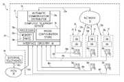
- FIG. 1is a schematic view of a communication system.
- FIG. 2is a flowchart of one procedure that can be implemented with the system of FIG. 1 .
- FIG. 3is a logical view of a configuration profile suitable for use in the procedure of FIG. 2 .
- FIG. 4is a partial diagrammatic view of a user station of FIG. 1 with Graphical User Interface (GUI) controls to send a screen sharing request in the procedure of FIG. 2 .
- GUIGraphical User Interface
- FIG. 1is a diagrammatic view of computer system 20 of one embodiment of the present invention.
- Computer system 20includes computer network 22 .
- Computer network 22couples together a number of computers 21 over network pathways 23 .
- system 20has one or more servers, including Computer Telephony (CT) server 26 and user client workstations 30 a , 30 b , and 30 c .
- CT server 26may include hardware and/or software to define an Automated Communication Distributor (ACD) 26 a .
- computers 21are each illustrated as being a server or client, it should be understood that any of computers 21 may be arranged to include both a client and server.
- computers 21are illustrated, more or fewer may be utilized in alternative embodiments.
- CT server 26includes one or more processors or CPUs 50 a and memory 52 a that can be comprised of one or more types.
- Memory 52 aincludes a removable memory device (RMD) 54 a .
- RMDremovable memory device
- each computer 21 of system 20includes one or more processors or CPUs and one or more types of memory.
- Each processormay be comprised of one or more components configured as a single unit. Alternatively, when of a multi-component form, a processor may have one or more components located remotely relative to the others. Such components of each processor may be of the electronic variety defining digital circuitry, analog circuitry, or both.
- each processoris of a conventional, integrated circuit microprocessor arrangement, such as one or more PENTIUM III or PENTIUM 4 processors supplied by INTEL Corporation of 2200 Mission College Boulevard, Santa Clara, Calif. 95052, USA.
- Each memoryis one form of computer-readable device.
- Each memorymay include one or more types of solid-state electronic memory, magnetic memory, or optical memory, just to name a few.
- each memorymay include solid-state electronic Random Access Memory (RAM), Sequentially Accessible Memory (SAM) (such as the First-In, First-Out (FIFO) variety or the Last-In-First-Out (LIFO) variety), Programmable Read Only Memory (PROM), Electronically Programmable Read Only Memory (EPROM), or Electrically Erasable Programmable Read Only Memory (EEPROM); an optical disk memory (such as a DVD or CD ROM); a magnetically encoded hard disk, floppy disk, tape, or cartridge media; or a combination of any of these memory types.
- each memorymay be volatile, nonvolatile, or a hybrid combination of volatile and nonvolatile varieties.
- System 20further illustrates Public Switched Telephone Network (PSTN) 40 coupled to interface circuitry 46 of server 26 by pathway 42 b .
- interface circuitry 46is a computer controlled switch that is in the form of one or more telephone communication processing boards, such as those offered by INTEL Corporation under the DIALOGIC® brand, or by ACULAB.
- External telephones 44are coupled to PSTN 40 by pathway 42 a .
- Interface circuitry 46is also coupled to telephone communication devices 36 a , 36 b , and 36 c g(collectively designated as telephones 36 ) by pathways 48 a , 48 b , and 48 c .
- interface circuitry 46is shown coupled to multiple telephones 36 .
- each of telephones 36may be coupled to one or more interface circuitries and that one or more interface circuitries 46 may be located at one or more physical locations.
- Interface circuitry 46may be arranged in the form of hardware for a Private Branch Exchange (PBX), predictive dialer, Automatic Communication Distributor (ACD), a combination of these, or another switching configuration as would occur to those skilled in the art.
- Telephones 36may be in the form of a handset, headset, or other arrangement as would occur to those skilled in the art.
- Telephones 36 a , 36 b , and 36 care each associated with a different one of user workstations 30 a , 30 b , and 30 c , respectively (collectively designated as user workstations 30 ).
- User workstations 30each include a user computer 32 coupled to a display 34 .
- a user computer 32 and/or display 34may be referred to specifically as user computer 32 a , 32 b , or 32 c or display 34 a , 34 b , or 34 c as each is associated with one of user workstation 30 a , 30 b , or 30 c respectively.
- telephones 36man be SIP enabled telephones operatively coupled to a digital communication network such as the Internet utilizing IP telephony technology as is known in the art.
- user workstations 30are used to administer the settings of one or more telephones 36 .
- User computers 32may be of the same type, or a heterogeneous combination of different computing devices.
- displays 34may be of the same type, or a heterogeneous combination of different visual devices.
- each user workstation 30may also include one or more operator input devices such as a keyboard, mouse, track ball, light pen, and/or microtelecommunicator, to name just a few representative examples.
- one or more other output devicesmay be included such as loudspeaker(s) and/or a printer. It shall be appreciated that these workstations and corresponding telephones and computers may be located remotely from one another, such as in a different office, building, or geographic location depending upon the implementation of system 20 .
- Computer network 22can be in the form of a Local Area Network (LAN), Municipal Area Network (MAN), Wide Area Network (WAN), such as the Internet, a combination of these, or such other network arrangement as would occur to those skilled in the art.
- the operating logic of system 20can be embodied in signals transmitted over network 22 , in programming instructions, dedicated hardware, or a combination of these. It should be understood that more or fewer computers 21 can be coupled together by computer network 22 . It should also be recognized that computer network 22 may include one or more elements of PSTN 40 . Indeed, in an alternate embodiment, PSTN 40 and computer network 22 are provided as a common network.
- system 20operates as a communication system 24 at one or more physical locations that are remote from one another with server 26 being configured as an automatic communication distributor server host. While ACD 26 a is shown defined by server 26 , in other embodiments may only partially be defined by server 26 and/or defined with one or more other servers. Likewise, a common server (such as server 26 ) or other servers can be provided for computer network management, overflow, redundancy and the like. In one embodiment, Server 26 includes phone configuration store 56 that can be used by ACD 26 a to determine the configuration settings of telephones 36 and their respective association with computers 32 of user workstations 30 . Alternatively or additionally, phone configuration store 56 could also be located on one or more other servers.
- User workstations 30 a , 30 b , and 30 care each arranged as a communication client host. Additional telephones 36 may be connected to interface circuitry 46 and can be standalone or can correspond to an additional client host to provide more user workstations 30 (not shown). Typically communication system 20 would include many more user workstations of this type at one or more physical locations, but only a few have been illustrated in FIG. 1 to preserve clarity. Also, one or more servers 26 may be configured as a communication distributor server host at one or more physical locations.
- system 20may be arranged to provide for distribution and routing of a number of different forms of communication, such as digital/analog telephone calls, voice mails, faxes, e-mail, web chats, web call backs, and the like.
- business/customer data associated with various communicationsmay be selectively accessed with system 20 . This data may be presented to a user at each user workstation 30 by way of monitor 34 operatively coupled to the corresponding user computer 32 , such as for use in a contact center.
- procedure 100demonstrates a process for establishing a screen sharing session in conjunction with a telecommunication session.
- procedure 100is at least partially implemented in the operating logic of system 20 , particularly server 26 .
- Such logiccan be in the form of software instructions, firmware instructions, dedicated hardware, or a combination of these.
- Procedure 100begins with automatic computer telephony server 26 establishing a telephone communication session between a first party and a second party (stage 102 ).
- the telephone communication sessionis established in response to either the first party or the second party dialing the number associated with the other party, by interacting with a telephone integration software package installed on their corresponding computer 32 to effectuate the same, or by another method known to one of skill in the art and the other party answering.
- the associationsmay be static or dynamic, such as based upon assignments made during deployment, scheduling, or current user logins. In the illustrative embodiment, these associations are maintained in a configuration plan stored in phone configuration store 56 of computer telephony server 26 .
- the computer telephony server 26receives a request for screen sharing from one of the parties in conjunction with the telephone communication session (stage 104 ).
- the requestmay be received from the first party using telephone 36 a .
- the requestmay be received from the telephone 36 of either the first party or second party, such as by activation of a screen sharing key, or from the computer 32 associated with either party by the party selecting the appropriate option for screen sharing within an installed telephone integration software package.
- the requestmay also be received in conjunction with the initial telephone communication session creation or at any other time during the session.
- the requestmay take one of two forms, including a request to share a selected portion of the screen of the first party's associated computer with the computer of the second party or a request by the first party to view a portion of the second party's screen.
- the device used to send the requestwhether it is telephone 36 a or computer 32 a , is unaware of the address of computer 32 b .
- the requestis necessarily free from any indication, such as the network name or address, of the computer 32 b associated with the second party.
- a similar requestmay be sent by the second party requesting to either share his screen or receive the screen of the first party. In this situation the request is necessarily free from any indication, such as the network name or address, of the computer 32 a associated with the first party.
- the computer telephony server 26determines the identifiers of the telephones active in the associated telephone communication session (stage 106 ).
- the identifieris the telephone's extension, but in other embodiments the telephone may be identified by telephone number, IP address, extension, MAC address, username, or any other unique identifier known to one of skill in the art.
- the identifiersare determined using a listing of active calls stored in memory 52 a and a configuration plan stored in phone configuration store 56 of computer telephony server 26 which includes a number of user profiles tying a telephone to a computer. As such, in accordance with the above example, the identifiers of telephones 36 a and 36 b would be determined.
- the identifier of telephone 36 ais included in the request.
- the computer telephony serveris able to access the active call associated with telephone 36 a and quickly determine the identifier of telephone 36 b .
- the requestmay be received from the first party via computer 32 a .
- the requestmay include the identifier of the associated telephone 36 a or the identifier may be looked up from the associations stored in phone configuration store 56 of computer telephony server 26 .
- the telephone identifier stored in association with computer 32 awould be that of telephone 36 a .
- the identifier of the other telephone to the sessionis identified from the active call associated with telephone 36 a and determined to be the identifier of telephone 36 b.
- Configuration plan 150is preferably stored electronically in the phone configuration store 56 of computer telephony server 26 .
- Configuration plan 150includes a plurality of rows each representing an association. Each row may include an entry in the telephone identifier column 152 , user ID column 154 , computer address column 156 , configuration options 158 , and current status 160 .
- the first partyis using telephone 36 a which is identified by telephone identifier “6895” in column 152 .
- it can easily be determined that the corresponding computer 32 a for the first useris identified by the network address “192.168.5.62”.
- the second partyis using telephone 36 b which is identified by telephone identifier “7248” in column 152 .
- computer 32 b associated with the second useris identified by the network address “192.168.6.78”.
- the configuration options in column 158identify that the first party denies permission to all screen sharing requests and that the second party allows all screen sharing requests without prompting, such as might be the case for a contact center worker. Additionally, by viewing the current status column 160 associated with each column, the current call status of a telephone can be obtained.
- the computer telephony server 26may utilize the configuration plan 150 to cross reference the status of the telephone device or computer requesting the screen sharing session to locate the address of the computer associated with the other party to the telecommunication session with which the request is associated.
- the computer telephony server 26utilizes them to look up the computers which correspond to the identified telephones. Using the configuration plan of phone configuration store 56 , as described with respect to FIG. 3 , the computer telephony server utilizes the telephone identifiers to determine the corresponding identifiers of the computers associated with the telephones.
- the computer identifiersare network addresses, but in alternate forms, the identifiers may be network names or other unique identifiers known to one of skill in the art. In the alternate form described herein, where the request is received from the computer 32 a for the first user, then the only computer identifier to be determined may be that of computer 32 b associated with the second party.
- the screen sharing sessionmay be established (stage 110 ).
- the screen sharing sessionis preferably established over a data channel, such as network 22 or the like.
- the data channelmay also include portions of the Internet or other data networks.
- the screen sharing sessionis established as a Realtime Transport Protocol (RTP) session over the User Datagram Protocol (UDP).
- RTPRealtime Transport Protocol
- UDPUser Datagram Protocol
- the screen data within the screen sharing sessionis presented to the receiving user workstations in near real-time, which shall be construed to mean that the data is transmitted from the sending computer to the receiving computer in a time without substantial delay, which may naturally include any transmission delay or lag that is commonly acceptable in applications of this type due to bandwidth or latency issues.
- the screen sharing sessionis encrypted to prevent unauthorized access to the screen information being transported.
- the screen sharing requestmay be either a request to share or a request to receive a shared screen from either user.
- the process for establishing the screen sharing session in response to each requestmay be customized with user permission requests or default settings in order to require a user's permission prior to sharing his associated screen with a requesting party.
- the processmonitors for the termination of the associated telecommunication session at process block 112 . If the telecommunication session remains active, the process determines if a screen sharing session termination request has been received (stage 114 ). If no request is received, the process returns to monitor for termination of the telecommunication session. If the process determines that the associated telecommunication session has been terminated then the process closes the screen sharing session (stage 116 ) and the process ends at end point 118 . Similarly, if the process receives a screen sharing termination request, then the process closes the screen sharing session (stage 116 ) and the process ends at end point 118 . It shall be appreciated that in the illustrated embodiment, the screen sharing session is terminated upon the termination of the telephone communication session. However, in alternate forms, the screen sharing session may be allowed to persist depending upon configuration preferences.
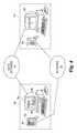
- FIG. 4is a partial diagrammatic view of the user station 30 a and 30 b of FIG. 1 with Graphical User Interface (GUI) controls and telephone controls to establish a screen sharing session using the procedure of FIG. 2 .
- GUIGraphical User Interface
- Screen 34 aincludes a computer telephony integration application 180 running on computer 32 a .
- the first party, associated with workstation 30 amay initiate a screen sharing request by activating screen sharing button 182 of application 180 or by activating screen sharing button 190 of telephone 36 a .
- the screen “Screen 2” from monitor 34 bwill be transmitted via data network 196 to the monitor 34 a for display in a window or selectively in full screen.
- screen sharing sessionsmay be hosted or established by server 26 to facilitate the transmission of screen data from one or more computers to a plurality of computers associated with telephones connected to the conference.
- multiple screensmay be simultaneously shared or selected from by a conference host.
- screen sharing sessionsare preferably tied to a respective telecommunication session and closed upon their termination.
- a screen sharing session between two partiesis terminated when either party to the communication hangs up.
- a disconnection or other inadvertent hang upmaybe detected, allowing the screen sharing session to persist for a short period of time in which the two parties may reconnect.
- a screen sharing sessionmay be configured to persist after termination of a telecommunication session, but this is not typically the default.
- the communication sessioncan be based on standard Public Switched Telephone Network (PSTN) telephone lines, wireless telephone, and/or a publicly accessible computer network, such as the internet, to provide voice or another aurally-perceived form of communication, to name just a few examples.
- PSTNPublic Switched Telephone Network
- wireless telephonewireless telephone
- a publicly accessible computer networksuch as the internet
Landscapes
- Engineering & Computer Science (AREA)
- General Engineering & Computer Science (AREA)
- Signal Processing (AREA)
- Telephonic Communication Services (AREA)
Abstract
Description
Claims (26)
Priority Applications (1)
| Application Number | Priority Date | Filing Date | Title |
|---|---|---|---|
| US12/026,947US8199891B2 (en) | 2008-02-06 | 2008-02-06 | System and method for remote screen monitoring |
Applications Claiming Priority (1)
| Application Number | Priority Date | Filing Date | Title |
|---|---|---|---|
| US12/026,947US8199891B2 (en) | 2008-02-06 | 2008-02-06 | System and method for remote screen monitoring |
Publications (2)
| Publication Number | Publication Date |
|---|---|
| US20090196406A1 US20090196406A1 (en) | 2009-08-06 |
| US8199891B2true US8199891B2 (en) | 2012-06-12 |
Family
ID=40931694
Family Applications (1)
| Application Number | Title | Priority Date | Filing Date |
|---|---|---|---|
| US12/026,947Active2031-03-18US8199891B2 (en) | 2008-02-06 | 2008-02-06 | System and method for remote screen monitoring |
Country Status (1)
| Country | Link |
|---|---|
| US (1) | US8199891B2 (en) |
Cited By (13)
| Publication number | Priority date | Publication date | Assignee | Title |
|---|---|---|---|---|
| US20080222240A1 (en)* | 1998-09-11 | 2008-09-11 | Genesys Telecommunications Laboratories, Inc. | Method and Apparatus for Extended Management of State and Interaction of a Remote Knowledge Worker from a Contact Center |
| US20130141517A1 (en)* | 2011-12-06 | 2013-06-06 | Aastra Technologies Limited | Collaboration system & method |
| US8971216B2 (en) | 1998-09-11 | 2015-03-03 | Alcatel Lucent | Method for routing transactions between internal and external partners in a communication center |
| US9008075B2 (en) | 2005-12-22 | 2015-04-14 | Genesys Telecommunications Laboratories, Inc. | System and methods for improving interaction routing performance |
| USRE45583E1 (en) | 1999-12-01 | 2015-06-23 | Genesys Telecommunications Laboratories, Inc. | Method and apparatus for providing enhanced communication capability for mobile devices on a virtual private network |
| USRE45606E1 (en) | 1997-02-10 | 2015-07-07 | Genesys Telecommunications Laboratories, Inc. | Call and data correspondence in a call-in center employing virtual restructuring for computer telephony integrated functionality |
| USRE46060E1 (en) | 1997-02-10 | 2016-07-05 | Genesys Telecommunications Laboratories, Inc. | In-band signaling for routing |
| USRE46153E1 (en) | 1998-09-11 | 2016-09-20 | Genesys Telecommunications Laboratories, Inc. | Method and apparatus enabling voice-based management of state and interaction of a remote knowledge worker in a contact center environment |
| US9516171B2 (en) | 1997-02-10 | 2016-12-06 | Genesys Telecommunications Laboratories, Inc. | Personal desktop router |
| US9553755B2 (en) | 1998-02-17 | 2017-01-24 | Genesys Telecommunications Laboratories, Inc. | Method for implementing and executing communication center routing strategies represented in extensible markup language |
| USRE46438E1 (en) | 1999-09-24 | 2017-06-13 | Genesys Telecommunications Laboratories, Inc. | Method and apparatus for data-linking a mobile knowledge worker to home communication-center infrastructure |
| USRE46528E1 (en) | 1997-11-14 | 2017-08-29 | Genesys Telecommunications Laboratories, Inc. | Implementation of call-center outbound dialing capability at a telephony network level |
| US10956015B1 (en) | 2019-09-11 | 2021-03-23 | International Business Machines Corporation | User notification based on visual trigger event |
Families Citing this family (13)
| Publication number | Priority date | Publication date | Assignee | Title |
|---|---|---|---|---|
| US8300783B2 (en)* | 2009-02-09 | 2012-10-30 | Applied Minds, Llc | Method and apparatus for establishing data link based on audio connection |
| US8542807B2 (en)* | 2009-02-09 | 2013-09-24 | Applied Minds, Llc | Method and apparatus for establishing a data link based on a pots connection |
| CN102457544B (en)* | 2010-10-26 | 2014-12-03 | 深圳市誉融科技有限公司 | Method and system for acquiring screen image in screen sharing system based on Internet |
| US9600350B2 (en) | 2011-06-16 | 2017-03-21 | Vmware, Inc. | Delivery of a user interface using hypertext transfer protocol |
| US9514242B2 (en) | 2011-08-29 | 2016-12-06 | Vmware, Inc. | Presenting dynamically changing images in a limited rendering environment |
| US9549045B2 (en)* | 2011-08-29 | 2017-01-17 | Vmware, Inc. | Sharing remote sessions of a user interface and/or graphics of a computer |
| WO2013069214A1 (en)* | 2011-11-08 | 2013-05-16 | 日本電気株式会社 | Content display terminal selection system |
| US20130179507A1 (en)* | 2012-01-06 | 2013-07-11 | Microsoft Corporation | Communicating Media Data |
| JP6381187B2 (en)* | 2013-08-09 | 2018-08-29 | キヤノン株式会社 | Information processing apparatus, information processing method, and program |
| EP3133870B1 (en)* | 2014-05-06 | 2019-09-18 | Huawei Technologies Co., Ltd. | Apparatus and method for realizing collaborative work of cells |
| JP2017049851A (en)* | 2015-09-02 | 2017-03-09 | 株式会社リコー | Information processing system, information processing apparatus and program |
| US9832314B2 (en)* | 2015-12-08 | 2017-11-28 | Verizon Patent And Licensing Inc. | Customer representative remote access for troubleshooting smartphones |
| CN116405631A (en)* | 2020-07-08 | 2023-07-07 | 华为技术有限公司 | Screen sharing method, terminal and storage medium |
Citations (19)
| Publication number | Priority date | Publication date | Assignee | Title |
|---|---|---|---|---|
| US5704042A (en) | 1993-03-19 | 1997-12-30 | Ncr Corporation | Accelerated replication of multiple computer displays |
| US5995096A (en) | 1991-10-23 | 1999-11-30 | Hitachi, Ltd. | Conference display control method and apparatus for an electronic conference for displaying either shared or local data and transferring local data |
| US6204847B1 (en) | 1995-07-17 | 2001-03-20 | Daniel W. Wright | Shared virtual desktop collaborative application system |
| US6209021B1 (en) | 1993-04-13 | 2001-03-27 | Intel Corporation | System for computer supported collaboration |
| US6560637B1 (en) | 1998-12-02 | 2003-05-06 | Polycom, Inc. | Web-enabled presentation device and methods of use thereof |
| US6608636B1 (en) | 1992-05-13 | 2003-08-19 | Ncr Corporation | Server based virtual conferencing |
| US20040008837A1 (en)* | 2002-07-12 | 2004-01-15 | Nortel Networks Limited | Combining multimedia services with traditional telephony services in a public branch exchange |
| US6690654B2 (en) | 1996-11-18 | 2004-02-10 | Mci Communications Corporation | Method and system for multi-media collaboration between remote parties |
| US6741586B1 (en) | 2000-05-31 | 2004-05-25 | 3Com Corporation | System and method for sharing computer screens over a telephony network |
| US6750897B1 (en)* | 2001-08-16 | 2004-06-15 | Verizon Data Services Inc. | Systems and methods for implementing internet video conferencing using standard phone calls |
| US20050008000A1 (en)* | 2003-07-08 | 2005-01-13 | Jacek Korycki | Enhanced phone-based collaboration |
| US6907449B2 (en) | 1998-09-22 | 2005-06-14 | Qwest Communications International, Inc. | Conferencing system for simultaneous broadcast of audio and transmission of documents via push technology |
| US20050286699A1 (en) | 2004-06-22 | 2005-12-29 | Gagle Michael D | System and method for automatic conferencing |
| US20060080432A1 (en) | 2004-09-03 | 2006-04-13 | Spataro Jared M | Systems and methods for collaboration |
| US7283154B2 (en)* | 2001-12-31 | 2007-10-16 | Emblaze V Con Ltd | Systems and methods for videoconference and/or data collaboration initiation |
| US20070263830A1 (en)* | 2006-04-11 | 2007-11-15 | Alcatel | System and method for transitioning a voice session in progress over a communication network into a voice and data session |
| US7453815B1 (en)* | 1999-02-19 | 2008-11-18 | 3Com Corporation | Method and system for monitoring and management of the performance of real-time networks |
| US20090164640A1 (en)* | 2007-12-20 | 2009-06-25 | Verizon Business Network Services Inc. | Multimedia personal assistant |
| US20090323552A1 (en)* | 2007-10-01 | 2009-12-31 | Hewlett-Packard Development Company, L.P. | Systems and Methods for Managing Virtual Collaboration Systems Spread Over Different Networks |
Family Cites Families (2)
| Publication number | Priority date | Publication date | Assignee | Title |
|---|---|---|---|---|
| US5956026A (en)* | 1997-12-19 | 1999-09-21 | Sharp Laboratories Of America, Inc. | Method for hierarchical summarization and browsing of digital video |
| US6608633B1 (en)* | 1998-10-30 | 2003-08-19 | Sony Corporation | Visual display of categorical information through visual factors such as scale and location |
- 2008
- 2008-02-06USUS12/026,947patent/US8199891B2/enactiveActive
Patent Citations (19)
| Publication number | Priority date | Publication date | Assignee | Title |
|---|---|---|---|---|
| US5995096A (en) | 1991-10-23 | 1999-11-30 | Hitachi, Ltd. | Conference display control method and apparatus for an electronic conference for displaying either shared or local data and transferring local data |
| US6608636B1 (en) | 1992-05-13 | 2003-08-19 | Ncr Corporation | Server based virtual conferencing |
| US5704042A (en) | 1993-03-19 | 1997-12-30 | Ncr Corporation | Accelerated replication of multiple computer displays |
| US6209021B1 (en) | 1993-04-13 | 2001-03-27 | Intel Corporation | System for computer supported collaboration |
| US6204847B1 (en) | 1995-07-17 | 2001-03-20 | Daniel W. Wright | Shared virtual desktop collaborative application system |
| US6690654B2 (en) | 1996-11-18 | 2004-02-10 | Mci Communications Corporation | Method and system for multi-media collaboration between remote parties |
| US6907449B2 (en) | 1998-09-22 | 2005-06-14 | Qwest Communications International, Inc. | Conferencing system for simultaneous broadcast of audio and transmission of documents via push technology |
| US6560637B1 (en) | 1998-12-02 | 2003-05-06 | Polycom, Inc. | Web-enabled presentation device and methods of use thereof |
| US7453815B1 (en)* | 1999-02-19 | 2008-11-18 | 3Com Corporation | Method and system for monitoring and management of the performance of real-time networks |
| US6741586B1 (en) | 2000-05-31 | 2004-05-25 | 3Com Corporation | System and method for sharing computer screens over a telephony network |
| US6750897B1 (en)* | 2001-08-16 | 2004-06-15 | Verizon Data Services Inc. | Systems and methods for implementing internet video conferencing using standard phone calls |
| US7283154B2 (en)* | 2001-12-31 | 2007-10-16 | Emblaze V Con Ltd | Systems and methods for videoconference and/or data collaboration initiation |
| US20040008837A1 (en)* | 2002-07-12 | 2004-01-15 | Nortel Networks Limited | Combining multimedia services with traditional telephony services in a public branch exchange |
| US20050008000A1 (en)* | 2003-07-08 | 2005-01-13 | Jacek Korycki | Enhanced phone-based collaboration |
| US20050286699A1 (en) | 2004-06-22 | 2005-12-29 | Gagle Michael D | System and method for automatic conferencing |
| US20060080432A1 (en) | 2004-09-03 | 2006-04-13 | Spataro Jared M | Systems and methods for collaboration |
| US20070263830A1 (en)* | 2006-04-11 | 2007-11-15 | Alcatel | System and method for transitioning a voice session in progress over a communication network into a voice and data session |
| US20090323552A1 (en)* | 2007-10-01 | 2009-12-31 | Hewlett-Packard Development Company, L.P. | Systems and Methods for Managing Virtual Collaboration Systems Spread Over Different Networks |
| US20090164640A1 (en)* | 2007-12-20 | 2009-06-25 | Verizon Business Network Services Inc. | Multimedia personal assistant |
Non-Patent Citations (1)
| Title |
|---|
| Microsoft Corporation, Choosing a Microsoft Web Conferencing Solution, Published: Aug. 2007. |
Cited By (23)
| Publication number | Priority date | Publication date | Assignee | Title |
|---|---|---|---|---|
| USRE45606E1 (en) | 1997-02-10 | 2015-07-07 | Genesys Telecommunications Laboratories, Inc. | Call and data correspondence in a call-in center employing virtual restructuring for computer telephony integrated functionality |
| USRE46243E1 (en) | 1997-02-10 | 2016-12-20 | Genesys Telecommunications Laboratories, Inc. | In-band signaling for routing |
| US9516171B2 (en) | 1997-02-10 | 2016-12-06 | Genesys Telecommunications Laboratories, Inc. | Personal desktop router |
| USRE46060E1 (en) | 1997-02-10 | 2016-07-05 | Genesys Telecommunications Laboratories, Inc. | In-band signaling for routing |
| USRE46521E1 (en) | 1997-09-30 | 2017-08-22 | Genesys Telecommunications Laboratories, Inc. | Method and apparatus for extended management of state and interaction of a remote knowledge worker from a contact center |
| USRE46528E1 (en) | 1997-11-14 | 2017-08-29 | Genesys Telecommunications Laboratories, Inc. | Implementation of call-center outbound dialing capability at a telephony network level |
| US9553755B2 (en) | 1998-02-17 | 2017-01-24 | Genesys Telecommunications Laboratories, Inc. | Method for implementing and executing communication center routing strategies represented in extensible markup language |
| US9002920B2 (en) | 1998-09-11 | 2015-04-07 | Genesys Telecommunications Laboratories, Inc. | Method and apparatus for extended management of state and interaction of a remote knowledge worker from a contact center |
| US9350808B2 (en) | 1998-09-11 | 2016-05-24 | Alcatel Lucent | Method for routing transactions between internal and external partners in a communication center |
| US20080222240A1 (en)* | 1998-09-11 | 2008-09-11 | Genesys Telecommunications Laboratories, Inc. | Method and Apparatus for Extended Management of State and Interaction of a Remote Knowledge Worker from a Contact Center |
| USRE46153E1 (en) | 1998-09-11 | 2016-09-20 | Genesys Telecommunications Laboratories, Inc. | Method and apparatus enabling voice-based management of state and interaction of a remote knowledge worker in a contact center environment |
| USRE46387E1 (en) | 1998-09-11 | 2017-05-02 | Genesys Telecommunications Laboratories, Inc. | Method and apparatus for extended management of state and interaction of a remote knowledge worker from a contact center |
| US8971216B2 (en) | 1998-09-11 | 2015-03-03 | Alcatel Lucent | Method for routing transactions between internal and external partners in a communication center |
| US10218848B2 (en) | 1998-09-11 | 2019-02-26 | Genesys Telecommunications Laboratories, Inc. | Method and apparatus for extended management of state and interaction of a remote knowledge worker from a contact center |
| USRE46438E1 (en) | 1999-09-24 | 2017-06-13 | Genesys Telecommunications Laboratories, Inc. | Method and apparatus for data-linking a mobile knowledge worker to home communication-center infrastructure |
| USRE46457E1 (en) | 1999-09-24 | 2017-06-27 | Genesys Telecommunications Laboratories, Inc. | Method and apparatus for data-linking a mobile knowledge worker to home communication-center infrastructure |
| USRE45583E1 (en) | 1999-12-01 | 2015-06-23 | Genesys Telecommunications Laboratories, Inc. | Method and apparatus for providing enhanced communication capability for mobile devices on a virtual private network |
| USRE46538E1 (en) | 2002-10-10 | 2017-09-05 | Genesys Telecommunications Laboratories, Inc. | Method and apparatus for extended management of state and interaction of a remote knowledge worker from a contact center |
| US9008075B2 (en) | 2005-12-22 | 2015-04-14 | Genesys Telecommunications Laboratories, Inc. | System and methods for improving interaction routing performance |
| US9854006B2 (en) | 2005-12-22 | 2017-12-26 | Genesys Telecommunications Laboratories, Inc. | System and methods for improving interaction routing performance |
| US9035991B2 (en)* | 2011-12-06 | 2015-05-19 | Mitel Networks Corporation | Collaboration system and method |
| US20130141517A1 (en)* | 2011-12-06 | 2013-06-06 | Aastra Technologies Limited | Collaboration system & method |
| US10956015B1 (en) | 2019-09-11 | 2021-03-23 | International Business Machines Corporation | User notification based on visual trigger event |
Also Published As
| Publication number | Publication date |
|---|---|
| US20090196406A1 (en) | 2009-08-06 |
Similar Documents
| Publication | Publication Date | Title |
|---|---|---|
| US8199891B2 (en) | System and method for remote screen monitoring | |
| US8442208B2 (en) | Method and system for transferring an automatic call distributor call | |
| US12218773B2 (en) | Video conference acceleration | |
| US8565384B2 (en) | Systems, methods, and media for connecting emergency communications | |
| CA2591732C (en) | Intelligent audio limit method, system and node | |
| RU2396730C2 (en) | Control of conference layout and control protocol | |
| US20070291667A1 (en) | Intelligent audio limit method, system and node | |
| US20070067387A1 (en) | Conferencing system and method for temporary blocking / restoring of individual participants | |
| US20120086769A1 (en) | Conference layout control and control protocol | |
| US20030158900A1 (en) | Method of and apparatus for teleconferencing | |
| US20070294263A1 (en) | Associating independent multimedia sources into a conference call | |
| EP1868347A2 (en) | Associating independent multimedia sources into a conference call | |
| US9154317B2 (en) | Method and apparatus for providing bridgeless conferencing services | |
| US10425451B2 (en) | Handling call waiting, multiple calls, and hold/resume using web real-time communications technology | |
| US10623350B2 (en) | Subscription/notification of a conference in a collaboration conferencing system | |
| CA2965345A1 (en) | Conferencing intelligence engine in a collaboration conferencing system | |
| US10187529B2 (en) | Systems and methods for conducting conference calls | |
| CA2965337A1 (en) | Identification token in a collaboration conferencing system | |
| WO2007027523A2 (en) | Video relay system and method | |
| US9160549B2 (en) | Method and apparatus for providing bridgeless conferencing services | |
| Rosas et al. | Videoconference system based on WebRTC with access to the PSTN | |
| US20140327728A1 (en) | Method and system for mapping virtual conference rooms between 2 independent systems | |
| EP2583431B1 (en) | Procedure for commercial communications | |
| US10637992B2 (en) | Method and apparatus for group calling in an IP-based communication system | |
| US20050286699A1 (en) | System and method for automatic conferencing |
Legal Events
| Date | Code | Title | Description |
|---|---|---|---|
| AS | Assignment | Owner name:INTERACTIVE INTELLIGENCE, INC., INDIANA Free format text:ASSIGNMENT OF ASSIGNORS INTEREST;ASSIGNORS:BROWN, DONALD E.;GAGLE, MICHAEL D.;REEL/FRAME:020473/0361 Effective date:20080124 | |
| STCF | Information on status: patent grant | Free format text:PATENTED CASE | |
| CC | Certificate of correction | ||
| FPAY | Fee payment | Year of fee payment:4 | |
| AS | Assignment | Owner name:INTERACTIVE INTELLIGENCE GROUP, INC., INDIANA Free format text:ASSIGNMENT OF ASSIGNORS INTEREST;ASSIGNOR:INTERACTIVE INTELLIGENCE, INC.;REEL/FRAME:040647/0285 Effective date:20161013 | |
| AS | Assignment | Owner name:BANK OF AMERICA, N.A., AS COLLATERAL AGENT, NORTH CAROLINA Free format text:SECURITY AGREEMENT;ASSIGNORS:GENESYS TELECOMMUNICATIONS LABORATORIES, INC., AS GRANTOR;ECHOPASS CORPORATION;INTERACTIVE INTELLIGENCE GROUP, INC.;AND OTHERS;REEL/FRAME:040815/0001 Effective date:20161201 Owner name:BANK OF AMERICA, N.A., AS COLLATERAL AGENT, NORTH Free format text:SECURITY AGREEMENT;ASSIGNORS:GENESYS TELECOMMUNICATIONS LABORATORIES, INC., AS GRANTOR;ECHOPASS CORPORATION;INTERACTIVE INTELLIGENCE GROUP, INC.;AND OTHERS;REEL/FRAME:040815/0001 Effective date:20161201 | |
| AS | Assignment | Owner name:GENESYS TELECOMMUNICATIONS LABORATORIES, INC., CALIFORNIA Free format text:MERGER;ASSIGNOR:INTERACTIVE INTELLIGENCE GROUP, INC.;REEL/FRAME:046463/0839 Effective date:20170701 Owner name:GENESYS TELECOMMUNICATIONS LABORATORIES, INC., CAL Free format text:MERGER;ASSIGNOR:INTERACTIVE INTELLIGENCE GROUP, INC.;REEL/FRAME:046463/0839 Effective date:20170701 | |
| MAFP | Maintenance fee payment | Free format text:PAYMENT OF MAINTENANCE FEE, 8TH YEAR, LARGE ENTITY (ORIGINAL EVENT CODE: M1552); ENTITY STATUS OF PATENT OWNER: LARGE ENTITY Year of fee payment:8 | |
| MAFP | Maintenance fee payment | Free format text:PAYMENT OF MAINTENANCE FEE, 12TH YEAR, LARGE ENTITY (ORIGINAL EVENT CODE: M1553); ENTITY STATUS OF PATENT OWNER: LARGE ENTITY Year of fee payment:12 | |
| AS | Assignment | Owner name:GENESYS CLOUD SERVICES, INC., CALIFORNIA Free format text:CHANGE OF NAME;ASSIGNOR:GENESYS TELECOMMUNICATIONS LABORATORIES, INC.;REEL/FRAME:067651/0783 Effective date:20210315 | |
| AS | Assignment | Owner name:GOLDMAN SACHS BANK USA, AS SUCCESSOR AGENT, TEXAS Free format text:NOTICE OF SUCCESSION OF SECURITY INTERESTS AT REEL/FRAME 040815/0001;ASSIGNOR:BANK OF AMERICA, N.A., AS RESIGNING AGENT;REEL/FRAME:070498/0001 Effective date:20250130 |