US8199725B2 - Rank indicator transmission during discontinuous reception - Google Patents
Rank indicator transmission during discontinuous receptionDownload PDFInfo
- Publication number
- US8199725B2 US8199725B2US12/058,444US5844408AUS8199725B2US 8199725 B2US8199725 B2US 8199725B2US 5844408 AUS5844408 AUS 5844408AUS 8199725 B2US8199725 B2US 8199725B2
- Authority
- US
- United States
- Prior art keywords
- duration
- periodic
- reporting
- time period
- processor
- Prior art date
- Legal status (The legal status is an assumption and is not a legal conclusion. Google has not performed a legal analysis and makes no representation as to the accuracy of the status listed.)
- Active, expires
Links
- 230000005540biological transmissionEffects0.000titledescription30
- 230000000737periodic effectEffects0.000claimsabstractdescription64
- 238000000034methodMethods0.000claimsdescription52
- 239000011159matrix materialSubstances0.000claimsdescription2
- 238000012545processingMethods0.000description34
- 238000004891communicationMethods0.000description30
- 230000008569processEffects0.000description15
- 230000008054signal transmissionEffects0.000description14
- 230000006870functionEffects0.000description13
- 230000015654memoryEffects0.000description11
- 238000010586diagramMethods0.000description6
- 238000005516engineering processMethods0.000description6
- 230000004044responseEffects0.000description6
- 230000001131transforming effectEffects0.000description6
- 125000004122cyclic groupChemical group0.000description4
- 230000007246mechanismEffects0.000description3
- 230000007480spreadingEffects0.000description3
- 230000008901benefitEffects0.000description2
- 238000006243chemical reactionMethods0.000description2
- 238000013500data storageMethods0.000description2
- 230000000994depressogenic effectEffects0.000description2
- 238000012905input functionMethods0.000description2
- 239000004973liquid crystal related substanceSubstances0.000description2
- 238000007726management methodMethods0.000description2
- 238000005259measurementMethods0.000description2
- 230000003287optical effectEffects0.000description2
- 230000002093peripheral effectEffects0.000description2
- 230000011664signalingEffects0.000description2
- 238000012546transferMethods0.000description2
- 101000741965Homo sapiens Inactive tyrosine-protein kinase PRAG1Proteins0.000description1
- 102100038659Inactive tyrosine-protein kinase PRAG1Human genes0.000description1
- 241000699670Mus sp.Species0.000description1
- 230000006978adaptationEffects0.000description1
- 230000004075alterationEffects0.000description1
- 230000006399behaviorEffects0.000description1
- 238000004422calculation algorithmMethods0.000description1
- 230000001413cellular effectEffects0.000description1
- 238000004590computer programMethods0.000description1
- 239000004020conductorSubstances0.000description1
- 238000013479data entryMethods0.000description1
- 230000003247decreasing effectEffects0.000description1
- 230000000694effectsEffects0.000description1
- 239000000835fiberSubstances0.000description1
- 230000003993interactionEffects0.000description1
- 230000007774longtermEffects0.000description1
- 238000010295mobile communicationMethods0.000description1
- 239000013307optical fiberSubstances0.000description1
- 238000013515scriptMethods0.000description1
- 238000006467substitution reactionMethods0.000description1
- 230000001960triggered effectEffects0.000description1
- 230000002618waking effectEffects0.000description1
Images


Classifications
- H—ELECTRICITY
- H04—ELECTRIC COMMUNICATION TECHNIQUE
- H04W—WIRELESS COMMUNICATION NETWORKS
- H04W72/00—Local resource management
- H04W72/50—Allocation or scheduling criteria for wireless resources
- H04W72/56—Allocation or scheduling criteria for wireless resources based on priority criteria
- H04W72/563—Allocation or scheduling criteria for wireless resources based on priority criteria of the wireless resources
- H—ELECTRICITY
- H04—ELECTRIC COMMUNICATION TECHNIQUE
- H04L—TRANSMISSION OF DIGITAL INFORMATION, e.g. TELEGRAPHIC COMMUNICATION
- H04L1/00—Arrangements for detecting or preventing errors in the information received
- H04L1/0001—Systems modifying transmission characteristics according to link quality, e.g. power backoff
- H04L1/0023—Systems modifying transmission characteristics according to link quality, e.g. power backoff characterised by the signalling
- H04L1/0027—Scheduling of signalling, e.g. occurrence thereof
- H—ELECTRICITY
- H04—ELECTRIC COMMUNICATION TECHNIQUE
- H04W—WIRELESS COMMUNICATION NETWORKS
- H04W72/00—Local resource management
- H04W72/20—Control channels or signalling for resource management
- H—ELECTRICITY
- H04—ELECTRIC COMMUNICATION TECHNIQUE
- H04W—WIRELESS COMMUNICATION NETWORKS
- H04W72/00—Local resource management
- H04W72/20—Control channels or signalling for resource management
- H04W72/23—Control channels or signalling for resource management in the downlink direction of a wireless link, i.e. towards a terminal
- H—ELECTRICITY
- H04—ELECTRIC COMMUNICATION TECHNIQUE
- H04W—WIRELESS COMMUNICATION NETWORKS
- H04W76/00—Connection management
- H04W76/20—Manipulation of established connections
- H04W76/28—Discontinuous transmission [DTX]; Discontinuous reception [DRX]
- H—ELECTRICITY
- H04—ELECTRIC COMMUNICATION TECHNIQUE
- H04W—WIRELESS COMMUNICATION NETWORKS
- H04W8/00—Network data management
- H04W8/22—Processing or transfer of terminal data, e.g. status or physical capabilities
- H04W8/24—Transfer of terminal data
- H—ELECTRICITY
- H04—ELECTRIC COMMUNICATION TECHNIQUE
- H04L—TRANSMISSION OF DIGITAL INFORMATION, e.g. TELEGRAPHIC COMMUNICATION
- H04L1/00—Arrangements for detecting or preventing errors in the information received
- H04L1/12—Arrangements for detecting or preventing errors in the information received by using return channel
- H04L1/16—Arrangements for detecting or preventing errors in the information received by using return channel in which the return channel carries supervisory signals, e.g. repetition request signals
- H04L1/18—Automatic repetition systems, e.g. Van Duuren systems
- H04L1/1867—Arrangements specially adapted for the transmitter end
- H04L1/1887—Scheduling and prioritising arrangements
- H—ELECTRICITY
- H04—ELECTRIC COMMUNICATION TECHNIQUE
- H04L—TRANSMISSION OF DIGITAL INFORMATION, e.g. TELEGRAPHIC COMMUNICATION
- H04L5/00—Arrangements affording multiple use of the transmission path
- H04L5/003—Arrangements for allocating sub-channels of the transmission path
- H04L5/0053—Allocation of signalling, i.e. of overhead other than pilot signals
- H—ELECTRICITY
- H04—ELECTRIC COMMUNICATION TECHNIQUE
- H04W—WIRELESS COMMUNICATION NETWORKS
- H04W24/00—Supervisory, monitoring or testing arrangements
- H04W24/04—Arrangements for maintaining operational condition
- H—ELECTRICITY
- H04—ELECTRIC COMMUNICATION TECHNIQUE
- H04W—WIRELESS COMMUNICATION NETWORKS
- H04W28/00—Network traffic management; Network resource management
- H04W28/02—Traffic management, e.g. flow control or congestion control
- H04W28/04—Error control
- Y—GENERAL TAGGING OF NEW TECHNOLOGICAL DEVELOPMENTS; GENERAL TAGGING OF CROSS-SECTIONAL TECHNOLOGIES SPANNING OVER SEVERAL SECTIONS OF THE IPC; TECHNICAL SUBJECTS COVERED BY FORMER USPC CROSS-REFERENCE ART COLLECTIONS [XRACs] AND DIGESTS
- Y02—TECHNOLOGIES OR APPLICATIONS FOR MITIGATION OR ADAPTATION AGAINST CLIMATE CHANGE
- Y02D—CLIMATE CHANGE MITIGATION TECHNOLOGIES IN INFORMATION AND COMMUNICATION TECHNOLOGIES [ICT], I.E. INFORMATION AND COMMUNICATION TECHNOLOGIES AIMING AT THE REDUCTION OF THEIR OWN ENERGY USE
- Y02D30/00—Reducing energy consumption in communication networks
- Y02D30/70—Reducing energy consumption in communication networks in wireless communication networks
Definitions
- UEuser equipment
- user equipmentmay refer to a device and its associated Universal Integrated Circuit Card (UICC) that includes a Subscriber Identity Module (SIM) application, a Universal Subscriber Identity Module (USIM) application, or a Removable User identity Module (R-UIM) application or may refer to the device itself without such a card.
- SIMSubscriber Identity Module
- USIMUniversal Subscriber Identity Module
- R-UIMRemovable User identity Module
- a UEmight communicate with a second UE, some other element in a telecommunications network, an automated computing device such as a server computer, or some other device.
- a communications connection between a UE and another componentmight promote a voice call, a file transfer, or some other type of data exchange, any of which can be referred to as a call or a session.
- This advanced network access equipmentmight include, for example, an enhanced node B (ENB) rather than a base station or other systems and devices that are more highly evolved than the equivalent equipment in a traditional wireless telecommunications system.
- ENBenhanced node B
- Such advanced or next generation equipmentmay be referred to herein as long-term evolution (LTE) equipment.
- LTElong-term evolution
- ENBaccess nodes
- VoIPVoice over Internet Protocol
- VoIPVoice over Internet Protocol
- the signal that carries data between a UE and an ENBcan have a specific set of frequency, code, and time parameters and other characteristics that might be specified by the ENB.
- a connection between a UE and an ENB that has a specific set of such characteristicscan be referred to as a resource.
- An ENBtypically establishes a different resource for each UE with which it is communicating at any particular time.
- New wireless communications systemsmay employ multiple input multiple output (MIMO) communication techniques.
- MIMOinvolves one or both of the UE and the ENB concurrently using multiple antennas for transmitting and/or receiving.
- the multiple antennasmay be employed to increase the throughput of the radio link between the UE and the ENB, for example by transmitting independent streams of data on each antenna, or to increase the reliability of the radio link between the UE and the ENB, for example by transmitting redundant streams of data on the multiple antennas.
- These different communications objectivesmay be obtained through spatial multiplexing in the first case and through spatial diversity in the second case.
- Receiving multiple concurrent transmissions from a multi-antenna transmitter by a multi-antenna receivermay involve complicated processing techniques and or algorithms.
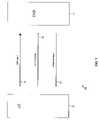
- FIG. 1is a block diagram of a telecommunications system according to an embodiment of the disclosure.
- FIG. 2is a diagram illustrating on-durations and off-durations for a user equipment according to an embodiment of the disclosure.
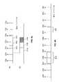
- FIG. 3 ais an illustration of a periodic rank indicator (RI) reporting resource relative to an on-duration and a retransmission window associated with the on-duration according to an embodiment of the disclosure.
- RIperiodic rank indicator
- FIG. 3 bis an illustration of a periodic rank indicator reporting resource relative to an on-duration and a retransmission window associated with the on-duration, depicting some rank indicator transmissions turned off according to an embodiment of the disclosure.
- FIG. 3 cis an illustration of a periodic rank indicator reporting resource relative to an on-duration and a retransmission window associated with the on-duration, depicting some rank indicator transmissions turned off according to an embodiment of the disclosure.
- FIG. 3 dis an illustration of a periodic rank indicator reporting resource relative to an on-duration and a retransmission window associated with the on-duration, depicting some rank indicator transmissions turned off according to an embodiment of the disclosure.
- FIG. 3 eis an illustration of a periodic rank indicator reporting resource relative to an on-duration and a retransmission window associated with the on-duration, depicting some rank indicator transmissions turned off according to an embodiment of the disclosure.
- FIG. 3 fis an illustration of a periodic rank indicator reporting resource relative to an on-duration and a retransmission window associated with the on-duration, depicting some rank indicator transmissions turned off according to an embodiment of the disclosure.
- FIG. 4 ais an illustration of a periodic rank indicator reporting resource relative to uplink sub-frames and downlink sub-frames of an enhanced node B according to an embodiment of the disclosure.
- FIG. 4 bis an illustration of a periodic rank indicator reporting resource relative to an on-duration and a retransmission window associated with the on-duration, depicting some rank indicator transmissions turned off according to an embodiment of the disclosure.
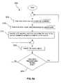
- FIG. 5 ais an illustration of a method of transmitting rank indicator control signals according to an embodiment of the disclosure.
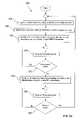
- FIG. 5 bis an illustration of another method of transmitting rank indicator control signals according to an embodiment of the disclosure.
- FIG. 6is a diagram of a wireless communications system including a user equipment operable for some of the various embodiments of the disclosure.
- FIG. 7is a block diagram of a user equipment operable for some of the various embodiments of the disclosure.
- FIG. 8is a diagram of a software environment that may be implemented on a user equipment operable for some of the various embodiments of the disclosure.
- FIG. 9illustrates an exemplary general-purpose computer system suitable for implementing the several embodiments of the present disclosure.
- a user equipmentincludes a processor configured to transmit a rank indicator (RI) using one of an assigned periodic RI reporting resource that precisely aligns with the start of an on-duration of a discontinuous reception (DRX) operation mode of the UE and a first assigned periodic RI reporting resource after the start of the on-duration.
- RIrank indicator
- a UEin other embodiments, includes a processor configured to transmit a rank indicator (RI) using a first assigned periodic RI reporting resource after the start of a retransmission window.
- RIrank indicator
- a methodfor transmitting a control signal from a user equipment (UE) to an enhanced node B (ENB).
- the methodincludes determining when an on-duration of a discontinuous reception (DRX) operation mode of the UE is scheduled, and beginning a periodic transmission of a rank indicator (RI) control signal using one of an assigned periodic RI reporting interval that precisely aligns with the start of an on-duration of a discontinuous reception (DRX) operation mode of the UE and a first assigned periodic RI reporting interval after the start of the on-duration.
- DRXdiscontinuous reception
- RIrank indicator
- FIG. 1illustrates an embodiment of a wireless telecommunications system 100 that includes a UE 10 capable of communicating with an ENB 20 or a similar component. Transmissions of various types of information can take place between the UE 10 and the ENB 20 .
- the UE 10might send the ENB 20 various types of application layer data such as VoIP data packets and data packets containing information related to web browsing, emailing, and other user applications, all of which may be referred to as user plane data.
- Other types of information related to the UE's application layerwill be familiar to one of skill in the art. Any signal containing such information will be referred to herein as a data signal 30 .
- Information associated with a data signal 30will be referred to herein as user plane data.
- the UE 10might also send the ENB 20 various types of control signaling such as layer 1 scheduling requests, layer 1 control signaling (CQI, PMI, RI, NACK/ACK, etc.), high layer radio resource control (RRC) messages and mobility measurement messages, and other control messages, all of which may be referred to as control plane data, and is familiar to one of skill in the art.
- the UE 10typically generates such messages as needed to initiate or maintain a call. Any such signal will be referred to herein as a control signal 40 .
- Information associated with a control signal 40will be referred to herein as control plane data.
- Rank indicator (RI) control signals and/or messagesare included among these control signals.
- An RI control signalmay be a message transmitted from the UE 10 to the ENB 20 and may be considered to provide channel state indication (CSI) feedback from the UE 10 to the ENB 20 .
- the RImay indicate how many independent data streams may be transmitted by the ENB 20 over the wireless link.
- the RImay be used by the ENB 20 to adapt communication parameters including modulation parameters, coding rate parameters, and other communication parameters.
- the ENB 20may select a precoding matrix based at least in part on the value of the RI transmitted from the UE 10 to the ENB 20 .
- a dedicated channelmight exist between the UE 10 and the ENB 20 via which control plane data may be sent. Requests to send data on the uplink may also use this dedicated channel. This may be called a scheduling request.
- a random access channelRACH
- a request for resources to send control plane datamay be sent via a RACH, and, in other cases, the control plane data itself might be sent via a RACH.
- the ENB 20When the UE 10 sends a control signal 40 to the ENB 20 , the ENB 20 might return a response signal or other control signal to the UE 10 . For example, if the UE 10 sends a mobility measurement message to the ENB 20 , the ENB 20 might respond by sending an acknowledgement message or some other handover-related control message to the UE 10 . Other types of responses that the ENB 20 might send upon receiving a control signal 40 from the UE 10 will be familiar to one of skill in the art. Any such response by the ENB 20 to a control signal 40 sent by the UE 10 will be referred to herein as a response signal 50 .
- the UE 10might periodically alternate between a high-power mode and a low-power mode. For example, using techniques known as discontinuous reception (DRX), the UE 10 might periodically enter short periods of relatively high power consumption during which data can be received. Such periods will be referred to herein as on-durations and/or active time. Between the on-durations, the UE 10 might enter longer periods in which power consumption is reduced and data is not received. Such periods will be referred to herein as off-durations. A balance between power savings and performance can be achieved by making the off-durations as long as possible while still keeping the on-durations long enough for the UE 10 to properly receive data.
- DRXdiscontinuous reception
- DRXis used generically to refer to discontinuous reception.
- the terms “on-duration” and “off-duration”may also be used herein to refer to a UE's capability to receive data.
- the active timedefines the time that the UE is awake, which could be longer than the on-duration due to the possible inactivity timer running which will keep the UE awake for additional time. Additional related discussion is found in 3 rd Generation Partnership Project (3GPP) Technical Specification (TS) 36.321.
- FIG. 2illustrates an idealized view of on-durations and off-durations for the UE 10 .
- On-durations 210 with higher power usagealternate in time with off-durations 220 with lower power usage.
- the UE 10receives data only during the on-durations 210 and does not receive data during the off-durations 220 .
- an entire cycle of one on-duration 210 and one off-duration 220should last 20 milliseconds. Of this cycle, it might be determined that an on-duration 210 of 5 milliseconds is sufficient for the UE 10 to receive data without significant loss of information.
- the off-duration 220would then last 15 milliseconds.
- the determination of the sizes of the on-durations 210 and the off-durations 220might be based on the quality of service (QoS) parameters of an application. For example, a VoIP call might need a higher level of quality (e.g., less delay) than an email transmission.
- QoSquality of service
- the UE 10 and the ENB 20enter a service negotiation stage in which a QoS is negotiated based on the maximum allowable delay, the maximum allowable packet loss, and similar considerations.
- the level of service to which the user of the UE 10 subscribesmight also be a factor in the QoS negotiations.
- the ENB 20sets the appropriate sizes for the on-durations 210 and the off-durations 220 based on that QoS level.
- a plurality of assigned periodic RI reporting intervals 250are shown relative to the on-duration 210 and a retransmission window 230 .
- the assigned periodic RI reporting intervals 250may be referred to as assigned periodic RI reporting resources.
- the RI reporting intervals 250 depictedinclude a first RI reporting interval 250 a , a second RI reporting interval 250 b , a third RI reporting interval 250 c , a fourth RI reporting interval 250 d , a fifth RI reporting interval 250 e , a sixth RI reporting interval 250 f , a seventh RI reporting interval 250 g , an eighth RI reporting interval 250 h , a ninth RI reporting interval 250 i , a tenth RI reporting interval 250 j , an eleventh RI reporting interval 250 k , and a twelfth RI reporting interval 250 l .
- the assigned periodic RI reporting intervals 250 in a networkis an ongoing sequence, and that many RI reporting intervals 250 precede the first RI reporting interval 250 a and many RI reporting intervals 250 follow the twelfth RI reporting interval 250 l .
- the UE 10may transmit RI control signals during each RI reporting interval 250 using the assigned RI reporting resources, as indicated in FIG. 3 a by the solid line arrows.
- the retransmission window 230provides an opportunity for the ENB 20 to retransmit data to the UE 10 that the UE 10 was unable to receive properly during the on-duration 210 .
- the UE 10may transmit some of the PMI control signals during the on duration 210 and the retransmission window 230 .
- the UE 10may require that the UE 10 have two or more antennas with two different RF chains—a first RF chain associated with a first antenna for receiving and a second RF chain associated with a second antenna for transmitting—so the UE 10 can receive and transmit concurrently.
- RI control signal transmissionsare discussed further.
- the ENB 20may not transmitting to the UE 10 , there may be no benefit associated with the UE 10 sending RI control signals to the ENB 20 , because the ENB 20 need not adapt communication parameters for communicating with the UE 10 at that time.
- a wide variety of techniquesmay be employed to reduce the transmissions of RI control signals. As depicted in FIG.
- the UE 10may turn off or stop transmitting RI control signals during the first RI reporting interval 250 a , the second RI reporting interval 250 b and during the fifth RI reporting interval 250 e through the twelfth RI reporting interval 250 l , thereby saving the power that otherwise would have been consumed by transmitting the RI control signals during the RI reporting intervals 250 a , 250 b , 250 e , 250 f , 250 g , 250 h , 250 i , 250 j , 250 k , and 250 l .
- the UE 10analyzes the schedule of the on-duration 210 and determines to transmit on one of the RI reporting intervals 250 during the first RI reporting interval after the start of the on-duration 210 and to continue to transmit the RI control signal during each successive RI reporting interval until the end of the on-duration 210 or the end of the active time.
- the UE 10may be instructed by the ENB 20 that it should suspend transmitting RI until the end of the on-duration 210 or the end of the active time. It is understood that each of the RI control signals transmitted by the UE 10 is independent of the other RI control signals transmitted by the UE 10 and may contain new information based on current radio channel conditions.
- the UE 10may transmit the RI control signal during the RI reporting interval that immediately precedes the on-duration 210 and continues to transmit the RI control signal during each successive RI reporting interval 250 until the end of the on-duration or the end of the active time.
- the ENB 20may be able to receive the RI control signal from the UE 10 , to process the RI information, and to determine how to adapt communication parameters by the start of the on-duration 210 . In some contexts this may be referred to as resuming RI control signal transmissions.
- the UE 10continues to periodically transmit the RI control signals until the retransmission window 230 has ended, then the UE 10 stops transmitting RI control signals.
- the UE 10may begin transmitting the RI control signal either during the first RI reporting interval 250 of the on-duration 210 , for example the third RI reporting interval 250 c as depicted in FIG. 3 b , or during the RI reporting interval 250 that immediately precedes the on-duration, for example the second RI reporting interval 250 b , as depicted in FIG. 3 c .
- FIG. 3 cAs an example, in FIG.
- the UE 10is depicted as periodically transmitting RI control signals from the third RI reporting interval 250 c through the eighth RI reporting interval 250 h .
- This scenariomay also be described as transmitting the RI control signal during a first assigned periodic RI reporting resource after the start of the on-duration 210 and transmitting the RI control signal during each successive assigned periodic RI reporting resource until the end of the retransmission window 230 .
- RI control signal transmissionsare discussed further. It may be inefficient for the UE 10 to transmit RI control signals after the on-duration 210 has concluded or stopped and before the retransmission window 230 begins.
- the UE 10analyzes the schedule of the on-duration 210 and may turn off or stop periodic transmissions of the RI control signal after the on-duration 210 has ended or at the end of the active time. For example, as depicted in FIG.
- the UE 10may turn on periodic transmission of RI control signals during the third RI reporting interval 250 c through the fourth RI reporting interval 250 d , turn off periodic transmission of RI control signals during the fifth RI reporting interval 250 e through the seventh RI reporting interval 250 g , turn on or resume periodic transmission of RI control signals for the eighth RI reporting interval 250 h , and then turn off periodic transmission of RI control signals at the ninth RI reporting interval 250 i .
- the UE 10may also transmit the RI control signal during the seventh RI reporting interval 250 g.
- RI control signal transmissionsare discussed further.
- the UE 10may begin transmitting the RI control signal with the first RI reporting interval 250 in the retransmission window 230 or with the RI reporting interval 250 that immediately precedes the retransmission window 230 and to transmit RI control signals during each successive RI reporting interval 250 until the end of the retransmission window 230 .
- RI control signal transmission scenariosadmit of a variety of related combinations and extensions along the lines of the description above. All of these combinations and extensions are contemplated by the present disclosure. Additional technical details related to discontinuous reception (DRX) operation modes and assigned periodic RI reporting resources may be found in TS 36.300, TS 36.321, and TS 36.213, each of which are hereby incorporated herein by reference for all purposes.
- DRXdiscontinuous reception
- FIG. 4 athe timing relationship between the RI reporting intervals 250 and a plurality of uplink sub-frames and downlink sub-frames of an ENB is discussed.
- a number of time lagsare observed between the UE 10 transmitting the RI control signal and the ENB 20 adapting the communication parameters based on the RI control signals.
- a propagation delayis introduced by the time it takes for the radio frequency signal emitted by the UE 10 containing the RI control signal to propagate through the radio channel to the ENB 20 .
- the ENB 20 processingis segmented into uplink sub-frames 260 and downlink sub-frames 270 , for example a first uplink sub-frame 260 a , a second uplink sub-frame 260 b , a third uplink sub-frame 260 c , a first downlink sub-frame 270 a , a second downlink sub-frame 270 b , and a third downlink sub-frame 270 c .
- the timing of the uplink sub-frame 260 edges and the downlink sub-frame 270 edgesmay not align due to the propagation delay and/or oscillator drift between the UE 10 and the ENB 20 .
- the RI control signal transmitted during the third RI reporting interval 250 cmay be received by the ENB 20 in the first uplink sub-frame 260 a , processed by the ENB 20 to adapt communication parameters in the second uplink sub-frame 260 b , and the newly adapted communication parameters may be employed by the ENB 20 for communicating with the UE 10 during the third downlink sub-frame 270 c .
- the best case sub-frame delayis about two sub-frames.
- the sub-frame delaymay be about three sub-frames or about four sub-frames.
- the UE 10takes the time lags discussed above with reference to FIG. 4 a into account in determining when to begin periodic transmission of the RI control signal before the on-duration 210 and before the retransmission window 230 .
- beginning periodic transmission of the RI control signal with the third RI reporting interval 250 cmay not provide enough lead time for the ENB 20 to receive, process, and adapt communication parameters by the beginning of the on-duration 210 .
- the first downlink sub-frame and also possibly the second downlink sub-framemay not benefit from adaptation based on a fresh RI control signal and less efficient communication operation between the UE 10 and the ENB 20 may result.
- the ENB 20may use the previously transmitted RI control signal that does not suit the current radio channel and result in inefficient use of the radio channel.
- the ENB 20may use a lower modulation rate and/or a lower coding rate than current channel conditions support.
- the ENB 20may use a higher modulation rate and/or a higher coding rate than current channel conditions support, the UE 10 may fail to receive one or more data packets, for example, and the ENB 20 may need to retransmit the data packets using HARQ, possibly decreasing the throughput of the radio channel and increasing the UE 10 power consumption for waking up to listen to the retransmissions.
- the UE 10begins periodic transmission of RI control signals with the second RI reporting interval 250 b , thereby providing enough time to permit the ENB 20 to receive the RI control signal, process the RI control signal, and adapt communication parameters by the start of the on-duration 210 .
- the UE 10determines when to start or resume periodic transmission of the RI control signal before the retransmission window 230 taking into account the time needed by the ENB 20 to receive the RI control signal, process the RI control signal, and adapt communication parameters by the start of the retransmission window 230 .
- the ENB 20may instruct the UE 10 how to determine when to start or resume periodic transmission of the RI control signal before the retransmission window 230 .
- the UE 10determines when the next on-duration 210 is scheduled.
- the ENB 20may instruction the UE 10 to begin this process.
- the UE 10determines when the retransmission window 230 associated with the on-duration 210 is scheduled.
- the UE 10identifies or selects a RI reporting interval 250 that precedes the start of the on-duration 210 . In an embodiment, the UE 10 may select any RI reporting interval 250 that precedes the start of the on-duration 210 .
- the UE 10may select the RI reporting interval 250 that immediately precedes the start of the on-duration 210 . Another way of describing the behavior of this embodiment is that the UE 10 may select the last RI reporting interval 250 that occurs before the start of the on-duration 210 . In another embodiment, the UE 10 takes into account the time lags of radio frequency signal propagation, timing offsets associated with oscillator drifts, and processing by the ENB 20 to select the RI reporting interval 250 that precedes the on-duration 210 . In an embodiment, the UE 10 may estimate the time lags to consume about a time duration of two sub-frames.
- the UE 10may estimate the time lags to consume about a time duration of three sub-frames or four sub-frames. In some circumstances, depending on timing alignments between the on-duration 210 , the UE 10 may select the last RI reporting interval 250 that occurs before the start of the on-duration 210 or the UE 10 may select the next to the last RI reporting interval 250 that occurs before the start of the on-duration 210 . In another embodiment, however, the UE 10 may select the first RI reporting interval after the start of the on-duration 210 . The UE 10 may select the first RI reporting interval as the precise start of the on-duration 210 , when the RI reporting interval 250 precisely aligns with the start of the on-duration 210 .
- the UE 10transmits the RI control signal on the selected RI reporting interval 250 .
- the processing of block 320may include a waiting process or a sleeping process wherein the process 300 only executes block 320 at the appropriate time, for example at the time of the selected RI reporting interval 250 .
- the process 300returns to block 320 .
- the UE 10periodically transmits the RI control signal to the ENB 20 .
- the UE 10re-determines the RI values and/or information for each new transmission of the RI control signal. It is also understood that the UE 10 transmits the RI control signal at about the assigned time of the RI reporting interval 250 over assigned RI reporting resources.
- the processingreturns to block 305 .
- Thiscan be understood to include stopping periodic transmission of RI control signals until the method 300 returns to block 320 .
- the UE 10determines when the next on-duration 210 is scheduled to begin and to end.
- the UE 10determines when the retransmission window 230 associated with the next on-duration 210 is scheduled to begin and end.
- the UE 10identifies or selects the RI reporting interval that precedes the next scheduled on-duration 210 to start periodic RI control signal transmissions. As described with respect to block 315 above, the UE 10 may select the RI reporting interval according to several different selection criteria, all of which are also contemplated by the method 350 .
- the UE 10transmits the RI control signal on the selected RI reporting interval 250 .
- the processing of block 370may include a waiting process or a sleeping process wherein the process 350 only executes block 370 at the appropriate time, for example at the time of the selected RI reporting interval 250 .
- the method 350returns to block 370 .
- the UE 10periodically transmits the RI control signal to the ENB 20 .
- the UE 10re-determines the RI values and/or information for each new transmission of the RI control signal. It is also understood that the UE 10 transmits the RI control signal at about the assigned time of the RI reporting interval 250 over assigned RI reporting resources.
- the processingproceeds to block 380 .
- the UE 10identifies or selects the RI reporting interval that precedes the retransmission window 230 to start or resume periodic RI control signal transmissions. As described with respect to block 315 above, the UE 10 may select the RI reporting interval according to several different selection criteria, all of which are also contemplated by method 350 . In another embodiment, however, after on-duration 210 has completed the method 350 may complete and no RI control signals may be transmitted during the retransmission window 230 . In still another embodiment, the method 350 may begin at block 360 , jump from block 360 to block 380 , bypassing blocks 355 , 365 , 370 , and 375 .
- the UE 10transmits the RI control signal on the selected RI reporting interval 250 .
- the processing of block 385may include a waiting process or a sleeping process wherein the process 350 only executes block 385 at the appropriate time, for example at the time of the selected RI reporting interval 250 .
- the method 350returns to block 385 .
- the UE 10periodically transmits the RI control signal to the ENB 20 .
- the UE 10re-determines the RI values and/or information for each new transmission of the RI control signal. It is also understood that the UE 10 transmits the RI control signal at about the assigned time of the RI reporting interval 250 over assigned RI reporting resources.
- the processingreturns to block 355 .
- Thiscan be understood to include stopping periodic transmission of RI control signals until the method 350 returns to block 370 .
- FIG. 6illustrates a wireless communications system including an embodiment of the UE 10 .
- the UE 10is operable for implementing aspects of the disclosure, but the disclosure should not be limited to these implementations.
- the UE 10may take various forms including a wireless handset, a pager, a personal digital assistant (PDA), a portable computer, a tablet computer, or a laptop computer. Many suitable devices combine some or all of these functions.
- the UE 10is not a general purpose computing device like a portable, laptop or tablet computer, but rather is a special-purpose communications device such as a mobile phone, a wireless handset, a pager, a PDA, or a telecommunications device installed in a vehicle.
- the UE 10may be a portable, laptop or other computing device.
- the UE 10may support specialized activities such as gaming, inventory control, job control, and/or task management functions, and so on.
- the UE 10includes a display 402 .
- the UE 10includes two antennas 403 —a first antenna 403 A and a second antenna 403 B—which may be used for MIMO operations.
- the two antennas 403may also permit the UE 10 to transmit the RI control signals during the on-duration 210 and/or during the retransmission window 230 on the first antenna 403 A while concurrently receiving signals sent by the ENB 20 to the UE 10 on the second antenna 403 B.
- the UE 10also includes a touch-sensitive surface, a keyboard or other input keys generally referred as 404 for input by a user.
- the keyboardmay be a full or reduced alphanumeric keyboard such as QWERTY, Dvorak, AZERTY, and sequential types, or a traditional numeric keypad with alphabet letters associated with a telephone keypad.
- the input keysmay include a trackwheel, an exit or escape key, a trackball, and other navigational or functional keys, which may be inwardly depressed to provide further input function.
- the UE 10may present options for the user to select, controls for the user to actuate, and/or cursors or other indicators for the user to direct.
- the UE 10may further accept data entry from the user, including numbers to dial or various parameter values for configuring the operation of the UE 10 .
- the UE 10may further execute one or more software or firmware applications in response to user commands. These applications may configure the UE 10 to perform various customized functions in response to user interaction. Additionally, the UE 10 may be programmed and/or configured over-the-air, for example from a wireless base station, a wireless access point, or a peer UE 10 .
- the various applications executable by the UE 10are a web browser, which enables the display 402 to show a web page.
- the web pagemay be obtained via wireless communications with a wireless network access node, a cell tower, a peer UE 10 , or any other wireless communication network or system 400 .
- the network 400is coupled to a wired network 408 , such as the Internet.
- the UE 10has access to information on various servers, such as a server 410 .
- the server 410may provide content that may be shown on the display 402 .
- the UE 10may access the network 400 through a peer UE 10 acting as an intermediary, in a relay type or hop type of connection.
- FIG. 7shows a block diagram of the UE 10 . While a variety of known components of UEs 10 are depicted, in an embodiment a subset of the listed components and/or additional components not listed may be included in the UE 10 .
- the UE 10includes a digital signal processor (DSP) 502 and a memory 504 .
- DSPdigital signal processor
- the UE 10may further include a front end unit 506 , a radio frequency (RF) transceiver 508 , an analog baseband processing unit 510 , a microphone 512 , an earpiece speaker 514 , a headset port 516 , an input/output interface 518 , a removable memory card 520 , a universal serial bus (USB) port 522 , a short range wireless communication sub-system 524 , an alert 526 , a keypad 528 , a liquid crystal display (LCD), which may include a touch sensitive surface 530 , an LCD controller 532 , a charge-coupled device (CCD) camera 534 , a camera controller 536 , and a global positioning system (GPS) sensor 538 .
- the UE 10may include another kind of display that does not provide a touch sensitive screen.
- the DSP 502may communicate directly with the memory 504 without passing through the input/output interface 518 .
- the front end unit 506interfaces with the two antennas 403 and may comprise one receive chain and one transmit chain.
- One antenna 403is for transmitting and the other antenna 403 is for receiving. This allows the UE 10 to transmit the RI signals at the same time it is receiving control and/or data information from the ENB 20 .
- the DSP 502or some other form of controller or central processing unit operates to control the various components of the UE 10 in accordance with embedded software or firmware stored in memory 504 or stored in memory contained within the DSP 502 itself.
- the DSP 502may execute other applications stored in the memory 504 or made available via information carrier media such as portable data storage media like the removable memory card 520 or via wired or wireless network communications.
- the application softwaremay comprise a compiled set of machine-readable instructions that configure the DSP 502 to provide the desired functionality, or the application software may be high-level software instructions to be processed by an interpreter or compiler to indirectly configure the DSP 502 .
- the antenna and front end unit 506may be provided to convert between wireless signals and electrical signals, enabling the UE 10 to send and receive information from a cellular network or some other available wireless communications network or from a peer UE 10 .
- the antenna and front end unit 506may include multiple antennas to support beam forming and/or multiple input multiple output (MIMO) operations.
- MIMO operationsmay provide spatial diversity which can be used to overcome difficult channel conditions and/or increase channel throughput.
- the antenna and front end unit 506may include antenna tuning and/or impedance matching components, RF power amplifiers, and/or low noise amplifiers.
- the RF transceiver 508provides frequency shifting, converting received RF signals to baseband and converting baseband transmit signals to RF.
- a radio transceiver or RF transceivermay be understood to include other signal processing functionality such as modulation/demodulation, coding/decoding, interleaving/deinterleaving, spreading/despreading, inverse fast Fourier transforming (IFFT)/fast Fourier transforming (FFT), cyclic prefix appending/removal, and other signal processing functions.
- IFFTinverse fast Fourier transforming
- FFTfast Fourier transforming
- cyclic prefix appending/removaland other signal processing functions.
- the description hereseparates the description of this signal processing from the RF and/or radio stage and conceptually allocates that signal processing to the analog baseband processing unit 510 and/or the DSP 502 or other central processing unit.
- the analog baseband processing unit 510may provide various analog processing of inputs and outputs, for example analog processing of inputs from the microphone 512 and the headset 516 and outputs to the earpiece 514 and the headset 516 .
- the analog baseband processing unit 510may have ports for connecting to the built-in microphone 512 and the earpiece speaker 514 that enable the UE 10 to be used as a cell phone.
- the analog baseband processing unit 510may further include a port for connecting to a headset or other hands-free microphone and speaker configuration.
- the analog baseband processing unit 510may provide digital-to-analog conversion in one signal direction and analog-to-digital conversion in the opposing signal direction.
- at least some of the functionality of the analog baseband processing unit 510may be provided by digital processing components, for example by the DSP 502 or by other central processing units.
- the DSP 502may perform modulation/demodulation, coding/decoding, interleaving/deinterleaving, spreading/despreading, inverse fast Fourier transforming (IFFT)/fast Fourier transforming (FFT), cyclic prefix appending/removal, and other signal processing functions associated with wireless communications.
- IFFTinverse fast Fourier transforming
- FFTfast Fourier transforming
- cyclic prefix appending/removaland other signal processing functions associated with wireless communications.
- CDMAcode division multiple access
- the DSP 502may perform modulation, coding, interleaving, inverse fast Fourier transforming, and cyclic prefix appending, and for a receiver function the DSP 502 may perform cyclic prefix removal, fast Fourier transforming, deinterleaving, decoding, and demodulation.
- OFDMAorthogonal frequency division multiplex access
- the DSP 502may communicate with a wireless network via the analog baseband processing unit 510 .
- the communicationmay provide Internet connectivity, enabling a user to gain access to content on the Internet and to send and receive e-mail or text messages.
- the input/output interface 518interconnects the DSP 502 and various memories and interfaces.
- the memory 504 and the removable memory card 520may provide software and data to configure the operation of the DSP 502 .
- the interfacesmay be the USB interface 522 and the short range wireless communication sub-system 524 .
- the USB interface 522may be used to charge the UE 10 and may also enable the UE 10 to function as a peripheral device to exchange information with a personal computer or other computer system.
- the short range wireless communication sub-system 524may include an infrared port, a Bluetooth interface, an IEEE 802.11 compliant wireless interface, or any other short range wireless communication sub-system, which may enable the UE 10 to communicate wirelessly with other nearby mobile devices and/or wireless base stations.
- the input/output interface 518may further connect the DSP 502 to the alert 526 that, when triggered, causes the UE 10 to provide a notice to the user, for example, by ringing, playing a melody, or vibrating.
- the alert 526may serve as a mechanism for alerting the user to any of various events such as an incoming call, a new text message, and an appointment reminder by silently vibrating, or by playing a specific pre-assigned melody for a particular caller.
- the keypad 528couples to the DSP 502 via the interface 518 to provide one mechanism for the user to make selections, enter information, and otherwise provide input to the UE 10 .
- the keyboard 528may be a full or reduced alphanumeric keyboard such as QWERTY, Dvorak, AZERTY and sequential types, or a traditional numeric keypad with alphabet letters associated with a telephone keypad.
- the input keysmay include a trackwheel, an exit or escape key, a trackball, and other navigational or functional keys, which may be inwardly depressed to provide further input function.
- Another input mechanismmay be the LCD 530 , which may include touch screen capability and also display text and/or graphics to the user.
- the LCD controller 532couples the DSP 502 to the LCD 530 .
- the CCD camera 534if equipped, enables the UE 10 to take digital pictures.
- the DSP 502communicates with the CCD camera 534 via the camera controller 536 .
- a camera operating according to a technology other than Charge Coupled Device camerasmay be employed.
- the GPS sensor 538is coupled to the DSP 502 to decode global positioning system signals, thereby enabling the UE 10 to determine its position.
- Various other peripheralsmay also be included to provide additional functions, e.g., radio and television reception.
- FIG. 8illustrates a software environment 602 that may be implemented by the DSP 502 .
- the DSP 502executes operating system drivers 604 that provide a platform from which the rest of the software operates.
- the operating system drivers 604provide drivers for the wireless device hardware with standardized interfaces that are accessible to application software.
- the operating system drivers 604include application management services (“AMS”) 606 that transfer control between applications running on the UE 10 .
- AMSapplication management services
- FIG. 8are also shown in FIG. 8 a web browser application 608 , a media player application 610 , and Java applets 612 .
- the web browser application 608configures the UE 10 to operate as a web browser, allowing a user to enter information into forms and select links to retrieve and view web pages.
- the media player application 610configures the UE 10 to retrieve and play audio or audiovisual media.
- the Java applets 612configure the UE 10 to provide games, utilities, and other functionality.
- a component 614might provide functionality related to RI transmission during DRX as described herein. Although the component 614 is shown in FIG. 8 at an application software level, the component 614 may be implemented at a lower system level than is illustrated in FIG. 8 .
- FIG. 9illustrates a typical, general-purpose computer system suitable for implementing aspects of one or more embodiments disclosed herein.
- the computer system 680includes a processor 682 (which may be referred to as a central processor unit or CPU) that is in communication with memory devices including secondary storage 684 , read only memory (ROM) 686 , random access memory (RAM) 688 , input/output (I/O) devices 690 , and network connectivity devices 692 .
- the processor 682may be implemented as one or more CPU chips.
- the secondary storage 684is typically comprised of one or more disk drives or tape drives and is used for non-volatile storage of data and as an over-flow data storage device if RAM 688 is not large enough to hold all working data. Secondary storage 684 may be used to store programs which are loaded into RAM 688 when such programs are selected for execution.
- the ROM 686is used to store instructions and perhaps data which are read during program execution. ROM 686 is a non-volatile memory device which typically has a small memory capacity relative to the larger memory capacity of secondary storage.
- the RAM 688is used to store volatile data and perhaps to store instructions. Access to both ROM 686 and RAM 688 is typically faster than to secondary storage 684 .
- I/O devices 690may include printers, video monitors, liquid crystal displays (LCDs), touch screen displays, keyboards, keypads, switches, dials, mice, track balls, voice recognizers, card readers, paper tape readers, or other well-known input devices.
- LCDsliquid crystal displays
- touch screen displayskeyboards, keypads, switches, dials, mice, track balls, voice recognizers, card readers, paper tape readers, or other well-known input devices.
- the network connectivity devices 692may take the form of modems, modem banks, ethernet cards, universal serial bus (USB) interface cards, serial interfaces, token ring cards, fiber distributed data interface (FDDI) cards, wireless local area network (WLAN) cards, radio transceiver cards such as code division multiple access (CDMA) and/or global system for mobile communications (GSM) radio transceiver cards, and other well-known network devices.
- These network connectivity devices 692may enable the processor 682 to communicate with an Internet or one or more intranets. With such a network connection, it is contemplated that the processor 682 might receive information from the network, or might output information to the network in the course of performing the above-described method steps.
- Such informationmay be received from and outputted to the network, for example, in the form of a computer data signal embodied in a carrier wave.
- the network connectivity devices 692may also include one or more transmitter and receivers for wirelessly or otherwise transmitting and receiving signal as are well know to one of ordinary skill in the art.
- Such informationmay be received from and outputted to the network, for example, in the form of a computer data baseband signal or signal embodied in a carrier wave.
- the baseband signal or signal embodied in the carrier wave generated by the network connectivity devices 692may propagate in or on the surface of electrical conductors, in coaxial cables, in waveguides, in optical media, for example optical fiber, or in the air or free space.
- the information contained in the baseband signal or signal embedded in the carrier wavemay be ordered according to different sequences, as may be desirable for either processing or generating the information or transmitting or receiving the information.
- the baseband signal or signal embedded in the carrier wave, or other types of signals currently used or hereafter developed, referred to herein as the transmission mediummay be generated according to several methods well known to one skilled in the art.
- the processor 682executes instructions, codes, computer programs, scripts which it accesses from hard disk, floppy disk, optical disk (these various disk based systems may all be considered secondary storage 684 ), ROM 686 , RAM 688 , or the network connectivity devices 692 . While only one processor 682 is shown, multiple processors may be present. Thus, while instructions may be discussed as executed by a processor, the instructions may be executed simultaneously, serially, or otherwise executed by one or multiple processors.
Landscapes
- Engineering & Computer Science (AREA)
- Computer Networks & Wireless Communication (AREA)
- Signal Processing (AREA)
- Quality & Reliability (AREA)
- Databases & Information Systems (AREA)
- Mobile Radio Communication Systems (AREA)
- Measuring Pulse, Heart Rate, Blood Pressure Or Blood Flow (AREA)
- Road Signs Or Road Markings (AREA)
- Financial Or Insurance-Related Operations Such As Payment And Settlement (AREA)
- Detection And Prevention Of Errors In Transmission (AREA)
Abstract
Description
Claims (24)
Priority Applications (28)
| Application Number | Priority Date | Filing Date | Title |
|---|---|---|---|
| US12/058,444US8199725B2 (en) | 2008-03-28 | 2008-03-28 | Rank indicator transmission during discontinuous reception |
| CA2914873ACA2914873C (en) | 2008-03-28 | 2009-03-04 | Rank indicator transmission during discontinuous reception |
| AU2009228889AAU2009228889B2 (en) | 2008-03-28 | 2009-03-04 | Rank indicator transmission during discontinuous reception |
| MX2010010636AMX2010010636A (en) | 2008-03-28 | 2009-03-04 | Rank indicator transmission during discontinuous reception. |
| HK11110678.5AHK1156461B (en) | 2008-03-28 | 2009-03-04 | Rank indicator transmission during discontinuous reception |
| CN201410111077.6ACN103906036B (en) | 2008-03-28 | 2009-03-04 | The order designator of discontinuous reception period is sent |
| PCT/US2009/036013WO2009120465A2 (en) | 2008-03-28 | 2009-03-04 | Rank indicator transmission during discontinuous reception |
| KR1020127023475AKR101556436B1 (en) | 2008-03-28 | 2009-03-04 | Rank indicator transmission during discontinuous reception |
| CA2719818ACA2719818C (en) | 2008-03-28 | 2009-03-04 | Rank indicator transmission during discontinuous reception |
| CN200980111154.5ACN102017760B (en) | 2008-03-28 | 2009-03-04 | Rank indicator transmission during discontinuous reception |
| KR1020117027613AKR101478871B1 (en) | 2008-03-28 | 2009-03-04 | Rank indicator transmission during discontinuous reception |
| KR1020107024169AKR101384315B1 (en) | 2008-03-28 | 2009-03-04 | Rank indicator transmission during discontinuous reception |
| JP2011501875AJP2011520317A (en) | 2008-03-28 | 2009-03-04 | Rank indicator transmission during discontinuous reception |
| ES14163883.3TES2587506T3 (en) | 2008-03-28 | 2009-03-18 | Transmission of range indicator during discontinuous reception |
| EP18156349.5AEP3340727B1 (en) | 2008-03-28 | 2009-03-18 | Rank indicator transmission during discontinuous reception |
| EP14163883.3AEP2755439B1 (en) | 2008-03-28 | 2009-03-18 | Rank indicator transmission during discontinuous reception |
| AT09155546TATE536073T1 (en) | 2008-03-28 | 2009-03-18 | RANK INDICATOR TRANSMISSION DURING DISCONTINUOUS RECEPTION |
| EP09155546AEP2106189B1 (en) | 2008-03-28 | 2009-03-18 | Rank indicator transmission during discontinuous reception |
| ES09155546TES2378606T3 (en) | 2008-03-28 | 2009-03-18 | Transmission of range indicator during discontinuous reception |
| EP11191226.7AEP2458928B1 (en) | 2008-03-28 | 2009-03-18 | Rank indicator transmission during discontinuous reception |
| EP12156166.6AEP2458929B1 (en) | 2008-03-28 | 2009-03-18 | Rank indicator transmission during discontinuous reception |
| EP12156271.4AEP2482608B1 (en) | 2008-03-28 | 2009-03-18 | Rank indicator transmission during discontinuous reception |
| ES12156166.6TES2656550T3 (en) | 2008-03-28 | 2009-03-18 | Transmission of the range indicator during discontinuous reception |
| US13/467,937US8818438B2 (en) | 2008-03-28 | 2012-05-09 | Rank indicator transmission during discontinuous reception |
| HK14112770.5AHK1199347B (en) | 2008-03-28 | 2012-11-26 | Rank indicator transmission during discontinuous reception |
| US14/179,227US9055570B2 (en) | 2008-03-28 | 2014-02-12 | Rank indicator transmission during discontinuous reception |
| US14/704,526US9433002B2 (en) | 2008-03-28 | 2015-05-05 | Rank indicator transmission during discontinuous reception |
| HK18111803.4AHK1252494B (en) | 2008-03-28 | 2018-09-13 | Rank indicator transmission during discontinuous reception |
Applications Claiming Priority (1)
| Application Number | Priority Date | Filing Date | Title |
|---|---|---|---|
| US12/058,444US8199725B2 (en) | 2008-03-28 | 2008-03-28 | Rank indicator transmission during discontinuous reception |
Related Child Applications (1)
| Application Number | Title | Priority Date | Filing Date |
|---|---|---|---|
| US13/467,937ContinuationUS8818438B2 (en) | 2008-03-28 | 2012-05-09 | Rank indicator transmission during discontinuous reception |
Publications (2)
| Publication Number | Publication Date |
|---|---|
| US20090247223A1 US20090247223A1 (en) | 2009-10-01 |
| US8199725B2true US8199725B2 (en) | 2012-06-12 |
Family
ID=40843272
Family Applications (4)
| Application Number | Title | Priority Date | Filing Date |
|---|---|---|---|
| US12/058,444Active2030-11-28US8199725B2 (en) | 2008-03-28 | 2008-03-28 | Rank indicator transmission during discontinuous reception |
| US13/467,937Active2028-08-27US8818438B2 (en) | 2008-03-28 | 2012-05-09 | Rank indicator transmission during discontinuous reception |
| US14/179,227ActiveUS9055570B2 (en) | 2008-03-28 | 2014-02-12 | Rank indicator transmission during discontinuous reception |
| US14/704,526ActiveUS9433002B2 (en) | 2008-03-28 | 2015-05-05 | Rank indicator transmission during discontinuous reception |
Family Applications After (3)
| Application Number | Title | Priority Date | Filing Date |
|---|---|---|---|
| US13/467,937Active2028-08-27US8818438B2 (en) | 2008-03-28 | 2012-05-09 | Rank indicator transmission during discontinuous reception |
| US14/179,227ActiveUS9055570B2 (en) | 2008-03-28 | 2014-02-12 | Rank indicator transmission during discontinuous reception |
| US14/704,526ActiveUS9433002B2 (en) | 2008-03-28 | 2015-05-05 | Rank indicator transmission during discontinuous reception |
Country Status (11)
| Country | Link |
|---|---|
| US (4) | US8199725B2 (en) |
| EP (6) | EP2755439B1 (en) |
| JP (1) | JP2011520317A (en) |
| KR (3) | KR101384315B1 (en) |
| CN (2) | CN102017760B (en) |
| AT (1) | ATE536073T1 (en) |
| AU (1) | AU2009228889B2 (en) |
| CA (2) | CA2719818C (en) |
| ES (3) | ES2587506T3 (en) |
| MX (1) | MX2010010636A (en) |
| WO (1) | WO2009120465A2 (en) |
Cited By (8)
| Publication number | Priority date | Publication date | Assignee | Title |
|---|---|---|---|---|
| US20110158188A1 (en)* | 2008-02-01 | 2011-06-30 | Research In Motion Limited | System and Method for Uplink Timing Synchronization in Conjunction With Discontinuous Reception |
| US20120076060A1 (en)* | 2008-03-21 | 2012-03-29 | Zhijun Cai | Channel Quality Indicator Transmission Timing with Discontinuous Reception |
| US20140162673A1 (en)* | 2008-03-28 | 2014-06-12 | Blackberry Limited | Rank Indicator Transmission During Discontinuous Reception |
| US8867422B2 (en) | 2008-03-28 | 2014-10-21 | Blackberry Limited | Precoding matrix index feedback interaction with discontinuous reception |
| US20150131622A1 (en)* | 2013-11-12 | 2015-05-14 | Qualcomm Incorporated | Proactive rank index management in slte enabled modem to achieve higher throughput |
| US9854518B2 (en) | 2013-09-27 | 2017-12-26 | Apple Inc. | System and method for audio frame generation alignment with LTE transmission opportunities |
| US9872333B2 (en) | 2013-04-03 | 2018-01-16 | Apple Inc. | Method and system for scheduling application-generated data requests in discontinuous reception (DRX) mode |
| US10492137B2 (en)* | 2013-09-16 | 2019-11-26 | Samsung Electronics Co., Ltd. | Method and apparatus for controlling DRX operation in beam forming communication system |
Families Citing this family (36)
| Publication number | Priority date | Publication date | Assignee | Title |
|---|---|---|---|---|
| CN106304289B (en)* | 2008-06-13 | 2019-10-22 | 华为技术有限公司 | A method, device and system for indicating discontinuous scheduling data |
| EP2329385A4 (en)* | 2008-08-06 | 2016-09-14 | Movik Networks | Content caching in the radio access network (ran) |
| JP5350394B2 (en)* | 2008-12-02 | 2013-11-27 | パナソニック株式会社 | Terminal apparatus and transmission method |
| JP5007294B2 (en)* | 2008-12-22 | 2012-08-22 | 株式会社エヌ・ティ・ティ・ドコモ | Wireless base station |
| US9043467B2 (en) | 2009-01-30 | 2015-05-26 | Movik Networks | Adaptive chunked and content-aware pacing of multi-media delivery over HTTP transport and network controlled bit rate selection |
| KR101534865B1 (en) | 2009-06-23 | 2015-07-27 | 엘지전자 주식회사 | Method of performing link adaptation procedure |
| US9049618B2 (en)* | 2009-12-16 | 2015-06-02 | Innovative Sonic Corporation | Method and apparatus for channel measurement reports in a wireless communication system |
| CN102550006A (en)* | 2010-02-12 | 2012-07-04 | 莫维克网络公司 | Charging-invariant and origin-server-friendly transit caching in mobile networks |
| US9515773B2 (en) | 2010-04-13 | 2016-12-06 | Qualcomm Incorporated | Channel state information reporting in a wireless communication network |
| US9307431B2 (en) | 2010-04-13 | 2016-04-05 | Qualcomm Incorporated | Reporting of channel properties in heterogeneous networks |
| US9350475B2 (en) | 2010-07-26 | 2016-05-24 | Qualcomm Incorporated | Physical layer signaling to user equipment in a wireless communication system |
| US8886250B2 (en) | 2010-06-18 | 2014-11-11 | Qualcomm Incorporated | Channel quality reporting for different types of subframes |
| US20110250919A1 (en) | 2010-04-13 | 2011-10-13 | Qualcomm Incorporated | Cqi estimation in a wireless communication network |
| US9136953B2 (en) | 2010-08-03 | 2015-09-15 | Qualcomm Incorporated | Interference estimation for wireless communication |
| WO2012040608A2 (en) | 2010-09-24 | 2012-03-29 | Movik Networks | Destination learning and mobility detection in transit network device in lte & umts radio access networks |
| KR20130009365A (en)* | 2011-07-15 | 2013-01-23 | 삼성전자주식회사 | Device and method for providing packet service in wireless terminal |
| US9204329B2 (en) | 2011-07-21 | 2015-12-01 | Movik Networks | Distributed RAN information collection, consolidation and RAN-analytics |
| US9001682B2 (en) | 2011-07-21 | 2015-04-07 | Movik Networks | Content and RAN aware network selection in multiple wireless access and small-cell overlay wireless access networks |
| WO2013013237A1 (en) | 2011-07-21 | 2013-01-24 | Movik Networks | Ran analytics, control and tuning via multi-protocol, multi-domain, and multi-rat analysis |
| GB2493713B (en)* | 2011-08-12 | 2013-10-23 | Renesas Mobile Corp | Method of operating a wireless device and processing system for a wireless device |
| KR20140047394A (en)* | 2012-10-12 | 2014-04-22 | 삼성전자주식회사 | Apparatus and method for transmitting/receiving downlink channel state information in a mobile communication system |
| CN103944668B (en)* | 2013-01-18 | 2019-05-10 | 北京三星通信技术研究有限公司 | A method and device for processing uplink and downlink transmission of flexible subframes |
| CN103731871B (en)* | 2013-12-25 | 2017-02-22 | 上海华为技术有限公司 | Information configuration method and device |
| WO2016019040A1 (en) | 2014-07-29 | 2016-02-04 | Kurt Stump | Computer-implemented systems and methods of automated physiological monitoring, prognosis, and triage |
| US9426750B2 (en)* | 2014-07-29 | 2016-08-23 | Apple Inc. | Apparatus, system, and method for parallelizing UE wakeup process |
| US9560588B2 (en) | 2014-11-03 | 2017-01-31 | Apple Inc. | Apparatus, system, and method for PDCCH preparation in radio frequency circuitry |
| CN107078863B (en)* | 2014-11-06 | 2020-11-06 | 苹果公司 | Early termination of repeated transmissions for MTC |
| US20160192365A1 (en)* | 2014-12-29 | 2016-06-30 | Mediatek Inc. | Network control devices and methods of performing wireless communications between two communications apparatuses via multi-level signaling entities |
| US10224994B2 (en)* | 2016-02-26 | 2019-03-05 | Samsung Electronics Co., Ltd. | System and method of connected mode discontinuous operation in beamformed system |
| US10873439B2 (en)* | 2016-12-16 | 2020-12-22 | Samsung Electronics Co., Ltd. | Method and apparatus for multiplexing channel state information |
| US10750569B2 (en) | 2017-03-03 | 2020-08-18 | Qualcomm Incorporated | Beam management for connected mode discontinuous reception operation |
| US20180269956A1 (en) | 2017-03-14 | 2018-09-20 | Qualcomm Incorporated | Techniques and apparatuses for beam management |
| US10187131B2 (en) | 2017-06-09 | 2019-01-22 | At&T Intellectual Property I, L.P. | Facilitation of rank and precoding matrix indication determinations for multiple antenna systems with aperiodic channel state information reporting in 5G or other next generation networks |
| US10511477B2 (en) | 2017-11-30 | 2019-12-17 | Micron Technology, Inc. | Wireless devices and systems including examples of configuration during an active time period |
| WO2020236935A1 (en)* | 2019-05-21 | 2020-11-26 | Commscope Technologies Llc | Dummy downlink transmission assignments for extension of on state of discontinuous reception (drx) cycle |
| EP4005273B1 (en)* | 2019-07-31 | 2025-08-06 | ZTE Corporation | Discontinuous reception (drx) configuration for automatic neighbor relation (anr) |
Citations (45)
| Publication number | Priority date | Publication date | Assignee | Title |
|---|---|---|---|---|
| US5801661A (en) | 1994-12-19 | 1998-09-01 | Mitsubishi Denki Kabushiki Kaisha | Antenna switching circuit suitable for a radio-frequency apparatus with a built-in antenna |
| US6045043A (en) | 1996-12-31 | 2000-04-04 | On Track Innovations Ltd. | Contact/contactless data transaction card |
| US20030052168A1 (en) | 2001-09-18 | 2003-03-20 | Wong Jacob Y. | Magnetic Stripe bridge |
| US6553178B2 (en) | 1992-02-07 | 2003-04-22 | Max Abecassis | Advertisement subsidized video-on-demand system |
| US20040063430A1 (en) | 2002-09-27 | 2004-04-01 | Interdigital Technology Corporation | Mobile communications system and method for providing mobile unit handover in wireless communication systems that employ beamforming antennas |
| US20040070952A1 (en) | 2002-10-09 | 2004-04-15 | Renesas Technology Corp. | IC card and an adapter for the same |
| US20040238857A1 (en) | 2001-08-28 | 2004-12-02 | Tessera, Inc. | High frequency chip packages with connecting elements |
| EP1601224A2 (en) | 2004-05-28 | 2005-11-30 | Lucent Technologies Inc. | Method of reducing overhead in data packet communication |
| WO2007013457A1 (en) | 2005-07-27 | 2007-02-01 | Sharp Kabushiki Kaisha | Mobile communication system, mobile station apparatus, base station apparatus, mobile communication method, program and recording medium |
| WO2007051192A2 (en) | 2005-10-27 | 2007-05-03 | Qualcomm Incorporated | A method and apparatus for pre-coding for a mimo system |
| US20070133479A1 (en)* | 2005-08-26 | 2007-06-14 | Juan Montojo | Method and apparatus for packet communications in wireless systems |
| WO2007073118A1 (en) | 2005-12-22 | 2007-06-28 | Electronics And Telecommunications Research Institute | Method and apparatus for discontinuous transmission/reception operation for reducing power consumption in cellular system |
| US20070149993A1 (en) | 2001-12-27 | 2007-06-28 | Olympus Corporation | Treatment sheath for endoscopic blood vessel harvesting |
| WO2007078171A2 (en) | 2006-01-05 | 2007-07-12 | Lg Electronics Inc. | Method of transmitting feedback information in a wireless communication system |
| JP2007235446A (en) | 2006-02-28 | 2007-09-13 | Ntt Docomo Inc | Mobile station, base station, and radio channel state notification method |
| KR20070101175A (en) | 2006-04-11 | 2007-10-16 | 삼성전자주식회사 | Method and apparatus for receiving discrete packets in mobile communication system |
| KR20070104175A (en) | 2006-04-21 | 2007-10-25 | 삼성전자주식회사 | Method and apparatus for transmitting / receiving channel quality information in wireless communication system |
| US20070291728A1 (en) | 2006-06-20 | 2007-12-20 | Lars Dalsgaard | Method and system for providing interim discontinuous reception/transmission |
| WO2007149993A2 (en) | 2006-06-21 | 2007-12-27 | Qualcomm Incorporated | Network terminal with a low duty cycle |
| US20080026744A1 (en) | 2006-07-27 | 2008-01-31 | Nokia Corporation | Providing dynamically controlled CQI technique adapted for available signaling capacity |
| US20080054079A1 (en) | 2005-05-09 | 2008-03-06 | Mullen Jeffrey D | Dynamic credit card with magnetic stripe and embedded encoder and methods for using the same to provide a copy-proof credit card |
| US20080075036A1 (en) | 2006-09-27 | 2008-03-27 | Texas Instruments Incorporated | Uplink synchronization management in wireless networks |
| US20080101280A1 (en)* | 2006-09-27 | 2008-05-01 | Qualcomm Incorporated | Dynamic channel quality reporting in a wireless communication system |
| US20080099559A1 (en) | 2006-10-31 | 2008-05-01 | Macronix International Co., Ltd. | Dual Interface SIM Card Adapter with Detachable Antenna |
| US20080101268A1 (en) | 2006-10-27 | 2008-05-01 | Interdigital Technology Corporation | Method and apparatus for enhancing discontinuous reception in wireless systems |
| US20080117873A1 (en)* | 2006-10-30 | 2008-05-22 | Nokia Corporation | Additional modulation information signaling for high speed downlink packet access |
| US20080165698A1 (en) | 2007-01-08 | 2008-07-10 | Lars Dalsgaard | Method, Apparatus and System for Providing Reports on Channel Quality of a Communication System |
| US20080186892A1 (en) | 2007-02-05 | 2008-08-07 | Qualcomm Incorporated | Flexible dtx and drx in a wireless communication system |
| US20080268863A1 (en)* | 2007-04-30 | 2008-10-30 | Klaus Pedersen | Method and Apparatus for Reporting Channel Quality |
| US20080311919A1 (en) | 2007-06-18 | 2008-12-18 | Motorola, Inc. | Use of the physical uplink control channel in a 3rd generation partnership project communication system |
| US20080316950A1 (en)* | 2007-06-20 | 2008-12-25 | Qualcomm Incorporated | Methods and apparatuses for power control |
| US20090052367A1 (en) | 2007-08-20 | 2009-02-26 | Zhijun Cai | System and Method for Retransmissions in a Discontinuous Reception Configured System |
| US20090103500A1 (en) | 2007-10-23 | 2009-04-23 | Nokia Corporation | Re-transmission capability in semi-persistent transmission |
| US20090168731A1 (en) | 2007-12-31 | 2009-07-02 | Interdigital Patent Holdings, Inc. | Method and apparatus for handling interactions between measurement gap, automated repeat request, discontinuous reception and discontinuous transmission in wireless communications |
| US20090180414A1 (en) | 2006-06-16 | 2009-07-16 | Mitsubishi Electric Corporation | Mobile Communication System and Mobile Terminal |
| US20090196366A1 (en) | 2008-02-04 | 2009-08-06 | Zukang Shen | Transmission of Uplink Control Information with Data in Wireless Networks |
| US20090232118A1 (en) | 2008-03-14 | 2009-09-17 | Interdigital Patent Holdings, Inc. | Coordinated uplink transmission in lte drx operations for a wireless transmit receive unit |
| US20090239525A1 (en)* | 2008-03-21 | 2009-09-24 | Research In Motion Limited | Channel Quality Indicator Transmission Timing with Discontinuous Reception |
| US20090239568A1 (en) | 2008-03-18 | 2009-09-24 | Pierre Bertrand | Scheduling request usage in drx mode in wireless networks |
| US20090239566A1 (en) | 2008-03-19 | 2009-09-24 | Ghyslain Pelletier | Method and a Base Station for Detecting Loss of Synchronization |
| US20100232382A1 (en)* | 2009-03-12 | 2010-09-16 | Interdigital Patent Holdings, Inc. | Method and apparatus for selecting and reselecting an uplink primary carrier |
| US7844265B2 (en) | 2006-02-09 | 2010-11-30 | Motorola Mobility, Inc. | Method for aperiodic mobile assisted sleep mode |
| US20110019637A1 (en)* | 2008-03-26 | 2011-01-27 | Nokia Corporation | Reporting channel state information |
| US20110035639A1 (en)* | 2009-08-07 | 2011-02-10 | Research In Motion Limited | Method and system for handling harq operations during transmission mode changes |
| US7957360B2 (en) | 2007-01-09 | 2011-06-07 | Motorola Mobility, Inc. | Method and system for the support of a long DRX in an LTE—active state in a wireless network |
Family Cites Families (28)
| Publication number | Priority date | Publication date | Assignee | Title |
|---|---|---|---|---|
| JPWO2005034555A1 (en) | 2003-09-30 | 2007-11-22 | 松下電器産業株式会社 | Downlink channel quality information transmission method and transmission apparatus in compressed mode |
| US8971461B2 (en)* | 2005-06-01 | 2015-03-03 | Qualcomm Incorporated | CQI and rank prediction for list sphere decoding and ML MIMO receivers |
| US8489128B2 (en) | 2005-10-31 | 2013-07-16 | Qualcomm Incorporated | Efficient transmission on a shared data channel for wireless communication |
| KR101211807B1 (en) | 2006-01-05 | 2012-12-12 | 엘지전자 주식회사 | Method for managing synchronization state for mobile terminal in mobile communication system |
| AU2007212605B2 (en) | 2006-02-03 | 2010-06-17 | Interdigital Technology Corporation | Method and system for supporting multiple hybrid automatic repeat request processes per transmission time interval |
| USRE48984E1 (en) | 2006-03-07 | 2022-03-22 | Electronics And Telecommunications Research Institute | Method for reducing power consumption of a terminal in cellular system |
| US8112075B2 (en) | 2006-03-24 | 2012-02-07 | Nokia Corporation | HARQ-aware CQI reporting |
| TWI528746B (en) | 2006-03-24 | 2016-04-01 | 內數位科技公司 | Non-continuous reception (DRX) and measurement reports in the wireless network |
| KR20080111093A (en) | 2006-03-29 | 2008-12-22 | 인덕터썸코포레이션 | Transverse Flux Induction Heating Equipment and Compensator |
| EP2016689B1 (en) | 2006-05-01 | 2017-06-21 | Nokia Technologies Oy | Apparatus, method and computer program product providing uplink synchronization through use of dedicated uplink resource assignment |
| US7929962B2 (en) | 2006-05-01 | 2011-04-19 | Alcatel-Lucent Usa Inc. | Method for controlling radio communications during idle periods in a wireless system |
| US8478285B2 (en)* | 2006-06-19 | 2013-07-02 | Ntt Docomo, Inc. | Base station, mobile station, synchronization control method, and IC chip |
| JP4998680B2 (en) | 2006-06-19 | 2012-08-15 | 日本電気株式会社 | Pilot resource allocation method, channel quality measurement method and base station in mobile communication system |
| KR100938070B1 (en)* | 2006-08-31 | 2010-01-21 | 삼성전자주식회사 | Apparatus and method for data transmission / reception in a multi-antenna system and a system providing the same |
| CN101031152B (en)* | 2007-02-07 | 2010-05-26 | 重庆重邮信科通信技术有限公司 | Method for shortening user-terminal re-selection time delay under empty mode |
| US8107987B2 (en) | 2007-02-14 | 2012-01-31 | Qualcomm Incorporated | Apparatus and method for uplink power control of wireless communications |
| US20080268785A1 (en) | 2007-04-30 | 2008-10-30 | Mccoy James W | UE-autonomous CFI reporting |
| US20080305745A1 (en)* | 2007-06-05 | 2008-12-11 | Interdigital Technology Corporation | Method and apparatus for supporting uplink transmission of channel quality and coding information in a wireless communication system |
| EP2015478B1 (en) | 2007-06-18 | 2013-07-31 | LG Electronics Inc. | Method of performing uplink synchronization in wireless communication system |
| US8102809B2 (en) | 2007-06-19 | 2012-01-24 | Texas Instruments Incorporated | Time-sharing of sounding resources |
| US8014265B2 (en) | 2007-08-15 | 2011-09-06 | Qualcomm Incorporated | Eigen-beamforming for wireless communication systems |
| US20090046674A1 (en) | 2007-08-17 | 2009-02-19 | Chun Yan Gao | Method and apparatus for providing channel feedback information |
| US8284706B2 (en) | 2007-09-20 | 2012-10-09 | Qualcomm Incorporated | Semi-connected operations for wireless communications |
| WO2009041871A1 (en) | 2007-09-28 | 2009-04-02 | Telefonaktiebolaget Lm Ericsson (Publ) | A method and device for power reduction in an lte system |
| WO2009082335A1 (en) | 2007-12-21 | 2009-07-02 | Telefonaktiebolaget L M Ericsson (Publ) | A method apparatus and network node for applying conditional cqi reporting |
| US20090318177A1 (en) | 2008-02-28 | 2009-12-24 | Interdigital Patent Holdings, Inc. | Method and apparatus for lte system information update in connected mode |
| US8199725B2 (en)* | 2008-03-28 | 2012-06-12 | Research In Motion Limited | Rank indicator transmission during discontinuous reception |
| US8179828B2 (en)* | 2008-03-28 | 2012-05-15 | Research In Motion Limited | Precoding matrix index feedback interaction with discontinuous reception |
- 2008
- 2008-03-28USUS12/058,444patent/US8199725B2/enactiveActive
- 2009
- 2009-03-04MXMX2010010636Apatent/MX2010010636A/enactiveIP Right Grant
- 2009-03-04CNCN200980111154.5Apatent/CN102017760B/enactiveActive
- 2009-03-04CNCN201410111077.6Apatent/CN103906036B/enactiveActive
- 2009-03-04KRKR1020107024169Apatent/KR101384315B1/enactiveActive
- 2009-03-04JPJP2011501875Apatent/JP2011520317A/enactivePending
- 2009-03-04KRKR1020117027613Apatent/KR101478871B1/enactiveActive
- 2009-03-04CACA2719818Apatent/CA2719818C/enactiveActive
- 2009-03-04AUAU2009228889Apatent/AU2009228889B2/enactiveActive
- 2009-03-04KRKR1020127023475Apatent/KR101556436B1/enactiveActive
- 2009-03-04CACA2914873Apatent/CA2914873C/enactiveActive
- 2009-03-04WOPCT/US2009/036013patent/WO2009120465A2/enactiveApplication Filing
- 2009-03-18EPEP14163883.3Apatent/EP2755439B1/enactiveActive
- 2009-03-18EPEP12156271.4Apatent/EP2482608B1/enactiveActive
- 2009-03-18ESES14163883.3Tpatent/ES2587506T3/enactiveActive
- 2009-03-18EPEP12156166.6Apatent/EP2458929B1/enactiveActive
- 2009-03-18EPEP09155546Apatent/EP2106189B1/enactiveActive
- 2009-03-18EPEP11191226.7Apatent/EP2458928B1/enactiveActive
- 2009-03-18ESES12156166.6Tpatent/ES2656550T3/enactiveActive
- 2009-03-18EPEP18156349.5Apatent/EP3340727B1/enactiveActive
- 2009-03-18ATAT09155546Tpatent/ATE536073T1/enactive
- 2009-03-18ESES09155546Tpatent/ES2378606T3/enactiveActive
- 2012
- 2012-05-09USUS13/467,937patent/US8818438B2/enactiveActive
- 2014
- 2014-02-12USUS14/179,227patent/US9055570B2/enactiveActive
- 2015
- 2015-05-05USUS14/704,526patent/US9433002B2/enactiveActive
Patent Citations (48)
| Publication number | Priority date | Publication date | Assignee | Title |
|---|---|---|---|---|
| US6553178B2 (en) | 1992-02-07 | 2003-04-22 | Max Abecassis | Advertisement subsidized video-on-demand system |
| US5801661A (en) | 1994-12-19 | 1998-09-01 | Mitsubishi Denki Kabushiki Kaisha | Antenna switching circuit suitable for a radio-frequency apparatus with a built-in antenna |
| US6045043A (en) | 1996-12-31 | 2000-04-04 | On Track Innovations Ltd. | Contact/contactless data transaction card |
| US20040238857A1 (en) | 2001-08-28 | 2004-12-02 | Tessera, Inc. | High frequency chip packages with connecting elements |
| US20030052168A1 (en) | 2001-09-18 | 2003-03-20 | Wong Jacob Y. | Magnetic Stripe bridge |
| US20070149993A1 (en) | 2001-12-27 | 2007-06-28 | Olympus Corporation | Treatment sheath for endoscopic blood vessel harvesting |
| US20040063430A1 (en) | 2002-09-27 | 2004-04-01 | Interdigital Technology Corporation | Mobile communications system and method for providing mobile unit handover in wireless communication systems that employ beamforming antennas |
| US20040070952A1 (en) | 2002-10-09 | 2004-04-15 | Renesas Technology Corp. | IC card and an adapter for the same |
| EP1601224A2 (en) | 2004-05-28 | 2005-11-30 | Lucent Technologies Inc. | Method of reducing overhead in data packet communication |
| US20080054079A1 (en) | 2005-05-09 | 2008-03-06 | Mullen Jeffrey D | Dynamic credit card with magnetic stripe and embedded encoder and methods for using the same to provide a copy-proof credit card |
| US20100284326A1 (en) | 2005-07-27 | 2010-11-11 | Wahoh Oh | Mobile communication system, mobile station apparatus, base station apparatus, mobile communication method, program and recording medium |
| WO2007013457A1 (en) | 2005-07-27 | 2007-02-01 | Sharp Kabushiki Kaisha | Mobile communication system, mobile station apparatus, base station apparatus, mobile communication method, program and recording medium |
| EP1916859A1 (en) | 2005-07-27 | 2008-04-30 | Sharp Kabushiki Kaisha | Mobile communication system, mobile station apparatus, base station apparatus, mobile communication method, program and recording medium |
| US20070133479A1 (en)* | 2005-08-26 | 2007-06-14 | Juan Montojo | Method and apparatus for packet communications in wireless systems |
| WO2007051192A2 (en) | 2005-10-27 | 2007-05-03 | Qualcomm Incorporated | A method and apparatus for pre-coding for a mimo system |
| WO2007073118A1 (en) | 2005-12-22 | 2007-06-28 | Electronics And Telecommunications Research Institute | Method and apparatus for discontinuous transmission/reception operation for reducing power consumption in cellular system |
| WO2007078171A2 (en) | 2006-01-05 | 2007-07-12 | Lg Electronics Inc. | Method of transmitting feedback information in a wireless communication system |
| US7844265B2 (en) | 2006-02-09 | 2010-11-30 | Motorola Mobility, Inc. | Method for aperiodic mobile assisted sleep mode |
| JP2007235446A (en) | 2006-02-28 | 2007-09-13 | Ntt Docomo Inc | Mobile station, base station, and radio channel state notification method |
| KR20070101175A (en) | 2006-04-11 | 2007-10-16 | 삼성전자주식회사 | Method and apparatus for receiving discrete packets in mobile communication system |
| KR20070104175A (en) | 2006-04-21 | 2007-10-25 | 삼성전자주식회사 | Method and apparatus for transmitting / receiving channel quality information in wireless communication system |
| US20070287468A1 (en) | 2006-04-21 | 2007-12-13 | Samsung Electronics Co., Ltd | Method and apparatus for transmitting and receiving channel quality information in a wireless communication system |
| US20090180414A1 (en) | 2006-06-16 | 2009-07-16 | Mitsubishi Electric Corporation | Mobile Communication System and Mobile Terminal |
| US20070291728A1 (en) | 2006-06-20 | 2007-12-20 | Lars Dalsgaard | Method and system for providing interim discontinuous reception/transmission |
| WO2007149993A2 (en) | 2006-06-21 | 2007-12-27 | Qualcomm Incorporated | Network terminal with a low duty cycle |
| US20080026744A1 (en) | 2006-07-27 | 2008-01-31 | Nokia Corporation | Providing dynamically controlled CQI technique adapted for available signaling capacity |
| US20080075036A1 (en) | 2006-09-27 | 2008-03-27 | Texas Instruments Incorporated | Uplink synchronization management in wireless networks |
| US20080101280A1 (en)* | 2006-09-27 | 2008-05-01 | Qualcomm Incorporated | Dynamic channel quality reporting in a wireless communication system |
| US20080101268A1 (en) | 2006-10-27 | 2008-05-01 | Interdigital Technology Corporation | Method and apparatus for enhancing discontinuous reception in wireless systems |
| US20080117873A1 (en)* | 2006-10-30 | 2008-05-22 | Nokia Corporation | Additional modulation information signaling for high speed downlink packet access |
| US20080099559A1 (en) | 2006-10-31 | 2008-05-01 | Macronix International Co., Ltd. | Dual Interface SIM Card Adapter with Detachable Antenna |
| US20080165698A1 (en) | 2007-01-08 | 2008-07-10 | Lars Dalsgaard | Method, Apparatus and System for Providing Reports on Channel Quality of a Communication System |
| US7957360B2 (en) | 2007-01-09 | 2011-06-07 | Motorola Mobility, Inc. | Method and system for the support of a long DRX in an LTE—active state in a wireless network |
| US20080186892A1 (en) | 2007-02-05 | 2008-08-07 | Qualcomm Incorporated | Flexible dtx and drx in a wireless communication system |
| US20080268863A1 (en)* | 2007-04-30 | 2008-10-30 | Klaus Pedersen | Method and Apparatus for Reporting Channel Quality |
| US20080311919A1 (en) | 2007-06-18 | 2008-12-18 | Motorola, Inc. | Use of the physical uplink control channel in a 3rd generation partnership project communication system |
| US20080316950A1 (en)* | 2007-06-20 | 2008-12-25 | Qualcomm Incorporated | Methods and apparatuses for power control |
| US20090052367A1 (en) | 2007-08-20 | 2009-02-26 | Zhijun Cai | System and Method for Retransmissions in a Discontinuous Reception Configured System |
| US20090103500A1 (en) | 2007-10-23 | 2009-04-23 | Nokia Corporation | Re-transmission capability in semi-persistent transmission |
| US20090168731A1 (en) | 2007-12-31 | 2009-07-02 | Interdigital Patent Holdings, Inc. | Method and apparatus for handling interactions between measurement gap, automated repeat request, discontinuous reception and discontinuous transmission in wireless communications |
| US20090196366A1 (en) | 2008-02-04 | 2009-08-06 | Zukang Shen | Transmission of Uplink Control Information with Data in Wireless Networks |
| US20090232118A1 (en) | 2008-03-14 | 2009-09-17 | Interdigital Patent Holdings, Inc. | Coordinated uplink transmission in lte drx operations for a wireless transmit receive unit |
| US20090239568A1 (en) | 2008-03-18 | 2009-09-24 | Pierre Bertrand | Scheduling request usage in drx mode in wireless networks |
| US20090239566A1 (en) | 2008-03-19 | 2009-09-24 | Ghyslain Pelletier | Method and a Base Station for Detecting Loss of Synchronization |
| US20090239525A1 (en)* | 2008-03-21 | 2009-09-24 | Research In Motion Limited | Channel Quality Indicator Transmission Timing with Discontinuous Reception |
| US20110019637A1 (en)* | 2008-03-26 | 2011-01-27 | Nokia Corporation | Reporting channel state information |
| US20100232382A1 (en)* | 2009-03-12 | 2010-09-16 | Interdigital Patent Holdings, Inc. | Method and apparatus for selecting and reselecting an uplink primary carrier |
| US20110035639A1 (en)* | 2009-08-07 | 2011-02-10 | Research In Motion Limited | Method and system for handling harq operations during transmission mode changes |
Non-Patent Citations (57)
| Title |
|---|
| "3GPP TS 36.300 V8.4.0-3rd Generation Partnership Project; Technical Specification Group Radio Access Network; Evolved Universal Terrestrial Radio Access (E-UTRA) and Evolved Universal Terrestrial Radio Access Network (E-UTRAN); Overall description; Stage 2; Release 8"; 3GPP Organizational Partners; Jan. 2008; 126 pages. |
| 3GPP TS 36.213 V8.1.0; 3rd Generation Partnership Project; Technical Specification Group Radio Access Network; Evolved Universal Terrestrial Radio Access (E-UTRA); Physical layer procedures; Release 8; Nov. 2007; 17 pgs. |
| 3GPP TS 36.213 v8.2.0; 3rd Generation Partnership Project; Technical Specification Group Radio Access Network; Evolved Universal Terrestrial Radio Access (E-UTRA); Physical Layer Procedures; Release 8; Mar. 2008; 30 pgs. |
| 3GPP TS 36.300 V8.3.0; 3rd Generation Partnership Project; Technical Specification Group Radio Access Network; Evolved Universal Terrestrial Radio Access (E-UTRA) and Evolved Universal Terrestrial Radio Access Network (E-UTRAN); Overall description; Stage 2; Release 8; Dec. 2007; Part 1; 99 pgs. |
| 3GPP TS 36.300 V8.3.0; 3rd Generation Partnership Project; Technical Specification Group Radio Access Network; Evolved Universal Terrestrial Radio Access (E-UTRA) and Evolved Universal Terrestrial Radio Access Network (E-UTRAN); Overall description; Stage 2; Release 8; Dec. 2007; Part 2; 22 pgs. |
| '3GPP TS 36.321 V8.1.0-3rd Generation Partnership Project; Technical Specification Group Radio Access Network; Evolved Universal Terrestrial Radio Access (E-UTRA); Medium Access Control (MAC) Protocol Specification (Release 8)'; 3GPP Organizational Partners; Mar. 2008; 30 pages. |
| 3GPP TS 36.321 V8.2.0; 3rd Generation Partnership Project; Technical Specification Group Radio Access Network; Evolved Universal Terrestrial Radio Access (E-UTRA) Medium Access Control (MAC) Protocol Specification; Release 8; May 2008; 33 pgs. |
| Advisory Action issued in U.S. Appl. No. 12/058,448 on Jul. 15, 2011; 3 pages. |
| Cai, Zhijun; U.S. Appl. No. 12/052,887; "Channel Quality Indicator Transmission Timing With Discontinuous Reception"; filed Mar. 21, 2008; Specification 35 pgs; Drawing Sheets (Figs. 1-2, 3a-3c; 4a-4b; 5a-5b, 6-9). |
| Cai, Zhijun; U.S. Appl. No. 12/058,448; "Precoding Matrix Index Feedback Interaction with Discontinuous Reception"; filed Mar. 28, 2008; Specification 37 pgs; Drawing Sheets (Figs. 1-2, 3a-3f; 4a-4b; 5a-5b, 6-9). |
| Chen, Feng, et al.; Title: A Joint Unitary Precoding and Scheduling Algorithm for MIMO-OFDM System with Limited Feedback; IEEE 2007 International Symposium on Microwave, Antenna, Propagation, and EMC Technologies for Wireless Communications; pp. 9-12. |
| Communication under Rule 71(3) EPC issued in European Application No. 09155546.6 on Jul. 1, 2011; 42 pages. |
| Communication under Rule 71(3) EPC issued in European Application No. 09726227.3 on Nov. 18, 2011; 6 pages. |
| EPO Search and Examination Report; EP Application No. 09155546.6; Aug. 27, 2009; 7 pgs. |
| Ericsson; 3GPP TSG-RAN2 Meeting #62bis; Title: Clarification of DRX; Change Request; R2-083895; Warsaw, Poland; Jun. 30-Jul. 4, 2008; 3 pgs. |
| European Examination Report; EP Application No. 09155546.6; Research In Motion Limited; Feb. 10, 2010; 5 pgs. |
| European Search and Examination Report; EP Application No. 08153857.1; Aug. 21, 2008; 12 pages. |
| Examination Report issued in European Application No. 08153857.1 on Jan. 11, 2011; 9 pages. |
| Examination Report issued in European Application No. 09155546.6 on Jan. 10, 2011; 5 pages. |
| International Preliminary Report on Patentability issued in International Application No. PCT/US2009/032591 on May 19, 2010; 8 pages. |
| International Preliminary Report on Patentability issued in International Application No. PCT/US2009/036013 on Sep. 28, 2010; 6 pages. |
| International Search Report and Written Opinion of the International Searching Authority issued in International Application No. PCT/US2009/032591 on May 28, 2009; 9 pages. |
| Love, David, et al; "Grassmannian Precoding for Spatial Multiplexing Systems," The University of Texas at Austin, Austin, Texas; Oct. 2003; 3 pgs. |
| Nokia; "DRX Parameters in LTE"; 3GPP TSG-RAN WG2 Meeting #57bis; St. Julian's, Malta; Mar. 26-30, 2007;7 pages. |
| Notice of Allowance issued in Korean Application No. 10-2010-7023425 on Nov. 30, 2011; 3 pages. |
| Notice of Allowance issued in Mexican Application No. MX/a/2010/010636 on Aug. 5, 2011; 1 page. |
| Notice of Allowance issued in U.S. Appl. No. 12/052,887 on Oct. 12, 2011; 8 pages. |
| Notice of Allowanced issued in U.S. Appl. No. 12/052,887 on Jun. 29, 2011; 10 pages. |
| Office Action issued in Korean Application No. 10-2010-7023425 on Aug. 23, 2011; 8 pages. |
| Office Action issued in Korean Application No. 10-2010-7024169 on Aug. 18, 2011; 9 pages. |
| Office Action issued in U.S. Appl. No. 12/052,887 on Jan. 10, 2011; 13 pages. |
| Office Action issued in U.S. Appl. No. 12/058,448 on Apr. 26, 2011; 18 pages. |
| Office Action issued in U.S. Appl. No. 12/058,448 on Feb. 2, 2011; 13 pages. |
| Office Action issued in U.S. Appl. No. 12/205,807 on Jul. 14, 2011; 16 pages. |
| Office Action issued in U.S. Appl. No. 12/205,821 on Apr. 1, 2011; 15 pages. |
| Office Action issued in U.S. Appl. No. 12/205,821 on Jun. 15, 2011; 15 pages. |
| Office Action issued in U.S. Appl. No. 12/568,592 on Jun. 27, 2011; 11 pages. |
| Office Action issued in U.S. Appl. No. 12/571,163 on Jun. 16, 2011; 10 pages. |
| Office Action issued in U.S. Appl. No. 12/865,652 on Dec. 8, 2011; 17 pages. |
| Office Action issued in U.S. Appl. No. 13/244,805 on Dec. 8, 2011; 21 pages. |
| Official Action issued in Mexican Application No. MX/a/2010/008477 on Jul. 15, 2011; 3 pages. |
| Onelook Dictionary Search; Definitions of firmware; Jul. 5, 2011; 2 pages. |
| Panasonic; 3GPP TSG RAN WG2 #61; Title: CQI Reporting During DRX Operation; R2-080871; Sorrento, Italy; Feb. 11-15, 2008; 3 pgs. |
| PCT International Preliminary Report on Patentability; PCT Application No. PCT/US2009/037704;; Aug. 2, 2010; 6 pgs. |
| PCT International Preliminary Report on Patentability; PCT Application No. PCT/US2009/037854; Jun. 30, 2010; 16 pgs. |
| PCT International Search Report; PCT Application No. PCT/US2009/036013; Oct. 1, 2009; 3 pgs. |
| PCT International Search Report; PCT Application No. PCT/US2009/037704; Oct. 28, 2009; 3 pgs. |
| PCT International Search Report; PCT Application No. PCT/US2009/037854; Aug. 3, 2009; 5 pgs. |
| PCT Written Opinion of the International Searching Authority; PCT Application No. PCT/US2009/036013; Oct. 1, 2009; 5 pgs. |
| PCT Written Opinion of the International Searching Authority; PCT Application No. PCT/US2009/037704; Oct. 28, 2009; 6 pgs. |
| PCT Written Opinion of the International Searching Authority; PCT Application No. PCT/US2009/037854; Aug. 3, 2009; 7 pgs. |
| Research in Motion Limited; 3GPP TSG-RAN2 #65; Title: Consideration of DRX and SPS Alignment; R2-091481; Athens, Greece; Feb. 9-13, 2009; 4 pgs. |
| Research in Motion Limited; TSG-RAN WG2 #61-bis; Title: Some Details on CQI Transmission during DRX; R2-081866; Shenzhen, China; Mar. 31-Apr. 4, 2008; 10 pgs. |
| Research in Motion Limited; TSG-RAN WG2 #62-bis; Title: MIMO Related Uplink Feedback during DRX; R2-083434; Warsaw, Poland; Jun. 30-Jul. 4, 2008; 2 pgs. |
| Second EP Examination Report; EP Application No. 08153857.1; Jan. 27, 2010; 6 pgs. |
| Written Opinion of the International Preliminary Examining Authority issued in International Application No. PCT/US2009/037704 on Apr. 13, 2010; 6 pages. |
| Written Opinion of the International Preliminary Examining Authority issued in International Application No. PCT/US2009/037854 on Feb. 23, 2010; 7 pages. |
Cited By (34)
| Publication number | Priority date | Publication date | Assignee | Title |
|---|---|---|---|---|
| US9445383B2 (en) | 2008-02-01 | 2016-09-13 | Hilco Patent Acquisition 55, Llc | System and method for uplink timing synchronization in conjunction with discontinuous reception |
| US10085210B2 (en) | 2008-02-01 | 2018-09-25 | Guangdong Oppo Mobile Telecommunications, Corp., Ltd | System and method for uplink timing synchronization in conjunction with discontinuous reception |
| US11832179B2 (en) | 2008-02-01 | 2023-11-28 | Guangdong Oppo Mobile Telecommunications Corp., Ltd. | System and method for uplink timing synchronization in conjunction with discontinuous reception |
| US8594035B2 (en) | 2008-02-01 | 2013-11-26 | Blackberry Limited | System and method for uplink timing synchronization in conjunction with discontinuous reception |
| US8634361B2 (en) | 2008-02-01 | 2014-01-21 | Blackberry Limited | System and method for uplink timing synchronization in conjunction with discontinuous reception |
| US11576120B2 (en) | 2008-02-01 | 2023-02-07 | Guangdong Oppo Mobile Telecommunications Corp., Ltd. | System and method for uplink timing synchronization in conjunction with discontinuous reception |
| US10952141B2 (en) | 2008-02-01 | 2021-03-16 | Guangdong Oppo Mobile Telecommunications Corp., Ltd. | System and method for uplink timing synchronization in conjunction with discontinuous reception |
| US10299209B2 (en) | 2008-02-01 | 2019-05-21 | Guangdong Oppo Mobile Telecommunications Corp., Ltd. | System and method for uplink timing synchronization in conjunction with discontinuous reception |
| US8902846B2 (en) | 2008-02-01 | 2014-12-02 | Blackberry Limited | System and method for uplink timing synchronization in conjunction with discontinuous reception |
| US10299206B2 (en) | 2008-02-01 | 2019-05-21 | Guangdong Oppo Mobile Telecommunications Corp., Ltd. | System and method for uplink timing synchronization in conjunction with discontinuous reception |
| US10299208B2 (en) | 2008-02-01 | 2019-05-21 | Guangdong Oppo Mobile Telecommunications Corp., Ltd. | System and method for uplink timing synchronization in conjunction with discontinuous reception |
| US10299207B2 (en) | 2008-02-01 | 2019-05-21 | Guangdong Oppo Mobile Telecommunications Corp., Ltd. | System and method for uplink timing synchronization in conjunction with discontinuous reception |
| US20110158188A1 (en)* | 2008-02-01 | 2011-06-30 | Research In Motion Limited | System and Method for Uplink Timing Synchronization in Conjunction With Discontinuous Reception |
| US9155045B2 (en) | 2008-02-01 | 2015-10-06 | Blackberry Limited | System and method for uplink timing synchronization in conjunction with discontinuous reception |
| US9247498B2 (en) | 2008-02-01 | 2016-01-26 | Blackberry Limited | System and method for uplink timing synchronization in conjunction with discontinuous reception |
| US10075915B2 (en) | 2008-02-01 | 2018-09-11 | Guangdong Oppo Mobile Telecommunications Corp., Ltd. | System and method for uplink timing synchronization in conjunction with discontinuous reception |
| US10075916B2 (en) | 2008-02-01 | 2018-09-11 | Guangdong Oppo Mobile Telecommunications Corp., Ltd. | System and method for uplink timing synchronization in conjunction with discontinuous reception |
| US9730266B2 (en) | 2008-02-01 | 2017-08-08 | Golden Valley Holdings Limited | System and method for uplink timing synchronization in conjunction with discontinuous reception |
| US10039153B2 (en) | 2008-02-01 | 2018-07-31 | Guangdong Oppo Mobile Telecommunications Corp., Ltd. | System and method for uplink timing synchronization in conjunction with discontinuous reception |
| US10015742B2 (en) | 2008-02-01 | 2018-07-03 | Guangdong Oppo Mobile Telecommunications Corp., Ltd. | System and method for uplink timing synchronization in conjunction with discontinuous reception |
| US20120076060A1 (en)* | 2008-03-21 | 2012-03-29 | Zhijun Cai | Channel Quality Indicator Transmission Timing with Discontinuous Reception |
| US8462657B2 (en)* | 2008-03-21 | 2013-06-11 | Research In Motion Limited | Channel quality indicator transmission timing with discontinuous reception |
| US8867422B2 (en) | 2008-03-28 | 2014-10-21 | Blackberry Limited | Precoding matrix index feedback interaction with discontinuous reception |
| US9055570B2 (en)* | 2008-03-28 | 2015-06-09 | Blackberry Limited | Rank indicator transmission during discontinuous reception |
| US9433002B2 (en)* | 2008-03-28 | 2016-08-30 | Blackberry Limited | Rank indicator transmission during discontinuous reception |
| US20150237635A1 (en)* | 2008-03-28 | 2015-08-20 | Blackberry Limited | Rank Indicator Transmission During Discontinuous Reception |
| US9072046B2 (en) | 2008-03-28 | 2015-06-30 | Blackberry Limited | Precoding matrix index feedback interaction with discontinuous reception |
| US8818438B2 (en) | 2008-03-28 | 2014-08-26 | Blackberry Limited | Rank indicator transmission during discontinuous reception |
| US20140162673A1 (en)* | 2008-03-28 | 2014-06-12 | Blackberry Limited | Rank Indicator Transmission During Discontinuous Reception |
| US9872333B2 (en) | 2013-04-03 | 2018-01-16 | Apple Inc. | Method and system for scheduling application-generated data requests in discontinuous reception (DRX) mode |
| US10492137B2 (en)* | 2013-09-16 | 2019-11-26 | Samsung Electronics Co., Ltd. | Method and apparatus for controlling DRX operation in beam forming communication system |
| US9854518B2 (en) | 2013-09-27 | 2017-12-26 | Apple Inc. | System and method for audio frame generation alignment with LTE transmission opportunities |
| US9848408B2 (en)* | 2013-11-12 | 2017-12-19 | Qualcomm Incorporated | Proactive rank index management in SLTE enabled modem to achieve higher throughput |
| US20150131622A1 (en)* | 2013-11-12 | 2015-05-14 | Qualcomm Incorporated | Proactive rank index management in slte enabled modem to achieve higher throughput |
Also Published As
Similar Documents
| Publication | Publication Date | Title |
|---|---|---|
| US9433002B2 (en) | Rank indicator transmission during discontinuous reception | |
| US8179828B2 (en) | Precoding matrix index feedback interaction with discontinuous reception | |
| US8121045B2 (en) | Channel quality indicator transmission timing with discontinuous reception | |
| AU2012265583B2 (en) | Rank indicator transmission during discontinuous reception | |
| HK1252494B (en) | Rank indicator transmission during discontinuous reception | |
| HK1171321A (en) | Rank indicator transmission during discontinuous reception | |
| HK1171321B (en) | Rank indicator transmission during discontinuous reception | |
| HK1199347B (en) | Rank indicator transmission during discontinuous reception |
Legal Events
| Date | Code | Title | Description |
|---|---|---|---|
| AS | Assignment | Owner name:RESEARCH IN MOTION LIMITED, CANADA Free format text:ASSIGNMENT OF ASSIGNORS INTEREST;ASSIGNORS:YU, YI;WOMACK, JAMES EARL;CAI, ZHIJUN;SIGNING DATES FROM 20080409 TO 20080414;REEL/FRAME:020887/0632 Owner name:RESEARCH IN MOTION LIMITED, CANADA Free format text:ASSIGNMENT OF ASSIGNORS INTEREST;ASSIGNORS:YU, YI;WOMACK, JAMES EARL;CAI, ZHIJUN;REEL/FRAME:020887/0632;SIGNING DATES FROM 20080409 TO 20080414 | |
| AS | Assignment | Owner name:RESEARCH IN MOTION LIMITED, ONTARIO Free format text:ASSIGNMENT OF ASSIGNORS INTEREST;ASSIGNOR:RESEARCH IN MOTION CORPORATION;REEL/FRAME:026651/0915 Effective date:20110413 Owner name:RESEARCH IN MOTION LIMITED, ONTARIO Free format text:ASSIGNMENT OF ASSIGNORS INTEREST;ASSIGNOR:YU, YI;REEL/FRAME:026651/0858 Effective date:20110330 Owner name:RESEARCH IN MOTION CORPORATION, DELAWARE Free format text:ASSIGNMENT OF ASSIGNORS INTEREST;ASSIGNORS:CAI, ZHIJUN;WOMACK, JAMES EARL;REEL/FRAME:026651/0819 Effective date:20110329 | |
| STCF | Information on status: patent grant | Free format text:PATENTED CASE | |
| AS | Assignment | Owner name:BLACKBERRY LIMITED, ONTARIO Free format text:CHANGE OF NAME;ASSIGNOR:RESEARCH IN MOTION LIMITED;REEL/FRAME:033104/0150 Effective date:20130709 | |
| FPAY | Fee payment | Year of fee payment:4 | |
| MAFP | Maintenance fee payment | Free format text:PAYMENT OF MAINTENANCE FEE, 8TH YEAR, LARGE ENTITY (ORIGINAL EVENT CODE: M1552); ENTITY STATUS OF PATENT OWNER: LARGE ENTITY Year of fee payment:8 | |
| MAFP | Maintenance fee payment | Free format text:PAYMENT OF MAINTENANCE FEE, 12TH YEAR, LARGE ENTITY (ORIGINAL EVENT CODE: M1553); ENTITY STATUS OF PATENT OWNER: LARGE ENTITY Year of fee payment:12 |