US8197609B2 - Automated detection and control system and method for high pressure water wash application and collection applied to aero compressor washing - Google Patents
Automated detection and control system and method for high pressure water wash application and collection applied to aero compressor washingDownload PDFInfo
- Publication number
- US8197609B2 US8197609B2US11/938,479US93847907AUS8197609B2US 8197609 B2US8197609 B2US 8197609B2US 93847907 AUS93847907 AUS 93847907AUS 8197609 B2US8197609 B2US 8197609B2
- Authority
- US
- United States
- Prior art keywords
- washing
- engine
- liquid
- washing liquid
- control unit
- Prior art date
- Legal status (The legal status is an assumption and is not a legal conclusion. Google has not performed a legal analysis and makes no representation as to the accuracy of the status listed.)
- Active, expires
Links
Images


Classifications
- B—PERFORMING OPERATIONS; TRANSPORTING
- B08—CLEANING
- B08B—CLEANING IN GENERAL; PREVENTION OF FOULING IN GENERAL
- B08B9/00—Cleaning hollow articles by methods or apparatus specially adapted thereto
- F—MECHANICAL ENGINEERING; LIGHTING; HEATING; WEAPONS; BLASTING
- F01—MACHINES OR ENGINES IN GENERAL; ENGINE PLANTS IN GENERAL; STEAM ENGINES
- F01D—NON-POSITIVE DISPLACEMENT MACHINES OR ENGINES, e.g. STEAM TURBINES
- F01D25/00—Component parts, details, or accessories, not provided for in, or of interest apart from, other groups
- B—PERFORMING OPERATIONS; TRANSPORTING
- B08—CLEANING
- B08B—CLEANING IN GENERAL; PREVENTION OF FOULING IN GENERAL
- B08B3/00—Cleaning by methods involving the use or presence of liquid or steam
- B08B3/02—Cleaning by the force of jets or sprays
- B—PERFORMING OPERATIONS; TRANSPORTING
- B08—CLEANING
- B08B—CLEANING IN GENERAL; PREVENTION OF FOULING IN GENERAL
- B08B3/00—Cleaning by methods involving the use or presence of liquid or steam
- B08B3/04—Cleaning involving contact with liquid
- B08B3/10—Cleaning involving contact with liquid with additional treatment of the liquid or of the object being cleaned, e.g. by heat, by electricity or by vibration
- B08B3/14—Removing waste, e.g. labels, from cleaning liquid
- F—MECHANICAL ENGINEERING; LIGHTING; HEATING; WEAPONS; BLASTING
- F01—MACHINES OR ENGINES IN GENERAL; ENGINE PLANTS IN GENERAL; STEAM ENGINES
- F01D—NON-POSITIVE DISPLACEMENT MACHINES OR ENGINES, e.g. STEAM TURBINES
- F01D25/00—Component parts, details, or accessories, not provided for in, or of interest apart from, other groups
- F01D25/002—Cleaning of turbomachines
- F—MECHANICAL ENGINEERING; LIGHTING; HEATING; WEAPONS; BLASTING
- F02—COMBUSTION ENGINES; HOT-GAS OR COMBUSTION-PRODUCT ENGINE PLANTS
- F02C—GAS-TURBINE PLANTS; AIR INTAKES FOR JET-PROPULSION PLANTS; CONTROLLING FUEL SUPPLY IN AIR-BREATHING JET-PROPULSION PLANTS
- F02C7/00—Features, components parts, details or accessories, not provided for in, or of interest apart form groups F02C1/00 - F02C6/00; Air intakes for jet-propulsion plants
Definitions
- the present inventionrelates generally to turbine engines. More particularly, the present invention relates to systems and methods for cleaning turbine engines, thereby ensuring quality, performance, and safety of cleaned engines.
- a conventional gas turbine installed as an aircraft enginetypically comprises a compressor for compressing ambient air, a combustor for burning fuel together with compressed air, and a turbine for converting the expanding air from the compressor/combustor to usable power.
- the gas turbineis driven by expanding combustion gases. These combustion gases also drive a fan component which is connected to the turbine in order to produce thrust used for propelling, for example, an air craft.
- a compressoris a key component of any gas turbine, as it typically consumes roughly sixty percent (60%) of the energy needed to produce the resulting torque or thrust. As a result, management of compressor efficiency is a key consideration for any gas turbine operator.
- Aircontains foreign particles including, for example, aerosols and solids. These foreign particles enter gas turbine compressors when gas turbine engines are running. The majority of the foreign particles will follow the gas path and exit a turbine engine together with exhaust gases.
- Other types of air contaminantssuch as those found in an aerodrome environment, include pollen, insects, engine exhaust, leaking engine oil, hydrocarbons coming from industrial activities, salt coming from nearby sea, chemicals coming from aircraft de-icing and airport ground material such as dust.
- compressor foulingcauses a change in the properties of the boundary layer air stream of the engine's components. In addition, the compressor fouling increases the compressor's surface roughness.
- turbofan engineis designed for providing a high thrust level for use in aircrafts operating at subsonic velocities.
- turbofan enginesare widely used in commercial passenger aircraft applications.
- turbofan enginescomprise a fan and a core engine.
- the fanis installed upstream of the engine's compressor, and consists of one rotor disc with rotor blades and alternatively, a set of stator vanes downstream of the rotor.
- the fanis driven by the power from the core engine.
- the core engineis a gas turbine engine designed such that power for driving the fan is taken from a core engine shaft. While the engine is running, prime air enters the fan.
- the fan of a turbofan engineis also susceptible to fouling caused by air contaminants/particles such as insects, pollen, birds, etc.
- This fan foulingis typically removed by washing using cold or hot water only.
- cleaning fan foulingis a relatively easy process to perform.
- the core engine compressordownstream of the fan is the core engine compressor.
- Significant for the compressoris its ability to compress air to high pressure ratios. In performing its compression work, the compressor will experience a temperature rise.
- the temperature rise in a high pressure compressormay be as high as five-hundred (500) degrees Celsius. As a result of these high temperatures, any fouling that collects on the compressor is effectively “baked” onto the surface of the compressor, making it extremely difficult to remove.
- a number of cleaning or washing techniqueshave been developed.
- one such compressor cleaning systemis disclosed in International Publication No. WO 05077554, titled “Method and Apparatus for Cleaning Turbofan Gas Turbine Engines” and its corresponding U.S. Published Patent Application No 2006/0048796.
- a cleaning devicecomprising a plurality of nozzles arranged on a stiff manifold, which manifold is releasibly mounted on the air inlet of the engine, and where the nozzles are arranged to atomize and direct cleaning liquid in the air stream up-stream of a fan of the engine.
- the device as disclosed in WO 05077554comprises a first nozzle arranged at a first position relative a centre line of the engine such that the cleaning liquid emanated from the first nozzle impinges the surfaces of the blades substantially on the pressure side; a second nozzle arranged at a second position relative the centre line of the engine such that the cleaning liquid emanated from the second nozzle impinges the surfaces of the blades substantially on the suction side; and a third nozzle arranged at a third position relative the centre line of the engine such that the cleaning liquid emanated from the third nozzle passes substantially between the blades and enters an inlet of the core engine.
- a specific design washing configurationis prepared for each specific engine and flow rate such that atomization and nozzle position are optimized to achieve effective cleaning.
- the invention disclosed in WO 05077554is based on the insight that the engine geometry and properties of the fouling of different components of the engine have different properties and therefore, require different approaches for the cleaning.
- the fouling of a core compressormay have different properties than fouling found on the blades of a fan.
- One possible reason for this discrepancy in fouling propertiesmay include, for example, that the temperature is much higher at the compressor than at the blades of a fan. The high temperature at the compressor results in fouling particles becoming “baked” onto the compressor's surface, thereby making removal of such fouling extremely difficult. At the fan blades, however, the temperature is much lower. As a result, the fouling at the fan does not become baked, making it much easier to clean fan fouling.
- each engine partis cleaned according to the particular properties of the fouling collected thereon.
- the cleaning process each of these componentsmay be adapted accordingly.
- the engine as a wholei.e., the entirety of the engine parts exposed to fouling
- this deviceprovides each engine component with a specific washing nozzle design, configuration, and optimized washing procedure that is selected in order to maximize the effectiveness/efficiency of the overall engine wash procedure.
- Another aspect of the cleaning aircraft enginesincludes the proper collection and disposal of washing liquids used to clean the engines, and any contaminants removed from the engines during a cleaning process. Due to environmental concerns, used washing liquids may be purified and recycled, such as is described in International Publication No. WO 05120953, titled “System and Devices for Collecting and Treating Waste Water from Engine Washing”. Disclosed therein is a device having a collector arranged at the rear arrangement for engine washing. Waste wash liquid emanating from an engine is collected by this collecting device at the rear of the engine.
- an operatorWhen an aircraft engine is to be washed, for example, an operator is provided with information regarding the engine type and collects a manifold that is adapted to that engine from a storage place. When in position at the aircraft, the manifold is attached to the inlet of the engine and connected to the washing system. The operator is further provided with information regarding the requirements for washing that particular engine type, such as maximum water flow per time unit and the total amount of washing water. The operator then manually sets the valves to the manifold nozzles in order to obtain the appropriate pressure and flow and keeps track of the washing time.
- the present inventiondiscloses in one embodiment a system and method for washing gas turbine engines comprising a manifold comprising one or more tubes; a pumping system for providing pressurized washing liquid to the manifold, the pumping system comprising a pump, and one or more valves; and a control unit for regulating the pumping system according to washing parameters associated to a particular engine.
- An aspect to be accomplished by certain embodiments of the present inventionis to provide a system and method that can ensure a higher degree of quality of an engine washing procedure, so as to minimize the risk of wrongly operating the equipment and to collect results from the wash to accept engine cleanliness and log what material is causing the fouling to plan future washes on similar equipment.
- a system for washing a gas turbine enginecomprising a manifold comprising one or tubes arranged with one or more nozzles, the manifold being connectable to a wash liquid tank and pump, capable of providing pressurized and directionally placed wash liquid to said manifold, the pump having one or more valve means arranged between the pump and the manifold for regulating the flow of pressurized wash liquid.
- a control meansis connected to the one or more valve means for controlling the flow of pressurized wash liquid, identification means arranged to said manifold.
- An optional identification unit and detection unitare also provided for providing manifold and engine information to the control unit.
- control unitis configured to regulate a washing time, and to select an appropriate washing liquid/solution for use with a particular engine type.
- a feedback loopis provided for measuring removed solids to determine when a washing procedure is acceptable and to analyze the removed fouling material for comparison to a solubility data base to plan the wash fluid composition and cycle for similar and future washes.
- Embodiments of the present inventionprovides for a higher degree of safety and quality regarding wash results obtained in that the washing system is automated. As a result, any human error introduced into the system is greatly reduced.
- one aspect of the present inventionincludes an RFID chip and reader for identifying the manifold and thus, the type of engine, a cost-efficient and reliable system is obtained.
- a PLCfor controlling the washing operation, which also may be used for controlling other functions of the system, collecting data from other sensors like temperature sensors for the wash liquid, conductivity sensors for measuring the TDS (Total Dissolved Solids) which can be used as a measure of the quality of the washing operation, etc.
- TDSTotal Dissolved Solids
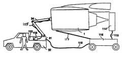
- FIG. 1an exemplary manifold installed in an inlet of an aero engine in accordance with an embodiment the present invention
- FIG. 2illustrates an exemplary washing system according to an embodiment of the present invention comprising a mobile unit.
- a washing systemin accordance with an embodiment of the present invention comprises a washing unit for providing a washing liquid into an engine and a control unit for regulating the washing unit according to desired parameters.
- the washing unitcomprises a manifold, preferably comprising one or more tube-like structures, a pumping system for providing pressurized washing liquid to the manifold, and a control unit for controlling the system's washing procedure according to the particular wash requirements of the particular engine being washed.
- the manifold 10configured in accordance with the present invention is shown mounted on an exemplary aero engine 1 .
- the manifold 10comprises a plurality of tube-like structures 102 , a plurality of nozzles 103 , one each connected to one end of the manifold tubes 102 , a coupling device 104 for coupling the other end(s) of the manifold tubes 102 , and a hose 105 connected to the coupling device 104 for providing an ingress of washing liquid provided by a pumping system (not shown).
- the manifold 10may further comprise an information unit 110 , such as a manifold identification unit 110 , for identifying the type of manifold 10 currently being utilized. This information unit 110 may be attached to any portion of the manifold 10 itself, or to some portion of the coupling device 104 .
- a suitable information unit 110preferably comprises a radio-frequency identification (RFID) chip or tag.
- RFIDradio-frequency identification
- an RFID-chip or tagcan be described as a small microchip that function as transponders, adapted to “listening” for radio signals sent by transceivers (e.g., RFID-reader).
- transceiverse.g., RFID-reader
- RFID chip or tagreceives a certain radio query, it responds by transmitting its unique identification code and other information, back to the transceiver.
- RFID chips or tagsOne benefit of using RFID chips or tags is that they do not require batteries to operate; instead, they are powered by the radio signals transmitted by transceivers.
- any suitable information unit 110may be utilized in accordance with the present invention.
- Other suitable information units 110may comprise, for example, bar code labels, optical readers for obtaining pertinent information from the bar code, radio frequency equipment capable of transmitting and receiving information, etc.
- a corresponding information detector 111is also desirable for reading information provided by the information unit 110 , and for providing this information to a control unit (see FIG. 2 , item 112 ).
- a manifold 10configured for the particular type of engine 1 is releasibly mounted and secured to an inlet 11 of the engine 1 .
- Any suitable securing meanssuch as for example, a strap or similar device may be utilized to secure the manifold 10 in place.
- a hose 105is connected to the coupling device 104 for providing ingress of washing liquid to the engine 1 .
- the washing systemmay also include a collector unit for collecting used washing liquid that emanates from an engine as a result of the washing procedure.
- the control unitmay be responsive to characteristics of the used washing liquid emanating from the engine in order to regulate the washing unit. For example, an analyzing device may be utilized to evaluate the used washing liquid to determine various characteristics, such as types of solids within the used washing liquid. Depending on the results of the evaluation of the used washing liquid, the control unit may then adjust the washing unit to alter the parameters of the washing procedure.
- the exemplary washing systemcomprises the manifold 10 illustrated in FIG. 1 , an optional mobility unit 32 comprising a vehicle connected to an optional used washing liquid collector 116 , a valved-pumping system 113 comprising a tank 31 and a pump (not shown) for regulating the flow of washing liquid, and a control unit 112 for controlling and monitoring the washing process according to the particular engine 1 being washed.
- the pumping system 113is configured to provide pressurized, forty (40) to eighty (80) bar washing liquid to the manifold 10 .
- the exemplary washing system of FIG. 2preferably comprises a collecting device 114 for collecting used washing liquid, a conduit 118 for providing the used washing liquid to a tank 31 for storing washing liquid and treating used washing liquid.
- the information detector 111obtains particular information identifying the engine 1 type from the information unit 110 . This identification is then transmitted to the control unit 112 .
- an exemplary information unit 110may comprise an RFID reader.
- the corresponding information detector 111preferably comprises an RFID reader.
- the control unit 112preferably comprises a programmable logic controller (PLC) capable of being programmed to control and monitor the washing process. It should be understood, however, that the control unit 112 is not limited thereto, and other suitable control units may also be implemented where desired.
- PLCprogrammable logic controller
- the control unit 112is preferably pre-programmed with control data for washing any number of engine types.
- This control datamay include, for example, manifold configurations, washing requirements, washing parameters, etc.
- the control datamay include data relating to particular geographies and expected fouling configurations. With such control data, the control unit 112 can load a specific washing program for the particular engine type. If based on the control data the control unit 112 determines that a combination of several washing liquids is preferred, the washing system of the present invention preferably comprises several tanks containing different types of wash liquids for use in achieving the preferred washing solution.
- control unit 112may be configured to look up data related to solution capabilities of particular washing liquids in order to predict or select an optimized washing process for a particular engine used in a particular mission or geography. This and other information gathered and provided to the control unit 112 is preferably uploaded to an integrated system (not shown) for use by other washing systems.
- control unit 112receives the identity information provided by the information detector 111 , and receives any control data associated with the engine 1 , the control unit 112 is able to determine the washing requirements and preferred washing parameters for the engine 1 being washed. Once these preferred washing parameters are established, the washing system of the present invention is ready to be initiated.
- the control unit 112Upon initiating the preferred washing procedure, the control unit 112 directs the opening of one or more valves of the valved-pumping system 113 until a desired flow of washing fluid is obtained. This fluid flow may be measured, for example, via a flow meter (not shown) and feed back provided to the control unit 112 .
- the washing fluidmay be controlled via, for example, regulating the pressure of the tank (not shown) in which the washing fluid is stored.
- the control unit 112is configured to regulate such pressure.
- the control unit 112is also configured to regulate a washing time for the particular engine being washed. In this manner, the control unit 112 may shut down the valve in order to shut down the pumping system 113 , once the preferred washing time has been reached.
- control unit 112is further configured (or programmed) to measure and collect information regarding a number of parameters and functions in connection with an engine washing process.
- control unit 112may be configured to process temperature data, say from a temperature gauge (not shown), in order to delay initiating a washing procedure until the washing fluid has reached a predetermined washing temperature.
- control unit 112may comprise an optional operator interface (not shown) capable of displaying different control and process information to a user.
- the optional mobile used fluid collector 116is preferably positioned under the engine 1 for use in collecting used washing liquid and any contaminants that exit the engine 1 as a result of a washing process.
- An exemplary fluid collectoris disclosed in International Publication No. WO 05121509 and corresponding U.S. Published Patent Application No. 2006/0081521, the entire contents of which are incorporated herein by reference. Although this used-fluid collector 116 is shown having wheels (for mobility), it should be understood that the used fluid collector 116 of the present invention is not necessarily required to be mobile.
- An exemplary collection device 114is described in International Publication No. WO 05120953, the entire contents of which are incorporated herein by reference.
- the collection device 114may be at spaced separation from the engine 1 , such as shown herein, or alternatively in contact with any part of the engine 1 , such as the engine outlet.
- a conduitmay be utilized between the engine and the collection device.
- a conduitmay be utilized having an opening at one end sized so as to be at least as large as the diameter of the engine outlet, and then in use positioned adjacent to or in contact with the engine, so as to capture the used wash liquid and engine contaminants emanating from the engine outlet.
- the conduitmay be in the form of a mist eliminator, for separating air from liquid, such as by allowing the air to escape out through openings or valves in the conduit.
- the collected waste liquid and contaminantsmay enter a tank (not shown) in the used fluid collector 116 via, for example, a conduit 115 .
- the used washing liquidmay then be pumped via, for example, a conduit 118 to a tank (not shown) in the washing unit 31 located on the mobility unit 32 .
- the washing unit 31is preferably configured to treat the used washing fluid by separating any fouling material from the used washing liquid via an appropriate liquid treatment process.
- This liquid treatment processmay comprise the use of devices such as filters, centrifuges, separators, and the like. Once the used liquid is treated, the liquid may be reused to wash a subsequent engine, or alternatively, it may simply be disposed.
- the control unit 112is further configured to analyze used washing liquid collected by the fluid collector 116 .
- a Total Dissolved Solidsmay be measured by a measuring means arranged, for example, in the fluid collector 116 .
- TDSis measured by measuring the conductivity of used washing liquid. Based on these measurements, the types of solid(s) included in the used liquid may be determined. Measuring means such as sensors, for example, may be used to measure TDS.
- the washing proceduree.g., the wash time, wash temperature, washing fluids, etc.
Landscapes
- Engineering & Computer Science (AREA)
- Mechanical Engineering (AREA)
- General Engineering & Computer Science (AREA)
- Chemical & Material Sciences (AREA)
- Combustion & Propulsion (AREA)
- Cleaning By Liquid Or Steam (AREA)
- Structures Of Non-Positive Displacement Pumps (AREA)
- Control Of Positive-Displacement Pumps (AREA)
Abstract
Description
Claims (16)
Priority Applications (14)
| Application Number | Priority Date | Filing Date | Title |
|---|---|---|---|
| US11/938,479US8197609B2 (en) | 2006-11-28 | 2007-11-12 | Automated detection and control system and method for high pressure water wash application and collection applied to aero compressor washing |
| EP10000277AEP2243562B1 (en) | 2006-11-28 | 2007-11-16 | Automated detection and control system and method for high pressure water wash application and collection applied to aero compressor washing |
| EP07022332.6AEP1927408B1 (en) | 2006-11-28 | 2007-11-16 | Automated detection and control system and method for high pressure water wash application and collection applied to aero compressor washing |
| DK10000277.3TDK2243562T3 (en) | 2006-11-28 | 2007-11-16 | Automated detection and control system and method for high pressure water washing application and collection used for air compressor washing |
| SG200717971-6ASG143197A1 (en) | 2006-11-28 | 2007-11-22 | Automated detection and control system and method for high pressure water wash application and collection applied to aero compressor washing |
| SG2011087897ASG177137A1 (en) | 2006-11-28 | 2007-11-22 | Automated detection and control system and method for high pressure water wash application and collection applied to aero compressor washing |
| CN2012100358239ACN102644487A (en) | 2006-11-28 | 2007-11-23 | Washing system and method for washing aviation compressor |
| CN2007101877472ACN101191426B (en) | 2006-11-28 | 2007-11-23 | Cleaning systems for cleaning aircraft compressors |
| JP2007306115AJP4895306B2 (en) | 2006-11-28 | 2007-11-27 | Automatic detection and control system and method for high pressure water cleaning application and collection applied to aircraft compressor cleaning |
| KR1020070121658AKR100940627B1 (en) | 2006-11-28 | 2007-11-27 | Automatic detection and control system and method for applying and collecting high pressure water used for aero compressor cleaning |
| RU2007144114/06ARU2373411C2 (en) | 2006-11-28 | 2007-11-27 | Turbine engine flushing system, used liquid collection system, engine flushing and used liquid collection system and method of engine flushing |
| TW096145214ATWI360444B (en) | 2006-11-28 | 2007-11-28 | Automated detection and control system and method |
| JP2011156427AJP5354400B2 (en) | 2006-11-28 | 2011-07-15 | Automatic detection and control system and method for high pressure water cleaning application and collection applied to aircraft compressor cleaning |
| US13/347,017US9162262B2 (en) | 2006-11-28 | 2012-01-10 | Automated detection and control system and method for high pressure water wash application and collection applied to aero compressor washing |
Applications Claiming Priority (2)
| Application Number | Priority Date | Filing Date | Title |
|---|---|---|---|
| US86140106P | 2006-11-28 | 2006-11-28 | |
| US11/938,479US8197609B2 (en) | 2006-11-28 | 2007-11-12 | Automated detection and control system and method for high pressure water wash application and collection applied to aero compressor washing |
Related Child Applications (1)
| Application Number | Title | Priority Date | Filing Date |
|---|---|---|---|
| US13/347,017DivisionUS9162262B2 (en) | 2006-11-28 | 2012-01-10 | Automated detection and control system and method for high pressure water wash application and collection applied to aero compressor washing |
Publications (2)
| Publication Number | Publication Date |
|---|---|
| US20080178909A1 US20080178909A1 (en) | 2008-07-31 |
| US8197609B2true US8197609B2 (en) | 2012-06-12 |
Family
ID=39027562
Family Applications (2)
| Application Number | Title | Priority Date | Filing Date |
|---|---|---|---|
| US11/938,479Active2031-01-23US8197609B2 (en) | 2006-11-28 | 2007-11-12 | Automated detection and control system and method for high pressure water wash application and collection applied to aero compressor washing |
| US13/347,017Active2028-07-14US9162262B2 (en) | 2006-11-28 | 2012-01-10 | Automated detection and control system and method for high pressure water wash application and collection applied to aero compressor washing |
Family Applications After (1)
| Application Number | Title | Priority Date | Filing Date |
|---|---|---|---|
| US13/347,017Active2028-07-14US9162262B2 (en) | 2006-11-28 | 2012-01-10 | Automated detection and control system and method for high pressure water wash application and collection applied to aero compressor washing |
Country Status (9)
| Country | Link |
|---|---|
| US (2) | US8197609B2 (en) |
| EP (2) | EP2243562B1 (en) |
| JP (2) | JP4895306B2 (en) |
| KR (1) | KR100940627B1 (en) |
| CN (2) | CN101191426B (en) |
| DK (1) | DK2243562T3 (en) |
| RU (1) | RU2373411C2 (en) |
| SG (2) | SG143197A1 (en) |
| TW (1) | TWI360444B (en) |
Cited By (11)
| Publication number | Priority date | Publication date | Assignee | Title |
|---|---|---|---|---|
| US20120153032A1 (en)* | 2009-07-16 | 2012-06-21 | Elo Svanebjerg | Dynamic De-Icing Distance |
| US20140000717A1 (en)* | 2012-06-27 | 2014-01-02 | United Technologies Corporation | Engine wash apparatus and method |
| US9470105B2 (en) | 2013-11-21 | 2016-10-18 | General Electric Company | Automated water wash system for a gas turbine engine |
| US9932895B2 (en) | 2013-10-10 | 2018-04-03 | Ecoservices, Llc | Radial passage engine wash manifold |
| US20180306055A1 (en)* | 2015-05-29 | 2018-10-25 | Lufthansa Technik Ag | Method and device for cleaning a jet engine |
| US10364699B2 (en) | 2013-10-02 | 2019-07-30 | Aerocore Technologies Llc | Cleaning method for jet engine |
| US10428683B2 (en) | 2016-01-05 | 2019-10-01 | General Electric Company | Abrasive gel detergent for cleaning gas turbine engine components |
| US10807738B2 (en) | 2016-12-01 | 2020-10-20 | General Electric Company | Maintenance operation analytics |
| US10906670B2 (en) | 2016-06-29 | 2021-02-02 | General Electric Company | Methods for effluent based condition assessment |
| US11371385B2 (en) | 2018-04-19 | 2022-06-28 | General Electric Company | Machine foam cleaning system with integrated sensing |
| US11643946B2 (en) | 2013-10-02 | 2023-05-09 | Aerocore Technologies Llc | Cleaning method for jet engine |
Families Citing this family (42)
| Publication number | Priority date | Publication date | Assignee | Title |
|---|---|---|---|---|
| CN1788143B (en)* | 2004-06-14 | 2011-07-06 | 燃气涡轮效率股份有限公司 | System and apparatus for collecting and treating wastewater from engine cleaning |
| US8524010B2 (en)* | 2007-03-07 | 2013-09-03 | Ecoservices, Llc | Transportable integrated wash unit |
| US8342793B2 (en)* | 2007-08-22 | 2013-01-01 | Cleveland Electric Laboratories | Active surge control |
| US8277647B2 (en) | 2007-12-19 | 2012-10-02 | United Technologies Corporation | Effluent collection unit for engine washing |
| DE102008009221A1 (en)* | 2008-02-06 | 2009-08-13 | Alfred Kärcher Gmbh & Co. Kg | System for storing and dispensing liquid cleaning additive for high-pressure cleaning device |
| DE102008019892A1 (en)* | 2008-04-21 | 2009-10-29 | Mtu Aero Engines Gmbh | Method for cleaning an aircraft engine |
| US20100102835A1 (en)* | 2008-10-27 | 2010-04-29 | General Electric Company | Method and system for detecting a corrosive deposit in a compressor |
| US9080460B2 (en) | 2009-03-30 | 2015-07-14 | Ecoservices, Llc | Turbine cleaning system |
| US20100242994A1 (en)* | 2009-03-30 | 2010-09-30 | Gas Turbine Efficiency Sweden Ab | Device and method for collecting waste water from turbine engine washing |
| DE102009033944A1 (en)* | 2009-07-14 | 2011-01-20 | Alfred Kärcher Gmbh & Co. Kg | Cleaning device and method for controlling access to a cleaning device |
| US8448652B2 (en)* | 2010-03-26 | 2013-05-28 | Sunpower Corporation | Solar system cleaning apparatus |
| US8206478B2 (en)* | 2010-04-12 | 2012-06-26 | Pratt & Whitney Line Maintenance Services, Inc. | Portable and modular separator/collector device |
| DE102010042347A1 (en) | 2010-10-12 | 2012-04-12 | Alfred Kärcher Gmbh & Co. Kg | Method for operating a cleaning device and cleaning device for carrying out the method |
| US9631511B2 (en)* | 2012-06-27 | 2017-04-25 | Ecoservices, Llc | Engine wash apparatus and method |
| US9234441B2 (en)* | 2013-03-11 | 2016-01-12 | Pratt & Whitney Canada Corp. | Method of immobilizing low pressure spool and locking tool therefore |
| US9500098B2 (en)* | 2013-03-13 | 2016-11-22 | Ecoservices, Llc | Rear mounted wash manifold and process |
| US9212565B2 (en) | 2013-03-13 | 2015-12-15 | Ecoservices, Llc | Rear mounted wash manifold retention system |
| CN105074137B (en)* | 2013-03-15 | 2017-05-10 | 生态服务股份有限公司 | engine washout collector |
| CN103277148A (en)* | 2013-06-05 | 2013-09-04 | 中国南方航空工业(集团)有限公司 | Flushing device and cleaning method of turbine engine |
| DE102013224639A1 (en)* | 2013-11-29 | 2015-06-03 | Lufthansa Technik Ag | Method and device for cleaning a jet engine |
| ITMI20132042A1 (en) | 2013-12-06 | 2015-06-07 | Nuovo Pignone Srl | METHODS FOR WASHING MOTORS WITH GAS TURBINES AND GAS TURBINE ENGINES |
| US9926517B2 (en) | 2013-12-09 | 2018-03-27 | General Electric Company | Cleaning solution and methods of cleaning a turbine engine |
| JP2016061261A (en)* | 2014-09-19 | 2016-04-25 | 三菱重工業株式会社 | Centrifugal compressor |
| BR102016021259B1 (en) | 2015-10-05 | 2022-06-14 | General Electric Company | METHOD AND SOLUTIONS FOR CLEANING A TURBINE ENGINE AND REAGENT COMPOSITION |
| CN106914439B (en)* | 2015-12-28 | 2021-01-05 | 苏州宝时得电动工具有限公司 | Pressure cleaning machine |
| EP3398695A4 (en)* | 2015-12-28 | 2019-10-16 | Positec Power Tools (Suzhou) Co., Ltd | HIGH PRESSURE CLEANER AND METHOD FOR IDENTIFYING A CORRESPONDING SPRAY RAMP |
| CN105457937B (en)* | 2015-12-29 | 2017-12-12 | 中国航空工业集团公司沈阳发动机设计研究所 | A kind of cleaning device of gas turbine runner elements |
| BE1024315B1 (en)* | 2016-06-28 | 2018-01-30 | Safran Aero Boosters Sa | Propulsion system for aircraft |
| EP3504011B1 (en)* | 2016-09-30 | 2024-10-30 | General Electric Company | Water wash system and method for washing a gas turbine engine |
| CA3045162A1 (en) | 2016-11-28 | 2018-06-07 | Candu Energy Inc. | System and method of cleaning a heat exchanger |
| US10534359B2 (en)* | 2017-01-10 | 2020-01-14 | Honeywell International Inc. | Aircraft management systems and methods for ECS predictive maintenance |
| CN107377462A (en)* | 2017-07-19 | 2017-11-24 | 中国民航大学 | Mobile aviation engine cleans water car-washing in the wing |
| CN107499531B (en)* | 2017-08-01 | 2019-06-21 | 春秋航空技术发展江苏有限公司 | A kind of aero-engine is in wing cleaning machine |
| TWI632091B (en)* | 2017-08-18 | 2018-08-11 | 國家中山科學研究院 | Motorized anti-corrosion cleaning system |
| DE102018119092A1 (en)* | 2018-08-06 | 2020-02-06 | Lufthansa Technik Ag | Device and method for cleaning the core engine of a jet engine |
| RU2706383C1 (en)* | 2018-10-22 | 2019-11-18 | Общество с ограниченной ответственностью "Искра-Нефтегаз Компрессор" | Device for centrifugal compressor flow part washing |
| CN109465224A (en)* | 2018-11-19 | 2019-03-15 | 佛山市顺德区美的洗涤电器制造有限公司 | Range hood |
| CN111659657B (en)* | 2019-03-07 | 2022-03-22 | 苏州宝时得电动工具有限公司 | High pressure cleaning machine |
| GB201906541D0 (en) | 2019-05-09 | 2019-06-26 | Rolls Royce Plc | Washing tool, washing system and a method of washing |
| CN112412630B (en)* | 2020-12-07 | 2024-07-02 | 华北电力科学研究院有限责任公司 | Gas turbine compressor water washing system and control method thereof |
| RU2752442C1 (en)* | 2020-12-29 | 2021-07-28 | Общество с ограниченной ответственностью «ЭНЕРГЕТИЧЕСКИЕ СИСТЕМЫ» | Unit for pumping and cooling associated petroleum gas, device and method for flushing it |
| CN215444164U (en)* | 2021-01-29 | 2022-01-07 | 烟台杰瑞石油装备技术有限公司 | Turbine engine washing system |
Citations (32)
| Publication number | Priority date | Publication date | Assignee | Title |
|---|---|---|---|---|
| DE2701823A1 (en) | 1976-01-29 | 1977-08-04 | Laszlo Arato | Programmed washing unit for aircraft - .HAS SPRAY NOZZLES MOUNTED ON VEHICLE WITH POSITIONS CONTROLLED DEPENDENT ON LASER SENSORS |
| US4196020A (en)* | 1978-11-15 | 1980-04-01 | Avco Corporation | Removable wash spray apparatus for gas turbine engine |
| JPS6313834A (en) | 1986-07-05 | 1988-01-21 | Honda Motor Co Ltd | Vehicle clutch control method |
| US5011540A (en) | 1986-12-24 | 1991-04-30 | Mcdermott Peter | Method and apparatus for cleaning a gas turbine engine |
| SU1755965A1 (en) | 1989-08-07 | 1992-08-23 | Киевский Институт Инженеров Гражданской Авиации Им.60-Летия Ссср | Method of washing flow-through section of gas-turbine engine |
| SU1767205A1 (en) | 1990-06-27 | 1992-10-07 | Научно-производственное объединение "Сатурн" им.А.М.Люльки | Method of washing gas-air channel of gas-turbine engine |
| RU2000458C1 (en) | 1990-10-29 | 1993-09-07 | Государственный научно-исследовательский институт гражданской авиации | Apparatus for washing gas-air flow duct of engine |
| US5273395A (en) | 1986-12-24 | 1993-12-28 | Rochem Technical Services Holding Ag | Apparatus for cleaning a gas turbine engine |
| JPH0658172A (en) | 1992-08-03 | 1994-03-01 | Kobe Steel Ltd | Gas turbine compressor washing device |
| US5318254A (en) | 1991-06-28 | 1994-06-07 | Conceptual Solutions, Inc. | Aircraft maintenance robot |
| EP0628477A1 (en) | 1993-06-11 | 1994-12-14 | Spar Aerospace Limited | Robot arm and method of its use |
| DE9420362U1 (en) | 1994-12-20 | 1995-03-30 | Hanrath, Rita, 52525 Heinsberg | Detergent catcher for compressor cleaning of aircraft engines |
| JPH08128333A (en) | 1994-10-31 | 1996-05-21 | Kawasaki Heavy Ind Ltd | Automatic cleaning equipment for gas turbine compressors |
| KR19980017193A (en) | 1996-08-30 | 1998-06-05 | 이영리 | The antibacterial water purifier and the metal ion water produced in this water purifier |
| US5899217A (en) | 1998-02-10 | 1999-05-04 | Testman, Jr.; Frank L. | Engine wash recovery system |
| EP0933502A2 (en) | 1998-01-30 | 1999-08-04 | Speciality Chemical Holdings Limited | Wash system for gas turbine compressors |
| US5954070A (en) | 1998-07-31 | 1999-09-21 | Northrop Grumman Corporation | Fluid application and concentration monitoring system |
| US20010049846A1 (en)* | 2000-06-12 | 2001-12-13 | Guzzi Brian Daniel | Method and system for optimizing performance of consumer appliances |
| US20020001255A1 (en) | 2000-04-05 | 2002-01-03 | Flood Jeffrey D. | Portable concrete plant |
| US20020129837A1 (en)* | 2001-03-14 | 2002-09-19 | Ruiz R. Dwane | Forced mist cleaning of combustion turbines |
| US6478033B1 (en)* | 2000-05-26 | 2002-11-12 | Hydrochem Industrial Services, Inc. | Methods for foam cleaning combustion turbines |
| US6491048B1 (en)* | 2000-05-26 | 2002-12-10 | Hydrochem Industrial Services, Inc. | Manifold for use in cleaning combustion turbines |
| US20030209256A1 (en) | 2002-05-13 | 2003-11-13 | Shahin Tadayon | Jet wet suit cover system for gaspath cleaning |
| US6675437B1 (en) | 1999-12-15 | 2004-01-13 | Shawn L. York | Portable high-temperature, high-pressure washing plant |
| US6932093B2 (en)* | 2003-02-24 | 2005-08-23 | General Electric Company | Methods and apparatus for washing gas turbine engine combustors |
| WO2005077554A1 (en) | 2004-02-16 | 2005-08-25 | Gas Turbine Efficiency Ab | Method and apparatus for cleaning a turbofan gas turbine engine |
| US20050199270A1 (en)* | 2004-03-12 | 2005-09-15 | John Watt | Mobile flushing unit and process |
| WO2005121509A1 (en) | 2004-06-14 | 2005-12-22 | Gas Turbine Efficiency Ab | System and devices for collecting and treating waste water from engine washing |
| US20070059159A1 (en)* | 2005-09-13 | 2007-03-15 | Gas Turbine Efficiency Ab | System and method for augmenting power output from a gas turbine engine |
| KR20070042852A (en) | 2005-05-20 | 2007-04-24 | 가스 터빈 이피션시 에이비 | Systems and devices for collecting and treating wastewater from engine cleaning |
| WO2007102738A1 (en) | 2006-03-08 | 2007-09-13 | Dynatrend As | A method and device for cleaning an axial compressor |
| US20090050183A1 (en) | 2007-08-22 | 2009-02-26 | Rice Robert M | Integrated wash unit for a turbine engine |
Family Cites Families (6)
| Publication number | Priority date | Publication date | Assignee | Title |
|---|---|---|---|---|
| GB2062109A (en) | 1979-10-31 | 1981-05-20 | Wallop Ind Ltd | Rocket motor |
| JPS63131834A (en)* | 1986-11-19 | 1988-06-03 | Toshiba Eng & Constr Co Ltd | Device for detecting pollution in air compressor and gas turbine and washing device using said detecting device |
| JPH0313834A (en) | 1989-06-12 | 1991-01-22 | Fujii Gokin Seisakusho:Kk | Gas-cock inspecting method |
| US6553768B1 (en) | 2000-11-01 | 2003-04-29 | General Electric Company | Combined water-wash and wet-compression system for a gas turbine compressor and related method |
| JP2005147034A (en)* | 2003-11-18 | 2005-06-09 | Mitsubishi Heavy Ind Ltd | Air filter for gas turbine, and washing method and washing system for the same, and service life prediction testing method for the same |
| US8764910B2 (en)* | 2004-09-17 | 2014-07-01 | Ness Lakdawala | Method and a washing system for washing turbines |
- 2007
- 2007-11-12USUS11/938,479patent/US8197609B2/enactiveActive
- 2007-11-16EPEP10000277Apatent/EP2243562B1/enactiveActive
- 2007-11-16EPEP07022332.6Apatent/EP1927408B1/enactiveActive
- 2007-11-16DKDK10000277.3Tpatent/DK2243562T3/enactive
- 2007-11-22SGSG200717971-6Apatent/SG143197A1/enunknown
- 2007-11-22SGSG2011087897Apatent/SG177137A1/enunknown
- 2007-11-23CNCN2007101877472Apatent/CN101191426B/ennot_activeExpired - Fee Related
- 2007-11-23CNCN2012100358239Apatent/CN102644487A/enactivePending
- 2007-11-27RURU2007144114/06Apatent/RU2373411C2/ennot_activeIP Right Cessation
- 2007-11-27JPJP2007306115Apatent/JP4895306B2/ennot_activeExpired - Fee Related
- 2007-11-27KRKR1020070121658Apatent/KR100940627B1/ennot_activeExpired - Fee Related
- 2007-11-28TWTW096145214Apatent/TWI360444B/ennot_activeIP Right Cessation
- 2011
- 2011-07-15JPJP2011156427Apatent/JP5354400B2/ennot_activeExpired - Fee Related
- 2012
- 2012-01-10USUS13/347,017patent/US9162262B2/enactiveActive
Patent Citations (36)
| Publication number | Priority date | Publication date | Assignee | Title |
|---|---|---|---|---|
| DE2701823A1 (en) | 1976-01-29 | 1977-08-04 | Laszlo Arato | Programmed washing unit for aircraft - .HAS SPRAY NOZZLES MOUNTED ON VEHICLE WITH POSITIONS CONTROLLED DEPENDENT ON LASER SENSORS |
| US4196020A (en)* | 1978-11-15 | 1980-04-01 | Avco Corporation | Removable wash spray apparatus for gas turbine engine |
| JPS6313834A (en) | 1986-07-05 | 1988-01-21 | Honda Motor Co Ltd | Vehicle clutch control method |
| US5011540A (en) | 1986-12-24 | 1991-04-30 | Mcdermott Peter | Method and apparatus for cleaning a gas turbine engine |
| US5273395A (en) | 1986-12-24 | 1993-12-28 | Rochem Technical Services Holding Ag | Apparatus for cleaning a gas turbine engine |
| SU1755965A1 (en) | 1989-08-07 | 1992-08-23 | Киевский Институт Инженеров Гражданской Авиации Им.60-Летия Ссср | Method of washing flow-through section of gas-turbine engine |
| SU1767205A1 (en) | 1990-06-27 | 1992-10-07 | Научно-производственное объединение "Сатурн" им.А.М.Люльки | Method of washing gas-air channel of gas-turbine engine |
| RU2000458C1 (en) | 1990-10-29 | 1993-09-07 | Государственный научно-исследовательский институт гражданской авиации | Apparatus for washing gas-air flow duct of engine |
| US5318254A (en) | 1991-06-28 | 1994-06-07 | Conceptual Solutions, Inc. | Aircraft maintenance robot |
| JPH0658172A (en) | 1992-08-03 | 1994-03-01 | Kobe Steel Ltd | Gas turbine compressor washing device |
| EP0628477A1 (en) | 1993-06-11 | 1994-12-14 | Spar Aerospace Limited | Robot arm and method of its use |
| JPH08128333A (en) | 1994-10-31 | 1996-05-21 | Kawasaki Heavy Ind Ltd | Automatic cleaning equipment for gas turbine compressors |
| DE9420362U1 (en) | 1994-12-20 | 1995-03-30 | Hanrath, Rita, 52525 Heinsberg | Detergent catcher for compressor cleaning of aircraft engines |
| KR19980017193A (en) | 1996-08-30 | 1998-06-05 | 이영리 | The antibacterial water purifier and the metal ion water produced in this water purifier |
| EP0933502A2 (en) | 1998-01-30 | 1999-08-04 | Speciality Chemical Holdings Limited | Wash system for gas turbine compressors |
| US6073637A (en) | 1998-01-30 | 2000-06-13 | Speciality Chemical Holdings Limited | Cleaning method and apparatus |
| US5899217A (en) | 1998-02-10 | 1999-05-04 | Testman, Jr.; Frank L. | Engine wash recovery system |
| US5954070A (en) | 1998-07-31 | 1999-09-21 | Northrop Grumman Corporation | Fluid application and concentration monitoring system |
| US6675437B1 (en) | 1999-12-15 | 2004-01-13 | Shawn L. York | Portable high-temperature, high-pressure washing plant |
| US20020001255A1 (en) | 2000-04-05 | 2002-01-03 | Flood Jeffrey D. | Portable concrete plant |
| US6491048B1 (en)* | 2000-05-26 | 2002-12-10 | Hydrochem Industrial Services, Inc. | Manifold for use in cleaning combustion turbines |
| US6478033B1 (en)* | 2000-05-26 | 2002-11-12 | Hydrochem Industrial Services, Inc. | Methods for foam cleaning combustion turbines |
| US20010049846A1 (en)* | 2000-06-12 | 2001-12-13 | Guzzi Brian Daniel | Method and system for optimizing performance of consumer appliances |
| US20020129837A1 (en)* | 2001-03-14 | 2002-09-19 | Ruiz R. Dwane | Forced mist cleaning of combustion turbines |
| US20030209256A1 (en) | 2002-05-13 | 2003-11-13 | Shahin Tadayon | Jet wet suit cover system for gaspath cleaning |
| US6932093B2 (en)* | 2003-02-24 | 2005-08-23 | General Electric Company | Methods and apparatus for washing gas turbine engine combustors |
| WO2005077554A1 (en) | 2004-02-16 | 2005-08-25 | Gas Turbine Efficiency Ab | Method and apparatus for cleaning a turbofan gas turbine engine |
| US20060048796A1 (en) | 2004-02-16 | 2006-03-09 | Peter Asplund | Method and apparatus for cleaning a turbofan gas turbine engine |
| US20050199270A1 (en)* | 2004-03-12 | 2005-09-15 | John Watt | Mobile flushing unit and process |
| WO2005120953A1 (en) | 2004-06-14 | 2005-12-22 | Gas Turbine Efficiency Ab | System for washing an aero gas turbine engine |
| WO2005121509A1 (en) | 2004-06-14 | 2005-12-22 | Gas Turbine Efficiency Ab | System and devices for collecting and treating waste water from engine washing |
| US20060081521A1 (en) | 2004-06-14 | 2006-04-20 | Carl-Johan Hjerpe | System and devices for collecting and treating waste water from engine washing |
| KR20070042852A (en) | 2005-05-20 | 2007-04-24 | 가스 터빈 이피션시 에이비 | Systems and devices for collecting and treating wastewater from engine cleaning |
| US20070059159A1 (en)* | 2005-09-13 | 2007-03-15 | Gas Turbine Efficiency Ab | System and method for augmenting power output from a gas turbine engine |
| WO2007102738A1 (en) | 2006-03-08 | 2007-09-13 | Dynatrend As | A method and device for cleaning an axial compressor |
| US20090050183A1 (en) | 2007-08-22 | 2009-02-26 | Rice Robert M | Integrated wash unit for a turbine engine |
Non-Patent Citations (4)
| Title |
|---|
| English Abstract of SU 1755965 to Chumak et al., Aug. 1992.* |
| English Abstract of SU 1767205 to Atlas et al., Oct. 1992.* |
| Taiwan Office Action, mailed Mar. 21, 2011. |
| Translation of Decision of granting a patent for invention, RU2373411, granted Nov. 20, 2009. |
Cited By (15)
| Publication number | Priority date | Publication date | Assignee | Title |
|---|---|---|---|---|
| US8967542B2 (en)* | 2009-07-16 | 2015-03-03 | Vestergaard Company A/S | Dynamic de-icing distance |
| US20120153032A1 (en)* | 2009-07-16 | 2012-06-21 | Elo Svanebjerg | Dynamic De-Icing Distance |
| US20140000717A1 (en)* | 2012-06-27 | 2014-01-02 | United Technologies Corporation | Engine wash apparatus and method |
| US9821352B2 (en)* | 2012-06-27 | 2017-11-21 | Ecoservices, Llc | Engine wash apparatus and method |
| US11643946B2 (en) | 2013-10-02 | 2023-05-09 | Aerocore Technologies Llc | Cleaning method for jet engine |
| US10364699B2 (en) | 2013-10-02 | 2019-07-30 | Aerocore Technologies Llc | Cleaning method for jet engine |
| US9932895B2 (en) | 2013-10-10 | 2018-04-03 | Ecoservices, Llc | Radial passage engine wash manifold |
| US9470105B2 (en) | 2013-11-21 | 2016-10-18 | General Electric Company | Automated water wash system for a gas turbine engine |
| US20180306055A1 (en)* | 2015-05-29 | 2018-10-25 | Lufthansa Technik Ag | Method and device for cleaning a jet engine |
| US11215071B2 (en)* | 2015-05-29 | 2022-01-04 | Lufthansa Technik Ag | Method and device for cleaning a jet engine |
| US10428683B2 (en) | 2016-01-05 | 2019-10-01 | General Electric Company | Abrasive gel detergent for cleaning gas turbine engine components |
| US10906670B2 (en) | 2016-06-29 | 2021-02-02 | General Electric Company | Methods for effluent based condition assessment |
| US10807738B2 (en) | 2016-12-01 | 2020-10-20 | General Electric Company | Maintenance operation analytics |
| US11371385B2 (en) | 2018-04-19 | 2022-06-28 | General Electric Company | Machine foam cleaning system with integrated sensing |
| US11952906B2 (en) | 2018-04-19 | 2024-04-09 | General Electric Company | Machine foam cleaning system with integrated sensing |
Also Published As
| Publication number | Publication date |
|---|---|
| JP5354400B2 (en) | 2013-11-27 |
| TWI360444B (en) | 2012-03-21 |
| CN101191426A (en) | 2008-06-04 |
| SG143197A1 (en) | 2008-06-27 |
| EP2243562A1 (en) | 2010-10-27 |
| JP4895306B2 (en) | 2012-03-14 |
| RU2373411C2 (en) | 2009-11-20 |
| US20080178909A1 (en) | 2008-07-31 |
| DK2243562T3 (en) | 2013-05-06 |
| US20120103375A1 (en) | 2012-05-03 |
| EP1927408A2 (en) | 2008-06-04 |
| CN102644487A (en) | 2012-08-22 |
| US20140251392A9 (en) | 2014-09-11 |
| KR100940627B1 (en) | 2010-02-05 |
| US9162262B2 (en) | 2015-10-20 |
| TW200846094A (en) | 2008-12-01 |
| EP1927408A3 (en) | 2009-12-02 |
| EP2243562B1 (en) | 2013-03-27 |
| EP1927408B1 (en) | 2014-12-24 |
| CN101191426B (en) | 2012-12-12 |
| JP2011231773A (en) | 2011-11-17 |
| JP2008169828A (en) | 2008-07-24 |
| KR20080048420A (en) | 2008-06-02 |
| RU2007144114A (en) | 2009-06-10 |
| SG177137A1 (en) | 2012-01-30 |
Similar Documents
| Publication | Publication Date | Title |
|---|---|---|
| US8197609B2 (en) | Automated detection and control system and method for high pressure water wash application and collection applied to aero compressor washing | |
| AU2004320619B2 (en) | System and devices for collecting and treating waste water from engine washing | |
| RU2391526C1 (en) | Blow-off drain valve for control of fluid medium flow, flushing system, detecting device of flushing cycle and method of performing flushing cycle | |
| CA2611732C (en) | Automated detection and control system and method for high pressure water wash application and collection applied to aero compressor washing | |
| HK1173760A (en) | System and method for washing aero compressor | |
| CA2763088C (en) | System and devices for collecting and treating waste water from engine washing | |
| CN210372861U (en) | Transfer device for liquid ammonia transfer | |
| AU2012258473B2 (en) | System and devices for collecting and treating waste water from engine washing | |
| KR20100093114A (en) | System for washing an aero gas turbine engine |
Legal Events
| Date | Code | Title | Description |
|---|---|---|---|
| AS | Assignment | Owner name:GAS TURBINE EFFICIENCY SWEDEN AB, SWEDEN Free format text:ASSIGNMENT OF ASSIGNORS INTEREST;ASSIGNORS:ALVESTIG, PER G.;NORDLUND, SEBASTIAN;REEL/FRAME:020286/0124 Effective date:20071220 | |
| AS | Assignment | Owner name:PRATT & WHITNEY LINE MAINTENANCE SERVICES, INC., C Free format text:ASSIGNMENT OF ASSIGNORS INTEREST;ASSIGNORS:GAS TURBINE EFFICIENCY AB;GAS TURBINE EFFICIENCY SWEDEN AS;REEL/FRAME:025859/0110 Effective date:20110111 | |
| STCF | Information on status: patent grant | Free format text:PATENTED CASE | |
| CC | Certificate of correction | ||
| AS | Assignment | Owner name:ECOSERVICES, LLC, CONNECTICUT Free format text:ASSIGNMENT OF ASSIGNORS INTEREST;ASSIGNOR:PRATT & WHITNEY LINE MAINTENANCE SERVICES, INC.;REEL/FRAME:030238/0298 Effective date:20130311 | |
| FPAY | Fee payment | Year of fee payment:4 | |
| AS | Assignment | Owner name:PRATT & WHITNEY LINE MAINTENANCE SERVICES, INC., C Free format text:CORRECTIVE ASSIGNMENT TO CORRECT THE THE NAME OF THE 2ND ASSIGNOR PREVIOUSLY RECORDED AT REEL: 025859 FRAME: 0110. ASSIGNOR(S) HEREBY CONFIRMS THE ASSIGNMENT;ASSIGNORS:GAS TURBINE EFFICIENCY AB;GAS TURBINE EFFICIENCY SWEDEN AB;REEL/FRAME:044167/0036 Effective date:20110118 | |
| MAFP | Maintenance fee payment | Free format text:PAYMENT OF MAINTENANCE FEE, 8TH YEAR, LARGE ENTITY (ORIGINAL EVENT CODE: M1552); ENTITY STATUS OF PATENT OWNER: LARGE ENTITY Year of fee payment:8 | |
| MAFP | Maintenance fee payment | Free format text:PAYMENT OF MAINTENANCE FEE, 12TH YEAR, LARGE ENTITY (ORIGINAL EVENT CODE: M1553); ENTITY STATUS OF PATENT OWNER: LARGE ENTITY Year of fee payment:12 |