US8197510B2 - Suturing device and method - Google Patents
Suturing device and methodDownload PDFInfo
- Publication number
- US8197510B2 US8197510B2US11/653,103US65310307AUS8197510B2US 8197510 B2US8197510 B2US 8197510B2US 65310307 AUS65310307 AUS 65310307AUS 8197510 B2US8197510 B2US 8197510B2
- Authority
- US
- United States
- Prior art keywords
- suture
- arms
- needle
- needles
- arm
- Prior art date
- Legal status (The legal status is an assumption and is not a legal conclusion. Google has not performed a legal analysis and makes no representation as to the accuracy of the status listed.)
- Expired - Fee Related, expires
Links
- 238000000034methodMethods0.000titleclaimsabstractdescription66
- 208000008883Patent Foramen OvaleDiseases0.000claimsdescription16
- 229920004934Dacron®Polymers0.000claimsdescription3
- 239000005020polyethylene terephthalateSubstances0.000claimsdescription3
- 102000008186CollagenHuman genes0.000claims2
- 108010035532CollagenProteins0.000claims2
- 229920001436collagenPolymers0.000claims2
- 210000001519tissueAnatomy0.000description79
- 210000001367arteryAnatomy0.000description29
- 210000004204blood vesselAnatomy0.000description19
- 238000003780insertionMethods0.000description17
- 230000037431insertionEffects0.000description17
- 239000000463materialSubstances0.000description16
- 230000000149penetrating effectEffects0.000description16
- 230000033001locomotionEffects0.000description15
- 210000000689upper legAnatomy0.000description15
- 230000007246mechanismEffects0.000description13
- 210000003813thumbAnatomy0.000description13
- 230000009471actionEffects0.000description12
- 239000008280bloodSubstances0.000description11
- 210000004369bloodAnatomy0.000description11
- 210000003811fingerAnatomy0.000description11
- 230000008901benefitEffects0.000description9
- 208000025339heart septal defectDiseases0.000description9
- 230000006378damageEffects0.000description8
- 208000007536ThrombosisDiseases0.000description7
- 230000017531blood circulationEffects0.000description7
- 230000006870functionEffects0.000description7
- 238000005452bendingMethods0.000description6
- 238000001125extrusionMethods0.000description6
- 210000001105femoral arteryAnatomy0.000description6
- 210000000056organAnatomy0.000description6
- 208000035478Interatrial communicationDiseases0.000description5
- 230000004913activationEffects0.000description5
- 208000013914atrial heart septal defectDiseases0.000description5
- 206010003664atrial septal defectDiseases0.000description5
- 230000006835compressionEffects0.000description5
- 238000007906compressionMethods0.000description5
- 239000011324beadSubstances0.000description4
- 230000000994depressogenic effectEffects0.000description4
- 208000014674injuryDiseases0.000description4
- 210000003041ligamentAnatomy0.000description4
- 239000003550markerSubstances0.000description4
- 239000004033plasticSubstances0.000description4
- 229920003023plasticPolymers0.000description4
- 239000003356suture materialSubstances0.000description4
- 229910000639Spring steelInorganic materials0.000description3
- 206010052428WoundDiseases0.000description3
- 229910001220stainless steelInorganic materials0.000description3
- 239000010935stainless steelSubstances0.000description3
- 229920002994synthetic fiberPolymers0.000description3
- XEEYBQQBJWHFJM-UHFFFAOYSA-NIronChemical compound[Fe]XEEYBQQBJWHFJM-UHFFFAOYSA-N0.000description2
- 239000004642PolyimideSubstances0.000description2
- 239000004792ProleneSubstances0.000description2
- 208000027418Wounds and injuryDiseases0.000description2
- 238000002399angioplastyMethods0.000description2
- 238000013459approachMethods0.000description2
- 230000036772blood pressureEffects0.000description2
- 208000028831congenital heart diseaseDiseases0.000description2
- 238000007796conventional methodMethods0.000description2
- 230000007547defectEffects0.000description2
- 229940079593drugDrugs0.000description2
- 239000003814drugSubstances0.000description2
- 238000010438heat treatmentMethods0.000description2
- 238000004519manufacturing processMethods0.000description2
- 239000000155meltSubstances0.000description2
- 208000003278patent ductus arteriosusDiseases0.000description2
- -1polyethylenePolymers0.000description2
- 229920001721polyimidePolymers0.000description2
- 230000002028prematureEffects0.000description2
- 230000008569processEffects0.000description2
- 230000009467reductionEffects0.000description2
- 210000005245right atriumAnatomy0.000description2
- 238000007789sealingMethods0.000description2
- 239000012781shape memory materialSubstances0.000description2
- 239000000725suspensionSubstances0.000description2
- 238000013519translationMethods0.000description2
- 230000008733traumaEffects0.000description2
- 206010063836Atrioventricular septal defectDiseases0.000description1
- 206010048475Bladder prolapseDiseases0.000description1
- 208000032170Congenital AbnormalitiesDiseases0.000description1
- 208000007228Endocardial Cushion DefectsDiseases0.000description1
- 208000023281Fallot tetralogyDiseases0.000description1
- 229920000544Gore-TexPolymers0.000description1
- 206010020772HypertensionDiseases0.000description1
- 239000004677NylonSubstances0.000description1
- 240000007643Phytolacca americanaSpecies0.000description1
- 239000004698PolyethyleneSubstances0.000description1
- FAPWRFPIFSIZLT-UHFFFAOYSA-MSodium chlorideChemical compound[Na+].[Cl-]FAPWRFPIFSIZLT-UHFFFAOYSA-M0.000description1
- 201000003005Tetralogy of FallotDiseases0.000description1
- 206010046814Uterine prolapseDiseases0.000description1
- 230000001154acute effectEffects0.000description1
- 230000003872anastomosisEffects0.000description1
- 238000002583angiographyMethods0.000description1
- 230000000903blocking effectEffects0.000description1
- 210000000988bone and boneAnatomy0.000description1
- 239000003086colorantSubstances0.000description1
- 238000004040coloringMethods0.000description1
- 238000010276constructionMethods0.000description1
- 238000002788crimpingMethods0.000description1
- 230000007423decreaseEffects0.000description1
- 230000000881depressing effectEffects0.000description1
- 238000006073displacement reactionMethods0.000description1
- 230000000694effectsEffects0.000description1
- 230000001747exhibiting effectEffects0.000description1
- 239000012530fluidSubstances0.000description1
- 230000008571general functionEffects0.000description1
- 230000036541healthEffects0.000description1
- 210000005003heart tissueAnatomy0.000description1
- 229910052742ironInorganic materials0.000description1
- 210000004731jugular veinAnatomy0.000description1
- 239000002184metalSubstances0.000description1
- 229910052751metalInorganic materials0.000description1
- 238000012986modificationMethods0.000description1
- 230000004048modificationEffects0.000description1
- 238000012544monitoring processMethods0.000description1
- 210000003205muscleAnatomy0.000description1
- 229920001778nylonPolymers0.000description1
- 230000036407painEffects0.000description1
- 230000035515penetrationEffects0.000description1
- 229920000573polyethylenePolymers0.000description1
- 229920000642polymerPolymers0.000description1
- 229920002635polyurethanePolymers0.000description1
- 239000004814polyurethaneSubstances0.000description1
- 238000003825pressingMethods0.000description1
- 230000008439repair processEffects0.000description1
- 239000012858resilient materialSubstances0.000description1
- 230000004044responseEffects0.000description1
- 230000000717retained effectEffects0.000description1
- 239000000523sampleSubstances0.000description1
- 230000037390scarringEffects0.000description1
- 238000005476solderingMethods0.000description1
- 239000011343solid materialSubstances0.000description1
- 210000001321subclavian veinAnatomy0.000description1
- 229910000811surgical stainless steelInorganic materials0.000description1
- 239000010966surgical stainless steelSubstances0.000description1
- 210000001631vena cava inferiorAnatomy0.000description1
- 210000002620vena cava superiorAnatomy0.000description1
- 230000000007visual effectEffects0.000description1
Images


Classifications
- A—HUMAN NECESSITIES
- A61—MEDICAL OR VETERINARY SCIENCE; HYGIENE
- A61B—DIAGNOSIS; SURGERY; IDENTIFICATION
- A61B17/00—Surgical instruments, devices or methods
- A61B17/0057—Implements for plugging an opening in the wall of a hollow or tubular organ, e.g. for sealing a vessel puncture or closing a cardiac septal defect
- A—HUMAN NECESSITIES
- A61—MEDICAL OR VETERINARY SCIENCE; HYGIENE
- A61B—DIAGNOSIS; SURGERY; IDENTIFICATION
- A61B17/00—Surgical instruments, devices or methods
- A61B17/04—Surgical instruments, devices or methods for suturing wounds; Holders or packages for needles or suture materials
- A61B17/0469—Suturing instruments for use in minimally invasive surgery, e.g. endoscopic surgery
- A—HUMAN NECESSITIES
- A61—MEDICAL OR VETERINARY SCIENCE; HYGIENE
- A61B—DIAGNOSIS; SURGERY; IDENTIFICATION
- A61B17/00—Surgical instruments, devices or methods
- A61B17/04—Surgical instruments, devices or methods for suturing wounds; Holders or packages for needles or suture materials
- A61B17/0482—Needle or suture guides
- A—HUMAN NECESSITIES
- A61—MEDICAL OR VETERINARY SCIENCE; HYGIENE
- A61B—DIAGNOSIS; SURGERY; IDENTIFICATION
- A61B17/00—Surgical instruments, devices or methods
- A61B17/04—Surgical instruments, devices or methods for suturing wounds; Holders or packages for needles or suture materials
- A61B17/06—Needles ; Sutures; Needle-suture combinations; Holders or packages for needles or suture materials
- A61B17/062—Needle manipulators
- A61B17/0625—Needle manipulators the needle being specially adapted to interact with the manipulator, e.g. being ridged to snap fit in a hole of the manipulator
- A—HUMAN NECESSITIES
- A61—MEDICAL OR VETERINARY SCIENCE; HYGIENE
- A61B—DIAGNOSIS; SURGERY; IDENTIFICATION
- A61B17/00—Surgical instruments, devices or methods
- A61B17/04—Surgical instruments, devices or methods for suturing wounds; Holders or packages for needles or suture materials
- A61B17/0491—Sewing machines for surgery
- A—HUMAN NECESSITIES
- A61—MEDICAL OR VETERINARY SCIENCE; HYGIENE
- A61B—DIAGNOSIS; SURGERY; IDENTIFICATION
- A61B17/00—Surgical instruments, devices or methods
- A61B17/04—Surgical instruments, devices or methods for suturing wounds; Holders or packages for needles or suture materials
- A61B17/06—Needles ; Sutures; Needle-suture combinations; Holders or packages for needles or suture materials
- A61B17/06166—Sutures
- A—HUMAN NECESSITIES
- A61—MEDICAL OR VETERINARY SCIENCE; HYGIENE
- A61B—DIAGNOSIS; SURGERY; IDENTIFICATION
- A61B17/00—Surgical instruments, devices or methods
- A61B17/0057—Implements for plugging an opening in the wall of a hollow or tubular organ, e.g. for sealing a vessel puncture or closing a cardiac septal defect
- A61B2017/00637—Implements for plugging an opening in the wall of a hollow or tubular organ, e.g. for sealing a vessel puncture or closing a cardiac septal defect for sealing trocar wounds through abdominal wall
- A—HUMAN NECESSITIES
- A61—MEDICAL OR VETERINARY SCIENCE; HYGIENE
- A61B—DIAGNOSIS; SURGERY; IDENTIFICATION
- A61B17/00—Surgical instruments, devices or methods
- A61B17/0057—Implements for plugging an opening in the wall of a hollow or tubular organ, e.g. for sealing a vessel puncture or closing a cardiac septal defect
- A61B2017/00646—Type of implements
- A61B2017/00659—Type of implements located only on one side of the opening
- A—HUMAN NECESSITIES
- A61—MEDICAL OR VETERINARY SCIENCE; HYGIENE
- A61B—DIAGNOSIS; SURGERY; IDENTIFICATION
- A61B17/00—Surgical instruments, devices or methods
- A61B17/0057—Implements for plugging an opening in the wall of a hollow or tubular organ, e.g. for sealing a vessel puncture or closing a cardiac septal defect
- A61B2017/00646—Type of implements
- A61B2017/00663—Type of implements the implement being a suture
- A—HUMAN NECESSITIES
- A61—MEDICAL OR VETERINARY SCIENCE; HYGIENE
- A61B—DIAGNOSIS; SURGERY; IDENTIFICATION
- A61B17/00—Surgical instruments, devices or methods
- A61B17/0057—Implements for plugging an opening in the wall of a hollow or tubular organ, e.g. for sealing a vessel puncture or closing a cardiac septal defect
- A61B2017/00672—Locating means therefor, e.g. bleed back lumen
- A—HUMAN NECESSITIES
- A61—MEDICAL OR VETERINARY SCIENCE; HYGIENE
- A61B—DIAGNOSIS; SURGERY; IDENTIFICATION
- A61B17/00—Surgical instruments, devices or methods
- A61B2017/00831—Material properties
- A61B2017/00867—Material properties shape memory effect
- A—HUMAN NECESSITIES
- A61—MEDICAL OR VETERINARY SCIENCE; HYGIENE
- A61B—DIAGNOSIS; SURGERY; IDENTIFICATION
- A61B17/00—Surgical instruments, devices or methods
- A61B17/04—Surgical instruments, devices or methods for suturing wounds; Holders or packages for needles or suture materials
- A61B17/0469—Suturing instruments for use in minimally invasive surgery, e.g. endoscopic surgery
- A61B2017/0472—Multiple-needled, e.g. double-needled, instruments
- A—HUMAN NECESSITIES
- A61—MEDICAL OR VETERINARY SCIENCE; HYGIENE
- A61B—DIAGNOSIS; SURGERY; IDENTIFICATION
- A61B17/00—Surgical instruments, devices or methods
- A61B17/04—Surgical instruments, devices or methods for suturing wounds; Holders or packages for needles or suture materials
- A61B17/06—Needles ; Sutures; Needle-suture combinations; Holders or packages for needles or suture materials
- A61B17/06004—Means for attaching suture to needle
- A61B2017/06042—Means for attaching suture to needle located close to needle tip
- A—HUMAN NECESSITIES
- A61—MEDICAL OR VETERINARY SCIENCE; HYGIENE
- A61B—DIAGNOSIS; SURGERY; IDENTIFICATION
- A61B17/00—Surgical instruments, devices or methods
- A61B17/28—Surgical forceps
- A61B17/29—Forceps for use in minimally invasive surgery
- A61B17/2909—Handles
- A61B2017/2911—Handles rings
Definitions
- the present inventionrelates to suturing devices. Specifically, the present invention relates to suturing devices and methods for suturing biological tissue that may not directly accessible to the physician.
- a relatively small percutaneous incisionis made in the femoral or other artery.
- a catheteris inserted through the incision and directed along an arterial path to a target area, such as the heart, to perform one or more procedures, such as an angioplasty or angiogram.
- proceduresare designed to be relatively quick ‘outpatient’ procedures.
- the physicianUpon completion of the catheterization procedure, the physician typically creates a ‘thrombus patch’ by applying direct pressure to the patient's thigh to make the blood around the incision clot. Because the femoral artery must not be completely blocked (occluded) by the applied pressure, the physician commonly applies direct pressure by hand for the first twenty minutes after the procedure. During this time, the physician can feel the pulse to assure the artery is not occluded. Afterwards, the physician usually turns the procedure over to an assistant who applies direct pressure using sandbags, clamps or other devices. A significant problem with this approach is that it is frequently necessary to apply the pressure for an extended period of time, such as twenty-four hours or longer.
- Another problem with the thrombus patch methodis that the high blood pressure in the artery can cause the thrombus patch to rupture or burst while direct pressure is being applied to the thigh or after direct pressure is removed. This requires the whole process to be restarted. If the patch ruptures and is not restored, the patient may bleed to death. Because thrombus patches frequently burst, the patient frequently must remain in the hospital or catheterization lab overnight for observation. Thus, these ‘out-patient’ procedures become ‘in-patient’ procedures, simply because a thrombus patch it is difficult to create. Staying in the hospital increases patient discomfort and hospital expenses, which are often disproportionate to the actual medical procedure performed.
- a thrombus patchcannot be formed, the physician may need to anesthetize the patient, occlude blood flow to the artery, make a large incision in the thigh to allow conventional suturing with a needle, suture the artery with conventional means, restore blood flow to the artery, and suture the incision in the thigh. This results in additional discomfort and expenses for the patient.
- the opening in the thighis typically too small and too deep to provide enough working space for suturing the artery using conventional methods.
- the opening in the thighwould have to be significantly enlarged, potentially exposing the patient to additional pain, scarring, and health risks.
- the present inventionaddresses the above problems by providing a suturing device and method for suturing biological tissue, such as, for example, an organ or blood vessel.
- the deviceis particularly well suited to suture an opening made in an artery, such as the femoral artery, following a catheterization procedure.
- the deviceeliminates the need to apply pressure to a patient's thigh for an extended period of time, and eliminates many of the complications and costs associated with the creation of a thrombus patch.
- One aspect of the present inventionrelates to a method of closing an opening.
- the methodcomprises inserting an elongate body into the opening wherein the elongate body is configured to deliver suture portions through tissue adjacent the opening and has an occlusion device extendable from the distal end of the elongate body.
- the methodfurther comprises positioning at least first and second suture portions through tissue adjacent the opening.
- the methodfurther comprises deploying the occlusion device in the opening to occlude the opening, applying a knot to the suture portions while the occlusion device occludes the opening, and withdrawing the occlusion device from the opening.
- Another aspect of the present inventionrelates to a method of closing an opening.
- the methodcomprises placing at least two suture portions through tissue adjacent the opening, delivering an occlusion device to a location adjacent the opening and positioning the occlusion device against the opening to occlude the opening.
- the methodfurther comprises applying a knot to the two suture portions while the occlusion device occludes the opening and removing the occlusion device from the opening.
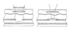
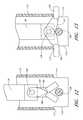
- FIG. 1Aillustrates one embodiment of the present invention in an exemplary use environment.
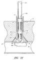
- FIG. 1Billustrates a cross-sectional view of the device in FIG. 1A in an exemplary use environment, such as a patient's thigh.
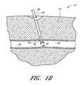
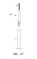
- FIG. 1Cillustrates another embodiment of the present invention in the exemplary use environment of FIG. 1A .
- FIG. 1Dillustrates a cross-sectional view of the device in FIG. 1C in an exemplary use environment, such as a human thigh.
- FIG. 2is a partial cross-sectional view of the suturing device depicted in FIG. 1A having a suture catch assembly and a suture introducer housing.
- FIG. 3is a bifurcated perspective view of the suture introducer housing of FIG. 2 .
- FIG. 4Ais a partially schematic perspective view of the suture clasp arms of FIG. 2 .
- FIG. 4Bis a partial cross-sectional view of one configuration of suture clasp arms.
- FIG. 4Cis a partial cross-sectional view of another configuration of suture clasp arms.
- FIG. 4Dis a partial cross-sectional view of yet another configuration of suture clasp arms.
- FIG. 4Eis a partial cross-sectional view of yet another configuration of suture clasp arms.
- FIG. 5is an elevational view of one configuration of a suture clasp arm.
- FIG. 6is an elevational view of another configuration of a suture clasp arm.
- FIG. 7is an enlarged elevational view of one configuration of a suture clasp.
- FIG. 8is an enlarged elevational view of a suture having bands crimped thereon.
- FIG. 9is an enlarged elevational view of another configuration of a suture clasp.
- FIG. 10is an elevational view of the suture clasp of FIG. 9 illustrating the action of a suture and the suture clasp as the suture is being removed from the suture clasp.
- FIG. 11Ais a cross-sectional top view of one configuration of a suture introducer housing, suture clasp arms, a suture, and a triangular spreader.
- FIG. 11Bis a cross-sectional side view of the suture introducer housing and triangular spreader of FIG. 11A .
- FIGS. 12 and 13are partial cross-sectional views of another configuration of a spreader for deploying the suture clasp arms.
- FIG. 14is a partial cross-sectional view of an alternate configuration of the device for deploying the suture clasp arms.
- FIG. 15is a partial cross-sectional view of an alternate configuration of suture clasp arms.
- FIG. 16is a partial cross-sectional view of the device of FIG. 15 illustrating the suture clasp arms in a deployed position.
- FIG. 17is a bifurcated perspective view of the suture catch assembly of FIG. 2 .
- FIG. 18is a partial cross-sectional view of an alternate configuration of the suture catches and the suture clasp arms.
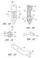
- FIG. 19is a schematic perspective view of a needle tip and one configuration of a suture catch.
- FIG. 20is a cross-sectional view of the suture catch of FIG. 19 taken along line 19 - 19 illustrating the position of a suture fitting captured by the suture catch.
- FIG. 21is a cross-sectional top view of the suture catch of FIG. 19 taken along line 20 - 20 .
- FIG. 22is a schematic illustration of another configuration of a suture fitting.
- FIG. 23is a side view of a suture clasp arm used to hold the suture fittings of FIGS. 20 and 22 .
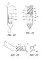
- FIG. 24is a rear elevational view of a needle tip with an alternate configuration of the suture catch.
- FIG. 25is a cross-sectional view of the needle tip of FIG. 24 taken along line 24 - 24 of FIG. 24 .
- FIG. 26is a partial cross-sectional side view of an alternate configuration of a suture clasp arm to hold a suture fitting.
- FIG. 27is an end view of the suture clasp arm of FIG. 26 .
- FIG. 28is a perspective view of a three-sector arm actuator assembly with a catch in a distal position.
- FIG. 29is a perspective view of a button of the assembly of FIG. 28 .
- FIG. 30is a perspective view of a guide of the assembly of FIG. 28 .
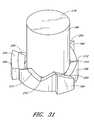
- FIG. 31is a perspective view of the catch of the assembly of FIG. 28 .
- FIG. 32is a perspective view of the assembly of FIG. 28 with the catch in a proximal position.
- FIG. 33is a schematic partial cross-sectional view of the assembly of FIG. 28 with the catch in a distal position.
- FIG. 34is a partial cross-sectional view of the suture introducer housing of FIG. 2 with the introducer over the housing.
- FIG. 35is a partial cross-sectional view of the suture introducer housing of FIG. 2 with the suture clasp arms deployed.
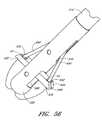
- FIG. 36is a partial cross-sectional view of the suture introducer housing and suture catch assembly of FIG. 2 illustrating the operation of the suture catch assembly.
- FIG. 37is a partial cross-sectional view of the suture introducer housing and the suture catch assembly of FIG. 2 .
- FIG. 38is a schematic view of a vessel illustrating the location of the suture.
- FIG. 39is a schematic cross-sectional view of the vessel of FIG. 38 taken along line 40 - 40 .
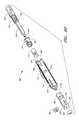
- FIG. 40is a partial schematic cross-sectional view of one configuration of the suturing device having a detachable arm deployment handle.
- FIG. 41is a cross-sectional view of the embodiment depicted in FIG. 1C with the distal end inserted through an arterial wall.
- FIG. 42is a cross-sectional view of the device of FIG. 41 with the suture clasp member partially deployed.
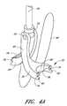
- FIG. 43Ais a perspective view of a suture clasp member, an actuator and a hollow elongated body of FIG. 41 .
- FIG. 43Bis an exploded view of the suture clasp member, pivot pin and actuator of FIG. 42 .
- FIG. 43Cis a perspective view of a two-piece suture clasp member.
- FIG. 43Dis a cross-sectional view of the two-piece suture clasp member of FIG. 43C and a spreader within the suture introducer head of FIG. 41 .
- FIG. 44is a perspective view of the suture introducer head and suture clasp member of FIG. 41 .
- FIG. 45is perspective view of the device of FIG. 44 with the suture clasp member partially deployed.
- FIG. 46is a rear perspective view of the device of FIG. 44 .
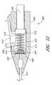
- FIG. 47is cross-sectional view of the device of FIG. 41 with the suture clasp member fully deployed.
- FIG. 48is a cross-sectional view of another embodiment of the present invention.
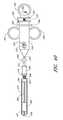
- FIG. 49is a cross-sectional view of one embodiment of a handle capable of being attached to the proximal end of the device of FIG. 41 , the device of FIG. 48 or the device of FIG. 52A .
- FIG. 50is a perspective view of the handle of FIG. 49 .
- FIG. 51is a cross-sectional view of another embodiment of a handle capable of being attached to the proximal end of the device of FIG. 41 , the device of FIG. 48 or the device of FIG. 52A .
- FIG. 52Ais a perspective view of the suture introducer head and the hollow elongated body of FIG. 41 with another embodiment of the suture clasp arms.
- FIG. 52Bis a cross-sectional view of the device of FIG. 52A .
- FIG. 53A-53Bare perspective views of one configuration of the suture clasp member of FIG. 52A .
- FIG. 54is a perspective view of the device of FIG. 52A with the suture clasp member partially deployed.
- FIG. 55is a perspective view of the device of FIG. 52A with the suture clasp member fully deployed.
- FIG. 56is a perspective view of the device of FIG. 52A with the suture clasp member fully deployed and needles engaging the suture clasp member.
- FIG. 57is a perspective view of the handle of FIG. 49 .
- FIGS. 58-59are perspective views of a four-arm suture clasp member used with the device of FIG. 1C-1D .
- FIG. 60is an exploded view of another embodiment of a handle capable of being attached to the proximal end of the device of FIG. 41 , the device of FIG. 48 or the device of FIG. 52A .
- FIG. 61is a perspective view of the handle of FIG. 60 .
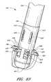
- FIG. 62is a perspective view of another configuration of the suture introducer head and the hollow elongated body of FIG. 52A with six suture clasp arms.
- FIG. 63is a perspective view of the device of FIG. 62 with the suture clasp arms fully deployed.
- FIG. 64is a perspective view from the distal end of the device of the six suture clasp arms of FIG. 62 .
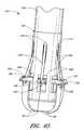
- FIG. 65is a perspective view of the device of FIG. 62 with the suture clasp arms fully deployed and a set of needles engaging the suture clasp arms.
- FIG. 66is a perspective view from the distal end of another suture device configuration of the present invention with four suture clasp arms.
- FIG. 67is a perspective view of the suture device of FIG. 66 with the suture clasp arms fully retracted.
- FIG. 68is a perspective view of the suture device of FIG. 66 with the suture clasp arms partially deployed.
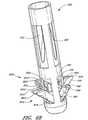
- FIG. 69is a perspective view of the suture device of FIG. 66 with the suture clasp arms fully deployed and a set of needles.
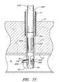
- FIGS. 70-71illustrate a removable sheath that may be used with the suture devices shown in FIGS. 1A-69 .
- FIGS. 72-73illustrate occlusion devices that may be used with the suture devices shown in FIGS. 1A-69 .
- FIG. 74Ais an exploded cross-sectional view of another embodiment of a handle capable of being attached to the proximal end of the device of FIG. 41 , the device of FIG. 48 or the device of FIG. 52A .
- FIG. 74Bis an exploded cross-sectional view of another embodiment of a handle adapted to separately actuate the first and second needles.
- FIGS. 75A and 75Bare exploded, cross-sectional, perspective views of the handle of FIG. 74A .
- FIG. 76Ais an exploded, cross-sectional, perspective view of the handle of FIG. 74B .
- FIGS. 76B-Dschematically illustrate various embodiments of the needle drivers adapted to separately actuate the first and second needles.
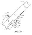
- FIG. 77illustrates the suture device of FIG. 56 adapted to move a first needle distally to engage a first suture clasp arm before moving a second needle distally to engage a second arm.
- FIG. 78illustrates the suture device of FIG. 77 with the second needle moving distally.
- FIG. 79illustrates the suture device of FIG. 77 with the first needle piercing a first biological tissue portion and engaging the first suture clasp arm.
- FIG. 80illustrates the suture device of FIG. 77 with the second needle piercing a second biological tissue portion and engaging the second suture clasp arm.
- FIG. 81illustrates the first and second biological tissue portions being drawn together by a suture inserted by the suture device of FIG. 77 .
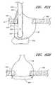
- FIG. 82Aillustrates the suture device of FIG. 77 with a patch deployed from the elongated body.
- FIG. 82Billustrates the patch of FIG. 82A occluding the suture site.
- FIG. 83Aillustrates a patch connected to the ends of the suture before distally sliding the patch toward the suture site.
- FIG. 83Billustrates the patch of 83 A occluding the suture site with a knot securely holding the patch in place.
- FIG. 84illustrates a patch with two pairs of sutures through the patch.
- FIG. 85illustrates a suture device with a steerable portion and a first needle piercing a first biological tissue portion.
- FIG. 86illustrates the suture device of FIG. 85 with a second needle piercing a second biological tissue portion.
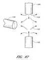
- FIGS. 87-102illustrate methods of forming suture ends of a suture which may be used with the suture devices described herein, in which:
- FIG. 87shows a strand of material being brought into a stream of hot gas
- FIG. 88shows a distal end of the strand being thermally deformed to form a deformed region such as a globule
- FIGS. 89 and 90show a die for flattening the deformed region
- FIG. 91shows the strand after the deformed region has been flattened
- FIG. 92shows the strand after excess material has been cut away from the deformed region
- FIG. 93shows the strand after an eyelet has been formed in the flattened, deformed region
- FIG. 94shows a suture in which eyelet portions have been formed at both ends of the suture
- FIG. 95shows the deformed region placed between two blocks having recessed portions therein
- FIG. 96shows the deformed region after it has been squeezed between the blocks to form a cylindrically shaped member
- FIG. 97shows a hole being formed in the deformed region with a hypotube
- FIG. 98shows the formed hole in the deformed region, resulting in a cup-like member at the end of the strand
- FIGS. 99 and 100show views of a one embodiment of a surgical needle to be used with the cup-like member of FIG. 98 ;
- FIG. 101shows the surgical needle having entered the cup-like member and secured to it.
- FIG. 102shows an embodiment having cup-like members at both ends of the suture.
- FIG. 103Ashows a side view of the distal portion of the device with one end portion of the suture captured by a needle extended through the tissue structure and a second end portion of the suture looped around a second tissue structure.
- FIG. 103Bshows a side view corresponding to FIG. 103A once the end portions of the suture have been tied together and tightened.
- FIGS. 1A-1Billustrate one embodiment of the present invention in an exemplary use environment.
- the physicianmakes an initial incision 20 in the upper thigh 12 of a patient 2 .
- the physicianthen inserts a needle (not shown) into the incision 20 .
- the physicianknows the needle has pierced the femoral artery 16 .
- the physicianthen inserts a guidewire (not shown) through the needle and into the artery.
- the physicianmay take the needle out and insert a plastic needle (not shown) over the guidewire once the guidewire is in place.
- the guidewiremay then be taken out.
- CSIcatheter sheath introducer
- This introducer sheath 6is typically a single lumen catheter with a valve on its proximal end. The valve is used to prevent extraneous bleed back or to introduce medication into the patient's body.
- the vessel incision 26provides access for medical instruments and probes inside the arterial vessel 16 . Instruments may be inserted into artery 16 via the introducer sheath 6 to perform various procedures in the body.
- the suture assembly 4consists of the suture catch assembly 36 (described below), the suture introducer housing 24 , and the introducer sheath 6 .
- FIG. 1Billustrates a cross-sectional view of the device depicted in FIG. 1A in an exemplary use environment, such as a patient's thigh.
- the physicianwithdraws the CSI 6 and inserts the suture catch assembly 36 and the suture introducer housing 24 through the first incision 20 .
- the suture catch assembly 36 and suture introducer housing 24pass through the flesh 14 of the patient's thigh 12 and through the second incision 26 into the femoral artery 16 .
- the physicianmay first insert the suture introducer housing 24 , remove the CSI 6 , and then insert the suture catch assembly 36 .
- FIGS. 1C and 1Dillustrate another embodiment of the present invention in the exemplary use environment of FIG. 1A .
- the device illustrated in FIGS. 1C-1Ddoes not require the removal of the CSI 6 in order for the device to deploy a suture.
- FIGS. 1A and 1Bwill now be described with reference to FIGS. 2-40 .
- the device depicted in FIGS. 1C-1Dwill thereafter be described in further detail below with reference to FIGS. 41-50 .
- FIGS. 1A-1B and 2 - 40Embodiments of FIGS. 1A-1B and 2 - 40
- FIG. 2shows one embodiment of the suturing device for suturing vessel walls and other biological tissue.
- the deviceis for use in suturing arterial vessel walls 22 .
- the devicecould be used to suture other tissue such as a patent ductus arteriosus, a patent foramen ovale, a heart defect, a puncture wound, and the like.
- the suturing devicecomprises a suture introducer housing 24 for insertion into an opening 26 in the arterial wall 22 .
- Suture clasp arms 28 , 30are deployably housed in the housing 24 during insertion. After insertion into the vessel 16 , the arms 28 , 30 are deployed to the position shown in FIG. 2 . When deployed, the suture clasp arms 28 , 30 extend outside the circumference of the suture introducer housing 24 . In certain embodiments, the arms 28 , 30 extend from the housing in a symmetric configuration, in which each arm 28 , 30 has the same angle with respect to the axis of the housing 24 . Alternatively, in other embodiments, each arm 28 , 30 can extend from the housing in an asymmetric configuration, in which each arm 28 , has a different angle with respect to the axis of the housing 24 .
- the arms 28 , 30are spaced equidistantly around the circumference of the housing 24 .
- Equidistant spacingas used herein means that the azimuthal angle between the two arms 28 , 30 is 180 degrees, where the azimuthal angle between the two arms 28 , is the angle between the plane defined by the axis of the housing 24 and the first arm 28 and the plane defined by the axis of the housing 24 and the second arm 30 .
- the arms 28 , 30are spaced non-equidistantly around the circumference of the housing 24 (e.g., the azimuthal angle between the two arms 28 , 30 is 90 degrees).
- Each armhas at least one suture clasp 32 , schematically illustrated, for clasping a suture 40 .
- a penetrating mechanism, generally designated 34is provided for penetrating the vessel wall 22 .
- the penetrating mechanism 34is provided on either the suture introducer housing 24 or on a suture catch assembly, generally designated 36 .
- the penetrating mechanism 34also comprises suture catches 38 for catching the suture 40 and dislodging it from the suture clasps 32 .
- the suture catch assembly 36operates to pull the suture 40 held by the suture catches 38 through the vessel wall 22 . After the ends of the suture 40 are pulled outside the vessel wall 22 , the introducer housing 24 can be removed and the suture 40 tied to close the vessel opening 26 .
- FIG. 3shows one configuration where the suture introducer housing 24 is a generally cylindrical and thin walled hypo tube.
- the term “hypo tube”is used to describe a hollow elongated cylindrical member with a thin wall such that the inner diameter and outer diameter vary by a relatively small amount in the range of few thousandths of an inch to tens of thousandths of an inch.
- the outer surface 42 of the housing 24comprises a key way groove 44 (exaggerated for clarity) to align the housing 24 with a key 46 ( FIG. 17 ) on the inner surface 48 of the suture catch assembly 36 .
- An arm actuation assembly 170for deploying the suture clasp arms 28 , 30 protrudes from the proximal end of the housing 24 , and an actuating wire or rod 50 extends from the actuation assembly 170 through the housing 24 to the suture clasp arms 28 , 30 .
- FIG. 2shows one configuration where the suture clasp arms 28 , 30 are attached to the distal end 54 of the actuating rod 50 .
- the arms 28 , 30are pivotally attached to the actuating rod 50 and pivot around pivot shaft 56 .
- the suture 40is held inside the housing 24 and is positioned underneath the spreader 102 , so that it can be removed from the entire housing 24 .
- the arms 28 , 30which are shown in more detail in FIGS. 4A and 4B , terminate with the suture clasps 32 (schematically illustrated).
- Each arm 28 , 30has an elongated body 58 which attaches to the pivot shaft 56 at one end and to the suture clasp 32 at the other. The length of the body 58 controls how far beyond the circumference of the suture introducer housing 24 the arms 28 , 30 extend when they are deployed by the actuating rod 50 .
- the proximal sides of the suture clasp arms 28 , 30 near the slots 76 which receives the suture 40are substantially parallel to the vessel wall 22 when the arms 28 , 30 are deployed within the vessel 16 .
- the proximal sides of the suture clasp arms 28 , 30can then provide mechanical support for the vessel wall 22 in the region of the opening 26 .
- the proximal sides of the suture clasp arms 28 , 30have an upward curvature near the slots 76 , thereby defining a proximally projecting portion on the proximal side of each of the arms 28 , 30 .
- proximal side of the arms 28 , 30provide mechanical support for the vessel wall 22 while the proximally projecting portions provide an improved purchase on the vessel wall 22 .
- This configurationthen reduces the probability of slippage of the arms 28 , 30 relative to the vessel wall 22 when the arms 28 , 30 are deployed within the vessel 16 .
- Other configurationscan have multiple proximally projecting portions on each arm 28 , 30 , or can have proximally projecting portions which are protuberances on the proximal sides of arms 28 , 30 without upward curvature. These proximally projecting portions can have various cross-sectional shapes, such as triangular or trapezoidal.
- Still other embodimentscan have relatively small proximally projecting portions which have areas smaller than the area of the proximal side of the arms 28 , 30 .
- other embodimentshave proximally projecting portions which are in proximity to the portion of the arms 28 , 30 which mount the end portions of the suture, such as the slots 76 illustrated in FIG. 4C .
- the proximally projecting portionscan also be located in proximity to the ends of the arms 28 , 30 away from the pivot shaft 56 .
- FIG. 4Dillustrates such proximally projecting portions on arms 28 , 30 such as those described below in conjunction with FIGS. 43-47
- FIG. 4Eillustrates such proximally projecting portions on arms 28 , such as those described below in conjunction with FIGS. 52-56 .
- FIG. 5shows an alternate configuration of the arms 28 , 30 .
- the arms 28 , 30are Y-shaped with an offset body 64 , and there is a suture clasp at each tip 60 , 62 of the Y-shaped arm.
- the body 64is off center from the tips 66 , 68 , so that a complimentary arm can pivot on the same pivot shaft 56 without interference.
- the Y-shape of the armsallows them to pivot beside each other outwardly from and inwardly to their undeployed position without interference from the other arm.
- the Y-shape of the armalso provides an open area or suture catch receiving area 80 into which the suture catch 30 fits to catch the suture 40 .
- Other arm shapessuch as the h-shaped arm shown in FIG.
- the h-shaped armhas a body 70 with an aperture 71 for attachment to a pivot shaft 56 and each tip 72 , 74 of the arm is provided with a suture clasp.
- the body of the h-shaped armis positioned all the way to the side of the arm and functions similarly to the Y-shaped arm.
- the configuration of the suture clasp arm shown in FIG. 6also has a suture catch receiving area 80 A.
- FIGS. 7 and 8illustrate one configuration of the suture clasp 32 , which comprises a key hole shaped slot 76 which widens toward the end of the tip to receive the suture 40 .
- a loop 78is tied in each end of the suture 40 .
- the loop 78is sized to fit tightly between the suture clasps 32 on each arm 28 , 30 .
- the key hole shaped slot 76is elongated and narrows away from the end of the tip 60 to a neck 82 having a width W.
- the end 84 of the slot 76is circular with a diameter greater than the neck width W.
- the diameter of the circular end 84 of the slot 76is sized to receive either the outer diameter of a suture 40 , shown in FIG.
- the suture 40 or the bands 86have an outer diameter approximately the same size as the diameter of the end of the slot 76 but smaller than the neck width W. Because the diameter of the bands 86 (or suture 40 ) is smaller than the width of the neck 83 , the bands 86 snap into the end of the slot 76 and are securely held therein until removed by the suture catch 38 . In an alternate configuration ( FIG. 14 ), it is desirable for the slots 76 to open upwardly when they are in the deployed position, so that the suture 40 is pulled straight up out of the slots 76 .
- FIG. 9shows another configuration of the suture clasps 32 .
- the arm 28 , 30comprises a shaft 88 extending to a plate or bar 90 .
- a resilient element 92such as a spring, is attached at each end of the bar 90 , and tips 94 are attached to the end of each resilient member 92 .
- the tips 94have slots as previously described and shown by FIG. 7 .
- the suture 40has beads 96 fixed thereto or knots tied therein. The beads are spaced apart by a distance just less than the distance between the outer edges 98 of the tips 94 . With this distance between the beads 96 , the tips 94 must be slightly bent toward each other thereby loading the resilient members 92 to receive the suture 40 .
- the tips 94are pulled inwardly and the resilient members 92 loaded, the suture 40 is held in place by the force from the resilient members 92 . Therefore, the suture 40 is held in tension between the tips 94 .
- the resilient members 92When the suture catch 38 is guided through the suture catch receiving area 100 , the resilient members 92 are further deformed as the suture 40 is forced to make an arc to receive the suture catch 38 as illustrated in FIG. 10 . The resilient members 92 then bend in the direction that the suture catch 38 is retracted, so that the suture 40 slides smoothly out of the clasp 32 . If desired, the outer edges 98 of the tips may be indented 99 to receive and more securely hold the beads 96 or knots on the suture 40 .
- FIG. 14illustrates an alternate configuration of the suture clasp slot.
- the slot 127opens upwardly toward the penetrating mechanism instead of transverse to the penetrating mechanism as in the previous configuration.
- FIG. 11Ais a cross-sectional top view of one configuration of the suture introducer housing 24 , the clasp arms 28 , 30 , the suture 40 , and a triangular spreader 102 .
- FIG. 11Ashows the triangular spreader 102 extending across a diameter line of the suture introducer housing 24 .
- the spreader 102may be shaped in alternative forms other than a triangle.
- FIG. 11Bis a side view of one configuration of the suture introducer housing 24 , the triangular spreader 102 and the direction of the clasp arms 28 , 30 as they extend downward into the blood vessel 16 .
- One vertex 104 of the triangular spreader 102is positioned centrally in the housing 24 and extends upwardly.
- the triangleis preferably isosceles with respect to the upward extending vertex 104 , so that the arms 28 , 30 spread uniformly when they engage the spreader 102 and pivot about the pivot shaft 56 .
- Each arm 28 , 30ultimately extends the same distance beyond the circumference of the housing 24 .
- the surfaces of the spreader 102 and arms 28 , 30 which engage to deploy the armsare preferably smooth, so that the deployment of the arms 28 , 30 is smooth.
- FIGS. 12 and 13Another configuration for deploying the suture clasp arms is shown in FIGS. 12 and 13 .
- the arms 106are pivotally attached to the actuating rod 50 with a pivot shaft 109 , and a circular spreader bar 108 or cam pin extending across a diameter line of the housing 110 .
- the actuating rod 50forces the suture clasp arms 106 to engage the circular spreader 108 , they are forced into the deployed position of FIG. 13 .
- the bottom surface 107 of the arms 106forms a curved camming surface for engaging the circular spreader 108 .
- the housing 110has two slit shaped openings 112 evenly spaced around the circumference of the housing 110 through which the arms 106 extend into the deployed position.
- the end of the openings 112also forms a stop 113 to prevent the arms 106 from moving past the deployed position.
- the shape of the arms 106is simplified. Because the arms 106 do not have to curve down out of the housing 110 , the arms 106 are straighter than in the previous configurations.
- Each clasp armcomprises an upper lever arm 114 pivotally attached at one end to the actuating rod 50 with a pivot shaft 116 and a lower pivot arm 118 pivotally attached to the other end of the upper lever arm 114 .
- the lower pivot arm 118rotates around a pivot shaft spreader 120 which is attached to the housing 122 and extends across a diameter line of the housing 122 .
- the upper lever arm 114rotates relative to the pivot shaft 116 , and the junction 124 between the upper and lower arms is translated downward (distally) and outwardly toward the circumference of the housing.
- the actuating rod 50is retracted from the housing, the junction is moved upward and centrally in the housing 122 , and the lower pivot arm 118 is rotated to the retracted position shown in partial dashed lines.
- the housing 122similar to the configuration of FIG. 13 , has slit openings 126 .
- the openings 126extend a greater distance along the length of the housing 122 than in FIG. 13 to allow room for the lower pivot arm 118 to exit the housing 122 and provide sufficient room for the junction 124 to move outwardly.
- a stop 129 attached to the upper lever arm 114is placed between the upper lever arm 114 and the lower pivot arm 118 to prevent the arms from moving past the deployed position.
- the stop 129can be inherent in the lower pivot arm 118 and upper lever arm 114 . This would include a notch on the side of one of the arms which the other arm would contact to limit the movement of the arms.
- FIG. 14illustrates the use of a sealing member 52 inside the suture introducer housing 24 .
- the sealing member 52prevents blood flow back through the housing 122 .
- FIGS. 15 and 16Still another configuration of the clasp arm deployment mechanism is illustrated in FIGS. 15 and 16 .
- a single resilient arm 128is attached to the actuating rod 50 .
- the resilient arm 128is predisposed in a deployed configuration shown in FIG. 16 .
- the prongs 130 of the arm 128are elastically deformed inwardly.
- the prongs 130expand to the predisposed deployed position.
- This configurationis easily adaptable to having four prongs 130 spaced at ninety degrees.
- any configuration and number of prongscan be incorporated into the device depending on the specific needs of the application.
- FIGS. 2 and 17illustrate a preferred configuration of the suture catch assembly 36 with a generally cylindrical outer tube 132 , which, as described above, includes a key 46 to mate with the key way groove 44 of the suture introducer housing 24 .
- the inner diameter of the tube 132is sized to fit over the outer diameter of the suture introducer housing 24 without any interference. This fit does not need to be tight because the suture catch assembly 36 is not inserted into the opening 26 of the vessel 16 . Therefore, there is no need to prevent the flow of blood between the suture housing 24 and the suture catch assembly 36 .
- the fit between the suture catch assembly 36 and the suture introducer housing 24does need to be close enough to assure that the suture catch 38 is properly aligned with respect to the suture clasps 32 . Proper alignment is accomplished by a close fit between the key 46 and the key way groove 44 .
- the catch assembly 36comprises a plurality of, preferably two, apertures 134 for slidably receiving respective needles 136 or other penetration members.
- the apertures 134extend through the length of the tube 132 and may be equally spaced around the circumference of the tube 132 in one configuration of the device.
- the blunt ends 138 of the needles 136are connected to an activation ring 140 , and springs 142 are interposed between the activation ring and the tube 132 .
- the springs 142hold the needles in a retracted position so that the needle points are within the tube 132 . With the needles 136 biased in a retracted position by the springs, the suture catch assembly 36 can be handled without the chance of inflicting an unintentional puncture wound.
- At least one stop 144is fixed on the inner surface 48 of the tube 132 and engages the top 146 of the suture housing 24 to fix the relative position between the suture housing 24 and the catch assembly 36 . Because the spring 142 can only be compressed a certain distance, the depth of entry of the needles 136 into the vessel 16 is controlled to prevent puncturing the opposite side of the vessel 16 . Furthermore, the fixed relative position between the suture housing 24 and catch assembly 36 assures that the needles 136 pass far enough into the suture catch receiving area 80 to catch the suture 40 .
- each needle 136Near the end of each needle 136 is the suture catch 38 .
- the suture catch 38is an aperture extending to the outer edge on one side of the needle 136 .
- the apertureis slot shaped and angled upwardly toward the proximal end of the device. While the needles are being pulled from the vessel 16 , the suture 40 is pulled to the bottom of the suture catch 38 where it cannot come loose.
- FIG. 18shows an alternate configuration of a penetrating mechanism, generally designated 150 , with the suture introducer housing 152 .
- the penetrating mechanismcomprises needle points 154 press fit onto arms 156 .
- the end of the arms 156 opposite the needle points 154are fixed to the actuating rod 50 .
- the arms 156are made of a resilient material exhibiting shape memory such as NITENOL, and the arms 156 are at rest in a deployed position shown in dashed lines. When the arms 156 are within the suture housing 152 , they are deformed to fit within the housing 152 .
- the arms 156return to their at-rest position with the needle points 154 beyond the circumference of the housing 152 .
- the suture 40is attached to the needle points 154 .
- the needle points 154are then pulled upward by the actuating rod 50 toward the vessel wall 22 , thereby penetrating the vessel wall 22 from within the vessel 16 .
- the suture catch 158has a V-shaped notch 160 with rounded tips 162 . There is a slit 164 extending up from the vertex of the notch 160 . The rounded tips 162 prevent the suture catch 158 from inadvertently puncturing the vessel wall 22 .
- the needle points 154fit into the notches 160 and cause the notches 160 to open farther along the slits 164 .
- the notch 160collapses to its original shape and traps the needle points 154 inside.
- the suture catch 158is then pulled proximally until the press fit between the needle points 154 and the arms 156 is overcome, and the needle points 154 are separated from the arms 156 .
- the actuation rod 50is then moved proximally to pull the arms 156 both into the housing 152 .
- an alignment mechanismcan be provided such as the key way described above. But in the configuration shown, the notch is circumferential. Thus, no alignment mechanism is needed, and any number of arms 156 extending from the actuating rod can be provided.
- the suture catch 158can be positioned over an introducer 168 if desired. If the proximal end of the introducer 168 is too large for the suture catch 158 to fit over, the suture catch 158 could be made of a flexible material with a longitudinal slit over its entire length allowing it to be expanded to fit around the diameter of the introducer 168 . The arms 156 would be modified so that the needle points 154 extend beyond the circumference of the introducer 168 .
- FIGS. 19 through 23illustrate an alternate configuration of the suture catch and suture clasp.
- a needle 400is provided with a slotted opening 402 having a peg 404 extending from the top of the opening 402 through a portion thereof.
- the peg 404has a narrow and rounded front peg surface 406 with an identical radial location on the needle 400 as the outer surface of the needle 400 .
- the back peg surface 408 of the needle 400is relatively wide, rounded, and located toward the radial center of the needle 400 .
- the peg sides 410are flat and angled relative to the walls 412 of the slotted opening 402 .
- the slotted opening 402receives suture fitting 414 having a shaft 416 connected, preferably by crimping, to the suture 40 and an enlarged termination 418 which is preferably spherical.
- the alternate suture fitting 420 of FIG. 22has a half spherical termination 422 with rounded edges.
- the half spherical termination 422does not protrude beyond the diameter of the needle 400 .
- This half spherical termination 422reduces the trauma to the vessel wall 22 when the needle 400 is retracted.
- the shaft in either configurationhas a length short enough not to protrude from the diameter of the needle 400 when the suture fitting is held by the needle 400 . This also reduces trauma to the vessel wall 22 during retraction.
- the suture fitting 414is held by a modified suture clasp arm 424 having an aperture 426 to receive the shaft 416 of the suture fitting 414 .
- the wall 428 of the apertureis slowly tapered so that the diameter decreases as the aperture 426 moves inwardly in the arm 424 .
- This frustoconical shapeprovides a secure press fit with the suture fitting shaft 416 .
- Other aperture shapesare possible so long as the press fit is secure and is of a force which can be overcome by the retraction of the arm 424 .
- the shaft 416 of the suture fittingscan also be tapered to better mate with the aperture 426 .
- the termination 418 , 422engages the peg 404 forcing it to one side allowing the termination 418 , 422 to slide against the peg 404 until the termination 418 , 422 is past the peg 404 .
- the peg 404snaps toward its at rest central position thereby capturing the termination 418 , 422 and hence the suture 40 .
- the suture clasp arm 424is retracted, the press fit is overcome and the suture fitting 414 is pulled from the arm 424 .
- the peg 404snaps back into its central position, it tends to pull the suture fitting 414 away from the suture clasp arm 424 . This can be utilized to help overcome the press fit. With the suture filling securely held, the needles are retracted, the suture fittings 414 cut from the suture 40 , and the suture 40 tied.
- FIGS. 24 and 25illustrate another configuration of the suture catch.
- a needle 450is provided with a slot shaped opening 451 with a U-shaped raised portion 452 in the lower front of the slot 451 .
- the opening 451also defines a suture fitting receiving area 454 at the top of the opening 451 for receiving a suture fitting 456 and a suture fitting catch area 458 in the lower back of the slot adjoining the raised portion 452 .
- the suture fitting 456has a spherical tip 459 , and an arcuate neck 460 which tapers down to a cylindrical shaft 462 .
- the spherical tip 459is sized to fit through the suture fitting receiving area 454 but not through the U-shaped raised potion 452 .
- the raised portion 452holds the suture fitting 456 in the suture fitting catch area 458 .
- the raised portion 452angles toward the back of the needle 450 , so that it becomes larger as it extends farther down the needle 450 .
- FIGS. 26 and 27show another configuration of the suture clasp arms 464 , which comprises an upwardly facing key hole shaped opening 466 for holding the suture fitting 456 .
- the opening 466faces upwardly, that is in the direction of needle retraction, to aid in the removal of the suture fitting 456 from the suture clasp arm 464 .
- the suture catchis activated to penetrate the tissue to be sutured.
- the suture clasp arms 464are deployed directing the suture fitting 456 into the suture fitting receiving area 454 .
- the neck 460 of the suture fitting 456is engaged by the raised portion 452 , and the angled surface of the raised portion 452 pulls the suture fitting 456 farther and farther toward the back of the needle.
- the suture fitting 456is being pulled out of the suture clasp arm 464 as the needle 450 is retracted. If the suture fitting 456 is not completely removed from the suture clasp arm 464 when it contacts the bottom of the opening 451 , it is snapped upwardly pass a neck 468 of the key hole opening 466 and out of the suture clasp arm 464 .
- the control of the distal and proximal translation of the actuating rod 50is preferably performed by the three sector, arm actuator assembly, generally designated 170 , which is attached to the suture introducer housing 24 (see FIG. 3 ).
- Each sector of the arm actuator assembly 170is substantially identical.
- FIGS. 28-31show that the arm actuator handle is comprised of three pieces: a button 172 , a cylindrical guide 174 , and a catch 176 .
- the button 172comprises an actuation post 178 extending centrally from a closed end of a cylindrical body 180 .
- the cylindrical body 180is sized to longitudinally slide in the guide 174 .
- Three button tabs 182are spaced equally around the outer surface of the cylindrical body at the end opposite the actuation post 178 . Thus, there is one button tab 182 in each sector.
- the catch 176comprises three catch tabs 184 corresponding to the three button tabs 182 , a cylindrical body 186 which is sized to fit rotatably inside the cylindrical body 180 of the button 172 , and a control ring 188 at an end of the cylindrical body 186 for engaging the three button tabs 182 .
- the control ring 188is at the end of the catch 176 corresponding to the end of the button 172 having the button tabs 182 , and the catch tabs 184 which rotate from sector to sector extend radially from the central ring 188 .
- the guide 174which is attached at its proximal end to the housing, has three channels 190 and three notches 192 , and the guide 174 is open at both ends; so that the button 172 protrudes from the proximal end, and the catch 176 can extend from the opposite (distal) end.
- the button tabs 182 and the catch tabs 184are slidable within the channels 190 , each button tab 182 stays in the same channel 190 while each catch tabs 184 is rotated from a channel 190 to a notch 192 and to another channel 190 during operation.
- the outer diameter of the button 172is sized to slide inside the guide 174 .
- the diameter of the control ring 188is sized to rotate freely within the guide 174 with minimum clearance, and the catch cylindrical body 186 is sized to rotate and slide longitudinally inside the button cylindrical body 180 with minimum clearance. This leaves a relatively large catch gap 196 between the catch cylindrical body 186 and the guide 174 . Therefore, the length of the catch cylindrical body 186 is preferably long enough so that it is never withdrawn from the button cylindrical body 180 during operation.
- the button tabs 182have a thickness sufficient to extend across the gap 194 and into the channels 190 .
- the button tabs 182also overlap the diameter of the control ring 188 , so that the button tabs 182 can engage the control ring 188 .
- the bottom surface 195 of the button 172is contoured to mate with the control ring 188 .
- the catch tabs 184have a diameter and thickness so that they slide in the channels 190 and fit into the notches 192 .
- the outer diameter of the guide 174is the largest diameter thereby assuring adequate clearance for translation of the button 172 and catch tabs 184 .
- the catch 176starts out in a proximal position with the catch tabs 184 in the channels 190 as shown in FIG. 32 .
- a rotation spring 198is held in compression between fixed plate 200 , which is attached to the housing 24 , and the catch 176 .
- the rotation spring 198biases the catch 176 in the proximal direction, which corresponds to a retracted suture clasp arm position.
- the catch 176rotates in the direction of arrow 202 in FIG. 32 .
- the rotationis created by the rotation spring 198 pushing a top angled surface 204 of the catch tab 184 against the bottom angled surface 206 of the button tabs 182 .
- the physicianagain depresses the actuating post 178 , so that the button tabs 182 engage the V-shaped depressions 212 in the control ring 188 located between the catch tabs 184 .
- Thispushes the catch tabs 184 below the bottom of the guide 174 .
- the rotation spring 198 pushing upward on the guide 174causes the slide surface 214 of the V-shaped depression 212 to slide across the bottom surface of the button tab 182 causing the catch tabs 184 to rotate and move upwardly until they engage the angled bottom return surfaces 216 of the guide 174 .
- a button spring 218can be provided between the catch 176 and the button 172 to return the button 172 to an upward position after it is released. If the button spring 218 is used, the button tabs 182 contact the tops of the channels 190 preventing the button 172 from coming off the assembly.
- the suture clasp arms 28 , 30are completely deployed when the catch tab 184 is in the notch 192 against the notch stop 210 .
- the catch tab 184is pushed below this level several times.
- a resilient member 220is placed in the actuating rod 50 .
- the resilient member 220is compressed allowing the catch tab 184 to be moved the rest of the way below the bottom surface of the guide so that it can rotate to the next position. This prevents damage to the spreader 102 , bending the actuating rod 50 , and risk of injury to the vessel 16 .
- the vertex 222 of the button tab 182is not aligned with the bottom of the V-shaped depression 212 when the V-shaped depression 212 is aligned with the channel 190 .
- the vertex of the depressions 212is positioned to a side of the vertex of the button tab 182 in the rotational direction, so that the catch 176 is allowed to rotate until it is underneath the shallow end of the return surface 216 of the guide 174 .
- the catch tab 184when the catch tab 184 is inside the channel 190 , the angled surfaces 224 of the control ring 188 corresponding to the catch tab 184 continue past the catch tabs 184 to again allow initial rotation of the catch 176 until the catch tab 184 is beneath the shallow end of the notch surface.
- the catch tab 184can rotate underneath the shallow end of the notch 192 before the button tabs 182 contact the lowest point of the control ring surfaces 224 and rotation is restricted.
- the actuation post 178is released raising the button tab 182 out of the way, and the catch 176 can complete its rotation.
- FIGS. 1 , 2 and 34 through 36The operation of the device is illustrated in sequence by FIGS. 1 , 2 and 34 through 36 .
- the introducer sheath 6is left in place, and the suture introducer housing 24 is inserted into the introducer 6 and introduced into the artery 16 as shown in FIGS. 1A and 1B .
- the actuation post 178is then depressed, as illustrated by arrow 240 in FIG. 35 to deploy the suture clasp arms 28 , 30 outwardly as illustrated by arrows 242 so that portions, preferably the ends, are positioned on opposite sides of the opening 26 with the suture 40 extending transverse to the flow of blood.
- the introducer 6is then removed, leaving the suture introducer housing 24 with the suture clasp arms 28 , 30 deployed inside the artery 16 .
- the opening 26 in the vessel 16closes around the housing 24 after the introducer 6 is removed.
- the suture introducer housing 24is then oriented so that the arms 28 , 30 extend transversely to the flow of blood through the vessel 16 which is illustrated by arrow 244 .
- the suture catch assembly 36is then inserted over the housing 24 and the stop 144 is brought into contact with the top 146 of the housing 24 as shown in FIG. 2 .
- a physiciandepresses the activation ring 140 as illustrated by arrows 246 ( FIG.
- the suture catch 38catches the suture 40 , and the suture catch assembly 36 is pulled proximally as illustrated by arrows 250 ( FIG. 37 ).
- the needles 136can be retracted inside the suture catch assembly 36 or left deployed.
- the suture 40is cut from the suture catch 38 and pulled tight to remove it from the housing 24 .
- the suture clasp arms 28 , 30are retracted by depressing the actuation post 178 again, and the suture 40 is pulled tight simultaneously with the housing 24 being pulled out of the artery 16 .
- the length of the actuation post 178is set to correspond with the height of the depressed activation ring 140 .
- the actuation post 178is simultaneously depressed for the second time thereby retracting the arms 28 , 30 simultaneously with pulling the suture catch assembly 36 proximally.
- the pattern of holes shown in FIGS. 38 and 39is left.
- the suture 40closes the artery vessel opening 26 transverse to the flow of blood. This is the most efficient direction to close the opening 26 .
- additional suture clasp armsit is preferred that they make additional holes around the circumference of the opening as shown in dashed lines in FIG. 38 , so that sutures again pull the opening 26 closed in a direction transverse to the flow of blood.
- the present inventioncould be similarly used to close a patent ductus arteriosus, a patent foramen ovale, a heart defect, a puncture wound in the skin, and other tissues requiring suturing.
- a heart septal defectsuch as an atrial septal defect (ASD)
- the suturing devicemay be used to close the defect opening by approximating the tissue surrounding the defect opening.
- Access to such heart septal defectscan be provided by inserting a catheter including the suturing device into the right atrium via the inferior vena cava and the femoral artery.
- access to such heart septal defectscan be provided by inserting the catheter including the suturing device into the right atrium via the superior vena cava and the subclavian vein or internal jugular vein.
- the needles 136can be extended to puncture through the tissue of the septal wall surrounding the ASD to engage the suture 40 with the suture catches 38 . Retracting the needles 136 then pulls the suture 40 through the septal wall, and further tension applied to the suture 40 closes the ASD by approximating the surrounding tissue of the septal wall.
- Similar procedurescan be used to repair other septal defects such as patent foramen ovales, ventricle septal defects (VSD), endocardial cushion defects, or septal defects existing in conjunction with Tetralogy of Fallot.
- VSDventricle septal defects
- endocardial cushion defectsor septal defects existing in conjunction with Tetralogy of Fallot.
- the suturing devicemay be used in conjunction with a patch.
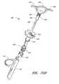
- FIG. 40An alternate configuration of the suturing device is shown in FIG. 40 .
- the devicecomprises a pair of suture clasp arms 270 attached to the end of an actuating rod 272 in accordance with one of the above described configurations.
- the actuating rodextends through a needle cover 274 and slidably through a needle actuator 276 to a suture arm deployment handle 278 .
- the actuating rod 272Near the deployment handle 278 the actuating rod 272 has, a severable junction 279 .
- the junction 279is threaded or snap fit allowing the actuating rod 272 to be quickly separated and joined thereby quickly removing or attaching the handle 278 from the remainder of the device.
- the actuating rod 272can, in the alternative, have a junction where it enters the needle cover 274 .
- Needles 280are held near their distal ends by a needle guide 282 and pass through a stop 284 that limits the deployment distance of the needles 280 .
- the needles 280fixably attaching to the needle actuator 276 .
- a spring 286is interposed between the stop 284 and the needle actuator 276 to bias the needles 280 in a retracted position.
- a second stop 288is fixed to the actuating rod 272 on the opposite side of the needle actuator 276 to prevent the needles 280 from being pulled out of the needle guide 282 .
- the actuating rod 272terminates at a thumb ring 290 separated from the distal end of the suture arm deployment handle 278 by a thumb ring spring 292 which biases the thumb ring 290 in a proximal position which corresponds to a retracted position of the suture clasp 270 .
- the handle 278also comprises two finger rings 294 , 296 on opposite sides of the handle allowing a physician to smoothly overcome the force of the thumb ring spring 292 .
- the distal portion of the deviceis inserted into the introducer 6 with the handle 278 detached.
- the introducer 6is removed and the handle 278 is attached to the device by connecting the actuating rod 272 .
- the thumb ring 290is pushed distally to deploy the suture clasp arms 270 .
- a clip 298hooks onto a clip ring 300 to lock the suture clasp arms 270 in the deployed position.
- the actuating rod 272includes a resilient member 302 (shown schematically), which functions, as described in the previous configurations, to prevent the suture clasp arms 270 from moving past their deployed position.
- the resilient member 302can simply comprise a spring, or a spring housing can be provided on one part of the actuation rod 272 to receive a spring and a slidable plunger therein.
- the plungerwhich is provided on the opposite part, slides to a maximum distal position defined by the spring housing and is biased in that position by the spring.
- the plungerWhen the suture clasp arms 270 reach a deployed position, the plunger is then forced into the spring housing, compressing the spring and allowing the upper portion of the actuation rod 272 to travel distally without forcing the suture clasp arms 270 past a deployed position or bending the actuation rod 272 .
- a thumb ring stop 304prevents the thumb ring 290 from being pushed beyond a point for which the resilient member 302 could compensate.
- the physiciangrasps the needle actuator 276 , which has a central curved indented surface 306 to make it easy to grasp, and pushes the needle actuator 276 distally.
- the needles 280are pushed into the vessel 16 and catch the suture 40 as described in one of the above configurations.
- the stop 284prevents the needles 280 from penetrating too far and damaging the vessel 16 .
- the spring 286pushes the needles 280 back to a retracted position when the needle actuator 276 is released.
- the thumb ring 290is pushed in a direction transverse to the length of the actuating rod and away from the clip 298 as illustrated by arrow 308 to release the clip 298 and retract the suture clasp arms 270 .
- the entire deviceis retracted, the suture 40 cut from the needles 280 , and the suture 40 tied to close the opening 26 .
- the handle 278is detachable, the handle 278 could be used in conjunction with the above described configurations. In such a case, the arm actuator assembly would be removed, and the actuating rod 50 would extend through the top of the housing 24 . The end of the actuating rod 50 would be modified to connect to the handle 278 .
- FIGS. 1C-1D and 41 - 50Embodiments of FIGS. 1C-1D and 41 - 50
- the suture introducer housing 24 and the suture catch assembly 36consist of two separate pieces, wherein the suture catch assembly 36 operatively fits around the suture introducer housing 24 .
- the physicianfully removes the original CSI 6 before inserting the suture catch assembly 36 to penetrate the blood vessel wall and catch the ends of a suture.
- the removal of the CSI 6 and the introduction of the suture catch assembly 36may disturb the flesh 14 or enlarge the incision 20 and add to the complexity of the procedure.
- FIGS. 1C-1D and 41 - 50do not require the full removal of the original CSI 6 (used for the original percutaneous approach procedure, such as an angioplasty/angiography procedure) in order for the device to catch the ends of a suture. Rather, as depicted in FIG. 41 , the distal portion of the device 520 passes through the CSI 6 and the flesh 14 of the patient's thigh 12 with minimal disturbance to the flesh 14 , and through the second incision 26 into the femoral artery 16 .
- FIGS. 41-48illustrate the device 520 depicted in FIG. 1C-1D where the suture introducer housing and the suture catch assembly are integrated into a single suture insertion and retraction device 520 .
- This suturing device 520may comprise a one-piece suture insertion and retraction housing 515 as shown in FIG. 48 , or may comprise a suture introducer head 522 attached to the distal end of a hollow elongated body 514 as shown in FIG. 41 .
- the suture introducer head 522 and the hollow body 514are narrower in diameter than the configurations illustrated in FIGS. 1A-1B and 2 - 40 because the suture clasp member 500 and the needles 546 reside in the same longitudinal space.
- the needles 546share the same housing as the suture clasp member 500 (while they are all in their retracted state), but are higher up (proximally) in the suturing device 520 than the suture clasp member 500 .
- An important feature of this embodimentis that it uses flexible needles 546 which bend outward, away from the axis of the device 520 , when in the extended position (as shown in FIG. 47 ).
- the dimensions of the suturing device 520may vary according to the suture site and the biological tissue intended to be sutured.
- the diameter of the suture introducer head 522is about 0.105 inches
- the diameter of the hollow elongated body 514is about 0.098 inches.
- the suture introducer head 522has two needle ports or apertures 510 formed therein (one per needle 546 ) proximal to the suture clasp arms 524 .
- Each needle portincludes a needle guiding portion 512 (“needle guide”), in the form of an outwardly curved groove or channel, which guides the corresponding needle 546 along a particular path.
- the needle guides 512may be formed within the suture introducer head 522 (as shown in FIG. 41 ) as part of a mold, or may be separate pieces (not shown) that are inserted into the suture introducer head 522 during manufacture.
- FIGS. 41-48Another advantage of the embodiments illustrated in FIGS. 41-48 is the required size of the initial incision 20 into the patient's body and the diameter of the introducer sheath 6 used to insert the device 520 may be reduced.
- the size of the suture device 520may vary depending on the application and the size of the vessel incision 26 .
- FIG. 46shows a preferred configuration of the hollow elongated body 514 with five lumens.
- Two of the lumens 516are used to house the needles 546 ( FIG. 41 ).
- Another lumen 530is used to house the actuating rod 50 .
- Another lumen 532is used to hold the length of the suture 40 to prevent the suture 40 from becoming tangled.
- the suture 40may be stored in the actuating rod lumen or in a hole drilled into the suture clasp arm 500 .
- the fifth lumen 534is preferably used for ‘bleed back,’ which lets the physician determine whether the distal end 504 of the suture introducer head 522 is still positioned in the artery 16 after the physician removes the catheter sheath introducer (CSI) 6 .
- Bleed backis accomplished by the hole 540 ( FIG. 45 ) at the distal end 504 of the suture introducer head 522 , the suture clasp arm apertures 508 and any other openings in the suture introducer head 522 .
- the direction of blood flow for bleed backis shown by the dashed arrows in FIGS. 41 and 48 .
- the bleed back lumen 534extends to a port (not shown) at a proximal portion of the device, and the physician can observe the blood pressure through bleed back lumen 534 by monitoring blood flow from the port.
- the bleed back lumenmay be attached to a balloon which inflates when the distal portion 504 of the suture introducer head 522 is within the blood vessel 16 .
- a pressure sensoris associated with the blood flow lumen 534 to provide the physician with a numeric reading.
- the fifth lumen 534may be used to inject medication or for diagnostic purposes.
- two thin stripes 538are marked on the exterior of the elongated body 514 which denote the circumferential location of the two needles 546 . These stripes extend along a portion of the elongated body 514 which is outside the patient's body. These stripes help the physician to align the needles 546 with the axis of the blood vessel 16 , so that the needle incisions 248 ( FIG. 47 ) will be longitudinally aligned. As described above for FIG. 38 , the suture 40 closes the artery vessel opening 26 transverse to the flow of blood. This is the most efficient direction to close the opening 26 .
- the needles 546Proper insertion of the needles 546 reduces the risk of damage to the vessel walls 22 , 506 .
- the physicianwill know the circumferential location of the other needle 546 because the needles 546 are 180 degrees apart.
- the exterior surface of the elongated body 514includes a marker 539 which denotes the proximal position to which the CSI 6 should be partially withdrawn (after the distal portion of the suturing device 520 has been inserted into the blood vessel 16 ) to expose the needle apertures 510 .
- the partial withdrawal of the CSI 6is described below.
- the marker 539is shown as a visual marker, but may additionally or alternatively be in the form of a ridge, groove, or other physical structure which interacts with a corresponding structure of the CSI to allow the physician to position the CSI using the sense of feel.
- the CSI 6 and elongated body 514could be configured to releasably engage or interlock with one another when the CSI reaches the proper position along the body 514 .
- a specially formed CSIwhich includes such an interlocking structure is included within the scope of the invention.
- One or more additional longitudinal markerscould be provided along the body 514 , distal to marker 539 , to indicate other relative positions of the CSI and the body 514 , such as the position at which the retractable arms 524 are exposed outside the CSI.
- the device 520includes a single, resilient suture clasp member 500 attached to the actuating rod 50 .
- This resilient suture clasp member 500is preferably of a unitary construction as shown.
- the suture clasp member 500comprises a center or hinge portion 542 and two suture clasp arms 524 (one for each needle 546 ).
- Each suture clasp arm 524has a suture clasp 544 at the end thereof.
- the hinge portion 542 of the suture clasp member 500acts as a “living hinge” because it has a memory which causes the member 500 to return to a partially open, unretracted position ( FIG. 42 ) when a force (applied via rod 50 ) is released.
- FIGS. 41 and 42This can be seen in FIGS. 41 and 42 .
- the suture clasp member 500is deployed in the artery 16 in its predisposed (relaxed or natural) position.
- the suture clasp member 500is retracted into the suture introducer head 522 in its compressed (stressed or tensed) position.
- the arms 524are moved to the retracted position by applying a distal force to the actuator rod 50 , which causes the arms to contact deflection surfaces 518 ( FIG. 42 ).
- This suture clasp member 500is preferably composed of a resilient shape memory material such as NITENOL.
- the suture clasp member 500may alternatively be composed of another material with spring-like characteristics, such as plastic, spring steel, stainless steel or any variations thereof. Further, the suture clasp member 500 could be composed of two arms that are hingedly connected to the actuating rod 50 without the use of a resilient hinge, as shown in FIGS. 43C and 43D and described below.
- the living hinge configurationis easily adaptable to having three arms spaced at 120 degrees or four arms (as in FIGS. 58 and 59 ) spaced at ninety degrees. If there are three arms, then there are preferably 3 needles 546 and six lumens in the elongated body 514 . Thus, other configurations and numbers of arms can be incorporated into the device to accomplish the specific needs of the application.
- the needles 546are flexible and preferably made from a material with shape memory, such as SUPERFLEX NITENOL. Alternatively, the needles 546 may be composed of spring steel, surgical stainless steel or any variation thereof. The diameter of the needles 546 is preferably about 0.019 inches, but needles with other diameters may be used in accordance with the present invention.
- the needle insertion guidescause the needles 546 to bend radially outward.
- the needles 546also preferably further bend slightly (radially outward) when they come in contact with the angled surfaces 545 of the suture clasp arms 524 , as shown in FIG. 47 .
- the needles 546are retracted into the needle lumens 516 , they resume a straight configuration as a result of their resiliency.
- FIGS. 41-48preferably uses flexible needles which bend during deployment, it is contemplated that non-bending needled, which may be either straight or curved, could alternatively be used.
- the actuating rod 50attaches to the resilient suture clasp member 500 by a pivot pin 502 .
- the actuating rod 50 in this configurationpreferably comprises a single shaft (as shown), but may comprise a plurality of shafts in other configurations.
- FIG. 43Cis a perspective view of a non-living hinge embodiment or a two-piece suture clasp member 501 .
- FIG. 43Dis a cross-sectional view of the two-piece suture clasp member 501 and a ramp or spreader 523 within the suture introducer head 522 .
- the hinge portion of the suture clasp arms 525 , 525 ′ with suture clasps 544may be similar to a hinge portion shown in FIG. 53 , which is described below.
- the spreader 523may be a separate piece attached within the suture introducer head 522 .
- the spreader and suture introducer head 522may comprise a single molded piece.
- the length of the suture clasp arm 525is preferably about 0.174 inches.
- the length of both of the suture clasp arms 525 , 525 ′ together in their fully extended position (deployed with both arms parallel to each other)is preferably about 0.288 inches. In other configurations of the suture clasp arms 525 , 525 ′, the dimensions may vary.
- the actuating rod 50is advanced distally, and the interior edges 518 of introducer head 522 come in contact with the suture clasp arms 525 , 525 ′ The interior edges 518 of introducer head 522 cause the two suture clasp arms 525 , 525 ′ to retract radially inward relative to the actuating rod 50 .
- the general use and operation of the two-piece suture clasp member 501is similar to the use and operation of the suture clasp member 500 shown in FIG. 43A , as described below.
- the proximal portion of the suturing device 520preferably includes a handle which allows the physician to externally operate the suture clasp arms 524 and the needles 546 inside the blood vessel 16 .
- This handlepreferably has three actions: a first action in which the actuating rod 50 applies a proximal force to the hinge portion 542 to deploy and maintain the arms 524 in a fully outward position ( FIG. 47 ); a second action to advance the needles 546 distally ( FIG. 47 ) and pull the needles 546 back proximally using one or more springs; and a third action in which the actuating rod 50 applies a distal force to the hinge portion 542 to retract the arms 524 ( FIG. 41 or 48 ).
- the handlemay be a 2-action handle in which one of the two actions is a combination of two of the three actions described above for the 3-action handle.
- the actuating rod 50applies a proximal force to the hinge portion 542 to deploy and maintain the suture clasp arms 524 in a fully extended state of FIG. 47 .
- the needles 546automatically advance distally ( FIG. 47 ) and retract proximally to capture the looped ends of the suture 40 .
- the actuating rod 50applies a distal force to the hinge portion 542 to retract the arms 524 ( FIG. 41 or 48 ).
- This 2-action handleis suited for physicians with more experience in operating this suture device 520 . It will be apparent to one of ordinary skill in the art that a 1-action handle or a 4-action handle (inserting and withdrawing the needles 546 as two separate actions) could be used, or that separate handles or triggers could be provided for different actions.
- FIG. 49is a cross-sectional view of one embodiment of a handle 550 operatively attached to the proximal end of the hollow elongated body 514 of FIG. 41 or the single suture insertion and retraction housing 515 of FIG. 48 or the device of FIG. 52A .
- FIG. 50is a perspective view of the handle 550 .
- FIG. 57is a perspective view of the handle 550 of FIG. 49 .
- the handle 550comprises an actuating rod aperture 551 , a main housing 552 , a pair of finger grips 554 , a suture clasp arm piston 556 with a locking groove 576 , a needle piston 560 with at least one raised key portion 562 , a releasor 568 with a locking stopper 572 , a pivot pin 570 , a releasor support 574 , a compression spring (not shown) operatively positioned in a spring recess 578 between the suture clasp arm piston 556 and the needle piston 560 , a needle piston support cylinder 580 with at least one grooved recess 564 and needle clamps 584 .
- the housing 552is attached to or is a continuation of the hollow elongated body 514 of FIG. 41 or the single suture insertion and retraction housing 515 of FIG. 48 .
- the housing 552is separate from the hollow elongated body 514 or single suture insertion and retraction housing 515 .
- the actuating rod 50connects the housing 552 with the hollow elongated body 514 or single suture insertion and retraction housing 515 .
- a proximal portion of the actuating rod 50slides through the actuating rod aperture 551 at the distal end of the housing 552 .
- the proximal end of the actuating rod 50is attached to the distal end 558 of the suture clasp arm piston 556 , which is slidably received within the main housing 552 .
- a compression spring(not shown) resides in the spring recess 578 of the housing 552 between the suture clasp arm piston 556 and the needle piston 560 and simultaneously exerts two forces: a distal force on the suture clasp arm piston 556 ; and a proximal force on the needle piston 560 .
- the needle clamps 584 of the needle piston 560hold the proximal ends of the needles 546 .
- the needle piston 560is slidably received within a distal portion of the housing 552 .
- the needle piston support cylinder 580is attached to the housing 552 and preferably does not move relative to the housing 552 .
- the releasor 568pivots radially inward and outward on the pivot pin 570 .
- the releasor support 574exerts a radially outward force on the releasor 568 . This force causes the releasor 568 to pivot and the locking stopper 572 to fall into the locking groove 576 of the suture clasp arm piston 556 when the locking groove 576 is aligned to receive the locking stopper 572 .
- the releasor support 574is preferably made of a resilient shape memory material such as NITENOL.
- the releasor support 574may alternatively be composed of another material with spring-like characteristics, such as plastic, spring steel, stainless steel or variations thereof. Other embodiments of the handle are described below with reference to FIGS. 57 , 60 and 61 .
- the physicianinserts the suture introducer head 522 through a catheter sheath introducer (CSI) 6 and into the artery 16 ( FIGS. 1C-1D ).
- the CSI 6is then partially withdrawn along the body 514 of the suturing device 520 to remove the CSI 6 from the artery 16 and expose the needle apertures 510 , as shown in FIG. 41 .
- the distal end 504 of the introducer head 522has a smooth, rounded surface to prevent injury to the opposite vessel wall 506 when inserting the introducer head 522 .
- the blood flow in the artery 16is uninterrupted because the introducer head 522 does not occlude the artery 16 .
- the physicianmay use the aperture 540 at the distal end of the suture introducer head 522 and the bleed back lumen 534 to determine when the distal end 504 of the suture introducer head 522 is in the artery 16 .
- the actuating rod 50holds the resilient suture clasp member 500 in its compressed position within the introducer head 522 .
- the actuating rod 50applies a downward force while the interior edges 518 of the introducer head 522 apply an inward force on the two suture clasp arms 524 .
- the combination of these two forcescause the hinge portion 542 of suture clasp member 500 between the two arms 524 to elastically deform or compress.
- the suture clasps 544hold the looped ends of a suture 40 in the angled slot of the suture clasps 544 as shown in FIGS. 41-43A .
- the looped ends of the suture 40are held securely by the suture clasps but are positioned for easy removal by the suture catches 38 of the needles 546 .
- the physicianmay deploy the suture clasp arms 524 ( FIG. 42 ) by pulling the finger grips 554 in a proximal direction relative to the housing 552 ( FIG. 50 ).
- a physicianmay pull the suture clasp arm piston 556 proximally by placing the physician's index and middle finger around the finger grips 554 and pushing on the proximal end 582 of the housing 552 . This action is similar to operating a standard syringe. This motion compresses the spring (not shown) in the spring recess 578 of the handle 550 in a proximal direction.
- the actuating rod 50moves in a proximal direction relative to the elongated body 514 or housing 515 . This is shown by the arrows in FIG. 42 .
- This motioncauses the suture clasp member 500 to deploy or open to its predisposed or natural position as shown in FIG. 42 .
- the suture clasp arms 524deploy out of the introducer head 522 into the blood vessel 16 through two suture clasp arm apertures 508 ( FIG. 42 ), one on either side of the introducer head 522 .
- the locking stopper 572 at the distal end of the releasor 568moves radially inward and falls into the locking groove 576 of the piston 556 .
- the locking stopper 572in combination with the locking groove 576 , prevents the suture clasp arm piston 556 from advancing distally.
- the force of the spring in recess 578prevents the suture clasp arm piston 556 from moving proximally.
- the locking of the suture clasp arm piston 556stabilizes the suture clasp arms 524 in a locked position before the needles 546 are advanced distally.
- the suture clasp arms 524preferably have reached their fully extended position, as shown in FIG. 47 .
- the actuating rod 50(attached to the suture clasp arm piston 556 ) has pulled the resilient suture clasp member 500 up, and the proximal inside edges 536 of the aperture 508 have come in contact with the arms 524 of the suture clasp member 500 .
- FIG. 47The pulling of the actuating rod 50 and the stationary inside edges 536 of the apertures 508 cause the arms 524 to bend backward until the arms 524 are longitudinally aligned with each other, as shown in FIG. 47 .
- the resilient suture clasp member 500is deformed from its natural configuration again, but this time in an extended position instead of a compressed position.
- the physicianmay move the suturing device 520 proximally so that the arms 524 touch the interior of the vessel wall 22 while the needles 546 advance distally and capture the ends of the suture 40 from the suture clasps 544 .
- the physiciantwists the needle piston 560 clockwise or counter-clockwise until the raised key portion 562 of the needle piston 560 matches the grooved recess 564 of the needle piston support cylinder 580 .
- the grooved recess 564 of the needle piston support cylinder 580allows the raised key portion 562 of the needle piston 560 to advance distally. Otherwise, the needle piston 560 may not be advanced distally if the raised key portion 562 does not match the grooved access 564 .
- the needle piston support cylinder 580 and the raised key portion 562 of the needle piston 560prevent the needles 546 from advancing distally prematurely or improperly. Premature or improper insertion of the needles may cause damage to the patient's surrounding tissue 14 ( FIGS. 1B and 1D ) or the blood vessel 16 .
- the physicianmay advance the proximal end of the needle piston 560 (with the physician's thumb or palm) in a distal direction relative to the proximal end 582 of the housing 552 . This motion compresses the spring in the spring recess 578 in a distal direction.
- the needle piston 560advances distally, the needles 546 and the suture catches 38 on the needles ( FIG. 47 ) also advance distally.
- the paths taken by the needles 546are illustrated in FIG. 47 .
- the needles 546slide along the needle housings 516 (or needle lumens) and out of the suture device 520 through needle apertures 510 .
- the needles 546come in contact with the needle insertion guides 512 , the needles 546 begin to bend radially outward.
- the needles 546 exitthey are guided at a radially outward, acute angle away from the actuating rod 50 by the needle insertion guides 512 .
- the angle of the needle deflectionis preferably 13.2 degrees. Deflection angles in the ranges of 10 to 15 degrees and 5 to 20 degrees are also contemplated.
- the needles 546then penetrate the vessel wall 22 at an angle by creating incisions 248 on either side of the main vessel incision 26 .
- the needles 546also preferably bend slightly (radially outward) when they come in contact with the suture clasp arms 524 .
- the combination of the suture clasps 544 and the suture catches 38 on the needles 546creates a lock on the looped ends of the suture 40 , such that the suture ends will not fall off while the needle 546 engages the suture clasp member 500 .
- the physicianadvances the needle piston 560 distally until the resistance of the compression spring prevents the needle piston 560 from advancing any further distally.
- the needles 546are sufficiently advanced in the blood vessel 16 such that when the needles 546 are pulled back proximally, the suture catches 38 on the needles 546 will catch the looped ends of the suture 40 from the suture clasps 544 .
- the clasp arms 524hold the suture loops away from the suture introducer head 522 , so that the needles 546 pierce the vessel 22 and catch the suture loops outside the perimeter of the suture introducer head 522 .
- the physicianadvances the needle piston 560 to its farthest distal position, the physician releases the needle piston 560 .
- the compressed springcauses the needle piston 560 to immediately spring back proximally. This motion causes the distal portion of the needles 546 to immediately spring back proximally into the needle housing 516 with the looped ends of the suture 40 attached to the suture catches 38 .
- the suture catches 38 on the needles 546catch the suture loops held by the suture clasps 544 and pull the ends of the suture 40 up through the punctured holes 248 when the needles 546 are retracted proximally.
- the needles 546are retracted into the needle lumens 516 , they resume a straight configuration.
- a segment of the suture 40is released (as a result of the tension caused by the retracting needles 546 ) through an aperture 540 at the distal end 504 of the suture introducer head 522 and into the artery 16 .
- the physicianpresses the proximal portion of the releasor 568 in a radially inward direction. This motion causes the releasor 568 to pivot.
- the locking stopper 572moves radially outward and releases the locking groove 576 .
- the force of the compressed springcauses the suture clasp arm piston 556 and the actuating rod 50 to advance distally. Together with the proximal interior edges 518 of the introducer head 522 , the downward force of the actuating rod 50 causes the resilient suture clasp member 500 to retract into its compressed position. As shown in FIGS.
- the suture clasp arms 524retract into respective apertures or grooves 508 on the exterior surface of the introducer head 522 .
- the arms 524are substantially parallel with the elongated body 514 .
- the exterior surfaces of the arms 524are flush with the exterior surface of the introducer head 522 . This reduces the likelihood that the arms 524 will catch on the vessel wall 22 or flesh 14 during withdrawal.
- the device 520is now ready for removal from the blood vessel 16 .
- the physicianwithdraws the device 520 out of the blood vessel 16 and out of the flesh 14 of the patient's thigh 12 .
- the physicianpulls the ends of the suture 40 and closes the main vessel incision 26 .
- the physicianthen ties at least one knot with the ends of the suture 40 and slides or pushes the knot(s) down through the CSI 6 to the vessel incision 26 .
- the physicianmay fasten a small, circular or flat stainless steel clip (not shown) to the ends of the suture 40 and slide the clip down through the CSI 6 to the vessel opening 26 to close the opening 26 .
- the physicianthen cuts the unused ends (extra length) of the suture 40 and removes the cut portions.
- the physicianremoves the CSI 6 from the patient's thigh 12 .
- FIGS. 41-48Some of the advantages of the suturing device 520 shown in FIGS. 41-48 will now be described in greater detail.
- the device 520 shown in FIGS. 41-48deploys its suture clasp arms 524 in a radial direction without extending beyond the distal end 504 of the device 520 .
- this device 520reduces the likelihood that the suture clasp arms 524 will contact and damage the inner vessel wall 506 opposite the incision 26 .
- the locked position of the suture clasp arms 524provides a stable base or foundation for holding the looped ends of the suture 40 while the needles 546 come in contact with the suture clasp arms 524 and capture the suture 40 .
- the suture clasp arms 524are locked in the locked position by the proximal force of the actuating rod 50 , the stationary inside edges 536 of the apertures 508 and the protrusions 528 at the ‘elbow’ end of each arm 524 ( FIG. 47 ).
- each arm 524becomes substantially parallel with each other (i.e., each arm 524 is at an angle of approximately 90 degrees from the actuating rod 50 )
- the protrusions 528 at the ‘elbow’ end of each arm 524come into contact with each other and prevent the arms 524 from bending any further than the configuration shown in FIG. 47 .
- the suture clasp member 500cannot open any farther, even when the needles 546 are inserted distally and come in contact with the suture clasp arms 524 .
- the protrusions 528prevent the suture clasp member 500 from moving unintentionally (opening any farther) when the needles 546 come in contact with the suture clasp arms 524 .
- the shape and position of the angled slits of the suture clasps 544 in FIGS. 41-48provide another advantage.
- the slits of the suture clasps 544 in FIGS. 41-48are angled in a proximal, radially inward direction.
- the face of the looped ends of the suture 40face in a proximal, radially inward direction. In this configuration, there is less chance of the looped ends of the suture 40 falling off the suture clasps 544 improperly or prematurely.
- the only direction the looped ends may moveis in a proximal, radially inward direction, which is in the opposite direction of the inserted needles 546 .
- the needles 546retract proximally (as shown in FIG. 47 )
- the looped endsreliably fall into the suture catches 38 of the needles 546 .
- This configurationdoes not rely on a radially outward tension in the looped ends to fasten the looped ends onto the suture catches 38 when the needles 546 are inserted distally.
- retractable suture clasp armsare used to hold the suture 40 beyond the outer circumference of the tubular housing (and thus beyond the boundaries of the incision 26 ), and flexible needles 546 are used to capture the held suture 40 outside the outer circumference.
- the suture clasp assemblymay be in the form of a fixed (non-moving) member which holds the suture near or within the circumference of the housing.
- curved needlesmay be used which pierce the vessel wall outside the circumference of the housing and then “curve in” to capture the suture. The curved needles may then be withdrawn to pull the ends of the suture out of the vessel wall.
- FIG. 51is a cross-sectional view of another embodiment of a handle 600 attached to the proximal end of the hollow elongated body 514 of FIG. 41 or the single suture insertion and retraction housing 515 of FIG. 48 or the device of FIG. 52A .
- the handle 600 of FIG. 51comprises a housing 602 with a spring recess 622 , a pair of external finger grips 604 (only one shown in FIG. 51 ), a suture clasp arm piston 606 with a locking groove 608 , a releasor 612 with a locking head 610 and a needle piston stopper 618 , a pivot pin 614 , a needle piston 620 with needle clamps 616 and a spring 624 .
- the handle 600also includes a second spring (not shown) which biases the releasor 612 toward a position in which the locking head 610 is engaged with the groove 608 .
- the finger grips 604extend outside the housing 602 to allow a physician to move the piston 606 relative to the housing 602 .
- the needles 546 in FIG. 51are attached to the needle clamps 616 , which is attached to the needle piston 620 .
- the actuating rod 50( FIG. 41 ) is attached to the suture clasp arm piston 606 in FIG. 51 .
- the general operation of the handle 600 shown in FIG. 51is similar to the operation of the handle 550 shown in FIGS. 49-50 .
- the needle piston stopper 618prevents the needle piston 620 from distally advancing prematurely or improperly. This function is similar to the function of the raised key portion 562 and grooved recess 564 of the handle 550 shown in FIGS. 49-50 .
- the physicianadvances the suture clasp arm piston 606 proximally against the biasing force of the spring 614 (by pulling the finger grips 604 proximally) to deploy the suture clasp arms 524 ( FIG. 42 ) until the locking head 610 of the releasor 612 moves radially inward and falls into the locking groove 608 .
- the clasp arms 524are in the fully deployed or open position as in FIG. 47 .
- This motioncauses the proximal portion of the releasor 612 to advance radially outward until the needle piston stopper 618 is no longer blocking the needle piston 620 .
- the physicianmay advance the needle piston 620 distally into the recess 622 to cause the needles 546 to advance distally and capture the suture 40 .
- the spring 614moves the needle piston proximally to the outward position, causing the needles 546 to retract with the suture 40 .
- the physicianpresses the external lever portion of the releasor 612 to release the suture clasp arm piston 606 ; this causes the suture clasp arms 524 to return to the retracted position, so that the device can be withdrawn from the artery 16 .
- this handleattached to the proximal end of the device 520 .
- there are at least two springs or sets of springs(not shown), instead of the single compression spring as used by the handle 550 in FIGS. 49-50 and the handle 600 in FIG. 51 .
- a first springexerts a proximal force on the needles 546 while a second spring exerts a distal force on the actuating rod 50 inside the handle.
- the physicianmanually retracts the needles 546 proximally back into the needle housing 516 .
- a handle (not shown) attached to the proximal end of the device 520is similar to the handle as shown in FIG. 40 .
- FIG. 52Ais a perspective view of the suture introducer head 522 and the hollow elongated body 514 of FIG. 41 with another embodiment of the suture clasp arms 630 , 630 ′.
- the ends of the sutureare provided with special loops 41 that are configured to engage with the needles (as described below).
- FIG. 52Bis a cross-sectional view of the device of FIG. 52A .
- FIG. 53A-53Bare perspective views of one configuration of the suture clasp arms 630 , 630 ′ shown in FIG. 52A .
- FIG. 54is a perspective view of the device of FIG. 52A with the suture clasp arms 630 , 630 ′ partially deployed.
- FIGS. 55-56are perspective views of the device of FIG. 52A with the suture clasp arms 630 , 630 ′ fully deployed.
- FIG. 56further shows two flexible needles 650 engaging the suture clasp arms 630 , 630 ′.
- a first suture clasp arm 630comprises a hinge portion 636 at a distal side with an aperture 642 for a pivot pin 502 ( FIG. 43C ).
- the first suture clasp arm 630further comprises a curved portion 638 for the distal end of an actuating rod 50 (as in FIG. 43B ) and the hinge portion 636 at a distal side of the second suture clasp arm 630 ′ ( FIG. 53B ).
- the first suture clasp arm 630further comprises an annular recess 632 for holding a suture looped end 41 and for receiving the distal portion of a needle.
- the arm 630further comprises a slit 640 for the length of the suture 40 , and a sloped end 634 .
- the distal side of the arms 630 , 630 ′are connected to the actuating rod 50 via a pivot pin 502 ( FIG. 43C ) such that the proximal sides of the arms 630 , 630 ′ may move away from the suture introducer head 522 , as shown in FIG. 54 , to a position where the proximal sides are fully extended outwardly away from the distal sides of the arms 630 , 630 ′ shown in FIGS. 52A-52B .
- the extended proximal sidesmay also be retracted towards and into the suture introducer head 522 to a retreated position (similar to the position shown in FIG. 41 ).
- FIG. 53Billustrates the second suture clasp arm 630 ′, which is the other half of a two-arm suture clasp member.
- the second suture clasp arm 630 ′is similar to first suture clasp arm 630 except the second suture clasp arm 630 ′ does not have a curved portion 638 for the distal end of an actuating rod 50 (as in FIG. 43B ).
- the length of the first suture clasp arm 630is about 0.174 inches. In one embodiment, the length of both of the suture clasp arms 630 , 630 ′ together in their fully extended position (deployed with both arms parallel to each other) is preferably about 0.288 inches. In other configurations of the suture clasp arms 630 , 630 ′, the dimensions may vary.
- each of the flexible needles 650comprises an elongated shaft, a pointed, generally conical penetrating distal tip 654 , and a groove or shoulder 652 at the base of the distal tip 654 near the distal end.
- the circumference of the looped end 41is slightly smaller than that of the base of the conical tip 654 , so that the needle groove 652 acts as a detent mechanism or suture catch.
- the grooves 652extend around the complete circumference of the needles 650 .
- the grooves 652are partially circumferential along the radial edge of the needles 650 .
- the loops 41correspond generally in circumference to grooves 652 of the needles 650 , and are sufficiently resilient to expand in circumference in response to the downward force of the needles 650 , so as to slide over the conical tip 654 .
- the looped end 41comprises an eyelet that is formed as a unitary, integral part of the suture 40 .
- the suture eyeletcomprises a flat, thin portion of suture material having a central opening that is slightly smaller than the base of the tip 654 .
- the periphery of the discis contoured to match that of the recess 632 of the clasp arms.
- the discis sized to fit within the recess and to be retained therein by interference fit.
- the looped end 41 of the suture 40may be formed by heating one end of a length of suture such as by a stream of hot gas until the end becomes a ball-shape and pliable.
- the ball-shaped endis then deformed by compressing it into a disc shape while the suture material is still pliable.
- a sharpened hypotubeis then used to punch out the hole near the center of the disc-shaped end such that the disc-shaped end forms the eyelet.
- the diskmay be bent relative to the strand while the material is pliable to put a permanent set in the bent suture.
- the suturecomprises a monofilament or plastic suture material, such as prolene or declene.
- the suture endis simply compressed and a hole is formed thereafter. The end may be further cut or stamped into a circle shape.
- the actuation of the needles 650is used to form the hole and fasten the ends of the suture to the needles 650 .
- a separately-formed loopis insert-molded, glued, crimped or otherwise attached to the end of a length of suture.
- the loopmay be in the shape of a circle, oval, triangle, rectangle, hexagon, octagon, etc.
- the general use and operation of the suture clasp arms 630 , 630 ′ in FIGS. 52A-56is substantially similar to the use and operation of the suture clasp arms 524 described above with reference to FIGS. 41-48 .
- the looped ends 41 of the suture 40are placed within the annular recess 632 of the suture clasp arms 630 , 630 ′ ( FIGS. 52A and 54 ).
- the suture introducer head 522is inserted into biological tissue (similar to FIG. 47 ), and the suture clasp arms 630 , 630 ′ are deployed radially outward ( FIG. 55 ).
- the penetrating flexible needles 650pass through the biological tissue to be sutured (similar to FIG. 47 ) and engage the suture clasp arms 630 , 630 ′ ( FIG. 56 ).
- the looped ends 41elastically stretch slightly, so as to circumferentially flex momentarily.
- the looped ends 41relax, fall into the grooves 652 , and fasten around the needle grooves 652 , such that pulling the needles 650 proximally causes the suture ends 41 to follow the proximal movement of the needles 650 .
- the grooves 652provide the same general function as the suture catches 38 (FIG. 41 ) described above with reference to FIGS. 41-42 and 47 .
- the needlesare formed without a groove or shoulder, and the shaft of the needle is sized relative to the opening in the eyelet to provide an interference fit therebetween.
- FIGS. 58-59are perspective views of a suturing device 660 with a four-arm suture clasp member used with the device of FIG. 1C-1D .
- the suturing device 660 shown in FIGS. 58-59comprises four needle apertures 670 and four suture clasp arms 662 - 668 .
- Each of the four suture clasp arms 662 - 668comprises an annular recess and a slit for the length of the suture.
- two suturesare used with the device shown in FIGS. 58-69 , each of which is held by a pair of suture clasp arms.
- Each suturehas a loop at either end which is placed within one of annular recesses of a suture clasp arm.
- the arms 662 - 668may alternatively be provided with one of the other types of suture clasp structures disclosed herein.
- FIG. 60is a perspective, exploded view of another handle configuration 700 attached to the proximal end of the device of FIG. 41 , the device of FIG. 48 or the device of FIG. 52A .
- FIG. 61is a perspective view of the handle of FIG. 60 . In FIG.
- the handle 700comprises a thumb ring 702 , a plunger 704 , a plunger distal end 706 , a main housing 710 , a proximal aperture 708 , a finger ring 712 , a sloped floater peg slot 714 , a floater clamp slot 715 , a distal end aperture 716 , a floater 720 , a peg 718 , a floater clamp lock 722 , a floater clamp 724 , a drive wire (actuating rod 50 ) clamp 726 , a needle holder backer 728 , a needle holder 730 , a floater clamp peg 732 , a floater clamp aperture 734 , a spring 736 , at least one plunger peg 738 , L-shaped lock recess 740 and an extrusion (hollow elongated body 514 ) clamp 742 .
- the spring 736 , the floater 720 , the floater clamp lock 722 , the floater clamp 724 , the drive wire clamp 726 , the needle holder backer 728 , the needle holder 730 and the extrusion clamp 732are operatively received within the main housing 710 .
- the shaft of the plunger 704is slidably received through the floater 720 , the floater clamp lock 722 and the floater clamp 724 .
- the square- or rectangular-shaped shaft of the plunger 704fits within the square- or rectangular-shaped axial recess of the floater 720 , such that rotating the plunger 704 clockwise causes the floater 720 to rotate clockwise as well.
- the plunger distal end 706is adapted to snap into or otherwise attach itself into the needle holder backer 728 .
- the plunger pegs 738are slidably received along the L-shaped lock recess 740 formed on the interior of the main housing 710 .
- the L-shaped recess lock 740 , the floater peg slot 714 and the floater clamp slot 715are all molded, carved or otherwise formed on the interior of the main housing 710 .
- the spring 736provides a proximal biasing force on the plunger pegs 738 and the plunger 704 .
- the spring 736also provides a distal biasing force on the floater 720 .
- the floater peg 718is slidably received along the sloping floater peg slot 714 .
- the distal end of the floater 720snaps and locks into the proximal portion of the floater clamp lock 722 .
- the floater clamp lock 722is preferably glued, bonded or otherwise attached to the floater clamp 724 .
- the drive wire clamp 726fits within the aperture 734 of the floater clamp 724 .
- the drive wire clamp 726is glued, bonded or otherwise attached to a proximal portion of a drive wire or the actuating rod 50 of FIG. 52B .
- the extrusion (hollow elongated body 514 ) clamp 742is glued, bonded or otherwise attached to a proximal portion of the hollow elongated body 514 of FIG. 52A .
- the needle holder 730is preferably glued, bonded or otherwise attached to the needle holder backer 728 .
- the proximal portion of the needles 546 of FIG. 47 or the needles 650 of FIG. 55are preferably glued, bonded, molded into or otherwise attached to the needle holder 730 .
- the plunger pegs 738 within the L-shaped lock recess 740prevent the plunger 704 from moving distally relative to the main housing 710 .
- the plunger pegs 738move circumferentially along the L-shaped lock recess until the plunger pegs 738 are positioned to slide distally down the longitudinal part of the L-shaped lock recess 740 .
- the floater 720As the physician rotates the plunger 704 , the floater 720 also rotates clockwise. The peg 718 moving within the sloped floater peg slot 714 causes the floater 720 to move proximally. Because the drive wire clamp 726 is attached to the drive wire or actuating rod 50 ( FIG. 52A ), the proximal movement of the floater 720 causes the floater clamp lock 722 , the floater clamp 724 , the drive wire clamp 726 , and the actuating rod 50 to move proximally, such that the suture clasp arms 630 , 630 ′ deploy radially outward ( FIG. 52A-52B ).
- the physicianmay advance the plunger 704 distally.
- the distal movement of the plunger 704causes the needles 546 ( FIG. 47 ) or the needles 650 ( FIG. 55 ) to advance distally, penetrate the biological tissue, and engage the suture clasp arms 524 , 630 , 630 ′ ( FIG. 47 and FIG. 55 ).
- the L-shaped lock recess 740prevents the plunger 704 and the needles 546 ( FIG. 47 ) or the needles 650 ( FIG. 55 ) from advancing prematurely. This prevents unintentional deployment of the needles 546 , 650 which may cause damage to the patient's tissues 14 , 22 ( FIG. 1D ).
- FIGS. 62-65illustrate another suture device configuration 750 .
- FIG. 62is a perspective view of the suture device 750 with six suture clasp arms 756 - 766 (only three of which are visible in FIG. 62 ).
- FIG. 63is a perspective view of the device 750 of FIG. 62 with the suture clasp arms 756 - 766 fully deployed.
- FIG. 64is a perspective view from the distal end of the device 750 of the six suture clasp arms 756 - 766 of FIG. 62 .
- FIG. 65is a perspective view of the device of FIG. 62 with the suture clasp arms fully deployed and a set of needles engaging the suture clasp arms.
- the structure of the suture introducer head 752is substantially similar to the suture introducer head 522 of FIG. 52A , except the suture introducer head 752 in FIG. 62 comprises six suture arm apertures 508 and six needle apertures 510 .
- the structure of the hollow elongated body 754 in FIG. 62is substantially similar to the structure of the hollow elongated body 514 in FIG. 52A , except the hollow elongated body 754 in FIG. 62 comprises six needle lumens (not shown) to house the needles 650 .
- the hollow elongated body 754 and the suture introducer head 752may be one integrated piece, similar to the device 515 in FIG. 48 .
- the suture devicemay have eight suture clasp arms, eight suture clasp arm apertures, eight needles, eight needle apertures, eight needle lumens and four sutures.
- a handle(not shown) at the proximal end of the suture device 750 which allows a physician to operate the suture device 750 .
- the handlemay be similar to any one of the handle embodiments described above and below, except that the handle for suture device 750 is adapted to operate six suture clasp arms and six needles.
- each suture clasp arm 756 - 766 of FIG. 62is substantially similar to the structure of the suture clasp arm 630 ′ in FIG. 53B .
- the structure of the suture clasp arms 756 - 766is substantially similar to the suture clasp arm 630 (with a curved portion 638 ) in FIG. 53A .
- each suture clasp arm 756 - 766comprises an annular recess 632 for holding a looped end 41 of a suture 40 .
- each suture clasp arm 756 - 766comprises a hinge portion 636 , which is similar to the hinge portion 636 shown in FIG. 53B .
- the suture introducer head 752comprises a center ring 770 with six spokes 772 .
- Each hinge portion 636is operatively attached to a spoke 772 by a pivot pin (not shown), which is substantially similar in structure and function to the pivot pin 502 in FIG. 52B .
- the center ring 770is attached to an actuating rod (not shown), which is substantially similar in structure and function to the actuating rod 50 in FIG. 52B .
- the structure of the suture 40 and the needles 650 in FIG. 62is substantially similar to the structure of the suture 40 and the needles 650 in FIG. 52A .
- Each suture 40has a loop 41 at each end of the suture 40 .
- FIGS. 62-65The general use and operation of the suture device 750 in FIGS. 62-65 is substantially similar to the use and operation of the suture devices described above with reference to FIG. 41-48 and FIGS. 52A-56 .
- a first looped end 41 of a first suture 40is placed within the annular recess 632 of a first suture clasp arm 756
- the second looped end 41 of the same suture 40is placed within the annular recess 632 of a second suture clasp arm 762
- the second suture clasp arm 762is on the opposite side (180 degrees) of the suture introducer head 752 in relation to the first suture clasp arm 756 .
- a first looped end 41 of a second suture 40is placed within the annular recess 632 of a third suture clasp arm 766
- the other looped end 41 of the second suture 40is placed within the annular recess 632 of a fourth suture clasp arm 760
- the third suture clasp arm 766is on the opposite side (180 degrees) of the suture introducer head 752 in relation to the fourth suture clasp arm 760 .
- a first looped end 41 of a third suture 40is placed within the annular recess 632 of a fifth suture clasp arm 758 , and the other looped end 41 of the third suture 40 is placed within the annular recess 632 of a sixth suture clasp arm 764 ( FIG. 64 ).
- the suture clasp arms 756 - 766may be colored to distinguish each suture clasp arm pair.
- suture clasp arms 756 and 762may be colored red
- suture clasp arms 760 , 764may be colored white
- suture clasp arms 758 and 766may be colored blue.
- the suture clasp arm pairsmay have another type of indication, such as a marking.
- the suture introducer head 752 or the elongated body 754may include an indication, such as coloring or markings to indicate the suture clasp arm pairs.
- the suture introducer head 752 of FIG. 62is inserted into biological tissue 22 (similar to FIG. 47 ).
- the physicianpreferably uses a handle to deploy the six suture clasp arms 756 - 766 radially outward ( FIG. 63 ).
- the physicianuses the handle to advance the six penetrating flexible needles 650 through the biological tissue 22 to be sutured (similar to FIG. 47 ) and to engage the suture clasp arms 756 - 766 ( FIG. 56 ) simultaneously.
- the three pairs of needles 650advance distally through the tissue 22 and engage the suture clasp arms 756 - 766 at different times.
- the needles 650When the needles 650 engage the suture clasp arms 756 - 766 , the needles 650 capture the ends 41 of the sutures 40 . The needles 650 are then withdraw proximally with the ends 41 of the sutures 40 attached. Once the needles 650 are drawn into the needle apertures 510 , the combination of the circular detents or grooves of the needles 650 and the inside surface of the suture introducer head 752 securely holds the sutures 40 or creates a lock on the sutures 40 such that withdrawing the suture device 750 will not cause the suture ends 41 to slip out of the apertures 510 .
- the physicianremoves the suture device 750 from the patient's tissues 22 , 14 ( FIG. 1B ). The physician then releases the suture ends 41 from the needles 650 and ties three knots to secure the three sutures 40 at the suture site 26 ( FIG. 1B ).
- FIGS. 66-69illustrate another suture device configuration 800 of the present invention.
- FIG. 66is a perspective view from the distal end of the suture device 800 with four suture clasp arms 804 - 810 .
- FIG. 67is a perspective view of the suture device 800 of FIG. 66 with the suture clasp arms 804 - 810 fully retracted.
- FIG. 68is a perspective view of the suture device 800 of FIG. 66 with the suture clasp arms 804 - 810 partially deployed.
- FIG. 69is a perspective view of the suture device 800 of FIG. 66 with the suture clasp arms 804 - 810 fully deployed and a set of needles 650 .
- the structure of the suture introducer head 801is substantially similar to the suture introducer head 522 of FIG. 52A , except the suture introducer head 801 of FIG. 66 has four suture clasp arm apertures 508 , four needle apertures and four needle guides 802 .
- the structure of the hollow elongated body 870 attached to proximal end of the suture introducer head 801 of FIG. 66is substantially similar to the elongated body 514 of FIG. 52A , except the elongated body 870 attached to the suture introducer head 801 has four needle lumens (not shown).
- the hollow elongated body 870 and the suture introducer head 801may be one integrated piece, similar to the device 515 in FIG. 48 .
- a handle(not shown) at the proximal end of the suture device 800 which allows a physician to operate the suture device 800 .
- the handlemay be similar to any one of the handle embodiments described above and below, except that the handle for suture device 800 is adapted to operate four suture clasp arms and four needles.
- the suture clasp arms 804 - 810 of FIGS. 66-69comprise hinge portions 820 - 826 , apertures for pivot pins (e.g., an aperture 846 and a pivot pin 842 are shown in FIG. 69 ), annular recesses for holding looped ends of a suture 40 (e.g., an annular recess 844 is shown in FIG. 68 ), sloped ends 848 - 854 for facilitating deployment of the suture clasp arms 804 - 810 , and slits 856 - 862 for the lengths of sutures 40 .
- pivot pinse.g., an aperture 846 and a pivot pin 842 are shown in FIG. 69
- annular recessesfor holding looped ends of a suture 40
- sloped ends 848 - 854for facilitating deployment of the suture clasp arms 804 - 810
- slits 856 - 862for the lengths of sutures 40 .
- the suture clasp arms 804 - 810further comprise sloped side surfaces 812 - 818 and curved recesses 828 - 834 .
- the sloped side surfaces 812 - 818facilitate deployment and/or retraction of the suture clasp arms 804 - 810 when the sloped side surfaces 812 - 818 come in contact with the edges of the suture clasp arm apertures 508 .
- the curved recesses 828 - 834are configured to accommodate the hinge portions 820 - 826 of the suture clasp arms 804 - 810 .
- the curved recess 828accommodates the hinge portion 826 and provides sufficient space for both suture clasp arms 804 , 810 to deploy and retract without hindering each other.
- the suture device 800comprises a central hinge member 836 which is attached to an actuating rod (not shown, but similar to the actuating rod 50 in FIG. 52B ) via an actuating rod aperture 838 .
- the center hinge member 836comprises four pivot pins, such as the pin 848 shown in FIG. 69 .
- the hinge portions 820 - 826 of the suture clasp arms 804 - 810rotate or pivot about the pivot pins. From a perspective view, such as FIG. 66 , the suture clasp arms 804 - 810 and the central hinge member 836 resemble a pin-wheel.
- the suture device 800further comprises a spreader 840 ( FIGS. 67-69 ).
- the structure of the spreader 840is slightly different than the spreader 523 in FIGS. 43D and 52A , but the function is the same.
- the distal end of the spreader 840 in FIG. 67is configured to spread the four suture clasp arms 804 - 810 into their deployed position when the central hinge member 836 is moved proximally.
- FIGS. 66-69The general use of the suture device 800 in FIGS. 66-69 is substantially similar to the use and operation of the suture devices described above with reference to FIGS. 41-48 , 52 A- 56 and 62 - 65 .
- a first looped end 41 of a first suture 40is placed within the annular recess of a first suture clasp arm 804
- the second looped end 41 of the same suture 40is placed within the annular recess of a second suture clasp arm 808 .
- the second suture clasp arm 808is on the opposite side (180 degrees) of the suture introducer head 801 in relation to the first suture clasp arm 804 .
- a first looped end 41 of a second suture 40is placed within the annular recess of a third suture clasp arm 806
- the other looped end 41 of the second suture 40is placed within the annular recess of a fourth suture clasp arm 810 .
- the third suture clasp arm 806is on the opposite side (180 degrees) of the suture introducer head 801 in relation to the fourth suture clasp arm 810 .
- each suture clasp arm 660 - 668(and a needle associated with each suture clasp arm 660 - 668 ) deploys and retracts within a two-dimensional plane, and the central longitudinal axis of the suturing device 660 lies within each plane.
- each suture clasp arm 804 - 810deploys and retracts off-center in relation to the central longitudinal axis of the suture device 800 .
- each suture clasp arm 804 - 810(and a needle 650 ( FIG. 69 ) associated with each suture clasp arm 804 - 810 ) deploys and retracts within a two-dimensional plane, and the central longitudinal axis of the suturing device 800 is offset or displaced from each plane.
- the plane associated with a first suture clasp arm 804is preferably parallel to the plane associated with a second suture clasp arm 808 .
- the plane associated with a third suture clasp arm 806is preferably parallel to the plane associated with a fourth suture clasp arm 810 . All of these planes are preferably parallel to the longitudinal axis.
- suture device 800is sized to fit an 8 french catheter or tube.
- the suture device 800may be sized to fit a catheter or tube that is smaller than or larger than 8 french.
- the central longitudinal axisis angularly offset from at least one of the four planes such that the central longitudinal axis intersects at least one of the four planes.
- the plane associated with a first suture clasp arm 804intersects the plane associated with a second suture clasp arm 808 .
- the plane associated with a third suture clasp arm 806may intersect the plane associated with a fourth suture clasp arm 810 .
- the needle guides 802 shown in FIG. 69preferably direct the tips of the needles 650 such that they deploy distally and retract proximally along a path that is curved in three dimensional space and which is offset from the central longitudinal axis of the suture device 800 .
- the needletipsmove both sideways and outwardly relative to the central axis.
- the path of these needle tipswill diverge from the planes as the tips move from their retracted position to their extended position.
- each suture clasp arm 804 - 810( FIG. 66 ) deploys and retracts within a two-dimensional plane which is offset from the central longitudinal axis of the suture device 800 , but each needle 850 deploys distally and retracts proximally in a two dimensional plane.
- each needle 850( FIG. 69 ) deploys distally and retracts proximally within a two-dimensional plane which is offset from the central longitudinal axis of the suture device 800 , but each suture clasp arm 804 - 810 deploys distally and retracts proximally in an arc or curve.
- this pin-wheel configuration(where the central longitudinal axis of the suturing device 800 is offset from each plane associated with a suture clasp arm 804 - 810 ) and the related variations described above are embodied in suturing devices with less than or greater than four suture clasp arms, such as two, six or eight suture clasp arms.
- the suture introducer head 802 of FIG. 66is inserted into biological tissue with the suture arms 804 - 810 withdrawn, as shown in FIG. 67 (similar to FIG. 47 ).
- the physicianpreferably uses a handle to deploy the four suture clasp arms 804 - 810 radially outward, as shown in FIGS. 68 and 69 .
- the physicianuses the handle to advance the four penetrating flexible needles 650 through the biological tissue to be sutured (similar to FIG. 47 ) and to engage the suture clasp arms 804 - 810 ( FIG. 69 ) simultaneously.
- the two pairs of needles 650advance distally through the tissue and engage the suture clasp arms 804 - 810 at different times.
- the physicianties two knots to secure the two sutures 40 .
- FIGS. 70-71illustrate a movable sheath 872 that may be used with the suture devices described above.
- the sheath 872is shown in FIGS. 70-71 in use with the suture device 800 of FIG. 67 .
- the sheath 872may be adapted for use with any of the suture devices described above with reference to FIGS. 1A-69 .
- the sheath 872comprises a thin-wail catheter which covers the entire suture device 800 or at least a distal portion of the suture device 800 .
- the sheath 872includes an opening at its distal end.
- the sheath 872does not include an opening at its distal end, but may have a perforation which can be torn by downward pressure of the suture device 800 to create an opening.
- the sheath 872is preferably formed or placed on the suture device 800 during manufacturing.
- the sheath 872comprises polyimide. Alternatively, other materials may be used instead of or in addition to polyimide.
- the sheath 872protects the exposed portions of the sutures 40 from premature displacement as the suture device 800 is inserted distally through the CSI 6 , the patient's tissue 14 and the vessel 22 .
- the sheath 872may also protect other exterior parts of the suturing device 800 and/or the tissue 14 and incision 26 ( FIG. 70 ).
- the sheath 872also protects the exposed portions of the sutures 40 as the suture device 800 is withdrawn proximally through the CSI 6 , the patient's tissue 14 and the vessel 22 .
- the userremoves the sheath 872 at least partially from the suture introducer head 801 . This is shown in FIGS. 70-71 .
- the usermanually removes the sheath 872 by sliding it proximally along the suture device 800 .
- the plunger 704 of the handle 700 in FIG. 60is attached to the sheath 872 , such that rotating the plunger 704 causes the sheath 872 to slide proximally.
- the sheath 872may be advanced distally over the suture introducer head 801 after the needles 650 have captured the ends 41 of the sutures 40 and retracted into the needle lumens. In this manner, the sheath 872 protects the exposed portions of the sutures 40 as the suture device 800 is withdrawn proximally through the CSI 6 , the patient's tissue 14 and the vessel 22 .
- FIGS. 72-73illustrate occlusion devices 880 , 890 that may be used with the suture devices described above to temporarily occlude the incision 26 and minimize the amount of blood escaping from the blood vessel 16 through the incision 26 .
- the occlusion devices 880 , 890are preferably adapted to allow blood to flow through the blood vessel 16 itself uninterrupted.
- the occlusion devices 880 , 890are adapted to occlude the entire blood vessel 16 , including the incision 26 .
- the occlusion devices 880 , 890are shown in FIGS. 72-73 in use with the suture device of FIG. 52A .
- the occlusion devices 880 , 890may be adapted for use with any of the suture devices described above with reference to FIGS. 1A-69 .
- the occlusion devicecomprises a balloon 880 which is adapted to temporarily occlude the incision 26 to be sutured.
- the balloon 880may comprise polyethylene, polyurethane, other polymers or any other material with similar properties.
- the balloon 880is attached to a hollow tube 882 which is attached to a lumen (not shown) within the suture introducer head 522 and the hollow elongated body 514 .
- the hollow tube 882may extend through the lumen within the suture introducer head 522 and the hollow elongated body 514 , and may slide within such lumen.
- the hollow tube 882may be flexible or substantially rigid.
- the hollow tube 882is used to inflate the balloon 880 .
- the balloon 882may be inflated with saline solution or any fluid that is safe for internal occlusion devices.
- inflation of the balloon 880is initiated after (1) the needles capture the ends of the suture 40 from the suture clasp arms 630 , 630 ′ and (2) the suture clasp arms 630 , 630 ′ are retracted into the suture introducer head 522 .
- the balloon 880temporarily occludes the incision 26 while the suture introducer head 522 is being withdrawn proximally from the tissue 14 and the physician is tying a knot with the suture ends.
- the physicianslides the knot distally toward the incision 26 .
- the physiciandeflates the balloon 880 and withdraws the balloon 880 from the vessel 16 and the tissue 14 . Finally, the physician then tightens the knot to close the incision 26 .
- the occlusion devicecomprises an inverting member 890 , such as the inverting members shown and described in U.S. Pat. No. 5,944,730 entitled “DEVICE AND METHOD FOR ASSISTING END-TO-SIDE ANASTOMOSIS” filed on Mar. 6, 1997, the entirety of which is incorporated by reference herein.
- the inverting member 890is attached to an actuator 892 which extends through a lumen (not shown) within the suture introducer head 522 and the hollow elongated body 514 .
- the inverting member 890comprises: an elongated shaft or tube and an expandable inverting member which forms a cup or umbrella-like structure that can be used to form a sealed pocket against the inner wall 22 of the vessel 16 .
- the inverting member 890is adapted to temporarily occlude the incision 26 to be sutured.
- the inverting member 890protrudes from the distal tip of the suture introducer head 522 .
- the inverting member 890is expanded from a collapsed configuration to an expanded configuration after (1) the needles capture the ends of the suture 40 from the suture clasp arms 630 , 630 ′ and (2) the suture clasp arms 630 , 630 ′ are retracted into the suture introducer head 522 . This is shown in FIG. 73 .
- the inverting member 890temporarily occludes the incision 26 while the suture introducer head 522 is being withdrawn proximally from the tissue 14 and the physician is tying a knot with the suture ends.
- the physicianslides the knot distally toward the incision 26 .
- the physiciancollapses the inverting member 890 so that the expanded cup is contracted against the shaft, and withdraws the inverting member 890 from the vessel 16 and the tissue 14 . Finally, the physician then tightens the knot to close the incision 26 .
- FIG. 74Ais a perspective view of another embodiment of a handle 900 capable of being attached to the proximal end of the device of FIG. 41 , the device of FIG. 48 or the device of FIG. 52A .
- FIG. 74Bis a perspective view of another embodiment of a handle 900 adapted to separately actuate the first and second needles. A portion of the main housing 910 has been removed in FIGS. 74A and 74B to expose the interior.
- FIGS. 75A and 75Bare exploded, perspective views of the embodiment shown in FIG. 74A .
- FIG. 76Ais an exploded, perspective view of the embodiment shown in FIG. 74B , and FIGS.
- FIGS. 74 B and 76 A-Dschematically illustrate various embodiments of the needle drivers adapted to separately actuate the first and second needles.
- FIGS. 74 B and 76 A-Dwill be described more fully below in connection with the non-simultaneous actuation of the first and second needles.
- the handle 900comprises a thumb ring 902 , a plunger 904 , a plunger distal end 906 , a main housing 910 , a proximal aperture 908 , a finger ring 912 , a sloped floater peg slot 914 , a floater clamp slot 915 , a distal end aperture 916 , a floater 920 , a peg 918 , a floater clamp lock 922 , a pair of finger grips 924 , a pair of needle holding apertures 926 , a rotator 930 , a 928 rotator grip, a distal portion 932 of the rotator 930 , a central lumen 934 in the rotator 930 , a spring 936 , at least one plunger peg 938 , and an L-shaped lock recess 940 .
- the handle 900further comprises other members which are substantially similar to the members of the handle 700 described above with reference to FIGS. 60 and 61 .
- These membersinclude a floater clamp (not shown), a drive wire clamp for an actuating rod 50 (e.g., FIG. 52B ), a floater clamp peg, a floater clamp aperture, and an extrusion clamp for a hollow elongated body 514 (e.g., FIG. 52B ).
- the spring 936 , the plunger 904 , the rotator 930 , the floater 920 , the floater clamp lock 922 , the floater clamp (not shown), the drive wire clamp (not shown), and the extrusion clamp (not shown)are operatively received within the main housing 910 , similar to FIG. 60 .
- the distal portion 906 of the plunger 904is slidably received through the rotator 930 , the floater 920 , the floater clamp lock 922 and the floater clamp (not shown), similar to FIG. 60 .
- the square- or rectangular-shaped distal portion 932 of the rotator 930fits within the square- or rectangular-shaped axial recess of the floater 920 , such that rotating the rotator 930 clockwise causes the floater 920 to rotate clockwise as well.
- the plunger pegs 938are slidably received along the L-shaped lock recess 940 formed on the interior of the main housing 910 .
- the L-shaped recess lock 940 , the floater peg slot 914 and the floater clamp slot 915are all molded, carved or otherwise formed on the interior of the main housing 910 .
- the spring 936provides a proximal biasing force on the plunger peg 938 and the plunger 904 .
- the spring 936also provides a distal biasing force on the floater 920 .
- the floater peg 918is slidably received along the sloping floater peg slot 914 .
- the distal end of the floater 920snaps and locks into the proximal portion of the floater clamp lock 922 .
- the floater clamp lock 922is preferably glued, bonded or otherwise attached to the floater clamp, similar the one shown in FIG. 60 .
- the drive wire clampfits within the aperture of the floater clamp.
- the drive wire clamp(not shown) is glued, bonded or otherwise attached to a proximal portion of a drive wire or an actuating rod 50 (e.g., FIG. 52B ).
- the extrusion clamp(not shown) is glued, bonded or otherwise attached to a proximal portion of a hollow elongated body 514 (e.g., FIG. 52A ).
- the proximal portion of the needles 546 of FIG. 47 or the needles 650 of FIG. 55are preferably glued, bonded, molded into or otherwise attached to the needle holding apertures 926 of the plunger 904 .
- the plunger pegs 938 within the L-shaped lock recess 940prevent the plunger 904 from moving distally relative to the main housing 910 .
- the plunger pegs 938move circumferentially along the L-shaped lock recess 940 until the plunger pegs 938 are positioned to slide distally down the longitudinal part of the L-shaped lock recess 940 .
- the floater 920As the physician rotates the rotator 930 , the floater 920 also rotates clockwise. The peg 918 moving within the sloped floater peg slot 914 causes the floater 920 to move proximally. Because the drive wire clamp is attached to the drive wire or actuating rod 50 (e.g., FIG. 52A ), the proximal movement of the floater 920 causes the floater clamp lock 922 , the floater clamp, the drive wire clamp, and the actuating rod 50 to move proximally, such that the suture clasp arms 630 , 630 ′ deploy radially outward ( FIG. 52A-52B ). As shown in FIG. 75B , the proximal side of the rotator grip 928 preferably has a marking 842 which indicates the direction of rotation (e.g., clockwise) required to deploy the suture clasp arms 630 , 630 ′.
- the proximal side of the rotator grip 928preferably has
- Full rotation of the rotator 930disables the lock so as to allow the plunger 902 to move longitudinally relative to the main housing 910 .
- the plunger pegs 938are positioned to slide distally down the longitudinal part of the L-shaped lock recess 940 , and the physician may advance the plunger 904 distally.
- the distal movement of the plunger 904causes the needles 546 ( FIG. 47 ) or the needles 650 ( FIG. 55 ) to advance distally, penetrate the biological tissue, and engage the suture clasp arms 524 , 630 , 630 ′ ( FIG. 47 and FIG. 55 ).
- the L-shaped lock recess 940prevents the plunger 904 and the needles 546 ( FIG. 47 ) or the needles 650 ( FIG. 55 ) from advancing prematurely. This prevents unintentional deployment of the needles 546 , 650 which may cause damage to the patient's tissues 14 , 22 ( FIG. 1D ).
- the suturing devicemay be configured to deploy the arms at different times, to deploy the needles to engage the suture at different times or to deploy one arm and its associated or corresponding needle and then deploy another arm and its associated or corresponding needle.
- FIG. 77illustrates the suture device of FIG. 56 adapted to move a first needle 650 distally to engage a first suture clasp arm 630 before moving a second needle 650 ′ ( FIG. 78 ) distally to engage a second clasp arm 630 ′.
- FIG. 78illustrates the suture device of FIG. 77 with the second needle 650 ′ moving distally to engage the second suture clasp arm 630 ′.
- the first needle 650engages the first suture clasp arm 630 before the second needle 650 ′ engages the second suture clasp arm 630 ′. In other embodiments, the first needle 650 engages the first suture clasp arm 630 before the second needle 650 ′ moves distally. In still other embodiments, the first and second suture clasp arms 630 , 630 ′ are deployed non-simultaneously. For example, the second suture clasp arm 630 ′ is deployed after the first suture clasp arm 630 is deployed and after the first needle 650 engages the first suture clasp arm 630 .
- first and second needles 650 , 650 ′may be moved proximally at different times.
- the first needle 650may be withdrawn proximally after it captures one end of the suture 40 before the second needle 650 ′ is withdrawn proximally after the second needle 650 ′ captures the other end of the suture 40 .
- the first and second needles 650 and 650 ′are separably actuatable such that each needle is deployed independently of the other needle at different times.
- the first and second needles 650 and 650 ′are deployed by a common actuator adapted to first deploy one needle, and then to deploy the other needle.
- FIGS. 74B and 76AOne embodiment in which the first and second needles 650 and 650 ′ are separately actuable such that each needle is deployed independently of the other needle at different times is schematically illustrated in FIGS. 74B and 76A .
- the handle 900 of FIGS. 74B and 76Aclosely mirrors that of FIGS. 74A , 75 A, and 75 B, but includes a pair of needle drivers 905 , 905 ′ each with a thumb ring 903 , 903 ′, a needle driver distal end 907 , 907 ′, and a needle holding aperture 927 , 927 ′, respectively.
- Each needle driver 905 , 905 ′also has a driver peg 939 , 939 ′.
- the needle drivers 905 , 905 ′each have a needle (not shown) connected to the needle holding aperture 927 , 927 ′ of its needle driver distal end 907 , 907 ′.
- the combination of the needle drivers 905 , 905 ′ of the embodiment of FIGS. 74B and 76Ais similar to the plunger 904 of FIGS. 74A , 75 A and 75 B.
- the needle drivers 905 , 905 ′are adapted to be slidably displaced relative to one another and to the handle 900 , thereby separately actuating the two needles 650 , 650 ′.
- the needle driver distal ends 907 , 907 ′ of the needle drivers 905 , 905 ′are slidably received through the rotator 930 , the floater 920 , the floater clamp lock 922 and the floater clamp (not shown), similar to the single plunger 704 of the embodiment of FIG. 60 and the single plunger 904 of the embodiment of FIG. 74A .
- the driver pegs 939 , 939 ′are slidably received along the L-shaped lock recess 940 formed on the interior of the main housing 910 .
- the driver pegs 939 , 939 ′ within the L-shaped lock recess 940prevent the needle plungers 905 , 905 ′ from moving distally relative to the main housing 910 .
- the driver pegs 939 , 939 ′move circumferentially along the L-shaped lock recess 940 until the driver pegs 939 , 939 ′ are positioned to slide distally down the longitudinal part of the L-shaped lock recess 940 .
- the needle drivers 905 , 905 ′can be moved longitudinally relative to the main housing 910 and relative to each other.
- the distal movement of the needle drivers 905 , 905 ′cause the needles 650 , 650 ′ to advance distally, penetrate the biological tissue, and engage the suture clasp arms 630 , 630 ′ ( FIGS. 77 and 78 ).
- the needles 650 , 650 ′can be non-simultaneously actuated by individually advancing the needle drivers 905 , 905 ′ at different times.
- the driver pegs 939 , 939 ′ of the embodiment illustrated in FIGS. 74B and 76Aoperate in a similar manner as do the plunger pegs 938 described above for the use and operation of the embodiment illustrated in FIGS. 74A , 75 A, and 75 B.
- FIGS. 76B-Dschematically illustrate various embodiments of the needle drivers 905 , 905 ′.
- the two needle drivers 905 , 905 ′are slidably interlocked with one another along at least a portion of their length.
- the embodiment illustrated in FIG. 76Bhas needle drivers 905 , 905 ′ which utilize a interlocking clasp configuration.
- Other embodimentsmay utilize tongue-in-groove configurations, or axially concentric needle drivers 905 , 905 ′. Persons skilled in the art can select an appropriate interlocking configuration for the needle drivers 905 , 905 ′.
- one or both needle drivers 905 , 905 ′can have a raised area 909 on the surface which is in proximity to the other needle driver.
- a raised area 909 , 909 ′can serve to reduce the sliding friction between the two needle drivers 905 , 905 ′, thereby facilitating the independent actuation of the needle drivers 905 , 905 ′.
- the raised areas 909 , 909 ′ illustrated in FIG. 76Cextends along the surface of the needle driver in the axial direction, other embodiments can utilize raised bumps on this surface. Persons skilled in the art can select an appropriate raised area 909 , 909 ′ for the needle drivers 905 , 905 ′.
- each needle driver 905 , 905 ′is configured to have a needle holder 911 , 911 ′ which is separately manufactured from the remaining portion of the needle driver 905 , 905 ′.
- each needle driver distal end 907 , 907 ′includes a recess 913 which is configured to mate and lock with a flange 917 , 917 ′ of the needle holder 911 , 911 ′.
- the needle holders 911 , 911 ′can be fixedly attached to needles, and the needle drivers 905 , 905 ′ can be releasably attached to the needle holders 911 , 911 ′.
- FIGS. 77-78may be advantageously used to suture two biological tissue portions that are not proximal to one another, as shown in FIGS. 79-81 .
- FIG. 79illustrates the suture device of FIG. 77 with the first needle 650 penetrating a first surface of a first biological tissue structure or portion 952 and advancing through a second surface of the tissue portion 952 .
- the distal end portion of the needle 650is circumferentially surrounded by the suture material (end portion of the suture 40 ) held by the first suture clasp arm 630 .
- the end portion of the suture 40may be, for example, a loop with an opening or some other molded shape with or without an opening.
- the opening formed in the end portion of the suture 40has a diameter that is approximately the same as the diameter of the distal end portion of the needle 650 .
- the opening formed in the end portion of the suture 40has a diameter that is smaller than the diameter of the distal end portion of the needle 650
- the needle 650captures the end of the suture 40 lying within the suture clasp arm 630 .
- the needle 650then moves proximally into the suture introducer head 522 and withdraws the end of the suture 40 from the second surface and the first surface of the first tissue portion 952 and into the suture introducer head 522 .
- FIG. 80illustrates the suture device of FIG. 77 with the second needle 650 ′ piercing a second biological tissue portion 950 and engaging the second suture clasp arm 630 ′.
- the needle 650 ′captures the end of the suture 40 lying within the suture clasp arm 630 ′ and withdraws the end of the suture 40 into the suture introducer head 522 as the needle 650 ′ moves proximally into the suture introducer head 522 .
- FIG. 81illustrates the first and second biological tissue portions 950 , 952 being drawn together by a suture inserted by the suture device of FIG. 77 .
- a knot or clipmay be slid down the suture 40 to secure the suture site.
- the suture endsmay be melted near the suture site to secure the suture site.
- the four-, six- and eight-arm suture device embodiments described hereinmay also be configured to move each needle at different times.
- the needlesmay be configured to move two or more at a time.
- the needlesmay be drawn proximally all the way until they are completely removed from the hollow tubular body 514 while the suture introducer head 522 is still proximal to the suture site.
- the suturing devicesmay be used with a patch to facilitate closure, for example, of a surgical site, or other opening, including natural openings that are the result of a congenital defect, such as cardiac septal defects.
- FIG. 82Aillustrates the suture device of FIG. 77 with a patch 954 .
- the patch 954may comprise a flexible synthetic material, such as, for example, Gortex or Dacron, or a harvested piece of natural tissue.
- the patch 954is preloaded within the suture introducer head 522 , threaded onto the suture 40 , and deployed from the distal end of the suture introducer head 522 .
- FIG. 82Billustrates the patch 954 of FIG.
- the patch 954provides an improved suture closure site.
- a patch 955can be positioned on the proximal side of tissue structures 950 , 952 after the suture 40 has been pulled proximally through tissue structures 950 , 952 .
- the suture 40extends through both tissue structures 950 , 952 and out of the body, as illustrated in FIG. 83A .
- the physiciancan thread the suture 40 through corresponding apertures in a patch 955 and then push the patch 955 distally along the suture 40 .
- the patch 955can be secured to the suture site by drawing the suture 40 and sliding distally a knot or clip to securely hold the patch 955 in place, as illustrated in FIG. 83B .
- FIG. 84illustrates a patch 958 with two pairs of sutures 40 , 40 ′ through the patch 958 .
- the patch 958 of FIG. 84may be used with the four-arm suture device embodiments described above with reference to FIGS. 58-59 or FIGS. 66-69 .
- the suturing devicesmay have a steerable or guidable portion for placing sutures at desired suture sites.
- the steerable portionis particularly advantageous to place sutures in biological structures that are difficult to suture because the biological structures are either deep within a patient's body, substantially apart from one another and/or at an entry angle that is difficult to access.
- FIG. 85illustrates a suture device with a steerable portion 956 , such as the hollow elongated body 514 as described above with reference to FIGS. 52A-52B .
- the steerable, hollow elongated body 956comprises a movable, guide wire within a lumen of the body 956 .
- the guidewiremay be remotely manipulated by a physician outside of the patient's body, either by a handle that is similar to the handles described herein or some other control mechanism.
- FIG. 85illustrates the steerable portion bending to the right and a first needle 650 piercing a first biological tissue portion 952 .
- FIG. 86illustrates the steerable portion bending to the left and a second needle 650 piercing a second biological tissue portion 950 .
- the guide wireis configured to move the suture introducer head 522 in 2-dimensions. In another embodiment, the guide wire is configured to move the suture introducer head 522 in 3 dimensions.
- FIGS. 87-102illustrate methods of forming suture ends of a suture which may be used with the suture devices described herein.
- the sutureis a strand 1100 of deformable material that is preferably monofilament, such as Deklene (from Genzyme), Prolene (from Johnson & Johnson), or Nylon (from Johnson & Johnson).
- the strand 1100is advantageously approximately 0.010′′ thick and has a length that makes it suitable for use in a suture procedure.
- the strand 1100is brought near a stream of hot gas 1120 , which may be, in one embodiment, 500° F. air ejected from, for example, nozzles 1130 .
- the distal end of the strand 1100melts or is otherwise plastically or thermally deformed to form a locally deformed region 1140 (such as a globule) that is broader than the rest of the strand 1100 in at least one dimension (i.e., at least one dimension of the strand 1100 has been increased).
- a locally deformed region 1140such as a globule
- the strand 1100substantially melts back on itself.
- the strand 1100may be removed from the presence of the hot gas 1120 and allowed to cool.
- the strand 1100may be brought into contact with a hot metal or other solid material, such as a soldering iron (not shown), whereupon the strand 1100 is deformed similar to the strand of FIG. 88 .
- a hot metal or other solid materialsuch as a soldering iron (not shown)
- the deformed region 1140may be flattened, and a hole or eyelet is formed therein, as illustrated in FIGS. 89-94 .
- the deformed region 1140may be formed into a cup-like member as discussed below in connection with FIGS. 95-98 .
- FIG. 89illustrates a die 1200 used for flattening the deformed region 1140 .
- the die 1200has a relief or recessed portion 1210 for accepting the strand 1100 and the deformed region 1140 , as illustrated in FIG. 90 .
- a block 1250which preferably also has a recessed portion 1252 that mates with the recessed portion 1210 , may then be placed over the deformed region 1140 .
- the aligning of the respective recessed portions 1210 and 1252is facilitated by a plurality of posts 1254 in the die 1200 which mate with respective holes 1256 in the block 1250 .
- the deformed region 1140is squeezed between the die 1200 and the block 1250 , resulting in a flattened distal portion 1260 ( FIG. 91 ) that preferably has a thickness that matches the rest of the strand 1100 .
- the edges of flattened distal portion 1260may then be trimmed to form a circular, smooth disc portion 1270 ( FIG. 92 ) to reduce the risk of such edges snagging on vessel walls during suturing procedures.
- a hole or eyelet 1280may be formed out of the distal end of the strand 1100 .
- a punchsuch as a hypotube may be used to poke through the distal portion 1270 , thereby leaving the eyelet 1280 in an eyelet portion 1290 at the distal end of the strand 1100 .
- the eyelet 1280is formed such that a surgical hook or needle as described above may pass through the eyelet in a suturing procedure.
- the eyelet portion 1290acts as a connector to the hook or needle, allowing the strand 1100 to be picked up by the hook or needle.
- the method of forming the eyelet 1280 described herein, including the forming of the deformed region 1140advantageously results in no significant reduction in the mechanical strength of the strand 1100 , with the material throughout the strand 1100 (including the material in the eyelet portion 1290 ) having substantially uniform mechanical strength.
- the suture embodiment shown in FIG. 93has no knots or ties formed therein which might increase the profile of the suture strand 1100 or make it easier for the suture to snag during use.
- This processmay be advantageously repeated at the proximal end of the strand 1100 , resulting in eyelets 1280 at both ends of the strand 1100 , as illustrated in FIG. 94 .
- the eyelet portion 1290 at one or more of the ends of the strand 1100may be bent (not shown) at an angle with respect to the rest of the strand to facilitate the guiding of a surgical needle through the eyelet 1280 .
- FIGS. 95-102illustrate another embodiment of forming suture end portions.
- the deformed region 1140( FIG. 87 ) may be formed into a cup-like member having a recess therein for receiving a needle.
- the deformed region 1140is compressed on its sides by blocks 1300 which have recessed portions 1310 .
- the blocks 1300squeeze the deformed region 1140 to form a substantially cylindrically shaped member 1320 , as shown in FIG. 96 .
- One end of the member 1320may be cut off to form a flat top 1330 , which may then be punched or bored out with a hypotube 1340 to form a suture that comprises a cup-like member 1335 having a recess 1350 , as illustrated in FIGS. 97-98 .
- the cup-like member 1335has a height of 0.032′′ and an outside diameter of 0.032 ⁇ 0.010.′′
- the recess 1350is advantageously sized to accept a distal end portion 1370 of a needle 1360 shown in FIGS. 99-101 .
- the surgical needle 1360has a main shaft portion connected to the distal end portion 1370 . Knurling or barbs are provided on the distal end portion 1370 .
- the surgical needlewhen the surgical needle is inserted into the member 1320 (see FIG. 101 ), the surgical needle digs into the sides of the cup shaped recess and resists the tendency to be withdrawn from the member 1320 .
- the outside diameter of the member 1320 and the outside diameter of the shaft portion of the surgical needle 1360i.e. the portion proximal to the barbs
- the method of forming the cup-like member 1335 described herein, including the forming of the recess 1350advantageously results in no significant reduction in the mechanical strength of the strand 1100 , with the material throughout the strand 1100 (including the material in the member 1335 ) having substantially uniform mechanical strength. No knots or ties are necessary. Both ends of the strand 1100 may be formed with cup-like members 1335 , as illustrated in FIG. 102 .
- the cup-like member 1335 at one or more of the ends of the strand 1100may be bent (not shown) at an angle with respect to the rest of the strand to facilitate the guiding of a surgical needle into the recess 1350 .
- Independent actuation of the armscan be advantageously used to attach or suspend a biological structure, such as a tissue structure or an implantable material.
- a biological structuresuch as a tissue structure or an implantable material.
- tissue structures used in this methodcan include bones, ligaments, muscle tissue, and body organs.
- a suture portion 1410is pulled through a tissue structure 1420 for use as an anchor as illustrated in FIG. 103A .
- One of the arms 1430is deployed on one side of the tissue structure 1420 and the corresponding needle 1440 is extended through the tissue structure 1420 to capture the suture portion 1410 .
- a second suture portion 1410 ′can then be looped around a biological structure 1460 .
- the second arm 1430 ′is deployed on one side of the biological structure 1460 , and the corresponding needle 1440 ′ is extended on the other side of the biological structure 1460 , such that the arm 1430 ′, the needle 1440 ′, and the elongated body 1470 encircle the biological structure 1460 .
- the second suture portion 1410 ′is retrieved from the arm 1430 ′ by the needle 1440 ′ to form a suture loop around the biological structure 1460 .
- the suture portions 1410 , 1410 ′are pulled and tied together forming a knot, bringing the tissue structure 1420 and biological structure 1460 together as illustrated in FIG. 103B .
- the first arm 1430 and needle 1440can be used to loop a suture portion 1410 around the tissue structure 1420 .
- the arms 1430 and 1430 ′can be deployed in any preferred sequence, and that needles 1440 and 1440 ′ can retrieve the suture portions 1410 , 1410 ′ in any preferred sequence. It will also be appreciated that the arms 1430 and 1430 ′ can be deployed either simultaneously or non-simultaneously, and that the needles 1440 and 1440 ′ can be deployed either simultaneously or non-simultaneously.
- FIGS. 103A and 103Bmay also be used for suspending an organ from an adjacent tissue structure, such as, for example, in the treatment of bladder or uterine prolapse.
- Organ suspensionmay be accomplished with this embodiment by positioning an arm and extending a needle into an organ to retrieve a first end of a suture, moving the suturing device to traverse a space, and then positioning a second arm and extending a second needle around a ligament to loop the second end of the suture around the ligament. By tightening the suture, the organ is suspended by using the ligament.
- other biological structuressuch as harvested pieces of natural tissue, or synthetic material structures can be suspended or connected to existing body tissue.
Landscapes
- Health & Medical Sciences (AREA)
- Life Sciences & Earth Sciences (AREA)
- Surgery (AREA)
- Heart & Thoracic Surgery (AREA)
- Engineering & Computer Science (AREA)
- Biomedical Technology (AREA)
- Nuclear Medicine, Radiotherapy & Molecular Imaging (AREA)
- Medical Informatics (AREA)
- Molecular Biology (AREA)
- Animal Behavior & Ethology (AREA)
- General Health & Medical Sciences (AREA)
- Public Health (AREA)
- Veterinary Medicine (AREA)
- Cardiology (AREA)
- Surgical Instruments (AREA)
Abstract
Description
Claims (15)
Priority Applications (1)
| Application Number | Priority Date | Filing Date | Title |
|---|---|---|---|
| US11/653,103US8197510B2 (en) | 1995-08-24 | 2007-01-12 | Suturing device and method |
Applications Claiming Priority (11)
| Application Number | Priority Date | Filing Date | Title |
|---|---|---|---|
| US276995P | 1995-08-24 | 1995-08-24 | |
| US08/702,315US5860990A (en) | 1995-08-24 | 1996-08-23 | Method and apparatus for suturing |
| US3643798A | 1998-03-09 | 1998-03-09 | |
| US09/231,177US6117144A (en) | 1995-08-24 | 1999-01-14 | Suturing device and method for sealing an opening in a blood vessel or other biological structure |
| US09/471,866US6245079B1 (en) | 1995-08-24 | 1999-12-23 | Suturing device and method for sealing an opening in a blood vessel or other biological structure |
| US52421100A | 2000-03-13 | 2000-03-13 | |
| PCT/US2001/008050WO2001067963A2 (en) | 2000-03-13 | 2001-03-13 | Suturing device and method |
| US09/881,550US6562052B2 (en) | 1995-08-24 | 2001-06-14 | Suturing device and method |
| US10/435,928US7090686B2 (en) | 1995-08-24 | 2003-05-12 | Suturing device and method |
| US11/503,652US8348962B2 (en) | 1995-08-24 | 2006-08-14 | Suturing device and method |
| US11/653,103US8197510B2 (en) | 1995-08-24 | 2007-01-12 | Suturing device and method |
Related Parent Applications (1)
| Application Number | Title | Priority Date | Filing Date |
|---|---|---|---|
| US11/503,652ContinuationUS8348962B2 (en) | 1995-08-24 | 2006-08-14 | Suturing device and method |
Publications (2)
| Publication Number | Publication Date |
|---|---|
| US20070276413A1 US20070276413A1 (en) | 2007-11-29 |
| US8197510B2true US8197510B2 (en) | 2012-06-12 |
Family
ID=46277746
Family Applications (4)
| Application Number | Title | Priority Date | Filing Date |
|---|---|---|---|
| US09/881,550Expired - LifetimeUS6562052B2 (en) | 1995-08-24 | 2001-06-14 | Suturing device and method |
| US10/435,928Expired - LifetimeUS7090686B2 (en) | 1995-08-24 | 2003-05-12 | Suturing device and method |
| US11/503,652Expired - Fee RelatedUS8348962B2 (en) | 1995-08-24 | 2006-08-14 | Suturing device and method |
| US11/653,103Expired - Fee RelatedUS8197510B2 (en) | 1995-08-24 | 2007-01-12 | Suturing device and method |
Family Applications Before (3)
| Application Number | Title | Priority Date | Filing Date |
|---|---|---|---|
| US09/881,550Expired - LifetimeUS6562052B2 (en) | 1995-08-24 | 2001-06-14 | Suturing device and method |
| US10/435,928Expired - LifetimeUS7090686B2 (en) | 1995-08-24 | 2003-05-12 | Suturing device and method |
| US11/503,652Expired - Fee RelatedUS8348962B2 (en) | 1995-08-24 | 2006-08-14 | Suturing device and method |
Country Status (1)
| Country | Link |
|---|---|
| US (4) | US6562052B2 (en) |
Cited By (13)
| Publication number | Priority date | Publication date | Assignee | Title |
|---|---|---|---|---|
| US20100016870A1 (en)* | 2008-07-18 | 2010-01-21 | Campbell Richard A | Suture instrument and method |
| US20110196393A1 (en)* | 2008-10-20 | 2011-08-11 | Keren Medical Ltd. | Urethral anastomosis device and method of using the same |
| US9095319B2 (en) | 2013-03-13 | 2015-08-04 | Medtronic Vascular, Inc. | Suturing device and method for sealing an opening in a blood vessel or other biological structure |
| US20150342599A1 (en)* | 2014-06-03 | 2015-12-03 | Covidien Lp | Stitching End Effector |
| US9265488B2 (en) | 2013-03-13 | 2016-02-23 | Medtronic Vascular, Inc. | Suturing device and method for sealing an opening in a blood vessel or other biological structure |
| WO2017172768A2 (en) | 2016-03-28 | 2017-10-05 | Access Closure, Nc. | Vascular closure apparatus and related method |
| US11166712B2 (en) | 2008-05-09 | 2021-11-09 | Scarab Technology Services, Llc | Suturing devices and methods for suturing an anatomic valve |
| US11197661B2 (en) | 2007-03-29 | 2021-12-14 | Scarab Technology Services, Llc | Device for applying a knot to a suture |
| US11395658B2 (en) | 2014-07-11 | 2022-07-26 | Cardio Medical Solutions, Inc. | Device and method for assisting end-to-side anastomosis |
| US11744576B2 (en) | 2005-06-20 | 2023-09-05 | Scarab Technology Services, Llc | Method and apparatus for applying a knot to a suture |
| US11779324B2 (en) | 2013-12-06 | 2023-10-10 | Med-Venture Investments, Llc | Suturing methods and apparatuses |
| US11957331B2 (en) | 2017-06-19 | 2024-04-16 | Heartstitch, Inc. | Suturing systems and methods for suturing body tissue |
| US12376846B2 (en) | 2013-07-02 | 2025-08-05 | Med-Venture Investments, Llc | Suturing devices and methods for suturing an anatomic structure |
Families Citing this family (400)
| Publication number | Priority date | Publication date | Assignee | Title |
|---|---|---|---|---|
| US20020095164A1 (en)* | 1997-06-26 | 2002-07-18 | Andreas Bernard H. | Device and method for suturing tissue |
| US6117144A (en)* | 1995-08-24 | 2000-09-12 | Sutura, Inc. | Suturing device and method for sealing an opening in a blood vessel or other biological structure |
| US6562052B2 (en)* | 1995-08-24 | 2003-05-13 | Sutura, Inc. | Suturing device and method |
| FR2768324B1 (en) | 1997-09-12 | 1999-12-10 | Jacques Seguin | SURGICAL INSTRUMENT FOR PERCUTANEOUSLY FIXING TWO AREAS OF SOFT TISSUE, NORMALLY MUTUALLY REMOTE, TO ONE ANOTHER |
| US6964668B2 (en)* | 1999-03-04 | 2005-11-15 | Abbott Laboratories | Articulating suturing device and method |
| US7001400B1 (en)* | 1999-03-04 | 2006-02-21 | Abbott Laboratories | Articulating suturing device and method |
| US7235087B2 (en) | 1999-03-04 | 2007-06-26 | Abbott Park | Articulating suturing device and method |
| US8137364B2 (en) | 2003-09-11 | 2012-03-20 | Abbott Laboratories | Articulating suturing device and method |
| US20040092964A1 (en) | 1999-03-04 | 2004-05-13 | Modesitt D. Bruce | Articulating suturing device and method |
| US7842048B2 (en) | 2006-08-18 | 2010-11-30 | Abbott Laboratories | Articulating suture device and method |
| US7226467B2 (en) | 1999-04-09 | 2007-06-05 | Evalve, Inc. | Fixation device delivery catheter, systems and methods of use |
| AU770243B2 (en) | 1999-04-09 | 2004-02-19 | Evalve, Inc. | Methods and apparatus for cardiac valve repair |
| US10327743B2 (en) | 1999-04-09 | 2019-06-25 | Evalve, Inc. | Device and methods for endoscopic annuloplasty |
| US7811296B2 (en) | 1999-04-09 | 2010-10-12 | Evalve, Inc. | Fixation devices for variation in engagement of tissue |
| US20040044350A1 (en) | 1999-04-09 | 2004-03-04 | Evalve, Inc. | Steerable access sheath and methods of use |
| US8216256B2 (en) | 1999-04-09 | 2012-07-10 | Evalve, Inc. | Detachment mechanism for implantable fixation devices |
| US6752813B2 (en) | 1999-04-09 | 2004-06-22 | Evalve, Inc. | Methods and devices for capturing and fixing leaflets in valve repair |
| ATE329531T1 (en) | 1999-07-02 | 2006-07-15 | Quickpass Inc | SURGICAL SEWING DEVICE |
| US7935147B2 (en) | 1999-10-20 | 2011-05-03 | Anulex Technologies, Inc. | Method and apparatus for enhanced delivery of treatment device to the intervertebral disc annulus |
| US7951201B2 (en) | 1999-10-20 | 2011-05-31 | Anulex Technologies, Inc. | Method and apparatus for the treatment of the intervertebral disc annulus |
| US6592625B2 (en) | 1999-10-20 | 2003-07-15 | Anulex Technologies, Inc. | Spinal disc annulus reconstruction method and spinal disc annulus stent |
| US8128698B2 (en) | 1999-10-20 | 2012-03-06 | Anulex Technologies, Inc. | Method and apparatus for the treatment of the intervertebral disc annulus |
| US7052516B2 (en) | 1999-10-20 | 2006-05-30 | Anulex Technologies, Inc. | Spinal disc annulus reconstruction method and deformable spinal disc annulus stent |
| US7615076B2 (en) | 1999-10-20 | 2009-11-10 | Anulex Technologies, Inc. | Method and apparatus for the treatment of the intervertebral disc annulus |
| US7004970B2 (en) | 1999-10-20 | 2006-02-28 | Anulex Technologies, Inc. | Methods and devices for spinal disc annulus reconstruction and repair |
| US8632590B2 (en) | 1999-10-20 | 2014-01-21 | Anulex Technologies, Inc. | Apparatus and methods for the treatment of the intervertebral disc |
| US9173658B2 (en)* | 2000-03-06 | 2015-11-03 | Covidien Lp | Apparatus and method for performing a bypass procedure in a digestive system |
| US6805695B2 (en) | 2000-04-04 | 2004-10-19 | Spinalabs, Llc | Devices and methods for annular repair of intervertebral discs |
| US6533795B1 (en) | 2000-04-11 | 2003-03-18 | Opus Medical, Inc | Dual function suturing apparatus and method |
| ES2435094T3 (en)* | 2000-05-19 | 2013-12-18 | C.R. Bard, Inc. | Device and method of tissue capture and suturing |
| WO2001095809A1 (en)* | 2000-06-14 | 2001-12-20 | Sterilis, Inc. | Suturing method and apparatus |
| WO2002015795A2 (en)* | 2000-08-25 | 2002-02-28 | Sutura, Inc. | Suture cutter |
| US7510572B2 (en)* | 2000-09-12 | 2009-03-31 | Shlomo Gabbay | Implantation system for delivery of a heart valve prosthesis |
| US6551330B1 (en) | 2000-09-21 | 2003-04-22 | Opus Medical, Inc. | Linear suturing apparatus and methods |
| US8690910B2 (en) | 2000-12-07 | 2014-04-08 | Integrated Vascular Systems, Inc. | Closure device and methods for making and using them |
| US7029480B2 (en)* | 2001-01-24 | 2006-04-18 | Abott Laboratories | Device and method for suturing of internal puncture sites |
| US6997931B2 (en)* | 2001-02-02 | 2006-02-14 | Lsi Solutions, Inc. | System for endoscopic suturing |
| US6605096B1 (en)* | 2001-07-20 | 2003-08-12 | Opus Medical Inc, | Percutaneous suturing apparatus and method |
| US6702835B2 (en) | 2001-09-07 | 2004-03-09 | Core Medical, Inc. | Needle apparatus for closing septal defects and methods for using such apparatus |
| US20060052821A1 (en) | 2001-09-06 | 2006-03-09 | Ovalis, Inc. | Systems and methods for treating septal defects |
| US6776784B2 (en) | 2001-09-06 | 2004-08-17 | Core Medical, Inc. | Clip apparatus for closing septal defects and methods of use |
| US8702768B2 (en) | 2001-10-18 | 2014-04-22 | Orthoip, Llc | Cannulated bone screw system and method |
| US8828067B2 (en) | 2001-10-18 | 2014-09-09 | Orthoip, Llc | Bone screw system and method |
| US8679167B2 (en) | 2001-10-18 | 2014-03-25 | Orthoip, Llc | System and method for a cap used in the fixation of bone fractures |
| US6736819B2 (en)* | 2001-10-18 | 2004-05-18 | Kishore Tipirneni | System and method for fixation of bone fractures |
| US6575971B2 (en) | 2001-11-15 | 2003-06-10 | Quantum Cor, Inc. | Cardiac valve leaflet stapler device and methods thereof |
| US7048754B2 (en) | 2002-03-01 | 2006-05-23 | Evalve, Inc. | Suture fasteners and methods of use |
| US7442198B2 (en) | 2002-06-12 | 2008-10-28 | Boston Scientific Scimed, Inc. | Suturing instrument with multi-load cartridge |
| US6770084B1 (en)* | 2002-06-26 | 2004-08-03 | Opus Medical, Inc. | Suture capture device |
| AU2003272323A1 (en)* | 2002-09-23 | 2004-04-08 | Nmt Medical, Inc. | Septal puncture device |
| US7160309B2 (en) | 2002-12-31 | 2007-01-09 | Laveille Kao Voss | Systems for anchoring a medical device in a body lumen |
| US8398656B2 (en) | 2003-01-30 | 2013-03-19 | Integrated Vascular Systems, Inc. | Clip applier and methods of use |
| US7257450B2 (en) | 2003-02-13 | 2007-08-14 | Coaptus Medical Corporation | Systems and methods for securing cardiovascular tissue |
| US8021359B2 (en) | 2003-02-13 | 2011-09-20 | Coaptus Medical Corporation | Transseptal closure of a patent foramen ovale and other cardiac defects |
| US8187288B2 (en) | 2003-03-10 | 2012-05-29 | Boston Scientific Scimed, Inc. | Re-shapeable medical device |
| AU2003221978A1 (en)* | 2003-04-16 | 2004-11-26 | Tyco Healthcare Group Lp | Method and apparatus for radical prostatectomy anastomosis including an anchor for engaging a body vessel and deployable sutures |
| US7621924B2 (en)* | 2003-04-16 | 2009-11-24 | Tyco Healthcare Group Lp | Method and apparatus for radical prostatectomy anastomosis including an anchor for engaging a body vessel and deployable sutures |
| CN1822794B (en) | 2003-05-16 | 2010-05-26 | C.R.巴德有限公司 | Single cannula, multiple needle endoscopic suturing system |
| US10631871B2 (en) | 2003-05-19 | 2020-04-28 | Evalve, Inc. | Fixation devices, systems and methods for engaging tissue |
| US8715303B2 (en)* | 2003-06-06 | 2014-05-06 | Abbott Laboratories | Sizing and positioning adapter for medical instruments |
| US8574246B1 (en) | 2004-06-25 | 2013-11-05 | Cardica, Inc. | Compliant anastomosis system utilizing suture |
| US7794471B1 (en) | 2003-06-26 | 2010-09-14 | Cardica, Inc. | Compliant anastomosis system |
| JP2007504885A (en)* | 2003-09-11 | 2007-03-08 | エヌエムティー メディカル, インコーポレイティッド | Devices, systems and methods for suturing tissue |
| WO2005027753A1 (en)* | 2003-09-19 | 2005-03-31 | St. Jude Medical, Inc. | Apparatus and methods for tissue gathering and securing |
| US7462188B2 (en)* | 2003-09-26 | 2008-12-09 | Abbott Laboratories | Device and method for suturing intracardiac defects |
| US20050192627A1 (en)* | 2003-10-10 | 2005-09-01 | Whisenant Brian K. | Patent foramen ovale closure devices, delivery apparatus and related methods and systems |
| EP1680027A2 (en)* | 2003-10-10 | 2006-07-19 | Proximare, Inc. | Patent foramen ovale (pfo) closure devices, delivery apparatus and related methods and systems |
| US8292910B2 (en) | 2003-11-06 | 2012-10-23 | Pressure Products Medical Supplies, Inc. | Transseptal puncture apparatus |
| US7666203B2 (en) | 2003-11-06 | 2010-02-23 | Nmt Medical, Inc. | Transseptal puncture apparatus |
| US7998104B2 (en) | 2003-11-21 | 2011-08-16 | Silk Road Medical, Inc. | Method and apparatus for treating a carotid artery |
| US7449024B2 (en) | 2003-12-23 | 2008-11-11 | Abbott Laboratories | Suturing device with split arm and method of suturing tissue |
| JP2007527742A (en) | 2004-02-03 | 2007-10-04 | アトリア メディカル インク | Apparatus and method for controlling pressure in a living body |
| JP4774048B2 (en)* | 2004-05-14 | 2011-09-14 | エヴァルヴ インコーポレイテッド | Locking mechanism of fixing device engaged with tissue and tissue engaging method |
| US8926635B2 (en)* | 2004-06-18 | 2015-01-06 | Medtronic, Inc. | Methods and devices for occlusion of an atrial appendage |
| US8992549B2 (en) | 2004-08-05 | 2015-03-31 | Teleflex Medical Incorporated | Laparoscopic port site closure tool |
| US8052592B2 (en) | 2005-09-27 | 2011-11-08 | Evalve, Inc. | Methods and devices for tissue grasping and assessment |
| CN101027001B (en)* | 2004-09-27 | 2010-05-26 | 苏图诺有限公司 | Handle for suturing apparatus |
| WO2006037073A2 (en) | 2004-09-27 | 2006-04-06 | Evalve, Inc. | Methods and devices for tissue grasping and assessment |
| US7473252B2 (en) | 2004-10-07 | 2009-01-06 | Coaptus Medical Corporation | Systems and methods for shrinking and/or securing cardiovascular tissue |
| US7722629B2 (en)* | 2004-10-29 | 2010-05-25 | Jeffrey W. Chambers, M.D. | System and method for catheter-based septal defect repair |
| EP1845861B1 (en) | 2005-01-21 | 2011-06-22 | Mayo Foundation for Medical Education and Research | Thorascopic heart valve repair apparatus |
| US7803142B2 (en) | 2005-02-02 | 2010-09-28 | Summit Access Llc | Microtaper needle and method of use |
| WO2011034628A1 (en) | 2005-02-07 | 2011-03-24 | Evalve, Inc. | Methods, systems and devices for cardiac valve repair |
| CA2597066C (en) | 2005-02-07 | 2014-04-15 | Evalve, Inc. | Methods, systems and devices for cardiac valve repair |
| US8920434B2 (en)* | 2005-03-02 | 2014-12-30 | St. Jude Medical, Cardiology Division, Inc. | Remote body tissue engaging methods and apparatus |
| US8038687B2 (en)* | 2005-05-17 | 2011-10-18 | St. Jude Medical Puerto Rico Llc | Suture loop closure device |
| AU2006251579A1 (en)* | 2005-05-23 | 2006-11-30 | Sutura, Inc. | Method and apparatus for holding suture ends to facilitate tying of knots |
| US8313497B2 (en) | 2005-07-01 | 2012-11-20 | Abbott Laboratories | Clip applier and methods of use |
| US8579936B2 (en) | 2005-07-05 | 2013-11-12 | ProMed, Inc. | Centering of delivery devices with respect to a septal defect |
| US7331970B2 (en)* | 2005-07-20 | 2008-02-19 | Almodovar Luis J | Pull locking rotational action needle driver |
| US8083754B2 (en) | 2005-08-08 | 2011-12-27 | Abbott Laboratories | Vascular suturing device with needle capture |
| US8267947B2 (en) | 2005-08-08 | 2012-09-18 | Abbott Laboratories | Vascular suturing device |
| US7883517B2 (en) | 2005-08-08 | 2011-02-08 | Abbott Laboratories | Vascular suturing device |
| US9456811B2 (en) | 2005-08-24 | 2016-10-04 | Abbott Vascular Inc. | Vascular closure methods and apparatuses |
| US8920442B2 (en) | 2005-08-24 | 2014-12-30 | Abbott Vascular Inc. | Vascular opening edge eversion methods and apparatuses |
| US20070060895A1 (en) | 2005-08-24 | 2007-03-15 | Sibbitt Wilmer L Jr | Vascular closure methods and apparatuses |
| US20070203507A1 (en)* | 2005-08-26 | 2007-08-30 | G-Surge Medical Solutions, Inc. | Suturing apparatus and methods |
| US7846179B2 (en) | 2005-09-01 | 2010-12-07 | Ovalis, Inc. | Suture-based systems and methods for treating septal defects |
| US20070123934A1 (en)* | 2005-09-26 | 2007-05-31 | Whisenant Brian K | Delivery system for patent foramen ovale closure device |
| US7878970B2 (en) | 2005-09-28 | 2011-02-01 | Boston Scientific Scimed, Inc. | Apparatus and method for suspending a uterus |
| US8764820B2 (en) | 2005-11-16 | 2014-07-01 | Edwards Lifesciences Corporation | Transapical heart valve delivery system and method |
| US8317822B2 (en)* | 2005-12-22 | 2012-11-27 | Ethicon, Inc. | Systems and methods for closing a vessel wound |
| US8267942B2 (en)* | 2005-12-23 | 2012-09-18 | Ethicon, Inc. | Systems and methods for closing a vessel wound |
| US9427216B2 (en)* | 2005-12-23 | 2016-08-30 | CARDINAL HEALTH SWITZERLAND 515 GmbH | Systems and methods for closing a vessel wound |
| US9144483B2 (en) | 2006-01-13 | 2015-09-29 | Boston Scientific Scimed, Inc. | Placing fixation devices |
| WO2007083288A2 (en) | 2006-01-23 | 2007-07-26 | Atria Medical Inc. | Heart anchor device |
| WO2007111770A2 (en)* | 2006-01-24 | 2007-10-04 | Sasaki Gordon H | Suture and method using a suture |
| US20080058839A1 (en)* | 2006-02-07 | 2008-03-06 | Nobles Anthony A | Reverse tapered guidewire and method of use |
| CA2644983C (en) | 2006-03-16 | 2015-09-29 | Boston Scientific Limited | System and method for treating tissue wall prolapse |
| US8808310B2 (en) | 2006-04-20 | 2014-08-19 | Integrated Vascular Systems, Inc. | Resettable clip applier and reset tools |
| US8136711B2 (en) | 2006-09-08 | 2012-03-20 | Tyco Healthcare Group Lp | Dissection tip and introducer for surgical instrument |
| US8403196B2 (en) | 2006-09-08 | 2013-03-26 | Covidien Lp | Dissection tip and introducer for surgical instrument |
| US8562629B2 (en)* | 2006-10-24 | 2013-10-22 | Arthrocare Corporation | Suture device having selective needle actuation and related method |
| WO2008088982A1 (en)* | 2007-01-16 | 2008-07-24 | Board Of Regents, The University Of Texas System | Needle-electrode and tissue anchor system |
| US7655004B2 (en)* | 2007-02-15 | 2010-02-02 | Ethicon Endo-Surgery, Inc. | Electroporation ablation apparatus, system, and method |
| US8979872B2 (en)* | 2007-03-13 | 2015-03-17 | Longevity Surgical, Inc. | Devices for engaging, approximating and fastening tissue |
| WO2008112942A2 (en)* | 2007-03-13 | 2008-09-18 | Harris Peter S | Methods and devices for reducing gastric volume |
| US8500777B2 (en)* | 2007-03-13 | 2013-08-06 | Longevity Surgical, Inc. | Methods for approximation and fastening of soft tissue |
| US8075572B2 (en)* | 2007-04-26 | 2011-12-13 | Ethicon Endo-Surgery, Inc. | Surgical suturing apparatus |
| US8100922B2 (en) | 2007-04-27 | 2012-01-24 | Ethicon Endo-Surgery, Inc. | Curved needle suturing tool |
| US8105290B2 (en) | 2007-06-01 | 2012-01-31 | Venetec International, Inc. | Universal catheter securement device |
| US10307041B2 (en) | 2007-06-08 | 2019-06-04 | Medeon Biodesign, Inc. | Lens cover modification |
| ES2708428T3 (en) | 2007-06-08 | 2019-04-09 | Medeon Biodesign Inc | Devices for the elimination of residues from the objective of an endoscope |
| US8574244B2 (en) | 2007-06-25 | 2013-11-05 | Abbott Laboratories | System for closing a puncture in a vessel wall |
| US9993619B2 (en) | 2007-07-17 | 2018-06-12 | C. R. Bard, Inc. | Securement system for a medical article |
| US8858490B2 (en) | 2007-07-18 | 2014-10-14 | Silk Road Medical, Inc. | Systems and methods for treating a carotid artery |
| EP2497520B1 (en) | 2007-07-18 | 2022-04-13 | Silk Road Medical, Inc. | Systems for establishing retrograde carotid arterial blood flow |
| WO2009021161A1 (en)* | 2007-08-08 | 2009-02-12 | Spirx Closure, Llc | Methods and devices for delivering sutures in tissue |
| US8579897B2 (en) | 2007-11-21 | 2013-11-12 | Ethicon Endo-Surgery, Inc. | Bipolar forceps |
| US8262655B2 (en) | 2007-11-21 | 2012-09-11 | Ethicon Endo-Surgery, Inc. | Bipolar forceps |
| US8568410B2 (en) | 2007-08-31 | 2013-10-29 | Ethicon Endo-Surgery, Inc. | Electrical ablation surgical instruments |
| US9597080B2 (en)* | 2007-09-24 | 2017-03-21 | Covidien Lp | Insertion shroud for surgical instrument |
| CA2703129C (en) | 2007-10-18 | 2016-02-16 | Neochord Inc. | Minimially invasive repair of a valve leaflet in a beating heart |
| US20090112059A1 (en) | 2007-10-31 | 2009-04-30 | Nobis Rudolph H | Apparatus and methods for closing a gastrotomy |
| US8480657B2 (en) | 2007-10-31 | 2013-07-09 | Ethicon Endo-Surgery, Inc. | Detachable distal overtube section and methods for forming a sealable opening in the wall of an organ |
| US8603112B2 (en)* | 2007-11-30 | 2013-12-10 | Easylap Ltd. | Suturing assembly and method |
| US8920306B2 (en) | 2007-12-28 | 2014-12-30 | Boston Scientific Scimed, Inc. | Devices and methods for delivering a pelvic implant |
| US9078728B2 (en)* | 2007-12-28 | 2015-07-14 | Boston Scientific Scimed, Inc. | Devices and methods for delivering female pelvic floor implants |
| US9282958B2 (en) | 2007-12-28 | 2016-03-15 | Boston Scientific Scimed, Inc. | Devices and method for treating pelvic dysfunctions |
| US8430807B2 (en) | 2007-12-28 | 2013-04-30 | Boston Scientific Scimed, Inc. | Devices and methods for treating pelvic floor dysfunctions |
| JP2011510796A (en) | 2008-02-05 | 2011-04-07 | シルク・ロード・メディカル・インコーポレイテッド | Intervention catheter system and method |
| US8262680B2 (en) | 2008-03-10 | 2012-09-11 | Ethicon Endo-Surgery, Inc. | Anastomotic device |
| US8241305B2 (en)* | 2008-05-08 | 2012-08-14 | Biomet Sports Medicine, Llc | Method for repairing a meniscal tear |
| US9282965B2 (en) | 2008-05-16 | 2016-03-15 | Abbott Laboratories | Apparatus and methods for engaging tissue |
| US8679003B2 (en) | 2008-05-30 | 2014-03-25 | Ethicon Endo-Surgery, Inc. | Surgical device and endoscope including same |
| US8652150B2 (en) | 2008-05-30 | 2014-02-18 | Ethicon Endo-Surgery, Inc. | Multifunction surgical device |
| US8771260B2 (en) | 2008-05-30 | 2014-07-08 | Ethicon Endo-Surgery, Inc. | Actuating and articulating surgical device |
| US8070759B2 (en) | 2008-05-30 | 2011-12-06 | Ethicon Endo-Surgery, Inc. | Surgical fastening device |
| US8317806B2 (en) | 2008-05-30 | 2012-11-27 | Ethicon Endo-Surgery, Inc. | Endoscopic suturing tension controlling and indication devices |
| US8114072B2 (en) | 2008-05-30 | 2012-02-14 | Ethicon Endo-Surgery, Inc. | Electrical ablation device |
| US8906035B2 (en) | 2008-06-04 | 2014-12-09 | Ethicon Endo-Surgery, Inc. | Endoscopic drop off bag |
| US8403926B2 (en) | 2008-06-05 | 2013-03-26 | Ethicon Endo-Surgery, Inc. | Manually articulating devices |
| US20090306685A1 (en)* | 2008-06-10 | 2009-12-10 | Ension, Inc. | Noninvasive trans-catheter method and apparatus for remote suture placement such as for septal defect repair, left atrial appendage closure, pacemaker electrode placement, mitral valve repair, and other inner-cardiac and inner-arterial applications |
| US12108939B2 (en) | 2008-06-17 | 2024-10-08 | Boston Scientific Scimed, Inc. | Endoscopic tissue grasping systems and methods |
| US9486126B2 (en) | 2008-06-17 | 2016-11-08 | Apollo Endosurgery, Inc. | Endoscopic helix tissue grasping device |
| US9867610B2 (en) | 2008-06-17 | 2018-01-16 | Apollo Endosurgery Us, Inc. | Endoscopic suturing system with retained end cap |
| US11812951B2 (en) | 2008-06-17 | 2023-11-14 | Apollo Endosurgery Us, Inc. | Endoscopic needle assembly |
| WO2009155287A1 (en) | 2008-06-17 | 2009-12-23 | Apollo Endosurgery, Inc. | Endoscopic suturing system |
| US8361112B2 (en) | 2008-06-27 | 2013-01-29 | Ethicon Endo-Surgery, Inc. | Surgical suture arrangement |
| US8262563B2 (en) | 2008-07-14 | 2012-09-11 | Ethicon Endo-Surgery, Inc. | Endoscopic translumenal articulatable steerable overtube |
| US8888792B2 (en) | 2008-07-14 | 2014-11-18 | Ethicon Endo-Surgery, Inc. | Tissue apposition clip application devices and methods |
| EP2323566A2 (en)* | 2008-08-13 | 2011-05-25 | Silk Road Medical, Inc. | Suture delivery device |
| US8574245B2 (en)* | 2008-08-13 | 2013-11-05 | Silk Road Medical, Inc. | Suture delivery device |
| US8211125B2 (en) | 2008-08-15 | 2012-07-03 | Ethicon Endo-Surgery, Inc. | Sterile appliance delivery device for endoscopic procedures |
| US8529563B2 (en) | 2008-08-25 | 2013-09-10 | Ethicon Endo-Surgery, Inc. | Electrical ablation devices |
| US8241204B2 (en) | 2008-08-29 | 2012-08-14 | Ethicon Endo-Surgery, Inc. | Articulating end cap |
| US8480689B2 (en) | 2008-09-02 | 2013-07-09 | Ethicon Endo-Surgery, Inc. | Suturing device |
| US8409200B2 (en) | 2008-09-03 | 2013-04-02 | Ethicon Endo-Surgery, Inc. | Surgical grasping device |
| US8114119B2 (en) | 2008-09-09 | 2012-02-14 | Ethicon Endo-Surgery, Inc. | Surgical grasping device |
| US8337394B2 (en) | 2008-10-01 | 2012-12-25 | Ethicon Endo-Surgery, Inc. | Overtube with expandable tip |
| US8163022B2 (en) | 2008-10-14 | 2012-04-24 | Anulex Technologies, Inc. | Method and apparatus for the treatment of the intervertebral disc annulus |
| WO2010048427A1 (en)* | 2008-10-22 | 2010-04-29 | Spirx Closure, Llc | Methods and devices for delivering sutures in tissue |
| US8157834B2 (en) | 2008-11-25 | 2012-04-17 | Ethicon Endo-Surgery, Inc. | Rotational coupling device for surgical instrument with flexible actuators |
| US8172772B2 (en) | 2008-12-11 | 2012-05-08 | Ethicon Endo-Surgery, Inc. | Specimen retrieval device |
| WO2010075445A1 (en)* | 2008-12-23 | 2010-07-01 | Silk Road Medical, Inc. | Methods and systems for treatment of acute ischemic stroke |
| US9486191B2 (en) | 2009-01-09 | 2016-11-08 | Abbott Vascular, Inc. | Closure devices |
| US8361066B2 (en) | 2009-01-12 | 2013-01-29 | Ethicon Endo-Surgery, Inc. | Electrical ablation devices |
| US8828031B2 (en) | 2009-01-12 | 2014-09-09 | Ethicon Endo-Surgery, Inc. | Apparatus for forming an anastomosis |
| JP5720031B2 (en) | 2009-01-12 | 2015-05-20 | テレフレックス メディカル インコーポレイテッドTeleflex Medical Incorporated | Apparatus and method for tissue closure |
| US20100204684A1 (en)* | 2009-01-13 | 2010-08-12 | Garrison Michi E | Methods and systems for performing neurointerventional procedures |
| US8252057B2 (en) | 2009-01-30 | 2012-08-28 | Ethicon Endo-Surgery, Inc. | Surgical access device |
| US9226772B2 (en) | 2009-01-30 | 2016-01-05 | Ethicon Endo-Surgery, Inc. | Surgical device |
| US8037591B2 (en) | 2009-02-02 | 2011-10-18 | Ethicon Endo-Surgery, Inc. | Surgical scissors |
| WO2010099437A1 (en)* | 2009-02-27 | 2010-09-02 | Silk Road Medical, Inc. | Vessel closure clip device |
| CA2754720A1 (en)* | 2009-03-11 | 2010-09-16 | Synthes Usa, Llc | Threadable knot soft tissue defect repair system |
| US8147505B2 (en)* | 2009-03-23 | 2012-04-03 | Arthrocare Corporation | Surgical instrument for manipulating surgical suture and methods of use |
| US8109943B2 (en)* | 2009-04-10 | 2012-02-07 | Gordian Surgical, LLC | Systems and methods for suture anchor deployment |
| US9125716B2 (en) | 2009-04-17 | 2015-09-08 | Boston Scientific Scimed, Inc. | Delivery sleeve for pelvic floor implants |
| US10076403B1 (en) | 2009-05-04 | 2018-09-18 | V-Wave Ltd. | Shunt for redistributing atrial blood volume |
| US12186176B2 (en) | 2009-05-04 | 2025-01-07 | V-Wave Ltd. | Shunt for redistributing atrial blood volume |
| US9034034B2 (en) | 2010-12-22 | 2015-05-19 | V-Wave Ltd. | Devices for reducing left atrial pressure, and methods of making and using same |
| WO2010128501A1 (en) | 2009-05-04 | 2010-11-11 | V-Wave Ltd. | Device and method for regulating pressure in a heart chamber |
| US20210161637A1 (en) | 2009-05-04 | 2021-06-03 | V-Wave Ltd. | Shunt for redistributing atrial blood volume |
| US8439970B2 (en)* | 2009-07-14 | 2013-05-14 | Edwards Lifesciences Corporation | Transapical delivery system for heart valves |
| US20110040322A1 (en)* | 2009-07-27 | 2011-02-17 | Tracey Stribling | Device & method for the positioning of tissue during laparoscopic or endoscopic surgery |
| EP2477555B1 (en) | 2009-09-15 | 2013-12-25 | Evalve, Inc. | Device for cardiac valve repair |
| WO2011037977A1 (en)* | 2009-09-22 | 2011-03-31 | Synthes Usa, Llc | Multi-stitch anchor suture-based soft tissue repair system |
| US20110082475A1 (en)* | 2009-10-01 | 2011-04-07 | Tyco Healthcare Group Lp | Wound closure device including ferrule ejector system |
| US20110082339A1 (en)* | 2009-10-02 | 2011-04-07 | Elliott Iii Glynn J | Method and apparatus for stabilizing an abdominal wall during a laparoscopic incision |
| CA2776239C (en) | 2009-10-06 | 2018-06-05 | Venetec International, Inc. | Stabilizing device having a snap clamp |
| US20110098704A1 (en) | 2009-10-28 | 2011-04-28 | Ethicon Endo-Surgery, Inc. | Electrical ablation devices |
| US8608652B2 (en) | 2009-11-05 | 2013-12-17 | Ethicon Endo-Surgery, Inc. | Vaginal entry surgical devices, kit, system, and method |
| US9211118B2 (en)* | 2009-11-16 | 2015-12-15 | Arthrocare Corporation | Suture passer |
| US8496574B2 (en) | 2009-12-17 | 2013-07-30 | Ethicon Endo-Surgery, Inc. | Selectively positionable camera for surgical guide tube assembly |
| US8353487B2 (en) | 2009-12-17 | 2013-01-15 | Ethicon Endo-Surgery, Inc. | User interface support devices for endoscopic surgical instruments |
| US9028483B2 (en) | 2009-12-18 | 2015-05-12 | Ethicon Endo-Surgery, Inc. | Surgical instrument comprising an electrode |
| US8506564B2 (en) | 2009-12-18 | 2013-08-13 | Ethicon Endo-Surgery, Inc. | Surgical instrument comprising an electrode |
| US8652153B2 (en) | 2010-01-11 | 2014-02-18 | Anulex Technologies, Inc. | Intervertebral disc annulus repair system and bone anchor delivery tool |
| WO2011088285A2 (en)* | 2010-01-15 | 2011-07-21 | North Richard B | Apparatus and method for implanting and securing the position of implantable medical device |
| US20110190793A1 (en)* | 2010-01-29 | 2011-08-04 | Med-Venture Investments, Llc | Methods and apparatuses for suturing of cardiac openings |
| US9005198B2 (en) | 2010-01-29 | 2015-04-14 | Ethicon Endo-Surgery, Inc. | Surgical instrument comprising an electrode |
| US8945156B2 (en) | 2010-05-19 | 2015-02-03 | University Of Utah Research Foundation | Tissue fixation |
| US8858577B2 (en) | 2010-05-19 | 2014-10-14 | University Of Utah Research Foundation | Tissue stabilization system |
| US9370353B2 (en) | 2010-09-01 | 2016-06-21 | Abbott Cardiovascular Systems, Inc. | Suturing devices and methods |
| US8663252B2 (en) | 2010-09-01 | 2014-03-04 | Abbott Cardiovascular Systems, Inc. | Suturing devices and methods |
| US8911348B2 (en) | 2010-09-02 | 2014-12-16 | Boston Scientific Scimed, Inc. | Pelvic implants and methods of implanting the same |
| EP2658480B1 (en) | 2010-12-29 | 2017-11-01 | Neochord Inc. | Exchangeable system for minimally invasive beating heart repair of heart valve leaflets |
| US9775602B2 (en) | 2011-01-25 | 2017-10-03 | Isuturing, Llc | Devices and methods for continuous surgical suturing |
| US10092291B2 (en) | 2011-01-25 | 2018-10-09 | Ethicon Endo-Surgery, Inc. | Surgical instrument with selectively rigidizable features |
| RU2573056C2 (en)* | 2011-01-25 | 2016-01-20 | Нэшнл Юниверсити Корпорейшн Кагава Юниверсити | Suturing device |
| US8465504B2 (en) | 2011-01-25 | 2013-06-18 | Isuturing, Llc | Devices and methods for continuous surgical suturing |
| US8852214B2 (en) | 2011-02-04 | 2014-10-07 | University Of Utah Research Foundation | System for tissue fixation to bone |
| US9254169B2 (en) | 2011-02-28 | 2016-02-09 | Ethicon Endo-Surgery, Inc. | Electrical ablation devices and methods |
| US9233241B2 (en) | 2011-02-28 | 2016-01-12 | Ethicon Endo-Surgery, Inc. | Electrical ablation devices and methods |
| US9314620B2 (en) | 2011-02-28 | 2016-04-19 | Ethicon Endo-Surgery, Inc. | Electrical ablation devices and methods |
| US9049987B2 (en) | 2011-03-17 | 2015-06-09 | Ethicon Endo-Surgery, Inc. | Hand held surgical device for manipulating an internal magnet assembly within a patient |
| EP3644194B1 (en)* | 2011-04-15 | 2022-12-07 | Heartstitch, Inc. | Suturing devices for suturing an anatomic valve |
| WO2012145683A1 (en) | 2011-04-21 | 2012-10-26 | Venetec International, Inc. | Anchoring system |
| US9381082B2 (en) | 2011-04-22 | 2016-07-05 | Edwards Lifesciences Corporation | Devices, systems and methods for accurate positioning of a prosthetic valve |
| CN103813757A (en) | 2011-06-01 | 2014-05-21 | 尼奥绰德有限公司 | Minimally Invasive Repair of heart valve leaflets |
| EP2717781B1 (en) | 2011-06-07 | 2019-02-06 | St. Jude Medical Puerto Rico LLC | Large bore closure device |
| US8888849B2 (en) | 2011-07-08 | 2014-11-18 | Smith & Nephew, Inc. | Soft tissue repair |
| US9662105B2 (en) | 2011-07-08 | 2017-05-30 | Smith & Nephew, Inc. | Suture passer and method |
| US8882834B2 (en) | 2011-07-08 | 2014-11-11 | Smith & Nephew, Inc. | Soft tissue repair |
| US8951263B2 (en) | 2011-07-08 | 2015-02-10 | Smith & Nephew, Inc. | Orthopedic suture passer and method |
| US8801727B2 (en) | 2011-07-08 | 2014-08-12 | Smith & Nephew, Inc. | Orthopedic suture passer and method |
| US9357997B2 (en) | 2011-07-08 | 2016-06-07 | Smith & Nephew, Inc. | Suture passer and method |
| US11135054B2 (en) | 2011-07-28 | 2021-10-05 | V-Wave Ltd. | Interatrial shunts having biodegradable material, and methods of making and using same |
| US9629715B2 (en) | 2011-07-28 | 2017-04-25 | V-Wave Ltd. | Devices for reducing left atrial pressure having biodegradable constriction, and methods of making and using same |
| US10779855B2 (en) | 2011-08-05 | 2020-09-22 | Route 92 Medical, Inc. | Methods and systems for treatment of acute ischemic stroke |
| EP4101399B1 (en) | 2011-08-05 | 2025-04-09 | Route 92 Medical, Inc. | System for treatment of acute ischemic stroke |
| US9125644B2 (en) | 2011-08-14 | 2015-09-08 | SafePath Medical, Inc. | Apparatus and method for suturing tissue |
| US9168120B2 (en) | 2011-09-09 | 2015-10-27 | Boston Scientific Scimed, Inc. | Medical device and methods of delivering the medical device |
| US8945177B2 (en) | 2011-09-13 | 2015-02-03 | Abbott Cardiovascular Systems Inc. | Gripper pusher mechanism for tissue apposition systems |
| KR101330397B1 (en)* | 2011-11-01 | 2013-11-15 | 재단법인 아산사회복지재단 | A device for blood vessel anastomosis using the self-expandable material or structure and a method for blood vessel anastomosis using the same |
| WO2013074490A1 (en)* | 2011-11-16 | 2013-05-23 | St. Jude Medical Puerto Rico Llc | Large bore vascular closure device with inner and outer seals |
| EP2747667B1 (en) | 2011-11-16 | 2016-03-09 | St. Jude Medical Puerto Rico LLC | Vascular closure system |
| WO2013081905A1 (en) | 2011-11-28 | 2013-06-06 | St. Jude Medical Puerto Rico Llc | Anchor device for large bore vascular closure |
| US9010608B2 (en) | 2011-12-14 | 2015-04-21 | Covidien Lp | Releasable buttress retention on a surgical stapler |
| CA2860645C (en) | 2012-01-04 | 2019-11-05 | Teleflex Medical Incorporated | Apparatus and methods for tissue closure |
| US10265062B2 (en) | 2012-02-07 | 2019-04-23 | Arthrocare Corporation | Surgical instrument for manipulating and passing suture |
| GB2514505B (en) | 2012-02-07 | 2016-07-06 | Arthrocare Corp | Surgical instrument for manipulating and passing suture |
| CA2900930A1 (en) | 2012-02-13 | 2013-08-22 | Mitraspan, Inc. | Method and apparatus for repairing a mitral valve |
| US10076414B2 (en) | 2012-02-13 | 2018-09-18 | Mitraspan, Inc. | Method and apparatus for repairing a mitral valve |
| US8986199B2 (en) | 2012-02-17 | 2015-03-24 | Ethicon Endo-Surgery, Inc. | Apparatus and methods for cleaning the lens of an endoscope |
| US9326765B2 (en) | 2012-02-22 | 2016-05-03 | SafePath Medical, Inc. | Suturing device having an internal suture dispensing mechanism |
| FR2987737B1 (en)* | 2012-03-09 | 2014-04-18 | Arnold Ferlin | SYSTEM FOR REALIZING ANASTOMOSIS BETWEEN A WALL AND A CONDUIT |
| US9358077B2 (en) | 2012-03-14 | 2016-06-07 | St. Jude Medical Puerto Rico Llc | Markers for tissue tract depth indication and methods |
| US9821145B2 (en) | 2012-03-23 | 2017-11-21 | Pressure Products Medical Supplies Inc. | Transseptal puncture apparatus and method for using the same |
| US8864778B2 (en) | 2012-04-10 | 2014-10-21 | Abbott Cardiovascular Systems, Inc. | Apparatus and method for suturing body lumens |
| US8858573B2 (en) | 2012-04-10 | 2014-10-14 | Abbott Cardiovascular Systems, Inc. | Apparatus and method for suturing body lumens |
| US9706988B2 (en) | 2012-05-11 | 2017-07-18 | Heartstitch, Inc. | Suturing devices and methods for suturing an anatomic structure |
| US9427255B2 (en) | 2012-05-14 | 2016-08-30 | Ethicon Endo-Surgery, Inc. | Apparatus for introducing a steerable camera assembly into a patient |
| WO2013172916A1 (en)* | 2012-05-18 | 2013-11-21 | Coopersurgical, Inc. | Suture passer guides and related kits and methods |
| US9241707B2 (en) | 2012-05-31 | 2016-01-26 | Abbott Cardiovascular Systems, Inc. | Systems, methods, and devices for closing holes in body lumens |
| US9078662B2 (en) | 2012-07-03 | 2015-07-14 | Ethicon Endo-Surgery, Inc. | Endoscopic cap electrode and method for using the same |
| US11957334B2 (en) | 2012-07-30 | 2024-04-16 | Conextions, Inc. | Devices, systems, and methods for repairing soft tissue and attaching soft tissue to bone |
| US9545290B2 (en) | 2012-07-30 | 2017-01-17 | Ethicon Endo-Surgery, Inc. | Needle probe guide |
| US10835241B2 (en) | 2012-07-30 | 2020-11-17 | Conextions, Inc. | Devices, systems, and methods for repairing soft tissue and attaching soft tissue to bone |
| US11944531B2 (en) | 2012-07-30 | 2024-04-02 | Conextions, Inc. | Devices, systems, and methods for repairing soft tissue and attaching soft tissue to bone |
| US10219804B2 (en) | 2012-07-30 | 2019-03-05 | Conextions, Inc. | Devices, systems, and methods for repairing soft tissue and attaching soft tissue to bone |
| US10390935B2 (en) | 2012-07-30 | 2019-08-27 | Conextions, Inc. | Soft tissue to bone repair devices, systems, and methods |
| US11253252B2 (en) | 2012-07-30 | 2022-02-22 | Conextions, Inc. | Devices, systems, and methods for repairing soft tissue and attaching soft tissue to bone |
| US9427309B2 (en) | 2012-07-30 | 2016-08-30 | Conextions, Inc. | Soft tissue repair devices, systems, and methods |
| US9572623B2 (en) | 2012-08-02 | 2017-02-21 | Ethicon Endo-Surgery, Inc. | Reusable electrode and disposable sheath |
| US10314649B2 (en) | 2012-08-02 | 2019-06-11 | Ethicon Endo-Surgery, Inc. | Flexible expandable electrode and method of intraluminal delivery of pulsed power |
| WO2014021937A1 (en) | 2012-08-03 | 2014-02-06 | St. Jude Medical Puerto Rico Llc | Large bore introducer with improved seal |
| US10159479B2 (en) | 2012-08-09 | 2018-12-25 | Silk Road Medical, Inc. | Suture delivery device |
| US9277957B2 (en) | 2012-08-15 | 2016-03-08 | Ethicon Endo-Surgery, Inc. | Electrosurgical devices and methods |
| WO2014031147A1 (en) | 2012-08-24 | 2014-02-27 | St. Jude Medical Puerto Rico Llc | Balloon bailout and bioadhesive delivery device for suture based closure and methods |
| US8915933B2 (en) | 2012-11-02 | 2014-12-23 | Medtronic Vascular, Inc. | Suturing device having a retractable distal tip and method for sealing an opening in a blood vessel or other biological structure |
| US9364209B2 (en)* | 2012-12-21 | 2016-06-14 | Abbott Cardiovascular Systems, Inc. | Articulating suturing device |
| US9737294B2 (en) | 2013-01-28 | 2017-08-22 | Cartiva, Inc. | Method and system for orthopedic repair |
| US10179012B2 (en) | 2013-01-28 | 2019-01-15 | Cartiva, Inc. | Systems and methods for orthopedic repair |
| EP2958500B1 (en)* | 2013-02-22 | 2017-03-29 | Medeon Biodesign, Inc. | Systems for percutaneous suture delivery |
| US10098527B2 (en) | 2013-02-27 | 2018-10-16 | Ethidcon Endo-Surgery, Inc. | System for performing a minimally invasive surgical procedure |
| US10136885B2 (en)* | 2013-03-11 | 2018-11-27 | St. Jude Medical Puerto Rico Llc | Three suture large bore closure device and methods |
| US9936951B2 (en) | 2013-03-12 | 2018-04-10 | Covidien Lp | Interchangeable tip reload |
| US9055933B2 (en) | 2013-03-12 | 2015-06-16 | St. Jude Medical Puerto Rico Llc | Large bore closure secondary hemostasis bioadhesive delivery systems and methods |
| US9814555B2 (en) | 2013-03-12 | 2017-11-14 | Boston Scientific Scimed, Inc. | Medical device for pelvic floor repair and method of delivering the medical device |
| US10149757B2 (en) | 2013-03-15 | 2018-12-11 | Edwards Lifesciences Corporation | System and method for transaortic delivery of a prosthetic heart valve |
| US9554793B2 (en) | 2013-03-16 | 2017-01-31 | SafePath Medical, Inc. | Means and methods for suturing tissue |
| EP2999412B1 (en) | 2013-05-21 | 2020-05-06 | V-Wave Ltd. | Apparatus for delivering devices for reducing left atrial pressure |
| WO2014204860A1 (en) | 2013-06-18 | 2014-12-24 | Slik Road Medical, Inc. | Methods and systems for tretment of acute ischemic stroke |
| WO2014205279A1 (en)* | 2013-06-19 | 2014-12-24 | Endolutions, Llc | Apparatus and method for fascial closure device for laparoscopic trocar port site and surgery |
| US9848879B2 (en) | 2013-08-02 | 2017-12-26 | Covidien Lp | Devices, systems, and methods for wound closure |
| US9510823B2 (en) | 2013-08-02 | 2016-12-06 | Covidien Lp | Devices, systems, and methods for wound closure |
| US10070851B2 (en) | 2013-08-02 | 2018-09-11 | Covidien Lp | Devices, systems, and methods for wound closure |
| US9254129B2 (en)* | 2013-09-12 | 2016-02-09 | Kuan-Ju Chen | Surgery automatic suturing and knot tying apparatus |
| US9962251B2 (en) | 2013-10-17 | 2018-05-08 | Boston Scientific Scimed, Inc. | Devices and methods for delivering implants |
| US9265512B2 (en) | 2013-12-23 | 2016-02-23 | Silk Road Medical, Inc. | Transcarotid neurovascular catheter |
| US9700312B2 (en) | 2014-01-28 | 2017-07-11 | Covidien Lp | Surgical apparatus |
| US9757117B2 (en) | 2014-02-13 | 2017-09-12 | Medtronic Vascular, Inc. | Method and apparatus for forming a suture connector in situ |
| US9629620B2 (en) | 2014-02-13 | 2017-04-25 | Medtronic Vascular, Inc. | Method and apparatus for forming a suture connector in situ |
| WO2015138760A1 (en) | 2014-03-12 | 2015-09-17 | Conextions, Inc. | Soft tissue repair devices, systems, and methods |
| US11583384B2 (en) | 2014-03-12 | 2023-02-21 | Conextions, Inc. | Devices, systems, and methods for repairing soft tissue and attaching soft tissue to bone |
| US10390943B2 (en) | 2014-03-17 | 2019-08-27 | Evalve, Inc. | Double orifice device for transcatheter mitral valve replacement |
| US9572666B2 (en) | 2014-03-17 | 2017-02-21 | Evalve, Inc. | Mitral valve fixation device removal devices and methods |
| US9241699B1 (en) | 2014-09-04 | 2016-01-26 | Silk Road Medical, Inc. | Methods and devices for transcarotid access |
| WO2015175537A1 (en) | 2014-05-16 | 2015-11-19 | Silk Road Medical, Inc. | Vessel access and closure assist system and method |
| EP3145421B1 (en) | 2014-05-17 | 2019-05-08 | Safepath Medical, Inc. | Systems for suturing tissue |
| WO2015184138A1 (en) | 2014-05-29 | 2015-12-03 | Cardiaq Valve Technologies, Inc. | Prosthesis, delivery device and methods of use |
| US11027104B2 (en) | 2014-09-04 | 2021-06-08 | Silk Road Medical, Inc. | Methods and devices for transcarotid access |
| WO2016100158A1 (en) | 2014-12-15 | 2016-06-23 | Smith & Nephew, Inc. | Active fracture compression implants |
| US10188392B2 (en) | 2014-12-19 | 2019-01-29 | Abbott Cardiovascular Systems, Inc. | Grasping for tissue repair |
| CN119949953A (en) | 2015-02-04 | 2025-05-09 | 92号医疗公司 | Intravascular access system, dilator and system including dilator |
| US10426497B2 (en) | 2015-07-24 | 2019-10-01 | Route 92 Medical, Inc. | Anchoring delivery system and methods |
| US11065019B1 (en) | 2015-02-04 | 2021-07-20 | Route 92 Medical, Inc. | Aspiration catheter systems and methods of use |
| US10524912B2 (en) | 2015-04-02 | 2020-01-07 | Abbott Cardiovascular Systems, Inc. | Tissue fixation devices and methods |
| EP3291773A4 (en) | 2015-05-07 | 2019-05-01 | The Medical Research, Infrastructure, And Health Services Fund Of The Tel Aviv Medical Center | TEMPORARY INTERAURICULAR SHUNTS |
| EP3689260B1 (en) | 2015-06-08 | 2023-05-24 | Medtronic Vascular Inc. | Apparatus for forming a suture connector in situ |
| US10376673B2 (en) | 2015-06-19 | 2019-08-13 | Evalve, Inc. | Catheter guiding system and methods |
| US10238494B2 (en) | 2015-06-29 | 2019-03-26 | Evalve, Inc. | Self-aligning radiopaque ring |
| US10667815B2 (en) | 2015-07-21 | 2020-06-02 | Evalve, Inc. | Tissue grasping devices and related methods |
| US10413408B2 (en) | 2015-08-06 | 2019-09-17 | Evalve, Inc. | Delivery catheter systems, methods, and devices |
| US10639020B2 (en) | 2015-09-28 | 2020-05-05 | M-V Arterica AB | Vascular closure device |
| WO2017059406A1 (en) | 2015-10-01 | 2017-04-06 | Neochord, Inc. | Ringless web for repair of heart valves |
| US10238495B2 (en) | 2015-10-09 | 2019-03-26 | Evalve, Inc. | Delivery catheter handle and methods of use |
| US10219803B2 (en) | 2016-03-01 | 2019-03-05 | Ryan Grant | Surgical instrument |
| US10687802B2 (en)* | 2016-03-02 | 2020-06-23 | Edwards Lifesciences Corporation | Systems and method for deploying surgical suture |
| WO2017180092A1 (en) | 2016-04-11 | 2017-10-19 | Nobles Medical Technologies Ii, Inc. | Suture spools for tissue suturing device |
| US10835394B2 (en) | 2016-05-31 | 2020-11-17 | V-Wave, Ltd. | Systems and methods for making encapsulated hourglass shaped stents |
| US20170340460A1 (en) | 2016-05-31 | 2017-11-30 | V-Wave Ltd. | Systems and methods for making encapsulated hourglass shaped stents |
| US10736632B2 (en) | 2016-07-06 | 2020-08-11 | Evalve, Inc. | Methods and devices for valve clip excision |
| US11051800B2 (en) | 2016-08-10 | 2021-07-06 | Apollo Endosurgery Us, Inc. | Endoscopic suturing system having external instrument channel |
| US11141147B2 (en) | 2016-08-10 | 2021-10-12 | Apollo Endosurgery Us, Inc. | Endoscopic suturing system having external instrument channel |
| US11696822B2 (en) | 2016-09-28 | 2023-07-11 | Conextions, Inc. | Devices, systems, and methods for repairing soft tissue and attaching soft tissue to bone |
| US11071564B2 (en) | 2016-10-05 | 2021-07-27 | Evalve, Inc. | Cardiac valve cutting device |
| US10363138B2 (en) | 2016-11-09 | 2019-07-30 | Evalve, Inc. | Devices for adjusting the curvature of cardiac valve structures |
| US10398553B2 (en) | 2016-11-11 | 2019-09-03 | Evalve, Inc. | Opposing disk device for grasping cardiac valve tissue |
| US10945723B2 (en) | 2016-11-17 | 2021-03-16 | SafePath Medical, Inc. | Systems and methods for suturing tissue |
| US10426616B2 (en) | 2016-11-17 | 2019-10-01 | Evalve, Inc. | Cardiac implant delivery system |
| US10779837B2 (en) | 2016-12-08 | 2020-09-22 | Evalve, Inc. | Adjustable arm device for grasping tissues |
| US10314586B2 (en) | 2016-12-13 | 2019-06-11 | Evalve, Inc. | Rotatable device and method for fixing tricuspid valve tissue |
| US10849615B2 (en)* | 2016-12-15 | 2020-12-01 | Heartstitch, Inc. | Balloon component for locating a suturing device |
| CN110392591B (en) | 2017-01-10 | 2022-06-03 | 92号医疗公司 | Aspiration catheter system and method of use |
| US10864350B2 (en) | 2017-01-20 | 2020-12-15 | Route 92 Medical, Inc. | Single operator intracranial medical device delivery systems and methods of use |
| US10426449B2 (en) | 2017-02-16 | 2019-10-01 | Abbott Cardiovascular Systems, Inc. | Articulating suturing device with improved actuation and alignment mechanisms |
| US10792472B2 (en)* | 2017-02-22 | 2020-10-06 | Covidien Lp | Apparatus and associated methodologies for creating a stoma |
| WO2018158747A1 (en) | 2017-03-03 | 2018-09-07 | V-Wave Ltd. | Shunt for redistributing atrial blood volume |
| US11291807B2 (en) | 2017-03-03 | 2022-04-05 | V-Wave Ltd. | Asymmetric shunt for redistributing atrial blood volume |
| US10213306B2 (en) | 2017-03-31 | 2019-02-26 | Neochord, Inc. | Minimally invasive heart valve repair in a beating heart |
| WO2018209313A1 (en) | 2017-05-12 | 2018-11-15 | Evalve, Inc. | Long arm valve repair clip |
| EP3641660B1 (en)* | 2017-06-19 | 2024-11-20 | Heartstitch, Inc. | Suturing devices for suturing an opening in the apex of the heart |
| US10610215B2 (en)* | 2017-07-11 | 2020-04-07 | Durastat Llc | Devices and methods for suture placement |
| EP3668415B1 (en) | 2017-08-18 | 2023-10-25 | Nobles Medical Technologies II, Inc. | Apparatus for applying a knot to a suture |
| US10835236B2 (en)* | 2017-09-07 | 2020-11-17 | Durastat Llc | Suturing kit and package |
| WO2019055433A1 (en) | 2017-09-12 | 2019-03-21 | Nobles Medical Technologies Ii, Inc. | Suture tensioning device |
| US20190133573A1 (en)* | 2017-11-03 | 2019-05-09 | Dura Tap Llc | Suturing kit |
| US11179145B2 (en) | 2017-11-16 | 2021-11-23 | M-V Arterica AB | Collapsible tube for hemostasis |
| US20190142403A1 (en)* | 2017-11-16 | 2019-05-16 | M-V Arterica AB | Tissue closure device |
| US11547397B2 (en) | 2017-12-20 | 2023-01-10 | Conextions, Inc. | Devices, systems, and methods for repairing soft tissue and attaching soft tissue to bone |
| US12102317B2 (en) | 2017-12-20 | 2024-10-01 | Conextions, Inc. | Devices, systems, and methods for repairing soft tissue and attaching soft tissue to bone |
| US10973509B2 (en) | 2017-12-20 | 2021-04-13 | Conextions, Inc. | Devices, systems, and methods for repairing soft tissue and attaching soft tissue to bone |
| US11458287B2 (en) | 2018-01-20 | 2022-10-04 | V-Wave Ltd. | Devices with dimensions that can be reduced and increased in vivo, and methods of making and using the same |
| WO2019142152A1 (en) | 2018-01-20 | 2019-07-25 | V-Wave Ltd. | Devices and methods for providing passage between heart chambers |
| US10898698B1 (en) | 2020-05-04 | 2021-01-26 | V-Wave Ltd. | Devices with dimensions that can be reduced and increased in vivo, and methods of making and using the same |
| CA3094990C (en) | 2018-03-23 | 2023-01-03 | Neochord, Inc. | Device for suture attachment for minimally invasive heart valve repair |
| US11213288B2 (en) | 2018-05-02 | 2022-01-04 | Covidien Lp | Port site closure instrument |
| US11234690B2 (en) | 2018-05-02 | 2022-02-01 | Covidien Lp | Method and device for closing a port site incision |
| US11173030B2 (en) | 2018-05-09 | 2021-11-16 | Neochord, Inc. | Suture length adjustment for minimally invasive heart valve repair |
| US11253360B2 (en) | 2018-05-09 | 2022-02-22 | Neochord, Inc. | Low profile tissue anchor for minimally invasive heart valve repair |
| JP7616642B2 (en) | 2018-05-17 | 2025-01-17 | ルート92メディカル・インコーポレイテッド | Suction catheter system and method of use |
| AU2019336254B2 (en) | 2018-09-07 | 2021-12-09 | Neochord, Inc. | Device for suture attachment for minimally invasive heart valve repair |
| US11357500B2 (en) | 2018-09-12 | 2022-06-14 | Lsi Solutions, Inc. | Surgical suturing device for repair of tricuspid regurgitation and methods thereof |
| US12102531B2 (en) | 2018-10-22 | 2024-10-01 | Evalve, Inc. | Tissue cutting systems, devices and methods |
| EP3870076A4 (en) | 2018-10-24 | 2022-08-10 | Arterica Inc. | SELF-EXPANDING HEMOSTATIC DEVICES AND METHODS FOR FASCIAL AND VASCULAR PASSAGES |
| AU2020236235B2 (en)* | 2019-03-13 | 2023-03-30 | Lsi Solutions, Inc. | Surgical access system |
| US11612385B2 (en) | 2019-04-03 | 2023-03-28 | V-Wave Ltd. | Systems and methods for delivering implantable devices across an atrial septum |
| US12226602B2 (en) | 2019-04-03 | 2025-02-18 | V-Wave Ltd. | Systems for delivering implantable devices across an atrial septum |
| WO2020214818A1 (en) | 2019-04-16 | 2020-10-22 | Neochord, Inc. | Transverse helical cardiac anchor for minimally invasive heart valve repair |
| EP3972499A1 (en) | 2019-05-20 | 2022-03-30 | V-Wave Ltd. | Systems and methods for creating an interatrial shunt |
| JP7543391B2 (en) | 2019-07-15 | 2024-09-02 | エバルブ,インコーポレイティド | Method of Actuating Individual Proximal Elements |
| EP4061244A4 (en)* | 2019-11-19 | 2024-06-19 | Arterica Inc. | VASCULAR CLOSURE DEVICES AND METHODS |
| EP4069098B1 (en)* | 2019-12-05 | 2025-10-15 | Novelrad Ltd. | Suturing systems and components thereof |
| WO2021146757A2 (en) | 2020-01-16 | 2021-07-22 | Neochord, Inc. | Helical cardiac anchors for minimally invasive heart valve repair |
| US12171485B2 (en) | 2020-05-06 | 2024-12-24 | Evalve, Inc. | Systems and methods for leaflet cutting using a hook catheter |
| US12048448B2 (en) | 2020-05-06 | 2024-07-30 | Evalve, Inc. | Leaflet grasping and cutting device |
| US12171486B2 (en) | 2020-05-06 | 2024-12-24 | Evalve, Inc. | Devices and methods for clip separation |
| US12178444B2 (en) | 2020-05-06 | 2024-12-31 | Evalve, Inc. | Clip removal systems and methods |
| US12414811B2 (en) | 2020-05-06 | 2025-09-16 | Evalve, Inc. | Devices and methods for leaflet cutting |
| WO2022076893A1 (en) | 2020-10-09 | 2022-04-14 | Route 92 Medical, Inc. | Aspiration catheter systems and methods of use |
| US11234702B1 (en) | 2020-11-13 | 2022-02-01 | V-Wave Ltd. | Interatrial shunt having physiologic sensor |
| US20220287707A1 (en)* | 2021-03-12 | 2022-09-15 | Aevumed, Inc. | Scaffold and Suture Anchoring Device |
| CN114948043B (en)* | 2022-01-25 | 2024-07-30 | 河南省人民医院 | Nerve-in microcatheter and methods of use thereof |
| AU2023252664A1 (en) | 2022-04-14 | 2024-10-17 | V-Wave Ltd. | Interatrial shunt with expanded neck region |
| EP4358859A1 (en) | 2022-09-08 | 2024-05-01 | The Global Heart Valve Innovation Center (Israel) Ltd. | Suture closure devices |
| AU2024250312A1 (en)* | 2023-04-11 | 2025-08-28 | Ladera Medical, LLC | Tissue closure systems |
| CN117159058A (en)* | 2023-09-05 | 2023-12-05 | 南京思脉德医疗科技有限公司 | A kind of pull button structure and suturing device |
| US12296122B2 (en) | 2023-10-18 | 2025-05-13 | V-Wave Ltd. | Hybrid devices with dimensions that can be adjusted in vivo and methods of manufacturing thereof |
Citations (78)
| Publication number | Priority date | Publication date | Assignee | Title |
|---|---|---|---|---|
| US4164225A (en) | 1977-12-28 | 1979-08-14 | Johnson & Lorenz, Inc. | Surgical suturing instrument |
| US4553543A (en) | 1984-03-05 | 1985-11-19 | Amarasinghe Disamodha C | Suturing assembly and method |
| US4841888A (en) | 1984-09-11 | 1989-06-27 | Mills Timothy N | Sewing machine |
| SU1560129A1 (en) | 1988-03-15 | 1990-04-30 | Донецкий медицинский институт им.М.Горького | Apparatus for suturing flat bones |
| US4957498A (en) | 1987-11-05 | 1990-09-18 | Concept, Inc. | Suturing instrument |
| US5037433A (en) | 1990-05-17 | 1991-08-06 | Wilk Peter J | Endoscopic suturing device and related method and suture |
| US5059201A (en)* | 1989-11-03 | 1991-10-22 | Asnis Stanley E | Suture threading, stitching and wrapping device for use in open and closed surgical procedures |
| WO1992005828A1 (en) | 1990-10-09 | 1992-04-16 | Raychem Corporation | Device or apparatus for manipulating matter |
| US5171259A (en)* | 1990-04-02 | 1992-12-15 | Kanji Inoue | Device for nonoperatively occluding a defect |
| US5222508A (en) | 1992-10-09 | 1993-06-29 | Osvaldo Contarini | Method for suturing punctures of the human body |
| US5304184A (en) | 1992-10-19 | 1994-04-19 | Indiana University Foundation | Apparatus and method for positive closure of an internal tissue membrane opening |
| US5320632A (en) | 1991-11-13 | 1994-06-14 | Harald Heidmueller | Surgical suturing apparatus |
| US5336229A (en) | 1993-02-09 | 1994-08-09 | Laparomed Corporation | Dual ligating and dividing apparatus |
| US5364408A (en) | 1992-09-04 | 1994-11-15 | Laurus Medical Corporation | Endoscopic suture system |
| US5368601A (en) | 1992-04-30 | 1994-11-29 | Lasersurge, Inc. | Trocar wound closure device |
| US5374275A (en)* | 1993-03-25 | 1994-12-20 | Synvasive Technology, Inc. | Surgical suturing device and method of use |
| US5383897A (en) | 1992-10-19 | 1995-01-24 | Shadyside Hospital | Method and apparatus for closing blood vessel punctures |
| US5397325A (en) | 1993-11-09 | 1995-03-14 | Badiaco, Inc. | Laparoscopic suturing device |
| US5403329A (en) | 1992-09-23 | 1995-04-04 | United States Surgical Corporation | Instrument for closing trocar puncture wounds |
| WO1995012429A1 (en) | 1992-10-23 | 1995-05-11 | Applied Medical Research, Inc. | Percutaneous tract measuring device |
| US5417700A (en) | 1992-03-30 | 1995-05-23 | Thomas D. Egan | Automatic suturing and ligating device |
| US5417699A (en) | 1992-12-10 | 1995-05-23 | Perclose Incorporated | Device and method for the percutaneous suturing of a vascular puncture site |
| US5425737A (en) | 1992-04-08 | 1995-06-20 | American Cyanamid Co. | Surgical purse string suturing instrument and method |
| US5431666A (en) | 1994-02-24 | 1995-07-11 | Lasersurge, Inc. | Surgical suture instrument |
| US5458609A (en) | 1992-09-04 | 1995-10-17 | Laurus Medical Corporation | Surgical needle and retainer system |
| US5462560A (en) | 1993-10-08 | 1995-10-31 | Tahoe Surgical Instruments | Double needle ligature device |
| US5462561A (en) | 1993-08-05 | 1995-10-31 | Voda; Jan K. | Suture device |
| US5470338A (en) | 1993-10-08 | 1995-11-28 | United States Surgical Corporation | Instrument for closing trocar puncture wounds |
| US5476470A (en) | 1994-04-15 | 1995-12-19 | Fitzgibbons, Jr.; Robert J. | Trocar site suturing device |
| US5496332A (en)* | 1994-10-20 | 1996-03-05 | Cordis Corporation | Wound closure apparatus and method for its use |
| US5499991A (en) | 1994-12-19 | 1996-03-19 | Linvatec Corporation | Endoscopic needle with suture retriever |
| US5501691A (en) | 1993-03-23 | 1996-03-26 | Goldrath; Milton H. | Verres needle suturing device |
| US5507755A (en)* | 1993-08-03 | 1996-04-16 | Origin Medsystems, Inc. | Apparatus and method for closing puncture wounds |
| US5520702A (en) | 1994-02-24 | 1996-05-28 | United States Surgical Corporation | Method and apparatus for applying a cinch member to the ends of a suture |
| US5527322A (en) | 1993-11-08 | 1996-06-18 | Perclose, Inc. | Device and method for suturing of internal puncture sites |
| US5527321A (en) | 1993-07-14 | 1996-06-18 | United States Surgical Corporation | Instrument for closing trocar puncture wounds |
| US5540704A (en) | 1992-09-04 | 1996-07-30 | Laurus Medical Corporation | Endoscopic suture system |
| US5549633A (en)* | 1994-08-24 | 1996-08-27 | Kensey Nash Corporation | Apparatus and methods of use for preventing blood seepage at a percutaneous puncture site |
| US5562688A (en) | 1994-03-25 | 1996-10-08 | Riza; Erol D. | Apparatus facilitating suturing in laparoscopic surgery |
| US5562686A (en) | 1995-04-19 | 1996-10-08 | United States Surgical Corporation | Apparaus and method for suturing body tissue |
| US5573540A (en) | 1994-07-18 | 1996-11-12 | Yoon; Inbae | Apparatus and method for suturing an opening in anatomical tissue |
| WO1997003613A1 (en) | 1995-07-14 | 1997-02-06 | Abacus Design & Development, Inc. | Wound closure apparatus and method |
| WO1997007745A1 (en) | 1995-08-24 | 1997-03-06 | Nobles-Lai Engineering, Inc. | Method and apparatus for suturing |
| US5613975A (en) | 1993-04-28 | 1997-03-25 | Christy; William J. | Endoscopic suturing device and method |
| US5626590A (en)* | 1994-02-10 | 1997-05-06 | Wilk; Peter J. | Laparoscopic suturing technique and associated device |
| US5632752A (en) | 1993-10-12 | 1997-05-27 | Urohealth Systems, Inc. | Surgical suturing device |
| WO1997020505A1 (en) | 1995-12-07 | 1997-06-12 | Loma Linda University Medical Center | Vascular wound closure device |
| US5662663A (en) | 1992-04-22 | 1997-09-02 | United States Surgical Corporation | Surgical suture instrument |
| WO1997040738A1 (en) | 1996-04-26 | 1997-11-06 | Genzyme Corporation | Coronary stabilizing retractor |
| US5728109A (en) | 1997-04-08 | 1998-03-17 | Ethicon Endo-Surgery, Inc. | Surgical knot and method for its formation |
| US5769870A (en) | 1996-02-20 | 1998-06-23 | Cardiothoracic Systems, Inc. | Perfusion device for maintaining blood flow in a vessel while isolating an anastomosis |
| US5792153A (en) | 1994-03-23 | 1998-08-11 | University College London | Sewing device |
| US5797960A (en)* | 1993-02-22 | 1998-08-25 | Stevens; John H. | Method and apparatus for thoracoscopic intracardiac procedures |
| US5810849A (en) | 1997-06-09 | 1998-09-22 | Cardiologics, L.L.C. | Device and method for suturing blood vessels and the like |
| US5817110A (en) | 1997-05-06 | 1998-10-06 | Kronner; Richard F. | Abdominal incision suturing apparatus |
| US5836955A (en) | 1995-07-14 | 1998-11-17 | C.R. Bard, Inc. | Wound closure apparatus and method |
| US5855585A (en) | 1996-06-11 | 1999-01-05 | X-Site, L.L.C. | Device and method for suturing blood vessels and the like |
| US5861003A (en)* | 1996-10-23 | 1999-01-19 | The Cleveland Clinic Foundation | Apparatus and method for occluding a defect or aperture within body surface |
| US5868762A (en)* | 1997-09-25 | 1999-02-09 | Sub-Q, Inc. | Percutaneous hemostatic suturing device and method |
| US5876411A (en) | 1997-03-11 | 1999-03-02 | X-Site L.L.C. | Device and method for locating and sealing a blood vessel |
| US5902311A (en) | 1995-06-15 | 1999-05-11 | Perclose, Inc. | Low profile intraluminal suturing device and method |
| US5944730A (en) | 1997-05-19 | 1999-08-31 | Cardio Medical Solutions, Inc. | Device and method for assisting end-to-side anastomosis |
| EP0941698A1 (en) | 1998-03-09 | 1999-09-15 | Sutura, Inc. | Suturing device for sealing an opening in a blood vessel |
| US5954732A (en) | 1997-09-10 | 1999-09-21 | Hart; Charles C. | Suturing apparatus and method |
| US5972005A (en) | 1998-02-17 | 1999-10-26 | Advanced Cardiovascular Systems, Ind. | Wound closure assembly and method of use |
| US5980539A (en) | 1998-05-06 | 1999-11-09 | X-Site L.L.C. | Device and method for suturing blood vessels and the like |
| US5997555A (en) | 1998-05-01 | 1999-12-07 | X-Site, L.L.C. | Device and method for suturing blood vessels |
| US6036699A (en) | 1992-12-10 | 2000-03-14 | Perclose, Inc. | Device and method for suturing tissue |
| US6059800A (en) | 1997-09-10 | 2000-05-09 | Applied Medical Resources Corporation | Suturing apparatus and method |
| US6136010A (en)* | 1999-03-04 | 2000-10-24 | Perclose, Inc. | Articulating suturing device and method |
| US6190396B1 (en) | 1999-09-14 | 2001-02-20 | Perclose, Inc. | Device and method for deploying and organizing sutures for anastomotic and other attachments |
| US6280460B1 (en)* | 1998-02-13 | 2001-08-28 | Heartport, Inc. | Devices and methods for performing vascular anastomosis |
| US6290674B1 (en)* | 1999-09-20 | 2001-09-18 | Appriva Medical, Inc. | Method and apparatus for closing intracardiac septal defects |
| US6533795B1 (en) | 2000-04-11 | 2003-03-18 | Opus Medical, Inc | Dual function suturing apparatus and method |
| US6562052B2 (en) | 1995-08-24 | 2003-05-13 | Sutura, Inc. | Suturing device and method |
| US20060064115A1 (en) | 1999-10-21 | 2006-03-23 | Allen William J | Minimally invasive mitral valve repair method and apparatus |
| US20080269786A1 (en) | 2007-03-29 | 2008-10-30 | Nobles Anthony A | Suturing Devices and Methods for Closing a Patent Foramen Ovale |
| US20100030242A1 (en) | 2008-05-09 | 2010-02-04 | Nobles Anthony A | Suturing devices and methods for suturing an anatomic valve |
Family Cites Families (24)
| Publication number | Priority date | Publication date | Assignee | Title |
|---|---|---|---|---|
| US4168708A (en)* | 1977-04-20 | 1979-09-25 | Medical Engineering Corp. | Blood vessel occlusion means suitable for use in anastomosis |
| US4230119A (en)* | 1978-12-01 | 1980-10-28 | Medical Engineering Corp. | Micro-hemostat |
| EP0228604A3 (en)* | 1985-12-11 | 1988-10-12 | Sloan-Kettering Institute For Cancer Research | Isolation of a gene encoding human thyrotropin beta subunit |
| US5323789A (en)* | 1986-12-18 | 1994-06-28 | Minnesota Mining And Manufacturing Company | Anastomosis preparation technique with easily insertable member |
| US4794928A (en)* | 1987-06-10 | 1989-01-03 | Kletschka Harold D | Angioplasty device and method of using the same |
| US4946463A (en)* | 1989-04-10 | 1990-08-07 | Pioneering Technologies, Inc. | Vessel occluder |
| US5037428A (en)* | 1990-06-21 | 1991-08-06 | Applied Medical Technology, Inc. | Vessel approximation and alignment device |
| US5108421A (en)* | 1990-10-01 | 1992-04-28 | Quinton Instrument Company | Insertion assembly and method of inserting a vessel plug into the body of a patient |
| US5129882A (en)* | 1990-12-27 | 1992-07-14 | Novoste Corporation | Wound clotting device and method of using same |
| US5304220A (en)* | 1991-07-03 | 1994-04-19 | Maginot Thomas J | Method and apparatus for implanting a graft prosthesis in the body of a patient |
| US6482171B1 (en)* | 1991-07-16 | 2002-11-19 | Heartport, Inc. | Multi-lumen catheter |
| US5584803A (en)* | 1991-07-16 | 1996-12-17 | Heartport, Inc. | System for cardiac procedures |
| EP0541063B1 (en)* | 1991-11-05 | 1998-09-02 | The Children's Medical Center Corporation | Improved occluder for repair of cardiac and vascular defects |
| US5503634A (en)* | 1993-04-28 | 1996-04-02 | Christy; William J. | Surgical stab wound closure device and method |
| US5925054A (en)* | 1996-02-20 | 1999-07-20 | Cardiothoracic Systems, Inc. | Perfusion device for maintaining blood flow in a vessel while isolating an anastomosis |
| US5728133A (en)* | 1996-07-09 | 1998-03-17 | Cardiologics, L.L.C. | Anchoring device and method for sealing percutaneous punctures in vessels |
| US5868764A (en)* | 1996-12-12 | 1999-02-09 | Cornell Research Foundation, Inc. | Perfusion and occlusion device and method |
| US5947919A (en)* | 1997-05-28 | 1999-09-07 | Heyer-Schulte Neurocare, Inc. | Intraluminal shunt device |
| EP0895753A1 (en)* | 1997-07-31 | 1999-02-10 | Academisch Ziekenhuis Utrecht | Temporary vascular seal for anastomosis |
| EP1024753B1 (en)* | 1997-09-26 | 2003-04-09 | Duke University | Perfusion-occlusion catheter |
| US6599302B2 (en)* | 1998-06-10 | 2003-07-29 | Converge Medical, Inc. | Aortic aneurysm treatment systems |
| US6695859B1 (en)* | 1999-04-05 | 2004-02-24 | Coalescent Surgical, Inc. | Apparatus and methods for anastomosis |
| US6537299B1 (en)* | 1999-04-05 | 2003-03-25 | Ethicon, Inc. | Intravascular hemostasis device and method |
| US6712831B1 (en)* | 2000-06-16 | 2004-03-30 | Aaron V. Kaplan | Methods and apparatus for forming anastomotic sites |
- 2001
- 2001-06-14USUS09/881,550patent/US6562052B2/ennot_activeExpired - Lifetime
- 2003
- 2003-05-12USUS10/435,928patent/US7090686B2/ennot_activeExpired - Lifetime
- 2006
- 2006-08-14USUS11/503,652patent/US8348962B2/ennot_activeExpired - Fee Related
- 2007
- 2007-01-12USUS11/653,103patent/US8197510B2/ennot_activeExpired - Fee Related
Patent Citations (101)
| Publication number | Priority date | Publication date | Assignee | Title |
|---|---|---|---|---|
| US4164225A (en) | 1977-12-28 | 1979-08-14 | Johnson & Lorenz, Inc. | Surgical suturing instrument |
| US4553543A (en) | 1984-03-05 | 1985-11-19 | Amarasinghe Disamodha C | Suturing assembly and method |
| US4841888A (en) | 1984-09-11 | 1989-06-27 | Mills Timothy N | Sewing machine |
| US4957498A (en) | 1987-11-05 | 1990-09-18 | Concept, Inc. | Suturing instrument |
| SU1560129A1 (en) | 1988-03-15 | 1990-04-30 | Донецкий медицинский институт им.М.Горького | Apparatus for suturing flat bones |
| US5059201A (en)* | 1989-11-03 | 1991-10-22 | Asnis Stanley E | Suture threading, stitching and wrapping device for use in open and closed surgical procedures |
| US5171259A (en)* | 1990-04-02 | 1992-12-15 | Kanji Inoue | Device for nonoperatively occluding a defect |
| US5037433A (en) | 1990-05-17 | 1991-08-06 | Wilk Peter J | Endoscopic suturing device and related method and suture |
| WO1992005828A1 (en) | 1990-10-09 | 1992-04-16 | Raychem Corporation | Device or apparatus for manipulating matter |
| US5320632A (en) | 1991-11-13 | 1994-06-14 | Harald Heidmueller | Surgical suturing apparatus |
| US5417700A (en) | 1992-03-30 | 1995-05-23 | Thomas D. Egan | Automatic suturing and ligating device |
| US5425737A (en) | 1992-04-08 | 1995-06-20 | American Cyanamid Co. | Surgical purse string suturing instrument and method |
| US5662663A (en) | 1992-04-22 | 1997-09-02 | United States Surgical Corporation | Surgical suture instrument |
| US5368601A (en) | 1992-04-30 | 1994-11-29 | Lasersurge, Inc. | Trocar wound closure device |
| US5540704A (en) | 1992-09-04 | 1996-07-30 | Laurus Medical Corporation | Endoscopic suture system |
| US5364408A (en) | 1992-09-04 | 1994-11-15 | Laurus Medical Corporation | Endoscopic suture system |
| US5458609A (en) | 1992-09-04 | 1995-10-17 | Laurus Medical Corporation | Surgical needle and retainer system |
| US5403329A (en) | 1992-09-23 | 1995-04-04 | United States Surgical Corporation | Instrument for closing trocar puncture wounds |
| US5222508A (en) | 1992-10-09 | 1993-06-29 | Osvaldo Contarini | Method for suturing punctures of the human body |
| US5304184A (en) | 1992-10-19 | 1994-04-19 | Indiana University Foundation | Apparatus and method for positive closure of an internal tissue membrane opening |
| US5476469A (en) | 1992-10-19 | 1995-12-19 | Indiana University Foundation | Apparatus and method for positive closure of an internal tissue membrane opening |
| US6348059B1 (en) | 1992-10-19 | 2002-02-19 | Advanced Research & Technology Institute, Inc. | Apparatus and method for positive closure of an internal tissue membrane opening |
| US5720757A (en) | 1992-10-19 | 1998-02-24 | Indiana University Foundation | Apparatus and method for positive closure of an internal tissue membrane opening |
| US5383897A (en) | 1992-10-19 | 1995-01-24 | Shadyside Hospital | Method and apparatus for closing blood vessel punctures |
| US5810850A (en) | 1992-10-19 | 1998-09-22 | Indiana University Foundation | Apparatus and method for positive closure of an internal tissue membrane opening |
| JPH09507398A (en) | 1992-10-23 | 1997-07-29 | アプライド メディカル リサーチ インク | Transdermal tract measurement device |
| WO1995012429A1 (en) | 1992-10-23 | 1995-05-11 | Applied Medical Research, Inc. | Percutaneous tract measuring device |
| US6036699A (en) | 1992-12-10 | 2000-03-14 | Perclose, Inc. | Device and method for suturing tissue |
| US5860991A (en) | 1992-12-10 | 1999-01-19 | Perclose, Inc. | Method for the percutaneous suturing of a vascular puncture site |
| US5613974A (en) | 1992-12-10 | 1997-03-25 | Perclose, Inc. | Apparatus and method for vascular closure |
| US5417699A (en) | 1992-12-10 | 1995-05-23 | Perclose Incorporated | Device and method for the percutaneous suturing of a vascular puncture site |
| US5779719A (en) | 1992-12-10 | 1998-07-14 | Perclose, Inc. | Device and method for the percutaneous suturing of a vascular puncture site |
| US5336229A (en) | 1993-02-09 | 1994-08-09 | Laparomed Corporation | Dual ligating and dividing apparatus |
| US5924424A (en)* | 1993-02-22 | 1999-07-20 | Heartport, Inc. | Method and apparatus for thoracoscopic intracardiac procedures |
| US5797960A (en)* | 1993-02-22 | 1998-08-25 | Stevens; John H. | Method and apparatus for thoracoscopic intracardiac procedures |
| US5501691A (en) | 1993-03-23 | 1996-03-26 | Goldrath; Milton H. | Verres needle suturing device |
| US5374275A (en)* | 1993-03-25 | 1994-12-20 | Synvasive Technology, Inc. | Surgical suturing device and method of use |
| US5613975A (en) | 1993-04-28 | 1997-03-25 | Christy; William J. | Endoscopic suturing device and method |
| US5527321A (en) | 1993-07-14 | 1996-06-18 | United States Surgical Corporation | Instrument for closing trocar puncture wounds |
| US5507755A (en)* | 1993-08-03 | 1996-04-16 | Origin Medsystems, Inc. | Apparatus and method for closing puncture wounds |
| US5462561A (en) | 1993-08-05 | 1995-10-31 | Voda; Jan K. | Suture device |
| US5470338A (en) | 1993-10-08 | 1995-11-28 | United States Surgical Corporation | Instrument for closing trocar puncture wounds |
| US5462560A (en) | 1993-10-08 | 1995-10-31 | Tahoe Surgical Instruments | Double needle ligature device |
| US5632752A (en) | 1993-10-12 | 1997-05-27 | Urohealth Systems, Inc. | Surgical suturing device |
| US5792152A (en) | 1993-11-08 | 1998-08-11 | Perclose, Inc. | Device and method for suturing of internal puncture sites |
| US5527322A (en) | 1993-11-08 | 1996-06-18 | Perclose, Inc. | Device and method for suturing of internal puncture sites |
| US5397325A (en) | 1993-11-09 | 1995-03-14 | Badiaco, Inc. | Laparoscopic suturing device |
| US5626590A (en)* | 1994-02-10 | 1997-05-06 | Wilk; Peter J. | Laparoscopic suturing technique and associated device |
| US5431666A (en) | 1994-02-24 | 1995-07-11 | Lasersurge, Inc. | Surgical suture instrument |
| US5520702A (en) | 1994-02-24 | 1996-05-28 | United States Surgical Corporation | Method and apparatus for applying a cinch member to the ends of a suture |
| US5792153A (en) | 1994-03-23 | 1998-08-11 | University College London | Sewing device |
| US5562688A (en) | 1994-03-25 | 1996-10-08 | Riza; Erol D. | Apparatus facilitating suturing in laparoscopic surgery |
| US5476470A (en) | 1994-04-15 | 1995-12-19 | Fitzgibbons, Jr.; Robert J. | Trocar site suturing device |
| US5573540A (en) | 1994-07-18 | 1996-11-12 | Yoon; Inbae | Apparatus and method for suturing an opening in anatomical tissue |
| US5549633A (en)* | 1994-08-24 | 1996-08-27 | Kensey Nash Corporation | Apparatus and methods of use for preventing blood seepage at a percutaneous puncture site |
| US5496332A (en)* | 1994-10-20 | 1996-03-05 | Cordis Corporation | Wound closure apparatus and method for its use |
| US5499991A (en) | 1994-12-19 | 1996-03-19 | Linvatec Corporation | Endoscopic needle with suture retriever |
| US5562686A (en) | 1995-04-19 | 1996-10-08 | United States Surgical Corporation | Apparaus and method for suturing body tissue |
| US5902311A (en) | 1995-06-15 | 1999-05-11 | Perclose, Inc. | Low profile intraluminal suturing device and method |
| US5836955A (en) | 1995-07-14 | 1998-11-17 | C.R. Bard, Inc. | Wound closure apparatus and method |
| WO1997003613A1 (en) | 1995-07-14 | 1997-02-06 | Abacus Design & Development, Inc. | Wound closure apparatus and method |
| US5700273A (en) | 1995-07-14 | 1997-12-23 | C.R. Bard, Inc. | Wound closure apparatus and method |
| US5846253A (en) | 1995-07-14 | 1998-12-08 | C. R. Bard, Inc. | Wound closure apparatus and method |
| US6117144A (en) | 1995-08-24 | 2000-09-12 | Sutura, Inc. | Suturing device and method for sealing an opening in a blood vessel or other biological structure |
| US6562052B2 (en) | 1995-08-24 | 2003-05-13 | Sutura, Inc. | Suturing device and method |
| US6551331B2 (en) | 1995-08-24 | 2003-04-22 | Sutura, Inc. | Suturing device and method for sealing an opening in a blood vessel or other biological structure |
| US7090686B2 (en) | 1995-08-24 | 2006-08-15 | Sutura, Inc. | Suturing device and method |
| US5860990A (en) | 1995-08-24 | 1999-01-19 | Nr Medical, Inc. | Method and apparatus for suturing |
| WO1997007745A1 (en) | 1995-08-24 | 1997-03-06 | Nobles-Lai Engineering, Inc. | Method and apparatus for suturing |
| US20060195120A1 (en) | 1995-08-24 | 2006-08-31 | Nobles Anthony A | Suturing device and method for sealing an opening in a blood vessel or other biological structure |
| US20070043385A1 (en) | 1995-08-24 | 2007-02-22 | Nobles Anthony A | Suturing device and method |
| US6245079B1 (en) | 1995-08-24 | 2001-06-12 | Sutura, Inc. | Suturing device and method for sealing an opening in a blood vessel or other biological structure |
| US7004952B2 (en) | 1995-08-24 | 2006-02-28 | Sutura, Inc. | Suturing device and method for sealing an opening in a blood vessel for other biological structure |
| WO1997020505A1 (en) | 1995-12-07 | 1997-06-12 | Loma Linda University Medical Center | Vascular wound closure device |
| US5769870A (en) | 1996-02-20 | 1998-06-23 | Cardiothoracic Systems, Inc. | Perfusion device for maintaining blood flow in a vessel while isolating an anastomosis |
| WO1997040738A1 (en) | 1996-04-26 | 1997-11-06 | Genzyme Corporation | Coronary stabilizing retractor |
| US6024747A (en) | 1996-06-11 | 2000-02-15 | X-Site L.L.C. | Device and method for suturing blood vessels and the like |
| US5855585A (en) | 1996-06-11 | 1999-01-05 | X-Site, L.L.C. | Device and method for suturing blood vessels and the like |
| US5861003A (en)* | 1996-10-23 | 1999-01-19 | The Cleveland Clinic Foundation | Apparatus and method for occluding a defect or aperture within body surface |
| US5876411A (en) | 1997-03-11 | 1999-03-02 | X-Site L.L.C. | Device and method for locating and sealing a blood vessel |
| US5728109A (en) | 1997-04-08 | 1998-03-17 | Ethicon Endo-Surgery, Inc. | Surgical knot and method for its formation |
| US5817110A (en) | 1997-05-06 | 1998-10-06 | Kronner; Richard F. | Abdominal incision suturing apparatus |
| US5944730A (en) | 1997-05-19 | 1999-08-31 | Cardio Medical Solutions, Inc. | Device and method for assisting end-to-side anastomosis |
| US5810849A (en) | 1997-06-09 | 1998-09-22 | Cardiologics, L.L.C. | Device and method for suturing blood vessels and the like |
| US5954732A (en) | 1997-09-10 | 1999-09-21 | Hart; Charles C. | Suturing apparatus and method |
| US6059800A (en) | 1997-09-10 | 2000-05-09 | Applied Medical Resources Corporation | Suturing apparatus and method |
| US5868762A (en)* | 1997-09-25 | 1999-02-09 | Sub-Q, Inc. | Percutaneous hemostatic suturing device and method |
| US6280460B1 (en)* | 1998-02-13 | 2001-08-28 | Heartport, Inc. | Devices and methods for performing vascular anastomosis |
| US5972005A (en) | 1998-02-17 | 1999-10-26 | Advanced Cardiovascular Systems, Ind. | Wound closure assembly and method of use |
| WO1999045848A1 (en) | 1998-03-09 | 1999-09-16 | Sutura, Inc. | Suturing device for sealing an opening in a blood vessel |
| EP0941698A1 (en) | 1998-03-09 | 1999-09-15 | Sutura, Inc. | Suturing device for sealing an opening in a blood vessel |
| US5997555A (en) | 1998-05-01 | 1999-12-07 | X-Site, L.L.C. | Device and method for suturing blood vessels |
| US5980539A (en) | 1998-05-06 | 1999-11-09 | X-Site L.L.C. | Device and method for suturing blood vessels and the like |
| US6136010A (en)* | 1999-03-04 | 2000-10-24 | Perclose, Inc. | Articulating suturing device and method |
| US6190396B1 (en) | 1999-09-14 | 2001-02-20 | Perclose, Inc. | Device and method for deploying and organizing sutures for anastomotic and other attachments |
| US20010049492A1 (en)* | 1999-09-20 | 2001-12-06 | Frazier Andrew G.C. | Anastomosis catheter |
| US6290674B1 (en)* | 1999-09-20 | 2001-09-18 | Appriva Medical, Inc. | Method and apparatus for closing intracardiac septal defects |
| US20060064115A1 (en) | 1999-10-21 | 2006-03-23 | Allen William J | Minimally invasive mitral valve repair method and apparatus |
| US6533795B1 (en) | 2000-04-11 | 2003-03-18 | Opus Medical, Inc | Dual function suturing apparatus and method |
| US20080269786A1 (en) | 2007-03-29 | 2008-10-30 | Nobles Anthony A | Suturing Devices and Methods for Closing a Patent Foramen Ovale |
| US20100030242A1 (en) | 2008-05-09 | 2010-02-04 | Nobles Anthony A | Suturing devices and methods for suturing an anatomic valve |
Non-Patent Citations (26)
| Title |
|---|
| Advances in Vascular Surgery, by John S. Najarian, M.D. and John P. Delaney, M.D., copyright 1983 by Year Book Publishers, Inc. at pp. 94, 95, 96, and 224. |
| Civil Action No. 2:06-CV-536 (TJW), Sutura, Inc. v. Abbott Laboratories, et al., Abbott's Answer and Counterclaims to Plaintiffs' Original Complaint. |
| Civil Action No. 2:06-CV-536 (TJW), Sutura, Inc. v. Abbott Laboratories, et al., Complaint. |
| Clinical Evaluation of Arteriovenous Fistulas as an Adjunct to Lower Extremity Arterial Reconstructions, by Herbert Dardick, M.D., in Current Critical Problems in Vascular Surgery, copyright 1989 by Quality Medical Publishing Inc., at p. 383. |
| Co-pending U.S. Appl. No. 11/653,083, filed Jan. 12, 2007. |
| Current Therapy in Vascular Surgery, 2nd edition, by Calvin B. Ernst, M.D. and James C. Stanley, M.D., copyright 1991 by B.C. Decker, Inc., at pp. A and 140. |
| English Translation of Office Action dated Jan. 9, 2007 in Japanese application No. 544795/99, which is related to JP 9507398. |
| Eskuri, A., The Design of a Minimally Invasive Vascular Suturing Device, Thesis submitted to Rose-Hulman Institute of Technology, Nov. 1999. |
| Manual of Vascular Surgery, vol. 2, Edwin J. Wylie, Ronald J. Stoney, William K. Ehrenfeld and David J. Effeney (Richard H. Egdahl ed.), copyright 1986 by Springer-Verlag New York Inc., at p. 41. |
| Nursing the Open-Heart Surgery Patient, by Mary Jo Aspinall, R.N., M.N., copyright 1973 by McGraw-Hill, Inc., at pp. 216 and 231. |
| Office Action, dated Nov. 16, 2007, in related Japanese Patent Application No. 544795/99. |
| Operative Arterial Surgery, by P.R. Bell, M.D., and W. Barrie, M.D., copyright 1981 by Bell, Barrie, and Leicester Royal Infirmary, printed by John Wright & Sons, pp. 16, 17, 104, 105, 112, and 113. |
| Sinus Venous Type of Atrial Septal Defect with Partial Anomalous Pulmonary Venous Return, by Francis Robicsek, M.D., et al, in Journal of Thoracic and Cardiovascular Surgery, Oct. 1979, vol. 78, No. 4, at pp. 559-562. |
| Sutura, Inc. v. Abbott Laboratories, et al. Civil Action No. 2:06CV-536 (TJW) Defendants' Preliminary Invalidity Contentions Pursuant to Patent Rule 3-3. |
| Sutura, Inc. v. Abbott Laboratories, et al. Civil Action No. 2:06CV-536 (TJW), Docket Sheet. |
| Sutura, Inc. v. Abbott Laboratories, et al. Civil Action No. 2:06CV-536 (TJW), Sutura, Inc's Invalidity Contentions. |
| Sutura, Inc. v. Abbott Laboratories, et al. Civil Action No. 2:06CV-536 (TJW), Sworn Declaration of Dr. John R. Crew, M.D., Dated Sep. 4, 2001. |
| Techniques in Vascular Surgery, by Denton A. Cooley, M.D. and Don C. Wukasch, M.D., copyright 1979 by W.B. Saunders Co., at pp. 38, 57, 86, 134, 156, and 184. |
| The problem: Closing wounds in deep areas during laparoscopic operations The solution: REMA-Medizintechnik GmbH (no date). |
| US 5,425,774, 06/1995, Fagan et al. (withdrawn) |
| Vascular Access, Principles and Practice, 3rd edition, by Samuel Eric Wilson, M.D., copyright 1996, 1988, 1980 by Mosby-Year Book, Inc., pp. 89 and 159. |
| Vascular and Endovascular Surgery, by Jonathan D. Beard and Peter Gainers, copyright 1998 by W. B. Saunders Co., Ltd, p. 414. |
| Vascular Surgery 4th edition, by Robert B. Rutherford, M.D., copyright 1995, 1989, 1984, 1976 by W.B. Saunders Co., vol. 2, at pp. 1318, 1363, 1426, 1564, and 1580. |
| Vascular Surgery, 3rd edition, vol. 1, by Robert B. Rutherford, M.D., copyright 1989, 1984, 1976 by W. B. Saunders Co., at pp. 347, 348, 354, 594, 607, 622, 675, 677, 680, 698, 700, 721, 727, 735, and 829. |
| Vascular Surgery, 4th edition by Robert B. Rutherford, M.D., copyright 1995, 1989, 1976, by W.B. Saunders Co., vol. 1, at pp. 400-404, 661, and A. |
| Vascular Surgery, by Robert B. Rutherford, M.D. copyright 1977 by W.B. Saunders Co., at pp. 334 and 817. |
Cited By (20)
| Publication number | Priority date | Publication date | Assignee | Title |
|---|---|---|---|---|
| US11744576B2 (en) | 2005-06-20 | 2023-09-05 | Scarab Technology Services, Llc | Method and apparatus for applying a knot to a suture |
| US12402871B2 (en) | 2007-03-29 | 2025-09-02 | Scarab Technology Services, Llc | Device for applying a knot to a suture |
| US11197661B2 (en) | 2007-03-29 | 2021-12-14 | Scarab Technology Services, Llc | Device for applying a knot to a suture |
| US11166712B2 (en) | 2008-05-09 | 2021-11-09 | Scarab Technology Services, Llc | Suturing devices and methods for suturing an anatomic valve |
| US8562630B2 (en)* | 2008-07-18 | 2013-10-22 | Richard Campbell | Suture instrument and method |
| US20100016870A1 (en)* | 2008-07-18 | 2010-01-21 | Campbell Richard A | Suture instrument and method |
| US20110196393A1 (en)* | 2008-10-20 | 2011-08-11 | Keren Medical Ltd. | Urethral anastomosis device and method of using the same |
| US9265488B2 (en) | 2013-03-13 | 2016-02-23 | Medtronic Vascular, Inc. | Suturing device and method for sealing an opening in a blood vessel or other biological structure |
| US9314229B2 (en) | 2013-03-13 | 2016-04-19 | Medtronic Vascular, Inc. | Suturing device and method for sealing an opening in a blood vessel or other biological structure |
| US9271708B2 (en) | 2013-03-13 | 2016-03-01 | Medtronic Vascular, Inc. | Suturing device and method for sealing an opening in a blood vessel or other biological structure |
| US9095319B2 (en) | 2013-03-13 | 2015-08-04 | Medtronic Vascular, Inc. | Suturing device and method for sealing an opening in a blood vessel or other biological structure |
| US12376846B2 (en) | 2013-07-02 | 2025-08-05 | Med-Venture Investments, Llc | Suturing devices and methods for suturing an anatomic structure |
| US11779324B2 (en) | 2013-12-06 | 2023-10-10 | Med-Venture Investments, Llc | Suturing methods and apparatuses |
| US9468434B2 (en)* | 2014-06-03 | 2016-10-18 | Covidien Lp | Stitching end effector |
| US10245024B2 (en) | 2014-06-03 | 2019-04-02 | Covidien Lp | Stitching end effector |
| US10966708B2 (en) | 2014-06-03 | 2021-04-06 | Covidien Lp | Stitching end effector |
| US20150342599A1 (en)* | 2014-06-03 | 2015-12-03 | Covidien Lp | Stitching End Effector |
| US11395658B2 (en) | 2014-07-11 | 2022-07-26 | Cardio Medical Solutions, Inc. | Device and method for assisting end-to-side anastomosis |
| WO2017172768A2 (en) | 2016-03-28 | 2017-10-05 | Access Closure, Nc. | Vascular closure apparatus and related method |
| US11957331B2 (en) | 2017-06-19 | 2024-04-16 | Heartstitch, Inc. | Suturing systems and methods for suturing body tissue |
Also Published As
| Publication number | Publication date |
|---|---|
| US8348962B2 (en) | 2013-01-08 |
| US20070276413A1 (en) | 2007-11-29 |
| US20070043385A1 (en) | 2007-02-22 |
| US6562052B2 (en) | 2003-05-13 |
| US7090686B2 (en) | 2006-08-15 |
| US20020045908A1 (en) | 2002-04-18 |
| US20040006352A1 (en) | 2004-01-08 |
Similar Documents
| Publication | Publication Date | Title |
|---|---|---|
| US8197510B2 (en) | Suturing device and method | |
| US8709020B2 (en) | Suturing device and method for sealing an opening in a blood vessel or other biological structure | |
| US5860990A (en) | Method and apparatus for suturing | |
| JP3440099B2 (en) | Suturing device | |
| JP4786662B2 (en) | Suture device handle | |
| CA2562862C (en) | Suture device | |
| US6749622B2 (en) | Vascular closure | |
| WO2001067963A2 (en) | Suturing device and method | |
| AU2003212025B2 (en) | Suturing device for sealing an opening in a blood vessel |
Legal Events
| Date | Code | Title | Description |
|---|---|---|---|
| FEPP | Fee payment procedure | Free format text:ENTITY STATUS SET TO UNDISCOUNTED (ORIGINAL EVENT CODE: BIG.); ENTITY STATUS OF PATENT OWNER: LARGE ENTITY | |
| AS | Assignment | Owner name:WHITEBOX CONVERTIBLE ARBITRAGE PARTNERS L.P., MINN Free format text:ASSIGNMENT OF ASSIGNORS INTEREST;ASSIGNOR:SUTURA, INC.;REEL/FRAME:028205/0756 Effective date:20100105 Owner name:MALLOY, SCOT. W., MINNESOTA Free format text:ASSIGNMENT OF ASSIGNORS INTEREST;ASSIGNOR:SUTURA, INC.;REEL/FRAME:028205/0756 Effective date:20100105 Owner name:PANDORA SELECT PARTNERS L.P., MINNESOTA Free format text:ASSIGNMENT OF ASSIGNORS INTEREST;ASSIGNOR:SUTURA, INC.;REEL/FRAME:028205/0678 Effective date:20040917 Owner name:KOHLER, GARY S., MINNESOTA Free format text:ASSIGNMENT OF ASSIGNORS INTEREST;ASSIGNOR:SUTURA, INC.;REEL/FRAME:028205/0728 Effective date:20050907 Owner name:KOHLER, GARY S., MINNESOTA Free format text:ASSIGNMENT OF ASSIGNORS INTEREST;ASSIGNOR:SUTURA, INC.;REEL/FRAME:028205/0739 Effective date:20090703 Owner name:KOHLER, GARY S., MINNESOTA Free format text:ASSIGNMENT OF ASSIGNORS INTEREST;ASSIGNOR:SUTURA, INC.;REEL/FRAME:028205/0678 Effective date:20040917 Owner name:MALLOY, SCOT. W., MINNESOTA Free format text:ASSIGNMENT OF ASSIGNORS INTEREST;ASSIGNOR:SUTURA, INC.;REEL/FRAME:028205/0739 Effective date:20090703 Owner name:MALLOY, SCOT. W., MINNESOTA Free format text:ASSIGNMENT OF ASSIGNORS INTEREST;ASSIGNOR:SUTURA, INC.;REEL/FRAME:028205/0728 Effective date:20050907 Owner name:PANDORA SELECT PARTNERS L.P., MINNESOTA Free format text:ASSIGNMENT OF ASSIGNORS INTEREST;ASSIGNOR:SUTURA, INC.;REEL/FRAME:028205/0756 Effective date:20100105 Owner name:PANDORA SELECT PARTNERS L.P., MINNESOTA Free format text:ASSIGNMENT OF ASSIGNORS INTEREST;ASSIGNOR:SUTURA, INC.;REEL/FRAME:028205/0739 Effective date:20090703 Owner name:WHITEBOX HEDGED HIGH YEILD PARTNERS L.P., MINNESOT Free format text:ASSIGNMENT OF ASSIGNORS INTEREST;ASSIGNOR:SUTURA, INC.;REEL/FRAME:028205/0678 Effective date:20040917 Owner name:WHITEBOX HEDGED HIGH YEILD PARTNERS L.P., MINNESOT Free format text:ASSIGNMENT OF ASSIGNORS INTEREST;ASSIGNOR:SUTURA, INC.;REEL/FRAME:028205/0728 Effective date:20050907 Owner name:WHITEBOX HEDGED HIGH YEILD PARTNERS L.P., MINNESOT Free format text:ASSIGNMENT OF ASSIGNORS INTEREST;ASSIGNOR:SUTURA, INC.;REEL/FRAME:028205/0756 Effective date:20100105 Owner name:WHITEBOX INTERMARKET PARTNERS L.P., MINNESOTA Free format text:ASSIGNMENT OF ASSIGNORS INTEREST;ASSIGNOR:SUTURA, INC.;REEL/FRAME:028205/0728 Effective date:20050907 Owner name:WHITEBOX INTERMARKET PARTNERS L.P., MINNESOTA Free format text:ASSIGNMENT OF ASSIGNORS INTEREST;ASSIGNOR:SUTURA, INC.;REEL/FRAME:028205/0678 Effective date:20040917 Owner name:WHITEBOX INTERMARKET PARTNERS L.P., MINNESOTA Free format text:ASSIGNMENT OF ASSIGNORS INTEREST;ASSIGNOR:SUTURA, INC.;REEL/FRAME:028205/0739 Effective date:20090703 Owner name:MALLOY, SCOT. W., MINNESOTA Free format text:ASSIGNMENT OF ASSIGNORS INTEREST;ASSIGNOR:SUTURA, INC.;REEL/FRAME:028205/0678 Effective date:20040917 Owner name:MED VENTURE INVESTMENTS LLC, CALIFORNIA Free format text:ASSIGNMENT OF ASSIGNORS INTEREST;ASSIGNORS:PANDORA SELECT PARTNERS L.P.;WHITEBOX HEDGED HIGH YEILD PARTNERS L.P.;WHITEBOX CONVERTIBLE ARBITRAGE PARTNERS L.P.;AND OTHERS;REEL/FRAME:028205/0764 Effective date:20100225 Owner name:WHITEBOX CONVERTIBLE ARBITRAGE PARTNERS L.P., MINN Free format text:ASSIGNMENT OF ASSIGNORS INTEREST;ASSIGNOR:SUTURA, INC.;REEL/FRAME:028205/0728 Effective date:20050907 Owner name:WHITEBOX CONVERTIBLE ARBITRAGE PARTNERS L.P., MINN Free format text:ASSIGNMENT OF ASSIGNORS INTEREST;ASSIGNOR:SUTURA, INC.;REEL/FRAME:028205/0739 Effective date:20090703 Owner name:WHITEBOX HEDGED HIGH YEILD PARTNERS L.P., MINNESOT Free format text:ASSIGNMENT OF ASSIGNORS INTEREST;ASSIGNOR:SUTURA, INC.;REEL/FRAME:028205/0739 Effective date:20090703 Owner name:NOBLES MEDICAL TECHNOLOGIES, INC., CALIFORNIA Free format text:ASSIGNMENT OF ASSIGNORS INTEREST;ASSIGNOR:MED VENTURE INVESTMENTS LLC;REEL/FRAME:028205/0797 Effective date:20100302 Owner name:WHITEBOX CAPITAL ARBITRAGE PARTNERS L.P., MINNESOT Free format text:ASSIGNMENT OF ASSIGNORS INTEREST;ASSIGNOR:SUTURA, INC.;REEL/FRAME:028205/0678 Effective date:20040917 Owner name:PANDORA SELECT PARTNERS L.P., MINNESOTA Free format text:ASSIGNMENT OF ASSIGNORS INTEREST;ASSIGNOR:SUTURA, INC.;REEL/FRAME:028205/0728 Effective date:20050907 Owner name:KOHLER, GARY S., MINNESOTA Free format text:ASSIGNMENT OF ASSIGNORS INTEREST;ASSIGNOR:SUTURA, INC.;REEL/FRAME:028205/0756 Effective date:20100105 Owner name:WHITEBOX INTERMARKET PARTNERS L.P., MINNESOTA Free format text:ASSIGNMENT OF ASSIGNORS INTEREST;ASSIGNOR:SUTURA, INC.;REEL/FRAME:028205/0756 Effective date:20100105 | |
| STCF | Information on status: patent grant | Free format text:PATENTED CASE | |
| FPAY | Fee payment | Year of fee payment:4 | |
| FEPP | Fee payment procedure | Free format text:MAINTENANCE FEE REMINDER MAILED (ORIGINAL EVENT CODE: REM.); ENTITY STATUS OF PATENT OWNER: LARGE ENTITY | |
| AS | Assignment | Owner name:SCARAB TECHNOLOGY SERVICES, LLC, VIRGIN ISLANDS, U.S. Free format text:ASSIGNMENT OF ASSIGNORS INTEREST;ASSIGNOR:NOBLES MEDICAL TECHNOLOGIES, INC;REEL/FRAME:052443/0088 Effective date:20200410 | |
| LAPS | Lapse for failure to pay maintenance fees | Free format text:PATENT EXPIRED FOR FAILURE TO PAY MAINTENANCE FEES (ORIGINAL EVENT CODE: EXP.); ENTITY STATUS OF PATENT OWNER: LARGE ENTITY | |
| STCH | Information on status: patent discontinuation | Free format text:PATENT EXPIRED DUE TO NONPAYMENT OF MAINTENANCE FEES UNDER 37 CFR 1.362 | |
| FP | Lapsed due to failure to pay maintenance fee | Effective date:20200612 |