US8197494B2 - Medical device position guidance system with wireless connectivity between a noninvasive device and an invasive device - Google Patents
Medical device position guidance system with wireless connectivity between a noninvasive device and an invasive deviceDownload PDFInfo
- Publication number
- US8197494B2 US8197494B2US11/530,385US53038506AUS8197494B2US 8197494 B2US8197494 B2US 8197494B2US 53038506 AUS53038506 AUS 53038506AUS 8197494 B2US8197494 B2US 8197494B2
- Authority
- US
- United States
- Prior art keywords
- coil
- catheter
- sensor
- noninvasive
- processor
- Prior art date
- Legal status (The legal status is an assumption and is not a legal conclusion. Google has not performed a legal analysis and makes no representation as to the accuracy of the status listed.)
- Active, expires
Links
Images


Classifications
- A—HUMAN NECESSITIES
- A61—MEDICAL OR VETERINARY SCIENCE; HYGIENE
- A61B—DIAGNOSIS; SURGERY; IDENTIFICATION
- A61B5/00—Measuring for diagnostic purposes; Identification of persons
- A61B5/06—Devices, other than using radiation, for detecting or locating foreign bodies ; Determining position of diagnostic devices within or on the body of the patient
- A61B5/061—Determining position of a probe within the body employing means separate from the probe, e.g. sensing internal probe position employing impedance electrodes on the surface of the body
- A61B5/062—Determining position of a probe within the body employing means separate from the probe, e.g. sensing internal probe position employing impedance electrodes on the surface of the body using magnetic field
- A—HUMAN NECESSITIES
- A61—MEDICAL OR VETERINARY SCIENCE; HYGIENE
- A61J—CONTAINERS SPECIALLY ADAPTED FOR MEDICAL OR PHARMACEUTICAL PURPOSES; DEVICES OR METHODS SPECIALLY ADAPTED FOR BRINGING PHARMACEUTICAL PRODUCTS INTO PARTICULAR PHYSICAL OR ADMINISTERING FORMS; DEVICES FOR ADMINISTERING FOOD OR MEDICINES ORALLY; BABY COMFORTERS; DEVICES FOR RECEIVING SPITTLE
- A61J15/00—Feeding-tubes for therapeutic purposes
- A61J15/0003—Nasal or oral feeding-tubes, e.g. tube entering body through nose or mouth
- A—HUMAN NECESSITIES
- A61—MEDICAL OR VETERINARY SCIENCE; HYGIENE
- A61J—CONTAINERS SPECIALLY ADAPTED FOR MEDICAL OR PHARMACEUTICAL PURPOSES; DEVICES OR METHODS SPECIALLY ADAPTED FOR BRINGING PHARMACEUTICAL PRODUCTS INTO PARTICULAR PHYSICAL OR ADMINISTERING FORMS; DEVICES FOR ADMINISTERING FOOD OR MEDICINES ORALLY; BABY COMFORTERS; DEVICES FOR RECEIVING SPITTLE
- A61J15/00—Feeding-tubes for therapeutic purposes
- A61J15/0026—Parts, details or accessories for feeding-tubes
- A61J15/008—Sensor means, e.g. for sensing reflux, acidity or pressure
- A61J15/0088—Sensor means, e.g. for sensing reflux, acidity or pressure for sensing parameters related to the device
- A—HUMAN NECESSITIES
- A61—MEDICAL OR VETERINARY SCIENCE; HYGIENE
- A61B—DIAGNOSIS; SURGERY; IDENTIFICATION
- A61B34/00—Computer-aided surgery; Manipulators or robots specially adapted for use in surgery
- A61B34/20—Surgical navigation systems; Devices for tracking or guiding surgical instruments, e.g. for frameless stereotaxis
- A61B2034/2046—Tracking techniques
- A61B2034/2051—Electromagnetic tracking systems
- A—HUMAN NECESSITIES
- A61—MEDICAL OR VETERINARY SCIENCE; HYGIENE
- A61B—DIAGNOSIS; SURGERY; IDENTIFICATION
- A61B5/00—Measuring for diagnostic purposes; Identification of persons
- A61B5/06—Devices, other than using radiation, for detecting or locating foreign bodies ; Determining position of diagnostic devices within or on the body of the patient
- A61B5/065—Determining position of the probe employing exclusively positioning means located on or in the probe, e.g. using position sensors arranged on the probe
- A—HUMAN NECESSITIES
- A61—MEDICAL OR VETERINARY SCIENCE; HYGIENE
- A61B—DIAGNOSIS; SURGERY; IDENTIFICATION
- A61B5/00—Measuring for diagnostic purposes; Identification of persons
- A61B5/07—Endoradiosondes
- A—HUMAN NECESSITIES
- A61—MEDICAL OR VETERINARY SCIENCE; HYGIENE
- A61F—FILTERS IMPLANTABLE INTO BLOOD VESSELS; PROSTHESES; DEVICES PROVIDING PATENCY TO, OR PREVENTING COLLAPSING OF, TUBULAR STRUCTURES OF THE BODY, e.g. STENTS; ORTHOPAEDIC, NURSING OR CONTRACEPTIVE DEVICES; FOMENTATION; TREATMENT OR PROTECTION OF EYES OR EARS; BANDAGES, DRESSINGS OR ABSORBENT PADS; FIRST-AID KITS
- A61F2/00—Filters implantable into blood vessels; Prostheses, i.e. artificial substitutes or replacements for parts of the body; Appliances for connecting them with the body; Devices providing patency to, or preventing collapsing of, tubular structures of the body, e.g. stents
- A61F2/95—Instruments specially adapted for placement or removal of stents or stent-grafts
- A61F2/958—Inflatable balloons for placing stents or stent-grafts
- A—HUMAN NECESSITIES
- A61—MEDICAL OR VETERINARY SCIENCE; HYGIENE
- A61J—CONTAINERS SPECIALLY ADAPTED FOR MEDICAL OR PHARMACEUTICAL PURPOSES; DEVICES OR METHODS SPECIALLY ADAPTED FOR BRINGING PHARMACEUTICAL PRODUCTS INTO PARTICULAR PHYSICAL OR ADMINISTERING FORMS; DEVICES FOR ADMINISTERING FOOD OR MEDICINES ORALLY; BABY COMFORTERS; DEVICES FOR RECEIVING SPITTLE
- A61J2200/00—General characteristics or adaptations
- A61J2200/70—Device provided with specific sensor or indicating means
- A—HUMAN NECESSITIES
- A61—MEDICAL OR VETERINARY SCIENCE; HYGIENE
- A61M—DEVICES FOR INTRODUCING MEDIA INTO, OR ONTO, THE BODY; DEVICES FOR TRANSDUCING BODY MEDIA OR FOR TAKING MEDIA FROM THE BODY; DEVICES FOR PRODUCING OR ENDING SLEEP OR STUPOR
- A61M25/00—Catheters; Hollow probes
- A61M25/01—Introducing, guiding, advancing, emplacing or holding catheters
- A61M25/0105—Steering means as part of the catheter or advancing means; Markers for positioning
- A61M2025/0166—Sensors, electrodes or the like for guiding the catheter to a target zone, e.g. image guided or magnetically guided
Definitions
- cathetersinclude a tube which is inserted into the human body. Certain catheters are inserted into through the patient's nose or mouth for treating the gastrointestinal tract. These catheters, sometimes referred to as enteral catheters, typically include feeding tubes.
- the feeding tubelies in the stomach or intestines, and a feeding bag delivers liquid nutrient, liquid medicine or a combination of the two to the patient.
- intravascular cathetersare inserted into the patient's veins or arteries for treating the cardiovascular system.
- intravascular cathetersinclude, among others, the central venous catheter, peripheral venous catheter and the peripherally inserted central catheter (PICC).
- PICCperipherally inserted central catheter
- These cathetersinclude a relatively small tube that passes through the patient's veins or arteries.
- the health care providerscan use these intravascular catheters to remove blood vessel blockages, place inserts into blood vessels and to provide patients with injections of medications, drugs, fluids, nutrients, or blood products over a period of time, sometimes several weeks or more.
- X-ray machinesIn some cases, health care providers use X-ray machines to gather information about the location of the catheters within the body. There are several of disadvantages with using X-ray machines. For example, these machines are relatively large and heavy, consume a relatively large amount of energy and expose the patient to a relatively high degree of X-ray radiation. Also, these machines are typically not readily accessible for use because, due to their size, they are usually installed in a special X-ray room. This room can be relatively far away from the patient's room. Therefore, health care providers can find it inconvenient to use these machines for their catheter procedures. Furthermore, it can be inconvenient to transport these machines to a patient's home for home care catheter procedures.
- a medical device position guidance systemhaving a noninvasive medical device communicable directly or indirectly with an invasive medical device.
- the systemprovides visual or audio output useful to assess the position of the invasive medical device in an animal, such as a human, with respect to the position of the noninvasive medical device.
- a magnetic fieldis used to gather information about the position of the invasive device relative to the noninvasive device. Radio waves are used to communicate this information between the noninvasive device and the invasive device.
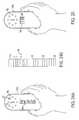
- FIG. 1is a top or plan view of the medical device position guidance system illustrating an intravenous application involving a peripherally inserted central catheter inserted into a human body and illustrating radio wave communication between the catheter assembly and the noninvasive device.
- FIG. 2is a perspective view of the medical device position guidance system illustrating an enteral application involving a catheter inserted into a human body and illustrating communication between the catheter assembly and the noninvasive device.
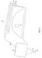
- FIG. 3is an elevated side and schematic view of an embodiment of a catheter assembly communicating with the noninvasive device, where the noninvasive device uses a vertically-oriented output coil.
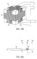
- FIG. 4is a perspective view of the noninvasive device, according to an embodiment.
- FIG. 5is a top view of the noninvasive device, according to an embodiment.
- FIG. 6is a rear view of the noninvasive device, according to an embodiment.
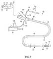
- FIG. 7is a top and schematic view of the enteral catheter assembly, according to an embodiment.
- FIG. 8is an enlarged top view of the enteral catheter illustrating the coil in the bolus of the catheter assembly of FIG. 7 .
- FIG. 9is a schematic view of a catheter assembly having a catheter with an open end.
- FIG. 10is a schematic view of a catheter assembly having a catheter with flapped openings on the sidewalls of the catheter.
- FIG. 11is a schematic view of a catheter assembly having a medical treatment device disposed at an end of the catheter for use in ablation therapy or other types of medical treatment.
- FIG. 12is a schematic view of a catheter assembly having a stent and a balloon at an end of the catheter for use in stenting operations.
- FIG. 13is an enlarged top, schematic view of the noninvasive portion of the catheter assembly.
- FIG. 14Ais a schematic view of the medical device position guidance system illustrating an embodiment where the invasive device and the noninvasive device communicate indirectly with one another through a main processing unit.
- FIG. 14Bis a schematic view of the medical device position guidance system illustrating an embodiment where the invasive device and the noninvasive device communicate indirectly with one another through a main processing unit.
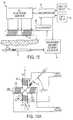
- FIG. 15is a simplified schematic block diagram of one embodiment of a catheter locating system.
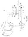
- FIG. 16Ais a schematic diagram of the pair of horizontal field generating coils located over the catheter of the system of FIG. 15 , useful in illustrating the catheter depth determination accomplished by the system of this embodiment.
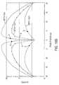
- FIG. 16Bis a graph of sensor coil voltage induced by the pair of horizontal field generating coils of FIGS. 15 and 16A at four different catheter depths as the horizontal field generating coils are moved horizontally along the patient's skin.
- FIG. 17is a view similar to that of FIG. 16A , illustrating the relative horizontal angular orientation of the sensor coil longitudinal axis, the longitudinal axes of the two horizontal field generating coils and the phases of the induced sensor voltages relative to the phases of the respective output coil drive voltages;
- FIG. 18Ais a cross sectional, schematic view of a catheter and one embodiment of the external noninvasive device of this invention that uses a vertically-oriented output coil.
- FIG. 18Bis an alternate form of an output coil set incorporating a vertically-oriented output coil.
- FIG. 19Ais a view of the sensor showing an edge view of the plane which bisects the sensor midpoint.
- FIG. 19Bis a graph of sensor coil output voltage induced by the vertical coil of FIG. 18A versus the distance of the vertical coil from the plane bisecting the sensor coil and perpendicular to the sensor coil longitudinal axis for three different sensor depths.
- FIG. 20is a schematic electronic diagram of the embodiment of the system of this invention.
- FIG. 21is a timing diagram for the circuit of FIG. 20 .
- FIG. 22depicts the multiplexer output for the system of FIG. 20 , showing reference, battery, test sensor and sensor coil voltages.
- FIG. 23is a flow chart illustrating the programming of the microprocessor of FIG. 20 , and the operation of the system of FIG. 20 .
- FIG. 24Ais a top plan view of one form of an noninvasive device for the system of this invention.
- FIG. 24Bis an enlarged view of the distance display of the noninvasive device of FIG. 24A .
- FIG. 25is a top plan view of an alternative design for the noninvasive device of the system of this invention.
- FIG. 1illustrates one embodiment of a medical device position guidance system 500 .
- the medical device position guidance system 500includes an external device or noninvasive device 502 and a catheter assembly 504 .
- the noninvasive device 502is positionable over a surface of an animal, such as a human 506 .
- the illustrated exampledepicts a human, it should be appreciated that medical device position guidance system 500 could be used with any animal such as domestic animals.
- the noninvasive device 502includes a noninvasive housing 508 which supports a magnetic field generator 510 , and a receiver 512 including an antenna 512 a operably coupled to a processor 523 , where the processor 523 is coupled to a memory device 515 .
- the medical device position guidance system 500is operable to provide audiovisual information about the orientation of an invasive medical device and the position of the invasive medical device relative to the external device 502 , through a wireless connection between the invasive medical device 504 and the noninvasive device 502 .
- the magnetic field generator 510includes a plurality of electromagnetic output coils 558 , as illustrated in FIG. 3 .
- the userinserts a predetermined length of the catheter assembly 504 into the patient's blood vessel 532 .
- an outer wall of the catheterincludes markings indicating the length of the catheter 522 that has been inserted.
- the user or medical personnelmoves the noninvasive device 502 over the skin 518 of the human body 506 and powers-on the magnetic field generator 510 to generate a magnetic field.
- the usermoves the noninvasive device 502 to direct the generated magnetic field through the skin 518 of the human body 506 to a location that is proximate to the estimated position of the end or tip 520 of the catheter 522 .
- the receiver 512receives radio wave signals from the transmitter 516 of the catheter assembly 504 , as described in further detail below.
- the receiver 512includes an antenna 512 a , as illustrated in FIG. 1 , to receive radio frequency signals and is connected to a processor 523 that is powered by a battery 521 .
- the catheter assembly 504includes a catheter 522 that is sized and shaped to be inserted into an animal.
- a distal end 528 of the catheter 522may be inserted intravenously as shown in FIG. 1 into a vein, artery or blood vessel 532 of the human body 506 or enterally as shown in FIG. 2 into the gastrointestinal tract.
- the user or medical personnelinserts the distal end 528 of the catheter 522 through the arm vein 532 to a position adjacent to the heart 534 of the body 506 of a patient.
- the catheter assembly 504includes a y-port connector 536 .
- Branched end 542 of the y-port connector 536connects, directly or indirectly, to a fluid source 540 .
- the fluid source 540may be medicine or any other suitable fluid used in intravenous or intravascular medical procedures. It should be appreciated that the branched end 542 of the y-port connector 536 may be closed off by an end cap 546 depending upon the medical procedure that is implemented.
- the branched end 544 of the y-port connector 536is matably connectable through connector 538 to the extension 530 of the catheter 522 .
- the extension 530 of the catheter 522includes a noninvasive portion carrying an antenna 560 , as shown in FIG. 13 , a processor 548 , one or more indicators 550 and a battery 552 .
- the battery 552supplies power to the indicator 550 , the processor 548 and the antenna 560 .
- the catheter assembly 504also includes an elongated conductor 554 connected to the processor 548 which runs through the extension 530 of the catheter 522 , through the connector 538 , through the y-port assembly 536 , and continues to a coil 524 at the distal end 528 of the catheter.
- a styletis operatively connected to the transmitter 516 and includes a tube and a guidewire supported inside the tube.
- the guidewireincludes a steering wire or core wire and an elongated conductor wire.
- the steering wire or core wirehas a stiffness characteristic to facilitate with steering of the tip of the tube through a passageway in an animal.
- the conductor wireis a single wire having a positive end and a negative end, which are positioned adjacent to each other at the proximate end of the core wire. Along the length of the core wire, the ends of the conductor wire are twisted about the core wire to shield or reduce any magnetic fields generated by the conductor wire along the length of the core wire.
- the conductor wireforms a helical coil configured to induce a current when exposed to a magnetic field.
- the core wirealso functions as a grounding device for the antenna 560 of the transmitter 516 , as shown in FIG. 13 . Therefore, the antenna's ground device includes the core wire. In other embodiments, a suitable grounding device is incorporated directly into the antenna.
- the conductor 554includes at least one conductor wire 554 a axially twisted about a relatively stiff guidewire, and these wires function as a stylet, aiding the user in steering the catheter 522 inside the human 506 .
- the coil 524is, in one embodiment, comprised of a helical structure formed by multiple spirals of the distal end 528 of the conductor wire 554 a .
- the coil 524can be a separate wire coil unit which is operatively coupled to the conductor 554 in any suitable fashion.
- the antenna 560 , processor 548 and battery 552can be housed, lodged or otherwise incorporated into the walls of the distal end 528 of the catheter 522 .
- the conductor 554 and the coil 524can be withdrawn through the distal end 528 of the catheter 522 out of the vessel 532 of the patient while the catheter 522 remains inside the patient.
- the userremoves the conductor 554 and sensor coil 524 from the body after the medical device position guidance system 500 assesses the actual or approximate position and orientation of the tip or end 520 of the catheter 522 in the patient.
- fluidcan be introduced from the fluid source 540 or other medical treatment can be performed at the treatment site inside the vessel 532 .
- the user or medical personnelin operation, in an embodiment, as shown in FIG. 1 , the user or medical personnel: (a) inserts a catheter a known or approximate distance into the vessel 532 of the patient; (b) activates the noninvasive device 502 to begin generating the magnetic field; (c) moves the noninvasive device 502 to direct the generated magnetic field 568 as shown in FIG. 3 in the proximity of where the tip 520 of the catheter 522 is estimated to be located; (d) receives an indication from the noninvasive device 502 regarding the relative position and orientation of the catheter tip 520 with respect to the noninvasive device 502 ; and (e) adjusts the position of the noninvasive device 502 or the catheter assembly 504 or both until the user is comfortable with the location of the catheter tip 520 within the vessel 532 .
- the noninvasive device 502includes a main battery 556 that provides a voltage to the plurality of electromagnetic output coils 558 , as illustrated in FIG. 3 , to produce the magnetic field.
- the magnetic fieldpropagates through the tissue or skin 518 of the patient 506 and induces a voltage in the coil 524 .
- the induced voltagetravels through the wire 554 to the processor 548 of the transmitter assembly 558 .
- the processor 548 of the transmitter assembly 558converts the induced voltage and supplies information to the transmitter 516 .
- the transmitter 516wirelessly outputs the information through an antenna 560 as illustrated FIG. 13 in the form of modulated electromagnetic waves or radio waves.
- the frequency of the radio wavesis approximately seventy hertz. However, it should be appreciated that the frequency may be any suitable frequency to allow radio communication between the transmitter and the receiver.
- the radio waveswirelessly travel through the communication channel 564 or atmosphere to an antenna 512 a of the receiver 512 of the noninvasive device 502 .
- the transmitter assembly 558also includes one or more indicators 550 that indicate, upon instruction from the processor 552 , whether the information has been successfully transmitted.
- the indicators 550may also be used to indicate other operating parameters such as battery 552 strength, for example.
- the induced voltage in the coil 524provides information regarding the proximity of the tip 520 of the catheter 522 to the noninvasive device 502 over the surface of the human.
- the induced voltagealso provides information regarding the directional orientation of the tip 520 of the catheter 522 relative to the noninvasive device 504 .
- the receiving processor 523as illustrated in FIG.
- the receiver processor 523receives information, transmitted by the transmitter 516 of the transmitter assembly 558 , and the receiver processor 523 converts this information from a sinusoidal electromagnetic wave having a determined modulated frequency to a series of electrical impulses.
- the receiver processor 523sends these impulses to the main processor 517 through one or more pins within the receiver 512 .
- the main processor 517processes these impulses to cause the indicator 566 of the noninvasive device as illustrated in FIG. 5 to provide visual output in the form of the selection illumination of the directional arrow light sources 578 .
- the arrow lights 578indicate whether the tip 520 is pointed North, East, South, West or in between such directions.
- the main processor 517also causes a speaker 586 to generate a series of variable tones.
- the main processor 517varies the series of tones by frequency, volume or pitch to indicate whether the user is moving the noninvasive device 502 closer to, or further away from, the tip 520 in the human body.
- the indicators 566can include one or more light emitting diodes (LEDs) or display devices, such as liquid crystal display (LCD) panels operable to provide graphics and images related to the position of the tip 520 .
- LEDslight emitting diodes
- LCDliquid crystal display
- the noninvasive device 502is operatively connectable to, and in communication with, the catheter assembly 504 wirelessly through the two antennas 516 and 512 . Therefore, in this embodiment, the noninvasive device 502 , has no lead wires or cables physically connecting the noninvasive device 502 to the catheter assembly 504 .
- the noninvasive device 502can be fully contained within a disposable sterile bag or envelope to protect the patient from contamination that may arise with respect to cross-patient uses of the noninvasive device 502 . Accordingly, the noninvasive device 502 may be reused over a series of procedures with different patients while facilitating sterility. Also, the lack of wires attached to the exterior of the noninvasive device 502 minimizes or reduces the possibility of wires becoming tangled with the medical personnel or other equipment during a medical procedure.
- the receiver 512 of the noninvasive device 502is attachable to the main housing 580 of the noninvasive device 502 as a removable modular unit 582 .
- this modular unit 582includes a dedicated battery 521 as shown in FIG. 3 , and one or more electrical connections to removably connect to corresponding electrical connections located on the main housing 580 .
- the electrical connectionsmay be a multiple pin and socket arrangement.
- the processor 523converts the modulated radio waves received through the antenna 560 , as shown in FIG. 13 into electrical impulses, and the electrical impulses are transmitted through the electrical connectors.
- the electrical impulsesare interpreted by a the main processor 517 housed in the main housing 580 , as illustrated in FIGS. 3 and 4 .
- the main processor 517controls the indicators 566 based on this information.
- the noninvasive device 502includes a power switch 584 , illustrated in FIG. 4 , that activates the battery in the main housing 580 to provide power to the main processor 517 and indicators 566 of the noninvasive device.
- the power switch 584may also activate the secondary battery.
- the modular unit 582may also include a separate power switch to activate the secondary battery.
- the modular unit 582has a plurality of internal walls configured to mate with walls of the main housing 580 in a press-fit connection.
- the usercan convert the noninvasive device 502 between: (a) wireless communication mode in which the device 502 communicates with the catheter assembly 504 through antenna 516 and 512 and (b) a mode in which the device 502 is physically connected to the catheter assembly 504 through a data cable.
- the transmitter assembly 558includes a battery 552 , a processor 548 , an indicator 550 , and a transmitter 516 .
- the transmitter assembly 558also includes a rotatable plug or cap 632 that is operable to electrically connect the battery 552 to the processor 548 .
- the rotatable cap 632includes a threaded connecter that can be screwed onto a portion of the noninvasive housing 508 and has an electrical contact that is movable between: (i) a first position in which the battery 552 is electrically disconnected from the processor 548 ; and (ii) a second position in which the battery 552 is electrically connected to the processor 548 .
- the battery 552is initially in a non-activated state before the catheter assembly 522 has been used and the user screws on the rotatable cap 632 to an end portion 636 of the transmitter assembly 558 to engage the contact 634 with an electrical contact of the processor 548 to allow the battery to provide power to the processor 548 , the indicator 550 and the transmitter 516 .
- the transmitter 516converts the electrical impulses sent through the wire 554 into modulated radio waves and emits the radio waves out through the antenna 560 .
- the electrical contact 634may be a removable insulating film or other suitable device operable to cause the battery circuit to close when the film is removed from the circuit.
- the battery 552is housed in the rotatable cap 632 which can rotate in the opposite direction or be unscrewed to completely remove the battery 552 and the rotatable cap 632 from the catheter assembly 504 .
- the rotatable cap 632facilitates disposal of the battery separate from the catheter assembly.
- the transmitter 516 of catheter assembly 504is configured to communicate indirectly with the receiver 512 of the noninvasive device 502 .
- the transmitter 516transmits radio waves through antenna 560 to a receiver 638 of a central processing unit 640 .
- the receiver 638 of the central processing unit 640converts the modulated radio waves into electrical impulses that are supplied to the processor of the central processing unit 640 .
- the central processing unit 640is a computer having a processor and a display device 644 .
- the display device 644displays information regarding the position and orientation of the medical device in the body of the patient relative to the noninvasive device 502 .
- the central processing unit 640also includes a transmitter 642 to communicate with the receiver 512 of the noninvasive device 502 .
- medical device position guidance system 701includes a noninvasive device 702 and a medical device 704 .
- the medical device 704is configured to communicate indirectly with the noninvasive device 702 through a central processing unit 744 . As shown in FIG. 14B , in an embodiment, medical device position guidance system 701 includes a noninvasive device 702 and a medical device 704 .
- the medical device 704is configured to communicate indirectly with the noninvasive device 702 through a central processing unit 744 . As shown in FIG.
- medical device 704includes: (a) a catheter 722 having an invasive end or tip 720 ; (b) a receiver housing 758 that houses a receiver 716 having an antenna 760 , a battery 748 , a processor 750 , and an indicator 752 ; (c) a conductor 754 supported by the catheter 722 and operatively connected to the receiver 716 ; and (d) an invasive magnetic field generator 724 operatively connected to an invasive distal end 770 of the conductor 724 and powered by the battery 748 .
- the noninvasive device 702includes: (a) a transmitter or transceiver 712 having an antenna 772 ; (b) a battery 780 ; (c) a processor 782 ; (d) an indicator 784 ; and (e) one or more coils 710 operatively connected to the transmitter 712 through the processor 774 .
- the coilsare operable to receive an induced current in response to a magnetic field 768 generated by the magnetic field generator 724 when the magnetic field 768 is directed toward and reaches the coils 710 .
- the coils 710may be any suitable structure or structures capable of receiving a current in response to a generated magnetic field.
- the central processing unit 740includes a display 744 , a transceiver or receiver 742 having an antenna 788 and a transmitter or transceiver 738 having an antenna 790 . It should be appreciated that although the transmitter 738 and receiver 742 are illustrated to be separate components, they may be the same component functioning as a transceiver and sharing an antenna.
- the central processing unit 740causes the transmitter 738 to emit radio waves through the antenna 790 ;
- the receiver 716 of the medical device 704receives the radio waves through the antenna 760 and the processor 750 converts the radio waves to a series of electrical impulses;
- the electrical impulsestravel through the conductor 754 to the magnetic field generator 724 ;
- the magnetic field generator 724generates a magnetic field 768 that passes through the tissue 718 of the animal and induces a current in the coils 710 of the noninvasive device;
- the processor 782converts the induced current to radio waves that are emitted through the antenna 772 of the transmitter 712 ;
- the receiver 742 of the central processing unit 744receives the radio waves through the antenna 788 .
- the display device 744displays information regarding the position, path or shape of path, or orientation of the invasive portion of the medical device 704 in the body of the patient.
- the medical device position guidance system 501is utilized in an enteral application.
- the system 501includes the same components, elements, structure and functionality as system 500 except that system 501 includes enteral catheter 523 and enteral fluid source 541 instead intravascular catheter 522 and intravascular catheter 522 and intravascular fluid source 540 , respectively.
- the enteral catheter 523has a partially rounded end, tip or bolus 521 .
- the bolus 521has a plurality of lowered side walls which define an upper opening. In one embodiment, the bolus 521 defines an additional opening at its end.
- the user or medical personnelpositions the noninvasive device 502 over the skin or tissue 518 of a patient.
- the distal end 528 of the catheter 523is inserted through the mouth and esophagus 572 into the enteral cavity 570 of a patient.
- the branched arm 542 of the y-port connector 536connects to a fluid source 541 such as a feeding bag.
- the medical device position guidance system 501provides the user with audiovisual information to assist in assessing the position of the end or tip 521 of the catheter 523 as described above with respect to the intravascular system 500 .
- the enteral system 501reduces the risk that the catheter may be inadvertently misplaced. Accordingly, the risk of injury to the patient is reduced.
- the multi-port or y-port connector 536includes: (a) a body 594 ; (b) a first branched arm or liquid delivery branch, medicine delivery branch or medicine branch 542 attached to the body 594 for distributing drugs, medicine or other medicinal liquids to the patient; (c) a second branched arm or catheter connection branch 544 attached to the catheter 522 ; (d) a flexible or movable arm 592 attached to the body 594 ; and (f) a flexible or moveable arm 546 attached to the body 594 .
- y-port connector 536includes additional branches for administering various nutrients or medicines to the body.
- the y-port connector 536includes only a feeding branch 542 and a connection branch 544 .
- the arm 546has a stopper 596
- the arm 544has a stopper 598 .
- the stoppers 596 and 598are sized to prevent fluid from passing through the branches 544 and 542 after such branches 544 and 542 are plugged with stoppers 596 and 596 , respectively.
- the arm 544includes a tube-size adapter 600 to the arm 544 .
- the tube-size adapter 600enables fluid delivery tubes (not shown) having various diameters to connect to the feeding branch 544 of the y-port connector 536 .
- the enteral catheter 523includes a feeding tube having: (a) a proximal end 602 attached to the catheter connection branch 544 of the y-port connector 536 ; (b) a distal end 521 ; and (c) an external surface 604 .
- the proximal end 602is insertable into the catheter connection branch 544 of the y-port connector 536 so as to bring the enteral catheter 523 into fluidic communication with the y-port connector 536 .
- the external surface 604has a plurality of volumetric, measurement or unit markings (not shown) uniformly spaced along enteral catheter 523 . These markings assist the user in measuring the flow or distribution of liquid to or from the patient.
- markingsfunction as placement markers which assist the user in assessing the depth that the catheter is placed within the human body.
- the markingsmay be used to make the initial estimation as to where the tip or end 521 of the catheter 523 is within the patient or body. Then the medical device positioning guidance system 500 is used to provide audiovisual information about the position of the tip 521 .
- the conductor 554connects to the coil 524 and runs through the catheter 522 , through the first branched arm 544 of the y-port connector 536 and on to the transmitter assembly 558 .
- the electrical impulses induced in the coil 524are sent along the wire and converted by the transmitter 516 into modulated radio waves.
- the end member, bolus or tip 521is attached to the distal end 606 of the catheter 522 .
- the tip 521includes a body 608 having a collar 610 and an end member 612 .
- the body 608defines a passage 616 and an opening 618 .
- the opening 618is positioned between the collar 610 and the end member 612 .
- a portion 614 of the end member 612can have a rounded shape.
- the shape of the passage 616 and opening 618 of the tip 520is configured to facilitate the flow of fluid from the catheter 522 into the patient's body while decreasing the likelihood that the opening 618 will become clogged.
- the noninvasive device 502 and transmitter assembly 558can be used together in a variety of medical applications.
- the transmitter assembly 558is coupled to a catheter with an opening 618 located on the portion 614 of the end member 612 .
- the end member 520 ais tubular and may be cut such that the opening 618 is circular and defined by the tube diameter.
- the transmitter assembly 558is coupled to a catheter that defines one or more openings 618 located on a sidewall 620 of the end member 520 b .
- the sidewall 620is cut to form flaps 622 that allow fluid to be dispensed to the patient.
- the transmitter assembly 558is coupled to an end member 520 c through a wire 554 .
- the end memberincludes a medical device 624 such as a radio frequency or thermal energy ablation device.
- the medical device 624does not include a catheter, and thus, it not configured to deliver fluid to the patient.
- the coil 524transmits electrical impulses through the wire 554 to the transmitter assembly 558 , as discussed above.
- the transmitter assembly 558is coupled to the end member 520 d through a wire 554 , as discussed above.
- the end member 520 dincludes a stent 624 and a balloon 626 inserted within the stent.
- the medical device position guidance system 500facilitates locating the position of the coil 524 and the stent 626 within the body, as discussed above.
- an operator or medical personnelinflates the balloon 628 by pumping a gas through an air passageway 630 such as a tube.
- the inflation of the 628deploys the stent 626 within a vein or artery of the patient.
- the balloon 628is then deflated and balloon 628 , coil 524 , wire 554 , and air passageway 630 are withdrawn from the vein or artery of the patient.
- the medical device position guidance system 500is operable to assist the placement of any medical device or invasive component into an animal in the course of stent placement, ablation, blockage removal, heat treatment, surgical procedure, fluid delivery or any other suitable invasive procedure. It should be appreciated that any type of catheter may be used for any of the medical procedures described above. It should also be appreciated that any suitable invasive medical device can be used in place of a catheter.
- the noninvasive device 502 and catheter assemblies 522 and 523include the components, elements, structure and functionality described above in addition to the components, elements, structure and functionality of the system 10 described below.
- System 10is used for externally locating a sensor in tissue.
- the sensoris typically an inductive coil placed within a catheter near its tip.
- the system 10also includes an external, noninvasive device which generates electromagnetic fields which penetrate the patient's skin and couple to the sensor coil. The induced sensor coil voltages are detected.
- the sensor coil voltages, and the drive signals used to create the electromagnetic fields in the noninvasive deviceare compared, to assess the distance between the noninvasive device and the sensor coil, the relative angular orientation, in a horizontal plane, between the catheter and the noninvasive device, and to assess when the noninvasive device is directly over, or very close to, a plane bisecting the center of the sensor coil.
- the userthus is able to assess the location of the catheter tip, the depth of the catheter in the body, and the direction in which the catheter tip is pointing. This allows the user to confirm that the catheter tip is in the correct location, and pointing in the correct direction, to assist in proper catheter placement.
- System 10for externally locating a sensor placed in a patient's body.
- System 10includes an noninvasive device which includes pair 12 of perpendicular electromagnetic output coils. Coil pair 12 is moved over skin 7 to detect the depth of, and angular orientation of, inductive sensor coil 30 carried by and proximate the distal end of catheter 9 located under skin 7 .
- the coils of coil pair 12are driven by high frequency signals developed by coil drive voltage generator 2 under control of microprocessor 50 .
- the coil drive voltagesare preferably time-multiplexed to allow a single frequency source in microprocessor 50 to be used to generate the drive signals for both coils.
- a transformeris used to isolate the patient from the input amplifier circuitry.
- the analog output signal of circuit 8is then digitized by analog-to-digital (A/D) converter 48 .
- the digitized signalsare provided to microprocessor 50 , which assesses from these signals, and the drive signals provided to coil drive voltage generator 2 , both the distance between coil set 12 and sensor coil 30 , and the direction D (called the “true direction”) in which the distal end of catheter 9 is pointing.
- the depthis displayed to the operator by depth display 6 .
- the catheter true directionis displayed to the operator by direction display 4 .
- Coil pair 12includes cross-shaped coil form 13 on which are wound perpendicular, coplanar coils 103 and 105 .
- Form 13may be magnetic material or not.
- the longitudinal axis of coil 103lies along an X-axis
- the longitudinal axis of coil 105lies along a Y-axis.
- coil 103will on occasion be referred to as “the X coil”
- coil 105will on occasion be referred to as “the Y coil.”
- Coil set 12is shown as being almost directly above sensor coil 30 of catheter 9 .
- Longitudinal axis X of coil 103is non-parallel to longitudinal axis Y of coil 105 .
- the axesare perpendicular.
- Longitudinal axis B of sensor coil 30lies at an angle A from axis X.
- the direction of the arrowhead on axis Balso indicates the direction in which the distal end of catheter 9 is pointing (the true direction).
- Coils 103 and 105are driven separately by an X drive voltage and Y drive voltage, respectively, generated by coil drive voltage generator 2 , FIG. 15 . Together, coil drive voltage generator 2 and microprocessor 50 shown in FIG. 15 alternately energize coils 103 and 105 .
- the distance determinator shown in FIG. 15includes transformer/amplifier/rectifier/multiplexer 8 , A/D converter 48 , and microprocessor 50 which together assess from the voltage induced in sensor coil 30 the distance between sensor coil 30 and coils 103 and 105 .
- all of the components of system 10are carried by an noninvasive device (not shown).
- Coils 103 and 105are alternately energized to generate a time-varying magnetic field which penetrates a patient's skin.
- the time-varying magnetic fieldis created by first driving X coil 103 , and then driving Y coil 105 with the same high frequency voltage.
- Coils 103 and 105are then again sequentially driven by the same voltage, but reversed in phase in relation to the voltage used to drive the coils the first time.
- This schemecreates a magnetic field whose axis points in sequence to 0°, 90°, 180° and then 270°. This pattern is repeated over and over to create a virtual rotating magnetic field.
- coils 103 and 105are driven alternately by the same drive voltage, without the phase reversal discussed above. This creates a magnetic field whose axis points in sequence to 0°, 90°, 0°, 90°, etc.
- the voltage induced in coil 30is related to both the sensor-to-coil distance, as well as the horizontal angle A of sensor axis B relative to X-coil 103 axis X, and Y-coil 105 axis Y. If Vsx is defined as the voltage induced in sensor coil 30 by the field from coil 103 , and Vsy the coil 30 induced voltage from coil 105 , those values may be determined by the following equations:
- Vsxinduced sensor voltage due to field from X coil
- Vsyinduced sensor voltage due to field from Y coil
- Ahorizontal angle between the projection of the axis of the sensor coil and the projection of the axis of the X coil into a plane parallel to the X and Y coils′ axes
- the vector sum of Vsx and Vsy,is independent of angle A. If this vector sum is labeled Vsh, the following holds true:
- Vsh 2is in itself a quantity independent of angle A, it is not necessary to calculate the square root of the sum of the squares, as is done in equation (3). By not performing the square root calculation, the number of calculations required by microprocessor 50 , FIG. 15 , is reduced, allowing more time for other calculations to be performed by microprocessor 50 .
- Microprocessor 50reads and stores the amplified, rectified Vsx and Vsy voltages, and performs the calculations of equations 1 through 3 to develop Vsh or Vsh 2 . As explained below, microprocessor 50 then puts out digital information to drive depth display 6 .
- FIG. 16Bis a graph of instrument position versus Vsh. Note that the voltage values on the vertical axis are logarithmic. Shown are measurements taken at sensor coil depths below coil pair 12 of 2.5 cm, 5 cm, 10 cm, and 15 cm. These appear from the top to the bottom of FIG. 16B in the order just listed. Coil pair 12 was moved at right angles to the sensor coil longitudinal axis, starting at a position directly over the sensor coil (0 cm), out to 20 cm in either direction from the sensor coil longitudinal axis. As can be seen, the drawing of FIG. 16B illustrates that the induced sensor voltage is maximum when the output coils are directly over the sensor coil. As the coil pair is moved horizontally in a straight line at right angles to the sensor coil axis, the sensor voltage decreases as shown.
- the system of this embodimentassess the true direction D in which the catheter tip is pointing.
- Thisis the direction of arrow B, FIG. 16A , which may be defined in relationship to the direction of axis X or axis Y.
- the direction of sensor coil longitudinal axis B(the true direction) may be defined by angle A between axis B and axis X of coil 103 .
- Microprocessor 50calculates angle A according to the following equation:
- Ais defined as the horizontal angle between sensor axis B and the X-coil axis X.
- Angle Amay lie in any one of the four quadrants defined by the X and Y axes.
- the phase difference between the X coil drive voltage and Vsxis 0 degrees.
- output coil 30is pointing to the negative X side of the Y axis, there is a 180° phase difference between those two voltages.
- the Y coil drive voltage used to drive coil 105and the voltage induced in the sensor coil from the Y coil voltage, are in phase (0 degrees).
- those two voltagesare out of phase (180 degrees).
- the quadrantis assessed, which then fully defines the direction of longitudinal axis B in relation to longitudinal axis X, thus determining the catheter distal end true direction.
- FIG. 18Ais a cross sectional view through a embodiment of the noninvasive device 220 and the catheter 9 including sensor coil 30 , of the system of this embodiment.
- FIG. 18Aintroduces an additional concept of a embodiment of the system of this embodiment.
- Noninvasive device 220includes horizontal coil pair 12 as described above relative to FIGS. 16A and 17 .
- vertically-oriented electromagnetic coil 122which lies along “vertical” longitudinal axis 123 , i.e., an axis transverse to a plane parallel to the axes of coils 103 and 105 .
- FIG. 18Bshows an alternate way of constructing coil set 12 a to incorporate vertically oriented coil 122 a and horizontal coils 103 a and 105 a .
- noninvasive device 220is held so that rounded noninvasive device tip 223 is on or next to the skin surface 221 .
- the noninvasive deviceis moved across surface 221 to locate sensor coil 30 near the distal end of catheter 9 .
- the transmitter 516wirelessly emits radio waves through antenna 560 which are then received by the receiver 512 .
- the receiving processor 523receives information, transmitted by the transmitter 516 of the transmitter assembly 558 , and the receiver processor 523 converts this information from a sinusoidal electromagnetic wave having a determined modulated frequency to a series of electrical impulses.
- the receiver processor 523send these impulses to the main processor 517 through one or more pins within the receiver 512 .
- the main processor 517processes these impulses to cause the indicator 566 of the noninvasive device as illustrated in FIG. 5 to provide visual output. Operator displays 222 mounted in noninvasive device 220 are described in more detail below.
- Vertical coil 122is used to assess when noninvasive device tip 223 is at or very close to plane P shown in FIG. 19A , which bisects sensor coil 30 and is perpendicular to longitudinal axis 124 of sensor coil 30 .
- This embodiment of the systemincludes a sensor coil position determinator for determining, from the vertical output coil drive voltage, and the electrical voltage induced in sensor coil 30 by this vertical coil drive voltage, when the longitudinal axis 123 of vertical coil 122 is proximate plane P. This assesses more exactly the position of sensor coil 30 in relation to noninvasive device 220 . This determination can be made in two ways. The first way is to measure the phase change of the induced sensor voltage.
- the phase of the voltage induced in sensor coil 30changes from 0° (in phase) to 180° (out of phase).
- the two signalsare in phase.
- the signalsare out of phase.
- coil 122is at position 122 b , in which longitudinal axis 123 of coil 122 lies in plane P, there would be no signal.
- the second way to assess the position of sensor coil 30 in relation to noninvasive device 220is to measure the change in amplitude of the induced sensor voltage. It has been found that the amplitude of the induced sensor voltage from the field generated from the vertical coil drops to a minimum, or a null, when the coil is directly over the plane P, (position 122 b ). As shown in FIG. 19B , the induced sensor voltage Vsv drops nearly to 0 when coil 122 is positioned in plane P. At a sensor coil depth of 10 cm, the voltage increases up to approximately 40 millivolts as the vertical coil is moved horizontally along axis 124 , FIG. 19A , approximately 5 cm from plane P.
- the positioning of the vertical coil in relation to the sensor coilcan also be assessed from the sensor coil output voltage.
- Detection of plane Pmay thus be based either on the phase change between the vertical coil drive voltage and the resulting induced sensor voltage, or by detection of the sensor voltage null. Null detection, the embodiment, is described in relation to FIGS. 20 through 23 .
- FIG. 20is an electronic schematic diagram of the embodiment of the system of this embodiment.
- Horizontal output coils 103 and 105are wound on cross shaped core 12 .
- vertically-oriented coil 122are driven sequentially as shown in FIG. 21 .
- Signal Fis a high frequency drive voltage derived by dividing the clock frequency of microprocessor 50 using frequency divider 70 .
- the microprocessor 50 clock frequencyis 2 Mhz
- the sequence of coil drivesis established by the output coil driver means which includes microprocessor 50 , frequency divider 70 , exclusive OR circuit 72 , and amplifiers 74 , 76 , 78 and 80 .
- Microprocessor 50also has control outputs labeled X, Y, and V, shown in FIG. 21 . These control signals are provided to circuit 72 to result in multiplexed high frequency drive signals which are amplified and provided to the appropriate coil as the X coil, Y coil and V coil currents depicted in FIG. 21 . The vertical coil is thus energized after each time that either the X coil or Y coil is energized. The resulting voltages induced in sensor coil 30 are also shown in FIG. 21 . In this example, the sensor voltage induced by the X coil current is larger than that induced by the Y coil current. For other sensor coil directions, the sensor voltage induced by the X coil current may be smaller than or equal to that induced by the Y coil current.
- the induced sensor voltageis coupled through isolation transformer 32 to amplifier 34 , band pass filter 35 , full wave rectifier 36 , low pass filter 38 , and DC amplifier 40 .
- Zero adjustment 39ensures that the output of amplifier 40 is 0 volts when the sensor is positioned remotely from all three of the output coils, at a point where virtually 0 voltage is induced in the sensor.
- the output of amplifier 40is connected to multiplexer 46 , whose timing is controlled by signals M 1 and M 2 from microprocessor 50 .
- the multiplexing schemeis described below in conjunction with FIG. 23 .
- the multiplexer outputis connected to amplifier 47 which has a gain of 1. These components make up transformer/amplifier/rectifier/multiplexer circuit 8 a .
- the rectified, filtered output signal of amplifier 40is shown in the lowermost graph of FIG. 21 .
- the multiplexeris preferably timed to connect the amplifier 40 output voltage to amplifier 47 and then on to A/D converter 48 for the greater part of the measurement cycle.
- Multiplexer 46is periodically connected to the battery voltage Vbat and precision DC voltage reference Vref, and to test sensor voltage Vts. In one embodiment, these three voltages are measured in sequence, once per second over three consecutive operating cycles. If the battery voltage Vbat drops below a predetermined threshold, microprocessor 50 is programmed to turn on a low battery indicator light. If the precision voltage reference Vref source changes value beyond a small tolerance, the microprocessor is preferably programmed to turn the instrument off.
- Test sensor 130consists of a small inductive coil positioned adjacent to all three output coils. Typically, but not necessarily, its longitudinal axis is at a 45° angle to the longitudinal axes of all three output coils.
- the fields from each of the three output coilsinduce voltages in the test sensor which are amplified, rectified and filtered by amplifier 132 , rectifier 134 , and low pass filter 136 , respectively.
- the resulting voltage Vtsis periodically read by microprocessor 50 . If an output coil should break, or if the coil drive current should fail or decrease beyond a preset limit, the test sensor output voltage Vts would change accordingly.
- the microprocessoris programmed to sense this and turn the instrument off such that the instrument is on only when functioning properly.
- the digital output of A/D converter 48is connected to microprocessor 50 .
- Microprocessor 50is programmed to store the three voltage levels Vsx, Vsy and Vsv and perform the appropriate calculations to assess the sensor depth (distance from output coils 103 and 105 to sensor coil 30 ) and the true direction determined from angle A, FIGS. 16A and 17 , as described above.
- the calculated valuesare then displayed as outputs to the operator.
- the forms of the outputsare shown in FIG. 6 and also FIGS. 24A through 25 .
- Data establishing the sensor depthmay be provided on four data lines to both decoder driver 52 and binary to seven-segment decoder driver 62 .
- Driver 52is enabled to drive light bar display 48 , which may indicate the strength of the induced sensor voltage Vsh, shown in FIG. 16B .
- light bar display 48 amay be mounted on the upper surface of hand held noninvasive device 220 a and include a number of segments which are typically LEDs with a scale of centimeters alongside.
- the minimum distancewhich corresponds to the peak signal strength, is in one embodiment, continuously updated and the corresponding LED lit, along with the LED representing the currently-sensed distance, to give the operator a better idea of when the noninvasive device is closest to or directly over the sensor coil.
- numerical display 66also shown as display 66 a , FIG. 25 , may be used to indicate the depth directly in inches or centimeters.
- the systemconverts Vsh (or Vsh 2 ) to distance by using the value of the variable to address a distance lookup table in microprocessor 50 , FIG. 20 .
- the lookup tablestores numbers which convert to the depth (in inches, centimeters, or audio frequency).
- Microprocessor 50may also produce a variable frequency which is related to the induced sensor voltage and which is used to drive amplifier 42 , which drives speaker 44 through volume control 43 . This provides a tone whose frequency changes relative to the induced sensor voltage.
- Direction display 78 in this embodimentconsists of eight LEDs arranged in a circle as shown in FIG. 24A as direction display 78 a . These LEDs are driven by decoder-driver 76 , which converts digital information from microprocessor 50 to energize the appropriate direction-indicating LED such as LED 227 , FIG. 24A .
- This direction displayindicates that the distal end of the catheter is pointing in the direction of LED 227 . This is the true direction in which the catheter distal end is pointing. This information is derived from the determination of angle A as described above in conjunction with FIGS. 24 and 27 .
- FIG. 23is a flow diagram of the embodiment of the program resident in microprocessor 50 , detailing the steps used to drive the three output coils, collect the sensor voltage level, make the necessary calculations and comparisons, and drive the audible and visual displays described above.
- Start step 300initializes all the storage registers and timers to zero, or to appropriate start up values.
- multiplexer 46is set by microprocessor 50 to select the reference DC voltage reference V REF , and then select the amplified, rectified output of test sensor 130 , Vts, and sequentially connect the voltages to A/D converter 48 shown in FIG. 20 . If the values of the two voltages fall within preset limits, operation continues to step 302 . Otherwise, a failure is indicated by alternately flashing the ON LED and the BATT.LOW LED for 15 seconds. The instrument is then shut off.
- multiplexer 46is connected by microprocessor 50 to the battery voltage Vbat. If Vbat is below a preset level, a low battery indicator, or LED, is activated by microprocessor 50 . Operation would then continue to step 303 .
- microprocessor 50selects line X shown in FIG. 20 to drive X coil 105 .
- Multiplexer 46is enabled to select the amplified and rectified induced sensor voltage at the output of amplifier 40 , which is digitized and stored in the memory of microprocessor 50 .
- Steps 304 , 305 and 306repeat the process for the vertical coil by selecting line V out of the microprocessor 50 , the Y coil by selecting line Y out of the microprocessor 50 , and the vertical coil a second time, respectively.
- step 307the signals induced by the X and Y coils are squared and summed by microprocessor 50 to produce a value which is based on the strength of the X and Y fields at the sensor, regardless of the sensor-to-output coil horizontal angle.
- step 308microprocessor 50 outputs from its lookup table digital information to drive decoder drivers 52 and 62 using the calculation as described above.
- step 309microprocessor 50 converts the values derived in step 307 to a variable frequency tone which drives speaker 44 .
- Steps 310 through 317are the sensor coil location determination and direction display steps.
- microprocessor 50reads the value of the sensor coil voltage induced by the field generated from vertical output coil 122 .
- Step 311constitutes the microprocessor null detection subroutine for detecting the null in the output as shown in FIG. 19B .
- the microprocessorperiodically reads and stores the peak value of the sensor voltage induced by the field from vertical output coil 122 .
- Microprocessor 50has established therein a threshold value which is a specific percentage of the peak vertical induced voltage. Typically, this threshold is set as 1 ⁇ 4 of the peak voltage. Since the peak is continuously refreshed, this threshold may change. When the sensed voltage drops below this threshold, the microprocessor enters a second state—called state 2.
- step 311After entering into the second state, if the vertical induced voltage again rises above the threshold by a predetermined amount, for example 50% above the threshold, state 3 is entered in step 311 . If state 3 is entered, at step 312 the value of Vsh 2 is read. If the sensor-to-output coil distance determined from Vsh 2 is greater than a preset value (in this case 18 cm) the direction display is inhibited. This prevents the direction calculation from being based on weak induced signals which may have a large noise component and thus be inaccurate. In step 313 , the microprocessor determines whether Vsh 2 exceeds the peak value of Vsh 2 divided by 4.
- a preset valuein this case 18 cm
- the tangent of angle Ais calculated, step 314 , the quadrant into which the sensor coil is pointing is determined, step 315 , the appropriate direction-indicating LED is lit, step 316 , and a “sensor found” audible beep is generated, step 317 .
- the direction calculationis performed only when the Vsv null has been detected (state 3). This is such that the TangentA is calculated only when the XY output coil pair is closest to the sensor and at or near the plane of the sensor midpoint. This is where the tangent calculation is the most accurate.
- noninvasive device 220which contains vertical coil 122 , is moved back and forth relatively quickly while held at about 15 to 20 cm horizontally removed from the bisecting plane, at which there is a relative null in voltage V SV , a false null may be simulated. That is, the voltage V SV can drop below the threshold and then rise again a percentage above the threshold.
- microprocessor 50is preferably programmed to require state 3 to occur within a specific required time interval after state 2 is entered, or else null detection is inhibited.
- This state 2 to state 3 time intervalis preferably variable with the strength of the peak voltage.
- the peak signalis weak and the null is wide. That is, the voltage drops off relatively gradually as the vertical coil approaches plane P. In that case, a relatively long time interval is needed to allow the operator to move the instrument a sufficient distance to reach state 3.
- the nullbecomes sharp and narrow. That is, the voltage drops off very rapidly when the output coil is very close to plane P. In this case, since the distance the noninvasive device must traverse to reach state 3 is small, the time interval can be short.
- FIG. 19Billustrates this concept for three different catheter depths.
- the noninvasive devicemust move from point A to point B to enter state 3. This equates to a distance of approximately 3 cm. If the noninvasive device is typically moved at 10 cm per second, the time interval to reach state 3 should be at least 0.3 seconds.
- the distance from point C to point Dis about 7 cm, which requires 0.7 seconds.
- the time intervalshould be at least 0.7 seconds.
- the time interval after state 2 is entered in which state 3 must be enteredis preferably variable from about 0.15 to about 1.0 seconds. This time interval may be established by software in the microprocessor according to the peak value of Vsv using a lookup table.
- the stored peak values of Vsh 2 and Vsvare preferably made to decay at a specific time constant, typically between 0.3 and 2.0 seconds. Decaying the Vsv peak helps to reduce false null determinations by continuously reducing the threshold values at distances remote from the sensor. If the decay time constant is too short, null detection can be inhibited if the operator is moving the instrument too slowly. If the decay constant is too long, false nulls can be indicated, if the operator moves the instrument back and forth at a horizontal distance of perhaps 15 to 20 cm from the sensor coil.
- the Vsh 2 peakis also decayed in a similar manner such that null detection will not be inhibited if the operator should move the instrument slightly farther vertically from the sensor, thereby reducing Vsv while the same threshold voltage is maintained.
- the noninvasive device 502is able to communicate with the catheter assembly 504 through a changing magnetic field and also receive information relating the induced magnetic field in the coil 524 . Therefore, the noninvasive device 502 , which, in one embodiment, has no connecting wires or power cords, may be at least temporarily contained within a sterile bag or sheet (not shown) to protect the patient from substantial contamination that may exist with respect to the noninvasive device. Accordingly, the noninvasive device may be reused over a series of procedures with different patients while still facilitating a substantially sterile environment. Also, the lack of wires attached to the external housing of the noninvasive device 502 reduces the likelihood of wires becoming tangled with the medical personnel or other equipment during a medical procedure.
Landscapes
- Health & Medical Sciences (AREA)
- Life Sciences & Earth Sciences (AREA)
- Engineering & Computer Science (AREA)
- Animal Behavior & Ethology (AREA)
- General Health & Medical Sciences (AREA)
- Public Health (AREA)
- Veterinary Medicine (AREA)
- Physics & Mathematics (AREA)
- Biophysics (AREA)
- Pathology (AREA)
- Biomedical Technology (AREA)
- Heart & Thoracic Surgery (AREA)
- Medical Informatics (AREA)
- Molecular Biology (AREA)
- Surgery (AREA)
- Human Computer Interaction (AREA)
- Pulmonology (AREA)
- Otolaryngology (AREA)
- Media Introduction/Drainage Providing Device (AREA)
- Radar Systems Or Details Thereof (AREA)
Abstract
Description
Claims (3)
Priority Applications (3)
| Application Number | Priority Date | Filing Date | Title |
|---|---|---|---|
| US11/530,385US8197494B2 (en) | 2006-09-08 | 2006-09-08 | Medical device position guidance system with wireless connectivity between a noninvasive device and an invasive device |
| PCT/US2007/077872WO2008031025A2 (en) | 2006-09-08 | 2007-09-07 | Medical device position guidance system with wireless connectivity between a noninvasive device and an invasive device |
| US13/472,588US9687174B2 (en) | 2006-09-08 | 2012-05-16 | Medical device position guidance system with wireless connectivity between a noninvasive and an invasive device |
Applications Claiming Priority (1)
| Application Number | Priority Date | Filing Date | Title |
|---|---|---|---|
| US11/530,385US8197494B2 (en) | 2006-09-08 | 2006-09-08 | Medical device position guidance system with wireless connectivity between a noninvasive device and an invasive device |
Related Child Applications (1)
| Application Number | Title | Priority Date | Filing Date |
|---|---|---|---|
| US13/472,588ContinuationUS9687174B2 (en) | 2006-09-08 | 2012-05-16 | Medical device position guidance system with wireless connectivity between a noninvasive and an invasive device |
Publications (2)
| Publication Number | Publication Date |
|---|---|
| US20080097475A1 US20080097475A1 (en) | 2008-04-24 |
| US8197494B2true US8197494B2 (en) | 2012-06-12 |
Family
ID=39158089
Family Applications (2)
| Application Number | Title | Priority Date | Filing Date |
|---|---|---|---|
| US11/530,385Active2031-01-16US8197494B2 (en) | 2006-09-08 | 2006-09-08 | Medical device position guidance system with wireless connectivity between a noninvasive device and an invasive device |
| US13/472,588ActiveUS9687174B2 (en) | 2006-09-08 | 2012-05-16 | Medical device position guidance system with wireless connectivity between a noninvasive and an invasive device |
Family Applications After (1)
| Application Number | Title | Priority Date | Filing Date |
|---|---|---|---|
| US13/472,588ActiveUS9687174B2 (en) | 2006-09-08 | 2012-05-16 | Medical device position guidance system with wireless connectivity between a noninvasive and an invasive device |
Country Status (2)
| Country | Link |
|---|---|
| US (2) | US8197494B2 (en) |
| WO (1) | WO2008031025A2 (en) |
Cited By (74)
| Publication number | Priority date | Publication date | Assignee | Title |
|---|---|---|---|---|
| US20090306728A1 (en)* | 2004-01-12 | 2009-12-10 | Calypso Medical Technologies, Inc. | Methods and apparatus for stimulating and/or sensing neurons in a patient |
| US20090319013A1 (en)* | 2008-05-19 | 2009-12-24 | Boling C Lance | Implantable neural stimulation electrode assemblies and methods for stimulating spinal neural sites |
| US20100145337A1 (en)* | 2007-02-28 | 2010-06-10 | Smith & Nephew, Inc. | Instrumented orthopaedic implant for identifying a landmark |
| US20100152566A1 (en)* | 2007-02-28 | 2010-06-17 | Smith & Nephew, Inc. | System and method for identifying a landmark |
| US20110319751A1 (en)* | 2007-05-31 | 2011-12-29 | General Electric Company | Dynamic reference method and system for use with surgical procedures |
| US20120083856A1 (en)* | 2010-09-30 | 2012-04-05 | Nevro Corporation | Systems and methods for positioning implanted devices in a patient |
| US20120083702A1 (en)* | 2010-10-01 | 2012-04-05 | Angiodynamics, Inc. | Method for Locating a Catheter Tip Using Audio Detection |
| USD674093S1 (en) | 2009-08-26 | 2013-01-08 | Smith & Nephew, Inc. | Landmark identifier for targeting a landmark of an orthopaedic implant |
| US8623023B2 (en) | 2009-04-27 | 2014-01-07 | Smith & Nephew, Inc. | Targeting an orthopaedic implant landmark |
| US8676331B2 (en) | 2012-04-02 | 2014-03-18 | Nevro Corporation | Devices for controlling spinal cord modulation for inhibiting pain, and associated systems and methods, including controllers for automated parameter selection |
| USD704841S1 (en) | 2009-08-26 | 2014-05-13 | Smith & Nephew, Inc. | Landmark identifier for targeting an orthopaedic implant |
| US8784425B2 (en) | 2007-02-28 | 2014-07-22 | Smith & Nephew, Inc. | Systems and methods for identifying landmarks on orthopedic implants |
| US8805519B2 (en) | 2010-09-30 | 2014-08-12 | Nevro Corporation | Systems and methods for detecting intrathecal penetration |
| US8890511B2 (en) | 2011-01-25 | 2014-11-18 | Smith & Nephew, Inc. | Targeting operation sites |
| US8945147B2 (en) | 2009-04-27 | 2015-02-03 | Smith & Nephew, Inc. | System and method for identifying a landmark |
| US9168153B2 (en) | 2011-06-16 | 2015-10-27 | Smith & Nephew, Inc. | Surgical alignment using references |
| US9220514B2 (en) | 2008-02-28 | 2015-12-29 | Smith & Nephew, Inc. | System and method for identifying a landmark |
| US9339285B2 (en) | 2013-03-12 | 2016-05-17 | Levita Magnetics International Corp. | Grasper with magnetically-controlled positioning |
| US9403020B2 (en) | 2008-11-04 | 2016-08-02 | Nevro Corporation | Modeling positions of implanted devices in a patient |
| US9409020B2 (en) | 2014-05-20 | 2016-08-09 | Nevro Corporation | Implanted pulse generators with reduced power consumption via signal strength/duration characteristics, and associated systems and methods |
| US9526441B2 (en) | 2011-05-06 | 2016-12-27 | Smith & Nephew, Inc. | Targeting landmarks of orthopaedic devices |
| US9539037B2 (en) | 2010-06-03 | 2017-01-10 | Smith & Nephew, Inc. | Orthopaedic implants |
| US9789321B2 (en) | 2015-04-03 | 2017-10-17 | Nevro Corp. | Couplings for implanted leads and external stimulators, and associated systems and methods |
| US9844391B2 (en) | 2009-02-06 | 2017-12-19 | Levita Magnetics International Corp. | Remote traction and guidance system for mini-invasive surgery |
| US9919165B2 (en) | 2014-05-07 | 2018-03-20 | Varian Medical Systems, Inc. | Systems and methods for fiducial to plan association |
| US10010370B2 (en) | 2013-03-14 | 2018-07-03 | Levita Magnetics International Corp. | Magnetic control assemblies and systems therefor |
| US10043284B2 (en) | 2014-05-07 | 2018-08-07 | Varian Medical Systems, Inc. | Systems and methods for real-time tumor tracking |
| US10300277B1 (en) | 2015-12-14 | 2019-05-28 | Nevro Corp. | Variable amplitude signals for neurological therapy, and associated systems and methods |
| US10537348B2 (en) | 2014-01-21 | 2020-01-21 | Levita Magnetics International Corp. | Laparoscopic graspers and systems therefor |
| US10603117B2 (en) | 2017-06-28 | 2020-03-31 | Ethicon Llc | Articulation state detection mechanisms |
| US10751117B2 (en) | 2016-09-23 | 2020-08-25 | Ethicon Llc | Electrosurgical instrument with fluid diverter |
| US10751109B2 (en) | 2014-12-22 | 2020-08-25 | Ethicon Llc | High power battery powered RF amplifier topology |
| US10779876B2 (en) | 2011-10-24 | 2020-09-22 | Ethicon Llc | Battery powered surgical instrument |
| US10799284B2 (en) | 2017-03-15 | 2020-10-13 | Ethicon Llc | Electrosurgical instrument with textured jaws |
| US10856934B2 (en) | 2016-04-29 | 2020-12-08 | Ethicon Llc | Electrosurgical instrument with electrically conductive gap setting and tissue engaging members |
| US10905511B2 (en) | 2015-04-13 | 2021-02-02 | Levita Magnetics International Corp. | Grasper with magnetically-controlled positioning |
| US10959806B2 (en) | 2015-12-30 | 2021-03-30 | Ethicon Llc | Energized medical device with reusable handle |
| US10959771B2 (en) | 2015-10-16 | 2021-03-30 | Ethicon Llc | Suction and irrigation sealing grasper |
| US10980999B2 (en) | 2017-03-09 | 2021-04-20 | Nevro Corp. | Paddle leads and delivery tools, and associated systems and methods |
| US10987156B2 (en) | 2016-04-29 | 2021-04-27 | Ethicon Llc | Electrosurgical instrument with electrically conductive gap setting member and electrically insulative tissue engaging members |
| US20210153724A1 (en)* | 2017-08-29 | 2021-05-27 | Joimax Gmbh | Detection system and method for automatic detection of surgical instruments |
| US11022421B2 (en) | 2016-01-20 | 2021-06-01 | Lucent Medical Systems, Inc. | Low-frequency electromagnetic tracking |
| US11020137B2 (en) | 2017-03-20 | 2021-06-01 | Levita Magnetics International Corp. | Directable traction systems and methods |
| US11027096B2 (en) | 2017-08-21 | 2021-06-08 | Lucent Medical Systems, Inc. | Flexible circuit bearing a trackable low-frequency electromagnetic coil |
| US11033323B2 (en) | 2017-09-29 | 2021-06-15 | Cilag Gmbh International | Systems and methods for managing fluid and suction in electrosurgical systems |
| US11033325B2 (en) | 2017-02-16 | 2021-06-15 | Cilag Gmbh International | Electrosurgical instrument with telescoping suction port and debris cleaner |
| US11058875B1 (en) | 2018-09-19 | 2021-07-13 | Nevro Corp. | Motor function in spinal cord injury patients via electrical stimulation, and associated systems and methods |
| US11090103B2 (en) | 2010-05-21 | 2021-08-17 | Cilag Gmbh International | Medical device |
| US11234769B2 (en) | 2018-03-02 | 2022-02-01 | Lucent Medical Systems, Inc. | Wireless electromagnetic navigational element |
| US11413026B2 (en) | 2007-11-26 | 2022-08-16 | Attractive Surgical, Llc | Magnaretractor system and method |
| US11420045B2 (en) | 2018-03-29 | 2022-08-23 | Nevro Corp. | Leads having sidewall openings, and associated systems and methods |
| US11426133B2 (en) | 2018-03-13 | 2022-08-30 | Lucent Medical Systems, Inc. | Externally placed electromagnetic fiducial element |
| US11474310B2 (en)* | 2020-02-28 | 2022-10-18 | Bard Access Systems, Inc. | Optical connection systems and methods thereof |
| US11484358B2 (en) | 2017-09-29 | 2022-11-01 | Cilag Gmbh International | Flexible electrosurgical instrument |
| US11490951B2 (en) | 2017-09-29 | 2022-11-08 | Cilag Gmbh International | Saline contact with electrodes |
| US11497546B2 (en) | 2017-03-31 | 2022-11-15 | Cilag Gmbh International | Area ratios of patterned coatings on RF electrodes to reduce sticking |
| US11583354B2 (en) | 2015-04-13 | 2023-02-21 | Levita Magnetics International Corp. | Retractor systems, devices, and methods for use |
| US11590352B2 (en) | 2019-01-29 | 2023-02-28 | Nevro Corp. | Ramped therapeutic signals for modulating inhibitory interneurons, and associated systems and methods |
| US11590320B2 (en) | 2019-04-04 | 2023-02-28 | Avent, Inc. | Two-in-one catheter and signal generating apparatus |
| US11633604B2 (en) | 2018-01-30 | 2023-04-25 | Nevro Corp. | Efficient use of an implantable pulse generator battery, and associated systems and methods |
| US11744647B2 (en) | 2017-11-08 | 2023-09-05 | Teleflex Medical Incorporated | Wireless medical device navigation systems and methods |
| US11899249B2 (en) | 2020-10-13 | 2024-02-13 | Bard Access Systems, Inc. | Disinfecting covers for functional connectors of medical devices and methods thereof |
| US11931179B2 (en) | 2020-03-30 | 2024-03-19 | Bard Access Systems, Inc. | Optical and electrical diagnostic systems and methods thereof |
| US11957342B2 (en) | 2021-11-01 | 2024-04-16 | Cilag Gmbh International | Devices, systems, and methods for detecting tissue and foreign objects during a surgical operation |
| US20240181203A1 (en)* | 2021-04-02 | 2024-06-06 | University Of Washington | Systems and Methods for Clearing Indwelling Catheters |
| US12089815B2 (en) | 2022-03-17 | 2024-09-17 | Bard Access Systems, Inc. | Fiber optic medical systems and devices with atraumatic tip |
| US12220219B2 (en) | 2020-11-24 | 2025-02-11 | Bard Access Systems, Inc. | Steerable fiber optic shape sensing enabled elongated medical instrument |
| US12232818B2 (en) | 2020-03-03 | 2025-02-25 | Bard Access Systems, Inc. | System and method for optic shape sensing and electrical signal conduction |
| US12246139B2 (en) | 2020-02-28 | 2025-03-11 | Bard Access Systems, Inc. | Catheter with optic shape sensing capabilities |
| US12262971B2 (en) | 2016-01-08 | 2025-04-01 | Levita Magnetics International Corp. | One-operator surgical system and methods of use |
| US12285572B2 (en) | 2020-11-18 | 2025-04-29 | Bard Access Systems, Inc. | Optical-fiber stylet holders and methods thereof |
| US12318149B2 (en) | 2022-03-08 | 2025-06-03 | Bard Access Systems, Inc. | Medical shape sensing devices and systems |
| US12426956B2 (en) | 2022-03-16 | 2025-09-30 | Bard Access Systems, Inc. | Medical system and method for monitoring medical device insertion and illumination patterns |
| US12440676B2 (en) | 2023-08-18 | 2025-10-14 | Nevro Corp. | Implanted pulse generators with reduced power consumption via signal strength/duration characteristics, and associated systems and methods |
Families Citing this family (21)
| Publication number | Priority date | Publication date | Assignee | Title |
|---|---|---|---|---|
| US8078274B2 (en) | 2003-02-21 | 2011-12-13 | Dtherapeutics, Llc | Device, system and method for measuring cross-sectional areas in luminal organs |
| US10172538B2 (en) | 2003-02-21 | 2019-01-08 | 3Dt Holdings, Llc | Body lumen junction localization |
| US10413211B2 (en) | 2003-02-21 | 2019-09-17 | 3Dt Holdings, Llc | Systems, devices, and methods for mapping organ profiles |
| US7818053B2 (en) | 2003-02-21 | 2010-10-19 | Dtherapeutics, Llc | Devices, systems and methods for plaque type determination |
| US7938846B2 (en)* | 2007-06-22 | 2011-05-10 | Radi Medical Systems Ab | Femoral compression device |
| US8337517B2 (en)* | 2007-12-18 | 2012-12-25 | Eye Care And Cure Pte. Ltd | Surgical apparatus |
| US10172669B2 (en) | 2009-10-09 | 2019-01-08 | Ethicon Llc | Surgical instrument comprising an energy trigger lockout |
| US10624553B2 (en)* | 2009-12-08 | 2020-04-21 | Biosense Webster (Israel), Ltd. | Probe data mapping using contact information |
| US10159531B2 (en) | 2012-04-05 | 2018-12-25 | C. R. Bard, Inc. | Apparatus and methods relating to intravascular positioning of distal end of catheter |
| US11759268B2 (en) | 2012-04-05 | 2023-09-19 | C. R. Bard, Inc. | Apparatus and methods relating to intravascular positioning of distal end of catheter |
| JP2015516846A (en) | 2012-04-05 | 2015-06-18 | バード・アクセス・システムズ,インコーポレーテッド | Device and system for navigating and positioning a central venous catheter within a patient |
| US9351687B2 (en)* | 2012-06-28 | 2016-05-31 | Volcano Corporation | Intravascular devices, systems, and methods |
| US9968269B1 (en)* | 2012-08-31 | 2018-05-15 | Louis O. Noce | Wireless disposable angioplasty transducer manifold |
| WO2016040394A1 (en)* | 2014-09-08 | 2016-03-17 | C. R. Bard, Inc. | Apparatus and methods relating to intravascular positioning of distal end of catheter |
| US10966629B2 (en)* | 2014-12-01 | 2021-04-06 | Koninklijke Philips N.V. | Virtually-oriented electromagnetic tracking coil for catheter based navigation |
| US10314638B2 (en) | 2015-04-07 | 2019-06-11 | Ethicon Llc | Articulating radio frequency (RF) tissue seal with articulating state sensing |
| EP3307157B1 (en)* | 2015-06-12 | 2025-03-05 | Koninklijke Philips N.V. | Catheter for an electromagnetic tracking system |
| US11779391B2 (en)* | 2019-02-28 | 2023-10-10 | Biosense Webster (Israel) Ltd. | Forming a lesion based on pre-determined amount of abaltive energy vs lesion size curve |
| CN112206400B (en)* | 2019-07-12 | 2025-02-28 | 巴德阿克塞斯系统股份有限公司 | Catheter tracking and placement system including a light emitting diode array |
| CN110787360B (en)* | 2019-12-09 | 2020-12-29 | 南通市第一人民医院 | A device for applying medicine to a patient |
| US12144488B2 (en)* | 2021-01-14 | 2024-11-19 | Covidien Lp | Magnetically controlled power button and gyroscope external to the lung used to measure orientation of instrument in the lung |
Citations (201)
| Publication number | Priority date | Publication date | Assignee | Title |
|---|---|---|---|---|
| US921368A (en) | 1908-01-30 | 1909-05-11 | William E Crook | Hose-coupling. |
| US1074706A (en) | 1913-03-22 | 1913-10-07 | Gilbert Jerome Ferguson | Pipe-coupling. |
| US2103050A (en) | 1936-02-26 | 1937-12-21 | Hoover Co | Dusting tool for suction cleaners |
| US2321355A (en) | 1942-01-15 | 1943-06-08 | Waugh Equipment Co | Surgical probe for locating foreign metal particles in body tissue |
| US2521745A (en) | 1949-06-27 | 1950-09-12 | Pope Claude Eugene | Apparatus and method for locating pipes |
| US2820959A (en) | 1956-03-05 | 1958-01-21 | Standard Oil Co | Pipeline scraper-locator transmitter |
| US2863458A (en) | 1957-09-04 | 1958-12-09 | Michael T Modny | Vein stripper and a method of stripping veins |
| US2906944A (en) | 1955-05-16 | 1959-09-29 | Schlumberger Well Surv Corp | Methods for investigating wells |
| US2908863A (en) | 1955-02-18 | 1959-10-13 | Robert J Neff | Electronic locator |
| US2941822A (en) | 1957-08-26 | 1960-06-21 | Whirlpool Co | Vacuum cleaner |
| US2949910A (en) | 1957-03-29 | 1960-08-23 | James R Brown | Phonocardiac catheter |
| US3042030A (en) | 1958-11-25 | 1962-07-03 | Read Thane | Spherical type insert plug for body passageway and tool therefor |
| US3043309A (en) | 1959-09-29 | 1962-07-10 | Avco Corp | Method of performing intestinal intubation |
| US3190290A (en) | 1962-02-08 | 1965-06-22 | Brunswick Corp | Intercostal catheters |
| US3253588A (en) | 1962-02-01 | 1966-05-31 | Lear Siegler Inc | Bio-instrumentation apparatus |
| US3452742A (en) | 1966-05-31 | 1969-07-01 | Us Catheter & Instr Corp | Controlled vascular curvable spring guide |
| US3471773A (en) | 1967-12-20 | 1969-10-07 | Electronic Sensing Prod Inc | Metal detecting device with inductively coupled coaxial transmitter and receiver coils |
| US3547103A (en) | 1965-10-29 | 1970-12-15 | William A Cook | Coil spring guide |
| US3597680A (en) | 1968-12-19 | 1971-08-03 | Aqua Tronics Inc | Method and apparatus utilizing a transmitter and receiver for detecting the presence of a metallic object within a pipe |
| US3605750A (en) | 1969-04-07 | 1971-09-20 | David S Sheridan | X-ray tip catheter |
| US3617865A (en) | 1968-05-25 | 1971-11-02 | Goroku Hakata | Method and apparatus for locating a buried metallic line employing magnetic field gradient measurements |
| US3618614A (en) | 1969-05-06 | 1971-11-09 | Scient Tube Products Inc | Nontoxic radiopaque multiwall medical-surgical tubings |
| US3623101A (en) | 1968-07-11 | 1971-11-23 | Amp Inc | Rf position-sensing and control system |
| US3622784A (en) | 1969-10-29 | 1971-11-23 | Louis R M Del Guercio | Sensor-analyzer system with means for selecting output signals corresponding to accurately positioned sensors |
| US3625200A (en) | 1969-08-26 | 1971-12-07 | Us Catheter & Instr Corp | Controlled curvable tip member |
| US3645562A (en) | 1970-03-10 | 1972-02-29 | Matthew R Fandetti | Coupling device |
| US3653050A (en) | 1969-12-29 | 1972-03-28 | Goldak Co Inc The | Pipe locator method and apparatus |
| US3656161A (en) | 1969-12-31 | 1972-04-11 | Bell Telephone Labor Inc | Maintaining a circularly polarized magnetic field at a moving point |
| US3659588A (en) | 1970-04-08 | 1972-05-02 | Medtronic Inc | Catheter apparatus |
| US3661148A (en) | 1970-04-13 | 1972-05-09 | Univ California | Induction type artery gage |
| US3667781A (en) | 1970-06-26 | 1972-06-06 | Medical Dev Corp | Connector means for flexible conduit |
| US3731684A (en) | 1971-04-08 | 1973-05-08 | Cenco Medical Health Supply Co | Closed irrigation and urinary drainage system apparatus |
| US3749086A (en) | 1972-07-24 | 1973-07-31 | Medical Evaluation Devices & I | Spring guide with flexible distal tip |
| US3749134A (en) | 1972-02-02 | 1973-07-31 | Sunlite Plastics Inc | Radiographically opaque plastic tubing |
| US3794041A (en) | 1971-11-30 | 1974-02-26 | Yeda Res & Dev | Gastrointestinal catheter |
| US3831086A (en) | 1973-11-28 | 1974-08-20 | Bell Telephone Labor Inc | Apparatus for identifying and tracing a pair of conductors |
| US3932805A (en) | 1973-02-02 | 1976-01-13 | Kichizo Niwa | Method of obtaining internal information of a measuring target from the out-side by the application of a nuclear magnetic resonance phenomenon |
| DE2432173A1 (en) | 1974-07-02 | 1976-01-22 | Horst G Dr Med Kawel | Locating of intracorporeal catheters already in place - using impulse generator linked to skin mounted electrodes |
| US4173228A (en) | 1977-05-16 | 1979-11-06 | Applied Medical Devices | Catheter locating device |
| US4317078A (en) | 1979-10-15 | 1982-02-23 | Ohio State University Research Foundation | Remote position and orientation detection employing magnetic flux linkage |
| US4379261A (en) | 1980-09-10 | 1983-04-05 | Lakin Kenneth M | Rotating magnetic field device for detecting cracks in metal |
| US4445089A (en) | 1978-08-21 | 1984-04-24 | The Secretary Of State For Defence In Her Britannic Majesty's Government Of The United Kingdom Of Great Britain And Northern Ireland | Detection of surface cracks near a workpiece fastener hole by means of a rotatable probe |
| US4538836A (en) | 1981-04-13 | 1985-09-03 | Fresenius Ag | Union for medical instruments or pipes and a female half of such a union |
| US4557261A (en) | 1980-12-20 | 1985-12-10 | Ruegheimer Erich | Connection system for fluid lines having telescoping connecting elements, in particular for respirators or anesthetic units |
| US4572198A (en) | 1984-06-18 | 1986-02-25 | Varian Associates, Inc. | Catheter for use with NMR imaging systems |
| US4809713A (en) | 1987-10-28 | 1989-03-07 | Joseph Grayzel | Catheter with magnetic fixation |
| US4905698A (en)* | 1988-09-13 | 1990-03-06 | Pharmacia Deltec Inc. | Method and apparatus for catheter location determination |
| US4940052A (en)* | 1989-01-25 | 1990-07-10 | Siemens-Pacesetter, Inc. | Microprocessor controlled rate-responsive pacemaker having automatic rate response threshold adjustment |
| US4998932A (en) | 1989-05-03 | 1991-03-12 | Amt Inc. | Catheter with distally located integrated circuit radiation generator |
| US5005592A (en) | 1989-10-27 | 1991-04-09 | Becton Dickinson And Company | Method and apparatus for tracking catheters |
| US5014008A (en) | 1988-06-28 | 1991-05-07 | Radiodetection Limited | System for detecting the location and orientation of a temporarily inaccessible object |
| US5042486A (en) | 1989-09-29 | 1991-08-27 | Siemens Aktiengesellschaft | Catheter locatable with non-ionizing field and method for locating same |
| US5045071A (en) | 1985-12-17 | 1991-09-03 | Mbo Laboratories, Inc. | Double wall catheter with internal printing and embedded marker |
| US5098378A (en) | 1989-06-02 | 1992-03-24 | Abbott Laboratories | Method of jejunal feeding |
| US5099845A (en) | 1989-05-24 | 1992-03-31 | Micronix Pty Ltd. | Medical instrument location means |
| US5104157A (en) | 1989-10-07 | 1992-04-14 | Rasmussen Gmbh | Quick-release connector for hoses and the like |
| US5125915A (en) | 1990-03-02 | 1992-06-30 | Cardiopulmonics, Inc. | Locking y-connector for selective attachment to exterior of medical tubing |
| US5183045A (en) | 1988-06-17 | 1993-02-02 | Otsuka Electronic Co., Ltd. | Nmr measuring method and measuring apparatus for tissue of a living body |
| US5196796A (en) | 1991-08-06 | 1993-03-23 | Medrad, Inc. | Anatomically conformal quadrature mri surface coil |
| US5211165A (en) | 1991-09-03 | 1993-05-18 | General Electric Company | Tracking system to follow the position and orientation of a device with radiofrequency field gradients |
| US5251635A (en) | 1991-09-03 | 1993-10-12 | General Electric Company | Stereoscopic X-ray fluoroscopy system using radiofrequency fields |
| US5253647A (en) | 1990-04-13 | 1993-10-19 | Olympus Optical Co., Ltd. | Insertion position and orientation state pickup for endoscope |
| US5255680A (en) | 1991-09-03 | 1993-10-26 | General Electric Company | Automatic gantry positioning for imaging systems |
| AU642647B2 (en) | 1989-05-24 | 1993-10-28 | Micronix Pty Ltd | Medical instrument location means |
| US5257636A (en) | 1991-04-02 | 1993-11-02 | Steven J. White | Apparatus for determining position of an endothracheal tube |
| US5265610A (en) | 1991-09-03 | 1993-11-30 | General Electric Company | Multi-planar X-ray fluoroscopy system using radiofrequency fields |
| US5273025A (en) | 1990-04-13 | 1993-12-28 | Olympus Optical Co., Ltd. | Apparatus for detecting insertion condition of endoscope |
| US5279607A (en) | 1991-05-30 | 1994-01-18 | The State University Of New York | Telemetry capsule and process |
| US5325873A (en) | 1992-07-23 | 1994-07-05 | Abbott Laboratories | Tube placement verifier system |
| US5353807A (en) | 1992-12-07 | 1994-10-11 | Demarco Thomas J | Magnetically guidable intubation device |
| US5375596A (en) | 1992-09-29 | 1994-12-27 | Hdc Corporation | Method and apparatus for determining the position of catheters, tubes, placement guidewires and implantable ports within biological tissue |
| US5377678A (en) | 1991-09-03 | 1995-01-03 | General Electric Company | Tracking system to follow the position and orientation of a device with radiofrequency fields |
| US5386828A (en) | 1991-12-23 | 1995-02-07 | Sims Deltec, Inc. | Guide wire apparatus with location sensing member |
| US5391199A (en) | 1993-07-20 | 1995-02-21 | Biosense, Inc. | Apparatus and method for treating cardiac arrhythmias |
| US5395366A (en) | 1991-05-30 | 1995-03-07 | The State University Of New York | Sampling capsule and process |
| US5425367A (en)* | 1991-09-04 | 1995-06-20 | Navion Biomedical Corporation | Catheter depth, position and orientation location system |
| US5429132A (en) | 1990-08-24 | 1995-07-04 | Imperial College Of Science Technology And Medicine | Probe system |
| US5437277A (en) | 1991-11-18 | 1995-08-01 | General Electric Company | Inductively coupled RF tracking system for use in invasive imaging of a living body |
| US5443066A (en) | 1991-11-18 | 1995-08-22 | General Electric Company | Invasive system employing a radiofrequency tracking system |
| WO1996005768A1 (en) | 1994-08-19 | 1996-02-29 | Biosense, Inc. | Medical diagnosis, treatment and imaging systems |
| US5558091A (en) | 1993-10-06 | 1996-09-24 | Biosense, Inc. | Magnetic determination of position and orientation |
| US5584838A (en) | 1991-07-09 | 1996-12-17 | Stryker Corporation | Distal targeting system |
| US5592939A (en) | 1995-06-14 | 1997-01-14 | Martinelli; Michael A. | Method and system for navigating a catheter probe |
| US5603697A (en) | 1995-02-14 | 1997-02-18 | Fidus Medical Technology Corporation | Steering mechanism for catheters and methods for making same |
| US5622169A (en) | 1993-09-14 | 1997-04-22 | University Of Washington | Apparatus and method for locating a medical tube in the body of a patient |
| US5645065A (en) | 1991-09-04 | 1997-07-08 | Navion Biomedical Corporation | Catheter depth, position and orientation location system |
| WO1997029683A1 (en) | 1996-02-15 | 1997-08-21 | Biosense, Inc. | Movable transmit or receive coils for location system |
| US5669383A (en) | 1994-07-28 | 1997-09-23 | Sims Deltec, Inc. | Polyimide sheath for a catheter detector and method |
| US5699801A (en) | 1995-06-01 | 1997-12-23 | The Johns Hopkins University | Method of internal magnetic resonance imaging and spectroscopic analysis and associated apparatus |
| US5711299A (en) | 1996-01-26 | 1998-01-27 | Manwaring; Kim H. | Surgical guidance method and system for approaching a target within a body |
| US5718241A (en) | 1995-06-07 | 1998-02-17 | Biosense, Inc. | Apparatus and method for treating cardiac arrhythmias with no discrete target |
| US5727553A (en) | 1996-03-25 | 1998-03-17 | Saad; Saad A. | Catheter with integral electromagnetic location identification device |
| US5727552A (en) | 1996-01-11 | 1998-03-17 | Medtronic, Inc. | Catheter and electrical lead location system |
| US5729129A (en) | 1995-06-07 | 1998-03-17 | Biosense, Inc. | Magnetic location system with feedback adjustment of magnetic field generator |
| US5738096A (en) | 1993-07-20 | 1998-04-14 | Biosense, Inc. | Cardiac electromechanics |
| US5752513A (en) | 1995-06-07 | 1998-05-19 | Biosense, Inc. | Method and apparatus for determining position of object |
| US5762064A (en) | 1995-01-23 | 1998-06-09 | Northrop Grumman Corporation | Medical magnetic positioning system and method for determining the position of a magnetic probe |
| US5769843A (en) | 1996-02-20 | 1998-06-23 | Cormedica | Percutaneous endomyocardial revascularization |
| US5792055A (en) | 1994-03-18 | 1998-08-11 | Schneider (Usa) Inc. | Guidewire antenna |
| US5795298A (en) | 1995-03-28 | 1998-08-18 | Sonometrics Corporation | System for sharing electrocardiogram electrodes and transducers |
| US5797849A (en) | 1995-03-28 | 1998-08-25 | Sonometrics Corporation | Method for carrying out a medical procedure using a three-dimensional tracking and imaging system |
| US5803089A (en)* | 1994-09-15 | 1998-09-08 | Visualization Technology, Inc. | Position tracking and imaging system for use in medical applications |
| US5810728A (en) | 1993-04-03 | 1998-09-22 | U.S. Philips Corporation | MR imaging method and apparatus for guiding a catheter |
| US5817022A (en) | 1995-03-28 | 1998-10-06 | Sonometrics Corporation | System for displaying a 2-D ultrasound image within a 3-D viewing environment |
| US5827202A (en) | 1996-06-10 | 1998-10-27 | Baxter International Inc. | Guide wire dispenser apparatus and method |
| US5830144A (en) | 1995-03-28 | 1998-11-03 | Vesely; Ivan | Tracking data sheath |
| US5840024A (en) | 1993-10-18 | 1998-11-24 | Olympus Optical Co., Ltd. | Endoscope form detecting apparatus in which coil is fixedly mounted by insulating member so that form is not deformed within endoscope |
| US5843002A (en) | 1996-06-10 | 1998-12-01 | Baxter International Inc. | Guide wire dispenser apparatus and method |
| US5846198A (en) | 1996-05-31 | 1998-12-08 | Siemens Aktiengesellschaft | Apparatus for localizing action currents in the heart |
| DE19830183A1 (en) | 1997-07-04 | 1999-01-07 | Siemens Ag | Temperature measurement device for medical technical system |
| US5868674A (en) | 1995-11-24 | 1999-02-09 | U.S. Philips Corporation | MRI-system and catheter for interventional procedures |
| US5868673A (en) | 1995-03-28 | 1999-02-09 | Sonometrics Corporation | System for carrying out surgery, biopsy and ablation of a tumor or other physical anomaly |
| US5879297A (en) | 1997-05-08 | 1999-03-09 | Lucent Medical Systems, Inc. | System and method to determine the location and orientation of an indwelling medical device |
| US5882304A (en) | 1997-10-27 | 1999-03-16 | Picker Nordstar Corporation | Method and apparatus for determining probe location |
| US5899860A (en) | 1996-09-12 | 1999-05-04 | Siemens Elema Ab | Method and device for determining the position of a catheter inside the body of a patient |
| US5902238A (en) | 1993-09-14 | 1999-05-11 | University Of Washington | Medical tube and apparatus for locating the same in the body of a patient |
| US5906579A (en) | 1996-08-16 | 1999-05-25 | Smith & Nephew Endoscopy, Inc. | Through-wall catheter steering and positioning |
| US5913820A (en) | 1992-08-14 | 1999-06-22 | British Telecommunications Public Limited Company | Position location system |
| US5916162A (en) | 1996-09-02 | 1999-06-29 | U.S. Philips Corporation | Invasive device for use in a magnetic resonance imaging apparatus |
| US5936406A (en) | 1996-12-20 | 1999-08-10 | Siemens Aktiengesellschaft | Method for determining the position of a local antenna in an examination chamber of a magnetic resonance apparatus |
| US5938603A (en) | 1997-12-01 | 1999-08-17 | Cordis Webster, Inc. | Steerable catheter with electromagnetic sensor |
| US5944023A (en) | 1995-12-07 | 1999-08-31 | Sims Deltec, Inc. | Systems and methods for determining the location of an implanted device including a magnet |
| US5951472A (en) | 1996-11-04 | 1999-09-14 | U.S. Philips Corporation | MR system and invasive device for interventional procedures |
| US5954665A (en) | 1995-06-07 | 1999-09-21 | Biosense, Inc. | Cardiac ablation catheter using correlation measure |
| US5964757A (en) | 1997-09-05 | 1999-10-12 | Cordis Webster, Inc. | Steerable direct myocardial revascularization catheter |
| US5997473A (en) | 1996-09-06 | 1999-12-07 | Olympus Optical Co., Ltd. | Method of locating a coil which consists of determining the space occupied by a source coil generating a magnetic field |
| US6009878A (en) | 1998-02-02 | 2000-01-04 | Medtronic, Inc. | System for locating implantable medical device |
| US6014580A (en) | 1997-11-12 | 2000-01-11 | Stereotaxis, Inc. | Device and method for specifying magnetic field for surgical applications |
| US6019725A (en) | 1997-03-07 | 2000-02-01 | Sonometrics Corporation | Three-dimensional tracking and imaging system |
| US6019727A (en) | 1998-07-31 | 2000-02-01 | Scimed Life Systems, Inc. | Center conductor and PZT bonding technique |
| US6023636A (en) | 1997-06-25 | 2000-02-08 | Siemens Aktiengesellschaft | Magnetic resonance apparatus and method for determining the location of a positionable object in a subject |
| US6024739A (en) | 1997-09-05 | 2000-02-15 | Cordis Webster, Inc. | Method for detecting and revascularizing ischemic myocardial tissue |
| US6047214A (en) | 1998-06-09 | 2000-04-04 | North Carolina State University | System and method for powering, controlling, and communicating with multiple inductively-powered devices |
| US6052610A (en) | 1998-01-09 | 2000-04-18 | International Business Machines Corporation | Magnetic catheter tracker and method therefor |
| US6059718A (en) | 1993-10-18 | 2000-05-09 | Olympus Optical Co., Ltd. | Endoscope form detecting apparatus in which coil is fixedly mounted by insulating member so that form is not deformed within endoscope |
| US6064905A (en) | 1998-06-18 | 2000-05-16 | Cordis Webster, Inc. | Multi-element tip electrode mapping catheter |
| US6073043A (en) | 1997-12-22 | 2000-06-06 | Cormedica Corporation | Measuring position and orientation using magnetic fields |
| US6076007A (en) | 1997-08-19 | 2000-06-13 | Flying Null Limited | Surgical devices and their location |
| US6087831A (en) | 1997-02-20 | 2000-07-11 | U.S. Philips Corporation | MR method and MR device for determining the position of microcoil |
| US6104944A (en) | 1997-11-17 | 2000-08-15 | Martinelli; Michael A. | System and method for navigating a multiple electrode catheter |
| US6112111A (en) | 1994-09-06 | 2000-08-29 | Sims Deltec, Inc. | Method and apparatus for location of a catheter tip |
| US6129668A (en) | 1997-05-08 | 2000-10-10 | Lucent Medical Systems, Inc. | System and method to determine the location and orientation of an indwelling medical device |
| US6161032A (en) | 1998-03-30 | 2000-12-12 | Biosense, Inc. | Three-axis coil sensor |
| US6173199B1 (en) | 1998-05-05 | 2001-01-09 | Syncro Medical Innovations, Inc. | Method and apparatus for intubation of a patient |
| US6185448B1 (en) | 1998-09-29 | 2001-02-06 | Simcha Borovsky | Apparatus and method for locating and mapping a catheter in intracardiac operations |
| US6190382B1 (en) | 1998-12-14 | 2001-02-20 | Medwaves, Inc. | Radio-frequency based catheter system for ablation of body tissues |
| US6198963B1 (en)* | 1996-07-17 | 2001-03-06 | Biosense, Inc. | Position confirmation with learn and test functions |
| US6201387B1 (en) | 1997-10-07 | 2001-03-13 | Biosense, Inc. | Miniaturized position sensor having photolithographic coils for tracking a medical probe |
| US6201987B1 (en) | 1998-05-26 | 2001-03-13 | General Electric Company | Error compensation for device tracking systems employing electromagnetic fields |
| US6203493B1 (en) | 1996-02-15 | 2001-03-20 | Biosense, Inc. | Attachment with one or more sensors for precise position determination of endoscopes |
| US6211666B1 (en) | 1996-02-27 | 2001-04-03 | Biosense, Inc. | Object location system and method using field actuation sequences having different field strengths |
| US6216026B1 (en) | 1997-08-20 | 2001-04-10 | U.S. Philips Corporation | Method of navigating a magnetic object, and MR device |
| US6216027B1 (en) | 1997-08-01 | 2001-04-10 | Cardiac Pathways Corporation | System for electrode localization using ultrasound |
| US6223066B1 (en) | 1998-01-21 | 2001-04-24 | Biosense, Inc. | Optical position sensors |
| US6226547B1 (en) | 1997-11-15 | 2001-05-01 | Roke Manor Research Limited | Catheter tracking system |
| US6230038B1 (en) | 1999-02-01 | 2001-05-08 | International Business Machines Corporation | Imaging of internal structures of living bodies by sensing implanted magnetic devices |
| US6230042B1 (en) | 1998-03-25 | 2001-05-08 | Siemens Elema Ab | Method and arrangement for determining the location of a catheter within an animal body |
| US6233476B1 (en) | 1999-05-18 | 2001-05-15 | Mediguide Ltd. | Medical positioning system |
| US6236879B1 (en) | 1997-01-23 | 2001-05-22 | Centrum Rrn Academisch Ziekenhuis Utrecht | Fiber optic catheter system |
| US6235038B1 (en) | 1999-10-28 | 2001-05-22 | Medtronic Surgical Navigation Technologies | System for translation of electromagnetic and optical localization systems |
| US6246231B1 (en) | 1999-07-29 | 2001-06-12 | Ascension Technology Corporation | Magnetic field permeable barrier for magnetic position measurement system |
| US6263230B1 (en) | 1997-05-08 | 2001-07-17 | Lucent Medical Systems, Inc. | System and method to determine the location and orientation of an indwelling medical device |
| US6266551B1 (en) | 1996-02-15 | 2001-07-24 | Biosense, Inc. | Catheter calibration and usage monitoring system |
| US6272370B1 (en) | 1998-08-07 | 2001-08-07 | The Regents Of University Of Minnesota | MR-visible medical device for neurological interventions using nonlinear magnetic stereotaxis and a method imaging |
| US6298257B1 (en) | 1999-09-22 | 2001-10-02 | Sterotaxis, Inc. | Cardiac methods and system |
| US6298261B1 (en) | 1997-11-15 | 2001-10-02 | Roke Manor Research Limited | Catheter tracking system |
| US6304769B1 (en) | 1997-10-16 | 2001-10-16 | The Regents Of The University Of California | Magnetically directable remote guidance systems, and methods of use thereof |
| US20010045826A1 (en) | 2000-03-16 | 2001-11-29 | Schneider Mark R. | Distortion immune magnetic field generator for magnetic tracking systems and method of generating magnetic fields |
| WO2002015973A1 (en) | 2000-08-23 | 2002-02-28 | Micronix Pty Ltd | Catheter locator apparatus and method of use |
| US6364867B2 (en) | 1999-07-01 | 2002-04-02 | Catheter Innovations, Inc. | Anti-clotting methods and apparatus for indwelling catheter tubes |
| US6381485B1 (en) | 1999-10-28 | 2002-04-30 | Surgical Navigation Technologies, Inc. | Registration of human anatomy integrated for electromagnetic localization |
| US6427079B1 (en) | 1999-08-09 | 2002-07-30 | Cormedica Corporation | Position and orientation measuring with magnetic fields |
| US6432041B1 (en) | 1998-09-09 | 2002-08-13 | Olympus Optical Co., Ltd. | Endoscope shape detecting apparatus wherein form detecting processing is controlled according to connection state of magnetic field generating means |
| US6445943B1 (en) | 1994-09-15 | 2002-09-03 | Visualization Technology, Inc. | Position tracking and imaging system for use in medical applications |
| US6473635B1 (en) | 1999-09-30 | 2002-10-29 | Koninkiljke Phillip Electronics N.V. | Method of and device for determining the position of a medical instrument |
| US20020161306A1 (en) | 2001-03-13 | 2002-10-31 | Assaf Govari | Apparatus and method for measuring a plurality of electrical signals from the body of a patient |
| US20020161421A1 (en) | 2000-11-20 | 2002-10-31 | Chris Lee | Connector and guidewire connectable thereto |
| US6474341B1 (en)* | 1999-10-28 | 2002-11-05 | Surgical Navigation Technologies, Inc. | Surgical communication and power system |
| US6544251B1 (en) | 1999-02-10 | 2003-04-08 | Michael K. Crawford | Peripherally inserted catheter |
| US6553326B1 (en) | 2000-04-07 | 2003-04-22 | Northern Digital Inc. | Errors in systems using magnetic fields to locate objects |
| US6574498B1 (en) | 1999-09-16 | 2003-06-03 | Super Dimension Ltd. | Linking of an intra-body tracking system to external reference coordinates |
| US20030125725A1 (en) | 2002-01-03 | 2003-07-03 | Afx Inc. | Catheter having improved steering |
| US6608688B1 (en) | 1998-04-03 | 2003-08-19 | Image Guided Technologies, Inc. | Wireless optical instrument for position measurement and method of use therefor |
| US6618612B1 (en) | 1996-02-15 | 2003-09-09 | Biosense, Inc. | Independently positionable transducers for location system |
| US6757557B1 (en) | 1992-08-14 | 2004-06-29 | British Telecommunications | Position location system |
| US6772002B2 (en) | 2000-11-24 | 2004-08-03 | Brainlab Ag | Device and method for navigation |
| US6774624B2 (en) | 2002-03-27 | 2004-08-10 | Ge Medical Systems Global Technology Company, Llc | Magnetic tracking system |
| US6876196B1 (en) | 2001-03-19 | 2005-04-05 | Elekta Neuromag Oy | Determining a position of objects in a predetermined coordinate system |
| US6895267B2 (en) | 2001-10-24 | 2005-05-17 | Scimed Life Systems, Inc. | Systems and methods for guiding and locating functional elements on medical devices positioned in a body |
| US20050228370A1 (en) | 2004-04-12 | 2005-10-13 | Fred Sterzer | Balloon catheter designs which incorporate an antenna cooperatively situated with respect to an external balloon surface for use in treating diseased tissue of a patient |
| US7004938B2 (en) | 2001-11-29 | 2006-02-28 | Medwaves, Inc. | Radio-frequency-based catheter system with improved deflection and steering mechanisms |
| US7015859B2 (en) | 2003-11-14 | 2006-03-21 | General Electric Company | Electromagnetic tracking system and method using a three-coil wireless transmitter |
| US20060184011A1 (en) | 2001-02-06 | 2006-08-17 | Medtronic Vascular, Inc. | In Vivo Localization and Tracking of Tissue Penetrating Catheters Using Magnetic Resonance Imaging |
| US7158754B2 (en) | 2003-07-01 | 2007-01-02 | Ge Medical Systems Global Technology Company, Llc | Electromagnetic tracking system and method using a single-coil transmitter |
| US7197354B2 (en) | 2004-06-21 | 2007-03-27 | Mediguide Ltd. | System for determining the position and orientation of a catheter |
| US20080004663A1 (en)* | 2005-12-22 | 2008-01-03 | Medtronic Emergency Response Systems, Inc. | Defibrillator with implantable medical device detection |
| US7397364B2 (en)* | 2003-11-11 | 2008-07-08 | Biosense Webster, Inc. | Digital wireless position sensor |
| US7715898B2 (en)* | 2003-09-24 | 2010-05-11 | General Electric Company | System and method for employing multiple coil architectures simultaneously in one electromagnetic tracking system |
| US7822464B2 (en)* | 2004-12-01 | 2010-10-26 | Siemens Aktiengesellschaft | Guidewire for vascular catheters |
| US7835785B2 (en)* | 2005-10-04 | 2010-11-16 | Ascension Technology Corporation | DC magnetic-based position and orientation monitoring system for tracking medical instruments |
| US7976518B2 (en)* | 2005-01-13 | 2011-07-12 | Corpak Medsystems, Inc. | Tubing assembly and signal generator placement control device and method for use with catheter guidance systems |
Family Cites Families (15)
| Publication number | Priority date | Publication date | Assignee | Title |
|---|---|---|---|---|
| JPS5421537A (en)* | 1977-07-18 | 1979-02-17 | Canon Kk | Electronic device |
| DE3211003C2 (en) | 1982-03-25 | 1984-06-28 | Stefan Dr. 6500 Mainz Kunke | Device for determining the respective position of the front end of a probe |
| SE454045B (en) | 1986-08-04 | 1988-03-28 | Radisensor Ab | LEADER FOR MECHANICAL CONTROL OF A CATHETIC DURING HEART AND KERL SURGERY |
| DE3742298A1 (en) | 1987-12-14 | 1989-06-22 | Merten Kg Pulsotronic | DEVICE FOR LOCATING A CATHETER OR PROBE IN AN ORGAN OF A LIVING BEING |
| EP0355996A3 (en) | 1988-07-21 | 1990-05-02 | Advanced Interventional Systems, Inc. | Guidance and delivery system for high-energy pulsed laser light and endoscope |
| GB8821675D0 (en) | 1988-09-02 | 1988-10-19 | Craig T R | Rotation & displacement sensing apparatus |
| US5117839A (en)* | 1990-09-18 | 1992-06-02 | Lake Region Manufacturing Co., Inc. | Exchangeable fixed wire catheter |
| US5730129A (en)* | 1995-04-03 | 1998-03-24 | General Electric Company | Imaging of interventional devices in a non-stationary subject |
| US5902298A (en)* | 1997-11-07 | 1999-05-11 | Bracco Research Usa | Medicament container stopper with integral spike access means |
| US20020103430A1 (en)* | 2001-01-29 | 2002-08-01 | Hastings Roger N. | Catheter navigation within an MR imaging device |
| US6936003B2 (en)* | 2002-10-29 | 2005-08-30 | Given Imaging Ltd | In-vivo extendable element device and system, and method of use |
| ES2552252T3 (en)* | 2004-03-23 | 2015-11-26 | Boston Scientific Limited | Live View System |
| US20060022786A1 (en)* | 2004-07-27 | 2006-02-02 | Baker Hughes Incorporated | Armored flat cable signalling and instrument power acquisition |
| CA2587619C (en)* | 2004-11-15 | 2017-02-28 | Biosense Webster, Inc. | Catheter with micro-fabricated temperature sensing |
| US7715604B2 (en)* | 2005-01-18 | 2010-05-11 | Siemens Medical Solutions Usa, Inc. | System and method for automatically registering three dimensional cardiac images with electro-anatomical cardiac mapping data |
- 2006
- 2006-09-08USUS11/530,385patent/US8197494B2/enactiveActive
- 2007
- 2007-09-07WOPCT/US2007/077872patent/WO2008031025A2/enactiveApplication Filing
- 2012
- 2012-05-16USUS13/472,588patent/US9687174B2/enactiveActive
Patent Citations (219)
| Publication number | Priority date | Publication date | Assignee | Title |
|---|---|---|---|---|
| US921368A (en) | 1908-01-30 | 1909-05-11 | William E Crook | Hose-coupling. |
| US1074706A (en) | 1913-03-22 | 1913-10-07 | Gilbert Jerome Ferguson | Pipe-coupling. |
| US2103050A (en) | 1936-02-26 | 1937-12-21 | Hoover Co | Dusting tool for suction cleaners |
| US2321355A (en) | 1942-01-15 | 1943-06-08 | Waugh Equipment Co | Surgical probe for locating foreign metal particles in body tissue |
| US2521745A (en) | 1949-06-27 | 1950-09-12 | Pope Claude Eugene | Apparatus and method for locating pipes |
| US2908863A (en) | 1955-02-18 | 1959-10-13 | Robert J Neff | Electronic locator |
| US2906944A (en) | 1955-05-16 | 1959-09-29 | Schlumberger Well Surv Corp | Methods for investigating wells |
| US2820959A (en) | 1956-03-05 | 1958-01-21 | Standard Oil Co | Pipeline scraper-locator transmitter |
| US2949910A (en) | 1957-03-29 | 1960-08-23 | James R Brown | Phonocardiac catheter |
| US2941822A (en) | 1957-08-26 | 1960-06-21 | Whirlpool Co | Vacuum cleaner |
| US2863458A (en) | 1957-09-04 | 1958-12-09 | Michael T Modny | Vein stripper and a method of stripping veins |
| US3042030A (en) | 1958-11-25 | 1962-07-03 | Read Thane | Spherical type insert plug for body passageway and tool therefor |
| US3043309A (en) | 1959-09-29 | 1962-07-10 | Avco Corp | Method of performing intestinal intubation |
| US3253588A (en) | 1962-02-01 | 1966-05-31 | Lear Siegler Inc | Bio-instrumentation apparatus |
| US3190290A (en) | 1962-02-08 | 1965-06-22 | Brunswick Corp | Intercostal catheters |
| US3547103A (en) | 1965-10-29 | 1970-12-15 | William A Cook | Coil spring guide |
| US3452742A (en) | 1966-05-31 | 1969-07-01 | Us Catheter & Instr Corp | Controlled vascular curvable spring guide |
| US3471773A (en) | 1967-12-20 | 1969-10-07 | Electronic Sensing Prod Inc | Metal detecting device with inductively coupled coaxial transmitter and receiver coils |
| US3617865A (en) | 1968-05-25 | 1971-11-02 | Goroku Hakata | Method and apparatus for locating a buried metallic line employing magnetic field gradient measurements |
| US3623101A (en) | 1968-07-11 | 1971-11-23 | Amp Inc | Rf position-sensing and control system |
| US3597680A (en) | 1968-12-19 | 1971-08-03 | Aqua Tronics Inc | Method and apparatus utilizing a transmitter and receiver for detecting the presence of a metallic object within a pipe |
| US3605750A (en) | 1969-04-07 | 1971-09-20 | David S Sheridan | X-ray tip catheter |
| US3618614A (en) | 1969-05-06 | 1971-11-09 | Scient Tube Products Inc | Nontoxic radiopaque multiwall medical-surgical tubings |
| US3625200A (en) | 1969-08-26 | 1971-12-07 | Us Catheter & Instr Corp | Controlled curvable tip member |
| US3622784A (en) | 1969-10-29 | 1971-11-23 | Louis R M Del Guercio | Sensor-analyzer system with means for selecting output signals corresponding to accurately positioned sensors |
| US3653050A (en) | 1969-12-29 | 1972-03-28 | Goldak Co Inc The | Pipe locator method and apparatus |
| US3656161A (en) | 1969-12-31 | 1972-04-11 | Bell Telephone Labor Inc | Maintaining a circularly polarized magnetic field at a moving point |
| US3645562A (en) | 1970-03-10 | 1972-02-29 | Matthew R Fandetti | Coupling device |
| US3659588A (en) | 1970-04-08 | 1972-05-02 | Medtronic Inc | Catheter apparatus |
| US3661148A (en) | 1970-04-13 | 1972-05-09 | Univ California | Induction type artery gage |
| US3667781A (en) | 1970-06-26 | 1972-06-06 | Medical Dev Corp | Connector means for flexible conduit |
| US3731684A (en) | 1971-04-08 | 1973-05-08 | Cenco Medical Health Supply Co | Closed irrigation and urinary drainage system apparatus |
| US3794041A (en) | 1971-11-30 | 1974-02-26 | Yeda Res & Dev | Gastrointestinal catheter |
| US3749134A (en) | 1972-02-02 | 1973-07-31 | Sunlite Plastics Inc | Radiographically opaque plastic tubing |
| US3749086A (en) | 1972-07-24 | 1973-07-31 | Medical Evaluation Devices & I | Spring guide with flexible distal tip |
| US3932805A (en) | 1973-02-02 | 1976-01-13 | Kichizo Niwa | Method of obtaining internal information of a measuring target from the out-side by the application of a nuclear magnetic resonance phenomenon |
| US3831086A (en) | 1973-11-28 | 1974-08-20 | Bell Telephone Labor Inc | Apparatus for identifying and tracing a pair of conductors |
| DE2432173A1 (en) | 1974-07-02 | 1976-01-22 | Horst G Dr Med Kawel | Locating of intracorporeal catheters already in place - using impulse generator linked to skin mounted electrodes |
| US4173228A (en) | 1977-05-16 | 1979-11-06 | Applied Medical Devices | Catheter locating device |
| US4445089A (en) | 1978-08-21 | 1984-04-24 | The Secretary Of State For Defence In Her Britannic Majesty's Government Of The United Kingdom Of Great Britain And Northern Ireland | Detection of surface cracks near a workpiece fastener hole by means of a rotatable probe |
| US4317078A (en) | 1979-10-15 | 1982-02-23 | Ohio State University Research Foundation | Remote position and orientation detection employing magnetic flux linkage |
| US4379261A (en) | 1980-09-10 | 1983-04-05 | Lakin Kenneth M | Rotating magnetic field device for detecting cracks in metal |
| US4557261A (en) | 1980-12-20 | 1985-12-10 | Ruegheimer Erich | Connection system for fluid lines having telescoping connecting elements, in particular for respirators or anesthetic units |
| US4538836A (en) | 1981-04-13 | 1985-09-03 | Fresenius Ag | Union for medical instruments or pipes and a female half of such a union |
| US4572198A (en) | 1984-06-18 | 1986-02-25 | Varian Associates, Inc. | Catheter for use with NMR imaging systems |
| US5045071A (en) | 1985-12-17 | 1991-09-03 | Mbo Laboratories, Inc. | Double wall catheter with internal printing and embedded marker |
| US4809713A (en) | 1987-10-28 | 1989-03-07 | Joseph Grayzel | Catheter with magnetic fixation |
| US5183045A (en) | 1988-06-17 | 1993-02-02 | Otsuka Electronic Co., Ltd. | Nmr measuring method and measuring apparatus for tissue of a living body |
| US5014008A (en) | 1988-06-28 | 1991-05-07 | Radiodetection Limited | System for detecting the location and orientation of a temporarily inaccessible object |
| US4905698A (en)* | 1988-09-13 | 1990-03-06 | Pharmacia Deltec Inc. | Method and apparatus for catheter location determination |
| US4905698B1 (en)* | 1988-09-13 | 1991-10-01 | Pharmacia Deltec Inc | |
| EP0359697B1 (en) | 1988-09-13 | 1994-11-02 | SIMS Deltec, Inc. | Method and apparatus for catheter location determination |
| US4940052A (en)* | 1989-01-25 | 1990-07-10 | Siemens-Pacesetter, Inc. | Microprocessor controlled rate-responsive pacemaker having automatic rate response threshold adjustment |
| US4998932A (en) | 1989-05-03 | 1991-03-12 | Amt Inc. | Catheter with distally located integrated circuit radiation generator |
| US5099845A (en) | 1989-05-24 | 1992-03-31 | Micronix Pty Ltd. | Medical instrument location means |
| AU642647B2 (en) | 1989-05-24 | 1993-10-28 | Micronix Pty Ltd | Medical instrument location means |
| US5098378A (en) | 1989-06-02 | 1992-03-24 | Abbott Laboratories | Method of jejunal feeding |
| US5042486A (en) | 1989-09-29 | 1991-08-27 | Siemens Aktiengesellschaft | Catheter locatable with non-ionizing field and method for locating same |
| US5104157A (en) | 1989-10-07 | 1992-04-14 | Rasmussen Gmbh | Quick-release connector for hoses and the like |
| US5005592A (en) | 1989-10-27 | 1991-04-09 | Becton Dickinson And Company | Method and apparatus for tracking catheters |
| US5125915A (en) | 1990-03-02 | 1992-06-30 | Cardiopulmonics, Inc. | Locking y-connector for selective attachment to exterior of medical tubing |
| US5253647A (en) | 1990-04-13 | 1993-10-19 | Olympus Optical Co., Ltd. | Insertion position and orientation state pickup for endoscope |
| US5273025A (en) | 1990-04-13 | 1993-12-28 | Olympus Optical Co., Ltd. | Apparatus for detecting insertion condition of endoscope |
| US5429132A (en) | 1990-08-24 | 1995-07-04 | Imperial College Of Science Technology And Medicine | Probe system |
| US5257636A (en) | 1991-04-02 | 1993-11-02 | Steven J. White | Apparatus for determining position of an endothracheal tube |
| US5395366A (en) | 1991-05-30 | 1995-03-07 | The State University Of New York | Sampling capsule and process |
| US5279607A (en) | 1991-05-30 | 1994-01-18 | The State University Of New York | Telemetry capsule and process |
| US5584838A (en) | 1991-07-09 | 1996-12-17 | Stryker Corporation | Distal targeting system |
| US5196796A (en) | 1991-08-06 | 1993-03-23 | Medrad, Inc. | Anatomically conformal quadrature mri surface coil |
| US5377678A (en) | 1991-09-03 | 1995-01-03 | General Electric Company | Tracking system to follow the position and orientation of a device with radiofrequency fields |
| US5255680A (en) | 1991-09-03 | 1993-10-26 | General Electric Company | Automatic gantry positioning for imaging systems |
| US5211165A (en) | 1991-09-03 | 1993-05-18 | General Electric Company | Tracking system to follow the position and orientation of a device with radiofrequency field gradients |
| US5251635A (en) | 1991-09-03 | 1993-10-12 | General Electric Company | Stereoscopic X-ray fluoroscopy system using radiofrequency fields |
| US5265610A (en) | 1991-09-03 | 1993-11-30 | General Electric Company | Multi-planar X-ray fluoroscopy system using radiofrequency fields |
| US5645065A (en) | 1991-09-04 | 1997-07-08 | Navion Biomedical Corporation | Catheter depth, position and orientation location system |
| US5425367A (en)* | 1991-09-04 | 1995-06-20 | Navion Biomedical Corporation | Catheter depth, position and orientation location system |
| US5445150A (en) | 1991-11-18 | 1995-08-29 | General Electric Company | Invasive system employing a radiofrequency tracking system |
| US5437277A (en) | 1991-11-18 | 1995-08-01 | General Electric Company | Inductively coupled RF tracking system for use in invasive imaging of a living body |
| US5443066A (en) | 1991-11-18 | 1995-08-22 | General Electric Company | Invasive system employing a radiofrequency tracking system |
| US5386828A (en) | 1991-12-23 | 1995-02-07 | Sims Deltec, Inc. | Guide wire apparatus with location sensing member |
| US5325873A (en) | 1992-07-23 | 1994-07-05 | Abbott Laboratories | Tube placement verifier system |
| US5913820A (en) | 1992-08-14 | 1999-06-22 | British Telecommunications Public Limited Company | Position location system |
| US6374134B1 (en) | 1992-08-14 | 2002-04-16 | British Telecommunications Public Limited Company | Simultaneous display during surgical navigation |
| US6757557B1 (en) | 1992-08-14 | 2004-06-29 | British Telecommunications | Position location system |
| US5375596A (en) | 1992-09-29 | 1994-12-27 | Hdc Corporation | Method and apparatus for determining the position of catheters, tubes, placement guidewires and implantable ports within biological tissue |
| US5513637A (en) | 1992-09-29 | 1996-05-07 | Hdc Corporation | Method and apparatus for determining the position of catheters, tubes, placement guidewires and implantable ports within biological tissue |
| US5353807A (en) | 1992-12-07 | 1994-10-11 | Demarco Thomas J | Magnetically guidable intubation device |
| US5810728A (en) | 1993-04-03 | 1998-09-22 | U.S. Philips Corporation | MR imaging method and apparatus for guiding a catheter |
| US5546951A (en) | 1993-07-20 | 1996-08-20 | Biosense, Inc. | Method and apparatus for studying cardiac arrhythmias |
| US6066094A (en) | 1993-07-20 | 2000-05-23 | Biosense, Inc. | Cardiac electromechanics |
| US5738096A (en) | 1993-07-20 | 1998-04-14 | Biosense, Inc. | Cardiac electromechanics |
| US5443489A (en) | 1993-07-20 | 1995-08-22 | Biosense, Inc. | Apparatus and method for ablation |
| US5840025A (en) | 1993-07-20 | 1998-11-24 | Biosense, Inc. | Apparatus and method for treating cardiac arrhythmias |
| US5391199A (en) | 1993-07-20 | 1995-02-21 | Biosense, Inc. | Apparatus and method for treating cardiac arrhythmias |
| US5480422A (en) | 1993-07-20 | 1996-01-02 | Biosense, Inc. | Apparatus for treating cardiac arrhythmias |
| US5713946A (en) | 1993-07-20 | 1998-02-03 | Biosense, Inc. | Apparatus and method for intrabody mapping |
| US5622169A (en) | 1993-09-14 | 1997-04-22 | University Of Washington | Apparatus and method for locating a medical tube in the body of a patient |
| US5902238A (en) | 1993-09-14 | 1999-05-11 | University Of Washington | Medical tube and apparatus for locating the same in the body of a patient |
| US5833608A (en) | 1993-10-06 | 1998-11-10 | Biosense, Inc. | Magnetic determination of position and orientation |
| US5558091A (en) | 1993-10-06 | 1996-09-24 | Biosense, Inc. | Magnetic determination of position and orientation |
| US6059718A (en) | 1993-10-18 | 2000-05-09 | Olympus Optical Co., Ltd. | Endoscope form detecting apparatus in which coil is fixedly mounted by insulating member so that form is not deformed within endoscope |
| US5840024A (en) | 1993-10-18 | 1998-11-24 | Olympus Optical Co., Ltd. | Endoscope form detecting apparatus in which coil is fixedly mounted by insulating member so that form is not deformed within endoscope |
| US5792055A (en) | 1994-03-18 | 1998-08-11 | Schneider (Usa) Inc. | Guidewire antenna |
| US5669383A (en) | 1994-07-28 | 1997-09-23 | Sims Deltec, Inc. | Polyimide sheath for a catheter detector and method |
| US5941858A (en) | 1994-07-28 | 1999-08-24 | Sims Deltec, Inc. | Medical device for insertion into the body |
| WO1996005768A1 (en) | 1994-08-19 | 1996-02-29 | Biosense, Inc. | Medical diagnosis, treatment and imaging systems |
| US6112111A (en) | 1994-09-06 | 2000-08-29 | Sims Deltec, Inc. | Method and apparatus for location of a catheter tip |
| US6445943B1 (en) | 1994-09-15 | 2002-09-03 | Visualization Technology, Inc. | Position tracking and imaging system for use in medical applications |
| US6687531B1 (en) | 1994-09-15 | 2004-02-03 | Ge Medical Systems Global Technology Company, Llc | Position tracking and imaging system for use in medical applications |
| US5803089A (en)* | 1994-09-15 | 1998-09-08 | Visualization Technology, Inc. | Position tracking and imaging system for use in medical applications |
| US5762064A (en) | 1995-01-23 | 1998-06-09 | Northrop Grumman Corporation | Medical magnetic positioning system and method for determining the position of a magnetic probe |
| US5603697A (en) | 1995-02-14 | 1997-02-18 | Fidus Medical Technology Corporation | Steering mechanism for catheters and methods for making same |
| US5795298A (en) | 1995-03-28 | 1998-08-18 | Sonometrics Corporation | System for sharing electrocardiogram electrodes and transducers |
| US5868673A (en) | 1995-03-28 | 1999-02-09 | Sonometrics Corporation | System for carrying out surgery, biopsy and ablation of a tumor or other physical anomaly |
| US5830144A (en) | 1995-03-28 | 1998-11-03 | Vesely; Ivan | Tracking data sheath |
| US5817022A (en) | 1995-03-28 | 1998-10-06 | Sonometrics Corporation | System for displaying a 2-D ultrasound image within a 3-D viewing environment |
| US5797849A (en) | 1995-03-28 | 1998-08-25 | Sonometrics Corporation | Method for carrying out a medical procedure using a three-dimensional tracking and imaging system |
| US5699801A (en) | 1995-06-01 | 1997-12-23 | The Johns Hopkins University | Method of internal magnetic resonance imaging and spectroscopic analysis and associated apparatus |
| US5718241A (en) | 1995-06-07 | 1998-02-17 | Biosense, Inc. | Apparatus and method for treating cardiac arrhythmias with no discrete target |
| US5752513A (en) | 1995-06-07 | 1998-05-19 | Biosense, Inc. | Method and apparatus for determining position of object |
| US5729129A (en) | 1995-06-07 | 1998-03-17 | Biosense, Inc. | Magnetic location system with feedback adjustment of magnetic field generator |
| US5954665A (en) | 1995-06-07 | 1999-09-21 | Biosense, Inc. | Cardiac ablation catheter using correlation measure |
| US5592939A (en) | 1995-06-14 | 1997-01-14 | Martinelli; Michael A. | Method and system for navigating a catheter probe |
| US5868674A (en) | 1995-11-24 | 1999-02-09 | U.S. Philips Corporation | MRI-system and catheter for interventional procedures |
| US5944023A (en) | 1995-12-07 | 1999-08-31 | Sims Deltec, Inc. | Systems and methods for determining the location of an implanted device including a magnet |
| US5727552A (en) | 1996-01-11 | 1998-03-17 | Medtronic, Inc. | Catheter and electrical lead location system |
| US5711299A (en) | 1996-01-26 | 1998-01-27 | Manwaring; Kim H. | Surgical guidance method and system for approaching a target within a body |
| US6618612B1 (en) | 1996-02-15 | 2003-09-09 | Biosense, Inc. | Independently positionable transducers for location system |
| WO1997029683A1 (en) | 1996-02-15 | 1997-08-21 | Biosense, Inc. | Movable transmit or receive coils for location system |
| US6203493B1 (en) | 1996-02-15 | 2001-03-20 | Biosense, Inc. | Attachment with one or more sensors for precise position determination of endoscopes |
| US6366799B1 (en) | 1996-02-15 | 2002-04-02 | Biosense, Inc. | Movable transmit or receive coils for location system |
| US6266551B1 (en) | 1996-02-15 | 2001-07-24 | Biosense, Inc. | Catheter calibration and usage monitoring system |
| US5769843A (en) | 1996-02-20 | 1998-06-23 | Cormedica | Percutaneous endomyocardial revascularization |
| US6211666B1 (en) | 1996-02-27 | 2001-04-03 | Biosense, Inc. | Object location system and method using field actuation sequences having different field strengths |
| US5727553A (en) | 1996-03-25 | 1998-03-17 | Saad; Saad A. | Catheter with integral electromagnetic location identification device |
| US5846198A (en) | 1996-05-31 | 1998-12-08 | Siemens Aktiengesellschaft | Apparatus for localizing action currents in the heart |
| US5827202A (en) | 1996-06-10 | 1998-10-27 | Baxter International Inc. | Guide wire dispenser apparatus and method |
| US5843002A (en) | 1996-06-10 | 1998-12-01 | Baxter International Inc. | Guide wire dispenser apparatus and method |
| US6198963B1 (en)* | 1996-07-17 | 2001-03-06 | Biosense, Inc. | Position confirmation with learn and test functions |
| US5906579A (en) | 1996-08-16 | 1999-05-25 | Smith & Nephew Endoscopy, Inc. | Through-wall catheter steering and positioning |
| US5916162A (en) | 1996-09-02 | 1999-06-29 | U.S. Philips Corporation | Invasive device for use in a magnetic resonance imaging apparatus |
| US5997473A (en) | 1996-09-06 | 1999-12-07 | Olympus Optical Co., Ltd. | Method of locating a coil which consists of determining the space occupied by a source coil generating a magnetic field |
| US5899860A (en) | 1996-09-12 | 1999-05-04 | Siemens Elema Ab | Method and device for determining the position of a catheter inside the body of a patient |
| US5951472A (en) | 1996-11-04 | 1999-09-14 | U.S. Philips Corporation | MR system and invasive device for interventional procedures |
| US5936406A (en) | 1996-12-20 | 1999-08-10 | Siemens Aktiengesellschaft | Method for determining the position of a local antenna in an examination chamber of a magnetic resonance apparatus |
| US6236879B1 (en) | 1997-01-23 | 2001-05-22 | Centrum Rrn Academisch Ziekenhuis Utrecht | Fiber optic catheter system |
| US6087831A (en) | 1997-02-20 | 2000-07-11 | U.S. Philips Corporation | MR method and MR device for determining the position of microcoil |
| US6019725A (en) | 1997-03-07 | 2000-02-01 | Sonometrics Corporation | Three-dimensional tracking and imaging system |
| US6129668A (en) | 1997-05-08 | 2000-10-10 | Lucent Medical Systems, Inc. | System and method to determine the location and orientation of an indwelling medical device |
| US5879297A (en) | 1997-05-08 | 1999-03-09 | Lucent Medical Systems, Inc. | System and method to determine the location and orientation of an indwelling medical device |
| US6216028B1 (en) | 1997-05-08 | 2001-04-10 | Lucent Medical Systems, Inc. | Method to determine the location and orientation of an indwelling medical device |
| US6263230B1 (en) | 1997-05-08 | 2001-07-17 | Lucent Medical Systems, Inc. | System and method to determine the location and orientation of an indwelling medical device |
| US6023636A (en) | 1997-06-25 | 2000-02-08 | Siemens Aktiengesellschaft | Magnetic resonance apparatus and method for determining the location of a positionable object in a subject |
| DE19830183A1 (en) | 1997-07-04 | 1999-01-07 | Siemens Ag | Temperature measurement device for medical technical system |
| US6216027B1 (en) | 1997-08-01 | 2001-04-10 | Cardiac Pathways Corporation | System for electrode localization using ultrasound |
| US6076007A (en) | 1997-08-19 | 2000-06-13 | Flying Null Limited | Surgical devices and their location |
| US6216026B1 (en) | 1997-08-20 | 2001-04-10 | U.S. Philips Corporation | Method of navigating a magnetic object, and MR device |
| US5964757A (en) | 1997-09-05 | 1999-10-12 | Cordis Webster, Inc. | Steerable direct myocardial revascularization catheter |
| US6024739A (en) | 1997-09-05 | 2000-02-15 | Cordis Webster, Inc. | Method for detecting and revascularizing ischemic myocardial tissue |
| US6201387B1 (en) | 1997-10-07 | 2001-03-13 | Biosense, Inc. | Miniaturized position sensor having photolithographic coils for tracking a medical probe |
| US6304769B1 (en) | 1997-10-16 | 2001-10-16 | The Regents Of The University Of California | Magnetically directable remote guidance systems, and methods of use thereof |
| US5882304A (en) | 1997-10-27 | 1999-03-16 | Picker Nordstar Corporation | Method and apparatus for determining probe location |
| US6014580A (en) | 1997-11-12 | 2000-01-11 | Stereotaxis, Inc. | Device and method for specifying magnetic field for surgical applications |
| US6226547B1 (en) | 1997-11-15 | 2001-05-01 | Roke Manor Research Limited | Catheter tracking system |
| US6298261B1 (en) | 1997-11-15 | 2001-10-02 | Roke Manor Research Limited | Catheter tracking system |
| US6104944A (en) | 1997-11-17 | 2000-08-15 | Martinelli; Michael A. | System and method for navigating a multiple electrode catheter |
| US5938603A (en) | 1997-12-01 | 1999-08-17 | Cordis Webster, Inc. | Steerable catheter with electromagnetic sensor |
| US6073043A (en) | 1997-12-22 | 2000-06-06 | Cormedica Corporation | Measuring position and orientation using magnetic fields |
| US6052610A (en) | 1998-01-09 | 2000-04-18 | International Business Machines Corporation | Magnetic catheter tracker and method therefor |
| US6223066B1 (en) | 1998-01-21 | 2001-04-24 | Biosense, Inc. | Optical position sensors |
| US6009878A (en) | 1998-02-02 | 2000-01-04 | Medtronic, Inc. | System for locating implantable medical device |
| US6230042B1 (en) | 1998-03-25 | 2001-05-08 | Siemens Elema Ab | Method and arrangement for determining the location of a catheter within an animal body |
| US6161032A (en) | 1998-03-30 | 2000-12-12 | Biosense, Inc. | Three-axis coil sensor |
| US6608688B1 (en) | 1998-04-03 | 2003-08-19 | Image Guided Technologies, Inc. | Wireless optical instrument for position measurement and method of use therefor |
| US6173199B1 (en) | 1998-05-05 | 2001-01-09 | Syncro Medical Innovations, Inc. | Method and apparatus for intubation of a patient |
| US6201987B1 (en) | 1998-05-26 | 2001-03-13 | General Electric Company | Error compensation for device tracking systems employing electromagnetic fields |
| US6047214A (en) | 1998-06-09 | 2000-04-04 | North Carolina State University | System and method for powering, controlling, and communicating with multiple inductively-powered devices |
| US6064905A (en) | 1998-06-18 | 2000-05-16 | Cordis Webster, Inc. | Multi-element tip electrode mapping catheter |
| US6019727A (en) | 1998-07-31 | 2000-02-01 | Scimed Life Systems, Inc. | Center conductor and PZT bonding technique |
| US6272370B1 (en) | 1998-08-07 | 2001-08-07 | The Regents Of University Of Minnesota | MR-visible medical device for neurological interventions using nonlinear magnetic stereotaxis and a method imaging |
| US6432041B1 (en) | 1998-09-09 | 2002-08-13 | Olympus Optical Co., Ltd. | Endoscope shape detecting apparatus wherein form detecting processing is controlled according to connection state of magnetic field generating means |
| US6185448B1 (en) | 1998-09-29 | 2001-02-06 | Simcha Borovsky | Apparatus and method for locating and mapping a catheter in intracardiac operations |
| US6190382B1 (en) | 1998-12-14 | 2001-02-20 | Medwaves, Inc. | Radio-frequency based catheter system for ablation of body tissues |
| US6230038B1 (en) | 1999-02-01 | 2001-05-08 | International Business Machines Corporation | Imaging of internal structures of living bodies by sensing implanted magnetic devices |
| US6544251B1 (en) | 1999-02-10 | 2003-04-08 | Michael K. Crawford | Peripherally inserted catheter |
| US6233476B1 (en) | 1999-05-18 | 2001-05-15 | Mediguide Ltd. | Medical positioning system |
| US6364867B2 (en) | 1999-07-01 | 2002-04-02 | Catheter Innovations, Inc. | Anti-clotting methods and apparatus for indwelling catheter tubes |
| US6246231B1 (en) | 1999-07-29 | 2001-06-12 | Ascension Technology Corporation | Magnetic field permeable barrier for magnetic position measurement system |
| US6427079B1 (en) | 1999-08-09 | 2002-07-30 | Cormedica Corporation | Position and orientation measuring with magnetic fields |
| US6574498B1 (en) | 1999-09-16 | 2003-06-03 | Super Dimension Ltd. | Linking of an intra-body tracking system to external reference coordinates |
| US6298257B1 (en) | 1999-09-22 | 2001-10-02 | Sterotaxis, Inc. | Cardiac methods and system |
| US6473635B1 (en) | 1999-09-30 | 2002-10-29 | Koninkiljke Phillip Electronics N.V. | Method of and device for determining the position of a medical instrument |
| US6381485B1 (en) | 1999-10-28 | 2002-04-30 | Surgical Navigation Technologies, Inc. | Registration of human anatomy integrated for electromagnetic localization |
| US6474341B1 (en)* | 1999-10-28 | 2002-11-05 | Surgical Navigation Technologies, Inc. | Surgical communication and power system |
| US6235038B1 (en) | 1999-10-28 | 2001-05-22 | Medtronic Surgical Navigation Technologies | System for translation of electromagnetic and optical localization systems |
| US20010045826A1 (en) | 2000-03-16 | 2001-11-29 | Schneider Mark R. | Distortion immune magnetic field generator for magnetic tracking systems and method of generating magnetic fields |
| US6553326B1 (en) | 2000-04-07 | 2003-04-22 | Northern Digital Inc. | Errors in systems using magnetic fields to locate objects |
| WO2002015973A1 (en) | 2000-08-23 | 2002-02-28 | Micronix Pty Ltd | Catheter locator apparatus and method of use |
| US20020161421A1 (en) | 2000-11-20 | 2002-10-31 | Chris Lee | Connector and guidewire connectable thereto |
| US6772002B2 (en) | 2000-11-24 | 2004-08-03 | Brainlab Ag | Device and method for navigation |
| US20060184011A1 (en) | 2001-02-06 | 2006-08-17 | Medtronic Vascular, Inc. | In Vivo Localization and Tracking of Tissue Penetrating Catheters Using Magnetic Resonance Imaging |
| US20020161306A1 (en) | 2001-03-13 | 2002-10-31 | Assaf Govari | Apparatus and method for measuring a plurality of electrical signals from the body of a patient |
| US6876196B1 (en) | 2001-03-19 | 2005-04-05 | Elekta Neuromag Oy | Determining a position of objects in a predetermined coordinate system |
| US6895267B2 (en) | 2001-10-24 | 2005-05-17 | Scimed Life Systems, Inc. | Systems and methods for guiding and locating functional elements on medical devices positioned in a body |
| US7004938B2 (en) | 2001-11-29 | 2006-02-28 | Medwaves, Inc. | Radio-frequency-based catheter system with improved deflection and steering mechanisms |
| US20030125725A1 (en) | 2002-01-03 | 2003-07-03 | Afx Inc. | Catheter having improved steering |
| US7096148B2 (en) | 2002-03-27 | 2006-08-22 | Ge Medical Systems Global Technology Company, Llc | Magnetic tracking system |
| US6980921B2 (en) | 2002-03-27 | 2005-12-27 | Ge Medical Systems Global Technology Company, Llc | Magnetic tracking system |
| US6774624B2 (en) | 2002-03-27 | 2004-08-10 | Ge Medical Systems Global Technology Company, Llc | Magnetic tracking system |
| US7158754B2 (en) | 2003-07-01 | 2007-01-02 | Ge Medical Systems Global Technology Company, Llc | Electromagnetic tracking system and method using a single-coil transmitter |
| US7715898B2 (en)* | 2003-09-24 | 2010-05-11 | General Electric Company | System and method for employing multiple coil architectures simultaneously in one electromagnetic tracking system |
| US7397364B2 (en)* | 2003-11-11 | 2008-07-08 | Biosense Webster, Inc. | Digital wireless position sensor |
| US7015859B2 (en) | 2003-11-14 | 2006-03-21 | General Electric Company | Electromagnetic tracking system and method using a three-coil wireless transmitter |
| US20050228370A1 (en) | 2004-04-12 | 2005-10-13 | Fred Sterzer | Balloon catheter designs which incorporate an antenna cooperatively situated with respect to an external balloon surface for use in treating diseased tissue of a patient |
| US7197354B2 (en) | 2004-06-21 | 2007-03-27 | Mediguide Ltd. | System for determining the position and orientation of a catheter |
| US7822464B2 (en)* | 2004-12-01 | 2010-10-26 | Siemens Aktiengesellschaft | Guidewire for vascular catheters |
| US7976518B2 (en)* | 2005-01-13 | 2011-07-12 | Corpak Medsystems, Inc. | Tubing assembly and signal generator placement control device and method for use with catheter guidance systems |
| US7835785B2 (en)* | 2005-10-04 | 2010-11-16 | Ascension Technology Corporation | DC magnetic-based position and orientation monitoring system for tracking medical instruments |
| US20080004663A1 (en)* | 2005-12-22 | 2008-01-03 | Medtronic Emergency Response Systems, Inc. | Defibrillator with implantable medical device detection |
Non-Patent Citations (55)
| Title |
|---|
| "Cat-Finder(TM) Catheter Tracking System: a new device for positioning of central venous catheters. Early experience from implantation of brachia portal systems," by H. Starkhammar, M. Bengtsson and D.A. Kay, Acta Anaesthesiol Scand, 1990 on or before December thereof, pp. 296-300. |
| "Cat-Finder™ Catheter Tracking System: a new device for positioning of central venous catheters. Early experience from implantation of brachia portal systems," by H. Starkhammar, M. Bengtsson and D.A. Kay, Acta Anaesthesiol Scand, 1990 on or before December thereof, pp. 296-300. |
| "NAV PICC(TM) and NAV PRØ-PICC(TM)," [online] [retrieved on Aug. 30, 2006]. Retrieved from<URL: http://www.viasyshelathcare.com/prod-serv/prodDetail.aspx?config=ps-prodDtl&prodID=322>. |
| "NAV PICC™ and NAV PRØ-PICC™," [online] [retrieved on Aug. 30, 2006]. Retrieved from<URL: http://www.viasyshelathcare.com/prod—serv/prodDetail.aspx?config=ps—prodDtl&prodID=322>. |
| "PICC Placement in Humans Using Electromagnetic Detection," by Douglas Buehrle, RN, Infusion Specialist, TVAP Inc. Durham NC, 2002 on or before December thereof. |
| "Stent," [online] [retrieved on Sep. 5, 2006]. Retrieved from the Internet at . |
| "Stent," [online] [retrieved on Sep. 5, 2006]. Retrieved from the Internet at <URL: http://www.guidant.com/condition/images/030Stent.jpg>. |
| 1P Series Catalog, prior to Jan. 13, 2005. |
| A Novel Technique for Nasoduodenal Feeding Tube Placement in Critically III Patients, dated Feb. 14, 2002. |
| Biosense Webster, A Johnson & Johnson Company, CARTO(TM) EP Navigation System, printed from http://www.biosensewebster.com/US/products-carton av.htm, Oct. 23, 2002. |
| Biosense Webster, A Johnson & Johnson Company, CARTO™ EP Navigation System, printed from http://www.biosensewebster.com/US/products—carton av.htm, Oct. 23, 2002. |
| Biosense Webster, A Johnson & Johnson Company, CUSTOMCATHN(TM) Program, printed from http://www.biosensewebster.com/US/products.htm, Oct. 23, 2002. |
| Biosense Webster, A Johnson & Johnson Company, CUSTOMCATHN™ Program, printed from http://www.biosensewebster.com/US/products.htm, Oct. 23, 2002. |
| CARTO(TM) EP Navigation System, printed from http://www.biosensewebster.com/US/products-carton av.htm, Oct. 23, 2002. |
| CARTO™ EP Navigation System, printed from http://www.biosensewebster.com/US/products—carton av.htm, Oct. 23, 2002. |
| Cathlocator(TM) from www.micronix.com printed on Oct. 25, 2002. |
| Cathlocator™ from www.micronix.com printed on Oct. 25, 2002. |
| CF-Q160AL innoflex(TM), Olympus® Focus on Life, printed from http://www.olympusamerica.com/msg-section, Oct. 22, 2002. |
| CF-Q160AL innoflex™, Olympus® Focus on Life, printed from http://www.olympusamerica.com/msg—section, Oct. 22, 2002. |
| CF-Q160S, EVIS EXERA(TM), Olympus® Focus on Life, printed from http://www.olympusamerica.com/msg-section, Oct. 22, 2002. |
| CF-Q160S, EVIS EXERA™, Olympus® Focus on Life, printed from http://www.olympusamerica.com/msg—section, Oct. 22, 2002. |
| Department of Health and Human Services, Navi-Star Diagnostic/Ablation Deflectable Tip Catheter, Food and Drug Administration, Jun. 15, 2000. |
| EVIS 140 Series, printed from http://www.olympus.co.jp, Oct. 22, 2002. |
| EVIS 240 Series, printed from http://www.olympus.co.jp, Oct. 22, 2002. |
| Extender cable graphic, manufactured by LEMO USA Inc., distributed and sold by HLC Ltd. as of Jul. 29, 2002. |
| Flow Through Stylet Connector, Corpak MedSystems, Aug. 19, 1987. |
| FMN Connector Connectors for FFC, written by JST, pp. 390-391, prior to Jan. 13, 2005. |
| GIF-N30 Fiberscope, Olympus® focus on Live, printed from http://www.olympusamerica.com/msg-section, Oct. 22, 2002. |
| GIF-XP160, SlimSIGHT(TM), Olympus® Focus on Life, printed from http://www.olympusamerica.com/msg-section, Oct. 22, 2002. |
| GIF-XP160, SlimSIGHT™, Olympus® Focus on Life, printed from http://www.olympusamerica.com/msg—section, Oct. 22, 2002. |
| LEMO's Push-Pull Self-Latching Connection System, p. 5, LEMO USA Inc., prior to Jan. 13, 2005. |
| Lucent® Medical Systems, Adding Intelligence to Indwelling Devices, printed from http://www.lucentmedical.com/overview2.htm., Oct. 23, 2002. |
| Lucent® Medical Systems, Enteral Feeding Tubes, printed from http://www.lucentmedical.com/et.htm, Oct. 23, 2002. |
| Lucent® Medical Systems, The LMS-Zortran(TM) printed from http://www.lucentmedical.com/zortran.htm, Oct. 23, 2002. |
| Lucent® Medical Systems, The LMS—Zortran™ printed from http://www.lucentmedical.com/zortran.htm, Oct. 23, 2002. |
| Luminal Devices, The Cathlocator: A novel non-radiological method for the localization of enteral tubes, Journal of Gastroenterology and Hepatology (1996) 11, pp. 500-505, date 1996 on or before December of such year. |
| Multiple Lesion(TM) FFR of Serial Tandem Lesions, Florence Medical, printed from http://www.florencemedical.com, Oct. 22, 2002. |
| Multiple Lesion™ FFR of Serial Tandem Lesions, Florence Medical, printed from http://www.florencemedical.com, Oct. 22, 2002. |
| NAVIGATØR®, VIASYS® Healthcare, [online] [retrieved on Aug. 30, 2006]. Retrieved from . |
| NAVIGATØR®, VIASYS® Healthcare, [online] [retrieved on Aug. 30, 2006]. Retrieved from <file://C:\DOCUME˜1/rys.BBL\LOCALS˜1\Temp\PDDJQIEU.htm>. |
| NAVI-STAR® diagnostic/Ablation Deflectable Tip Catheter, U.S. Food and Drug Administration-Center for Devices and Radiological Health, printed in 2002, on or before the month of December thereof. |
| News from NAVION(TM) printed from http://www.navionbiomedical.com/system.htm, Oct. 23, 2002. |
| News from NAVION™ printed from http://www.navionbiomedical.com/system.htm, Oct. 23, 2002. |
| Olympus Medical Endoscope & Surgical Products, Olympus, printed from http://www.olympus.co.jp/en/mesg/endoscope, Oct. 22, 2002. |
| Olympus Medical Endoscope & Surgical Products, Olympus, printed from http://www.olympus.co.jp/LineUp/Endoscope/indexE.html, Oct. 17, 2002. |
| Radio-Frequency Interface-An EMC Study of the Cathlocator(TM), Institute of Technology, Department of Biomedical Engineering, Master's Thesis , Dec. 20, 2002. |
| Radio-Frequency Interface—An EMC Study of the Cathlocator™, Institute of Technology, Department of Biomedical Engineering, Master's Thesis , Dec. 20, 2002. |
| Research in Catheter and Tube Placement, printed from http://www.navionbiomedical.com/system.htm, Oct. 23, 2002. |
| Selection of contact types, p. 9, LEMO USA Inc., prior to Jan. 13, 2005. |
| SmartFlow® Family of Product, Simultaneous CFR/FFR(TM), printed from http://www.florencemedical.com/aboutFlorence/history.htm, Oct. 22, 2002. |
| SmartFlow® Family of Product, Simultaneous CFR/FFR™, printed from http://www.florencemedical.com/aboutFlorence/history.htm, Oct. 22, 2002. |
| The NAVION(TM) BioNavigation System, printed from http://www.navionbiomedical.com/system.htm, Oct. 23, 2002. |
| The NAVION™ BioNavigation System, printed from http://www.navionbiomedical.com/system.htm, Oct. 23, 2002. |
| U.S. Food and Drug Administration, Section 510(k) Marketing Approval for C.R. Bard, Incorporated Sherlock(TM) Tip Location System, Apr. 14, 2006. |
| U.S. Food and Drug Administration, Section 510(k) Marketing Approval for C.R. Bard, Incorporated Sherlock™ Tip Location System, Apr. 14, 2006. |
Cited By (124)
| Publication number | Priority date | Publication date | Assignee | Title |
|---|---|---|---|---|
| US20090306728A1 (en)* | 2004-01-12 | 2009-12-10 | Calypso Medical Technologies, Inc. | Methods and apparatus for stimulating and/or sensing neurons in a patient |
| US8814868B2 (en)* | 2007-02-28 | 2014-08-26 | Smith & Nephew, Inc. | Instrumented orthopaedic implant for identifying a landmark |
| US20100145337A1 (en)* | 2007-02-28 | 2010-06-10 | Smith & Nephew, Inc. | Instrumented orthopaedic implant for identifying a landmark |
| US20100152566A1 (en)* | 2007-02-28 | 2010-06-17 | Smith & Nephew, Inc. | System and method for identifying a landmark |
| US8784425B2 (en) | 2007-02-28 | 2014-07-22 | Smith & Nephew, Inc. | Systems and methods for identifying landmarks on orthopedic implants |
| US8739801B2 (en) | 2007-02-28 | 2014-06-03 | Smith & Nephew, Inc. | System and method for identifying a landmark |
| US8886289B2 (en)* | 2007-05-31 | 2014-11-11 | General Electric Company | Dynamic reference method and system for use with surgical procedures |
| US20110319751A1 (en)* | 2007-05-31 | 2011-12-29 | General Electric Company | Dynamic reference method and system for use with surgical procedures |
| US11413025B2 (en) | 2007-11-26 | 2022-08-16 | Attractive Surgical, Llc | Magnaretractor system and method |
| US11413026B2 (en) | 2007-11-26 | 2022-08-16 | Attractive Surgical, Llc | Magnaretractor system and method |
| US9220514B2 (en) | 2008-02-28 | 2015-12-29 | Smith & Nephew, Inc. | System and method for identifying a landmark |
| US9775649B2 (en) | 2008-02-28 | 2017-10-03 | Smith & Nephew, Inc. | System and method for identifying a landmark |
| US20090319013A1 (en)* | 2008-05-19 | 2009-12-24 | Boling C Lance | Implantable neural stimulation electrode assemblies and methods for stimulating spinal neural sites |
| US8880176B2 (en) | 2008-05-19 | 2014-11-04 | Nevro Corporation | Implantable neural stimulation electrode assemblies and methods for stimulating spinal neural sites |
| US9403020B2 (en) | 2008-11-04 | 2016-08-02 | Nevro Corporation | Modeling positions of implanted devices in a patient |
| US9974546B2 (en) | 2009-02-06 | 2018-05-22 | Levita Magnetics International Corp. | Remote traction and guidance system for mini-invasive surgery |
| US9844391B2 (en) | 2009-02-06 | 2017-12-19 | Levita Magnetics International Corp. | Remote traction and guidance system for mini-invasive surgery |
| US9585722B2 (en) | 2009-04-27 | 2017-03-07 | Smith & Nephew, Inc. | Targeting an orthopaedic implant landmark |
| US8945147B2 (en) | 2009-04-27 | 2015-02-03 | Smith & Nephew, Inc. | System and method for identifying a landmark |
| US9031637B2 (en) | 2009-04-27 | 2015-05-12 | Smith & Nephew, Inc. | Targeting an orthopaedic implant landmark |
| US8623023B2 (en) | 2009-04-27 | 2014-01-07 | Smith & Nephew, Inc. | Targeting an orthopaedic implant landmark |
| US9192399B2 (en) | 2009-04-27 | 2015-11-24 | Smith & Nephew, Inc. | System and method for identifying a landmark |
| US9763598B2 (en) | 2009-04-27 | 2017-09-19 | Smith & Nephew, Inc. | System and method for identifying a landmark |
| USD704841S1 (en) | 2009-08-26 | 2014-05-13 | Smith & Nephew, Inc. | Landmark identifier for targeting an orthopaedic implant |
| USD674093S1 (en) | 2009-08-26 | 2013-01-08 | Smith & Nephew, Inc. | Landmark identifier for targeting a landmark of an orthopaedic implant |
| US11090103B2 (en) | 2010-05-21 | 2021-08-17 | Cilag Gmbh International | Medical device |
| US9539037B2 (en) | 2010-06-03 | 2017-01-10 | Smith & Nephew, Inc. | Orthopaedic implants |
| US9345891B2 (en) | 2010-09-30 | 2016-05-24 | Nevro Corporation | Systems and methods for positioning implanted devices in a patient |
| US9358388B2 (en) | 2010-09-30 | 2016-06-07 | Nevro Corporation | Systems and methods for detecting intrathecal penetration |
| US8965482B2 (en)* | 2010-09-30 | 2015-02-24 | Nevro Corporation | Systems and methods for positioning implanted devices in a patient |
| US10279183B2 (en) | 2010-09-30 | 2019-05-07 | Nevro Corp. | Systems and methods for detecting intrathecal penetration |
| US8805519B2 (en) | 2010-09-30 | 2014-08-12 | Nevro Corporation | Systems and methods for detecting intrathecal penetration |
| US11382531B2 (en) | 2010-09-30 | 2022-07-12 | Nevro Corp. | Systems and methods for positioning implanted devices in a patient |
| US20120083856A1 (en)* | 2010-09-30 | 2012-04-05 | Nevro Corporation | Systems and methods for positioning implanted devices in a patient |
| US8753292B2 (en)* | 2010-10-01 | 2014-06-17 | Angiodynamics, Inc. | Method for locating a catheter tip using audio detection |
| US20120083702A1 (en)* | 2010-10-01 | 2012-04-05 | Angiodynamics, Inc. | Method for Locating a Catheter Tip Using Audio Detection |
| US8890511B2 (en) | 2011-01-25 | 2014-11-18 | Smith & Nephew, Inc. | Targeting operation sites |
| US9526441B2 (en) | 2011-05-06 | 2016-12-27 | Smith & Nephew, Inc. | Targeting landmarks of orthopaedic devices |
| US9168153B2 (en) | 2011-06-16 | 2015-10-27 | Smith & Nephew, Inc. | Surgical alignment using references |
| US11103363B2 (en) | 2011-06-16 | 2021-08-31 | Smith & Nephew, Inc. | Surgical alignment using references |
| US9827112B2 (en) | 2011-06-16 | 2017-11-28 | Smith & Nephew, Inc. | Surgical alignment using references |
| US10779876B2 (en) | 2011-10-24 | 2020-09-22 | Ethicon Llc | Battery powered surgical instrument |
| US9604059B2 (en) | 2012-04-02 | 2017-03-28 | Nevro Corp. | Devices for controlling spinal cord modulation for inhibiting pain, and associated systems and methods, including controllers for automated parameter selection |
| US8676331B2 (en) | 2012-04-02 | 2014-03-18 | Nevro Corporation | Devices for controlling spinal cord modulation for inhibiting pain, and associated systems and methods, including controllers for automated parameter selection |
| US10076665B2 (en) | 2012-04-02 | 2018-09-18 | Nevro Corp. | Devices for controlling spinal cord modulation for inhibiting pain, and associated systems and methods, including controllers for automated parameter selection |
| US9002460B2 (en) | 2012-04-02 | 2015-04-07 | Nevro Corporation | Devices for controlling spinal cord modulation for inhibiting pain, and associated systems and methods, including controllers for automated parameter selection |
| US11931577B2 (en) | 2012-04-02 | 2024-03-19 | Nevro Corp. | Devices for controlling spinal cord modulation for inhibiting pain, and associated systems and methods, including controllers for automated parameter selection |
| US10130381B2 (en) | 2013-03-12 | 2018-11-20 | Levita Magnetics International Corp. | Grasper with magnetically-controlled positioning |
| US12329402B2 (en) | 2013-03-12 | 2025-06-17 | Levita Magnetics International Corp. | Grasper with magnetically-controlled positioning |
| US9339285B2 (en) | 2013-03-12 | 2016-05-17 | Levita Magnetics International Corp. | Grasper with magnetically-controlled positioning |
| US11357525B2 (en) | 2013-03-12 | 2022-06-14 | Levita Magnetics International Corp. | Grasper with magnetically-controlled positioning |
| US10010370B2 (en) | 2013-03-14 | 2018-07-03 | Levita Magnetics International Corp. | Magnetic control assemblies and systems therefor |
| US12171433B2 (en) | 2014-01-21 | 2024-12-24 | Levita Magnetics International Corp. | Laparoscopic graspers and systems therefor |
| US10537348B2 (en) | 2014-01-21 | 2020-01-21 | Levita Magnetics International Corp. | Laparoscopic graspers and systems therefor |
| US11730476B2 (en) | 2014-01-21 | 2023-08-22 | Levita Magnetics International Corp. | Laparoscopic graspers and systems therefor |
| US10043284B2 (en) | 2014-05-07 | 2018-08-07 | Varian Medical Systems, Inc. | Systems and methods for real-time tumor tracking |
| US9919165B2 (en) | 2014-05-07 | 2018-03-20 | Varian Medical Systems, Inc. | Systems and methods for fiducial to plan association |
| US11766566B2 (en) | 2014-05-20 | 2023-09-26 | Nevro Corp. | Implanted pulse generators with reduced power consumption via signal strength/duration characteristics, and associated systems and methods |
| US10881857B2 (en) | 2014-05-20 | 2021-01-05 | Nevro Corp. | Implanted pulse generators with reduced power consumption via signal strength/duration characteristics, and associated systems and methods |
| US9409020B2 (en) | 2014-05-20 | 2016-08-09 | Nevro Corporation | Implanted pulse generators with reduced power consumption via signal strength/duration characteristics, and associated systems and methods |
| US10173062B2 (en) | 2014-05-20 | 2019-01-08 | Nevro Corp. | Implanted pulse generators with reduced power consumption via signal strength/duration characteristics, and associated systems and methods |
| US10751109B2 (en) | 2014-12-22 | 2020-08-25 | Ethicon Llc | High power battery powered RF amplifier topology |
| US9789321B2 (en) | 2015-04-03 | 2017-10-17 | Nevro Corp. | Couplings for implanted leads and external stimulators, and associated systems and methods |
| US11751965B2 (en) | 2015-04-13 | 2023-09-12 | Levita Magnetics International Corp. | Grasper with magnetically-controlled positioning |
| US12357407B2 (en) | 2015-04-13 | 2025-07-15 | Levita Magnetics International Corp. | Grasper with magnetically-controlled positioning |
| US11583354B2 (en) | 2015-04-13 | 2023-02-21 | Levita Magnetics International Corp. | Retractor systems, devices, and methods for use |
| US10905511B2 (en) | 2015-04-13 | 2021-02-02 | Levita Magnetics International Corp. | Grasper with magnetically-controlled positioning |
| US10959771B2 (en) | 2015-10-16 | 2021-03-30 | Ethicon Llc | Suction and irrigation sealing grasper |
| US10300277B1 (en) | 2015-12-14 | 2019-05-28 | Nevro Corp. | Variable amplitude signals for neurological therapy, and associated systems and methods |
| US11458317B1 (en) | 2015-12-14 | 2022-10-04 | Nevro Corp. | Variable amplitude signals for neurological therapy, and associated systems and methods |
| US12220580B2 (en) | 2015-12-14 | 2025-02-11 | Nevro Corp. | Variable amplitude signals for neurological therapy, and associated systems and methods |
| US11944817B2 (en) | 2015-12-14 | 2024-04-02 | Nevro Corp. | Variable amplitude signals for neurological therapy, and associated systems and methods |
| US10959806B2 (en) | 2015-12-30 | 2021-03-30 | Ethicon Llc | Energized medical device with reusable handle |
| US12262971B2 (en) | 2016-01-08 | 2025-04-01 | Levita Magnetics International Corp. | One-operator surgical system and methods of use |
| US11022421B2 (en) | 2016-01-20 | 2021-06-01 | Lucent Medical Systems, Inc. | Low-frequency electromagnetic tracking |
| US10987156B2 (en) | 2016-04-29 | 2021-04-27 | Ethicon Llc | Electrosurgical instrument with electrically conductive gap setting member and electrically insulative tissue engaging members |
| US10856934B2 (en) | 2016-04-29 | 2020-12-08 | Ethicon Llc | Electrosurgical instrument with electrically conductive gap setting and tissue engaging members |
| US12295644B2 (en) | 2016-09-23 | 2025-05-13 | Cilag Gmbh International | Electrosurgical instrument with fluid diverter |
| US10751117B2 (en) | 2016-09-23 | 2020-08-25 | Ethicon Llc | Electrosurgical instrument with fluid diverter |
| US11839422B2 (en) | 2016-09-23 | 2023-12-12 | Cilag Gmbh International | Electrosurgical instrument with fluid diverter |
| US11033325B2 (en) | 2017-02-16 | 2021-06-15 | Cilag Gmbh International | Electrosurgical instrument with telescoping suction port and debris cleaner |
| US10980999B2 (en) | 2017-03-09 | 2021-04-20 | Nevro Corp. | Paddle leads and delivery tools, and associated systems and methods |
| US11759631B2 (en) | 2017-03-09 | 2023-09-19 | Nevro Corp. | Paddle leads and delivery tools, and associated systems and methods |
| US12023087B2 (en) | 2017-03-15 | 2024-07-02 | Cilag Gmbh International | Electrosurgical instrument with textured jaws |
| US10799284B2 (en) | 2017-03-15 | 2020-10-13 | Ethicon Llc | Electrosurgical instrument with textured jaws |
| US12185962B2 (en) | 2017-03-20 | 2025-01-07 | Levita Magnetics International Corp. | Directable traction systems and methods |
| US11020137B2 (en) | 2017-03-20 | 2021-06-01 | Levita Magnetics International Corp. | Directable traction systems and methods |
| US11497546B2 (en) | 2017-03-31 | 2022-11-15 | Cilag Gmbh International | Area ratios of patterned coatings on RF electrodes to reduce sticking |
| US10603117B2 (en) | 2017-06-28 | 2020-03-31 | Ethicon Llc | Articulation state detection mechanisms |
| US11027096B2 (en) | 2017-08-21 | 2021-06-08 | Lucent Medical Systems, Inc. | Flexible circuit bearing a trackable low-frequency electromagnetic coil |
| US20210153724A1 (en)* | 2017-08-29 | 2021-05-27 | Joimax Gmbh | Detection system and method for automatic detection of surgical instruments |
| US20230355078A1 (en)* | 2017-08-29 | 2023-11-09 | Joimax Gmbh | Detection system and method for automatic detection of surgical instruments |
| US11730342B2 (en)* | 2017-08-29 | 2023-08-22 | Joimax Gmbh | Detection system and method for automatic detection of surgical instruments |
| US11033323B2 (en) | 2017-09-29 | 2021-06-15 | Cilag Gmbh International | Systems and methods for managing fluid and suction in electrosurgical systems |
| US11490951B2 (en) | 2017-09-29 | 2022-11-08 | Cilag Gmbh International | Saline contact with electrodes |
| US11484358B2 (en) | 2017-09-29 | 2022-11-01 | Cilag Gmbh International | Flexible electrosurgical instrument |
| US12390264B2 (en) | 2017-09-29 | 2025-08-19 | Cilag Gmbh International | Systems and methods for managing fluid and suction in electrosurgical systems |
| US11744647B2 (en) | 2017-11-08 | 2023-09-05 | Teleflex Medical Incorporated | Wireless medical device navigation systems and methods |
| US11633604B2 (en) | 2018-01-30 | 2023-04-25 | Nevro Corp. | Efficient use of an implantable pulse generator battery, and associated systems and methods |
| US11234769B2 (en) | 2018-03-02 | 2022-02-01 | Lucent Medical Systems, Inc. | Wireless electromagnetic navigational element |
| US11426133B2 (en) | 2018-03-13 | 2022-08-30 | Lucent Medical Systems, Inc. | Externally placed electromagnetic fiducial element |
| US11420045B2 (en) | 2018-03-29 | 2022-08-23 | Nevro Corp. | Leads having sidewall openings, and associated systems and methods |
| US11801382B1 (en) | 2018-09-19 | 2023-10-31 | Nevro Corp. | Motor function in spinal cord injury patients via electrical stimulation, and associated systems and methods |
| US11058875B1 (en) | 2018-09-19 | 2021-07-13 | Nevro Corp. | Motor function in spinal cord injury patients via electrical stimulation, and associated systems and methods |
| US11590352B2 (en) | 2019-01-29 | 2023-02-28 | Nevro Corp. | Ramped therapeutic signals for modulating inhibitory interneurons, and associated systems and methods |
| US11590320B2 (en) | 2019-04-04 | 2023-02-28 | Avent, Inc. | Two-in-one catheter and signal generating apparatus |
| US12287520B2 (en)* | 2020-02-28 | 2025-04-29 | Bard Access Systems, Inc. | Optical connection systems and methods thereof |
| US11638536B1 (en)* | 2020-02-28 | 2023-05-02 | Bard Access Systems, Inc. | Optical connection systems and methods thereof |
| US11474310B2 (en)* | 2020-02-28 | 2022-10-18 | Bard Access Systems, Inc. | Optical connection systems and methods thereof |
| US20230266543A1 (en)* | 2020-02-28 | 2023-08-24 | Bard Access Systems, Inc. | Optical Connection Systems and Methods Thereof |
| US12246139B2 (en) | 2020-02-28 | 2025-03-11 | Bard Access Systems, Inc. | Catheter with optic shape sensing capabilities |
| US12232818B2 (en) | 2020-03-03 | 2025-02-25 | Bard Access Systems, Inc. | System and method for optic shape sensing and electrical signal conduction |
| US11931179B2 (en) | 2020-03-30 | 2024-03-19 | Bard Access Systems, Inc. | Optical and electrical diagnostic systems and methods thereof |
| US12376794B2 (en) | 2020-03-30 | 2025-08-05 | Bard Access Systems, Inc. | Optical and electrical diagnostic systems and methods thereof |
| US12181720B2 (en) | 2020-10-13 | 2024-12-31 | Bard Access Systems, Inc. | Disinfecting covers for functional connectors of medical devices and methods thereof |
| US11899249B2 (en) | 2020-10-13 | 2024-02-13 | Bard Access Systems, Inc. | Disinfecting covers for functional connectors of medical devices and methods thereof |
| US12285572B2 (en) | 2020-11-18 | 2025-04-29 | Bard Access Systems, Inc. | Optical-fiber stylet holders and methods thereof |
| US12220219B2 (en) | 2020-11-24 | 2025-02-11 | Bard Access Systems, Inc. | Steerable fiber optic shape sensing enabled elongated medical instrument |
| US20240181203A1 (en)* | 2021-04-02 | 2024-06-06 | University Of Washington | Systems and Methods for Clearing Indwelling Catheters |
| US11957342B2 (en) | 2021-11-01 | 2024-04-16 | Cilag Gmbh International | Devices, systems, and methods for detecting tissue and foreign objects during a surgical operation |
| US12318149B2 (en) | 2022-03-08 | 2025-06-03 | Bard Access Systems, Inc. | Medical shape sensing devices and systems |
| US12426956B2 (en) | 2022-03-16 | 2025-09-30 | Bard Access Systems, Inc. | Medical system and method for monitoring medical device insertion and illumination patterns |
| US12089815B2 (en) | 2022-03-17 | 2024-09-17 | Bard Access Systems, Inc. | Fiber optic medical systems and devices with atraumatic tip |
| US12440676B2 (en) | 2023-08-18 | 2025-10-14 | Nevro Corp. | Implanted pulse generators with reduced power consumption via signal strength/duration characteristics, and associated systems and methods |
Also Published As
| Publication number | Publication date |
|---|---|
| WO2008031025A3 (en) | 2008-06-26 |
| US9687174B2 (en) | 2017-06-27 |
| US20080097475A1 (en) | 2008-04-24 |
| WO2008031025A2 (en) | 2008-03-13 |
| US20120226148A1 (en) | 2012-09-06 |
Similar Documents
| Publication | Publication Date | Title |
|---|---|---|
| US8197494B2 (en) | Medical device position guidance system with wireless connectivity between a noninvasive device and an invasive device | |
| US12343091B2 (en) | Apparatus and methods relating to intravascular positioning of distal end of catheter | |
| US11122991B2 (en) | Medical device position location systems, devices and methods | |
| US11150207B2 (en) | Medical device position location systems, devices and methods | |
| EP3258838B1 (en) | Medical device position location systems | |
| AU2020322475B2 (en) | Medical device position notification system | |
| JP2008532569A (en) | Tubular assembly and signal generator positioning apparatus and method for use with a catheter guidance system | |
| MX2014011884A (en) | Devices and systems for navigation and positioning a central venous catheter within a patient. | |
| WO2016040394A1 (en) | Apparatus and methods relating to intravascular positioning of distal end of catheter | |
| US11759268B2 (en) | Apparatus and methods relating to intravascular positioning of distal end of catheter | |
| WO2012068365A2 (en) | Medical device location systems, devices and methods | |
| KR20190040914A (en) | Debrider warning system | |
| US20200085343A1 (en) | Medical device position location systems, devices and/or methods | |
| US20220183584A1 (en) | Medical device position location systems, devices and methods | |
| WO2020210156A1 (en) | In-scale tablet display for medical device position guidance | |
| US11944761B2 (en) | System and method for medical device position guidance | |
| HK40027994B (en) | Medical device position location systems, devices and methods |
Legal Events
| Date | Code | Title | Description |
|---|---|---|---|
| AS | Assignment | Owner name:VIASYS HOLDINGS, INC., PENNSYLVANIA Free format text:ASSIGNMENT OF ASSIGNORS INTEREST;ASSIGNORS:JAGGI, DAVID S.;KAY, DONALD A.;KILLAM, JOSEPH P.;AND OTHERS;REEL/FRAME:018555/0234;SIGNING DATES FROM 20061024 TO 20061116 Owner name:VIASYS HOLDINGS, INC., PENNSYLVANIA Free format text:ASSIGNMENT OF ASSIGNORS INTEREST;ASSIGNORS:JAGGI, DAVID S.;KAY, DONALD A.;KILLAM, JOSEPH P.;AND OTHERS;SIGNING DATES FROM 20061024 TO 20061116;REEL/FRAME:018555/0234 | |
| AS | Assignment | Owner name:CARDINAL HEALTH 208, INC., OHIO Free format text:ASSIGNMENT OF ASSIGNORS INTEREST;ASSIGNOR:VIASYS HOLDINGS, INC.;REEL/FRAME:021462/0913 Effective date:20080829 | |
| AS | Assignment | Owner name:FIFTH THIRD BANK (CHICAGO), ILLINOIS Free format text:SECURITY AGREEMENT;ASSIGNOR:CARDINAL HEALTH 208, INC.;REEL/FRAME:021502/0122 Effective date:20080829 | |
| AS | Assignment | Owner name:CORPAK MEDSYSTEMS, INC., ILLINOIS Free format text:CHANGE OF NAME;ASSIGNOR:CARDINAL HEALTH 208, INC.;REEL/FRAME:021547/0859 Effective date:20080903 | |
| FEPP | Fee payment procedure | Free format text:PAYOR NUMBER ASSIGNED (ORIGINAL EVENT CODE: ASPN); ENTITY STATUS OF PATENT OWNER: LARGE ENTITY | |
| STCF | Information on status: patent grant | Free format text:PATENTED CASE | |
| FPAY | Fee payment | Year of fee payment:4 | |
| AS | Assignment | Owner name:CORPAK MEDSYSTEMS, INC., ILLINOIS Free format text:RELEASE BY SECURED PARTY;ASSIGNOR:FIFTH THIRD BANK;REEL/FRAME:038445/0887 Effective date:20160502 | |
| AS | Assignment | Owner name:MORGAN STANLEY SENIOR FUNDING, INC., MARYLAND Free format text:SECURITY INTEREST;ASSIGNOR:CORPAK MEDSYSTEMS, INC.;REEL/FRAME:042615/0531 Effective date:20170602 | |
| AS | Assignment | Owner name:AVENT, INC., GEORGIA Free format text:ASSIGNMENT OF ASSIGNORS INTEREST;ASSIGNOR:CORPAK MEDSYSTEMS, INC.;REEL/FRAME:044458/0194 Effective date:20171219 | |
| AS | Assignment | Owner name:CITIBANK, N.A., NEW YORK Free format text:INTELLECTUAL PROPERTY SECURITY INTEREST ASSIGNMENT AGREEMENT;ASSIGNOR:MORGAN STANLEY SENIOR FUNDING, INC.;REEL/FRAME:048173/0137 Effective date:20181029 | |
| MAFP | Maintenance fee payment | Free format text:PAYMENT OF MAINTENANCE FEE, 8TH YEAR, LARGE ENTITY (ORIGINAL EVENT CODE: M1552); ENTITY STATUS OF PATENT OWNER: LARGE ENTITY Year of fee payment:8 | |
| AS | Assignment | Owner name:JPMORGAN CHASE BANK, N.A., AS ADMINISTRATIVE AGENT, ILLINOIS Free format text:SECURITY INTEREST;ASSIGNOR:AVENT, INC.;REEL/FRAME:060441/0445 Effective date:20220624 | |
| AS | Assignment | Owner name:AVANOS MEDICAL SALES, LLC, GEORGIA Free format text:RELEASE BY SECURED PARTY;ASSIGNOR:CITIBANK, N.A.;REEL/FRAME:060557/0062 Effective date:20220624 Owner name:AVENT, INC., GEORGIA Free format text:RELEASE BY SECURED PARTY;ASSIGNOR:CITIBANK, N.A.;REEL/FRAME:060557/0062 Effective date:20220624 | |
| MAFP | Maintenance fee payment | Free format text:PAYMENT OF MAINTENANCE FEE, 12TH YEAR, LARGE ENTITY (ORIGINAL EVENT CODE: M1553); ENTITY STATUS OF PATENT OWNER: LARGE ENTITY Year of fee payment:12 |