US8197489B2 - Knee ligament balancer - Google Patents
Knee ligament balancerDownload PDFInfo
- Publication number
- US8197489B2 US8197489B2US12/147,708US14770808AUS8197489B2US 8197489 B2US8197489 B2US 8197489B2US 14770808 AUS14770808 AUS 14770808AUS 8197489 B2US8197489 B2US 8197489B2
- Authority
- US
- United States
- Prior art keywords
- paddle
- sensor component
- displacement
- cylinder
- tibial
- Prior art date
- Legal status (The legal status is an assumption and is not a legal conclusion. Google has not performed a legal analysis and makes no representation as to the accuracy of the status listed.)
- Active, expires
Links
- 210000003041ligamentAnatomy0.000titledescription32
- 210000003127kneeAnatomy0.000titledescription14
- 210000002303tibiaAnatomy0.000claimsabstractdescription46
- 210000000689upper legAnatomy0.000claimsabstractdescription42
- 210000000426patellar ligamentAnatomy0.000claimsabstractdescription6
- 210000004417patellaAnatomy0.000claimsabstractdescription5
- 238000006073displacement reactionMethods0.000claimsdescription78
- 230000007246mechanismEffects0.000claimsdescription30
- 230000001419dependent effectEffects0.000claims2
- 238000013459approachMethods0.000description10
- 230000006835compressionEffects0.000description6
- 238000007906compressionMethods0.000description6
- 238000000034methodMethods0.000description5
- 230000008878couplingEffects0.000description3
- 238000010168coupling processMethods0.000description3
- 238000005859coupling reactionMethods0.000description3
- 238000013150knee replacementMethods0.000description3
- 238000012986modificationMethods0.000description3
- 230000004048modificationEffects0.000description3
- 230000004044responseEffects0.000description3
- 238000001356surgical procedureMethods0.000description3
- 238000002271resectionMethods0.000description2
- 230000000007visual effectEffects0.000description2
- 238000004891communicationMethods0.000description1
- 230000000694effectsEffects0.000description1
- 230000003993interactionEffects0.000description1
- 210000002414legAnatomy0.000description1
- 238000005259measurementMethods0.000description1
- 210000004872soft tissueAnatomy0.000description1
Images


Classifications
- A—HUMAN NECESSITIES
- A61—MEDICAL OR VETERINARY SCIENCE; HYGIENE
- A61F—FILTERS IMPLANTABLE INTO BLOOD VESSELS; PROSTHESES; DEVICES PROVIDING PATENCY TO, OR PREVENTING COLLAPSING OF, TUBULAR STRUCTURES OF THE BODY, e.g. STENTS; ORTHOPAEDIC, NURSING OR CONTRACEPTIVE DEVICES; FOMENTATION; TREATMENT OR PROTECTION OF EYES OR EARS; BANDAGES, DRESSINGS OR ABSORBENT PADS; FIRST-AID KITS
- A61F2/00—Filters implantable into blood vessels; Prostheses, i.e. artificial substitutes or replacements for parts of the body; Appliances for connecting them with the body; Devices providing patency to, or preventing collapsing of, tubular structures of the body, e.g. stents
- A61F2/02—Prostheses implantable into the body
- A61F2/30—Joints
- A61F2/46—Special tools for implanting artificial joints
- A61F2/4657—Measuring instruments used for implanting artificial joints
- A—HUMAN NECESSITIES
- A61—MEDICAL OR VETERINARY SCIENCE; HYGIENE
- A61B—DIAGNOSIS; SURGERY; IDENTIFICATION
- A61B17/00—Surgical instruments, devices or methods
- A61B17/02—Surgical instruments, devices or methods for holding wounds open, e.g. retractors; Tractors
- A61B17/025—Joint distractors
- A—HUMAN NECESSITIES
- A61—MEDICAL OR VETERINARY SCIENCE; HYGIENE
- A61B—DIAGNOSIS; SURGERY; IDENTIFICATION
- A61B17/00—Surgical instruments, devices or methods
- A61B17/02—Surgical instruments, devices or methods for holding wounds open, e.g. retractors; Tractors
- A61B17/025—Joint distractors
- A61B2017/0268—Joint distractors for the knee
- A—HUMAN NECESSITIES
- A61—MEDICAL OR VETERINARY SCIENCE; HYGIENE
- A61B—DIAGNOSIS; SURGERY; IDENTIFICATION
- A61B5/00—Measuring for diagnostic purposes; Identification of persons
- A61B5/103—Measuring devices for testing the shape, pattern, colour, size or movement of the body or parts thereof, for diagnostic purposes
- A—HUMAN NECESSITIES
- A61—MEDICAL OR VETERINARY SCIENCE; HYGIENE
- A61B—DIAGNOSIS; SURGERY; IDENTIFICATION
- A61B5/00—Measuring for diagnostic purposes; Identification of persons
- A61B5/45—For evaluating or diagnosing the musculoskeletal system or teeth
- A61B5/4533—Ligaments
- A—HUMAN NECESSITIES
- A61—MEDICAL OR VETERINARY SCIENCE; HYGIENE
- A61F—FILTERS IMPLANTABLE INTO BLOOD VESSELS; PROSTHESES; DEVICES PROVIDING PATENCY TO, OR PREVENTING COLLAPSING OF, TUBULAR STRUCTURES OF THE BODY, e.g. STENTS; ORTHOPAEDIC, NURSING OR CONTRACEPTIVE DEVICES; FOMENTATION; TREATMENT OR PROTECTION OF EYES OR EARS; BANDAGES, DRESSINGS OR ABSORBENT PADS; FIRST-AID KITS
- A61F2/00—Filters implantable into blood vessels; Prostheses, i.e. artificial substitutes or replacements for parts of the body; Appliances for connecting them with the body; Devices providing patency to, or preventing collapsing of, tubular structures of the body, e.g. stents
- A61F2/02—Prostheses implantable into the body
- A61F2/30—Joints
- A61F2/38—Joints for elbows or knees
- A—HUMAN NECESSITIES
- A61—MEDICAL OR VETERINARY SCIENCE; HYGIENE
- A61F—FILTERS IMPLANTABLE INTO BLOOD VESSELS; PROSTHESES; DEVICES PROVIDING PATENCY TO, OR PREVENTING COLLAPSING OF, TUBULAR STRUCTURES OF THE BODY, e.g. STENTS; ORTHOPAEDIC, NURSING OR CONTRACEPTIVE DEVICES; FOMENTATION; TREATMENT OR PROTECTION OF EYES OR EARS; BANDAGES, DRESSINGS OR ABSORBENT PADS; FIRST-AID KITS
- A61F2/00—Filters implantable into blood vessels; Prostheses, i.e. artificial substitutes or replacements for parts of the body; Appliances for connecting them with the body; Devices providing patency to, or preventing collapsing of, tubular structures of the body, e.g. stents
- A61F2/02—Prostheses implantable into the body
- A61F2/30—Joints
- A61F2/46—Special tools for implanting artificial joints
- A61F2/4603—Special tools for implanting artificial joints for insertion or extraction of endoprosthetic joints or of accessories thereof
- A61F2/461—Special tools for implanting artificial joints for insertion or extraction of endoprosthetic joints or of accessories thereof of knees
- A—HUMAN NECESSITIES
- A61—MEDICAL OR VETERINARY SCIENCE; HYGIENE
- A61F—FILTERS IMPLANTABLE INTO BLOOD VESSELS; PROSTHESES; DEVICES PROVIDING PATENCY TO, OR PREVENTING COLLAPSING OF, TUBULAR STRUCTURES OF THE BODY, e.g. STENTS; ORTHOPAEDIC, NURSING OR CONTRACEPTIVE DEVICES; FOMENTATION; TREATMENT OR PROTECTION OF EYES OR EARS; BANDAGES, DRESSINGS OR ABSORBENT PADS; FIRST-AID KITS
- A61F2/00—Filters implantable into blood vessels; Prostheses, i.e. artificial substitutes or replacements for parts of the body; Appliances for connecting them with the body; Devices providing patency to, or preventing collapsing of, tubular structures of the body, e.g. stents
- A61F2/02—Prostheses implantable into the body
- A61F2/30—Joints
- A61F2002/30001—Additional features of subject-matter classified in A61F2/28, A61F2/30 and subgroups thereof
- A61F2002/30316—The prosthesis having different structural features at different locations within the same prosthesis; Connections between prosthetic parts; Special structural features of bone or joint prostheses not otherwise provided for
- A61F2002/30329—Connections or couplings between prosthetic parts, e.g. between modular parts; Connecting elements
- A61F2002/30331—Connections or couplings between prosthetic parts, e.g. between modular parts; Connecting elements made by longitudinally pushing a protrusion into a complementarily-shaped recess, e.g. held by friction fit
- A—HUMAN NECESSITIES
- A61—MEDICAL OR VETERINARY SCIENCE; HYGIENE
- A61F—FILTERS IMPLANTABLE INTO BLOOD VESSELS; PROSTHESES; DEVICES PROVIDING PATENCY TO, OR PREVENTING COLLAPSING OF, TUBULAR STRUCTURES OF THE BODY, e.g. STENTS; ORTHOPAEDIC, NURSING OR CONTRACEPTIVE DEVICES; FOMENTATION; TREATMENT OR PROTECTION OF EYES OR EARS; BANDAGES, DRESSINGS OR ABSORBENT PADS; FIRST-AID KITS
- A61F2/00—Filters implantable into blood vessels; Prostheses, i.e. artificial substitutes or replacements for parts of the body; Appliances for connecting them with the body; Devices providing patency to, or preventing collapsing of, tubular structures of the body, e.g. stents
- A61F2/02—Prostheses implantable into the body
- A61F2/30—Joints
- A61F2002/30001—Additional features of subject-matter classified in A61F2/28, A61F2/30 and subgroups thereof
- A61F2002/30316—The prosthesis having different structural features at different locations within the same prosthesis; Connections between prosthetic parts; Special structural features of bone or joint prostheses not otherwise provided for
- A61F2002/30329—Connections or couplings between prosthetic parts, e.g. between modular parts; Connecting elements
- A61F2002/30518—Connections or couplings between prosthetic parts, e.g. between modular parts; Connecting elements with possibility of relative movement between the prosthetic parts
- A61F2002/3052—Connections or couplings between prosthetic parts, e.g. between modular parts; Connecting elements with possibility of relative movement between the prosthetic parts unrestrained in only one direction, e.g. moving unidirectionally
- A—HUMAN NECESSITIES
- A61—MEDICAL OR VETERINARY SCIENCE; HYGIENE
- A61F—FILTERS IMPLANTABLE INTO BLOOD VESSELS; PROSTHESES; DEVICES PROVIDING PATENCY TO, OR PREVENTING COLLAPSING OF, TUBULAR STRUCTURES OF THE BODY, e.g. STENTS; ORTHOPAEDIC, NURSING OR CONTRACEPTIVE DEVICES; FOMENTATION; TREATMENT OR PROTECTION OF EYES OR EARS; BANDAGES, DRESSINGS OR ABSORBENT PADS; FIRST-AID KITS
- A61F2/00—Filters implantable into blood vessels; Prostheses, i.e. artificial substitutes or replacements for parts of the body; Appliances for connecting them with the body; Devices providing patency to, or preventing collapsing of, tubular structures of the body, e.g. stents
- A61F2/02—Prostheses implantable into the body
- A61F2/30—Joints
- A61F2002/30001—Additional features of subject-matter classified in A61F2/28, A61F2/30 and subgroups thereof
- A61F2002/30316—The prosthesis having different structural features at different locations within the same prosthesis; Connections between prosthetic parts; Special structural features of bone or joint prostheses not otherwise provided for
- A61F2002/30329—Connections or couplings between prosthetic parts, e.g. between modular parts; Connecting elements
- A61F2002/30518—Connections or couplings between prosthetic parts, e.g. between modular parts; Connecting elements with possibility of relative movement between the prosthetic parts
- A61F2002/30528—Means for limiting said movement
- A—HUMAN NECESSITIES
- A61—MEDICAL OR VETERINARY SCIENCE; HYGIENE
- A61F—FILTERS IMPLANTABLE INTO BLOOD VESSELS; PROSTHESES; DEVICES PROVIDING PATENCY TO, OR PREVENTING COLLAPSING OF, TUBULAR STRUCTURES OF THE BODY, e.g. STENTS; ORTHOPAEDIC, NURSING OR CONTRACEPTIVE DEVICES; FOMENTATION; TREATMENT OR PROTECTION OF EYES OR EARS; BANDAGES, DRESSINGS OR ABSORBENT PADS; FIRST-AID KITS
- A61F2/00—Filters implantable into blood vessels; Prostheses, i.e. artificial substitutes or replacements for parts of the body; Appliances for connecting them with the body; Devices providing patency to, or preventing collapsing of, tubular structures of the body, e.g. stents
- A61F2/02—Prostheses implantable into the body
- A61F2/30—Joints
- A61F2002/30001—Additional features of subject-matter classified in A61F2/28, A61F2/30 and subgroups thereof
- A61F2002/30316—The prosthesis having different structural features at different locations within the same prosthesis; Connections between prosthetic parts; Special structural features of bone or joint prostheses not otherwise provided for
- A61F2002/30535—Special structural features of bone or joint prostheses not otherwise provided for
- A61F2002/30565—Special structural features of bone or joint prostheses not otherwise provided for having spring elements
- A61F2002/30566—Helical springs
- A—HUMAN NECESSITIES
- A61—MEDICAL OR VETERINARY SCIENCE; HYGIENE
- A61F—FILTERS IMPLANTABLE INTO BLOOD VESSELS; PROSTHESES; DEVICES PROVIDING PATENCY TO, OR PREVENTING COLLAPSING OF, TUBULAR STRUCTURES OF THE BODY, e.g. STENTS; ORTHOPAEDIC, NURSING OR CONTRACEPTIVE DEVICES; FOMENTATION; TREATMENT OR PROTECTION OF EYES OR EARS; BANDAGES, DRESSINGS OR ABSORBENT PADS; FIRST-AID KITS
- A61F2/00—Filters implantable into blood vessels; Prostheses, i.e. artificial substitutes or replacements for parts of the body; Appliances for connecting them with the body; Devices providing patency to, or preventing collapsing of, tubular structures of the body, e.g. stents
- A61F2/02—Prostheses implantable into the body
- A61F2/30—Joints
- A61F2/46—Special tools for implanting artificial joints
- A61F2/4657—Measuring instruments used for implanting artificial joints
- A61F2002/4658—Measuring instruments used for implanting artificial joints for measuring dimensions, e.g. length
- A—HUMAN NECESSITIES
- A61—MEDICAL OR VETERINARY SCIENCE; HYGIENE
- A61F—FILTERS IMPLANTABLE INTO BLOOD VESSELS; PROSTHESES; DEVICES PROVIDING PATENCY TO, OR PREVENTING COLLAPSING OF, TUBULAR STRUCTURES OF THE BODY, e.g. STENTS; ORTHOPAEDIC, NURSING OR CONTRACEPTIVE DEVICES; FOMENTATION; TREATMENT OR PROTECTION OF EYES OR EARS; BANDAGES, DRESSINGS OR ABSORBENT PADS; FIRST-AID KITS
- A61F2/00—Filters implantable into blood vessels; Prostheses, i.e. artificial substitutes or replacements for parts of the body; Appliances for connecting them with the body; Devices providing patency to, or preventing collapsing of, tubular structures of the body, e.g. stents
- A61F2/02—Prostheses implantable into the body
- A61F2/30—Joints
- A61F2/46—Special tools for implanting artificial joints
- A61F2/4657—Measuring instruments used for implanting artificial joints
- A61F2002/4666—Measuring instruments used for implanting artificial joints for measuring force, pressure or mechanical tension
- A—HUMAN NECESSITIES
- A61—MEDICAL OR VETERINARY SCIENCE; HYGIENE
- A61F—FILTERS IMPLANTABLE INTO BLOOD VESSELS; PROSTHESES; DEVICES PROVIDING PATENCY TO, OR PREVENTING COLLAPSING OF, TUBULAR STRUCTURES OF THE BODY, e.g. STENTS; ORTHOPAEDIC, NURSING OR CONTRACEPTIVE DEVICES; FOMENTATION; TREATMENT OR PROTECTION OF EYES OR EARS; BANDAGES, DRESSINGS OR ABSORBENT PADS; FIRST-AID KITS
- A61F2/00—Filters implantable into blood vessels; Prostheses, i.e. artificial substitutes or replacements for parts of the body; Appliances for connecting them with the body; Devices providing patency to, or preventing collapsing of, tubular structures of the body, e.g. stents
- A61F2/02—Prostheses implantable into the body
- A61F2/30—Joints
- A61F2/46—Special tools for implanting artificial joints
- A61F2002/4688—Special tools for implanting artificial joints having operating or control means
- A61F2002/469—Special tools for implanting artificial joints having operating or control means electrical
- A—HUMAN NECESSITIES
- A61—MEDICAL OR VETERINARY SCIENCE; HYGIENE
- A61F—FILTERS IMPLANTABLE INTO BLOOD VESSELS; PROSTHESES; DEVICES PROVIDING PATENCY TO, OR PREVENTING COLLAPSING OF, TUBULAR STRUCTURES OF THE BODY, e.g. STENTS; ORTHOPAEDIC, NURSING OR CONTRACEPTIVE DEVICES; FOMENTATION; TREATMENT OR PROTECTION OF EYES OR EARS; BANDAGES, DRESSINGS OR ABSORBENT PADS; FIRST-AID KITS
- A61F2/00—Filters implantable into blood vessels; Prostheses, i.e. artificial substitutes or replacements for parts of the body; Appliances for connecting them with the body; Devices providing patency to, or preventing collapsing of, tubular structures of the body, e.g. stents
- A61F2/02—Prostheses implantable into the body
- A61F2/30—Joints
- A61F2/46—Special tools for implanting artificial joints
- A61F2002/4688—Special tools for implanting artificial joints having operating or control means
- A61F2002/4696—Special tools for implanting artificial joints having operating or control means optical
- A—HUMAN NECESSITIES
- A61—MEDICAL OR VETERINARY SCIENCE; HYGIENE
- A61F—FILTERS IMPLANTABLE INTO BLOOD VESSELS; PROSTHESES; DEVICES PROVIDING PATENCY TO, OR PREVENTING COLLAPSING OF, TUBULAR STRUCTURES OF THE BODY, e.g. STENTS; ORTHOPAEDIC, NURSING OR CONTRACEPTIVE DEVICES; FOMENTATION; TREATMENT OR PROTECTION OF EYES OR EARS; BANDAGES, DRESSINGS OR ABSORBENT PADS; FIRST-AID KITS
- A61F2220/00—Fixations or connections for prostheses classified in groups A61F2/00 - A61F2/26 or A61F2/82 or A61F9/00 or A61F11/00 or subgroups thereof
- A61F2220/0025—Connections or couplings between prosthetic parts, e.g. between modular parts; Connecting elements
- A61F2220/0033—Connections or couplings between prosthetic parts, e.g. between modular parts; Connecting elements made by longitudinally pushing a protrusion into a complementary-shaped recess, e.g. held by friction fit
Definitions
- the present disclosurerelates generally to devices and methods for use in the performance of orthopaedic surgical procedures such as knee replacement procedures.
- ligament balancing devicesmay be used to balance the surrounding soft tissue (i.e., ligaments) of a patient's joint.
- ligament balancingmay be performed to ensure a generally rectangular shaped extension gap and a generally rectangular shaped flexion gap at a predetermined joint force value between the patient's natural or prosthetic proximal tibia and the patient's natural or prosthetic distal femur.
- a ligament balancermay be used to measure the medial and lateral joint forces and the medial and lateral gap displacements when the patient's leg is in extension (i.e., the patient's tibia is positioned at about 0 degrees relative to the patient's femur) and in flexion (i.e., the patient's tibia is positioned at about 90 degrees relative to the patient's femur).
- extension or flexionif the medial and lateral gap displacements are not approximately equal (i.e., do not form a generally rectangular shaped joint gap) at the predetermined joint force value, ligament release may be performed to equalize the medial and/or lateral gap displacements.
- An orthopaedic surgical devicemay include a first sensor component and a second sensor component.
- the first sensor componentmay include a first paddle set and the second sensor component may include a second paddle set.
- the first sensor component and the second sensor componentmay be movable with respect to one another to extend one paddle set beyond the other paddle set.
- the posterior ends of the extended paddle set and the other paddle setmay be inserted into a side of a patient's knee without averting a patella of the knee.
- the posterior ends of the extended paddle setmay contact portions of a tibia and femur that lie away from the side into which the posterior ends of the extended paddle set were inserted.
- the posterior ends of the other paddle setmay contact portions of the tibia and the femur that lie toward the side into which the posterior ends of the paddle set were inserted.
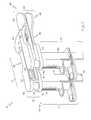
- FIGS. 1-4show various perspective views of an embodiment of a ligament balancer.
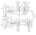
- FIGS. 5-6show perspective views of another embodiment of a ligament balancer.
- FIG. 7shows a perspective view of yet another embodiment of a ligament balancer.
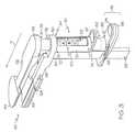
- FIG. 8shows a first sensor component interfacing with a distal femur and a proximal tibia.
- references in the specification to “one embodiment”, “an embodiment”, “an example embodiment”, etc.,indicate that the embodiment described may include a particular feature, structure, or characteristic, but every embodiment may not necessarily include the particular feature, structure, or characteristic. Moreover, such phrases are not necessarily referring to the same embodiment. Further, when a particular feature, structure, or characteristic is described in connection with an embodiment, it is submitted that it is within the knowledge of one skilled in the art to effect such feature, structure, or characteristic in connection with other embodiments whether or not explicitly described.
- the ligament balancer 10may include a sensor component 20 which is slideably coupled to a sensor component 40 via a sliding mechanism 120 ( FIG. 4 ).
- the sensor component 20may include a support 22 from which a paddle set 24 extends in a general extension direction D.
- the paddle set 24may include a tibial paddle 26 having a posterior end 28 to contact a proximal tibia 210 ( FIG. 8 ) and an anterior end 30 coupled to the support 22 .
- the paddle set 24may further include a femoral paddle 32 having a posterior end 34 to contact a distal femur 220 ( FIG.
- the tibial paddle 26may include a mounting slot or aperture 37 configured to receive additional instrumentation such as a flexion adapter, a distal femoral cutting block, and/or an anterior/posterior resection guide.
- the sensor component 40may include a support 42 from which a paddle set 44 extends in a general extension direction D.
- the paddle set 44may include a tibial paddle 46 having a posterior end 48 to contact a proximal tibia 210 ( FIG. 8 ) and an anterior end 50 coupled to the support 42 .
- the paddle set 44may further include a femoral paddle 52 having a posterior end 54 to contact a distal femur 220 ( FIG. 8 ) and an anterior end 56 coupled to the support 42 .
- the tibial paddle 46may include a mounting slot or aperture 57 configured to receive additional instrumentation such as a flexion adapter, a distal femoral cutting block, and/or an anterior/posterior resection guide.
- the support 22generally defines a sensor to sense a displacement between paddles 26 , 32 of the paddle set 24 and a tensor to sense and/or provide a force between paddles 26 , 32 of the paddle set 24 .
- the support 42generally defines a sensor to sense a displacement between paddles 46 , 52 of the paddle set 44 and a tensor to sense and/or provide a force between paddles 46 , 52 of the paddle set 44 .
- the support 22permits movement of the femoral paddle 32 with respect to the tibial paddle 26 to determine a displacement 230 between a portion 212 of the proximal tibia 210 and a condyle 222 of the distal femur 220 . See, FIG. 8 .
- the support 42permits movement of the femoral paddle 52 with respect to the tibial paddle 46 to determine a displacement 232 between a portion 214 of the proximal tibia 210 and a condyle 224 of the distal femur 220 . Referring to FIGS.
- the paddle set 24 and paddle set 44may have patellar tendon cutouts 25 , 45 to permit entry of the paddle set 24 and the paddle set 44 into the knee without averting the patella and the patellar tendon 240 as the cutouts 25 , 45 provide clearance between the paddle sets 24 , 44 and the patellar tendon 240 .
- each support 22 , 42includes a housing 70 having an upper end 72 and a lower end 74 , a displacement cylinder 76 having an upper end 78 and a lower end 80 , and a tensor cylinder 82 having an upper end 84 and a lower end 86 .
- an anterior end 30 , 50 of each tibial paddle 26 , 46may be coupled to a respective housing 70 such that each tibial paddle 26 , 46 generally extends away from the housings 70 in the extension direction D.
- an anterior end 36 , 56 of each femoral paddle 32 , 52may be coupled to a respective displacement cylinder 76 such that each femoral paddle 32 , 52 generally extends away from the displacement cylinder 76 in the extension direction D.
- the housing 70 , displacement cylinder 76 and tensor cylinder 82 of each support 22 , 42may be telescopically coupled to one another.
- the housing 70 and each cylinder 76 , 82in one embodiment comprises a circular cross section and a slightly different internal and external diameter.
- the housing 70 and cylinders 76 , 82may comprise other shapes such as, for example, square, oval, triangular or other cross sections.
- Each tensor cylinder 82may be telescopically coupled with a corresponding housing 70 .
- the upper end 84 of the tensor cylinder 82may be inserted into the lower end 74 of the housing 70 permitting movement of the lower end 86 of the tensor cylinder 82 in relation to the lower end 74 of the housing 70 as the tensor cylinder 82 is extended from or retracted into the housing 70 .
- Each displacement cylinder 76may be telescopically coupled with a corresponding tensor cylinder 82 and housing 70 .
- the lower end 80 of a displacement cylinder 76may be inserted into the upper end 84 of a tensor cylinder 82 permitting movement of the upper end 78 of the displacement cylinder 76 in relation to the lower end 86 of the tensor cylinder 82 as the displacement cylinder 76 extends from or retracts into the tensor cylinder 82 .
- telescopically coupling the displacement cylinder 76 with the tensor cylinder 82also telescopically couples the displacement cylinder 76 with the housing 70 due to the displacement cylinder 76 being telescopically coupled with the tensor cylinder 82 .
- Each support 22 , 42further includes a rail 90 coupled to the housing 70 such that a distal end of the rail 90 extends beyond the lower end 74 of the housing 70 .
- a locking mechanism 92couples the tensor cylinder 82 to the rail 90 .
- the locking mechanism 92when locked, prevents the tensor cylinder 82 from moving in relation to the housing 70 .
- the locking mechanism 92slides along the rail 90 thus permitting the tensor cylinder 82 to be moved in relation to the housing 70 .
- the tensor cylinder 82when unlocked, the tensor cylinder 82 may be extended from the housing 70 thus resulting in the lower end 86 of the tensor cylinder 82 being extended away from the lower end 74 of the housing 70 , or the tensor cylinder 82 may be retracted into the housing 70 thus resulting in the lower end 86 of the tensor cylinder 82 being retracted toward the lower end 74 of the housing 70 .
- a pin or stop 93 on the rail 90may prevent over extending the tensor cylinder 82 and/or accidentally sliding the locking mechanism 92 off the rail 90 .
- the tensor cylinder 82includes a lever 94 coupled toward the lower end 86 to aid in extending or retracting the tensor cylinder 82 .
- the locking mechanism 92includes a release lever 96 aligned with the lever 94 of the tensor cylinder 82 .
- the usermay squeeze the lever 94 and release lever 96 together in order to unlock the tensor cylinder 82 and adjust the position of the tensor cylinder 82 .
- a leaf spring 98 of the locking mechanism 92may return the locking mechanism 92 to a locked state in response to the user releasing the lever 94 and release lever 96 , thus locking the tensor cylinder 82 into place.
- the housing 70includes a lever 97 coupled toward the lower end 74 to aid in adjusting displacement between paddles of the corresponding paddle set 24 , 44 .
- a lever 97coupled toward the lower end 74 to aid in adjusting displacement between paddles of the corresponding paddle set 24 , 44 .
- raising the lever 97 with respect to a locked lever 94generally results in reducing the displacement between paddles of the corresponding paddle set 24 , 44 .
- lowering the lever 97 with respect to the locked lever 94generally results in increasing the displacement between paddles of the corresponding paddle set 24 , 44 .
- the tensor cylinder 82 ′includes a handle 94 ′ coupled toward the lower end 86 ′ of the tensor cylinder 82 ′ to aid in extending or retracting the tensor cylinder 82 ′.
- the locking mechanism 92 ′includes a release lever 96 ′ aligned with the handle 94 ′ but shorter in length than the handle 94 ′ to permit use of the handle 94 ′ without releasing the locking mechanism 92 ′.
- the locking mechanism 92 ′further includes an extension spring 98 ′ coupled to the rail 90 ′ and the release lever 96 ′ to return the locking mechanism 92 ′ to a locked state in response to the user releasing the release lever 96 ′.
- the housing 70 ′includes a lever 97 ′ coupled toward the lower end 74 ′ to aid in adjusting displacement between paddles of the corresponding paddle set 24 ′, 44 ′. It should be appreciated that raising the lever 97 ′ with respect to a locked lever 94 ′ generally results in reducing the displacement between paddles of the corresponding paddle set 24 ′, 44 ′. Conversely, lowering the lever 97 ′ with respect to the locked lever 94 ′ generally results in increasing the displacement between paddles of the corresponding paddle set 24 ′, 44 ′.
- each support 22 , 42may include a compression spring 100 positioned within and coaxial to the housing 70 , displacement cylinder 76 , and tensor cylinder 82 .
- the spring 100may be positioned between the lower end 86 of the tensor cylinder 82 and the upper end 78 of the displacement cylinder 76 .
- the spring 100may assert a force between the lower end 86 of the tensor cylinder 82 and the upper end 78 of displacement cylinder 76 .
- a user of the ligament balancer 10may selectably adjust the load upon the compression spring 100 by releasing the locking mechanism 92 and extending or retracting the tensor cylinder 82 via levers 94 , 96 .
- the load upon the compression spring 100results in the compression spring 100 applying a force to the displacement cylinder 76 which translates the selectable force to the femoral paddle 32 , 52 of the corresponding paddle set 24 , 44 .
- the housing 70 and tensor cylinder 82respectively include openings 102 , 104 .
- the housing opening 102 and tensor opening 104are aligned such that an indicator 106 upon the displacement cylinder 76 may be viewed through the openings 102 , 104 . Since the tibial paddles 26 , 46 , in one embodiment, are stationary with respect to the corresponding housings 70 , movement of the indicator 106 in relation to the housing 70 corresponds to movement of the corresponding femoral paddle 32 , 52 to its corresponding tibial paddle 26 , 46 .
- the housing 70in one embodiment, includes a displacement scale 108 which relates the position of the indicator 106 relative to the housing 70 to the displacement of the corresponding femoral paddle 32 , 52 from its corresponding tibial paddle 26 , 46 .
- the tensor cylinder 82includes force ranges 110 which relate the position of the indicator 106 relative to the tensor cylinder 82 to the force applied between the corresponding paddle set 24 , 44 .
- the tensor cylinder 82includes three force ranges labeled A, B and C in the figures. However, other embodiments may include a different number of force ranges or may include a force scale providing a measurement of the force applied to the corresponding paddle set 24 , 44 instead of or in addition to an indication of a general range.
- the sensor component 20is slideably coupled to the sensor component 40 via a sliding mechanism 120 ( FIG. 4 ).
- the sliding mechanism 120generally permits extending the posterior ends of one paddle set 24 , 44 in the extension direction D so that posterior ends of the extended paddle set 24 , 44 extend beyond in posterior ends of the other paddle set 24 , 44 .
- the sliding mechanism 120in one embodiment may include a track 122 and a runner 124 .
- the track 122may be coupled to or otherwise incorporated into the tibial paddle 26 .
- the track 122may also run generally along the length of the tibial paddle 26 in the extension direction D between its anterior end 30 and the posterior end 28 .
- the runner 124may be coupled to or otherwise incorporated into the tibial paddle 46 near a midpoint between its posterior end 48 and anterior end 50 .
- the track 122is coupled to the tibial paddle 46 and the runner 124 is coupled to the tibial paddle 26 .
- the runner 124may be slideably coupled to the track 122 thereby slideably coupling the sensor component 40 to the sensor component 20 .
- the runner 124may be restricted to movement along the track 122 in the extension direction D. Accordingly, moving the sensor component 20 in the extension direction D with respect to the sensor component 40 results in the runner 124 of the sliding mechanism 120 following the track 122 in the extension direction D.
- the sliding mechanism 120 ′ of FIGS. 5-6may include a track and a runner similar to the track 122 ( FIG. 2 ) and runner 124 ( FIG. 3 ) of the balancer 10 .
- the trackmay be coupled to or otherwise incorporated into the tibial paddle 26 ′.
- the trackmay also extend beyond an anterior end 30 ′ of the tibial paddle 26 ′ and may run generally between its extended anterior end 126 ′ and a point between the posterior end 28 ′ and the anterior end 30 ′ of the tibial paddle 26 ′.
- the runnermay be coupled to or otherwise incorporated into the tibial paddle 46 ′ near a point near its anterior end 50 ′.
- the trackis coupled to the tibial paddle 46 ′ and the runner is coupled to the tibial paddle 26 ′.
- the runnermay be slideably coupled to the track thereby slideably coupling the sensor component 40 ′ to the sensor component 20 ′.
- the runnermay be restricted to movement along the track in the extension direction D. Accordingly, moving the sensor component 20 ′ in the extension direction D with respect to the sensor component 40 ′ results in the runner of the sliding mechanism 120 ′ following the track in the extension direction D.
- ligament balancers 10 , 10 ′movement of the femoral paddles may generally be performed manually as a result of actuating the locking mechanisms 92 , 92 ′ and levers and/or handles of the ligament balancers 10 , 10 ′.
- the ligament balancer 10 ′′ shown in FIG. 7replaces the manual controls of the ligament balancers 10 , 10 ′ with automated mechanisms.
- the ligament balancer 10 ′′may include a force sensor 330 , a displacement sensor 332 , and an actuator 334 positioned within a housing 70 ′′ of each sensor component 20 ′′, 40 ′′.
- Each force sensor 330may be operatively coupled to the displacement cylinder 76 ′′ of its respective sensor component 20 ′′, 40 ′′ and may generate an output signal, such as a voltage signal, indicative of a magnitude of force applied to its respective femoral paddle 32 ′′, 52 ′′.
- each force sensor 330may comprise a load cell such as miniature load cell.
- Each displacement sensor 332 of its respective sensor component 20 ′′, 40 ′′may generate an output signal indicative of respective displacement 230 , 232 ( FIG. 8 ) between its respective paddle set 24 ′′, 44 ′′.
- each displacement sensor 332may comprise an electrical device to generate electrical output signals indicative of the respective displacements 230 , 232 .
- Each actuator 334may be operatively coupled to a respective displacement cylinder 76 ′′ and may extend or retract the respective displacement cylinder 76 ′′ in response to a corresponding control signal.
- each actuator 334may comprise a stepper motor.
- each actuator 334may comprise a linear actuator.
- each actuator 334may also be embodied as any prime mover devices operable to extend or retract the respective displacement cylinders 76 ′′.
- Each support 22 ′′, 42 ′′ of the ligament balancer 10 ′′ illustrated in FIG. 7may also include a user interface 336 , a controller 338 , and a power supply 340 positioned on or in the respective housing 70 ′′.
- the user interface 336may include a display screen 342 and a number of user buttons 344 .
- the display screens 342may be replaced with a series of light-emitting-diodes (LEDs) or a collection of visual indicators to provide simplified visual feedback to the user of the ligament balancer 10 ′′.
- the user interfaces 336may be replaced by a remote user interface(s) such as a user interface module that is separate from the supports 22 ′′, 42 ′′. In such an embodiment, the remote user interface(s) may communicate with the controllers 338 via wired or wireless communication.
- Each controller 338may comprise any type of controller including, for example, general purpose micro-controllers, microprocessors, or application specific integrated circuits (ASICs).
- Each power supply 340may comprise any device capable of supplying power to the other respective components such as controllers 338 .
- the power supplies 340may comprise replaceable batteries.
- the power supplies 340may comprise rechargeable battery packs.
- the ligament balancer 10 ′′may include appropriate charging contacts to allow the recharging of the battery packs.
- the ligament balancer 10 ′′includes two user interfaces, two controllers, and two power supplies, it should be appreciated that in other embodiments the ligament balancer 10 ′′ may include only one user interface, one controller, and/or one power supply.
- the ligament balancer 10 ′′may include a single controller positioned in one of the supports 22 ′′, 42 ′′ and communicatively coupled to each of the force sensors 330 , the displacement sensors 332 , and the actuators 334 .
- the ligament balancer 10 ′′may include a single user interface that is communicatively coupled to each of the controllers 338 (or to a single controller).
- the ligament balancers 10 , 10 ′, 10 ′′may be inserted into a patient's knee via an medial, lateral or anterior approach.
- the ligament balancer 10is shown with the sensor component 20 positioned such that the paddle set 24 extends beyond the paddle set 44 in the direction of extension D.
- the surgeonmay slide the sensor component 20 with respect to the sensor component 40 such that the paddle set 24 extends beyond the paddle set 44 in the direction of extension D, thus configuring the sensor component 20 for a far side of the knee 200 that is away from the approach and the sensor component 20 for a near side of the knee 200 which is proximate the approach.
- FIG. 1shows a converse configuration wherein the paddle set 44 extend beyond the paddle set 24 in the direction of extension D.
- the sensor component 40is not shown in FIG. 8 in order to not obscure the interaction between the sensor component 20 and the knee 200 .
- extending the paddle set 24 beyond the paddle set 44positions the posterior end 28 of the tibial paddle 26 to contact a portion 212 of the proximal tibia 210 which is away from the approach of the ligament balancer 10 into the knee 200 .
- the posterior end 34is positioned to contact a condyle 222 of the distal femur 220 which is away from the approach.
- extending the paddle set 24 beyond the paddle set 44positions the posterior end 48 of the tibial paddle 46 to contact a portion 214 of the proximal tibia 210 which is near the approach or entry of the ligament balancer 10 into the knee 200 .
- the posterior end 54is positioned to contact a condyle 224 of the distal femur 220 which is near the approach.
- the depicted approachwould be a medial approach.
- the portion 212 of the proximal tibia 210corresponds to a lateral portion of the proximal tibia
- the portion 214 of the proximal tibia 210corresponds to a medial portion of the proximal tibia 210
- the condyle 222corresponds to a lateral condyle of the distal femur 220
- the condyle 224corresponds to a medial condyle of the distal femur 220 .
- the sensor component 20may be referred to as a lateral sensor component having a lateral paddle set to measure a lateral displacement and force between lateral portions of the proximal tibia 210 and distal femur 220 .
- the sensor component 40may be referred to as a medial sensor component having a medial paddle set to measure a medial displacement and force between medial portions of the proximal tibia 210 and the distal femur 220 .
- the portion 212 of the proximal tibia 210corresponds to a medial portion of the proximal tibia 210
- the portion 214 of the proximal tibia 210corresponds to a lateral portion of the proximal tibia 210
- the condyle 222corresponds to a medial condyle of the distal femur 220
- the condyle 224corresponds to a lateral condyle of the distal femur 220 .
- the sensor component 20may be referred to as a medial sensor component having a medial paddle set to measure a medial displacement and force between medial portions of the proximal tibia 210 and distal femur 220 .
- the sensor component 40may be referred to as a lateral sensor component having a lateral paddle set to measure a lateral displacement and force between lateral portions of the proximal tibia 210 and the distal femur 220 .
Landscapes
- Health & Medical Sciences (AREA)
- Life Sciences & Earth Sciences (AREA)
- Surgery (AREA)
- Engineering & Computer Science (AREA)
- Public Health (AREA)
- Orthopedic Medicine & Surgery (AREA)
- Veterinary Medicine (AREA)
- Transplantation (AREA)
- Nuclear Medicine, Radiotherapy & Molecular Imaging (AREA)
- General Health & Medical Sciences (AREA)
- Animal Behavior & Ethology (AREA)
- Biomedical Technology (AREA)
- Heart & Thoracic Surgery (AREA)
- Vascular Medicine (AREA)
- Biophysics (AREA)
- Oral & Maxillofacial Surgery (AREA)
- Cardiology (AREA)
- Physical Education & Sports Medicine (AREA)
- Medical Informatics (AREA)
- Molecular Biology (AREA)
- Prostheses (AREA)
- Surgical Instruments (AREA)
Abstract
Description
Claims (18)
Priority Applications (9)
| Application Number | Priority Date | Filing Date | Title |
|---|---|---|---|
| US12/147,708US8197489B2 (en) | 2008-06-27 | 2008-06-27 | Knee ligament balancer |
| ES09163230TES2398614T3 (en) | 2008-06-27 | 2009-06-19 | Ligament balancer |
| DK09163230.7TDK2138107T3 (en) | 2008-06-27 | 2009-06-19 | Ligament Balancing Instrument |
| EP09163230AEP2138107B1 (en) | 2008-06-27 | 2009-06-19 | Ligament balancer |
| ZA2009/04494AZA200904494B (en) | 2008-06-27 | 2009-06-26 | Knee ligament balancer |
| AU2009202601AAU2009202601B2 (en) | 2008-06-27 | 2009-06-26 | Knee ligament balancer |
| JP2009151790AJP5335575B2 (en) | 2008-06-27 | 2009-06-26 | Knee ligament balancer |
| CN200910158656.5ACN101612055B (en) | 2008-06-27 | 2009-06-29 | Balancer for ligaments of knee |
| US13/478,661US8562617B2 (en) | 2008-06-27 | 2012-05-23 | Knee ligament balancer |
Applications Claiming Priority (1)
| Application Number | Priority Date | Filing Date | Title |
|---|---|---|---|
| US12/147,708US8197489B2 (en) | 2008-06-27 | 2008-06-27 | Knee ligament balancer |
Related Child Applications (1)
| Application Number | Title | Priority Date | Filing Date |
|---|---|---|---|
| US13/478,661DivisionUS8562617B2 (en) | 2008-06-27 | 2012-05-23 | Knee ligament balancer |
Publications (2)
| Publication Number | Publication Date |
|---|---|
| US20090326544A1 US20090326544A1 (en) | 2009-12-31 |
| US8197489B2true US8197489B2 (en) | 2012-06-12 |
Family
ID=40984952
Family Applications (2)
| Application Number | Title | Priority Date | Filing Date |
|---|---|---|---|
| US12/147,708Active2030-11-07US8197489B2 (en) | 2008-06-27 | 2008-06-27 | Knee ligament balancer |
| US13/478,661ActiveUS8562617B2 (en) | 2008-06-27 | 2012-05-23 | Knee ligament balancer |
Family Applications After (1)
| Application Number | Title | Priority Date | Filing Date |
|---|---|---|---|
| US13/478,661ActiveUS8562617B2 (en) | 2008-06-27 | 2012-05-23 | Knee ligament balancer |
Country Status (8)
| Country | Link |
|---|---|
| US (2) | US8197489B2 (en) |
| EP (1) | EP2138107B1 (en) |
| JP (1) | JP5335575B2 (en) |
| CN (1) | CN101612055B (en) |
| AU (1) | AU2009202601B2 (en) |
| DK (1) | DK2138107T3 (en) |
| ES (1) | ES2398614T3 (en) |
| ZA (1) | ZA200904494B (en) |
Cited By (22)
| Publication number | Priority date | Publication date | Assignee | Title |
|---|---|---|---|---|
| US20130103160A1 (en)* | 2010-04-22 | 2013-04-25 | Depuy (Ireland) | Composite trial prosthesis |
| US8968412B2 (en) | 2011-06-30 | 2015-03-03 | Depuy (Ireland) | Trialing system for a knee prosthesis and method of use |
| US9427336B2 (en) | 2013-08-23 | 2016-08-30 | Stryker Corporation | Intraoperative dynamic trialing |
| US20170049527A1 (en)* | 2014-06-19 | 2017-02-23 | Kyocera Medical Corporation | Measurement instrument for joint surgery |
| US9750619B2 (en) | 2011-09-07 | 2017-09-05 | Depuy Ireland Unlimited Company | Surgical instrument |
| US9861491B2 (en) | 2014-04-30 | 2018-01-09 | Depuy Ireland Unlimited Company | Tibial trial system for a knee prosthesis |
| US10195056B2 (en) | 2015-10-19 | 2019-02-05 | Depuy Ireland Unlimited Company | Method for preparing a patient's tibia to receive an implant |
| US10537445B2 (en) | 2015-10-19 | 2020-01-21 | Depuy Ireland Unlimited Company | Surgical instruments for preparing a patient's tibia to receive an implant |
| US10772641B2 (en) | 2016-12-22 | 2020-09-15 | Orthosensor Inc. | Surgical apparatus having a frame and moving support structure and method therefore |
| WO2021170591A1 (en) | 2020-02-28 | 2021-09-02 | Depuy Ireland Unlimited Company | Soft tissue balancing in knee replacement |
| US11185425B2 (en) | 2016-12-22 | 2021-11-30 | Orthosensor Inc. | Surgical tensor configured to distribute loading through at least two pivot points |
| US20210378651A1 (en)* | 2018-04-11 | 2021-12-09 | Vivek Mohan | A haptic based system for bone gap measurement and distraction |
| US11266512B2 (en) | 2016-12-22 | 2022-03-08 | Orthosensor Inc. | Surgical apparatus to support installation of a prosthetic component and method therefore |
| US11284873B2 (en) | 2016-12-22 | 2022-03-29 | Orthosensor Inc. | Surgical tensor where each distraction mechanism is supported and aligned by at least two guide shafts |
| US11291437B2 (en) | 2016-12-22 | 2022-04-05 | Orthosensor Inc. | Tilting surgical tensor to support at least one bone cut |
| US11432811B2 (en) | 2019-05-09 | 2022-09-06 | Mako Surgical Corp. | Joint gap balancing lever and methods of use thereof |
| US11666318B2 (en) | 2019-08-30 | 2023-06-06 | Mako Surgical Corp. | Distraction device with disposable force sensor pod |
| US11678894B2 (en) | 2017-12-15 | 2023-06-20 | Jonathan P. Cabot | Knee balancing instrument |
| US11812978B2 (en) | 2019-10-15 | 2023-11-14 | Orthosensor Inc. | Knee balancing system using patient specific instruments |
| US12064358B2 (en) | 2019-09-24 | 2024-08-20 | Mako Surgical Corp. | System and method for ligament balancing using robotically held device |
| US12201534B2 (en) | 2020-01-29 | 2025-01-21 | Howmedica Osteonics Corp. | Load sensor balancer instruments |
| US12324752B2 (en) | 2012-03-31 | 2025-06-10 | Depuy Ireland Unlimited Company | Orthopaedic surgical system for determining joint forces of a patient's knee joint |
Families Citing this family (36)
| Publication number | Priority date | Publication date | Assignee | Title |
|---|---|---|---|---|
| HRP20130708T1 (en)* | 2006-10-11 | 2013-10-11 | Ignace Ghijselings | INSTALLATION DEVICE FOR FEMORAL KNEE JOINT INSTALLATION |
| US8197489B2 (en) | 2008-06-27 | 2012-06-12 | Depuy Products, Inc. | Knee ligament balancer |
| US20100250276A1 (en)* | 2009-03-26 | 2010-09-30 | Jay Pierce | System and method for an orthopedic dynamic data repository and registry for clinical |
| US8556830B2 (en)* | 2009-03-31 | 2013-10-15 | Depuy | Device and method for displaying joint force data |
| US8551023B2 (en)* | 2009-03-31 | 2013-10-08 | Depuy (Ireland) | Device and method for determining force of a knee joint |
| US8721568B2 (en) | 2009-03-31 | 2014-05-13 | Depuy (Ireland) | Method for performing an orthopaedic surgical procedure |
| US8740817B2 (en)* | 2009-03-31 | 2014-06-03 | Depuy (Ireland) | Device and method for determining forces of a patient's joint |
| US8597210B2 (en)* | 2009-03-31 | 2013-12-03 | Depuy (Ireland) | System and method for displaying joint force data |
| EP2775966B1 (en) | 2011-10-24 | 2015-09-16 | Synvasive Technology, Inc. | Knee balancing systems |
| US9381011B2 (en) | 2012-03-29 | 2016-07-05 | Depuy (Ireland) | Orthopedic surgical instrument for knee surgery |
| US10098761B2 (en) | 2012-03-31 | 2018-10-16 | DePuy Synthes Products, Inc. | System and method for validating an orthopaedic surgical plan |
| US10070973B2 (en) | 2012-03-31 | 2018-09-11 | Depuy Ireland Unlimited Company | Orthopaedic sensor module and system for determining joint forces of a patient's knee joint |
| US9545459B2 (en) | 2012-03-31 | 2017-01-17 | Depuy Ireland Unlimited Company | Container for surgical instruments and system including same |
| US20150209158A1 (en)* | 2012-07-04 | 2015-07-30 | Depuy (Ireland) | Measuring instrument for use in orthopaedic surgery |
| USD696782S1 (en) | 2013-03-08 | 2013-12-31 | Stryker Corporation | Joint stabilizing instrument |
| GB2526724B (en)* | 2013-05-23 | 2016-06-01 | Moholkar Kirti | Instrument for use in knee replacement surgery |
| NZ715261A (en) | 2013-05-23 | 2019-02-22 | Kirti Moholkar | Improvements in or relating to assemblies for use in knee replacement surgery |
| WO2015057814A1 (en)* | 2013-10-15 | 2015-04-23 | XpandOrtho, Inc. | Actuated positioning device for arthroplasty and methods of use |
| JP2018509208A (en)* | 2015-03-19 | 2018-04-05 | マントバーニ マッテオ | Surgical aids for joints |
| EP3273918B1 (en) | 2015-03-24 | 2019-12-04 | Xpandortho, Inc. | Balancing device for arthroplasty |
| US10456211B2 (en) | 2015-11-04 | 2019-10-29 | Medicrea International | Methods and apparatus for spinal reconstructive surgery and measuring spinal length and intervertebral spacing, tension and rotation |
| WO2017185108A2 (en)* | 2016-04-28 | 2017-11-02 | Medfit Beratungs-Und Beteiligunges.M.B.H | Dynamic ligament balancing system (dlb) |
| US11229489B2 (en) | 2016-06-16 | 2022-01-25 | Zimmer, Inc. | Soft tissue balancing in articular surgery |
| US10136952B2 (en) | 2016-06-16 | 2018-11-27 | Zimmer, Inc. | Soft tissue balancing in articular surgery |
| CN106236289A (en)* | 2016-07-28 | 2016-12-21 | 上海市第十人民医院 | Femoral rotation osteotomy automatic backlash static organ in a kind of total knee arthroplasty |
| CN106667589A (en)* | 2017-01-06 | 2017-05-17 | 重庆市渝北区中医院 | Knee joint distance measurement device |
| EP3592298B1 (en)* | 2017-03-07 | 2023-12-13 | DSB Co Pty Ltd | Surgical spacer device with sensor |
| CN107334476A (en)* | 2017-06-27 | 2017-11-10 | 苏州奥特科然医疗科技有限公司 | A kind of distance-measuring device |
| JP6998393B2 (en) | 2017-07-28 | 2022-02-04 | ライト メディカル テクノロジー インコーポレイテッド | Joint osteotomy system and method |
| CN110236554B (en)* | 2019-07-19 | 2020-07-28 | 张晋 | Tibia back-and-forth movement measuring device |
| US12419625B2 (en) | 2020-04-24 | 2025-09-23 | Omicron Orthopedic Technology, Llc | Devices for dynamic sizing and sagittal balancing in total knee arthroplasty |
| CN111759312A (en)* | 2020-05-07 | 2020-10-13 | 北京天智航医疗科技股份有限公司 | Measuring device for force and clearance, measuring platform and measuring method for soft tissue balance of knee joint |
| CN111643195A (en)* | 2020-05-19 | 2020-09-11 | 北京市春立正达医疗器械股份有限公司 | Knee joint tissue balancer |
| CN112451014A (en)* | 2020-12-09 | 2021-03-09 | 王飞 | Tibia osteotomy angle regulation and control and locking plate positioning system |
| CN114847887B (en)* | 2022-07-07 | 2022-12-13 | 北京壹点灵动科技有限公司 | Measuring device for knee joint soft tissue balance and control method thereof |
| WO2025006539A1 (en)* | 2023-06-30 | 2025-01-02 | Mako Surgical Corp. | Motorized orthopedic tensor and methods of using the same |
Citations (180)
| Publication number | Priority date | Publication date | Assignee | Title |
|---|---|---|---|---|
| US4501266A (en)* | 1983-03-04 | 1985-02-26 | Biomet, Inc. | Knee distraction device |
| US4795473A (en) | 1987-01-09 | 1989-01-03 | Grimes James B | Extramedullary femoral head-neck prosthesis and method of implanting same |
| US4796610A (en) | 1987-07-02 | 1989-01-10 | Donjoy, Inc. | Lateral impact knee guard and medial collateral ligament knee brace |
| US4804000A (en) | 1987-01-21 | 1989-02-14 | Steve Lamb | Dynamic sagittal knee test apparatus |
| US4808186A (en) | 1988-02-02 | 1989-02-28 | Boehringer Mannheim Corporation | Controlled stiffness femoral hip implant |
| US4822362A (en) | 1987-05-19 | 1989-04-18 | Walker Peter S | Process and apparatus for tibial plateau compenent |
| US4825857A (en) | 1982-02-18 | 1989-05-02 | Howmedica, Inc. | Prosthetic knee implantation |
| US4828562A (en) | 1988-02-04 | 1989-05-09 | Pfizer Hospital Products Group, Inc. | Anterior cruciate ligament prosthesis |
| US4834057A (en) | 1980-03-31 | 1989-05-30 | Physical Diagnostics, Inc. | Dynamic joint motion analysis technique |
| US4856993A (en) | 1985-03-29 | 1989-08-15 | Tekscan, Inc. | Pressure and contact sensor system for measuring dental occlusion |
| US4888021A (en) | 1988-02-02 | 1989-12-19 | Joint Medical Products Corporation | Knee and patellar prosthesis |
| US4892093A (en) | 1988-10-28 | 1990-01-09 | Osteonics Corp. | Femoral cutting guide |
| US4892546A (en) | 1987-05-15 | 1990-01-09 | Howmedica Gmbh | Adjustable prosthesis for a joint bone |
| US4899761A (en) | 1988-03-31 | 1990-02-13 | Brown Mark D | Apparatus and method for measuring spinal instability |
| US4907578A (en) | 1986-07-23 | 1990-03-13 | Petersen Thomas D | Method and instruments for resection of the distal femur |
| US4926847A (en) | 1988-12-27 | 1990-05-22 | Johnson & Johnson Orthopaedics, Inc. | Surgical cutting block |
| US4932974A (en) | 1989-07-06 | 1990-06-12 | Pappas Michael J | Prosthetic device with predetermined crystal orientation |
| US4935023A (en) | 1989-01-09 | 1990-06-19 | Dow Corning Wright | Femoral surface shaping guide for knee implants |
| US4936853A (en) | 1989-01-11 | 1990-06-26 | Kirschner Medical Corporation | Modular knee prosthesis |
| US4938762A (en) | 1987-12-16 | 1990-07-03 | Protek Ag | Reference system for implantation of condylar total knee prostheses |
| US4944756A (en) | 1988-02-03 | 1990-07-31 | Pfizer Hospital Products Group | Prosthetic knee joint with improved patellar component tracking |
| US4959071A (en) | 1988-02-03 | 1990-09-25 | Biomet, Inc. | Partially stabilized knee prosthesis |
| US4963153A (en) | 1987-06-30 | 1990-10-16 | Sulzer Brothers Limited | Metal tibial anchoring part for a partial knee joint prosthesis |
| US4973331A (en) | 1989-03-08 | 1990-11-27 | Autogenesis Corporation | Automatic compression-distraction-torsion method and apparatus |
| US4979949A (en) | 1988-04-26 | 1990-12-25 | The Board Of Regents Of The University Of Washington | Robot-aided system for surgery |
| US4986281A (en) | 1984-08-23 | 1991-01-22 | Starkey Laboratories, Inc. | Method for obtaining a signal for analyzing human and animal joint functions |
| US5002547A (en) | 1987-02-07 | 1991-03-26 | Pfizer Hospital Products Group, Inc. | Apparatus for knee prosthesis |
| US5018514A (en) | 1987-06-11 | 1991-05-28 | Brace Technologies, Inc. | Knee brace |
| US5020797A (en) | 1989-12-15 | 1991-06-04 | Burns Clay A | Method and apparatus for exercising the knee while correcting for tibial subluxation |
| US5032132A (en) | 1990-01-22 | 1991-07-16 | Boehringer Mannheim Corporation | Glenoid component |
| US5033291A (en) | 1989-12-11 | 1991-07-23 | Tekscan, Inc. | Flexible tactile sensor for measuring foot pressure distributions and for gaskets |
| US5037423A (en) | 1983-10-26 | 1991-08-06 | Pfizer Hospital Products Group, Inc. | Method and instrumentation for the replacement of a knee prosthesis |
| US5056530A (en) | 1988-12-15 | 1991-10-15 | University Of Cincinnati | Method of measuring axial force in mammalian fibrous tissue and device |
| US5080675A (en) | 1990-03-12 | 1992-01-14 | Howmedica | Tibial component for a replacement knee prosthesis |
| US5082003A (en) | 1990-01-05 | 1992-01-21 | Orthopedic Systems, Inc. | Apparatus for determining interskeletal distances |
| US5098436A (en) | 1991-03-07 | 1992-03-24 | Dow Corning Wright Corporation | Modular guide for shaping of femur to accommodate intercondylar stabilizing housing and patellar track of implant |
| US5122144A (en) | 1989-09-26 | 1992-06-16 | Kirschner Medical Corporation | Method and instrumentation for unicompartmental total knee arthroplasty |
| US5125408A (en) | 1988-10-24 | 1992-06-30 | The United States Of America As Represented By The Of The Department Of Health And Human Services | Pressure sensor element and method to measure contact stress |
| US5129909A (en) | 1991-03-13 | 1992-07-14 | Sutherland Charles J | Apparatus and method for making precise bone cuts in total knee replacement |
| US5197488A (en) | 1991-04-05 | 1993-03-30 | N. K. Biotechnical Engineering Co. | Knee joint load measuring instrument and joint prosthesis |
| US5207711A (en) | 1990-01-08 | 1993-05-04 | Caspari Richard B | Knee joint prosthesis |
| US5213112A (en) | 1992-01-29 | 1993-05-25 | Pfizer Hospital Products Group, Inc. | Tension meter for orthopedic surgery |
| US5228459A (en) | 1990-01-08 | 1993-07-20 | Caspari Richard B | Method of resecting bone |
| US5234433A (en) | 1989-09-26 | 1993-08-10 | Kirschner Medical Corporation | Method and instrumentation for unicompartmental total knee arthroplasty |
| US5234434A (en) | 1992-08-17 | 1993-08-10 | Marlowe Goble E | Mutliple guide sleeve drill guide |
| US5234435A (en) | 1991-03-08 | 1993-08-10 | Seagrave Jr Richard A | Surgical method and apparatus |
| US5250050A (en) | 1987-02-07 | 1993-10-05 | Pfizer Hospital Products Group, Inc. | Apparatus for knee prosthesis |
| US5257996A (en) | 1991-12-13 | 1993-11-02 | Mcguire David A | Surgical pin passer |
| US5312411A (en) | 1992-10-27 | 1994-05-17 | Smith & Nephew Richards, Inc. | Uni-compartmental femoral knee instruments and prosthesis |
| US5326363A (en) | 1992-09-14 | 1994-07-05 | Zimmer, Inc. | Provisional implant |
| US5329933A (en) | 1991-09-24 | 1994-07-19 | Henry Graf | Device for measuring the angle of movement of two vertebrae |
| US5342367A (en) | 1992-02-20 | 1994-08-30 | Wright Medical Technology, Inc. | Rotationally and angularly adjustable tibial cutting guide and method of use |
| US5358527A (en) | 1991-03-22 | 1994-10-25 | Forte Mark R | Total knee prosthesis with resurfacing and posterior stabilization capability |
| US5364401A (en) | 1992-10-08 | 1994-11-15 | Wright Medical Technology, Inc. | External alignment system for preparing a femur for an implant |
| US5364402A (en) | 1993-07-29 | 1994-11-15 | Intermedics Orthopedics, Inc. | Tibial spacer saw guide |
| US5395401A (en) | 1991-06-17 | 1995-03-07 | Bahler; Andre | Prosthetic device for a complex joint |
| US5417694A (en) | 1993-11-08 | 1995-05-23 | Smith & Nephew Richards Inc. | Distal femoral cutting guide apparatus with anterior or posterior referencing for use in knee joint replacement surgery |
| US5425775A (en) | 1992-06-23 | 1995-06-20 | N.K. Biotechnical Engineering Company | Method for measuring patellofemoral forces |
| US5431652A (en) | 1991-12-25 | 1995-07-11 | Gunze Limited | Bone-treating devices and their manufacturing method |
| US5431653A (en) | 1993-07-06 | 1995-07-11 | Callaway; George H. | Knee joint flexion-gap distraction device |
| US5443518A (en) | 1993-07-20 | 1995-08-22 | Zimmer, Inc. | Knee position indicator |
| US5456724A (en) | 1993-12-15 | 1995-10-10 | Industrial Technology Research Institute | Load sensor for bone graft |
| US5470354A (en) | 1991-11-12 | 1995-11-28 | Biomet Inc. | Force sensing apparatus and method for orthopaedic joint reconstruction |
| US5489311A (en) | 1994-01-21 | 1996-02-06 | Joint Medical Products Corporation | Prosthesis with orientable bearing surface |
| US5496352A (en) | 1994-04-04 | 1996-03-05 | Pacesetter, Inc. | Activity sensors for implantable medical devices |
| US5514183A (en) | 1994-12-20 | 1996-05-07 | Epstein; Norman | Reduced friction prosthetic knee joint utilizing replaceable roller bearings |
| US5514144A (en) | 1993-12-20 | 1996-05-07 | Bolton; Carl W. | Drill guide device for the arthroscopic anatomic placement of a straight tibio-femoral bone tunnel for ACL reconstruction |
| US5520695A (en) | 1992-02-14 | 1996-05-28 | Johnson & Johnson Professional, Inc. | Instruments for use in knee replacement surgery |
| WO1996017552A1 (en) | 1994-12-05 | 1996-06-13 | Intermedics Orthopedics, Inc. | Knee distractor device |
| US5540696A (en) | 1995-01-06 | 1996-07-30 | Zimmer, Inc. | Instrumentation for use in orthopaedic surgery |
| US5562674A (en) | 1995-02-27 | 1996-10-08 | Zimmer, Inc. | Intramedullary rod with guide member locator |
| US5597379A (en) | 1994-09-02 | 1997-01-28 | Hudson Surgical Design, Inc. | Method and apparatus for femoral resection alignment |
| US5611774A (en) | 1992-10-23 | 1997-03-18 | Françoise Ghislaine Dumont | Knee support or replacement apparatus |
| US5613971A (en) | 1995-08-11 | 1997-03-25 | Depuy Inc. | Ratcheting tibial and femoral guide |
| US5643272A (en) | 1994-09-02 | 1997-07-01 | Hudson Surgical Design, Inc. | Method and apparatus for tibial resection |
| US5649929A (en) | 1995-07-10 | 1997-07-22 | Callaway; George Hadley | Knee joint flexion-gap distraction device |
| US5656785A (en) | 1995-08-07 | 1997-08-12 | The Charles Stark Draper Laboratory, Inc. | Micromechanical contact load force sensor for sensing magnitude and distribution of loads and tool employing micromechanical contact load force sensor |
| US5658293A (en) | 1995-10-10 | 1997-08-19 | Zimmer, Inc. | Guide platform associated with intramedullary rod |
| US5669914A (en) | 1996-02-16 | 1997-09-23 | Board Of Regents Of The University Of Colorado | Rotation alignment instrument |
| US5671695A (en) | 1994-07-28 | 1997-09-30 | Depuy Inc. | Replacement ligament graft passer and method |
| US5682886A (en) | 1995-12-26 | 1997-11-04 | Musculographics Inc | Computer-assisted surgical system |
| US5683397A (en) | 1995-02-15 | 1997-11-04 | Smith & Nephew, Inc. | Distal femoral cutting guide apparatus for use in knee joint replacement surgery |
| US5688282A (en) | 1995-08-24 | 1997-11-18 | Benois & Girard & Cie | Distraction apparatus for a knee |
| US5702463A (en) | 1996-02-20 | 1997-12-30 | Smith & Nephew Inc. | Tibial prosthesis with polymeric liner and liner insertion/removal instrument |
| US5702422A (en) | 1995-12-06 | 1997-12-30 | Stone; Kevin R. | Anterior cruciate ligament repair method |
| US5733292A (en) | 1995-09-15 | 1998-03-31 | Midwest Orthopaedic Research Foundation | Arthroplasty trial prosthesis alignment devices and associated methods |
| US5735904A (en) | 1995-07-05 | 1998-04-07 | Pappas; Michael J. | Spacer for establishng prosthetic gap and ligamentous tension |
| US5743909A (en) | 1996-06-24 | 1998-04-28 | Collette; Michel | Radiological method for preoperative determination of isometric attachment points of an ACL graft, surgical aiming instrument and method of use |
| US5769894A (en) | 1997-02-05 | 1998-06-23 | Smith & Nephew, Inc. | Graft attachment device and method of attachment |
| US5782925A (en) | 1997-11-06 | 1998-07-21 | Howmedica Inc. | Knee implant rotational alignment apparatus |
| US5800438A (en) | 1995-10-23 | 1998-09-01 | Finsbury (Instruments) Limited | Surgical tool |
| US5810827A (en) | 1994-09-02 | 1998-09-22 | Hudson Surgical Design, Inc. | Method and apparatus for bony material removal |
| US5824104A (en) | 1996-04-17 | 1998-10-20 | Finsbury (Instruments) Limited | Meniscal knee prosthesis having bollard and mooring attachment means |
| US5840047A (en) | 1996-04-16 | 1998-11-24 | Prosthetic Sensing Technologies, Llc | Sensor device for monitoring a prosthetic device |
| US5860980A (en) | 1997-09-15 | 1999-01-19 | Axelson, Jr.; Stuart L. | Surgical apparatus for use in total knee arthroplasty and surgical methods for using said apparatus |
| US5879389A (en) | 1995-04-07 | 1999-03-09 | Koshino; Tomihisa | Medical substituting element for hard tissues and artificial joint |
| US5880976A (en) | 1997-02-21 | 1999-03-09 | Carnegie Mellon University | Apparatus and method for facilitating the implantation of artificial components in joints |
| US5891150A (en) | 1996-12-04 | 1999-04-06 | Chan; Kwan-Ho | Apparatus and method for fixing a ligament in a bone tunnel |
| US5911723A (en) | 1996-05-28 | 1999-06-15 | Howmedice International Inc. | Surgical apparatus |
| US5935086A (en) | 1994-11-01 | 1999-08-10 | Beacon; Jonathan Paul | Orthopaedic measurement and display system |
| US6013103A (en) | 1996-07-11 | 2000-01-11 | Wright Medical Technology, Inc. | Medial pivot knee prosthesis |
| US6019767A (en) | 1990-07-16 | 2000-02-01 | Arthrotek | Tibial guide |
| US6022377A (en) | 1998-01-20 | 2000-02-08 | Sulzer Orthopedics Inc. | Instrument for evaluating balance of knee joint |
| US6034296A (en) | 1997-03-11 | 2000-03-07 | Elvin; Niell | Implantable bone strain telemetry sensing system and method |
| US6056756A (en) | 1998-08-11 | 2000-05-02 | Johnson & Johnson Professional, Inc. | Femoral tensing and sizing device |
| US6056752A (en) | 1997-10-24 | 2000-05-02 | Smith & Nephew, Inc. | Fixation of cruciate ligament grafts |
| US6080154A (en) | 1997-03-22 | 2000-06-27 | Atlantech Medical Devices Limited | Locating anchor |
| US6086592A (en) | 1998-01-07 | 2000-07-11 | Smith & Nephew, Inc. | Tissue graft impingement device |
| US6096043A (en) | 1998-12-18 | 2000-08-01 | Depuy Orthopaedics, Inc. | Epicondylar axis alignment-femoral positioning drill guide |
| US6113604A (en) | 1997-01-14 | 2000-09-05 | Ethicon, Inc. | Method and apparatus for fixing a graft in a bone tunnel |
| US6126692A (en) | 1998-06-25 | 2000-10-03 | New York Society For The Relief Of The Ruptured And Crippled Maintaining The Hospital For Special Surgery | Retaining mechanism for a modular tibial component of a knee prosthesis |
| US6174294B1 (en) | 1996-08-02 | 2001-01-16 | Orbital Technologies, Inc. | Limb load monitor |
| US20010021877A1 (en) | 2000-02-24 | 2001-09-13 | Aesculap | Femoral component of a knee prosthetic including three curvature radii |
| US20020029045A1 (en) | 2000-01-14 | 2002-03-07 | Bonutti Peter M. | Method of performing surgery |
| US20020052606A1 (en) | 2000-01-14 | 2002-05-02 | Bonutti Peter M. | Method of performing surgery |
| US6447448B1 (en) | 1998-12-31 | 2002-09-10 | Ball Semiconductor, Inc. | Miniature implanted orthopedic sensors |
| US20020133175A1 (en) | 2001-02-27 | 2002-09-19 | Carson Christopher P. | Surgical navigation systems and processes for unicompartmental knee arthroplasty |
| US20020156480A1 (en)* | 2001-03-29 | 2002-10-24 | Sulzer Orthopedics Ltd. | Spreader apparatus for knee joints |
| US6488711B1 (en) | 1997-12-19 | 2002-12-03 | Josef Grafinger | Knee-joint prosthesis |
| US20030028196A1 (en) | 2000-01-14 | 2003-02-06 | Bonutti Peter M. | Method of performing surgery |
| US20030069591A1 (en) | 2001-02-27 | 2003-04-10 | Carson Christopher Patrick | Computer assisted knee arthroplasty instrumentation, systems, and processes |
| US20030069644A1 (en) | 2001-10-05 | 2003-04-10 | Nebojsa Kovacevic | Dual-tray teletibial implant |
| US6553681B2 (en) | 2000-02-29 | 2003-04-29 | Carl Roger Ekholm, Jr. | Methods for measuring a bio-material for use in an implant |
| US6575980B1 (en) | 1997-01-28 | 2003-06-10 | New York Society For The Ruptured And Crippled Maintaining The Hospital For Special Surgery | Method and apparatus for femoral resection |
| US6589283B1 (en) | 2001-05-15 | 2003-07-08 | Biomet, Inc. | Elongated femoral component |
| US20030130665A1 (en) | 2000-03-10 | 2003-07-10 | Pinczewski Leo Arieh | Method of arthroplastly on a knee joint and apparatus for use in same |
| US20030144669A1 (en) | 2001-12-05 | 2003-07-31 | Robinson Randolph C. | Limb lengthener |
| WO2003065949A2 (en) | 2002-02-08 | 2003-08-14 | Whiteside Leo A | Apparatus for fitting implants and balancing ligaments |
| US6610096B2 (en) | 2001-08-22 | 2003-08-26 | Macdonald Stuart G. | Prosthetic implants having enhanced utility |
| EP1348382A2 (en) | 2002-03-29 | 2003-10-01 | DePuy Orthopaedics, Inc. | Instruments for flexion gap adjustment of a knee prosthesis |
| US6632225B2 (en) | 2001-06-20 | 2003-10-14 | Zimmer, Inc. | Method and apparatus for resecting a distal femur and a proximal tibia in preparation for implanting a partial knee prosthesis |
| US20030236472A1 (en) | 2002-06-19 | 2003-12-25 | James Van Hoeck | Systems and methods for moving anatomical elements |
| WO2004008988A2 (en) | 2002-07-23 | 2004-01-29 | Ortho Development Corporation | Knee balancing block |
| US20040019382A1 (en) | 2002-03-19 | 2004-01-29 | Farid Amirouche | System and method for prosthetic fitting and balancing in joints |
| US6706005B2 (en) | 2000-08-25 | 2004-03-16 | The Cleveland Clinic Foundation | Apparatus and method for assessing loads on adjacent bones |
| US20040064191A1 (en) | 2002-09-30 | 2004-04-01 | Wasielewski Ray C. | Apparatus, system and method for intraoperative performance analysis during joint arthroplasty |
| US20040064073A1 (en) | 2002-09-30 | 2004-04-01 | Heldreth Mark A. | Modified system and method for intraoperative tension assessment during joint arthroplasty |
| US20040097951A1 (en) | 2002-11-18 | 2004-05-20 | Steffensmeier Scott J. | Measurement instrument for use in orthopaedic surgery |
| US20040122441A1 (en) | 2002-12-09 | 2004-06-24 | Zimmer Kabushiki Kaisha | Measuring apparatus for total knee replacement operation |
| US6821299B2 (en) | 2002-07-24 | 2004-11-23 | Zimmer Technology, Inc. | Implantable prosthesis for measuring six force components |
| US20040243148A1 (en) | 2003-04-08 | 2004-12-02 | Wasielewski Ray C. | Use of micro- and miniature position sensing devices for use in TKA and THA |
| US20050021044A1 (en) | 2003-06-09 | 2005-01-27 | Vitruvian Orthopaedics, Llc | Surgical orientation device and method |
| US20050038442A1 (en) | 2003-08-15 | 2005-02-17 | Finsbury (Development) Limited | Apparatus, operating means and process |
| DE10335410A1 (en) | 2003-08-01 | 2005-02-24 | Aesculap Ag & Co. Kg | Device for stretching knee area for evaluation of tension of ligaments, comprising specifically shaped lifting elements |
| WO2005023120A1 (en) | 2003-09-04 | 2005-03-17 | Mathys Ag Bettlach | Hydraulic ligament-tensioning device |
| US20050113846A1 (en) | 2001-02-27 | 2005-05-26 | Carson Christopher P. | Surgical navigation systems and processes for unicompartmental knee arthroplasty |
| US6905513B1 (en) | 2002-08-30 | 2005-06-14 | Biomet, Inc. | Knee prosthesis with graft ligaments |
| US20050149041A1 (en) | 2003-11-14 | 2005-07-07 | Mcginley Brian J. | Adjustable surgical cutting systems |
| US20050177170A1 (en) | 2004-02-06 | 2005-08-11 | Synvasive Technology, Inc. | Dynamic knee balancer with pressure sensing |
| US20050234465A1 (en) | 2004-03-31 | 2005-10-20 | Mccombs Daniel L | Guided saw with pins |
| US20050234466A1 (en) | 2004-03-31 | 2005-10-20 | Jody Stallings | TLS adjustable block |
| US20050234448A1 (en) | 2004-03-19 | 2005-10-20 | Mccarthy James | Implantable bone-lengthening device |
| US20050234332A1 (en) | 2004-01-16 | 2005-10-20 | Murphy Stephen B | Method of computer-assisted ligament balancing and component placement in total knee arthroplasty |
| US20050251026A1 (en) | 2003-06-09 | 2005-11-10 | Vitruvian Orthopaedics, Llc | Surgical orientation system and method |
| US6972039B2 (en) | 1999-03-01 | 2005-12-06 | Biomet, Inc. | Floating bearing knee joint prosthesis with a fixed tibial post |
| US6984249B2 (en) | 2001-04-25 | 2006-01-10 | Walde Mar Link Gmbh & Co. Kg | Knee prosthesis with a flexion hinge |
| US20060081063A1 (en)* | 2004-10-11 | 2006-04-20 | Timo Neubauer | Ligament force detection system |
| US20060149277A1 (en) | 2003-02-27 | 2006-07-06 | Philippe Cinquin | Knee distractor |
| US20060161051A1 (en) | 2005-01-18 | 2006-07-20 | Lauralan Terrill-Grisoni | Method of computer-assisted ligament balancing and component placement in total knee arthroplasty |
| US20060224088A1 (en) | 2005-03-29 | 2006-10-05 | Roche Martin W | Body parameter detecting sensor and method for detecting body parameters |
| US20060241569A1 (en) | 2005-03-31 | 2006-10-26 | Disilvestro Mark R | Method and apparatus for use in balancing ligaments of a knee |
| US20060271056A1 (en) | 2005-05-10 | 2006-11-30 | Smith & Nephew, Inc. | System and method for modular navigated osteotome |
| US7153281B2 (en) | 2002-10-30 | 2006-12-26 | Mekanika, Inc | Apparatus and method for measuring instability of a motion segment unit of a spine |
| WO2007036694A1 (en) | 2005-09-30 | 2007-04-05 | Depuy International Limited | Instrument assembly for use in knee joint replacement surgery |
| WO2007036699A1 (en) | 2005-09-30 | 2007-04-05 | Depuy International Limited | A distractor instrument |
| US20070162142A1 (en) | 2005-06-15 | 2007-07-12 | Vitruvian Orthopaedics, Llc | Knee surgery method and apparatus |
| US20070219561A1 (en) | 2006-03-20 | 2007-09-20 | Perception Raisonnement Action En Medecine | Distractor system |
| US20070233144A1 (en)* | 2006-03-20 | 2007-10-04 | Stephane Lavallee | Distractor system |
| US20070239165A1 (en) | 2006-03-29 | 2007-10-11 | Farid Amirouche | Device and method of spacer and trial design during joint arthroplasty |
| US20070244488A1 (en)* | 2006-03-03 | 2007-10-18 | Robert Metzger | Tensor for use in surgical navigation |
| US7412897B2 (en) | 2004-06-15 | 2008-08-19 | Synthes (U.S.A.) | Device for measuring tibio-femoral force amplitudes and force locations in total knee arthroplasty |
| EP1645229B1 (en) | 2004-10-11 | 2008-11-26 | BrainLAB AG | System for determining the ligament force |
| US20090005708A1 (en) | 2007-06-29 | 2009-01-01 | Johanson Norman A | Orthopaedic Implant Load Sensor And Method Of Interpreting The Same |
| US20090018544A1 (en) | 2007-07-13 | 2009-01-15 | Zimmer, Inc. | Method and apparatus for soft tissue balancing |
| US20090099570A1 (en) | 2007-10-10 | 2009-04-16 | Francois Paradis | Hip replacement in computer-assisted surgery |
| US20090326544A1 (en) | 2008-06-27 | 2009-12-31 | Ryan Chessar | Knee ligament balancer |
| WO2010011978A1 (en) | 2008-07-24 | 2010-01-28 | OrthAlign, Inc. | Systems and methods for joint replacement |
| WO2010022272A1 (en) | 2008-08-20 | 2010-02-25 | Synvasive Technology, Inc. | Sensing force during partial and total knee replacement surgery |
| WO2010030809A1 (en) | 2008-09-10 | 2010-03-18 | Orthalign, Inc | Hip surgery systems and methods |
| EP1915951B1 (en) | 2006-10-26 | 2011-06-29 | Howmedica Osteonics Corp. | Knee distractor |
Family Cites Families (8)
| Publication number | Priority date | Publication date | Assignee | Title |
|---|---|---|---|---|
| US7309363B2 (en)* | 2004-11-24 | 2007-12-18 | Depuy Products, Inc. | Adjustable knee tibial trial insert |
| CN105030296A (en)* | 2006-02-06 | 2015-11-11 | 康复米斯公司 | Patient selectable joint arthroplasty devices and surgical tools |
| US8137361B2 (en)* | 2008-10-16 | 2012-03-20 | Biomet Manufacturing Corp. | Method and apparatus for constant force tensor/ligament balancer |
| US8740817B2 (en)* | 2009-03-31 | 2014-06-03 | Depuy (Ireland) | Device and method for determining forces of a patient's joint |
| US8721568B2 (en)* | 2009-03-31 | 2014-05-13 | Depuy (Ireland) | Method for performing an orthopaedic surgical procedure |
| US8597210B2 (en)* | 2009-03-31 | 2013-12-03 | Depuy (Ireland) | System and method for displaying joint force data |
| EP2429408A1 (en)* | 2009-05-14 | 2012-03-21 | Blue Ortho | Device and method of automatic calibration of a tensor in arthroplasty procedures |
| US20130023795A1 (en)* | 2010-03-26 | 2013-01-24 | Orthosensor Inc. | Distractor having an internal load measurment system for the muscular-skeletal system and method therefor |
- 2008
- 2008-06-27USUS12/147,708patent/US8197489B2/enactiveActive
- 2009
- 2009-06-19DKDK09163230.7Tpatent/DK2138107T3/enactive
- 2009-06-19ESES09163230Tpatent/ES2398614T3/enactiveActive
- 2009-06-19EPEP09163230Apatent/EP2138107B1/enactiveActive
- 2009-06-26ZAZA2009/04494Apatent/ZA200904494B/enunknown
- 2009-06-26JPJP2009151790Apatent/JP5335575B2/enactiveActive
- 2009-06-26AUAU2009202601Apatent/AU2009202601B2/enactiveActive
- 2009-06-29CNCN200910158656.5Apatent/CN101612055B/ennot_activeExpired - Fee Related
- 2012
- 2012-05-23USUS13/478,661patent/US8562617B2/enactiveActive
Patent Citations (229)
| Publication number | Priority date | Publication date | Assignee | Title |
|---|---|---|---|---|
| US4834057A (en) | 1980-03-31 | 1989-05-30 | Physical Diagnostics, Inc. | Dynamic joint motion analysis technique |
| US4825857A (en) | 1982-02-18 | 1989-05-02 | Howmedica, Inc. | Prosthetic knee implantation |
| US4501266A (en)* | 1983-03-04 | 1985-02-26 | Biomet, Inc. | Knee distraction device |
| US5037423A (en) | 1983-10-26 | 1991-08-06 | Pfizer Hospital Products Group, Inc. | Method and instrumentation for the replacement of a knee prosthesis |
| US4986281A (en) | 1984-08-23 | 1991-01-22 | Starkey Laboratories, Inc. | Method for obtaining a signal for analyzing human and animal joint functions |
| US4856993A (en) | 1985-03-29 | 1989-08-15 | Tekscan, Inc. | Pressure and contact sensor system for measuring dental occlusion |
| US4907578A (en) | 1986-07-23 | 1990-03-13 | Petersen Thomas D | Method and instruments for resection of the distal femur |
| US4795473A (en) | 1987-01-09 | 1989-01-03 | Grimes James B | Extramedullary femoral head-neck prosthesis and method of implanting same |
| US4804000A (en) | 1987-01-21 | 1989-02-14 | Steve Lamb | Dynamic sagittal knee test apparatus |
| US5250050A (en) | 1987-02-07 | 1993-10-05 | Pfizer Hospital Products Group, Inc. | Apparatus for knee prosthesis |
| US5002547A (en) | 1987-02-07 | 1991-03-26 | Pfizer Hospital Products Group, Inc. | Apparatus for knee prosthesis |
| US4892546A (en) | 1987-05-15 | 1990-01-09 | Howmedica Gmbh | Adjustable prosthesis for a joint bone |
| US4822362A (en) | 1987-05-19 | 1989-04-18 | Walker Peter S | Process and apparatus for tibial plateau compenent |
| US5018514A (en) | 1987-06-11 | 1991-05-28 | Brace Technologies, Inc. | Knee brace |
| US4963153A (en) | 1987-06-30 | 1990-10-16 | Sulzer Brothers Limited | Metal tibial anchoring part for a partial knee joint prosthesis |
| US4796610A (en) | 1987-07-02 | 1989-01-10 | Donjoy, Inc. | Lateral impact knee guard and medial collateral ligament knee brace |
| US4938762A (en) | 1987-12-16 | 1990-07-03 | Protek Ag | Reference system for implantation of condylar total knee prostheses |
| US4888021A (en) | 1988-02-02 | 1989-12-19 | Joint Medical Products Corporation | Knee and patellar prosthesis |
| US4808186A (en) | 1988-02-02 | 1989-02-28 | Boehringer Mannheim Corporation | Controlled stiffness femoral hip implant |
| US4944756A (en) | 1988-02-03 | 1990-07-31 | Pfizer Hospital Products Group | Prosthetic knee joint with improved patellar component tracking |
| US4959071A (en) | 1988-02-03 | 1990-09-25 | Biomet, Inc. | Partially stabilized knee prosthesis |
| US4828562A (en) | 1988-02-04 | 1989-05-09 | Pfizer Hospital Products Group, Inc. | Anterior cruciate ligament prosthesis |
| US4899761A (en) | 1988-03-31 | 1990-02-13 | Brown Mark D | Apparatus and method for measuring spinal instability |
| US5571110A (en) | 1988-04-26 | 1996-11-05 | Board Of Regents Of The University Of Washington | Orthopedic saw guide for use in a robot-aided system for surgery |
| US4979949A (en) | 1988-04-26 | 1990-12-25 | The Board Of Regents Of The University Of Washington | Robot-aided system for surgery |
| US5236432A (en) | 1988-04-26 | 1993-08-17 | Board Of Regents Of The University Of Washington | Robot-aided system for surgery |
| US5690635A (en) | 1988-04-26 | 1997-11-25 | The Board Of Regents Of The University Of Washington | Prosthesis template for use in a robot-aided system for surgery |
| US5403319A (en) | 1988-04-26 | 1995-04-04 | Board Of Regents Of The University Of Washington | Bone imobilization device |
| US5125408A (en) | 1988-10-24 | 1992-06-30 | The United States Of America As Represented By The Of The Department Of Health And Human Services | Pressure sensor element and method to measure contact stress |
| US4892093A (en) | 1988-10-28 | 1990-01-09 | Osteonics Corp. | Femoral cutting guide |
| US5056530A (en) | 1988-12-15 | 1991-10-15 | University Of Cincinnati | Method of measuring axial force in mammalian fibrous tissue and device |
| US4926847A (en) | 1988-12-27 | 1990-05-22 | Johnson & Johnson Orthopaedics, Inc. | Surgical cutting block |
| US4935023A (en) | 1989-01-09 | 1990-06-19 | Dow Corning Wright | Femoral surface shaping guide for knee implants |
| US4936853A (en) | 1989-01-11 | 1990-06-26 | Kirschner Medical Corporation | Modular knee prosthesis |
| US4973331A (en) | 1989-03-08 | 1990-11-27 | Autogenesis Corporation | Automatic compression-distraction-torsion method and apparatus |
| US4932974A (en) | 1989-07-06 | 1990-06-12 | Pappas Michael J | Prosthetic device with predetermined crystal orientation |
| US5122144A (en) | 1989-09-26 | 1992-06-16 | Kirschner Medical Corporation | Method and instrumentation for unicompartmental total knee arthroplasty |
| US5234433A (en) | 1989-09-26 | 1993-08-10 | Kirschner Medical Corporation | Method and instrumentation for unicompartmental total knee arthroplasty |
| US5033291A (en) | 1989-12-11 | 1991-07-23 | Tekscan, Inc. | Flexible tactile sensor for measuring foot pressure distributions and for gaskets |
| US5020797A (en) | 1989-12-15 | 1991-06-04 | Burns Clay A | Method and apparatus for exercising the knee while correcting for tibial subluxation |
| US5082003A (en) | 1990-01-05 | 1992-01-21 | Orthopedic Systems, Inc. | Apparatus for determining interskeletal distances |
| US5207711A (en) | 1990-01-08 | 1993-05-04 | Caspari Richard B | Knee joint prosthesis |
| US5228459A (en) | 1990-01-08 | 1993-07-20 | Caspari Richard B | Method of resecting bone |
| US5032132A (en) | 1990-01-22 | 1991-07-16 | Boehringer Mannheim Corporation | Glenoid component |
| US5080675A (en) | 1990-03-12 | 1992-01-14 | Howmedica | Tibial component for a replacement knee prosthesis |
| US6019767A (en) | 1990-07-16 | 2000-02-01 | Arthrotek | Tibial guide |
| US5098436A (en) | 1991-03-07 | 1992-03-24 | Dow Corning Wright Corporation | Modular guide for shaping of femur to accommodate intercondylar stabilizing housing and patellar track of implant |
| US5234435A (en) | 1991-03-08 | 1993-08-10 | Seagrave Jr Richard A | Surgical method and apparatus |
| US5129909A (en) | 1991-03-13 | 1992-07-14 | Sutherland Charles J | Apparatus and method for making precise bone cuts in total knee replacement |
| US5800552A (en) | 1991-03-22 | 1998-09-01 | Forte; Mark R. | Mechanically linked hinged total knee prosthesis |
| US5358527A (en) | 1991-03-22 | 1994-10-25 | Forte Mark R | Total knee prosthesis with resurfacing and posterior stabilization capability |
| US5197488A (en) | 1991-04-05 | 1993-03-30 | N. K. Biotechnical Engineering Co. | Knee joint load measuring instrument and joint prosthesis |
| US5360016A (en) | 1991-04-05 | 1994-11-01 | N. K. Biotechnical Engineering Company | Force transducer for a joint prosthesis |
| US5395401A (en) | 1991-06-17 | 1995-03-07 | Bahler; Andre | Prosthetic device for a complex joint |
| US5329933A (en) | 1991-09-24 | 1994-07-19 | Henry Graf | Device for measuring the angle of movement of two vertebrae |
| US5470354A (en) | 1991-11-12 | 1995-11-28 | Biomet Inc. | Force sensing apparatus and method for orthopaedic joint reconstruction |
| US5257996A (en) | 1991-12-13 | 1993-11-02 | Mcguire David A | Surgical pin passer |
| US5431652A (en) | 1991-12-25 | 1995-07-11 | Gunze Limited | Bone-treating devices and their manufacturing method |
| US5213112A (en) | 1992-01-29 | 1993-05-25 | Pfizer Hospital Products Group, Inc. | Tension meter for orthopedic surgery |
| US5520695A (en) | 1992-02-14 | 1996-05-28 | Johnson & Johnson Professional, Inc. | Instruments for use in knee replacement surgery |
| US5342367A (en) | 1992-02-20 | 1994-08-30 | Wright Medical Technology, Inc. | Rotationally and angularly adjustable tibial cutting guide and method of use |
| US5425775A (en) | 1992-06-23 | 1995-06-20 | N.K. Biotechnical Engineering Company | Method for measuring patellofemoral forces |
| US5234434A (en) | 1992-08-17 | 1993-08-10 | Marlowe Goble E | Mutliple guide sleeve drill guide |
| US5326363A (en) | 1992-09-14 | 1994-07-05 | Zimmer, Inc. | Provisional implant |
| US5364401A (en) | 1992-10-08 | 1994-11-15 | Wright Medical Technology, Inc. | External alignment system for preparing a femur for an implant |
| US5611774A (en) | 1992-10-23 | 1997-03-18 | Françoise Ghislaine Dumont | Knee support or replacement apparatus |
| US5312411A (en) | 1992-10-27 | 1994-05-17 | Smith & Nephew Richards, Inc. | Uni-compartmental femoral knee instruments and prosthesis |
| US5431653A (en) | 1993-07-06 | 1995-07-11 | Callaway; George H. | Knee joint flexion-gap distraction device |
| US5443518A (en) | 1993-07-20 | 1995-08-22 | Zimmer, Inc. | Knee position indicator |
| US5571197A (en) | 1993-07-20 | 1996-11-05 | Insall; John N. | Knee position indicator |
| US5364402A (en) | 1993-07-29 | 1994-11-15 | Intermedics Orthopedics, Inc. | Tibial spacer saw guide |
| US5417694A (en) | 1993-11-08 | 1995-05-23 | Smith & Nephew Richards Inc. | Distal femoral cutting guide apparatus with anterior or posterior referencing for use in knee joint replacement surgery |
| US5569261A (en) | 1993-11-08 | 1996-10-29 | Smith & Nephew Richards Inc. | Distal femoral cutting guide apparatus with anterior or posterior referencing for use in knee joint replacement surgery |
| US5456724A (en) | 1993-12-15 | 1995-10-10 | Industrial Technology Research Institute | Load sensor for bone graft |
| US5514144A (en) | 1993-12-20 | 1996-05-07 | Bolton; Carl W. | Drill guide device for the arthroscopic anatomic placement of a straight tibio-femoral bone tunnel for ACL reconstruction |
| US5489311A (en) | 1994-01-21 | 1996-02-06 | Joint Medical Products Corporation | Prosthesis with orientable bearing surface |
| US5496352A (en) | 1994-04-04 | 1996-03-05 | Pacesetter, Inc. | Activity sensors for implantable medical devices |
| US5671695A (en) | 1994-07-28 | 1997-09-30 | Depuy Inc. | Replacement ligament graft passer and method |
| US5597379A (en) | 1994-09-02 | 1997-01-28 | Hudson Surgical Design, Inc. | Method and apparatus for femoral resection alignment |
| US5643272A (en) | 1994-09-02 | 1997-07-01 | Hudson Surgical Design, Inc. | Method and apparatus for tibial resection |
| US6056754A (en) | 1994-09-02 | 2000-05-02 | Hudson Surgical Design, Inc. | Method and apparatus for patella resection and guide handle |
| US5810827A (en) | 1994-09-02 | 1998-09-22 | Hudson Surgical Design, Inc. | Method and apparatus for bony material removal |
| US5935086A (en) | 1994-11-01 | 1999-08-10 | Beacon; Jonathan Paul | Orthopaedic measurement and display system |
| WO1996017552A1 (en) | 1994-12-05 | 1996-06-13 | Intermedics Orthopedics, Inc. | Knee distractor device |
| US5630820A (en) | 1994-12-05 | 1997-05-20 | Sulzer Orthopedics Inc. | Surgical bicompartmental tensiometer for revision knee surgery |
| US5514183A (en) | 1994-12-20 | 1996-05-07 | Epstein; Norman | Reduced friction prosthetic knee joint utilizing replaceable roller bearings |
| US5540696A (en) | 1995-01-06 | 1996-07-30 | Zimmer, Inc. | Instrumentation for use in orthopaedic surgery |
| US5688280A (en) | 1995-01-06 | 1997-11-18 | Bristol-Myers Squibb Co. | Instrumentation for use in orthopaedic surgery |
| EP0720834B1 (en) | 1995-01-06 | 1999-06-02 | Bristol-Myers Squibb Company | Instrumentation for use in orthopaedic surgery |
| US5683397A (en) | 1995-02-15 | 1997-11-04 | Smith & Nephew, Inc. | Distal femoral cutting guide apparatus for use in knee joint replacement surgery |
| US5562674A (en) | 1995-02-27 | 1996-10-08 | Zimmer, Inc. | Intramedullary rod with guide member locator |
| US6102952A (en) | 1995-04-07 | 2000-08-15 | Koshino; Tomihisa | Medical substituting element for hard tissues and artificial joint |
| US5879389A (en) | 1995-04-07 | 1999-03-09 | Koshino; Tomihisa | Medical substituting element for hard tissues and artificial joint |
| US5735904A (en) | 1995-07-05 | 1998-04-07 | Pappas; Michael J. | Spacer for establishng prosthetic gap and ligamentous tension |
| US5649929A (en) | 1995-07-10 | 1997-07-22 | Callaway; George Hadley | Knee joint flexion-gap distraction device |
| US5656785A (en) | 1995-08-07 | 1997-08-12 | The Charles Stark Draper Laboratory, Inc. | Micromechanical contact load force sensor for sensing magnitude and distribution of loads and tool employing micromechanical contact load force sensor |
| US5613971A (en) | 1995-08-11 | 1997-03-25 | Depuy Inc. | Ratcheting tibial and femoral guide |
| US5688282A (en) | 1995-08-24 | 1997-11-18 | Benois & Girard & Cie | Distraction apparatus for a knee |
| US5733292A (en) | 1995-09-15 | 1998-03-31 | Midwest Orthopaedic Research Foundation | Arthroplasty trial prosthesis alignment devices and associated methods |
| US5658293A (en) | 1995-10-10 | 1997-08-19 | Zimmer, Inc. | Guide platform associated with intramedullary rod |
| US5800438A (en) | 1995-10-23 | 1998-09-01 | Finsbury (Instruments) Limited | Surgical tool |
| US5702422A (en) | 1995-12-06 | 1997-12-30 | Stone; Kevin R. | Anterior cruciate ligament repair method |
| US5871018A (en) | 1995-12-26 | 1999-02-16 | Delp; Scott L. | Computer-assisted surgical method |
| US5682886A (en) | 1995-12-26 | 1997-11-04 | Musculographics Inc | Computer-assisted surgical system |
| US5669914A (en) | 1996-02-16 | 1997-09-23 | Board Of Regents Of The University Of Colorado | Rotation alignment instrument |
| US5702463A (en) | 1996-02-20 | 1997-12-30 | Smith & Nephew Inc. | Tibial prosthesis with polymeric liner and liner insertion/removal instrument |
| US5840047A (en) | 1996-04-16 | 1998-11-24 | Prosthetic Sensing Technologies, Llc | Sensor device for monitoring a prosthetic device |
| US5824104A (en) | 1996-04-17 | 1998-10-20 | Finsbury (Instruments) Limited | Meniscal knee prosthesis having bollard and mooring attachment means |
| US5911723A (en) | 1996-05-28 | 1999-06-15 | Howmedice International Inc. | Surgical apparatus |
| US5743909A (en) | 1996-06-24 | 1998-04-28 | Collette; Michel | Radiological method for preoperative determination of isometric attachment points of an ACL graft, surgical aiming instrument and method of use |
| US6013103A (en) | 1996-07-11 | 2000-01-11 | Wright Medical Technology, Inc. | Medial pivot knee prosthesis |
| US6174294B1 (en) | 1996-08-02 | 2001-01-16 | Orbital Technologies, Inc. | Limb load monitor |
| US5891150A (en) | 1996-12-04 | 1999-04-06 | Chan; Kwan-Ho | Apparatus and method for fixing a ligament in a bone tunnel |
| US6113604A (en) | 1997-01-14 | 2000-09-05 | Ethicon, Inc. | Method and apparatus for fixing a graft in a bone tunnel |
| US6575980B1 (en) | 1997-01-28 | 2003-06-10 | New York Society For The Ruptured And Crippled Maintaining The Hospital For Special Surgery | Method and apparatus for femoral resection |
| US5769894A (en) | 1997-02-05 | 1998-06-23 | Smith & Nephew, Inc. | Graft attachment device and method of attachment |
| US5880976A (en) | 1997-02-21 | 1999-03-09 | Carnegie Mellon University | Apparatus and method for facilitating the implantation of artificial components in joints |
| US6034296A (en) | 1997-03-11 | 2000-03-07 | Elvin; Niell | Implantable bone strain telemetry sensing system and method |
| US6080154A (en) | 1997-03-22 | 2000-06-27 | Atlantech Medical Devices Limited | Locating anchor |
| US5860980A (en) | 1997-09-15 | 1999-01-19 | Axelson, Jr.; Stuart L. | Surgical apparatus for use in total knee arthroplasty and surgical methods for using said apparatus |
| US6056752A (en) | 1997-10-24 | 2000-05-02 | Smith & Nephew, Inc. | Fixation of cruciate ligament grafts |
| US5782925A (en) | 1997-11-06 | 1998-07-21 | Howmedica Inc. | Knee implant rotational alignment apparatus |
| US6488711B1 (en) | 1997-12-19 | 2002-12-03 | Josef Grafinger | Knee-joint prosthesis |
| US6086592A (en) | 1998-01-07 | 2000-07-11 | Smith & Nephew, Inc. | Tissue graft impingement device |
| US6022377A (en) | 1998-01-20 | 2000-02-08 | Sulzer Orthopedics Inc. | Instrument for evaluating balance of knee joint |
| US6126692A (en) | 1998-06-25 | 2000-10-03 | New York Society For The Relief Of The Ruptured And Crippled Maintaining The Hospital For Special Surgery | Retaining mechanism for a modular tibial component of a knee prosthesis |
| US6056756A (en) | 1998-08-11 | 2000-05-02 | Johnson & Johnson Professional, Inc. | Femoral tensing and sizing device |
| US6096043A (en) | 1998-12-18 | 2000-08-01 | Depuy Orthopaedics, Inc. | Epicondylar axis alignment-femoral positioning drill guide |
| US6447448B1 (en) | 1998-12-31 | 2002-09-10 | Ball Semiconductor, Inc. | Miniature implanted orthopedic sensors |
| US6972039B2 (en) | 1999-03-01 | 2005-12-06 | Biomet, Inc. | Floating bearing knee joint prosthesis with a fixed tibial post |
| US20020052606A1 (en) | 2000-01-14 | 2002-05-02 | Bonutti Peter M. | Method of performing surgery |
| US6770078B2 (en) | 2000-01-14 | 2004-08-03 | Peter M. Bonutti | Movable knee implant and methods therefor |
| US20020029045A1 (en) | 2000-01-14 | 2002-03-07 | Bonutti Peter M. | Method of performing surgery |
| US20030028196A1 (en) | 2000-01-14 | 2003-02-06 | Bonutti Peter M. | Method of performing surgery |
| US6702821B2 (en) | 2000-01-14 | 2004-03-09 | The Bonutti 2003 Trust A | Instrumentation for minimally invasive joint replacement and methods for using same |
| US7104996B2 (en) | 2000-01-14 | 2006-09-12 | Marctec. Llc | Method of performing surgery |
| EP1129676B1 (en) | 2000-02-24 | 2005-05-11 | Aesculap AG & Co. KG | Femoral piece of a knee prosthesis with three radii of curvature |
| US6540787B2 (en) | 2000-02-24 | 2003-04-01 | Aesculap | Femoral component of a knee prosthetic including three curvature radii |
| US20010021877A1 (en) | 2000-02-24 | 2001-09-13 | Aesculap | Femoral component of a knee prosthetic including three curvature radii |
| US6553681B2 (en) | 2000-02-29 | 2003-04-29 | Carl Roger Ekholm, Jr. | Methods for measuring a bio-material for use in an implant |
| US20030130665A1 (en) | 2000-03-10 | 2003-07-10 | Pinczewski Leo Arieh | Method of arthroplastly on a knee joint and apparatus for use in same |
| US6706005B2 (en) | 2000-08-25 | 2004-03-16 | The Cleveland Clinic Foundation | Apparatus and method for assessing loads on adjacent bones |
| US20020133175A1 (en) | 2001-02-27 | 2002-09-19 | Carson Christopher P. | Surgical navigation systems and processes for unicompartmental knee arthroplasty |
| US20030069591A1 (en) | 2001-02-27 | 2003-04-10 | Carson Christopher Patrick | Computer assisted knee arthroplasty instrumentation, systems, and processes |
| US20050113846A1 (en) | 2001-02-27 | 2005-05-26 | Carson Christopher P. | Surgical navigation systems and processes for unicompartmental knee arthroplasty |
| US20020147455A1 (en) | 2001-02-27 | 2002-10-10 | Carson Christopher P. | Total knee arthroplasty systems and processes |
| US6827723B2 (en) | 2001-02-27 | 2004-12-07 | Smith & Nephew, Inc. | Surgical navigation systems and processes for unicompartmental knee arthroplasty |
| US6923817B2 (en) | 2001-02-27 | 2005-08-02 | Smith & Nephew, Inc. | Total knee arthroplasty systems and processes |
| US20050234468A1 (en) | 2001-02-27 | 2005-10-20 | Carson Christopher P | Total knee arthroplasty systems and processes |
| EP1245193B1 (en) | 2001-03-29 | 2004-11-03 | Centerpulse Orthopedics Ltd. | Knee distraction device |
| US20020156480A1 (en)* | 2001-03-29 | 2002-10-24 | Sulzer Orthopedics Ltd. | Spreader apparatus for knee joints |
| US6648896B2 (en) | 2001-03-29 | 2003-11-18 | Sulzer Orthopedics Ltd. | Spreader apparatus for knee joints |
| US6984249B2 (en) | 2001-04-25 | 2006-01-10 | Walde Mar Link Gmbh & Co. Kg | Knee prosthesis with a flexion hinge |
| US6589283B1 (en) | 2001-05-15 | 2003-07-08 | Biomet, Inc. | Elongated femoral component |
| US6632225B2 (en) | 2001-06-20 | 2003-10-14 | Zimmer, Inc. | Method and apparatus for resecting a distal femur and a proximal tibia in preparation for implanting a partial knee prosthesis |
| US6610096B2 (en) | 2001-08-22 | 2003-08-26 | Macdonald Stuart G. | Prosthetic implants having enhanced utility |
| US20030069644A1 (en) | 2001-10-05 | 2003-04-10 | Nebojsa Kovacevic | Dual-tray teletibial implant |
| US20030144669A1 (en) | 2001-12-05 | 2003-07-31 | Robinson Randolph C. | Limb lengthener |
| WO2003065949A2 (en) | 2002-02-08 | 2003-08-14 | Whiteside Leo A | Apparatus for fitting implants and balancing ligaments |
| US20030153978A1 (en) | 2002-02-08 | 2003-08-14 | Whiteside Biomechanics, Inc. | Apparatus and method of ligament balancing and component fit check in total knee arthroplasty |
| US20040019382A1 (en) | 2002-03-19 | 2004-01-29 | Farid Amirouche | System and method for prosthetic fitting and balancing in joints |
| US6758850B2 (en) | 2002-03-29 | 2004-07-06 | Depuy Orthopaedics, Inc. | Instruments and methods for flexion gap adjustment |
| US20030187452A1 (en)* | 2002-03-29 | 2003-10-02 | Smith Bryan J. | Instruments and methods for flexion gap adjustment |
| EP1348382A2 (en) | 2002-03-29 | 2003-10-01 | DePuy Orthopaedics, Inc. | Instruments for flexion gap adjustment of a knee prosthesis |
| US20030236472A1 (en) | 2002-06-19 | 2003-12-25 | James Van Hoeck | Systems and methods for moving anatomical elements |
| WO2004008988A2 (en) | 2002-07-23 | 2004-01-29 | Ortho Development Corporation | Knee balancing block |
| US6821299B2 (en) | 2002-07-24 | 2004-11-23 | Zimmer Technology, Inc. | Implantable prosthesis for measuring six force components |
| US6905513B1 (en) | 2002-08-30 | 2005-06-14 | Biomet, Inc. | Knee prosthesis with graft ligaments |
| EP1402857B1 (en) | 2002-09-30 | 2010-08-25 | DePuy Products, Inc. | System for tension assessment during joint arthroplasty |
| US20040064191A1 (en) | 2002-09-30 | 2004-04-01 | Wasielewski Ray C. | Apparatus, system and method for intraoperative performance analysis during joint arthroplasty |
| US20040064073A1 (en) | 2002-09-30 | 2004-04-01 | Heldreth Mark A. | Modified system and method for intraoperative tension assessment during joint arthroplasty |
| US7153281B2 (en) | 2002-10-30 | 2006-12-26 | Mekanika, Inc | Apparatus and method for measuring instability of a motion segment unit of a spine |
| US20040097951A1 (en) | 2002-11-18 | 2004-05-20 | Steffensmeier Scott J. | Measurement instrument for use in orthopaedic surgery |
| US20040122441A1 (en) | 2002-12-09 | 2004-06-24 | Zimmer Kabushiki Kaisha | Measuring apparatus for total knee replacement operation |
| US20060149277A1 (en) | 2003-02-27 | 2006-07-06 | Philippe Cinquin | Knee distractor |
| US20090138019A1 (en) | 2003-04-08 | 2009-05-28 | Zimmer, Inc. | Use of micro and miniature position sensing devices for use in tka and tha |
| US20040243148A1 (en) | 2003-04-08 | 2004-12-02 | Wasielewski Ray C. | Use of micro- and miniature position sensing devices for use in TKA and THA |
| US20090318931A1 (en) | 2003-06-09 | 2009-12-24 | OrthAlign, Inc. | Surgical orientation device and method |
| US20090318930A1 (en) | 2003-06-09 | 2009-12-24 | OrthAlign, Inc. | Surgical orientation device and method |
| US20050251026A1 (en) | 2003-06-09 | 2005-11-10 | Vitruvian Orthopaedics, Llc | Surgical orientation system and method |
| US7559931B2 (en) | 2003-06-09 | 2009-07-14 | OrthAlign, Inc. | Surgical orientation system and method |
| US20050021044A1 (en) | 2003-06-09 | 2005-01-27 | Vitruvian Orthopaedics, Llc | Surgical orientation device and method |
| US20090318836A1 (en) | 2003-06-09 | 2009-12-24 | OrthAlign, Inc. | Surgical orientation device and method |
| US20100016705A1 (en) | 2003-06-09 | 2010-01-21 | Orthalign, Inc | Surgical orientation system and method |
| DE10335410A1 (en) | 2003-08-01 | 2005-02-24 | Aesculap Ag & Co. Kg | Device for stretching knee area for evaluation of tension of ligaments, comprising specifically shaped lifting elements |
| US20050038442A1 (en) | 2003-08-15 | 2005-02-17 | Finsbury (Development) Limited | Apparatus, operating means and process |
| WO2005023120A1 (en) | 2003-09-04 | 2005-03-17 | Mathys Ag Bettlach | Hydraulic ligament-tensioning device |
| US20050149041A1 (en) | 2003-11-14 | 2005-07-07 | Mcginley Brian J. | Adjustable surgical cutting systems |
| US20050234332A1 (en) | 2004-01-16 | 2005-10-20 | Murphy Stephen B | Method of computer-assisted ligament balancing and component placement in total knee arthroplasty |
| US20050267485A1 (en) | 2004-02-06 | 2005-12-01 | Synvasive Technology, Inc. | Dynamic knee balancer with opposing adjustment mechanism |
| US20050177170A1 (en) | 2004-02-06 | 2005-08-11 | Synvasive Technology, Inc. | Dynamic knee balancer with pressure sensing |
| US20050177169A1 (en) | 2004-02-06 | 2005-08-11 | Synvasive Technology, Inc. | Dynamic knee balancer |
| US20050234448A1 (en) | 2004-03-19 | 2005-10-20 | Mccarthy James | Implantable bone-lengthening device |
| US20050234465A1 (en) | 2004-03-31 | 2005-10-20 | Mccombs Daniel L | Guided saw with pins |
| US20050234466A1 (en) | 2004-03-31 | 2005-10-20 | Jody Stallings | TLS adjustable block |
| US7412897B2 (en) | 2004-06-15 | 2008-08-19 | Synthes (U.S.A.) | Device for measuring tibio-femoral force amplitudes and force locations in total knee arthroplasty |
| US20080306413A1 (en) | 2004-06-15 | 2008-12-11 | Denis Crottet | Device for Measuring Tibio-Femoral Force Amplitudes and Force Locations in Total Knee Arthroplasty |
| EP1645229B1 (en) | 2004-10-11 | 2008-11-26 | BrainLAB AG | System for determining the ligament force |
| US20060081063A1 (en)* | 2004-10-11 | 2006-04-20 | Timo Neubauer | Ligament force detection system |
| US20060161051A1 (en) | 2005-01-18 | 2006-07-20 | Lauralan Terrill-Grisoni | Method of computer-assisted ligament balancing and component placement in total knee arthroplasty |
| US20060224088A1 (en) | 2005-03-29 | 2006-10-05 | Roche Martin W | Body parameter detecting sensor and method for detecting body parameters |
| EP1707159B1 (en) | 2005-03-31 | 2008-11-05 | DePuy Products, Inc. | Apparatus for use in balancing ligaments in a joint |
| US7615055B2 (en)* | 2005-03-31 | 2009-11-10 | Depuy Products, Inc. | Method and apparatus for use in balancing ligaments of a knee |
| US20060241569A1 (en) | 2005-03-31 | 2006-10-26 | Disilvestro Mark R | Method and apparatus for use in balancing ligaments of a knee |
| US20060271056A1 (en) | 2005-05-10 | 2006-11-30 | Smith & Nephew, Inc. | System and method for modular navigated osteotome |
| US20070162142A1 (en) | 2005-06-15 | 2007-07-12 | Vitruvian Orthopaedics, Llc | Knee surgery method and apparatus |
| US20090138021A1 (en) | 2005-09-30 | 2009-05-28 | Callum Colquhoun | Instrument assembly for use in knee joint replacement surgery |
| WO2007036699A1 (en) | 2005-09-30 | 2007-04-05 | Depuy International Limited | A distractor instrument |
| WO2007036694A1 (en) | 2005-09-30 | 2007-04-05 | Depuy International Limited | Instrument assembly for use in knee joint replacement surgery |
| US20090270869A1 (en) | 2005-09-30 | 2009-10-29 | Callum Colquhoun | Distractor instrument |
| US20070244488A1 (en)* | 2006-03-03 | 2007-10-18 | Robert Metzger | Tensor for use in surgical navigation |
| US20070219561A1 (en) | 2006-03-20 | 2007-09-20 | Perception Raisonnement Action En Medecine | Distractor system |
| US20070233144A1 (en)* | 2006-03-20 | 2007-10-04 | Stephane Lavallee | Distractor system |
| US20070239165A1 (en) | 2006-03-29 | 2007-10-11 | Farid Amirouche | Device and method of spacer and trial design during joint arthroplasty |
| EP1915951B1 (en) | 2006-10-26 | 2011-06-29 | Howmedica Osteonics Corp. | Knee distractor |
| US20090005708A1 (en) | 2007-06-29 | 2009-01-01 | Johanson Norman A | Orthopaedic Implant Load Sensor And Method Of Interpreting The Same |
| US20090018544A1 (en) | 2007-07-13 | 2009-01-15 | Zimmer, Inc. | Method and apparatus for soft tissue balancing |
| US20090099570A1 (en) | 2007-10-10 | 2009-04-16 | Francois Paradis | Hip replacement in computer-assisted surgery |
| US20090326544A1 (en) | 2008-06-27 | 2009-12-31 | Ryan Chessar | Knee ligament balancer |
| WO2010011978A1 (en) | 2008-07-24 | 2010-01-28 | OrthAlign, Inc. | Systems and methods for joint replacement |
| US20100063509A1 (en) | 2008-07-24 | 2010-03-11 | OrthAlign, Inc. | Systems and methods for joint replacement |
| US20100063508A1 (en) | 2008-07-24 | 2010-03-11 | OrthAlign, Inc. | Systems and methods for joint replacement |
| US20100064216A1 (en) | 2008-07-24 | 2010-03-11 | OrthAlign, Inc. | Systems and methods for joint replacement |
| US20100069911A1 (en) | 2008-07-24 | 2010-03-18 | OrthAlign, Inc. | Systems and methods for joint replacement |
| US20100137869A1 (en) | 2008-07-24 | 2010-06-03 | OrthAlign, Inc. | Systems and methods for joint replacement |
| WO2010022272A1 (en) | 2008-08-20 | 2010-02-25 | Synvasive Technology, Inc. | Sensing force during partial and total knee replacement surgery |
| WO2010030809A1 (en) | 2008-09-10 | 2010-03-18 | Orthalign, Inc | Hip surgery systems and methods |
| US20100076505A1 (en) | 2008-09-10 | 2010-03-25 | OrthAlign, Inc. | Hip surgery systems and methods |
| US20100137871A1 (en) | 2008-09-10 | 2010-06-03 | OrthAlign, Inc. | Hip surgery systems and methods |
Non-Patent Citations (2)
| Title |
|---|
| European Search Report for European Patent Application No. 09163230.7-2310, Sep. 17, 2009, 7 pgs. |
| European Search Report for European Patent Application No. 09164235.5-1526, Dec. 22, 2009, 6 pgs. |
Cited By (40)
| Publication number | Priority date | Publication date | Assignee | Title |
|---|---|---|---|---|
| US8945231B2 (en)* | 2010-04-22 | 2015-02-03 | Depuy (Ireland) | Composite trial prosthesis |
| US20130103160A1 (en)* | 2010-04-22 | 2013-04-25 | Depuy (Ireland) | Composite trial prosthesis |
| US8968412B2 (en) | 2011-06-30 | 2015-03-03 | Depuy (Ireland) | Trialing system for a knee prosthesis and method of use |
| US9750619B2 (en) | 2011-09-07 | 2017-09-05 | Depuy Ireland Unlimited Company | Surgical instrument |
| US10105242B2 (en) | 2011-09-07 | 2018-10-23 | Depuy Ireland Unlimited Company | Surgical instrument and method |
| US12324752B2 (en) | 2012-03-31 | 2025-06-10 | Depuy Ireland Unlimited Company | Orthopaedic surgical system for determining joint forces of a patient's knee joint |
| US11045209B2 (en) | 2013-08-23 | 2021-06-29 | Howmedica Osteonics Corp. | Intraoperative dynamic trialing |
| US9427336B2 (en) | 2013-08-23 | 2016-08-30 | Stryker Corporation | Intraoperative dynamic trialing |
| US11602356B2 (en) | 2013-08-23 | 2023-03-14 | Howmedica Osteonics Corp. | Intraoperative dynamic trialing |
| US10194919B2 (en) | 2013-08-23 | 2019-02-05 | Howmedica Osteonics Corp. | Intraoperative dynamic trialing |
| US11684479B2 (en) | 2014-04-30 | 2023-06-27 | Depuy Ireland Unlimited Company | Tibial trial system for a knee prosthesis and method |
| US10265183B2 (en) | 2014-04-30 | 2019-04-23 | Depuy Ireland Unlimited Company | Tibial trial system for a knee prosthesis and method |
| US9861491B2 (en) | 2014-04-30 | 2018-01-09 | Depuy Ireland Unlimited Company | Tibial trial system for a knee prosthesis |
| US10952863B2 (en) | 2014-04-30 | 2021-03-23 | Depuy Ireland Unlimited Company | Tibial trial system for a knee prosthesis and method |
| US10327860B2 (en)* | 2014-06-19 | 2019-06-25 | Kyocera Corporation | Measurement instrument for joint surgery |
| US20170049527A1 (en)* | 2014-06-19 | 2017-02-23 | Kyocera Medical Corporation | Measurement instrument for joint surgery |
| US10195056B2 (en) | 2015-10-19 | 2019-02-05 | Depuy Ireland Unlimited Company | Method for preparing a patient's tibia to receive an implant |
| US10952874B2 (en) | 2015-10-19 | 2021-03-23 | Depuy Ireland Unlimited Company | Method for preparing a patient's tibia to receive an implant |
| US10537445B2 (en) | 2015-10-19 | 2020-01-21 | Depuy Ireland Unlimited Company | Surgical instruments for preparing a patient's tibia to receive an implant |
| US11806252B2 (en) | 2015-10-19 | 2023-11-07 | Depuy Ireland Unlimited Company | Surgical instruments for preparing a patient's tibia to receive an implant |
| US11291437B2 (en) | 2016-12-22 | 2022-04-05 | Orthosensor Inc. | Tilting surgical tensor to support at least one bone cut |
| US11266512B2 (en) | 2016-12-22 | 2022-03-08 | Orthosensor Inc. | Surgical apparatus to support installation of a prosthetic component and method therefore |
| US11284873B2 (en) | 2016-12-22 | 2022-03-29 | Orthosensor Inc. | Surgical tensor where each distraction mechanism is supported and aligned by at least two guide shafts |
| US11399818B2 (en) | 2016-12-22 | 2022-08-02 | Orthosensor Inc. | Surgical apparatus to support installation of a prosthetic component with reduced alignment error |
| US10772641B2 (en) | 2016-12-22 | 2020-09-15 | Orthosensor Inc. | Surgical apparatus having a frame and moving support structure and method therefore |
| US11185425B2 (en) | 2016-12-22 | 2021-11-30 | Orthosensor Inc. | Surgical tensor configured to distribute loading through at least two pivot points |
| US12070201B2 (en) | 2016-12-22 | 2024-08-27 | Howmedica Osteonics Corp. | Surgical apparatus to support installation of a prosthetic component with reduced alignment error |
| US11937800B2 (en) | 2016-12-22 | 2024-03-26 | Howmedica Osteonics Corp. | Tilting surgical tensor to support at least one bone cut |
| US11129605B2 (en) | 2016-12-22 | 2021-09-28 | Orthosensor Inc. | Surgical apparatus to support installation of a prosthetic component and method therefore |
| US11678894B2 (en) | 2017-12-15 | 2023-06-20 | Jonathan P. Cabot | Knee balancing instrument |
| US20210378651A1 (en)* | 2018-04-11 | 2021-12-09 | Vivek Mohan | A haptic based system for bone gap measurement and distraction |
| US11432811B2 (en) | 2019-05-09 | 2022-09-06 | Mako Surgical Corp. | Joint gap balancing lever and methods of use thereof |
| US11653907B2 (en) | 2019-05-09 | 2023-05-23 | Mako Surgical Corp. | Joint gap balancing lever and methods of use thereof |
| US12171421B2 (en) | 2019-05-09 | 2024-12-24 | Mako Surgical Corp. | Joint gap balancing lever and methods of use thereof |
| US11666318B2 (en) | 2019-08-30 | 2023-06-06 | Mako Surgical Corp. | Distraction device with disposable force sensor pod |
| US12279761B2 (en) | 2019-08-30 | 2025-04-22 | Howmedica Osteonics Corp. | Distraction device with disposable force sensor pod |
| US12064358B2 (en) | 2019-09-24 | 2024-08-20 | Mako Surgical Corp. | System and method for ligament balancing using robotically held device |
| US11812978B2 (en) | 2019-10-15 | 2023-11-14 | Orthosensor Inc. | Knee balancing system using patient specific instruments |
| US12201534B2 (en) | 2020-01-29 | 2025-01-21 | Howmedica Osteonics Corp. | Load sensor balancer instruments |
| WO2021170591A1 (en) | 2020-02-28 | 2021-09-02 | Depuy Ireland Unlimited Company | Soft tissue balancing in knee replacement |
Also Published As
| Publication number | Publication date |
|---|---|
| EP2138107A1 (en) | 2009-12-30 |
| ES2398614T3 (en) | 2013-03-20 |
| JP2010005407A (en) | 2010-01-14 |
| AU2009202601A1 (en) | 2010-01-14 |
| AU2009202601B2 (en) | 2015-06-18 |
| CN101612055B (en) | 2014-02-26 |
| EP2138107B1 (en) | 2012-12-19 |
| US8562617B2 (en) | 2013-10-22 |
| US20090326544A1 (en) | 2009-12-31 |
| DK2138107T3 (en) | 2013-03-11 |
| CN101612055A (en) | 2009-12-30 |
| US20120238911A1 (en) | 2012-09-20 |
| JP5335575B2 (en) | 2013-11-06 |
| ZA200904494B (en) | 2011-03-30 |
Similar Documents
| Publication | Publication Date | Title |
|---|---|---|
| US8197489B2 (en) | Knee ligament balancer | |
| US10772617B2 (en) | Knee flexion and extension gap tensioning and measuring apparatus | |
| AU2006201313B2 (en) | Method and apparatus for use in balancing ligaments of a knee | |
| US11304706B2 (en) | Globalized total knee instrumentation | |
| EP3273868B1 (en) | Orthopedic joint distraction device | |
| US20050267485A1 (en) | Dynamic knee balancer with opposing adjustment mechanism | |
| CN107693065B (en) | Knee joint gap retractor | |
| US11969360B2 (en) | Surgical instrument system for total knee replacement with force sensor adapters and force sensor systems | |
| EP3946072A1 (en) | Surgical instrument and method for performing an orthopaedic surgical procedure | |
| US10357256B2 (en) | Assembly and system including a tibial cut guide | |
| US10285714B2 (en) | Assembly and system including a tibial cut guide | |
| CA2585862A1 (en) | Dynamic knee balancer with pressure sensing | |
| US20190290293A1 (en) | Assembly and system including a tibial cut guide | |
| US10842647B2 (en) | Femoral inserter and retractor | |
| CN216702619U (en) | Femoral Posterior Reference Locator | |
| US20250195241A1 (en) | Load Sensor Balancer Instruments | |
| AU2012323408A1 (en) | Graft caliper marking device | |
| Marmignon et al. | Robotized Distraction Device for Soft Tissue Monitoring in Knee Replacement Surgery |
Legal Events
| Date | Code | Title | Description |
|---|---|---|---|
| AS | Assignment | Owner name:DEPUY PRODUCTS, INC., INDIANA Free format text:ASSIGNMENT OF ASSIGNORS INTEREST;ASSIGNORS:CHESSAR, RYAN, MR.;DRUMMOND, JAMES, MR.;RUHLING, MARC E., MR.;REEL/FRAME:021789/0492;SIGNING DATES FROM 20080626 TO 20080627 Owner name:DEPUY PRODUCTS, INC., INDIANA Free format text:ASSIGNMENT OF ASSIGNORS INTEREST;ASSIGNORS:CHESSAR, RYAN, MR.;DRUMMOND, JAMES, MR.;RUHLING, MARC E., MR.;SIGNING DATES FROM 20080626 TO 20080627;REEL/FRAME:021789/0492 | |
| STCF | Information on status: patent grant | Free format text:PATENTED CASE | |
| FPAY | Fee payment | Year of fee payment:4 | |
| MAFP | Maintenance fee payment | Free format text:PAYMENT OF MAINTENANCE FEE, 8TH YEAR, LARGE ENTITY (ORIGINAL EVENT CODE: M1552); ENTITY STATUS OF PATENT OWNER: LARGE ENTITY Year of fee payment:8 | |
| MAFP | Maintenance fee payment | Free format text:PAYMENT OF MAINTENANCE FEE, 12TH YEAR, LARGE ENTITY (ORIGINAL EVENT CODE: M1553); ENTITY STATUS OF PATENT OWNER: LARGE ENTITY Year of fee payment:12 |