US8197483B2 - Surgical bone punch - Google Patents
Surgical bone punchDownload PDFInfo
- Publication number
- US8197483B2 US8197483B2US12/072,910US7291008AUS8197483B2US 8197483 B2US8197483 B2US 8197483B2US 7291008 AUS7291008 AUS 7291008AUS 8197483 B2US8197483 B2US 8197483B2
- Authority
- US
- United States
- Prior art keywords
- slide shaft
- shaft
- spring element
- elastic spring
- displacement
- Prior art date
- Legal status (The legal status is an assumption and is not a legal conclusion. Google has not performed a legal analysis and makes no representation as to the accuracy of the status listed.)
- Active, expires
Links
- 210000000988bone and boneAnatomy0.000titleclaimsabstractdescription35
- 238000006073displacement reactionMethods0.000claimsabstractdescription81
- 230000006835compressionEffects0.000claimsdescription5
- 238000007906compressionMethods0.000claimsdescription5
- 210000001519tissueAnatomy0.000description3
- 230000006378damageEffects0.000description2
- 208000027418Wounds and injuryDiseases0.000description1
- 230000006978adaptationEffects0.000description1
- 230000007423decreaseEffects0.000description1
- 238000010586diagramMethods0.000description1
- 230000000694effectsEffects0.000description1
- 208000014674injuryDiseases0.000description1
- 238000003780insertionMethods0.000description1
- 230000037431insertionEffects0.000description1
- 230000000750progressive effectEffects0.000description1
Images


Classifications
- A—HUMAN NECESSITIES
- A61—MEDICAL OR VETERINARY SCIENCE; HYGIENE
- A61B—DIAGNOSIS; SURGERY; IDENTIFICATION
- A61B17/00—Surgical instruments, devices or methods
- A61B17/16—Instruments for performing osteoclasis; Drills or chisels for bones; Trepans
- A61B17/1604—Chisels; Rongeurs; Punches; Stamps
- A61B17/1606—Chisels; Rongeurs; Punches; Stamps of forceps type, i.e. having two jaw elements moving relative to each other
- A61B17/1608—Chisels; Rongeurs; Punches; Stamps of forceps type, i.e. having two jaw elements moving relative to each other the two jaw elements being linked to two elongated shaft elements moving longitudinally relative to each other
- A61B17/1611—Chisels; Rongeurs; Punches; Stamps of forceps type, i.e. having two jaw elements moving relative to each other the two jaw elements being linked to two elongated shaft elements moving longitudinally relative to each other the two jaw elements being integral with respective elongate shaft elements
- A—HUMAN NECESSITIES
- A61—MEDICAL OR VETERINARY SCIENCE; HYGIENE
- A61B—DIAGNOSIS; SURGERY; IDENTIFICATION
- A61B17/00—Surgical instruments, devices or methods
- A61B2017/00535—Surgical instruments, devices or methods pneumatically or hydraulically operated
- A61B2017/00544—Surgical instruments, devices or methods pneumatically or hydraulically operated pneumatically
Definitions
- the inventionrelates to a surgical bone punch having a stationary shaft joined to a handgrip, a slide shaft mounted for longitudinal displacement on this stationary shaft, and a motorized drive in the handgrip for displacement of the slide shaft from a proximal inoperative position to a distal operative position with a preset forward displacement force.
- Such a surgical bone punch with a pneumatic driveis known, for example, from DE 20 2004 015 643 U1.
- the pneumatic drive in the handgripfacilitates the work for the operator and results in reproducible forward displacement forces, which are characteristic of the handgrip, but, on the other hand, do not lend themselves to adaptation to differently dimensioned units consisting of stationary shaft and slide shaft.
- the cutting forces arising per unit of length of the bone cutting edgecan, in the case of narrow cutting edges, therefore, become so great as to result in undesired damage to the cutting edges or undesired injury to the tissue.
- the forward displacement forces of the drivecan be set, for example, by switching over to different intake valves for the pneumatic actuating medium in the handgrip.
- the forward displacement forces of the drivecan be set, for example, by switching over to different intake valves for the pneumatic actuating medium in the handgrip.
- the object of the inventionis to so design a surgical bone punch of the kind described at the outset that the forward displacement force of a unit consisting of stationary shaft and slide shaft automatically adapts to the necessary size, without any change in the forward displacement force supplied by the motorized drive being necessary therefor.
- the elastic spring elementcounteracting the forward displacement force of the drive, the resulting forward displacement force that acts on the cutting edge of the bone punch is reduced, and by means of appropriately dimensioned elastic spring elements it is possible to select the degree of this reduction, i.e., the reduction can be so selected that the desired forward displacement force occurs for each cutting edge, and the motorized drive continues to always supply the full and constant forward displacement force, but this is reduced to a greater or lesser extent by the elastic spring element.
- the stop of the slide shaft, the elastic spring element and the support of the elastic spring element on the stationary shaftprefferably be so arranged and dimensioned that the elastic spring element, during the displacement of the slide shaft from the inoperative position to the operative position, becomes operative and counteracts the forward displacement force of the motorized drive only after a portion of the path of displacement.
- the full forward displacement force of the motorized driveis, at any rate, obtained in the first portion of the forward displacement.
- a reductiononly starts after a portion of the path of displacement and only becomes effective when the cutting edges of the bone punch approach one another and in doing so could become damaged by forward displacement forces that are too high.
- the stationary shaftmay have a receiving chamber for an elastic spring element configured as a compression spring, into which receiving chamber a stop arranged on the slide shaft extends and, during displacement of the slide shaft, compresses the compression spring.
- an elastic spring elementconfigured as a compression spring
- the stationary shaft with the slide shaftprefferably joined to and detachable from the handgrip. It is thus possible to place different units consisting of stationary shaft and slide shaft on the same handgrip and to thereby adapt the bone punch to the respective conditions.
- the operatorcan, as required, place different units consisting of stationary shaft and slide shaft on the handgrip, and limitations of the forward displacement forces, which are individually adapted to the dimensions of the respective units, necessarily arise, i.e., each unit undergoes displacement into the operative position with the maximum forward displacement force that is optimal for this unit. This requires no selecting activity or switching-over on the part of the operator.
- the handgripcan always operate with the same preset forward displacement force.
- the cutting edge or the cutting edges of different unitsare of different width.
- Bone punchesmay carry one cutting edge on each of the two parts, i.e., on the stationary shaft and on the slide shaft. It is, however, also possible for only one of these parts to carry a cutting edge, and for the other one to carry an abutment surface acting as anvil for tissue, against which the cutting edge is forwardly displaced.
- FIG. 1shows a side view of a bone punch with a handgrip and placed thereon a unit consisting of stationary shaft and slide shaft;
- FIG. 2shows a view similar to FIG. 1 with the unit consisting of stationary shaft and slide shaft in a released position in which it is swiveled out relative to the handgrip;
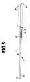
- FIG. 3shows a partly sectional view of a unit consisting of stationary shaft and slide shaft with a receiving chamber for a compression spring in the stationary shaft;
- FIG. 4shows an enlarged detail view of the receiving chamber and the compression spring
- FIG. 5shows a diagram for describing the size of the effective forward displacement force of the slide shaft in dependence upon the path of displacement.
- the bone punch 1 shown in the drawingscomprises a handgrip 2 with a connection 3 at the lower end thereof, to which a compressed air line, not shown in the drawings, can be connected.
- a motorized driveoperated by compressed air, which is not shown either, and which can be actuated by an actuating grip 4 which can be pushed into the handgrip.
- Releasably held on the handgrip 2is a unit consisting of a stationary shaft 5 and a slide shaft 6 mounted thereon for displacement in the longitudinal direction.
- the stationary shaft 5carries at its lower end a retaining hook 7 , which is open towards the distal, front end of the stationary shaft 5 and engages around a retaining bar 8 at the upper distal end of the handgrip 2 .
- This retaining bar 8forms a swivel axis for the stationary shaft 5 .
- the stationary shaft 5can be swiveled around this swivel axis between a released position in which it extends at an incline to the upper side of the handgrip 2 ( FIG.
- the stationary shaft 5extends parallel to the upper side of the handgrip 2 ( FIG. 1 ).
- the stationary shaft 5With a retaining nose 9 arranged at its lower, proximal end, engages a detent projection 10 at the upper, proximal end of the handgrip 2 , so that the stationary shaft 5 is thereby fixed on the handgrip 2 .
- the detent projection 10can be retracted by suitable means, not shown in greater detail in the drawings, so that the retaining nose 9 is released. In this way, the unit consisting of stationary shaft 5 and slide shaft 6 can be easily taken off the handgrip 2 and replaced by another unit.
- the stationary shaft 5is a rigid shaft, which extends from the handgrip 2 to its distal end and carries at its distal end a stop face 11 pointing upwards at an incline.
- Mounted on the stationary shaft 5 and guided for longitudinal displacement in a guideis the slide shaft 6 , which also extends substantially over the entire length of the stationary shaft 5 and terminates at its distal end in a cutting edge 12 , which is located opposite the stop face 11 . It is possible to cut through tissue located between the cutting edge 12 and the stop face 11 , for example, bone material, on bringing the cutting edge 12 up to the stop face 11 .
- the displacement of the slide shaft 6 along the stationary shaft 5is brought about via the motorized drive inside the handgrip 2 .
- This motorized drivedisplaces a driver 13 in the direction of the slide shaft and back.
- the driver 13projects upwards slightly above the upper side of the handgrip 2 and, extending from below through the stationary shaft, engages around the slide shaft 6 .
- This slide shaft 6carries immediately in front of and immediately behind the driver 13 lateral stop faces 14 , 15 , which abut on the driver 13 and thereby take the slide shaft 6 along with them as the driver 13 moves forwards and backwards.
- the slide shaft 6On pressing the actuating grip 4 and actuating the motorized drive, the slide shaft 6 is displaced in the distal direction.
- the driver 13is moved back into the initial position, either by the motorized drive or by suitable spring means in the handgrip, so that the slide shaft is retracted into the proximal initial position again.
- an upwardly open receiving chamber 16Arranged in the stationary shaft 5 in front of the retaining hook 7 is an upwardly open receiving chamber 16 , in which a helical spring 17 is placed.
- the helical spring 17is supported at the distal end of the receiving chamber 16 on the stationary shaft 5 , and it is shorter than the receiving chamber 16 , so that it only fills out the distal portion of the receiving chamber 16 .
- the helical spring 17may be half as long as the receiving chamber.
- a projection 18 arranged at the lower end of the slide shaft 6extends into that portion of the receiving chamber 16 which is not filled out by the helical spring 17 .
- the projection 18On displacing the slide shaft 6 forwards out of the inoperative position into the distal operative position, the projection 18 first passes through that portion of the receiving chamber which is free from the helical spring 17 and then enters into abutment on the helical spring 17 .
- the helical spring 17is compressed by this projection 18 and upon progressive displacement in the distal direction thereby exerts an increasing resetting force on the slide shaft.
- the forward displacement force of the motorized driveremains substantially constant during the entire forward displacement, so that the forward displacement force effectively displacing the slide shaft 6 in the distal direction at the beginning of the forward displacement corresponds to the forward displacement force of the motorized drive and then continuously decreases after the driver 13 enters into abutment on the helical spring 17 .
- the course of this forceis shown in FIG. 5 .
- the characteristic of the helical spring 17 placed in the receiving chamber 16is adapted to the dimensions of the respective unit consisting of stationary shaft 5 and slide shaft 6 .
- a relatively strong helical spring 17is inserted, in the case of a wider cutting edge, for example, a cutting edge of 5 millimeters in width, a considerably weaker helical spring 17 , so that the forward displacement force effectively made available at the cutting edge increases with the width of the cutting edge.
- insertion of a helical spring 17can be dispensed with entirely, for example, in the case of very wide cutting edges that have a width of 6 millimeters or so.
- each unit consisting of stationary shaft and slide shaftitself controls the forward displacement forces effectively occurring at the cutting edge, although the forward displacement force supplied by the handgrip and the motorized drive is always identical.
- the operatoris relieved of the task of adjusting the forward displacement force and, in addition, is unable to make a mistake.
Landscapes
- Health & Medical Sciences (AREA)
- Surgery (AREA)
- Life Sciences & Earth Sciences (AREA)
- Biomedical Technology (AREA)
- Medical Informatics (AREA)
- Orthopedic Medicine & Surgery (AREA)
- Oral & Maxillofacial Surgery (AREA)
- Engineering & Computer Science (AREA)
- Dentistry (AREA)
- Heart & Thoracic Surgery (AREA)
- Nuclear Medicine, Radiotherapy & Molecular Imaging (AREA)
- Molecular Biology (AREA)
- Animal Behavior & Ethology (AREA)
- General Health & Medical Sciences (AREA)
- Public Health (AREA)
- Veterinary Medicine (AREA)
- Surgical Instruments (AREA)
Abstract
Description
Claims (14)
Applications Claiming Priority (3)
| Application Number | Priority Date | Filing Date | Title |
|---|---|---|---|
| DE102007011670 | 2007-03-09 | ||
| DE102007011670ADE102007011670A1 (en) | 2007-03-09 | 2007-03-09 | Surgical bone punch |
| DE102007011670.7 | 2007-03-09 |
Publications (2)
| Publication Number | Publication Date |
|---|---|
| US20080221606A1 US20080221606A1 (en) | 2008-09-11 |
| US8197483B2true US8197483B2 (en) | 2012-06-12 |
Family
ID=39373254
Family Applications (1)
| Application Number | Title | Priority Date | Filing Date |
|---|---|---|---|
| US12/072,910Active2030-03-29US8197483B2 (en) | 2007-03-09 | 2008-02-27 | Surgical bone punch |
Country Status (6)
| Country | Link |
|---|---|
| US (1) | US8197483B2 (en) |
| EP (1) | EP1967145B1 (en) |
| JP (1) | JP5055626B2 (en) |
| AT (1) | ATE529053T1 (en) |
| DE (1) | DE102007011670A1 (en) |
| ES (1) | ES2371688T3 (en) |
Cited By (4)
| Publication number | Priority date | Publication date | Assignee | Title |
|---|---|---|---|---|
| EP3442446A4 (en)* | 2016-04-11 | 2020-03-04 | Relign Corporation | ARTHROSCOPIC DEVICES AND METHODS |
| US11172953B2 (en) | 2016-04-11 | 2021-11-16 | RELIGN Corporation | Arthroscopic devices and methods |
| US11207119B2 (en) | 2016-03-11 | 2021-12-28 | RELIGN Corporation | Arthroscopic devices and methods |
| US12167888B2 (en) | 2016-03-10 | 2024-12-17 | RELIGN Corporation | Arthroscopic devices and methods |
Families Citing this family (8)
| Publication number | Priority date | Publication date | Assignee | Title |
|---|---|---|---|---|
| DE102009008719A1 (en) | 2009-02-06 | 2010-08-12 | Aesculap Ag | Surgical sliding shaft instrument and sliding shaft |
| DE102009008687A1 (en)* | 2009-02-06 | 2010-08-12 | Aesculap Ag | Surgical sliding shaft instrument and sliding shaft |
| EP2830512B1 (en)* | 2012-03-28 | 2016-08-03 | Synthes GmbH | Bone fixation member systems |
| EP3082623B1 (en) | 2013-12-20 | 2019-11-13 | Stryker Corporation | Rongeur with cutting implement that is selectively driven by a motor so the cutting implement performs either power assisted or manual cutting of tissue |
| DE202015006833U1 (en)* | 2015-09-29 | 2015-10-22 | Christoph Zepf | Bone punch with captive punch |
| DE102017218121A1 (en) | 2017-10-11 | 2019-04-11 | Robert Bosch Gmbh | Shank for a bone punch with ceramic cutting element and manufacturing method |
| DE102017218124A1 (en) | 2017-10-11 | 2019-04-11 | Robert Bosch Gmbh | Shaft for a bone punch with longitudinally displaceable ejector |
| CN116019538B (en)* | 2023-03-29 | 2023-06-23 | 中国人民解放军联勤保障部队第九二〇医院 | Implant for high-level tibia osteotomy |
Citations (17)
| Publication number | Priority date | Publication date | Assignee | Title |
|---|---|---|---|---|
| US3752161A (en)* | 1971-08-02 | 1973-08-14 | Minnesota Mining & Mfg | Fluid operated surgical tool |
| US3835860A (en)* | 1973-06-21 | 1974-09-17 | H Garretson | Surgical bone punch |
| US4201213A (en)* | 1978-01-30 | 1980-05-06 | Codman & Shurtleff, Inc. | Surgical tool |
| US4941466A (en)* | 1987-04-13 | 1990-07-17 | Romano Jack W | Curved bore drilling method and apparatus |
| US5009661A (en)* | 1989-04-24 | 1991-04-23 | Michelson Gary K | Protective mechanism for surgical rongeurs |
| US5273519A (en)* | 1990-11-02 | 1993-12-28 | Tibor Koros | Bongeur surgical instrument |
| US5653713A (en)* | 1989-04-24 | 1997-08-05 | Michelson; Gary Karlin | Surgical rongeur |
| US5681330A (en)* | 1994-03-02 | 1997-10-28 | Ethicon Endo-Surgery, Inc. | Sterile occlusion fasteners and instrument and method for their placement |
| US5782834A (en)* | 1993-01-29 | 1998-07-21 | Smith & Nephew, Inc. | Surgical instrument |
| WO1999008604A1 (en) | 1997-08-15 | 1999-02-25 | The University Of Iowa Research Foundation | Self-clearing bone biting instrument |
| US20040102783A1 (en)* | 2002-11-27 | 2004-05-27 | Sutterlin Chester E. | Powered Kerrison-like Rongeur system |
| US20040186499A1 (en) | 1989-08-28 | 2004-09-23 | Gary Karlin Michelson | Surgical rongeur |
| DE202004015643U1 (en) | 2004-10-01 | 2004-12-09 | Aesculap Ag & Co. Kg | Surgical device in particular suitable for removal of bone tissue, comprising tool with polygonal rear end for being joined to handle |
| EP1491155A1 (en) | 2003-06-27 | 2004-12-29 | Ulrich AG | Surgical sliding shaft instrument, in particular bone and tissue punch |
| DE202004017974U1 (en) | 2004-11-19 | 2005-01-13 | Jörg Wenzler Medizintechnik GmbH | Surgical punch |
| DE102004049242A1 (en)* | 2004-10-01 | 2006-04-27 | Aesculap Ag & Co. Kg | Surgical instrument for use during bone punching, has locking button arranged at distal side of drive device and/or angle lever to prevent movement of movably supported punch when button is placed in locking position |
| US7468041B2 (en)* | 2003-06-26 | 2008-12-23 | Depuy Products, Inc. | Modular surgical instrument with reciprocable implement |
Family Cites Families (1)
| Publication number | Priority date | Publication date | Assignee | Title |
|---|---|---|---|---|
| JP2006263031A (en)* | 2005-03-23 | 2006-10-05 | Aloka Co Ltd | Ultrasonic surgery implement |
- 2007
- 2007-03-09DEDE102007011670Apatent/DE102007011670A1/ennot_activeWithdrawn
- 2008
- 2008-02-14EPEP08151399Apatent/EP1967145B1/enactiveActive
- 2008-02-14ATAT08151399Tpatent/ATE529053T1/enactive
- 2008-02-14ESES08151399Tpatent/ES2371688T3/enactiveActive
- 2008-02-27USUS12/072,910patent/US8197483B2/enactiveActive
- 2008-02-28JPJP2008047713Apatent/JP5055626B2/enactiveActive
Patent Citations (21)
| Publication number | Priority date | Publication date | Assignee | Title |
|---|---|---|---|---|
| US3752161A (en)* | 1971-08-02 | 1973-08-14 | Minnesota Mining & Mfg | Fluid operated surgical tool |
| US3835860A (en)* | 1973-06-21 | 1974-09-17 | H Garretson | Surgical bone punch |
| US4201213A (en)* | 1978-01-30 | 1980-05-06 | Codman & Shurtleff, Inc. | Surgical tool |
| US4941466A (en)* | 1987-04-13 | 1990-07-17 | Romano Jack W | Curved bore drilling method and apparatus |
| US6142997A (en)* | 1989-04-24 | 2000-11-07 | Gary Karlin Michelson | Surgical rongeur |
| US5009661A (en)* | 1989-04-24 | 1991-04-23 | Michelson Gary K | Protective mechanism for surgical rongeurs |
| US5653713A (en)* | 1989-04-24 | 1997-08-05 | Michelson; Gary Karlin | Surgical rongeur |
| US6575977B1 (en)* | 1989-04-24 | 2003-06-10 | Gary Karlin Michelson | Surgical rongeur |
| US20040186499A1 (en) | 1989-08-28 | 2004-09-23 | Gary Karlin Michelson | Surgical rongeur |
| US5273519A (en)* | 1990-11-02 | 1993-12-28 | Tibor Koros | Bongeur surgical instrument |
| US5782834A (en)* | 1993-01-29 | 1998-07-21 | Smith & Nephew, Inc. | Surgical instrument |
| US5681330A (en)* | 1994-03-02 | 1997-10-28 | Ethicon Endo-Surgery, Inc. | Sterile occlusion fasteners and instrument and method for their placement |
| WO1999008604A1 (en) | 1997-08-15 | 1999-02-25 | The University Of Iowa Research Foundation | Self-clearing bone biting instrument |
| US20040102783A1 (en)* | 2002-11-27 | 2004-05-27 | Sutterlin Chester E. | Powered Kerrison-like Rongeur system |
| US7468041B2 (en)* | 2003-06-26 | 2008-12-23 | Depuy Products, Inc. | Modular surgical instrument with reciprocable implement |
| EP1491155A1 (en) | 2003-06-27 | 2004-12-29 | Ulrich AG | Surgical sliding shaft instrument, in particular bone and tissue punch |
| DE202004015643U1 (en) | 2004-10-01 | 2004-12-09 | Aesculap Ag & Co. Kg | Surgical device in particular suitable for removal of bone tissue, comprising tool with polygonal rear end for being joined to handle |
| DE102004049242A1 (en)* | 2004-10-01 | 2006-04-27 | Aesculap Ag & Co. Kg | Surgical instrument for use during bone punching, has locking button arranged at distal side of drive device and/or angle lever to prevent movement of movably supported punch when button is placed in locking position |
| DE202004017974U1 (en) | 2004-11-19 | 2005-01-13 | Jörg Wenzler Medizintechnik GmbH | Surgical punch |
| US20060111737A1 (en)* | 2004-11-19 | 2006-05-25 | Jorg Wenzler | Surgical punching instrument |
| US7655020B2 (en)* | 2004-11-19 | 2010-02-02 | Jörg Wenzler Medizintechnik GmbH | Surgical punching instrument |
Cited By (7)
| Publication number | Priority date | Publication date | Assignee | Title |
|---|---|---|---|---|
| US12167888B2 (en) | 2016-03-10 | 2024-12-17 | RELIGN Corporation | Arthroscopic devices and methods |
| US11207119B2 (en) | 2016-03-11 | 2021-12-28 | RELIGN Corporation | Arthroscopic devices and methods |
| US12096969B2 (en) | 2016-03-11 | 2024-09-24 | RELIGN Corporation | Arthroscopic devices and methods |
| EP3442446A4 (en)* | 2016-04-11 | 2020-03-04 | Relign Corporation | ARTHROSCOPIC DEVICES AND METHODS |
| US11172953B2 (en) | 2016-04-11 | 2021-11-16 | RELIGN Corporation | Arthroscopic devices and methods |
| US11622784B2 (en) | 2016-04-11 | 2023-04-11 | RELIGN Corporation | Arthroscopic devices and methods |
| US12042167B2 (en) | 2016-04-11 | 2024-07-23 | RELIGN Corporation | Arthroscopic devices and methods |
Also Published As
| Publication number | Publication date |
|---|---|
| ES2371688T3 (en) | 2012-01-09 |
| JP2008237898A (en) | 2008-10-09 |
| EP1967145B1 (en) | 2011-10-19 |
| ATE529053T1 (en) | 2011-11-15 |
| DE102007011670A1 (en) | 2008-09-11 |
| JP5055626B2 (en) | 2012-10-24 |
| US20080221606A1 (en) | 2008-09-11 |
| EP1967145A1 (en) | 2008-09-10 |
Similar Documents
| Publication | Publication Date | Title |
|---|---|---|
| US8197483B2 (en) | Surgical bone punch | |
| USRE41265E1 (en) | Depth of drive adjustment for a fastener driving tool with removable contact member and method of exchanging contact members | |
| USRE38834E1 (en) | Safety trip assembly and trip lock mechanism for a fastener driving tool | |
| JP3927577B2 (en) | Electric bone forceps | |
| EP0273468A2 (en) | Surgical stapling instrument | |
| JP2019130328A (en) | Surgical clip applicator | |
| US7788962B2 (en) | Hydraulic tool | |
| EP2298186A3 (en) | Surgical stapling apparatus | |
| CA2500567A1 (en) | Angled surgical fastener apparatus | |
| EP1974678A3 (en) | Surgical stapling and cutting instrument with side mounted retraction member | |
| AU2003290261A1 (en) | Bone resection device | |
| WO2003030743A3 (en) | Surgical stapling device | |
| EP1990015A3 (en) | Surgical stapling and cutting instrument with manually retractable firing member | |
| EP4242057A3 (en) | Seating device | |
| JPWO2017183074A1 (en) | Manual binding tool | |
| EP3834747B1 (en) | Medical instrument | |
| WO1982000968A1 (en) | Surgical stapler drive mechanism | |
| DE102011056503B4 (en) | Actuating element for medical, preferably surgical instruments with three-finger posture | |
| CN207400775U (en) | It is ground rongeur | |
| EP3949871A1 (en) | Surgical stapling device with articulation braking assembly | |
| CN219837815U (en) | Art designing knife | |
| EP1813197A3 (en) | Surgical stapling apparatus with locking mechanism | |
| CN114147670B (en) | Stapler capable of eliminating false nails | |
| HK40082719A (en) | Clip applier shaft assembly and clip applier | |
| HK40082719B (en) | Clip applier shaft assembly and clip applier |
Legal Events
| Date | Code | Title | Description |
|---|---|---|---|
| AS | Assignment | Owner name:AESCULAP AG & CO. KG, GERMANY Free format text:ASSIGNMENT OF ASSIGNORS INTEREST;ASSIGNORS:FAULHABER, KONSTANTIN;SCHULZ, PETER;NESPER, MARKUS;AND OTHERS;REEL/FRAME:021004/0302 Effective date:20080423 | |
| AS | Assignment | Owner name:AESCULAP AG, GERMANY Free format text:CHANGE OF NAME;ASSIGNOR:AESCULAP AG & CO. KG;REEL/FRAME:021731/0524 Effective date:20080506 Owner name:AESCULAP AG,GERMANY Free format text:CHANGE OF NAME;ASSIGNOR:AESCULAP AG & CO. KG;REEL/FRAME:021731/0524 Effective date:20080506 | |
| STCF | Information on status: patent grant | Free format text:PATENTED CASE | |
| FPAY | Fee payment | Year of fee payment:4 | |
| MAFP | Maintenance fee payment | Free format text:PAYMENT OF MAINTENANCE FEE, 8TH YEAR, LARGE ENTITY (ORIGINAL EVENT CODE: M1552); ENTITY STATUS OF PATENT OWNER: LARGE ENTITY Year of fee payment:8 | |
| MAFP | Maintenance fee payment | Free format text:PAYMENT OF MAINTENANCE FEE, 12TH YEAR, LARGE ENTITY (ORIGINAL EVENT CODE: M1553); ENTITY STATUS OF PATENT OWNER: LARGE ENTITY Year of fee payment:12 |