US8197472B2 - Tissue welding and cutting apparatus and method - Google Patents
Tissue welding and cutting apparatus and methodDownload PDFInfo
- Publication number
- US8197472B2 US8197472B2US11/090,750US9075005AUS8197472B2US 8197472 B2US8197472 B2US 8197472B2US 9075005 AUS9075005 AUS 9075005AUS 8197472 B2US8197472 B2US 8197472B2
- Authority
- US
- United States
- Prior art keywords
- heating element
- jaw
- jaws
- tissue
- welding
- Prior art date
- Legal status (The legal status is an assumption and is not a legal conclusion. Google has not performed a legal analysis and makes no representation as to the accuracy of the status listed.)
- Active, expires
Links
- 238000003466weldingMethods0.000titleclaimsabstractdescription141
- 238000000034methodMethods0.000titleabstractdescription30
- 238000005520cutting processMethods0.000titledescription42
- 238000010438heat treatmentMethods0.000claimsabstractdescription415
- 230000007246mechanismEffects0.000claimsabstractdescription21
- 239000000463materialSubstances0.000claimsdescription47
- 230000000670limiting effectEffects0.000claimsdescription10
- 230000003213activating effectEffects0.000claimsdescription5
- 210000004204blood vesselAnatomy0.000abstractdescription6
- 210000001519tissueAnatomy0.000description280
- 238000003306harvestingMethods0.000description24
- 239000010935stainless steelSubstances0.000description22
- 229910001220stainless steelInorganic materials0.000description22
- 230000006870functionEffects0.000description20
- 239000004020conductorSubstances0.000description18
- 238000012546transferMethods0.000description13
- 239000000779smokeSubstances0.000description12
- 238000013461designMethods0.000description11
- 229920001296polysiloxanePolymers0.000description11
- 238000007789sealingMethods0.000description11
- 239000000919ceramicSubstances0.000description9
- 230000001105regulatory effectEffects0.000description9
- 210000003813thumbAnatomy0.000description9
- MCMNRKCIXSYSNV-UHFFFAOYSA-NZirconium dioxideChemical compoundO=[Zr]=OMCMNRKCIXSYSNV-UHFFFAOYSA-N0.000description8
- 229910010293ceramic materialInorganic materials0.000description8
- 230000009471actionEffects0.000description7
- 238000009413insulationMethods0.000description7
- 102000004169proteins and genesHuman genes0.000description7
- 230000001112coagulating effectEffects0.000description6
- 238000002224dissectionMethods0.000description6
- 210000002969egg yolkAnatomy0.000description6
- 238000010292electrical insulationMethods0.000description6
- 108090000623proteins and genesProteins0.000description6
- 238000001356surgical procedureMethods0.000description6
- 238000006073displacement reactionMethods0.000description5
- 239000006091MacorSubstances0.000description4
- 230000000740bleeding effectEffects0.000description4
- 230000015271coagulationEffects0.000description4
- 238000005345coagulationMethods0.000description4
- 208000031737Tissue AdhesionsDiseases0.000description3
- PNEYBMLMFCGWSK-UHFFFAOYSA-Naluminium oxideInorganic materials[O-2].[O-2].[O-2].[Al+3].[Al+3]PNEYBMLMFCGWSK-UHFFFAOYSA-N0.000description3
- 210000001367arteryAnatomy0.000description3
- 230000008901benefitEffects0.000description3
- 238000010276constructionMethods0.000description3
- 210000004351coronary vesselAnatomy0.000description3
- 238000009826distributionMethods0.000description3
- 210000003811fingerAnatomy0.000description3
- 230000023597hemostasisEffects0.000description3
- 208000014674injuryDiseases0.000description3
- 238000004519manufacturing processMethods0.000description3
- 229910052751metalInorganic materials0.000description3
- 239000002184metalSubstances0.000description3
- 230000036961partial effectEffects0.000description3
- 239000013618particulate matterSubstances0.000description3
- 229920000642polymerPolymers0.000description3
- 230000002829reductive effectEffects0.000description3
- 229920002379silicone rubberPolymers0.000description3
- 239000004945silicone rubberSubstances0.000description3
- 125000006850spacer groupChemical group0.000description3
- 241001460313Barbodes binotatusSpecies0.000description2
- RYGMFSIKBFXOCR-UHFFFAOYSA-NCopperChemical compound[Cu]RYGMFSIKBFXOCR-UHFFFAOYSA-N0.000description2
- 230000004913activationEffects0.000description2
- 230000003872anastomosisEffects0.000description2
- 238000013459approachMethods0.000description2
- 238000006243chemical reactionMethods0.000description2
- 239000011248coating agentSubstances0.000description2
- 238000000576coating methodMethods0.000description2
- 238000004891communicationMethods0.000description2
- 230000006835compressionEffects0.000description2
- 238000007906compressionMethods0.000description2
- 230000001276controlling effectEffects0.000description2
- 238000001816coolingMethods0.000description2
- 229910052802copperInorganic materials0.000description2
- 239000010949copperSubstances0.000description2
- 230000006378damageEffects0.000description2
- 230000003247decreasing effectEffects0.000description2
- 238000011161developmentMethods0.000description2
- 230000009977dual effectEffects0.000description2
- 239000012636effectorSubstances0.000description2
- 230000000694effectsEffects0.000description2
- 230000005611electricityEffects0.000description2
- 210000003195fasciaAnatomy0.000description2
- 230000004907fluxEffects0.000description2
- 230000002496gastric effectEffects0.000description2
- 239000002241glass-ceramicSubstances0.000description2
- 239000011810insulating materialSubstances0.000description2
- 230000010354integrationEffects0.000description2
- 238000005304joiningMethods0.000description2
- 238000003754machiningMethods0.000description2
- CPLXHLVBOLITMK-UHFFFAOYSA-Nmagnesium oxideInorganic materials[Mg]=OCPLXHLVBOLITMK-UHFFFAOYSA-N0.000description2
- 239000000395magnesium oxideSubstances0.000description2
- AXZKOIWUVFPNLO-UHFFFAOYSA-Nmagnesium;oxygen(2-)Chemical compound[O-2].[Mg+2]AXZKOIWUVFPNLO-UHFFFAOYSA-N0.000description2
- 230000013011matingEffects0.000description2
- 238000012986modificationMethods0.000description2
- 230000004048modificationEffects0.000description2
- 230000007935neutral effectEffects0.000description2
- 210000003101oviductAnatomy0.000description2
- 229910002077partially stabilized zirconiaInorganic materials0.000description2
- 210000002321radial arteryAnatomy0.000description2
- 230000009467reductionEffects0.000description2
- 239000000523sampleSubstances0.000description2
- 210000003752saphenous veinAnatomy0.000description2
- 229910000679solderInorganic materials0.000description2
- 239000000243solutionSubstances0.000description2
- 230000003685thermal hair damageEffects0.000description2
- 230000008733traumaEffects0.000description2
- 230000002792vascularEffects0.000description2
- 241000282461Canis lupusSpecies0.000description1
- 206010014561EmphysemaDiseases0.000description1
- 208000031481Pathologic ConstrictionDiseases0.000description1
- 239000004642PolyimideSubstances0.000description1
- 241000183290Scleropages leichardtiSpecies0.000description1
- 239000004809TeflonSubstances0.000description1
- 229920006362Teflon®Polymers0.000description1
- 208000027418Wounds and injuryDiseases0.000description1
- QCWXUUIWCKQGHC-UHFFFAOYSA-NZirconiumChemical compound[Zr]QCWXUUIWCKQGHC-UHFFFAOYSA-N0.000description1
- 230000002411adverseEffects0.000description1
- WYTGDNHDOZPMIW-RCBQFDQVSA-NalstonineNatural productsC1=CC2=C3C=CC=CC3=NC2=C2N1C[C@H]1[C@H](C)OC=C(C(=O)OC)[C@H]1C2WYTGDNHDOZPMIW-RCBQFDQVSA-N0.000description1
- 229910052782aluminiumInorganic materials0.000description1
- XAGFODPZIPBFFR-UHFFFAOYSA-NaluminiumChemical compound[Al]XAGFODPZIPBFFR-UHFFFAOYSA-N0.000description1
- 230000004888barrier functionEffects0.000description1
- 238000005452bendingMethods0.000description1
- 210000000013bile ductAnatomy0.000description1
- 230000015572biosynthetic processEffects0.000description1
- 238000005524ceramic coatingMethods0.000description1
- 230000008859changeEffects0.000description1
- 230000008878couplingEffects0.000description1
- 238000010168coupling processMethods0.000description1
- 238000005859coupling reactionMethods0.000description1
- 230000003292diminished effectEffects0.000description1
- 238000011038discontinuous diafiltration by volume reductionMethods0.000description1
- 201000010099diseaseDiseases0.000description1
- 208000037265diseases, disorders, signs and symptomsDiseases0.000description1
- 210000002815epigastric arteryAnatomy0.000description1
- 210000003414extremityAnatomy0.000description1
- 239000000945fillerSubstances0.000description1
- 238000001914filtrationMethods0.000description1
- -1for exampleSubstances0.000description1
- 210000000232gallbladderAnatomy0.000description1
- 238000002682general surgeryMethods0.000description1
- 230000020169heat generationEffects0.000description1
- 239000011796hollow space materialSubstances0.000description1
- 229910001119inconels 625Inorganic materials0.000description1
- 238000001746injection mouldingMethods0.000description1
- 210000003734kidneyAnatomy0.000description1
- 210000004072lungAnatomy0.000description1
- 210000001349mammary arteryAnatomy0.000description1
- 239000003550markerSubstances0.000description1
- 238000002324minimally invasive surgeryMethods0.000description1
- 238000000465mouldingMethods0.000description1
- 230000017074necrotic cell deathEffects0.000description1
- 238000013059nephrectomyMethods0.000description1
- 229910000623nickel–chromium alloyInorganic materials0.000description1
- 230000002093peripheral effectEffects0.000description1
- 229920001721polyimidePolymers0.000description1
- 239000000843powderSubstances0.000description1
- 230000008569processEffects0.000description1
- 238000010992refluxMethods0.000description1
- 238000002271resectionMethods0.000description1
- 230000002441reversible effectEffects0.000description1
- 230000035807sensationEffects0.000description1
- 238000000926separation methodMethods0.000description1
- 238000010008shearingMethods0.000description1
- 210000004872soft tissueAnatomy0.000description1
- 239000007787solidSubstances0.000description1
- 230000007480spreadingEffects0.000description1
- 238000003892spreadingMethods0.000description1
- 230000036262stenosisEffects0.000description1
- 208000037804stenosisDiseases0.000description1
- 210000002784stomachAnatomy0.000description1
- 230000000153supplemental effectEffects0.000description1
- 238000012360testing methodMethods0.000description1
- 230000000451tissue damageEffects0.000description1
- 231100000827tissue damageToxicity0.000description1
- 238000002604ultrasonographyMethods0.000description1
- 210000000626ureterAnatomy0.000description1
- 238000007879vasectomyMethods0.000description1
- 210000003462veinAnatomy0.000description1
- 238000013022ventingMethods0.000description1
- 230000000007visual effectEffects0.000description1
- 238000012800visualizationMethods0.000description1
- 229910001233yttria-stabilized zirconiaInorganic materials0.000description1
- RUDFQVOCFDJEEF-UHFFFAOYSA-Nyttrium(III) oxideInorganic materials[O-2].[O-2].[O-2].[Y+3].[Y+3]RUDFQVOCFDJEEF-UHFFFAOYSA-N0.000description1
- 229910052726zirconiumInorganic materials0.000description1
Images


Classifications
- A—HUMAN NECESSITIES
- A61—MEDICAL OR VETERINARY SCIENCE; HYGIENE
- A61B—DIAGNOSIS; SURGERY; IDENTIFICATION
- A61B18/00—Surgical instruments, devices or methods for transferring non-mechanical forms of energy to or from the body
- A61B18/04—Surgical instruments, devices or methods for transferring non-mechanical forms of energy to or from the body by heating
- A61B18/08—Surgical instruments, devices or methods for transferring non-mechanical forms of energy to or from the body by heating by means of electrically-heated probes
- A61B18/082—Probes or electrodes therefor
- A61B18/085—Forceps, scissors
- A—HUMAN NECESSITIES
- A61—MEDICAL OR VETERINARY SCIENCE; HYGIENE
- A61B—DIAGNOSIS; SURGERY; IDENTIFICATION
- A61B17/00—Surgical instruments, devices or methods
- A61B17/28—Surgical forceps
- A61B17/29—Forceps for use in minimally invasive surgery
- A—HUMAN NECESSITIES
- A61—MEDICAL OR VETERINARY SCIENCE; HYGIENE
- A61B—DIAGNOSIS; SURGERY; IDENTIFICATION
- A61B18/00—Surgical instruments, devices or methods for transferring non-mechanical forms of energy to or from the body
- A61B18/04—Surgical instruments, devices or methods for transferring non-mechanical forms of energy to or from the body by heating
- A61B18/12—Surgical instruments, devices or methods for transferring non-mechanical forms of energy to or from the body by heating by passing a current through the tissue to be heated, e.g. high-frequency current
- A61B18/14—Probes or electrodes therefor
- A61B18/1442—Probes having pivoting end effectors, e.g. forceps
- A61B18/1445—Probes having pivoting end effectors, e.g. forceps at the distal end of a shaft, e.g. forceps or scissors at the end of a rigid rod
- A—HUMAN NECESSITIES
- A61—MEDICAL OR VETERINARY SCIENCE; HYGIENE
- A61B—DIAGNOSIS; SURGERY; IDENTIFICATION
- A61B17/00—Surgical instruments, devices or methods
- A61B2017/00017—Electrical control of surgical instruments
- A61B2017/00022—Sensing or detecting at the treatment site
- A61B2017/00084—Temperature
- A—HUMAN NECESSITIES
- A61—MEDICAL OR VETERINARY SCIENCE; HYGIENE
- A61B—DIAGNOSIS; SURGERY; IDENTIFICATION
- A61B17/00—Surgical instruments, devices or methods
- A61B17/00234—Surgical instruments, devices or methods for minimally invasive surgery
- A61B2017/00353—Surgical instruments, devices or methods for minimally invasive surgery one mechanical instrument performing multiple functions, e.g. cutting and grasping
- A—HUMAN NECESSITIES
- A61—MEDICAL OR VETERINARY SCIENCE; HYGIENE
- A61B—DIAGNOSIS; SURGERY; IDENTIFICATION
- A61B17/00—Surgical instruments, devices or methods
- A61B17/00491—Surgical glue applicators
- A61B2017/00504—Tissue welding
- A—HUMAN NECESSITIES
- A61—MEDICAL OR VETERINARY SCIENCE; HYGIENE
- A61B—DIAGNOSIS; SURGERY; IDENTIFICATION
- A61B17/00—Surgical instruments, devices or methods
- A61B17/28—Surgical forceps
- A61B17/29—Forceps for use in minimally invasive surgery
- A61B17/2909—Handles
- A61B2017/2912—Handles transmission of forces to actuating rod or piston
- A—HUMAN NECESSITIES
- A61—MEDICAL OR VETERINARY SCIENCE; HYGIENE
- A61B—DIAGNOSIS; SURGERY; IDENTIFICATION
- A61B17/00—Surgical instruments, devices or methods
- A61B17/28—Surgical forceps
- A61B17/29—Forceps for use in minimally invasive surgery
- A61B2017/2926—Details of heads or jaws
- A61B2017/2932—Transmission of forces to jaw members
- A61B2017/2933—Transmission of forces to jaw members camming or guiding means
- A61B2017/2936—Pins in guiding slots
- A—HUMAN NECESSITIES
- A61—MEDICAL OR VETERINARY SCIENCE; HYGIENE
- A61B—DIAGNOSIS; SURGERY; IDENTIFICATION
- A61B17/00—Surgical instruments, devices or methods
- A61B17/28—Surgical forceps
- A61B17/29—Forceps for use in minimally invasive surgery
- A61B2017/2926—Details of heads or jaws
- A61B2017/2945—Curved jaws
- A—HUMAN NECESSITIES
- A61—MEDICAL OR VETERINARY SCIENCE; HYGIENE
- A61B—DIAGNOSIS; SURGERY; IDENTIFICATION
- A61B17/00—Surgical instruments, devices or methods
- A61B17/34—Trocars; Puncturing needles
- A61B17/3417—Details of tips or shafts, e.g. grooves, expandable, bendable; Multiple coaxial sliding cannulas, e.g. for dilating
- A61B17/3421—Cannulas
- A61B2017/3445—Cannulas used as instrument channel for multiple instruments
- A—HUMAN NECESSITIES
- A61—MEDICAL OR VETERINARY SCIENCE; HYGIENE
- A61B—DIAGNOSIS; SURGERY; IDENTIFICATION
- A61B18/00—Surgical instruments, devices or methods for transferring non-mechanical forms of energy to or from the body
- A61B18/04—Surgical instruments, devices or methods for transferring non-mechanical forms of energy to or from the body by heating
- A61B18/12—Surgical instruments, devices or methods for transferring non-mechanical forms of energy to or from the body by heating by passing a current through the tissue to be heated, e.g. high-frequency current
- A61B18/14—Probes or electrodes therefor
- A61B2018/1405—Electrodes having a specific shape
- A61B2018/1425—Needle
- A61B2018/1432—Needle curved
- A—HUMAN NECESSITIES
- A61—MEDICAL OR VETERINARY SCIENCE; HYGIENE
- A61B—DIAGNOSIS; SURGERY; IDENTIFICATION
- A61B90/00—Instruments, implements or accessories specially adapted for surgery or diagnosis and not covered by any of the groups A61B1/00 - A61B50/00, e.g. for luxation treatment or for protecting wound edges
- A61B90/03—Automatic limiting or abutting means, e.g. for safety
Definitions
- the present inventionrelates to surgical devices and methods for severing and sealing blood vessels and, in particular, to an endoscopic tissue welder.
- CABGCoronary Artery Bypass Grafting
- Vessel harvestinginvolves liberating the vessel from surrounding tissue and transecting smaller side branches, cauterizing, tying or ligating the vessel at a proximal site and a distal site, and then transecting the vessel at both sites before it is removed from the body.
- Such devicestypically comprise a pair of tweezers, jaws or forceps that grasp onto and hold tissue therebetween.
- the devicesmay operate with a heating element in contact with the tissue, with an ultrasonic heater that employs frictional heating of the tissue, or with a mono- or bi-polar electrode heating system that passes current through the tissue such that the tissue is heated by virtue of its own electrical resistance.
- the devicesheat the tissue to temperatures such that the tissue is either “cut” or “sealed”, as follows.
- tissue weldingrefers to procedures that cause otherwise separated tissue to be sealed, coagulated, fused, welded or otherwise joined together. Numerous devices employing the same general principle of controlled application of a combination of heat and pressure can be used to join or “weld” adjacent tissues to produce a junction of tissues or an anastomosis of tubular tissues.
- Monopolar and bipolar probes, forceps or scissorsuse high frequency electrical current that passes through the tissue to be coagulated.
- the current passing through the tissuecauses the tissue to be heated, resulting in coagulation of tissue proteins.
- the currentleaves the electrode and after passing through the tissue, returns to the generator by means of a “ground plate” which is attached or connected to a distant part of the patient's body.
- the electric currentpasses between two electrodes with the tissue being placed or held between the two electrodes as in the “Kleppinger bipolar forceps” used for occlusion of Fallopian tubes.
- There are many examples of such monopolar and bipolar instrumentscommercially available today from companies including Valley Lab, Cabot, Meditron, Wolf, Storz and others worldwide.
- a new development in this areais the “Tripolar” instrument marketed by Cabot and Circon-ACMI which incorporates a mechanical cutting element in addition to monopolar coagulating electrodes.
- a similar combined sealing and mechanical cutting devicemay also be known as a tissue “bisector,” which merges the terms bipolar cautery and dissector.
- tissue bisectoris packaged for sale as an element of the VASOVIEW® Uniport Plus and VASOVIEW® 5 vessel harvesting systems by Guidant Corporation of Santa Clara, Calif.
- ultrasonic tissue heatersIn ultrasonic tissue heaters, a very high frequency (ultrasonic) vibrating element or rod is held in contact with the tissue. The rapid vibrations generate heat causing the proteins in the tissue to become coagulated.
- Conductive tissue weldersusually include jaws that clamp tissue therebetween, one or both of which are resistively heated. In this type of instrument, no electrical current passes through the tissue, as is the case for monopolar or bipolar cautery. Some tissue welders also perform a severing function without a mechanical knife.
- the Thermal Ligating Shears made by Starion Instruments of Saratoga, Calif.is a, hand activated instrument that utilizes thermal welding to simultaneously seal and divide soft tissue during laparoscopic general surgery procedures.
- the Starion deviceuses a heating element at the tip of one of a pair of facing jaws combined with pressure to denature the protein molecules within the tissue. The denatured proteins bond together, forming an amorphous mass of protein, and fusing tissue layers together.
- the procedurecan be used to fuse vessels closed. More highly focused heat may be applied in the center of the tissue within the jaws of the instrument, causing the tissue or vessel to divide, thus resulting in two sealed ends.
- a description of the Starion deviceis provided at www.starioninstruments.com.
- the present inventionprovides designs of tissue severing/sealing devices that control heat distribution within the distal jaws.
- multiple heating elementsare provided on one of the jaws of a tissue welding device.
- a primary heating elementis positioned along the midline of the jaw length and is electrically connected to two secondary heating elements, one on each side of the primary heater. Electrical current passes through the primary heater and is then divided equally between the two secondary heaters.
- the electrical resistances of the three heating elementsare designed such that the primary heater has the highest power dissipation (i.e., reaches the highest temperature), while the two secondary heaters have equal power dissipation but lower than that of the primary heater. This has the effect that the primary heater cuts tissue, while the secondary heaters seal or weld tissue.
- the three heating elementsare separated by electrical insulation along their working lengths to prevent inadvertent contact, for example an air gap, silicone, or other such insulation.
- the present inventionprovides a surgical apparatus for welding and severing tissue, comprising an elongated shaft having first and second relatively movable elongated jaws having jaw-facing surfaces attached to a distal end thereof.
- a first heating element for welding tissue and a second heating element for severing tissueare provided on the jaw-facing surface of the first jaw.
- the first heating elementis adapted to heat up to a first temperature upon application of power, while the second heating element is adapted to heat up to a second temperature greater than the first temperature upon application of power so that the first heating element welds tissue while the second heating element cuts tissue.
- the first heating elementhas a lower electrical resistance than the second heating element.
- the first heating elementpreferably has a wider profile than the second heating element in a plane transverse to the direction of elongation of the first jaw.
- the first heating elementhas a lower profile relative to the second heating element in a direction toward the second jaw.
- the second heating elementextends generally centrally along the jaw-facing surface of the first jaw, and the first heating element comprises at least two welding members, one each on either side of the second heating element.
- the two welding membersmay be formed by a bifurcated segment of a one-piece heating element, the separated portions in the bifurcated segment being connected in parallel to a source of power.
- the first and second heating elementsare desirably connected in series to a common source of power such that a current passing through one of the pair of welding members is about one half the current passing through the second heating element.
- each of the welding memberscomprises a strip of material having a generally flat jaw-facing surface defining a lateral width
- the second heating elementdefines a cylindrical jaw-facing surface having a lateral width smaller than that of either of the welding members.
- the second jawmay not include heating elements such that the first jaw is a “hot” jaw, and the second jaw is a “cold” jaw.
- a third heating element for welding tissuemay also be provided on the jaw-facing surface of the first jaw.
- the third heating elementis adapted to heat up to a temperature that is also lower than the second temperature (i.e., lower than a cutting temperature), and desirably to the first temperature, upon application of power.
- a control handleis connected to a proximal end of the elongated shaft and has a control actuator mounted thereon for alternately separating and bringing together the jaw-facing surfaces of the elongated jaws.
- a force-limiting interface between the control actuator and the elongated jawslimits the magnitude of closing force of the jaws.
- the first jawcomprises a ceramic material having a thermal conductivity of less than 5.0 W/m-K.
- the first jawmay comprise an inner member covered with the ceramic material.
- the inner member of the first jawdoes not form a part of any electrical conduction path leading to either the first or second heating elements.
- the apparatusmay further include a heat sink provided on the jaw-facing surface of one of the first or second jaws and positioned to influence lines of heat flux to remain within the jaws, and thermal insulation provided on the outboard side(s) of the heat sink.
- the present inventionalso provides a surgical apparatus for welding and severing tissue, comprising first and second relatively movable elongate jaws having jaw-facing surfaces and an elongated shaft having the first and second relatively movable jaws attached to a distal end thereof.
- a first heating element for welding tissueis provided on the jaw-facing surface of one of the first or second jaws.
- a second heating element for severing tissueis provided on the jaw-facing surface of one of the first or second jaws.
- An electrical circuit path within the surgical apparatusincludes a portion extending along the elongated shaft and through the first and second heating elements in series. Upon application of current through the electrical circuit path, the first heating element heats up to a first temperature and the second heating element heats up to a second temperature greater than the first temperature, so that the first heating element welds tissue while the second heating element cuts tissue.
- the second heating elementis provided on the jaw-facing surface of the second jaw, wherein the first heating element has a wider profile than the second heating element in a plane transverse to the direction of elongation of the first jaw.
- the first heating elementdesirably has a lower electrical resistance than the second heating element.
- a control handleis connected to a proximal end of the elongated shaft and has a control actuator mounted thereon for alternately separating and bringing together the jaw-facing surfaces of the elongated jaws. A force-limiting interface between the control actuator and the elongated jaws limits the magnitude of closing force of the jaws.
- Another aspect of the present inventionis a surgical method of severing a target tissue while welding the severed ends.
- the methodincludes providing a surgical apparatus for welding and severing tissue including a pair of jaws adapted to open and close upon the target tissue, the jaws including first and second resistive heating elements.
- the jawsare closed upon target tissue and the first heating element is energized to a first temperature and for a sufficient period of time to form a welded region in the target tissue.
- the second heating elementis also energized to a second temperature greater than the first temperature to sever the target tissue within the welded region.
- step of electrically energizing the second heating elementis performed after forming the weld in the target tissue.
- the target tissueis a target vessel
- the step of closingcomprises transversely closing the jaws upon the target vessel.
- a still further aspect of the present inventionis a surgical apparatus for welding and severing tissue, comprising first and second relatively movable elongated jaws having jaw-facing surfaces.
- An elongated shaftsupports the first and second relatively movable the jaws at a distal end thereof.
- An energy applicatoris provided on the jaw-facing surface of the first jaw.
- the first jawcomprises a ceramic material having a thermal conductivity of less than 5.0 W/m-K to help reduce the amount of heat generated by the energy applicator that is lost to the jaws.
- the first jawmay consist essentially of the ceramic material, or may include an inner member covered with the ceramic material.
- the inner member of the first jawdoes not form a part of any electrical conduction path leading to the energy applicator.
- the ceramic materialmay be selected from the group consisting of: alumina; machinable glass ceramic; zirconia; yttria; and partially stabilized zirconia.
- Another aspect of the inventionis a surgical apparatus for welding and severing tissue, comprising an elongated shaft having first and second relatively movable elongated jaws having jaw-facing surfaces attached to a distal end thereof.
- a first heating elementis provided on the jaw-facing surface of the first jaw, and is adapted to heat up to a first temperature upon application of power.
- the first heating elementis made of or is placed in electrical series contact with a temperature regulating material whose electrical resistance is not constant over a predetermined temperature range including the first temperature.
- the temperature regulating materialis a Positive Temperature Coefficient of Resistance (PTCR) material having an electrical resistance that will increase with increasing temperature such that the rate of temperature increase upon application of power slows down as the temperature of the temperature regulating material nears the first temperature.
- PTCRPositive Temperature Coefficient of Resistance
- the temperature regulating materialis a Polymer Positive Temperature Coefficient (PPTC) material having an electrical resistance that rapidly increases as the temperature of the temperature regulating material nears the first temperature.
- the apparatusmay include a circuit that loops through the first heating element and through a device made of the temperature regulating material.
- the temperature regulating materialis formed into a rod-like element which is surrounded by a tubular layer of electrical insulation, and wherein the first heating element comprises an outer tube closely surrounding the electrical insulation.
- a surgical apparatus for welding and severing tissuecomprising an elongated shaft having first and second relatively movable elongated jaws having jaw-facing surfaces attached to a distal end thereof.
- An energy applicator for welding tissueis provided on the jaw-facing surface of the first jaw, and a fasciotomy cutter is provided on one of the jaws.
- the fasciotomy cuttercomprises a knife blade on an exterior surface of one of the jaws.
- the energy applicatorcomprises a first heating element for welding tissue provided on the jaw-facing surface of the first jaw and adapted to heat up to a first temperature upon application of power
- the fasciotomy cuttercomprises an extension of the first heating element that wraps around a distal tip of the first jaw.
- the first jawmay comprise a longitudinal main portion and a sloped distal end and wherein the first heating element extends along the main portion and then slopes downward to the distal end.
- the fasciotomy cuttercomprises a narrowed portion of the first heating element at the sloped distal end of the first jaw.
- the sloped distal end of the first jawcomprises a pronounced rib around which the first heating element conforms.
- the fasciotomy cuttercomprises a heating element provided on one of the jaws and supplied with power through a different circuit than the energy applicator.
- Another aspect of the inventionis a surgical apparatus for welding and severing tissue, comprising first and second relatively movable elongate jaws having jaw-facing surfaces that are provided on the distal end of an elongated shaft.
- An energy applicator for welding tissueis provided on the jaw-facing surface of the first jaw, and a resistance welder is provided on one of the jaws.
- the energy applicatorcomprises a first heating element for welding tissue provided on the jaw-facing surface of the first jaw and adapted to heat up to a first temperature upon application of power
- the resistance weldercomprises an extension of the first heating element that wraps around a distal tip of the first jaw.
- the resistance welderhas a surface area per length that is larger than the surface area per length of the first heating element for welding tissue.
- the resistance weldercomprises a heating element provided on one of the jaws and supplied with power through a different circuit than the energy applicator.
- FIGS. 1A-1Care perspective views of a modular handle unit of a vessel harvesting system including a sled/adapter that permits a multipurpose handle base of the system to receive a tissue severing/welding device of the present invention
- FIGS. 2A-2Bare perspective views of the distal end of an exemplary tissue severing/welding device of the present invention showing a pair of clamping jaws in their closed position;
- FIGS. 3A-3Bare perspective views of the distal end of the tissue severing/welding device of FIGS. 2A-2B showing the clamping jaws in their open position;
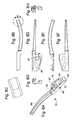
- FIG. 4is an exploded perspective view of the distal end of the tissue severing/welding device of FIGS. 2A-2B ;
- FIGS. 5A-5Bare perspective views of a “hot” jaw used in the exemplary tissue severing/welding device of the present invention.
- FIGS. 6A-6Bare enlarged perspective views of a proximal subassembly of the “hot” jaw of FIGS. 5A-5B ;
- FIGS. 7A-7Care perspective views of an exemplary heating element subassembly of the “hot” jaw of FIGS. 5A-5B ;
- FIGS. 8A-8Hare perspective, plan, and elevational views of an exemplary inner jaw forming a portion of the “hot” jaw of FIGS. 5A-5B ;
- FIGS. 9A-9Eare perspective, plan, and elevational views of an exemplary heating element for welding tissue used in the “hot” jaw of FIGS. 5A-5B ;
- FIGS. 10A-10Hare perspective, plan, and elevational views of an exemplary boot for covering the inner jaw of FIGS. 8A-8H ;
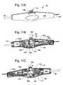
- FIG. 11Ais a perspective view of a proximal control handle of an exemplary tissue severing/welding device of the present invention.
- FIGS. 11B-11Care opposite longitudinal sectional views of the control handle of FIG. 11A including a passive smoke filter therein;
- FIGS. 11D-11Fillustrate control handles having alternative smoke filter configurations
- FIG. 12is a perspective exploded view of the proximal control handle of FIG. 11A ;
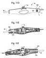
- FIG. 13Ais a perspective view of an alternative control handle of the present invention.
- FIGS. 13B-13Care opposite longitudinal sectional views of the control handle of FIG. 13A ;
- FIGS. 14A-14Care elevational views of pair of jaws in open and closed positions that illustrate a preferred jaw opening mechanism of the present invention
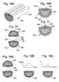
- FIG. 15illustrates in cross-section a “hot” jaw spaced from a “cold” jaw similar to those shown in FIGS. 5A-5B ;
- FIGS. 16A-16Bshow variations on the “hot” jaw of FIG. 15 ;
- FIG. 17illustrates another possible variation on a hot jaw of the present invention having only one heating element and a conductive plate for absorbing heat and welding tissue;
- FIGS. 18A-18Cillustrate alternative jaw configurations in cross-section that again includes multiple heating elements distributed on both jaws
- FIGS. 19A-19Eillustrate an exemplary jaw including an inner jaw of a low thermal conductivity material
- FIG. 20illustrates a longitudinal cross-section of a “hot” jaw of the prior art
- FIGS. 21A-21Eillustrate a number of alternative jaw cross-sections that reduce the amount of heat lost to the inner jaw
- FIGS. 22A and 22Bschematically illustrate two different sets of jaws having tissue clamping plates thereon and either a single or dual heating elements electrically connected in parallel;
- FIG. 23illustrates another sample test set up with a single heater on a lower jaw and no heater on an upper jaw
- FIGS. 24A-24Cillustrate three different alternative embodiments of tissue welding jaws that incorporate a material within the boots and adjacent the heating element that provide a “hot zone” for welding;
- FIG. 25illustrates a still further alternative embodiment of the present invention with multiple heating elements concentrically arranged in a hot jaw
- FIGS. 26A and 26Bare schematic views of an exemplary tissue welder having a fasciotomy cutter
- FIG. 27is a side elevational view of the distal tips of upper and lower jaws having a fasciotomy heater wire on a leading edge and angled toward one another such that when the jaws are closed they guide the facia toward the heater wire;
- FIG. 28illustrates a pair of tissue welding jaws having a fasciotomy cutter comprising a knife edge or blade longitudinally disposed on a midline of an outer surface of one of the jaws;
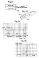
- FIG. 29is a graph of the temperature of a tissue welder heating element over time
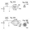
- FIGS. 31A and 31Bschematically illustrate a circuit having a heating element and a PPTC device electrically connected in series therewith;
- FIGS. 32A and 32Billustrate a rod-like PPTC element concentrically arranged within an outer tubular heating element with a tubular layer of electrical insulation therebetween;
- FIGS. 33A-33Cillustrate a system which actively monitors and controls the temperature of tissue within the jaws of the thermal tissue welding device of the present invention.
- FIGS. 34-37illustrate a number of designs of tissue welder jaws having localized heaters on the distal end of one of the jaws.
- devices and methods for sealing, or coagulating, and severing tissue during surgeryincorporate means for controllably heating tissue while simultaneously applying a definite and controllable amount of pressure to the tissue being heated. Because of the combined application of heat and pressure, tissue proteins will become coagulated and blood vessels within the tissue will be sealed shut, achieving hemostasis.
- Optimal sealing or coagulating tissuemeans producing a strong and durable seal or coagulation or anastomosis with a minimal amount of collateral tissue damage.
- One aspect of the present inventionincludes a method and system for the surgical treatment of biological tissue, wherein thermal energy and pressure are applied simultaneously, substantially simultaneously, consecutively, or alternatively, over a time such that tissue proteins are denatured and the tissue will adhere or join to itself or to other tissues, for the purpose of coagulating bleeding, sealing tissue, joining tissue and cutting tissue.
- thermal energy and pressureare applied simultaneously, substantially simultaneously, consecutively, or alternatively, over a time such that tissue proteins are denatured and the tissue will adhere or join to itself or to other tissues, for the purpose of coagulating bleeding, sealing tissue, joining tissue and cutting tissue.
- the devices of the inventionmay also incorporate means for cutting, or severing the tissue.
- Severingincludes dissecting or tissue division, tissue disruption or separation, plane development, or definition, or mobilization of tissue structures in combination with a coagulation, or hemostasis or sealing of blood vessels or other tissue structures such as lymphatics, or tissue joining. Severing can be achieved by use of amounts of heat greater than the amount required to coagulate the tissues, yet a minimum amount of energy is used with the least amount of unwanted tissue necrosis.
- severingcan be achieved by other mechanical, ultrasonic, or electronic means, including, but not limited to, shearing action, laser energy, and RF, or a combination of two or more of the above. For example, a blade may be passed through the coagulated tissue while the tissue is being held in the jaws of the instrument.
- the present inventiondesirably provides a tissue welder that can be incorporated as a component of an integrated vessel harvesting system, such as is disclosed in application Ser. No. 10/951,426, filed Sep. 28, 2004, which is expressly incorporated herein by reference.
- the vessel harvesting systemis especially useful in minimally invasive endoscopic harvesting of blood vessels, including harvesting of internal thoracic artery, or vessels of the extremities along the radial artery in the arm for use in coronary artery bypass grafting, and the saphenous vein in the leg for use in both coronary artery bypass grafting and peripheral artery bypass.
- the tissue welderperforms both a severing and securing/welding function in separating side branches from the target vessel that is being harvested. It should be understood, however, that various aspects of the tissue welder described herein may be utilized in conjunction with other surgical systems for coagulating and/or dissecting tissue.
- the exemplary embodiment of the tissue welder of the present inventioncomprises a so-called “welding and severing device” that is used to close off and separate side branches from a primary vessel being harvested, and also possibly to sever the primary vessel.
- the deviceis disclosed herein are suitable for welding and severing tissue in general not just vessels.
- tissue welding and severing devicerefers to any and all devices that accomplish a single function or any combination of the functions of welding, ligating, cauterizing, coagulating and/or sealing, and severing or transecting target tissue.
- electrocautery toolssuch as bipolar scissors (or other plural electrode-based devices), monopolar devices, tissue bisectors, or other such devices provide these functions alone or in conjunction with an integral blade or cutter.
- Other similar devices using various acceptable sources of energy for sealing the tissuefor example, RF, microwave, laser, ultrasound, direct thermal energy, etc.
- Each device that acts on tissue to either weld or sever itwill be termed an energy applicator.
- the welding and severing devicecould be a single tool or a combination of plurality of separate tools each having its own function useful in tissue severing, or more specifically in vessel harvesting.
- tissue welding devices and methodsmay be implemented using heating and control structures other than those disclosed herein, and in the context of systems other than those for vessel harvesting.
- tissue welder disclosed hereinmay be utilized with other welding and severing devices, such as bipolar scissors or tissue bisectors.
- certain aspects of the coagulation function of the tissue weldermay be combined with a mechanical cutter to provide the severing function.
- tissue welders and features described hereinhave numerous applications in addition to vessel harvesting.
- a tissue weldermay be utilized in gastric bypass surgery to resect and close a portion of the stomach.
- volume reduction of the lungs in patients with emphysemacan also be accomplished with the devices disclosed herein. Bowel resection is another potential application.
- FIGS. 1A-1Cillustrate a modular handle unit 20 of an exemplary vessel harvesting system comprising a mating handle base 22 and handle sled 24 .
- the handle base 22includes a distal flange 26 secured to an elongated cannula 28 .
- the cannula 28is sized to extend into a body cavity and provides a channel for various vessel harvesting tools.
- the handle sled 24includes structure for mating with the handle base 22 , as seen in FIG. 1A .
- Various modular handle units and vessel harvesting systemsare illustrated and described in aforementioned application Ser. No. 10/951,426, filed Sep. 28, 2004.
- FIG. 1Calso illustrates an enlarged distal end of the cannula 28 through which a distal end of the tissue severing/welding device 30 projects.
- the device 30comprises a pair of relatively movable elongated jaws 40 , 42 on its distal end, which are shown open.
- a mechanism within the handle 38includes an actuator 44 for opening and closing the jaws 40 , 42 .
- the jaws 40 , 42are elongated generally in a proximal-distal direction such that they are much longer in that direction than in either orthogonal or transverse axis.
- jawrefers to a member that may be brought together with another similar member or other structure such that jaw-facing surfaces on both members are brought into contact or close proximity.
- a jawmay be provided on a clamp, tweezers, forceps, or similar grasping tools.
- the jaws 40 , 42are mounted such that their proximal ends are journalled about common or different but closely spaced pivots and their distal ends open and close. Of course, the jaws may be mounted for parallel movement instead of in a pivoting action.
- An exemplary embodiment of the present inventionincludes a “hot” jaw and a “cold” jaw, the difference being that only one jaw is actively heated. It should be emphasized, however, that certain aspects of the present invention are applicable to different jaw configurations, such as both being “hot” jaws, or both being “cold” jaws with a separate source of heat.
- the first jaw 40comprises a “hot” jaw, while the second jaw 42 is a “cold” jaw.
- the term “hot”refers to the presence of at least one active heating element thereon, while a “cold” jaw provides no active heating (but may become hot from indirect heating by the other jaw).
- the first or “hot” jaw 40includes a first heating element 46 for welding tissue and a second heating element 48 for severing tissue.
- the first heating element 46is adapted to heat up to a first temperature upon application of current therethrough, while the second heating element 48 is adapted to heat up to a second temperature upon application of current therethrough which is greater than the first temperature.
- first heating element 46heats up to within a welding temperature zone but not to a cutting temperature threshold
- second heating element 48heats up past the welding temperature zone into the cutting temperature zone.
- the relative electrical resistance values of the first and second heating elements 46 , 48may be such that they heat up to different temperatures.
- the materials usedmay be the same, but the first and second heating elements 46 , 48 may be shaped in a manner that causes their differential heating.
- the current passed through the two heating elementsmay be unequal.
- FIG. 1Calso basically illustrates a preferred configuration of the jaws 40 , 42 and a distal end of the shaft 36 extending through a distal end of the elongated cannula 28 .
- the jaws 40 , 42are arranged to pivot apart about a common axis, represented by pivot pin 50 .
- An exemplary mechanism for opening and closing the jaws 40 , 42will be described in detail below.
- Each of the jaws 40 , 42includes an inner jaw member of rigid material and a boot 52 a , 52 b (as seen in FIG. 3A ) surrounding the inner jaw member that is made of the material that resists tissue adhesions during operation of the device.
- the inner jaw membersare made of stainless steel, but other materials that provide less of a heat sink may be used.
- the boots 52 a , 52 bare made of a heat-resistant silicone rubber.
- the boots 52 a , 52 balso provide some thermal insulation around the inner jaw members to reduce heat losses thereto.
- the first and second heating elements 46 , 48are arranged external to the boot 52 a on the first jaw 40 , in particular on a surface of the jaw that faces the other jaw.
- FIGS. 2-7provide a number of assembled, exploded, and other partial views of the distal end of an exemplary tissue welding and severing device 30 of the present invention.
- the jaws 40 , 42are shown closed at the distal end of the welding and severing device 30 .
- the device 30includes a generally tubular distal tip 54 that fits on the end of the device shaft 36 and houses a mechanism (described below) for opening and closing the jaws 40 , 42 .
- Both jaws 40 , 42exhibit a shallow curvature along their lengths such that their jaw-facing surfaces contact along a curved line.
- the entire distal assembly of the device 30 including the jaws 40 , 42is sized to fit through a 5 mm diameter port, thus enabling use in minimally invasive surgery.
- the jaws 40 , 42preferably incorporate a multiple heater welding system on a “hot” jaw 40 .
- at least two heating elementare provided, with one heating element adapted to sever tissue and a second heating element adapted to weld or coagulate tissue.
- the jaw 40incorporates a “tri-heater” arrangement with one heating element for cutting and two heating elements for welding disposed on either side of the cutter.
- the heating elementsextend longitudinally from a proximal to a distal end of the jaw 40 , with the cutter generally centrally located and the two welders symmetrically located on either side.
- FIGS. 3A-3Billustrate the jaws 40 , 42 in their open configuration.
- the first heating element 46is preferably bifurcated into two welding members separated laterally, with a single second heating element 48 provided therebetween.
- the bifurcated welding members of the first heating element 46each provide a weld region within the tissue, while the second heating element 48 cuts the tissue within the weld region.
- the hot jaw 40includes three heating elements: a central cutting element and two adjacent welding elements. Although the exemplary embodiment combines the two adjacent welding elements in a single piece, they could easily be constructed separately.
- one or both jaws 40 , 42include inner jaw members surrounded by a boot 52 a , 52 b .
- the boot 52 b around the second jaw 42is preferably provided with a series of lateral serrations 60 that facilitate gripping and prevent slipping of the tissue when clamped between the jaws. Because of the presence of the first and second heating elements 46 , 48 on the exterior of the boot 52 a on the first jaw 40 , no serrations are necessary.
- FIG. 4shows the components of the distal end of the device 30 exploded, while FIGS. 5-7 best illustrate the specific shapes and subassembly of the first and second heating elements 46 , 48 , and how they mount on and cooperate with the first jaw 40 .
- the inner jaw member 62 (seen isolated in FIGS. 8A-8H ) of the first or “hot” jaw 40comprises an elongated and curved distal portion 64 and a proximal pivot housing 66 , including through holes for pivotal movement with respect to the other jaw. More specifically, the proximal pivot housing 66 of the inner jaw member 62 includes a large circular through hole 67 and an angled slot 68 , both formed in an outer wall section 69 . A pair of sidewalls 70 upstanding from the outer wall section 69 provide a space on the inner side of the pivot housing 66 within which electrical wires and a pivot mechanism are received, as explained below.
- the first heating element 46comprises a proximal crimp 72 and flange 73 .
- Two elongated welding members 74extend from the proximal crimp and flange in a distal direction and curl back upon themselves to terminate at a common barb 75 (see FIG. 7B ).
- the elongated welding members 74preferably comprise thin, rectangular strips each having a lateral width W that extend in parallel across a spaced distance S. Because the welding members 74 are connected at their proximal ends by the crimp 72 and flange 73 structure, and at their distal ends by the common barb 75 , they define a bifurcated portion of the first heating element 46 .
- the first heating element 46comprises a single, homogeneous piece of metal (e.g., stainless steel) that has been formed into the illustrated shape by stamping, bending, machining, etc.
- the second heating element 48extends between and in parallel with the spaced welding members 74 and is separated therefrom by air gaps.
- the heating element 48also extends in a distal direction the same length as the welding member 74 and curls back upon itself to terminate at a connection end 76 adjacent the barb 75 (see FIG. 7B ).
- the connection end 76 and barb 75are electrically connected using a resistance or spot weld, for example.
- resistance weldused to describe the joint between two mechanical parts encompasses all suitable varieties of such joints, including for example, spot welds, laser welds, soldered joints, brazed joints, etc.
- the heating element 48may comprise an elongated wire or rod, and the connection end 76 may be formed by a separate U-shaped coupling 77 forming a series extension thereon.
- the second heating element 48has a raised profile relative to the first heating element 46 in a direction toward the second jaw 42 . This enhances the differential ability of the second heating element 48 to cut through tissue while the first heating element 46 welds.
- the strip-like welding members 74 of the first heating element 46each have flat jaw-facing surfaces, while the second heating element 48 defines a cylindrical jaw-facing surface having a lateral width smaller than that of either welding member.
- FIGS. 9A-9EAn exemplary first heating element 46 is seen isolated in FIGS. 9A-9E . These illustrations show a heating element 46 that is slightly different than the one shown in preceding figures, although either may be used with good results. The difference is in the distal end which exhibits a flange 78 that is bent, for example, at 90° instead of curling back into the barb 75 toward the proximal end. The flange 78 is forked to define a generally semi-circular opening 80 that receives the second heating element 48 . Although not shown, in this version the second heating element 48 curls 180° into the opening 80 and is secured in electrical contact therewith using a resistance weld, for example.
- the heating elements 46 , 48are shown having conductor wires attached thereto to form a series circuit.
- a pair of insulated conductor wires 82 , 84form part of a circuit path through the heating elements 46 , 48 .
- the first conductor wire 82is in electrical communication with the first heating element 46 by virtue of a resistance weld at the proximal crimp 72
- the second conductor wire 84is in electrical communication with the second heating element 48 .
- An insulated sleeve around the second conductor wire 84extends through an aperture formed in the flange 73 of the first heating element 46 .
- the barb 75 and connection end 76are electrically connected such that the first and second heating element 46 , 48 define a current loop all along the length of the jaw 40 .
- the separate welding members 74each have a wider profile (i.e., larger surface area) facing the tissue in a plane transverse to the direction of elongation of the jaw 40 than does the second heating element 48 .
- This structural difference in conjunction with the lower current and thus lower temperaturehelps facilitate a welding action on the tissue as opposed to a cutting action, in contrast to the central heating element 48 which is both narrower and hotter (and raised up higher).
- the second heating element 48is constructed so as to have a higher electrical resistance than either of the welding members 74 , and therefore even more of the already larger current dissipates as heat.
- This combined phenomena of higher current and higher resistancecauses the second heating element 48 to heat up to a cutting temperature zone, while the first heating of the 46 only reaches temperatures in the tissue welding zone.
- the first heating element 46is made of a suitable conductive metal such as 301 stainless steel
- the second heating element 48comprises a tube of rigid material with filler having a higher magnitude of electrical resistance than the tube, the combination having an electrical resistance greater than stainless steel.
- the tubeis made of a nickel-chromium alloy such as INCONEL 625 and is filled with an electrically insulating but thermally conductive ceramic such as magnesium oxide (MgO) powder. Consequently, a greater current density passes through the hollow tube than if it were solid, and therefore the material reaches a higher temperature at any given current. Additionally, the inner thermally conductive ceramic does not unduly restrict conductive heat flow through the element 48 .
- the second heating element 48has a relatively high resistance of about 0.2 Ohms, and the entire system of the first and second heating elements has an average resistance of about 0.72 Ohms, and preferably less than 0.8 Ohms.
- the present inventioncontemplates at least one cutting element and at least one welding element, electrically connected in series or not.
- the illustrated embodimentmay be modified by utilizing two current paths, one for the first (welding) heating element 46 and one for the second (cutting) heating element 48 .
- one cutting element and a single (i.e., not bifurcated) welding elementmay be provided on the hot jaw, both forming a part of a common current path.
- the same arrangementcan be utilized with separate current paths.
- the cutting elementmay be provided on one jaw while the welding element is provided on the opposite jaw.
- the common denominatoris that upon application of a common or separate currents, the cutting element reaches a higher temperature than the welding element.
- FIGS. 10A-10Hshow a number of views of an exemplary boot 52 a used on the “hot” jaw 40 .
- the boot 52 ais made of material such as silicone rubber that resists tissue adhesions, and thus facilitates multiple tissue severing/welding operations prior to a reduction in the effectiveness of the jaws because of such tissue adhesions.
- the boot 52 aprovides electrical insulation between the heating elements 46 , 48 , and also provides thermal insulation, thus helping to retain heat to the space between the jaws as opposed to being lost to the often metallic inner jaws 62 .
- the boot 52 agenerally comprises a hollow sleeve having an open proximal end 86 and a partially closed distal end 88 .
- An upper surface 90 that faces the cold jaw 40 when the boot 52 a is mounted on the hot jaw 40includes a pair of longitudinally-oriented rails 92 . As seen in FIGS. 10D and 10G , the rails 92 are generally evenly spaced apart and provide guide channels for the bifurcated first heating element 46 and the central second heating element 48 .
- the distal end 88 of the boot 52 ahas an opening into which extend the joined and curled or bent distal ends of the two heating elements 46 , 48 . This holds the distal ends of the two electrodes on the hot jaw 40 .
- the distal end of the inner jaw member 62has a forked depression as seen at 93 in FIG. 7C .
- the insulating boot 52 ais molded so that it has an inside shape which conforms within this depression 93 , and also provides an outwardly opening cavity to receive the joined barb 75 and connection end 76 .
- the arrowhead shape of the barb 75helps secure the heating elements in place with respect to the soft insulating boot 52 a , which, again, is preferably silicone rubber.
- FIGS. 5-6illustrate the integration of the combined heating elements 46 , 48 and conductor wires 82 , 84 into the inner jaw member 62 .
- the proximal crimp 72secures the first heating element 46 and an extension of the silicone boot 52 a to an upstanding flange 94 of the pivot housing 66 .
- the conductor wires 82 , 84are routed through the space in the pivot housing 66 formed by the pair of sidewalls 70 .
- the first conductor wire 82extends straight along one side wall 70 and is resistance welded or otherwise secured to the proximal crimp 72 of the first heating element 46 .
- FIG. 5Bshows a bushing 96 having an upstanding shaft stub 98 assembled over the pivot housing 66 .
- the bushing 96forms a part of a mechanism for opening and closing the jaws 40 , 42 , and will be more clearly described below.
- the subsystemis seen in FIGS. 6B and 7A , and consists of five parts: the first heating element 46 , the second heating element 48 , the pivot housing 66 (typically fabricated integral with the first inner jaw 62 ), and the two wires 82 and 84 that provide current through the series heating elements. These five parts are held together with several crimps, or desirably resistance welds, or both, and may be easily assembled prior to integration with the rest of the hot jaw 40 .
- either or both of the jaws 40 , 42includes an inner jaw member covered with a boot.
- the exploded view of FIG. 4shows both the inner jaw member 62 of the hot jaw 40 , and an inner jaw member 102 of the second or “cold” jaw 42 , along with the associated boots 52 a , 52 b . Both boots 52 a , 52 b fit over and surround the curved distal portions of the inner jaw members 62 , 102 , respectively.
- the series connection between the distal barb 75 and connection end 76means that the entire electrical conduction path along the hot jaw runs only through the heating elements 46 , 48 . In this way, the efficiency of conversion of electrical energy into desirable resistance heat is maximized, and the footprint of the device on tissue other than that directly in contact with the heating elements is minimized.
- the jaws 40 , 42may also be capable of performing fasciotomy, or an incision through fascia (e.g., bands or fillets of fibrous tissue that separate different layers of tissue).
- fasciae.g., bands or fillets of fibrous tissue that separate different layers of tissue.
- the second heating element 48the “cutter wire,” extends the full-length of the jaw along its midplane.
- itis positioned so as to be raised upward from the surrounding weld members of the first heating element 46 and thus presents the first surface of the hot jaw 40 to contact tissue received within the jaws.
- Fasciotomycan be performed by merely pushing the open jaws through a band of tissue with the second heating element 48 energized such that it cuts the tissue by heating it above the cutting temperature.
- the first heating element 46also heats up, although this will have negligible impact on the fasciotomy procedure.
- FIG. 4also illustrates a tapered tip 103 on the distal end of the inner jaw member 102 of the second or “cold” jaw 42 .
- This tip 103helps facilitate blunt dissection of tissue when the device is used as such.
- the surrounding boot 52 bwill have a similar taper.
- the inner jaw member 102has a generally rectangular cross-section, and the tip 103 has two tapers provided on the opposite straight sides. Of course, other arrangements such as a more rounded cross-section and a conically-tapered tip 103 may be substituted.
- the inner jaw member 102 of the cold jaw 42is slightly longer than the more blunt inner jaw member 62 of the first jaw 40 to further ease dissection of tissue.
- the pivot housing 66 of the first inner jaw member 62comes together with a proximal pivot housing 104 of the second inner jaw member 102 , capturing the bushing 96 therebetween.
- the bushing 96includes oppositely directed shaft stubs 98 that fit within the aligned apertures formed in the pivot housings 66 , 104 , such as the aperture 67 seen in FIG. 6B .
- the bushing 96includes features on one side that mate with the particular shape of the pivot housing 66 and conductor wires 82 , 84 arranged therein.
- the bushing 96is fixed with respect to the pivot housing 66 of the first inner jaw member 62 .
- the pivot housing 104 of the second inner jaw member 102includes a flat lower surface that slides across a flat upper surface of the bushing 96 when the housing pivots about the shaft stub 98 . Consequently, the first inner jaw member 62 and second inner jaw member 102 are permitted to pivot with respect one another about the shaft stubs of the bushing 96 .
- the exploded view of FIG. 4also shows the distal end of the flexible shaft 36 which includes a stepped-down portion 110 .
- the flexible shaft 36is hollow and receives a control rod 112 therethrough.
- a generally Y-shaped yolk 114attaches to the distal end of control rod 112 through a resistance weld or similar expedient (not shown). Linear movement of the control rod 112 therefore also moves the yolk 114 .
- the generally tubular shaft tip 54fits over the stepped-down portion 110 and is secured thereto with a rivet 118 .
- the tubular shaft tip 54includes a bifurcated distal end having a pair of arms 120 defining side openings 122 therebetween.
- the pivot housings 66 , 104 of the jawsextend between the arms 120 and the side openings 122 permit pivotal movement thereof.
- the assembly of the two pivot housings 66 , 104 with the bushing 96 therebetweenis sandwiched between a pair of small spacers 124 that have flat inner surfaces and partial cylindrical outer surfaces.
- the spacers 124include through bores that align with the apertures 67 in the pivot housings and with the inserted shaft stubs 98 .
- the jaw assembly including spacers 124then fits between the bifurcated arms 120 and is secured therein with a rivet 126 that passes through a pair of apertures 128 in the fingers, and through the aforementioned apertures.
- the jaws 40 , 42therefore pivot about the shaft stubs 98 .
- Both of the pivot housings 66 , 104include the angled slots 68 that are generally aligned with elongated slots 130 formed in both of the arms 120 of the shaft tip 54 . As seen in the exploded view of FIG. 4 , the angled slots 68 are oppositely oriented with respect to one another.
- the combined thickness of the assembled pivot housings 66 , 104fits between the bifurcated fingers of the yolk 114 and a rivet 132 passes through apertures in the distal ends of the yolk fingers and through the angled slots 68 . In this way, linear movement of the yolk 114 translates into linear movement of the rivet 132 , which in turn opens and closes the jaws 40 , 42 through a camming action in the angled slots 68 .
- the elongated slots 130provide clearance for the rivet heads, ensure planar alignment of the rivets, and also facilitate assembly thereof. With the angled slots 68 oriented as shown, the jaws will be open when the control rod 112 is displaced distally, while proximal movement of the control rod closes the jaws.
- Electricitycan be delivered to the jaws 40 , 42 through the conductor wires 82 and 84 , best shown in FIG. 6B , or directly through the pivoting mechanism just described.
- the control rod 112may be electrically conductive and provide current to the inner jaw members and 62 , 102 via the connecting the yolk, pins, and angled slots.
- the return current pathmight be provided by a single conductive wire.
- the illustrated embodiment utilizing conductor wires 82 , 84is preferred because it eliminates moving parts from the electrical conduction path.
- the jaw movement mechanismshould be relatively robust to be capable of applying a closing force of around 1-3 lb, preferably about 1 lb, and an opening force of around 1-3 lb.
- the jaw opening distance at the distal tips thereofis desirably about 8 mm.
- the jawscan also be used for blunt dissection because of the tapered and rounded outer shape of the jaws. This blunt dissection can also be enhanced by the relatively robust opening force provided by the jaws.
- the jaw opening and closing functioncan be achieved in many different ways.
- the present inventionin its broad interpretation, is not particularly limited to any one type of mechanism.
- a series of linkage membersmay be utilized with the jaws pivoting about spaced axes.
- the form of jaw opening apparatusis preferably chosen to minimize cost and optimize transfer of linear force to pivoting movement of the jaws.
- the pivoting mechanismis configured such that the jaw-facing surfaces of the jaws remain parallel.
- An exemplary control handle 38 seen in FIGS. 11A-11C and 12contains a mechanism for actuating the control rod 112 and opening and closing the jaws, in addition to several other desirable features.
- the control handle 38is seen in elevation and two opposite partial sectional views in FIGS. 11A-11C .
- the control handle 38includes an outer housing 140 formed by the juxtaposition of two molded housing halves 140 a , 140 b .
- the outer housing 140includes a plurality of walls and/or bulkheads 141 that defined therebetween a series of internal housing cavities.
- a distal through bore formed in the outer housingreceives the flexible shaft 36 leading to the distal jaws 40 , 42 .
- the aforementioned actuator 44in the illustrated example, is journalled to pivot about a pin 142 fixed with respect to the housing, and includes a thumb pad 144 opposite the pin 142 .
- a narrow section of the actuator 44travels within a proximal-distal slot 146 in the housing 140 such that the thumb pad 144 provides a slider for the user.
- the actuator 44is therefore constrained to pivot in a hollow space between the two housing halves 140 a , 140 b and the thumb pad 144 travels between opposite ends of the slot 146 . Movement of the slider 144 in a distal direction (to the left in FIG. 11A ) closes the jaws, while movement of the slider in the proximal direction (to the right in FIG. 11A ) opens the jaws.
- the exemplary control handle 38includes circuitry for energizing the aforementioned heating elements at the distal end of the tool in addition to the mechanism for opening and closing the jaws.
- the exemplary embodimentincludes a weld/cut switch that actuates both the welding heating element and the cutting heating element simultaneously, and coincident with the jaw closed position.
- the control handle 38includes a governor for limiting the force that can be applied by the jaws on tissue held therebetween.
- the actuator 44possesses an enlarged mid-section 150 having a vertically elongated proximal-distal through bore 152 defined therewithin.
- the through bore 152receives therein a rod 154 having a proximal head 156 and a distal head 158 .
- the proximal end of the rod 154extends through a force transfer block 160 and into a cavity to the proximal side of the actuator 44 .
- the force transfer block 160translates in a proximal-distal direction between a pair of guide walls 162 formed in the housing and includes a bore that slides over the rod 154 .
- a force-limiting spring 164closely surrounds the rod and is constrained between the proximal head 156 and the force transfer block 160 .
- the distal end of the rod 154extends to the distal side of the actuator 44 such that the distal head 158 is captured within a force coupler 166 .
- FIG. 12illustrates best the internal contours of the generally box-shaped force coupler 166 which includes a large cavity, a smaller cavity in which the distal head 158 is received, and a pair of slots on opposite ends thereof (elements not numbered for clarity).
- One side of the force coupler 166is removed to facilitate assembly of the cooperating parts, as seen in FIG. 11C .
- the force coupler 166translates in a proximal-distal direction between a pair of guide walls 174 formed in the housing.
- a small tang 180projects laterally from the enlarged mid-section 150 of the actuator 44 .
- the tang 180is positioned to engage and trip a weld/cut switch 182 mounted within the housing 140 . That is, the switch 182 is fixed with the respect to the housing 140 , while the tang 180 pivots with the actuator 44 .
- the actuator 44pivots in a clockwise direction until the tang 180 actuates the lever of the weld/cut switch 182 .
- An electrical wire 184extends into the proximal end of the handle 38 and provides power to the switch 182 . From there, an electrical lead 186 continues in the distal direction and passes through the flexible shaft 36 to the heating elements on the jaws at the distal end of the tool.
- FIGS. 11B and 11Cillustrate a cylindrical filter 190 captured between bulkheads 141 at the distal end of the housing 140 .
- the generally tubular filter 190is seen exploded in FIG. 12 , and includes a stepped through bore 192 that receives, on either end, a pair of O-rings 194 .
- the O-rings 194each have an inner diameter that closely fits and seals around the flexible shaft 36 .
- the shaft 36extends into the distal end of the housing 140 , through the filter 190 , and terminates at a seal 196 adjacent one of the bulkheads 141 of the housing.
- the control rod 112continues through the seal 196 and into the force coupler 166 .
- a collar 200 received in the large cavity of the force coupler 166fastens to the proximal end of the control rod 112 with a set screw 202 . In this manner, the proximal end of the control rod 112 is constrained by the collar 200 within the force coupler 166 .
- the operatorslides the thumb pad 144 in a distal direction along the slot 146 as seen by arrow 204 in FIG. 11C to pivot the actuator 44 and open the jaws of the tool.
- the actuator 44pivots, its angular movement is accommodated by the elongated through bore 152 over the rod 154 .
- a curved distal face of the enlarged mid-section 150eventually contacts the proximal end of the force coupler 166 and acts as a cam to urge it in a distal direction.
- the collar 200is constrained within the larger cavity of the force coupler 166 , it also translates in a distal direction which, in turn, pushes the control rod 112 distally.
- the operatorslides the thumb pad 144 in a proximal direction along the slot 146 as seen by arrow 206 in FIG. 11B to pivot the actuator 44 and close the jaws of the tool.
- a curved proximal face of the enlarged mid-section 150eventually contacts the distal end of the force transfer block 160 and acts as a cam to urge it in a proximal direction.
- the force transfer block 160is free to slide over the rod 154 , it moves in a proximal direction toward and compresses the spring 164 . Compression of the force-limiting spring 164 applies a proximally-directed force to the proximal head 156 of the rod 154 .
- the resistance to proximal displacement of the rod 154is provided by any force resisting closure of the jaws (assuming minimal frictional forces acting on the control rod 112 ). Prior to the jaws clamping any tissue, this resistance to proximal displacement of the rod 154 is minimal and proximal displacement of the force transfer block 160 translates into equivalent displacement of the control rod 112 . However, when the jaws finally close on tissue, the maximum closing force of the jaws is limited by the stiffness of the spring 164 . Specifically, after the jaws close a constant force is applied to the tissue therebetween because of the spring 164 .
- this closing forcecan be limited to less than that which would unduly crush or otherwise cause trauma to the tissue within the jaws.
- the force applied to the tissuethat must be limited, and that the pressure partly depends on the shape and size of the jaws, as well as the elastic constant of the spring 164 .
- the force imparted on tissue by the jawsis between about 1-3 lbs (0.45-1.36 kg), and preferably about 1 lb, as regulated by the spring 164 .
- This preferred range of forceensures the heating elements effectively weld and sever tissue held within the facing surfaces of the jaws in a reasonably short amount time, preferably within 5 seconds or less. That is, applying a force of less than 1 lb to tissue tends to delay the cutting function, while application of a force greater than 3 lbs tends to sever the tissue before an effective weld is formed.
- this preferred force range and operation timeto depend upon the size and shape of the jaws. However, given the constraints of endoscopic tissue welding, in particular during vessel harvesting procedures, these parameters are believed to encompass a wide range of suitable jaw types.
- FIGS. 8A-8Hshowing the inner jaw member 62 of the hot jaw
- FIGS. 10A-10Hshowing the boot 52 a that covers the inner jaw member 62 .
- the inner jaw member 62has the curved distal portion 64 extending from the proximal pivot housing 66 , and a length from the circular pivot hole 67 to its distal tip of approximately 0.740 inches (18.80 mm).
- the inner jaw member 102 of the cold jaw 42is slightly longer than the more blunt inner jaw member 62 of the first jaw 40 to ease dissection of tissue, and preferably has a length of approximately 0.765 inches (19.43 mm).
- the jaw member 62is made of stainless steel, although other materials, thermally conductive or otherwise, may be utilized.
- the transverse cross-sectional shape of the distal portion 64is approximately square adjacent the pivot housing 66 , having a dimension on each side of approximately 0.060 inches (1.52 mm).
- the dimension of the tissue-facing side of the distal portion 64seen in FIG. 8E , remains constant along the length of the jaw member 62 , while the perpendicular dimension seen in FIGS. 8D and 8F gradually tapers smaller toward the distal tip to a final dimension of about 0.031 inches (0.79 mm).
- 10A-10Hhas an overall length sufficient to cover the curved distal portion 64 , and a transverse tissue-facing width of approximately 0.082 inches (2.083 mm).
- the dimensional parameters of the boot 52 b of the cold jaware equivalent, although the two boots perform different functions and are thus configured differently.
- the previously mentioned desirable clamping force of the jaws of between 1-3 poundscan also be characterized in terms of pressure on the tissue to produce the most effective balance between severing and welding.
- the jawsdesirably exert a pressure on the tissue of between about 25-75 psi, averaged transversely across the tissue-facing surfaces of the boots 52 a , 52 b . It should be understood that this range is an estimate based on the non-uniform contours of the tissue-facing surfaces of the boots 52 a , 52 b , and those of skill in the art will understand that structural modifications to the jaws may affect the preferred force and/or pressure range.
- the temperature to which the heating elements on the jaws risealso affects the preferred force applied, as well as the duration of the weld.
- a commonly accepted range of temperatures at which human tissue may be weldedis 50 to 90° C., while severing occurs at temperatures of 100° C. and above.
- a preferred duration of weldis between 1-5 seconds. If the clamp duration is too short, the weld may not be effective and the tissue is less likely to completely sever, while an excessive duration above 5 seconds may tend to char tissue.
- FIGS. 11C and 12illustrate a small protrusion 208 projecting laterally from the actuator 44 . This protrusion pivots along with the actuator and engages a small tooth 210 provided on a pivoting detent lever 212 (see FIG. 12 ).
- the detent 212pivots about a point fixed within the housing 140 and the tooth 210 is biased upward by a detent spring 214 .
- the protrusion 208cams past the tooth 210 which displaces and provides both an audible and tactile click to the user at the point that the switch 182 is tripped ON. Movement of the actuator 44 in the opposite direction also causes the protrusion 208 to cam past the tooth 210 , thus indicating when the switch 182 is turned OFF.
- the weld timeis typically less than 5 seconds.
- the exemplary control handle 38 illustrated in FIGS. 11A-11C and FIG. 12further includes a system for capturing smoke or particulate matter that is generated by the distal jaws at the operating site within the tissue cavity.
- various end effectorsmay be utilized with certain aspects of the present invention, with resistance heating elements being featured as the exemplary embodiment. Most of these end effectors, including resistance heating elements, often cause a substantial amount of smoke to be generated from the heated tissue. Often, the operation is performed using CO 2 insufflation which creates a pressure gradient forcing gas in a proximal direction through the flexible shaft 36 .
- the flexible shaft 36includes at least one gas escape port 220 at its proximal end. This port 220 is positioned between the O-rings 194 and within the hollow interior of the filter 190 .
- the hollow cavity within the filter 190provides a venting chamber or space to receive the gasses from the port 220 .
- the proximal end of the flexible shaft 36is capped by the seal 196 which conforms closely around the control rod 112 and electrical lead 186 . All of these seals force any gas (and smoke or particulate matter) traveling proximally through the flexible shaft 36 to exit through the gas escape port 220 .
- the gasis forced through the gas permeable material of the filter 190 which traps any smoke or particulate matter before it reaches the interior of the housing 140 .
- the now filtered gaspredominantly CO 2 , passes through the various cavities within the housing 140 and exits through random fissures and openings therein.
- FIG. 11Dillustrates the exemplary control handle 38 having a small exhaust fan 222 mounted near its proximal end.
- the exhaust fan 222helps pull gas passing through the elongated shaft 36 through the aforementioned passive filter 190 .
- means for gas insufflationis provided in the overall system within which the tissue welders is used, which provides a positive pressure within the body cavity and forces gas proximally through the elongated shaft 36 .
- the auxiliary fan 222helps pull the gas through the filter 190 .
- FIG. 11Eillustrates the interior of an alternative control handle in which a cooling apparatus 224 , such as a Peltier cooler, is mounted adjacent the gas escape ports 220 in the elongated shaft 36 .
- the smoke emitted from the port 220 connectis on the cooling apparatus 224 , which effectively passively filters the gas which is then permitted to exit from various openings in the handle.
- FIG. 11Fillustrates a further alternative control handle in which a plurality of louvers or fins 226 are arranged adjacent the gas escape ports 220 .
- the fins 226diffuse and condense the smoke traveling proximally through the elongated shaft 36 , and thus act as a passive filter. The gas is then permitted to exit from various openings in the handle. Because the surface area through which the smoke exhausts is expanded, the density of that smoke is decreased making it less noticeable as it exits the handle.
- the fins 226are configured as a series of concentric annular elements, but other arrangements are possible.
- FIGS. 13A-13Cillustrate an alternative control handle 38 ′ similar to that described above but including a separate electrical circuit for a fasciotomy cutter provided on a distal tool.
- fasciotomycomprises an incision through fascia (e.g., bands or fillets of fibrous tissue that separate different layers of tissue).
- the tissue welding/cutting jawsmay also be adapted to include such a fasciotomy cutter which enables the tool to be moved linearly through to cut tissue without opening and closing the jaws.
- the fasciotomy cuttermay be a separate heating element provided on the forward end of one of the jaws, or within the jaws.
- the flexible shaft 36 ′ from the distal toolenters the molded housing 140 ′, and a control rod 112 ′ projects therefrom into a cavity formed within the housing and is fixed to an enlarged collar 230 .
- a shaft member 232 fastened to the collar 230extends in a proximal direction through a fasciotomy spring 234 , and through an actuator 44 ′ to terminate at a proximal head 236 .
- the actuator 44 ′is much like the actuator 44 described above, with a body that pivots about a pin 238 and has an elongated through bore for passage of the shaft 232 .
- the distal end of the shaft 232 having the collar 230 thereontranslates within a proximal-distal cavity 240
- the proximal end of the shaft having a proximal head 236translates within a proximal-distal cavity 242 .
- the control rod 112 ′is rigidly fastened to the collar 230 which in turn is fastened to the shaft 232 , movement of the shaft produces identical movement of the control rod.
- an annular cam follower 244surrounds the shaft 232 between the actuator 44 ′ and the fasciotomy spring 234 .
- the cam follower 244includes a short slot (not numbered) within which extends a small pin 246 projecting laterally from the shaft 232 .
- the actuator 44 ′is in a neutral position not in contact with the cam follower 244 , which in turn is therefore biased in a proximal direction by the fasciotomy spring 234 as far as the pin 246 and slot permit.
- a second cam follower 250surrounds the shaft 232 between the actuator 44 ′ and the fasciotomy spring 234 .
- a force-limiting spring 252is concentrically constrained around the shaft 232 between the proximal head 236 and the second cam follower 250 . As noted, the actuator 44 ′ is in the neutral position out of contact with the second cam follower 250 , and thus the force-limiting spring 252 remains uncompressed.
- a userdisplaces the thumb pad of the actuator 44 ′ in a proximal direction as indicated by arrow 260 in FIG. 13B , which pivots the actuator 44 ′ and urges the cam follower 244 in a proximal direction. Compression of the fasciotomy spring 234 causes proportional displacement of the collar 230 and control rod 112 ′, therefore opening the jaws of the tool. At a certain distance of travel, the collar 230 reaches the end of the cavity 240 and further movement of the control rod 112 ′ is impeded, corresponding to the maximum opening distance of the jaws.
- the actuator 44 ′can continue its movement forcing the cam follower 244 proximally against the compressive force of the spring 234 .
- the userexperiences a resistance to movement of the actuator 44 ′ during this stage, which is an indication that the fasciotomy heater is activated.
- a tang 262 ( FIG. 13C ) on the actuator 44 ′eventually engages a fasciotomy switch 264 at the point that the fasciotomy spring 234 is being compressed.
- the switch 264is supplied with current and when switched ON provides current to leads extending through the flexible shaft 36 ′ to the distal end of tool and fasciotomy heating element.
- the userdisplaces the actuator 44 ′ in a proximal direction as indicated by arrow 270 in FIG. 13C to close the jaws.
- a proximal face of the actuator 44 ′cams against the follower 250 , which in turn acts against the force-limiting spring 252 .
- a minimal reaction forceexists prior to the jaws closing and thus movement of the actuator 44 ′ causes proportional movement of the control rod 112 ′.
- the force-limiting spring 252determines the amount of pressure that may be applied to the tissue before further movement of the actuator 44 ′ merely compresses the spring without moving the control rod 112 ′.
- the alternative control handle 38 ′further includes a detent 274 that acts in the same manner as the detent 212 described above and indicates to the user when the weld/cut function is ON and OFF.
- FIGS. 14A-14Cillustrate a preferred linkage 300 between a control rod and the jaws for opening and closing the jaws.
- certain disadvantageswere recognized that increase the overall size of the jaw assembly, increase the cost of construction, exposed electrical connections to wear, or sacrificed mechanical and electrical consistency by including excess sources of friction, and sacrificed electrical consistency by relying on moving mechanical connections for electrical continuity, for example.
- the exemplary linkage 300 and the associated “hard-wired” electrical connectionreduces the overall size of the jaws assembly, reduces the number of components and associated cost and complexity, improves the robustness of the mechanics, and improves the mechanical and electrical reliability (i.e., consistency) of the device.
- FIGS. 14A and 14BA pair of jaws 302 , 304 are shown open in FIGS. 14A and 14B .
- Each jawincludes a through bore that is journalled about a shaft 306 , such as the shaft stub 98 as seen in FIG. 5B .
- proximal housings 308 , 310 of the respective jawspivot with respect to one another.
- An angled slot 312 , 314is provided in each pivot housings 308 , 310 .
- An actuating pin 316extends into both of the angled slot 312 , 314 and is connected to a proximal control rod (not shown).
- FIG. 14Billustrates the distal end of a tool shaft 320 that encompasses the pivot housings 308 , 310 .
- the tool shaft 320includes a linear slot 322 within which the actuating pin 316 translates.
- the distal end of the tool shaft 320 shownis analogous to the shaft tip 54 seen in FIGS. 2 and
- FIG. 14Cshows movement of the actuating pin 316 to the left which causes the jaws 302 , 304 to close. That is, the pin 316 cams the angled slots 312 , 314 such that their proximal ends come together as seen. Of course, the reverse movement of the actuating pin 316 causes the jaws to open again. Because of the simplicity of the mechanism, the overall size of the jaw assembly can be reduced so that it fits through a 5 mm inside diameter tube. Furthermore, the reduction in the number of parts obtains an equivalent reduced manufacturing time and complexity, for a lower manufacturing cost.
- the moving partsconsist of the actuating pin 316 translating within the three slots, and the two jaws which pivot with respect one another. This reduces the sources of friction and thus improves mechanical reliability.
- the angle of the slots 312 , 314may be adjusted to change the actuation force required to open and close the jaws. That is, a shallower angle would necessitate a lower force from the control rod to actuate the jaws.
- the trade-off, of courseis that the opening distance of the jaws is concurrently reduced.
- the present inventionbroadly includes a heating element for cutting tissue and a heating element for welding tissue, and is not particularly limited to any one type of either apparatus. Examples include, but are not limited to two, three, or more heating elements, cutting and welding heating elements separately activated or connected in series or parallel, or both, heating elements on one or both jaws, etc.
- the form of the multiple heating elementsis preferably chosen so that they are relatively close together and one reliably cuts and the other reliably welds a variety of tissue.
- the multiple heating elementsare configured such that they operate substantially simultaneously and ensure good hemostasis of the welded tissue.
- the power applied and shape of the heating elementsare chosen to ensure that inadvertent tissue charring or other such damage does not occur inadvertently during normal operation of the device.
- the primary clinical benefits of the heating elements of the present inventioninclude but are not limited to balance of power outputs from cutter and welder(s) for consistently strong welds, as well as thermal efficiency for faster weld times.
- the force-limiting function of the spring within the control handlecan be achieved in many different ways.
- the present inventionin its broad interpretation, is not particularly limited to any one type of mechanism for limiting the closing force of the jaws, but is characterized by a force-limiting interface between the control actuator and the elongated jaws for limiting the magnitude of closing force of the jaws. Examples include, but are not limited to the aforementioned spring provided within the control handle, a similar spring provided distal to the control handle, a pressure transducer on the jaws which provides feedback to the user or other device for limiting the force applied by the jaws, compliant jaws, etc.
- the form of the force-limiting apparatusis preferably chosen to limit the pressure applied to tissue by the particular jaws.
- the force-limiting apparatusis configured simply in a cost-effective manner. The force-limiting apparatus is chosen to ensure that crushing of tissue does not occur inadvertently during normal operation of the device.
- any of these jaw or heating element configurationscan be coupled with any of the aforementioned control handle/shaft embodiments.
- a particular jawincludes a fasciotomy cutter in addition to a tissue cutter and a tissue welder, it may be used with the control handle 38 ′ of FIGS. 13A-13C , but also aspects of the control handle 38 of FIGS. 11-12 may be substituted.
- FIG. 15illustrates in cross-section a first jaw 330 spaced from a second jaw 332 .
- Both jawsinclude an inner jaw 334 surrounded by a boot 336 .
- the materials of the inner jaws 334 and boots 336may be specifically designed to control the heat concentration/dissipation within the jaws 330 , 332 .
- the inner jaws 334are made of stainless steel while the boots 336 are silicone.
- the lower jaw 330is the “hot” jaw, and includes multiple heating elements outside the boot 336 .
- a first heating element 338extends along the inner or jaw-facing surface 339 of the first jaw 330 , and comprises at least two welding members, one each on either side of a centrally disposed second heating element 340 . Both the first and second heating element 338 , 340 are positioned outside the boot 336 , which is shown having a planar jaw-facing surface 339 and a rounded outer surface (not numbered).
- the first heating element 338is supplied with power and acts as a welding heater, while the second heating element 340 reaches a higher temperature and, also because of its smaller cross-section, acts as a cutting heater.
- the welding members of the first heating element 338are connected electrically in series with the single second heating element 340 , but in parallel with each other.
- the lower current through the parallel welding membersresults in less heat generation and lower tissue temperatures than the cutting heater, facilitating tissue welding.
- FIGS. 16A-16Bshow a slight variation on a first jaw 330 ′ wherein the outer boot 336 ′ defines a centrally located and longitudinally directed channel or depression 342 within which the second heating element 340 ′ resides.
- a comparison of the cross-sections of FIGS. 15 and 16Bshows that the second heating element 340 ′ is somewhat larger in diameter than the earlier heating element 340 , which size difference is accommodated by the depression 342 . In this way, various configurations of cutting heaters may be utilized without unduly increasing the elevation relative to the first heating elements 338 .
- FIG. 17illustrates another possible variation on the hot jaw 330 ′′ in which only one heating element 344 is provided.
- the first heating element 344is placed on a conductive plate 346 , preferably within a centrally located channel or depression 348 .
- the conductive plate 346is desirably electrically insulated from the heating element 344 .
- the conductive plate 346may be made of copper, aluminum, or ceramics high in thermal conductivity, such as Alumina.
- An insulating layer between the heater 344 and depression 348may be provided by a layer of ceramic, Teflon, polyimide, or other such material capable of withstanding high temperatures. With the passively heated weld plate 346 , this design only requires a single electrical circuit looped through the heating element 344 .
- a heat sinking wire or jaw insertmay be provided on both sides of the hot wire, such as in the position of the heating elements 338 in FIG. 15 .
- the heat sinkmay be provided on the jaw opposite the hot wire. In either situation, heat flux transfer lines will travel from the hot wire to the heat sink, thus limiting thermal spread and volume of tissue heated.
- thermal insulationmay be provided on the outboard faces of the heat sinks or jaws to retain the applied heat inside the jaws.
- the temperature profile achievedis a high temperature along the jaw midline for cutting, with a lower temperature on both sides for welding without cutting. This results in the formation of a wider, more consistent weld band than with a single heater over the midline of the boot, as present in prior art devices. In particular, when used to cut and weld vessels, the resulting wider weld band is stronger and more consistently prevents subsequent leaks.
- a first jaw 350possesses a first heating element 352 in the shape of a relatively wide plate on the jaw-facing surface of the boot.
- a second jaw 354includes a second heating element 356 comprising a relatively narrow wire, again placed on the jaw-facing surface of the boot.
- the second heating element 356is desirably positioned at the approximate lateral midline of the second jaw 354 . Because the heating elements 352 , 356 are on different jaws, they may conveniently be supplied with power through separate circuits.
- FIGS. 18B and 18Cschematically illustrates the temperature profiles of the jaw-facing surfaces of the two jaws 350 , 354 when the respective heating elements are activated.
- the heating elements 352 , 356 of FIG. 18Amay be energized through separate circuits, they may be activated at different times.
- One embodiment of the present inventionis a two-stage heating process in which current runs through the first heating element 352 to form a weld band in the tissue or vessel. Subsequently, current passes through the second heating element 356 to generate a localized hot zone and cut the tissue or vessel in the middle of the weld band.
- the total weld timeis desirably less than 5 seconds, and therefore one method contemplated is to energize the first heating element 352 for between 3-5 seconds, switch the first heating element off, energize the second heating element 356 until the tissue or vessel severs, and then switch the second heating element off.
- tissue welder jaws of the prior artincluded a stainless steel inner jaw covered with a silicone boot or jacket.
- a heating element outside of the silicone bootwas directly attached to the stainless steel inner jaw on its underside (i.e., on the side facing away from the other jaw), and the inner jaw therefore served as a return path for the electrical current through the heating element.
- the stainless steel inner jawretains a significant amount of heat energy during the thermal welding process, thereby adversely affecting the consistency and efficiency of the thermal tissue-welding system.
- the electrical contact between the heating element and stainless steelcreated a direct heat conduction flow path.
- the present inventioncontemplates limiting the amount of heat energy that is transferred to the inner jaws either at the attachment of the heating element to the jaw and/or along the length of the heating element, and also by material choice.
- the inner jawsmay be fabricated of a thermally-insulating material having significantly lower thermal conductivity than stainless steel (17.9 Watts per meter-Kelvin: W/m-K). More specifically, the inner jaws are desirably fabricated of a material having a thermal conductivity of less than about 5.0 W/m-K.
- a number of ceramics having the desirable low thermal conductivityare suitable, including alumina, machinable glass ceramic (e.g., MACOR), zirconia, yttria, and partially stabilized zirconia (e.g., YTZP).
- MACORhas a thermal conductivity of about 1.6 W/m-K, zirconia is 1.675 W/m-K, and YTZP is 2.2 W/m-K.
- the inner jawsmay be formed completely of one of these low thermal conductivity materials, or a conventional stainless steel inner jaw may be completely or partly coated with the material, which impedes conductive thermal transfer to the stainless steel.
- the materialmay be fabricated by machining (e.g., MACOR) or ceramic injection molding (e.g., zirconium and YTZP).
- the electric circuit for the heating elementmay be formed as conductive traces on the ceramic material, as opposed to using the inner jaw as the return current path, even if an inner jaw is still used. Through the use of these traces 366 , 370 , and by choosing a relatively electrically insulating inner jaw 362 , current does not pass through the inner jaw.
- FIGS. 19A-19Eillustrate an exemplary jaw 360 including an inner jaw 362 of a low thermal conductivity material ( ⁇ 5.0 W/m-K) having a sloped distal end.
- a heating element 364is seen on an inside face of the inner jaw extending longitudinally along a main portion and then sloping downward along with the inner jaw.
- the heating element 364forms a part of the circuit completed by a number of copper traces extending along the inner jaw 362 . More specifically, a first trace 366 extends along one lateral side of the jaw 360 and connects with the heating element 364 near the distal tip thereof, as seen at 368 .
- the return current from the proximal end of the heating element 364passes through a second trace 370 that is connected to a ring-shaped conductor 372 that may be used to surround a pivot shaft.
- electrical wires along a flexible delivery shaft of the tissue weldercomplete the circuit.
- FIGS. 19C and 19Dillustrate two alternative cross-sections for a midportion of the jaw 360 .
- the inner jaw 362is generally semi-cylindrical in shape with a flat clamping surface 380 interrupted by a centrally located semi-cylindrical rail 382 .
- the relatively thin heating element 364conforms in a semi-tubular shape around the rail 382 . In this configuration, the apex of the heating element 364 imparts the greatest pressure to tissue clamped between the jaw 360 and the opposing jaw (not shown), and thus performs the cutting function.
- FIG. 19Dillustrates an alternative shape for the heating element 364 which exhibits both an upstanding narrow central rail 390 and a pair of relatively flat shoulders 392 adjacent the rail.
- the upstanding rail 390performs the cutting action, while the flat shoulders 392 weld the adjacent tissue.
- the jaw 360 of FIGS. 19A-19Efurther includes a distal fasciotomy section 394 at the point at which the inner jaw 362 slopes.
- FIG. 19Adepicts a narrowing of the heating element 364 in this section
- FIG. 19Eshows the cross-section of the inner jaw 362 which includes a relatively pronounced rib 396 around which the heating element conforms. Because of this pronounced shape of the heating element 364 in the sloped section 394 , forward movement of the jaws through tissue with the element 364 activated easily performs a cutting action.
- the jawscan be open or closed.
- the fasciotomy heateris merely an extension of the joint cutting and welding heater, and all of these portions of the heating element 364 are energized simultaneously.
- a separate fasciotomy cutterhaving the shape and position as shown may also be provided so that it can be turned off when the tissue severing and welding operation is underway, and vice versa.
- FIG. 20illustrates a conventional longitudinal cross-section of a “hot” jaw 400 having an inner jaw 402 surrounded by a silicone boot 404 .
- a heating element 406is shown extending along an upper or clamping face of the jaw 400 .
- the heating element 406extends around a distal end of the jaw 400 at 408 , passes through an aperture formed in the boot 404 , and electrically communicates with the inner jaw 402 at a solder point or resistance weld 410 , for example.
- the inner jaw 402is made of stainless steel and provides a return current path for the electricity passing through the heating element 406 . With this configuration, a significant amount of heat is stored by the inner jaw 402 , with heat loss exacerbated by the physical connection between the heating element and the inner jaw.
- FIGS. 21A-21Eillustrate a number of alternative jaw cross-sections that reduce the amount of heat lost to the inner jaw, typically stainless steel. It should be understood that certain of these variations may not be mutually exclusive, and can be combined into numerous permutations within the scope of the present invention.
- a “hot” jaw 420is constructed much like the jaw 400 of the prior art with an inner jaw 422 of stainless steel, a silicone boot 424 , and a heating element 426 that extends along the jaw and wraps around the distal end to be resistance welded to the underside of the inner jaw.
- the inner jaw 422provides a return current path.
- the inner jawhas a coating 428 on its upper surface of a thermally-insulating material having significantly lower thermal conductivity than stainless steel (17.9 Watts per meter-Kelvin: W/m-K), and preferably less than about 5.0 W/m-K.
- a ceramic zirconia-based coating having a thermal conductivity of about 1.675 W/m-Kmay be used.
- a thermally insulating barrierextends along the majority of the heat generating portion of the heating element 426 , thus impeding conductive heat flow to the inner jaw 422 .
- An alternative jaw 430 in FIG. 21Bcomprises an inner stainless steel jaw 432 , a silicone boot 434 therearound, and a heating element 436 on its upper surface.
- the heating element 436wraps around the distal end of the jaw 430 and connects to a conductive wire 438 , for example, which physically decouples the heating element 436 from the inner jaw 432 .
- the heating element 436 and wire 438may be connected through a solder point or other similar expedient.
- the jaw 430 shown in FIG. 21Bmay be supplemented by a ceramic coating such as that shown at 428 in FIG. 21A to further reduce heat loss to the inner jaw 432 .
- FIGS. 21C and 21Dillustrate, respectively, similar jaws 440 , 442 in which the inner jaws 444 are again not used as a current return path.
- the inner jaws 444could be stainless steel, or a ceramic to reduce the potential for heat loss thereto.
- the heating elements 446both connect to wires 448 extending proximally through a space between the inner jaws 444 and the surrounding boots 450 . If the jaws 444 are stainless steel, then the wires 448 are insulated such that there is no electrical contact therebetween.
- the difference between the jaws 440 , 442 and the jaw 430 in FIG. 21Bis that the wires 448 are concealed underneath the boot 450 , as opposed to extending along the outside of the boot.
- the heating elements 446extends into apertures that are not at the distal tip of the jaws 440 , 442 .
- the apertureis on the underside of the jaw 440
- the apertureis on the upper face of the jaw 442 .
- FIG. 21Eillustrates a still further alternative jaw 454 that improves over the prior art jaw designs by improving the rate of transfer of heat to the tissue from a heating element 456 .
- a coil spring 458is placed around the heating element 456 to help transfer heat more quickly to the tissue.
- a very close-loop coilshould be used to prevent tissue buildup between cycles, and may be coated with a nonstick media such as silicone to further help prevent tissue buildup.
- the spring 458may be attached mechanically to the heating element 456 such as with a ceramic material to prevent an electrical short-circuit.
- the coil spring 458desirably has approximately the same electrical resistance as the material of the heating element 456 so that the magnitude of power applied to the heating element need not be significantly increased.
- FIGS. 22A and 22Bschematically illustrate two different sets of jaws 460 having tissue clamping plates 462 thereon and either a single or dual, heating elements 464 electrically connected in parallel.
- FIGS. 22A and 22Brepresent jaw configurations for a variety of different materials and combinations, including heaters on one or both sides of the tissue and various materials used to clamp the tissue.
- ceramic jaws 460e.g., Macor
- FIG. 23illustrates another configuration wherein a single heater 470 is provided on a lower jaw 472 while an upper jaw 474 has no heater, but both include surrounding boots that help promote tissue release.
- the upper jaw 474is reversed such that the rounded surface 476 of the boot faces the first jaw 472 . This configuration may help promote tissue release from the boots.
- multiple heatersare used, with at least one that performs a cutting function and one that performs a welding function.
- the present inventionalso contemplates providing a single heating element that performs both these functions, such as the embodiment seen in FIG. 19D .
- the present inventionencompasses jaws that include a single heating element for cutting tissue in conjunction with a passive region surrounding the heating element that coincidentally also heats up and provides a tissue welding area. Essentially, these designs are intended to better control heat application and temperature distribution within the tissue during thermal welding in order to achieve a wider weld band, a more consistent weld bandwidth, a thinner cut band with respect to the weld band, and/or decreased or more consistent weld times.
- FIGS. 24A-24Cillustrate three different alternative embodiments of tissue welding jaws that incorporate a material within the boots and adjacent to the heating element that provide a “hot zone” for welding. More specifically, each of these jaw designs includes a hot jaw 480 shown spaced from a cold jaw 482 . Both the hot jaw 480 and the cold jaw 42 include inner jaws surrounded by boots, as has been described. Directly, the cross-sectional shape of the jaws 480 , 482 is semi-cylindrical with a flat jaw-facing surface and a rounded outer surface. Each of the hot jaws 480 is provided with a heating element 484 centrally located and longitudinally disposed on the flat jaw-facing surface of each boot.
- a strip of thermally conductive material 486extends underneath the heating element 484 and forms a continuation of the boot (i.e., has a similar thickness as the boot).
- a strip of thermally conductive material 488likewise runs co-extensively under the heating element 484 .
- the strip 488 of FIG. 24Bis somewhat thinner and resides in an inset of the boot.
- the hot jaw 480 of FIG. 24Cincludes a strip of thermally conductive material 490 that is embedded within the boot, as can be achieved by various molding techniques.
- Each of these strips 486 , 488 , 490absorbs some of the heat generated by the heating element 484 and more quickly spreads heat to tissue within a “hot zone” defined between the jaws and within the width of the respective strips.
- the strips 486 , 488 , 490may be made of a suitable metal such as, for example, stainless steel.
- This hot zoneforms a seal in the tissue and eventually the heating element 484 reaches a temperature that severs the tissue within the hot zone.
- the rate of temperature increase and material selectedare such that the tissue is welded across the width of each of these strips 486 , 488 , 490 prior to the tissue being severed by the heating element 484 .
- both boots on the hot jaw 480 and cold jaw 482may be provided with the strips of thermally conductive material to further enhance heating of the tissue within the hot zone.
- FIG. 25illustrates a still further alternative embodiment of the present invention in which multiple heating elements are used.
- a hot jaw 492is shown spaced from a cold jaw 494 .
- the hot jaw 492includes an electrically conductive first heating element 495 having a semi-annular configuration and a rod-like second heating element 496 .
- a semi-annular layer of insulation 497is interposed between the first and second heating elements which are concentrically arranged.
- the second heating element 496may have a wire diameter that increases from a proximal end of the jaw to the distal end. In this way, a constant temperature along the jaw is maintained because more heat is lost from the distal end.
- Those of skill in the artwill understand that there are other ways to ensure a constant temperature along the length of the jaw, such as by varying the materials and/or resistance of the heating element 496 .
- tissue welders of the present inventionmay also be capable of performing fasciotomy, or an incision through facia or layers of tissue. This is particularly advantageous when the tissue welder is used in an vessel harvesting operation in which various layers of facia surround the target vessel.
- a tissue welder that incorporates a fasciotomy cutterallows for rapid, continuous transection of tissue and vessels, typically under visualization with an endoscope.
- FIGS. 26A and 26Bare schematic views of an exemplary tissue welder having a fasciotomy cutter.
- a hot jaw 500 and a cold jaw 502are schematically illustrated on the right side, open in FIG. 26A and closed in FIG. 26B a heating element 504 is provided on the jaw-facing surface of the hot jaw 500 and may take form of any of the various embodiments described herein.
- a cutting element 506is located at the apex of the jaws 500 , 502 , approximately perpendicular to the heating element 504 . Both the heating element 504 and cutting element 506 are connected to a power supply as shown and wired in parallel to an interlock switch 508 .
- FIGS. 26A-26BA variation on the fasciotomy cutter shown in FIGS. 26A-26B is to place a fasciotomy heater wire 510 on the distal end of one of the jaws as seen in FIG. 27 .
- a fasciotomy heater wire 510may form a series extension of the welding element, or may be a separately activated heating element as in FIGS. 26A-26B .
- the distal tips of the upper and lower jaws in FIG. 27are angled in a proximal direction toward one another such that when the jaws are closed they guide the facia toward the heater wire 510 .
- FIG. 28illustrates a still further fasciotomy cutter 520 on a pair of tissue welding jaws.
- the cutter 520comprises a knife edge or blade longitudinally disposed on a midline of an outer surface of one of the jaws.
- the blade 520could be retractable such that the user only extends it when fasciotomy is desired. Further, the knife blade 520 could be resistively heated such that it more easily slices through facia.
- FIG. 28illustrates a still further alternative aspect of the present invention wherein indicator markings 522 are placed on the side of one or both of the jaws.
- the indicator markings 522could be placed in millimeters increments so that adjustments in power setting and weld time can be made to account for varying vessel sizes.
- a centering marker larger than the othersis provided as shown such that the user can optimally center a vessel within the jaws.
- FIG. 29A typical graph of the temperature of the heating element over time is shown in FIG. 29 .
- a preheat phase 530in which time the heating element's temperature increases to the weld temperature.
- a period of time 532when the tissue is sealed or welded.
- the heating element temperatureincreases further at 534 to cut the tissue.
- the time necessary for the preheat stage 530is essentially wasted, and slows down the overall operation when a number of welding steps are required. Increasing the current during the preheat stage 530 would shorten this time, but might cause the temperature to overshoot the weld temperature and perhaps form charring. Such overshoot might also cause the tissue to be severed before being probably sealed.
- FIGS. 31A and 31Bschematically illustrate a circuit having a heating element 540 that represents any of the heating elements described herein. The circuit loops through the heater 540 and through a PPTC device 542 electrically connected in series therewith. Through the choice of the PPTC material, the temperature at which the material becomes highly resistive equals the weld temperature.
- PPTCPolymer Positive Temperature Coefficient
- the materialto be used as a temperature control switch that regulates the temperature of the heating element 540 by acting as a closed switch below the weld temperature, and as an open switch above the weld temperature. Therefore, a higher current can be used to raise the temperature of the heating element 540 more rapidly and reduce the preheat time, but the PPTC element 542 prevents overshoot of the temperature.
- FIGS. 32A and 32BAn alternative configuration of the use of PPTC material is seen in FIGS. 32A and 32B .
- a rod-like PPTC element 550resides concentrically within an outer tubular heating element 552 with a tubular layer of electrical insulation 554 therebetween.
- This configuration of heating element 552more closely resembles the earlier-illustrated tubular embodiments.
- the circuitpasses through the outer heating element 552 and back through the centrally located PPTC element 550 .
- the insulation around the rod-like PPTC element 550must have a high resistivity to block DC current, but should be thin enough to allow good heat transfer between the heater and the PPTC material. In this way, even or monolithic heating of the entire assembly is not unduly hindered.
- any of the heating elements disclosed hereinmay be constructed of a Positive Temperature Coefficient of Resistance (PTCR) material whose electrical resistance is not constant over a predetermined temperature range including the weld temperature, and typically exhibits a generally linear relationship between electrical resistance and temperature (i.e., higher resistance at higher temperatures).
- PTCRPositive Temperature Coefficient of Resistance
- Thisallows for rapid initial rate of temperature increase, so that the heating element rapidly approaches the desired welding temperature.
- the rate of increaseslows down due to the increased resistance of the PTCR element. This prevents the heating element from overshooting the desired temperature, and potentially prematurely transecting the tissue or vessel.
- the rapid initial rate of temperature increasereduces the overall welding time.
- the constant current delivered to the heateris set by using a control knob on the power supply. If the current is set high to rapidly increase the heater temperature, an inadequate weld may result. Conversely, if the current is set low, the weld times may be too long. Furthermore, a current setting that is optimal for a given size vessel may be inadequate for different vessel diameter.
- FIG. 33Aillustrates a system which actively monitors and controls the temperature of tissue within the jaws of the thermal tissue welding device.
- the systemcomprises a controllable DC power supply 560 , tissue welding jaws with temperature sensing capacity 562 , a processor having a data acquisition system 564 , and a control algorithm 566 such as within a laptop interfaced with the processor.
- the power supply 560desirably provides 100 W DC, and its output may be varied from 0-24 VDC using a pulse width modulated (PWM) input control signal ( FIG.
- PWMpulse width modulated
- Input for the power supply 560is received from the data acquisition system 564 , and the power supply output is connected to the heater of the tissue welding device.
- one of the tissue welding jawshas a thermocouple 570 placed in thermal contact with the center of the heating element 572 .
- a second thermocouple 574may also be provided in the opposing jaw for measuring the tissue temperature.
- These thermocouplesare connected to the inputs of the processor/data acquisition system 564 .
- the processor/data acquisition system 564collects temperature data and translates it to the control algorithm 566 .
- a Proportional Integral Derivative (PID) control algorithmis implemented in Visual Basic on a laptop for controlling the power supply output voltage.
- the laptop and data acquisition functionswill be implemented in the power supply using a microcomputer and A/D and CJC chips, and the algorithm will be written in C or C++.
- the advantages of the active feedback system as seen in FIG. 33Ainclude the ability to maintain optimal temperatures for sealing and cutting regardless of tissue type or geometry. Furthermore, the ability to automatically adjust power delivered to the heating element to minimize the initial preheat time, followed by a lower power setting to form the weld reduces the overall operation time. Moreover the system automatically adjusts for different vessel diameters. Furthermore, the temperature waveform may be used to determine the endpoint, or completion of the weld. The current method of waiting until severed vessels dropped from the jaws may result in longer than necessary weld times and unnecessary sticking and charring.
- devices of the present inventionmay inadvertently cause avulsion of incident vessels. More generally, blunt dissection, mechanical cutting of surrounding tissue, or incomplete tissue welding or other cautery may result in bleeding within the internal cavity.
- the present inventionalso encompasses supplemental heaters which may be used to stop such bleeding by creating “spot welds,” or localized areas of cauterized tissue by resistive heating of the tissue.
- FIGS. 34-37illustrate a number of designs of tissue welder jaws having localized heaters or welders on the distal end of one of the jaws.
- the surface area per length of each of the resistance weldersis larger than the surface area per length of the associated heating element for welding tissue so that a wider distribution of heat can be applied at that point.
- FIGS. 34A-34Billustrate a set of jaws 580 , including a hot jaw 581 which has a heating element 582 (i.e., for welding and/or severing) on its inside or jaw-facing surface, as described above.
- a separate circuitenergizes a flat ribbon heater 584 on the distal tip of the hot jaw 581 for resistance welding.
- the separate activation circuithelps prevent thermal damage to the heating element 582 which otherwise would be activated along with the ribbon heater 584 .
- the separate circuithas user controls by clearly differentiating between tissue welding and resistance welding.
- FIGS. 35A-35Billustrate a set of jaws 590 , including a hot jaw 591 which has a heating element 592 .
- a flat ribbon heater 594is provided on the distal tip of the hot jaw 591 and is connected in series with the heating element 592 .
- the ribbon heater 594increases the surface area of the heating element 592 in contrast with a straight wire.
- FIGS. 36A-36Billustrate a set of jaws 600 , including a hot jaw 601 which has a heating element 602 on its inside face.
- the distal end of the hot jaw 601includes a shaped wireform heater 604 connected in series with the heating element 602 which provides the ability to cauterize small areas of tissue in contact with the distal jaw tip when the heating element is activated.
- the serpentine band pattern of the heater 604increases the length of exposed heater wire on the distal face of the jaw 601 , and thus increases the amount of energy that can be delivered to the tissue from the surface in contrast with a portion of straight wire as is seen in earlier embodiments.
- FIG. 37illustrates a still further set of tissue welding jaws 610 including a hot jaw 611 having a heating element 612 thereon. Instead of the heating element 612 terminating at the distal tip of the jaw 611 , it extends farther around the outside of the jaw and includes a widened pad 614 for resistance welding. Because the pad 614 or flat electrode is exposed on the outside of the jaw, it can be more easily positioned against the target tissue. A source of power and a separate foot switch 616 for activating one or both of the circuits is shown.
- a monopolar RF weldermay be implemented using any of the previously described configurations. More particularly, the tissue welding device may be disconnected from the DC power supply and connect to an RF power source (such as a bovie unit) prior to resistance welding. The existing heating element circuit delivers the RF energy to the tissue, and the return path is through the patient's grounding path. Alternatively, both DC and RF power sources may be connected to the device, and a separate control allows the user to switch between the two as desired.
- an RF power sourcesuch as a bovie unit
Landscapes
- Health & Medical Sciences (AREA)
- Surgery (AREA)
- Life Sciences & Earth Sciences (AREA)
- Engineering & Computer Science (AREA)
- Biomedical Technology (AREA)
- Public Health (AREA)
- Nuclear Medicine, Radiotherapy & Molecular Imaging (AREA)
- Veterinary Medicine (AREA)
- General Health & Medical Sciences (AREA)
- Heart & Thoracic Surgery (AREA)
- Medical Informatics (AREA)
- Molecular Biology (AREA)
- Animal Behavior & Ethology (AREA)
- Physics & Mathematics (AREA)
- Otolaryngology (AREA)
- Plasma & Fusion (AREA)
- Ophthalmology & Optometry (AREA)
- Surgical Instruments (AREA)
- Joining Of Corner Units Of Frames Or Wings (AREA)
Abstract
Description
Claims (42)
Priority Applications (12)
| Application Number | Priority Date | Filing Date | Title |
|---|---|---|---|
| US11/090,750US8197472B2 (en) | 2005-03-25 | 2005-03-25 | Tissue welding and cutting apparatus and method |
| PCT/US2006/010568WO2006104835A1 (en) | 2005-03-25 | 2006-03-24 | Tissue welding and cutting apparatus |
| CA002602015ACA2602015A1 (en) | 2005-03-25 | 2006-03-24 | Tissue welding and cutting apparatus |
| EP06739387AEP1885270B1 (en) | 2005-03-25 | 2006-03-24 | Tissue welding and cutting apparatus |
| JP2008503182AJP4966959B2 (en) | 2005-03-25 | 2006-03-24 | Tissue welding and cutting equipment |
| AT06739387TATE477759T1 (en) | 2005-03-25 | 2006-03-24 | DEVICE FOR WELDING AND CUTTING TISSUE |
| AU2006229913AAU2006229913B2 (en) | 2005-03-25 | 2006-03-24 | Tissue welding and cutting apparatus |
| DE602006016265TDE602006016265D1 (en) | 2005-03-25 | 2006-03-24 | DEVICE FOR WELDING AND CUTTING TISSUE |
| US13/494,985US8894638B2 (en) | 2005-03-25 | 2012-06-12 | Tissue welding and cutting apparatus and method |
| US14/551,599US9636163B2 (en) | 2005-03-25 | 2014-11-24 | Tissue welding and cutting apparatus and method |
| US15/482,310US10856927B2 (en) | 2005-03-25 | 2017-04-07 | Tissue welding and cutting apparatus and method |
| US17/088,301US20210137580A1 (en) | 2005-03-25 | 2020-11-03 | Tissue welding and cutting apparatus and methods |
Applications Claiming Priority (1)
| Application Number | Priority Date | Filing Date | Title |
|---|---|---|---|
| US11/090,750US8197472B2 (en) | 2005-03-25 | 2005-03-25 | Tissue welding and cutting apparatus and method |
Related Child Applications (1)
| Application Number | Title | Priority Date | Filing Date |
|---|---|---|---|
| US13/494,985ContinuationUS8894638B2 (en) | 2005-03-25 | 2012-06-12 | Tissue welding and cutting apparatus and method |
Publications (2)
| Publication Number | Publication Date |
|---|---|
| US20060217706A1 US20060217706A1 (en) | 2006-09-28 |
| US8197472B2true US8197472B2 (en) | 2012-06-12 |
Family
ID=36649867
Family Applications (5)
| Application Number | Title | Priority Date | Filing Date |
|---|---|---|---|
| US11/090,750Active2028-01-20US8197472B2 (en) | 2005-03-25 | 2005-03-25 | Tissue welding and cutting apparatus and method |
| US13/494,985Expired - LifetimeUS8894638B2 (en) | 2005-03-25 | 2012-06-12 | Tissue welding and cutting apparatus and method |
| US14/551,599Expired - LifetimeUS9636163B2 (en) | 2005-03-25 | 2014-11-24 | Tissue welding and cutting apparatus and method |
| US15/482,310Active2026-04-14US10856927B2 (en) | 2005-03-25 | 2017-04-07 | Tissue welding and cutting apparatus and method |
| US17/088,301AbandonedUS20210137580A1 (en) | 2005-03-25 | 2020-11-03 | Tissue welding and cutting apparatus and methods |
Family Applications After (4)
| Application Number | Title | Priority Date | Filing Date |
|---|---|---|---|
| US13/494,985Expired - LifetimeUS8894638B2 (en) | 2005-03-25 | 2012-06-12 | Tissue welding and cutting apparatus and method |
| US14/551,599Expired - LifetimeUS9636163B2 (en) | 2005-03-25 | 2014-11-24 | Tissue welding and cutting apparatus and method |
| US15/482,310Active2026-04-14US10856927B2 (en) | 2005-03-25 | 2017-04-07 | Tissue welding and cutting apparatus and method |
| US17/088,301AbandonedUS20210137580A1 (en) | 2005-03-25 | 2020-11-03 | Tissue welding and cutting apparatus and methods |
Country Status (8)
| Country | Link |
|---|---|
| US (5) | US8197472B2 (en) |
| EP (1) | EP1885270B1 (en) |
| JP (1) | JP4966959B2 (en) |
| AT (1) | ATE477759T1 (en) |
| AU (1) | AU2006229913B2 (en) |
| CA (1) | CA2602015A1 (en) |
| DE (1) | DE602006016265D1 (en) |
| WO (1) | WO2006104835A1 (en) |
Cited By (206)
| Publication number | Priority date | Publication date | Assignee | Title |
|---|---|---|---|---|
| US8623003B2 (en)* | 2005-03-25 | 2014-01-07 | Maquet Cardiovascular Llc | Apparatus and method for regulating tissue welder jaws |
| US8894638B2 (en) | 2005-03-25 | 2014-11-25 | Maquet Cardiovascular Llc | Tissue welding and cutting apparatus and method |
| US20150088126A1 (en)* | 2013-09-25 | 2015-03-26 | Covidien Lp | Wire retention unit for a surgical instrument |
| US9119900B2 (en) | 2011-12-23 | 2015-09-01 | Saphena Medical, Inc. | Unitary endoscopic vessel harvesting devices |
| US9192431B2 (en) | 2010-07-23 | 2015-11-24 | Ethicon Endo-Surgery, Inc. | Electrosurgical cutting and sealing instrument |
| US9232979B2 (en) | 2012-02-10 | 2016-01-12 | Ethicon Endo-Surgery, Inc. | Robotically controlled surgical instrument |
| US9241728B2 (en) | 2013-03-15 | 2016-01-26 | Ethicon Endo-Surgery, Inc. | Surgical instrument with multiple clamping mechanisms |
| US9265926B2 (en) | 2013-11-08 | 2016-02-23 | Ethicon Endo-Surgery, Llc | Electrosurgical devices |
| US9283045B2 (en) | 2012-06-29 | 2016-03-15 | Ethicon Endo-Surgery, Llc | Surgical instruments with fluid management system |
| US9283027B2 (en) | 2011-10-24 | 2016-03-15 | Ethicon Endo-Surgery, Llc | Battery drain kill feature in a battery powered device |
| US9295514B2 (en) | 2013-08-30 | 2016-03-29 | Ethicon Endo-Surgery, Llc | Surgical devices with close quarter articulation features |
| US9326788B2 (en) | 2012-06-29 | 2016-05-03 | Ethicon Endo-Surgery, Llc | Lockout mechanism for use with robotic electrosurgical device |
| US9339289B2 (en) | 2007-11-30 | 2016-05-17 | Ehticon Endo-Surgery, LLC | Ultrasonic surgical instrument blades |
| US9393037B2 (en) | 2012-06-29 | 2016-07-19 | Ethicon Endo-Surgery, Llc | Surgical instruments with articulating shafts |
| US9402679B2 (en) | 2008-05-27 | 2016-08-02 | Maquet Cardiovascular Llc | Surgical instrument and method |
| US9408660B2 (en) | 2014-01-17 | 2016-08-09 | Ethicon Endo-Surgery, Llc | Device trigger dampening mechanism |
| US9408622B2 (en) | 2012-06-29 | 2016-08-09 | Ethicon Endo-Surgery, Llc | Surgical instruments with articulating shafts |
| US9414853B2 (en) | 2007-07-27 | 2016-08-16 | Ethicon Endo-Surgery, Llc | Ultrasonic end effectors with increased active length |
| US9427249B2 (en) | 2010-02-11 | 2016-08-30 | Ethicon Endo-Surgery, Llc | Rotatable cutting implements with friction reducing material for ultrasonic surgical instruments |
| US9439668B2 (en) | 2012-04-09 | 2016-09-13 | Ethicon Endo-Surgery, Llc | Switch arrangements for ultrasonic surgical instruments |
| US9439711B2 (en) | 2012-10-02 | 2016-09-13 | Covidien Lp | Medical devices for thermally treating tissue |
| US9439717B2 (en) | 2013-08-13 | 2016-09-13 | Covidien Lp | Surgical forceps including thermal spread control |
| US9456864B2 (en) | 2010-05-17 | 2016-10-04 | Ethicon Endo-Surgery, Llc | Surgical instruments and end effectors therefor |
| US9492224B2 (en) | 2012-09-28 | 2016-11-15 | EthiconEndo-Surgery, LLC | Multi-function bi-polar forceps |
| US9498246B2 (en) | 2013-03-14 | 2016-11-22 | Saphena Medical, Inc. | Unitary endoscopic vessel harvesting devices |
| US9504855B2 (en) | 2008-08-06 | 2016-11-29 | Ethicon Surgery, LLC | Devices and techniques for cutting and coagulating tissue |
| US9504483B2 (en) | 2007-03-22 | 2016-11-29 | Ethicon Endo-Surgery, Llc | Surgical instruments |
| US9510850B2 (en) | 2010-02-11 | 2016-12-06 | Ethicon Endo-Surgery, Llc | Ultrasonic surgical instruments |
| US9526565B2 (en) | 2013-11-08 | 2016-12-27 | Ethicon Endo-Surgery, Llc | Electrosurgical devices |
| US9554846B2 (en) | 2010-10-01 | 2017-01-31 | Ethicon Endo-Surgery, Llc | Surgical instrument with jaw member |
| US9554854B2 (en) | 2014-03-18 | 2017-01-31 | Ethicon Endo-Surgery, Llc | Detecting short circuits in electrosurgical medical devices |
| US9610091B2 (en) | 2010-04-12 | 2017-04-04 | Ethicon Endo-Surgery, Llc | Electrosurgical cutting and sealing instruments with jaws having a parallel closure motion |
| US9623237B2 (en) | 2009-10-09 | 2017-04-18 | Ethicon Endo-Surgery, Llc | Surgical generator for ultrasonic and electrosurgical devices |
| US9636135B2 (en) | 2007-07-27 | 2017-05-02 | Ethicon Endo-Surgery, Llc | Ultrasonic surgical instruments |
| US9642644B2 (en) | 2007-07-27 | 2017-05-09 | Ethicon Endo-Surgery, Llc | Surgical instruments |
| US9649126B2 (en) | 2010-02-11 | 2017-05-16 | Ethicon Endo-Surgery, Llc | Seal arrangements for ultrasonically powered surgical instruments |
| US9687290B2 (en) | 2012-10-02 | 2017-06-27 | Covidien Lp | Energy-based medical devices |
| US9700343B2 (en) | 2012-04-09 | 2017-07-11 | Ethicon Endo-Surgery, Llc | Devices and techniques for cutting and coagulating tissue |
| US9700333B2 (en) | 2014-06-30 | 2017-07-11 | Ethicon Llc | Surgical instrument with variable tissue compression |
| US9700339B2 (en) | 2009-05-20 | 2017-07-11 | Ethicon Endo-Surgery, Inc. | Coupling arrangements and methods for attaching tools to ultrasonic surgical instruments |
| US9713507B2 (en) | 2012-06-29 | 2017-07-25 | Ethicon Endo-Surgery, Llc | Closed feedback control for electrosurgical device |
| US9724118B2 (en) | 2012-04-09 | 2017-08-08 | Ethicon Endo-Surgery, Llc | Techniques for cutting and coagulating tissue for ultrasonic surgical instruments |
| US9737355B2 (en) | 2014-03-31 | 2017-08-22 | Ethicon Llc | Controlling impedance rise in electrosurgical medical devices |
| US9737326B2 (en) | 2012-06-29 | 2017-08-22 | Ethicon Endo-Surgery, Llc | Haptic feedback devices for surgical robot |
| US9737358B2 (en) | 2010-06-10 | 2017-08-22 | Ethicon Llc | Heat management configurations for controlling heat dissipation from electrosurgical instruments |
| US9757186B2 (en) | 2014-04-17 | 2017-09-12 | Ethicon Llc | Device status feedback for bipolar tissue spacer |
| US9764164B2 (en) | 2009-07-15 | 2017-09-19 | Ethicon Llc | Ultrasonic surgical instruments |
| US9795405B2 (en) | 2012-10-22 | 2017-10-24 | Ethicon Llc | Surgical instrument |
| US9795436B2 (en) | 2014-01-07 | 2017-10-24 | Ethicon Llc | Harvesting energy from a surgical generator |
| US9801648B2 (en) | 2007-03-22 | 2017-10-31 | Ethicon Llc | Surgical instruments |
| US9808308B2 (en) | 2010-04-12 | 2017-11-07 | Ethicon Llc | Electrosurgical cutting and sealing instruments with cam-actuated jaws |
| US9814481B2 (en) | 2013-03-14 | 2017-11-14 | Saphena Medical, Inc. | Unitary endoscopic vessel harvesting devices |
| US9814514B2 (en) | 2013-09-13 | 2017-11-14 | Ethicon Llc | Electrosurgical (RF) medical instruments for cutting and coagulating tissue |
| US9848937B2 (en) | 2014-12-22 | 2017-12-26 | Ethicon Llc | End effector with detectable configurations |
| US9848901B2 (en) | 2010-02-11 | 2017-12-26 | Ethicon Llc | Dual purpose surgical instrument for cutting and coagulating tissue |
| US9848902B2 (en) | 2007-10-05 | 2017-12-26 | Ethicon Llc | Ergonomic surgical instruments |
| US9861428B2 (en) | 2013-09-16 | 2018-01-09 | Ethicon Llc | Integrated systems for electrosurgical steam or smoke control |
| US9872725B2 (en) | 2015-04-29 | 2018-01-23 | Ethicon Llc | RF tissue sealer with mode selection |
| US9877776B2 (en) | 2014-08-25 | 2018-01-30 | Ethicon Llc | Simultaneous I-beam and spring driven cam jaw closure mechanism |
| US9883884B2 (en) | 2007-03-22 | 2018-02-06 | Ethicon Llc | Ultrasonic surgical instruments |
| US9913680B2 (en) | 2014-04-15 | 2018-03-13 | Ethicon Llc | Software algorithms for electrosurgical instruments |
| US9943328B2 (en) | 2015-04-28 | 2018-04-17 | Saphena Medical, Inc. | Unitary endoscopic vessel harvesting devices with an elastic force |
| US9955858B2 (en) | 2009-08-21 | 2018-05-01 | Maquet Cardiovascular Llc | Surgical instrument and method for use |
| US9962182B2 (en) | 2010-02-11 | 2018-05-08 | Ethicon Llc | Ultrasonic surgical instruments with moving cutting implement |
| US9968396B2 (en) | 2008-05-27 | 2018-05-15 | Maquet Cardiovascular Llc | Surgical instrument and method |
| US10010339B2 (en) | 2007-11-30 | 2018-07-03 | Ethicon Llc | Ultrasonic surgical blades |
| US10034684B2 (en) | 2015-06-15 | 2018-07-31 | Ethicon Llc | Apparatus and method for dissecting and coagulating tissue |
| US10034704B2 (en) | 2015-06-30 | 2018-07-31 | Ethicon Llc | Surgical instrument with user adaptable algorithms |
| US10092348B2 (en) | 2014-12-22 | 2018-10-09 | Ethicon Llc | RF tissue sealer, shear grip, trigger lock mechanism and energy activation |
| US10092310B2 (en) | 2014-03-27 | 2018-10-09 | Ethicon Llc | Electrosurgical devices |
| US10111699B2 (en) | 2014-12-22 | 2018-10-30 | Ethicon Llc | RF tissue sealer, shear grip, trigger lock mechanism and energy activation |
| US10117702B2 (en) | 2015-04-10 | 2018-11-06 | Ethicon Llc | Surgical generator systems and related methods |
| US10130410B2 (en) | 2015-04-17 | 2018-11-20 | Ethicon Llc | Electrosurgical instrument including a cutting member decouplable from a cutting member trigger |
| US10154852B2 (en) | 2015-07-01 | 2018-12-18 | Ethicon Llc | Ultrasonic surgical blade with improved cutting and coagulation features |
| US10159524B2 (en) | 2014-12-22 | 2018-12-25 | Ethicon Llc | High power battery powered RF amplifier topology |
| US10166060B2 (en) | 2011-08-30 | 2019-01-01 | Ethicon Llc | Surgical instruments comprising a trigger assembly |
| US10172669B2 (en) | 2009-10-09 | 2019-01-08 | Ethicon Llc | Surgical instrument comprising an energy trigger lockout |
| US10179022B2 (en) | 2015-12-30 | 2019-01-15 | Ethicon Llc | Jaw position impedance limiter for electrosurgical instrument |
| US10194976B2 (en) | 2014-08-25 | 2019-02-05 | Ethicon Llc | Lockout disabling mechanism |
| US10194972B2 (en) | 2014-08-26 | 2019-02-05 | Ethicon Llc | Managing tissue treatment |
| US10194973B2 (en) | 2015-09-30 | 2019-02-05 | Ethicon Llc | Generator for digitally generating electrical signal waveforms for electrosurgical and ultrasonic surgical instruments |
| US10201382B2 (en) | 2009-10-09 | 2019-02-12 | Ethicon Llc | Surgical generator for ultrasonic and electrosurgical devices |
| US10201365B2 (en) | 2012-10-22 | 2019-02-12 | Ethicon Llc | Surgeon feedback sensing and display methods |
| US10226273B2 (en) | 2013-03-14 | 2019-03-12 | Ethicon Llc | Mechanical fasteners for use with surgical energy devices |
| US10245064B2 (en) | 2016-07-12 | 2019-04-02 | Ethicon Llc | Ultrasonic surgical instrument with piezoelectric central lumen transducer |
| US10251664B2 (en) | 2016-01-15 | 2019-04-09 | Ethicon Llc | Modular battery powered handheld surgical instrument with multi-function motor via shifting gear assembly |
| US10278721B2 (en) | 2010-07-22 | 2019-05-07 | Ethicon Llc | Electrosurgical instrument with separate closure and cutting members |
| USD847990S1 (en) | 2016-08-16 | 2019-05-07 | Ethicon Llc | Surgical instrument |
| US10285724B2 (en) | 2014-07-31 | 2019-05-14 | Ethicon Llc | Actuation mechanisms and load adjustment assemblies for surgical instruments |
| US10285723B2 (en) | 2016-08-09 | 2019-05-14 | Ethicon Llc | Ultrasonic surgical blade with improved heel portion |
| US10314638B2 (en) | 2015-04-07 | 2019-06-11 | Ethicon Llc | Articulating radio frequency (RF) tissue seal with articulating state sensing |
| US10321950B2 (en) | 2015-03-17 | 2019-06-18 | Ethicon Llc | Managing tissue treatment |
| US10342602B2 (en) | 2015-03-17 | 2019-07-09 | Ethicon Llc | Managing tissue treatment |
| US10357303B2 (en) | 2015-06-30 | 2019-07-23 | Ethicon Llc | Translatable outer tube for sealing using shielded lap chole dissector |
| US10363056B2 (en) | 2015-06-17 | 2019-07-30 | Saphena Medical, Inc. | Unitary endoscopic vessel harvesting devices |
| US10376305B2 (en) | 2016-08-05 | 2019-08-13 | Ethicon Llc | Methods and systems for advanced harmonic energy |
| US10420579B2 (en) | 2007-07-31 | 2019-09-24 | Ethicon Llc | Surgical instruments |
| US10420580B2 (en) | 2016-08-25 | 2019-09-24 | Ethicon Llc | Ultrasonic transducer for surgical instrument |
| US10426507B2 (en) | 2007-07-31 | 2019-10-01 | Ethicon Llc | Ultrasonic surgical instruments |
| US10433900B2 (en) | 2011-07-22 | 2019-10-08 | Ethicon Llc | Surgical instruments for tensioning tissue |
| US10441345B2 (en) | 2009-10-09 | 2019-10-15 | Ethicon Llc | Surgical generator for ultrasonic and electrosurgical devices |
| US10456193B2 (en) | 2016-05-03 | 2019-10-29 | Ethicon Llc | Medical device with a bilateral jaw configuration for nerve stimulation |
| US10463421B2 (en) | 2014-03-27 | 2019-11-05 | Ethicon Llc | Two stage trigger, clamp and cut bipolar vessel sealer |
| US10485607B2 (en) | 2016-04-29 | 2019-11-26 | Ethicon Llc | Jaw structure with distal closure for electrosurgical instruments |
| US10524852B1 (en) | 2014-03-28 | 2020-01-07 | Ethicon Llc | Distal sealing end effector with spacers |
| US10537352B2 (en) | 2004-10-08 | 2020-01-21 | Ethicon Llc | Tissue pads for use with surgical instruments |
| US10543008B2 (en) | 2012-06-29 | 2020-01-28 | Ethicon Llc | Ultrasonic surgical instruments with distally positioned jaw assemblies |
| US10555769B2 (en) | 2016-02-22 | 2020-02-11 | Ethicon Llc | Flexible circuits for electrosurgical instrument |
| US10575892B2 (en) | 2015-12-31 | 2020-03-03 | Ethicon Llc | Adapter for electrical surgical instruments |
| US10595929B2 (en) | 2015-03-24 | 2020-03-24 | Ethicon Llc | Surgical instruments with firing system overload protection mechanisms |
| US10595930B2 (en) | 2015-10-16 | 2020-03-24 | Ethicon Llc | Electrode wiping surgical device |
| US10603117B2 (en) | 2017-06-28 | 2020-03-31 | Ethicon Llc | Articulation state detection mechanisms |
| US10603064B2 (en) | 2016-11-28 | 2020-03-31 | Ethicon Llc | Ultrasonic transducer |
| US10639092B2 (en) | 2014-12-08 | 2020-05-05 | Ethicon Llc | Electrode configurations for surgical instruments |
| US10646269B2 (en) | 2016-04-29 | 2020-05-12 | Ethicon Llc | Non-linear jaw gap for electrosurgical instruments |
| USRE47996E1 (en) | 2009-10-09 | 2020-05-19 | Ethicon Llc | Surgical generator for ultrasonic and electrosurgical devices |
| US10702329B2 (en) | 2016-04-29 | 2020-07-07 | Ethicon Llc | Jaw structure with distal post for electrosurgical instruments |
| US10716615B2 (en) | 2016-01-15 | 2020-07-21 | Ethicon Llc | Modular battery powered handheld surgical instrument with curved end effectors having asymmetric engagement between jaw and blade |
| US10751117B2 (en) | 2016-09-23 | 2020-08-25 | Ethicon Llc | Electrosurgical instrument with fluid diverter |
| US10765470B2 (en) | 2015-06-30 | 2020-09-08 | Ethicon Llc | Surgical system with user adaptable techniques employing simultaneous energy modalities based on tissue parameters |
| US10779848B2 (en) | 2006-01-20 | 2020-09-22 | Ethicon Llc | Ultrasound medical instrument having a medical ultrasonic blade |
| US10779845B2 (en) | 2012-06-29 | 2020-09-22 | Ethicon Llc | Ultrasonic surgical instruments with distally positioned transducers |
| US10799284B2 (en) | 2017-03-15 | 2020-10-13 | Ethicon Llc | Electrosurgical instrument with textured jaws |
| US10820920B2 (en) | 2017-07-05 | 2020-11-03 | Ethicon Llc | Reusable ultrasonic medical devices and methods of their use |
| US10835307B2 (en) | 2001-06-12 | 2020-11-17 | Ethicon Llc | Modular battery powered handheld surgical instrument containing elongated multi-layered shaft |
| US10842580B2 (en) | 2012-06-29 | 2020-11-24 | Ethicon Llc | Ultrasonic surgical instruments with control mechanisms |
| US10842522B2 (en) | 2016-07-15 | 2020-11-24 | Ethicon Llc | Ultrasonic surgical instruments having offset blades |
| US10856934B2 (en) | 2016-04-29 | 2020-12-08 | Ethicon Llc | Electrosurgical instrument with electrically conductive gap setting and tissue engaging members |
| US10856896B2 (en) | 2005-10-14 | 2020-12-08 | Ethicon Llc | Ultrasonic device for cutting and coagulating |
| US10874418B2 (en) | 2004-02-27 | 2020-12-29 | Ethicon Llc | Ultrasonic surgical shears and method for sealing a blood vessel using same |
| US10893883B2 (en) | 2016-07-13 | 2021-01-19 | Ethicon Llc | Ultrasonic assembly for use with ultrasonic surgical instruments |
| US10898256B2 (en) | 2015-06-30 | 2021-01-26 | Ethicon Llc | Surgical system with user adaptable techniques based on tissue impedance |
| US10912580B2 (en) | 2013-12-16 | 2021-02-09 | Ethicon Llc | Medical device |
| US10952759B2 (en) | 2016-08-25 | 2021-03-23 | Ethicon Llc | Tissue loading of a surgical instrument |
| US10959771B2 (en) | 2015-10-16 | 2021-03-30 | Ethicon Llc | Suction and irrigation sealing grasper |
| US10959806B2 (en) | 2015-12-30 | 2021-03-30 | Ethicon Llc | Energized medical device with reusable handle |
| US10973568B2 (en) | 2008-05-27 | 2021-04-13 | Maquet Cardiovascular Llc | Surgical instrument and method |
| US10987156B2 (en) | 2016-04-29 | 2021-04-27 | Ethicon Llc | Electrosurgical instrument with electrically conductive gap setting member and electrically insulative tissue engaging members |
| US10987123B2 (en) | 2012-06-28 | 2021-04-27 | Ethicon Llc | Surgical instruments with articulating shafts |
| US11020140B2 (en) | 2015-06-17 | 2021-06-01 | Cilag Gmbh International | Ultrasonic surgical blade for use with ultrasonic surgical instruments |
| US11033325B2 (en) | 2017-02-16 | 2021-06-15 | Cilag Gmbh International | Electrosurgical instrument with telescoping suction port and debris cleaner |
| US11033292B2 (en) | 2013-12-16 | 2021-06-15 | Cilag Gmbh International | Medical device |
| US11033323B2 (en) | 2017-09-29 | 2021-06-15 | Cilag Gmbh International | Systems and methods for managing fluid and suction in electrosurgical systems |
| US11051873B2 (en) | 2015-06-30 | 2021-07-06 | Cilag Gmbh International | Surgical system with user adaptable techniques employing multiple energy modalities based on tissue parameters |
| US11058447B2 (en) | 2007-07-31 | 2021-07-13 | Cilag Gmbh International | Temperature controlled ultrasonic surgical instruments |
| US11090103B2 (en) | 2010-05-21 | 2021-08-17 | Cilag Gmbh International | Medical device |
| US11090104B2 (en) | 2009-10-09 | 2021-08-17 | Cilag Gmbh International | Surgical generator for ultrasonic and electrosurgical devices |
| US11129669B2 (en) | 2015-06-30 | 2021-09-28 | Cilag Gmbh International | Surgical system with user adaptable techniques based on tissue type |
| US11129670B2 (en) | 2016-01-15 | 2021-09-28 | Cilag Gmbh International | Modular battery powered handheld surgical instrument with selective application of energy based on button displacement, intensity, or local tissue characterization |
| US11229471B2 (en) | 2016-01-15 | 2022-01-25 | Cilag Gmbh International | Modular battery powered handheld surgical instrument with selective application of energy based on tissue characterization |
| US11266430B2 (en) | 2016-11-29 | 2022-03-08 | Cilag Gmbh International | End effector control and calibration |
| US11311326B2 (en) | 2015-02-06 | 2022-04-26 | Cilag Gmbh International | Electrosurgical instrument with rotation and articulation mechanisms |
| US11324527B2 (en) | 2012-11-15 | 2022-05-10 | Cilag Gmbh International | Ultrasonic and electrosurgical devices |
| US11365490B2 (en) | 2019-12-21 | 2022-06-21 | Covidien Lp | Thermal cutting elements, electrosurgical instruments including thermal cutting elements, and methods of manufacturing |
| US11413102B2 (en) | 2019-06-27 | 2022-08-16 | Cilag Gmbh International | Multi-access port for surgical robotic systems |
| US11446078B2 (en) | 2015-07-20 | 2022-09-20 | Megadyne Medical Products, Inc. | Electrosurgical wave generator |
| US11452525B2 (en) | 2019-12-30 | 2022-09-27 | Cilag Gmbh International | Surgical instrument comprising an adjustment system |
| US11478247B2 (en) | 2010-07-30 | 2022-10-25 | Cilag Gmbh International | Tissue acquisition arrangements and methods for surgical stapling devices |
| US11484358B2 (en) | 2017-09-29 | 2022-11-01 | Cilag Gmbh International | Flexible electrosurgical instrument |
| US11490951B2 (en) | 2017-09-29 | 2022-11-08 | Cilag Gmbh International | Saline contact with electrodes |
| US11497546B2 (en) | 2017-03-31 | 2022-11-15 | Cilag Gmbh International | Area ratios of patterned coatings on RF electrodes to reduce sticking |
| US11517370B2 (en) | 2019-07-05 | 2022-12-06 | Covidien Lp | Surgical forceps having a cutting edge |
| US11523859B2 (en) | 2012-06-28 | 2022-12-13 | Cilag Gmbh International | Surgical instrument assembly including a removably attachable end effector |
| US11529186B2 (en) | 2019-07-22 | 2022-12-20 | Covidien Lp | Electrosurgical forceps including thermal cutting element |
| US11534259B2 (en) | 2020-10-29 | 2022-12-27 | Cilag Gmbh International | Surgical instrument comprising an articulation indicator |
| US11547468B2 (en) | 2019-06-27 | 2023-01-10 | Cilag Gmbh International | Robotic surgical system with safety and cooperative sensing control |
| US11589916B2 (en) | 2019-12-30 | 2023-02-28 | Cilag Gmbh International | Electrosurgical instruments with electrodes having variable energy densities |
| US11607278B2 (en) | 2019-06-27 | 2023-03-21 | Cilag Gmbh International | Cooperative robotic surgical systems |
| US11612445B2 (en) | 2019-06-27 | 2023-03-28 | Cilag Gmbh International | Cooperative operation of robotic arms |
| US11638582B2 (en) | 2020-07-28 | 2023-05-02 | Cilag Gmbh International | Surgical instruments with torsion spine drive arrangements |
| US11660089B2 (en) | 2019-12-30 | 2023-05-30 | Cilag Gmbh International | Surgical instrument comprising a sensing system |
| US11684412B2 (en) | 2019-12-30 | 2023-06-27 | Cilag Gmbh International | Surgical instrument with rotatable and articulatable surgical end effector |
| US11696776B2 (en) | 2019-12-30 | 2023-07-11 | Cilag Gmbh International | Articulatable surgical instrument |
| US11723716B2 (en) | 2019-12-30 | 2023-08-15 | Cilag Gmbh International | Electrosurgical instrument with variable control mechanisms |
| US11723729B2 (en) | 2019-06-27 | 2023-08-15 | Cilag Gmbh International | Robotic surgical assembly coupling safety mechanisms |
| US11759251B2 (en) | 2019-12-30 | 2023-09-19 | Cilag Gmbh International | Control program adaptation based on device status and user input |
| US11779387B2 (en) | 2019-12-30 | 2023-10-10 | Cilag Gmbh International | Clamp arm jaw to minimize tissue sticking and improve tissue control |
| US11779329B2 (en) | 2019-12-30 | 2023-10-10 | Cilag Gmbh International | Surgical instrument comprising a flex circuit including a sensor system |
| US11786291B2 (en) | 2019-12-30 | 2023-10-17 | Cilag Gmbh International | Deflectable support of RF energy electrode with respect to opposing ultrasonic blade |
| US11812957B2 (en) | 2019-12-30 | 2023-11-14 | Cilag Gmbh International | Surgical instrument comprising a signal interference resolution system |
| US11896217B2 (en) | 2020-10-29 | 2024-02-13 | Cilag Gmbh International | Surgical instrument comprising an articulation lock |
| US11911063B2 (en) | 2019-12-30 | 2024-02-27 | Cilag Gmbh International | Techniques for detecting ultrasonic blade to electrode contact and reducing power to ultrasonic blade |
| US11931026B2 (en) | 2021-06-30 | 2024-03-19 | Cilag Gmbh International | Staple cartridge replacement |
| US11937866B2 (en) | 2019-12-30 | 2024-03-26 | Cilag Gmbh International | Method for an electrosurgical procedure |
| US11937863B2 (en) | 2019-12-30 | 2024-03-26 | Cilag Gmbh International | Deflectable electrode with variable compression bias along the length of the deflectable electrode |
| US11944366B2 (en) | 2019-12-30 | 2024-04-02 | Cilag Gmbh International | Asymmetric segmented ultrasonic support pad for cooperative engagement with a movable RF electrode |
| US11950797B2 (en) | 2019-12-30 | 2024-04-09 | Cilag Gmbh International | Deflectable electrode with higher distal bias relative to proximal bias |
| US11957342B2 (en) | 2021-11-01 | 2024-04-16 | Cilag Gmbh International | Devices, systems, and methods for detecting tissue and foreign objects during a surgical operation |
| US11974829B2 (en) | 2021-06-30 | 2024-05-07 | Cilag Gmbh International | Link-driven articulation device for a surgical device |
| US11986201B2 (en) | 2019-12-30 | 2024-05-21 | Cilag Gmbh International | Method for operating a surgical instrument |
| US12023086B2 (en) | 2019-12-30 | 2024-07-02 | Cilag Gmbh International | Electrosurgical instrument for delivering blended energy modalities to tissue |
| US12048472B2 (en) | 2021-02-01 | 2024-07-30 | Covidien Lp | Electrosurgical instruments, jaw members thereof, and methods of manufacturing |
| US12053224B2 (en) | 2019-12-30 | 2024-08-06 | Cilag Gmbh International | Variation in electrode parameters and deflectable electrode to modify energy density and tissue interaction |
| US12059224B2 (en) | 2019-06-27 | 2024-08-13 | Cilag Gmbh International | Robotic surgical system with safety and cooperative sensing control |
| US12064109B2 (en) | 2019-12-30 | 2024-08-20 | Cilag Gmbh International | Surgical instrument comprising a feedback control circuit |
| US12076006B2 (en) | 2019-12-30 | 2024-09-03 | Cilag Gmbh International | Surgical instrument comprising an orientation detection system |
| US12082808B2 (en) | 2019-12-30 | 2024-09-10 | Cilag Gmbh International | Surgical instrument comprising a control system responsive to software configurations |
| US12114912B2 (en) | 2019-12-30 | 2024-10-15 | Cilag Gmbh International | Non-biased deflectable electrode to minimize contact between ultrasonic blade and electrode |
| US12193698B2 (en) | 2016-01-15 | 2025-01-14 | Cilag Gmbh International | Method for self-diagnosing operation of a control switch in a surgical instrument system |
| US12251155B2 (en) | 2021-05-27 | 2025-03-18 | Covidien Lp | Methods for open dissection using sealing instrument |
| US12262937B2 (en) | 2019-12-30 | 2025-04-01 | Cilag Gmbh International | User interface for surgical instrument with combination energy modality end-effector |
| US12336747B2 (en) | 2019-12-30 | 2025-06-24 | Cilag Gmbh International | Method of operating a combination ultrasonic / bipolar RF surgical device with a combination energy modality end-effector |
| US12343063B2 (en) | 2019-12-30 | 2025-07-01 | Cilag Gmbh International | Multi-layer clamp arm pad for enhanced versatility and performance of a surgical device |
| US12357285B2 (en) | 2019-04-05 | 2025-07-15 | Saphena Medical, Inc. | Unitary device for vessel harvesting and method of using same |
| US12358136B2 (en) | 2021-06-30 | 2025-07-15 | Cilag Gmbh International | Grasping work determination and indications thereof |
| US12408970B2 (en) | 2020-04-02 | 2025-09-09 | Covidien Lp | Systems and methods for sealing and dissecting tissue using an electrosurgical forceps including a thermal cutting element |
Families Citing this family (121)
| Publication number | Priority date | Publication date | Assignee | Title |
|---|---|---|---|---|
| US8328797B2 (en) | 2004-12-23 | 2012-12-11 | C. R. Bard, Inc. | Blood vessel transecting and anastomosis |
| US7431642B2 (en)* | 2005-04-04 | 2008-10-07 | J. F. Meskill Enterprises, Llc | Exhaust fan having a unitary molded housing |
| SE529053C2 (en) | 2005-07-08 | 2007-04-17 | Plasma Surgical Invest Ltd | Plasma generating device, plasma surgical device and use of a plasma surgical device |
| SE529058C2 (en) | 2005-07-08 | 2007-04-17 | Plasma Surgical Invest Ltd | Plasma generating device, plasma surgical device, use of a plasma surgical device and method for forming a plasma |
| SE529056C2 (en) | 2005-07-08 | 2007-04-17 | Plasma Surgical Invest Ltd | Plasma generating device, plasma surgical device and use of a plasma surgical device |
| EP1827023A1 (en)* | 2006-02-27 | 2007-08-29 | THOMSON Licensing | Method and apparatus for packet loss detection and virtual packet generation at SVC decoders |
| US7928338B2 (en) | 2007-02-02 | 2011-04-19 | Plasma Surgical Investments Ltd. | Plasma spraying device and method |
| US8735766B2 (en) | 2007-08-06 | 2014-05-27 | Plasma Surgical Investments Limited | Cathode assembly and method for pulsed plasma generation |
| US7589473B2 (en) | 2007-08-06 | 2009-09-15 | Plasma Surgical Investments, Ltd. | Pulsed plasma device and method for generating pulsed plasma |
| US20090124927A1 (en)* | 2007-11-13 | 2009-05-14 | Chest Innovations, Inc. | Endoscopic system for lung biopsy and biopsy method of insufflating gas to collapse a lung |
| US20090182328A1 (en)* | 2008-01-11 | 2009-07-16 | Live Tissue Connect, Inc. | Bipolar modular forceps assembly |
| ES2442241T3 (en) | 2008-03-31 | 2014-02-10 | Applied Medical Resources Corporation | Electrosurgical system with a switching mechanism |
| US8500735B2 (en)* | 2008-04-01 | 2013-08-06 | Olympus Medical Systems Corp. | Treatment method for living tissue using energy |
| US8500736B2 (en)* | 2008-04-01 | 2013-08-06 | Olympus Medical Systems Corp. | Treatment method for living tissue using energy |
| US9642669B2 (en)* | 2008-04-01 | 2017-05-09 | Olympus Corporation | Treatment system, and treatment method for living tissue using energy |
| US20110125108A1 (en)* | 2008-05-16 | 2011-05-26 | Universite Libre De Bruxelles | Surgical instrument preferably with temperature control |
| US9131977B2 (en) | 2009-04-17 | 2015-09-15 | Domain Surgical, Inc. | Layered ferromagnetic coated conductor thermal surgical tool |
| US9107666B2 (en) | 2009-04-17 | 2015-08-18 | Domain Surgical, Inc. | Thermal resecting loop |
| US9078655B2 (en) | 2009-04-17 | 2015-07-14 | Domain Surgical, Inc. | Heated balloon catheter |
| US9265556B2 (en) | 2009-04-17 | 2016-02-23 | Domain Surgical, Inc. | Thermally adjustable surgical tool, balloon catheters and sculpting of biologic materials |
| US9730749B2 (en) | 2009-04-17 | 2017-08-15 | Domain Surgical, Inc. | Surgical scalpel with inductively heated regions |
| WO2011091855A1 (en) | 2010-01-29 | 2011-08-04 | Plasma Surgical Investments Limited | Methods of sealing vessels using plasma |
| US8613742B2 (en) | 2010-01-29 | 2013-12-24 | Plasma Surgical Investments Limited | Methods of sealing vessels using plasma |
| DE102010016291A1 (en)* | 2010-04-01 | 2011-10-06 | Erbe Elektromedizin Gmbh | Surgical instrument, in particular electrosurgical instrument |
| US8568397B2 (en)* | 2010-04-28 | 2013-10-29 | Covidien Lp | Induction sealing |
| USD652924S1 (en)* | 2010-05-11 | 2012-01-24 | Karl Storz Gmbh & Co. Kg | Forceps |
| USD649247S1 (en)* | 2010-05-11 | 2011-11-22 | Karl Storz Gmbh & Co. Kg | Forceps |
| EP2582306B1 (en) | 2010-06-15 | 2023-03-29 | Avenu Medical, Inc. | Systems and methods for creating arteriovenous (av) fistulas |
| WO2011159825A1 (en)* | 2010-06-15 | 2011-12-22 | Caymus Medical, Inc. | Intravascular arterial to venous anastomosis and tissue welding catheter |
| EP2593024A1 (en) | 2010-07-17 | 2013-05-22 | The New York And Presbyterian Hospital | Methods and systems for minimally invasive endoscopic surgeries |
| US9089319B2 (en) | 2010-07-22 | 2015-07-28 | Plasma Surgical Investments Limited | Volumetrically oscillating plasma flows |
| US9005200B2 (en) | 2010-09-30 | 2015-04-14 | Covidien Lp | Vessel sealing instrument |
| AU2011308509B8 (en) | 2010-10-01 | 2015-04-02 | Applied Medical Resources Corporation | Electrosurgical instrument |
| WO2012135721A1 (en)* | 2011-03-30 | 2012-10-04 | Tyco Healthcare Group Lp | Ultrasonic surgical instruments |
| US8932279B2 (en) | 2011-04-08 | 2015-01-13 | Domain Surgical, Inc. | System and method for cooling of a heated surgical instrument and/or surgical site and treating tissue |
| EP2704657A4 (en) | 2011-04-08 | 2014-12-31 | Domain Surgical Inc | IMPEDANCE ADAPTATION CIRCUIT |
| US20140074090A1 (en) | 2011-05-09 | 2014-03-13 | Ionmed Ltd | Tissue welding using plasma |
| US8685009B2 (en)* | 2011-05-16 | 2014-04-01 | Covidien Lp | Thread-like knife for tissue cutting |
| WO2012158722A2 (en) | 2011-05-16 | 2012-11-22 | Mcnally, David, J. | Surgical instrument guide |
| WO2013040255A2 (en) | 2011-09-13 | 2013-03-21 | Domain Surgical, Inc. | Sealing and/or cutting instrument |
| JP2015506729A (en) | 2011-12-06 | 2015-03-05 | ドメイン・サージカル,インコーポレーテッド | System and method for controlling power supply to a surgical instrument |
| DE102011057184A1 (en) | 2011-12-30 | 2013-07-04 | Technische Universität Ilmenau | Devices for closing open wounds and for processing tissue of a human or animal body |
| JP6182545B2 (en)* | 2012-02-08 | 2017-08-16 | アベヌ メディカル インコーポレイテッドAvenu Medical,Inc. | Intravascular arteriovenous anastomosis and tissue junction catheter |
| US9757181B2 (en)* | 2012-06-12 | 2017-09-12 | Covidien Lp | Electrosurgical dissector with thermal management |
| WO2014008492A1 (en) | 2012-07-06 | 2014-01-09 | Intuitive Surgical Operations, Inc. | Remotely actuated surgical gripper with seize resistance |
| EP2879753B1 (en)* | 2012-08-01 | 2025-04-16 | Avenu Medical, Inc. | Systems for percutaneous intravascular access for arteriovenous fistula |
| EP2897546B1 (en) | 2012-09-20 | 2017-08-16 | Mynosys Cellular Devices, Inc. | Device for automated capsulotomy |
| US9439710B2 (en)* | 2012-11-14 | 2016-09-13 | Avenu Medical, Inc. | Intravascular arterial to venous anastomosis and tissue welding catheter |
| JP5988868B2 (en)* | 2012-12-27 | 2016-09-07 | オリンパス株式会社 | Therapeutic treatment device |
| EP2976026B1 (en)* | 2013-03-18 | 2019-02-27 | Intuitive Surgical Operations, Inc. | Surgical instrument drive element, related devices and systems |
| US10070866B1 (en) | 2013-08-01 | 2018-09-11 | Avenu Medical, Inc. | Percutaneous arterial to venous anastomosis clip application catheter system and methods |
| WO2015022919A1 (en)* | 2013-08-16 | 2015-02-19 | オリンパスメディカルシステムズ株式会社 | Treatment tool and treatment system |
| US10058345B2 (en) | 2013-09-09 | 2018-08-28 | Terumo Cardiovascular Systems Corporation | Single-pass endoscopic vessel harvesting |
| US10448986B2 (en)* | 2013-09-27 | 2019-10-22 | Covidien Lp | Electrosurgical medical device with power modulation |
| US20150112335A1 (en)* | 2013-10-18 | 2015-04-23 | Ethicon Endo-Surgery, Inc. | Electrosurgical devices with fluid flow control |
| US20150112336A1 (en)* | 2013-10-20 | 2015-04-23 | Kogent Surgical, LLC | Bipolar forceps |
| US11090109B2 (en)* | 2014-02-11 | 2021-08-17 | Covidien Lp | Temperature-sensing electrically-conductive tissue-contacting plate configured for use in an electrosurgical jaw member, electrosurgical system including same, and methods of controlling vessel sealing using same |
| US10772672B2 (en) | 2014-03-06 | 2020-09-15 | Avenu Medical, Inc. | Systems and methods for percutaneous access and formation of arteriovenous fistulas |
| US10357306B2 (en) | 2014-05-14 | 2019-07-23 | Domain Surgical, Inc. | Planar ferromagnetic coated surgical tip and method for making |
| WO2015176074A2 (en) | 2014-05-16 | 2015-11-19 | Applied Medical Resources Corporation | Electrosurgical system |
| JP6735272B2 (en) | 2014-05-30 | 2020-08-05 | アプライド メディカル リソーシーズ コーポレイション | Electrosurgical sealing and incision system |
| WO2016067950A1 (en)* | 2014-10-31 | 2016-05-06 | オリンパス株式会社 | Gripping and treating unit, gripping and treating instrument, and gripping and treating system |
| US9687293B2 (en) | 2014-11-17 | 2017-06-27 | Covidien Lp | Deployment mechanism for surgical instruments |
| JPWO2016093086A1 (en)* | 2014-12-12 | 2017-04-27 | オリンパス株式会社 | Treatment device |
| KR102545505B1 (en) | 2014-12-23 | 2023-06-20 | 어플라이드 메디컬 리소시스 코포레이션 | Bipolar Electrosurgical Sealers and Dividers |
| USD748259S1 (en) | 2014-12-29 | 2016-01-26 | Applied Medical Resources Corporation | Electrosurgical instrument |
| EP3199117A4 (en)* | 2015-07-01 | 2018-07-25 | Olympus Corporation | Thermotherapeutic device and control device thereof |
| CN108366822B (en) | 2015-08-21 | 2021-02-19 | 艾凡诺医疗公司 | System and method for percutaneous arteriovenous fistula |
| WO2017043120A1 (en) | 2015-09-09 | 2017-03-16 | オリンパス株式会社 | Medical device |
| US11020166B2 (en) | 2015-09-25 | 2021-06-01 | Gyrus Acmi, Inc. | Multifunctional medical device |
| US11076909B2 (en) | 2015-09-25 | 2021-08-03 | Gyrus Acmi, Inc. | Multifunctional medical device |
| US10137286B2 (en)* | 2015-10-30 | 2018-11-27 | Acclarent, Inc. | Apparatus for bending malleable guide of surgical instrument |
| US10973517B2 (en) | 2015-11-13 | 2021-04-13 | Intuitive Surgical Operations, Inc. | Stapler with composite cardan and screw drive |
| US20190059971A1 (en)* | 2016-05-13 | 2019-02-28 | Taiwan Earning Co. Ltd. | Tumor ablation system |
| US10772676B2 (en) | 2016-05-31 | 2020-09-15 | Kogent Surgical, LLC | Microsurgical bipolar forceps |
| WO2018198208A1 (en)* | 2017-04-25 | 2018-11-01 | オリンパス株式会社 | Treatment system |
| US11937821B1 (en) | 2017-05-17 | 2024-03-26 | Avenu Medical, Inc. | Systems and methods for catheter feedback and control for AV fistula creation |
| WO2018232206A1 (en)* | 2017-06-15 | 2018-12-20 | Conmed Corporation | Coated electrosurgical vessel sealer electrodes |
| US10863988B2 (en) | 2017-11-29 | 2020-12-15 | Intuitive Surgical Operations, Inc. | Surgical instrument with lockout mechanism |
| US11432839B2 (en)* | 2018-01-12 | 2022-09-06 | Maquet Cardiovascular Llc | Vessel harvesting apparatus and method |
| CN111989051B (en) | 2018-02-12 | 2024-09-24 | 直观外科手术操作公司 | Surgical instruments with locking mechanism |
| US11439390B2 (en) | 2018-02-26 | 2022-09-13 | Intuitive Surgical Operations, Inc. | Surgical instrument with lockout mechanism |
| WO2019224924A1 (en)* | 2018-05-22 | 2019-11-28 | オリンパス株式会社 | Treatment system, control method, and control program |
| US12029473B2 (en) | 2018-05-31 | 2024-07-09 | Intuitive Surgical Operations, Inc. | Surgical instruments having a jaw locking mechanism |
| JP7610777B2 (en) | 2018-09-05 | 2025-01-09 | アプライド メディカル リソーシーズ コーポレイション | Electrosurgical Generator Control System |
| USD904611S1 (en) | 2018-10-10 | 2020-12-08 | Bolder Surgical, Llc | Jaw design for a surgical instrument |
| CN118750062A (en) | 2018-10-19 | 2024-10-11 | 直观外科手术操作公司 | Endoscopic purse-line suture surgical device |
| US11696796B2 (en) | 2018-11-16 | 2023-07-11 | Applied Medical Resources Corporation | Electrosurgical system |
| US11857188B2 (en) | 2018-12-21 | 2024-01-02 | Intuitive Surgical Operations, Inc. | Articulation assemblies for surgical instruments |
| EP3897405A4 (en) | 2018-12-21 | 2022-09-14 | Intuitive Surgical Operations, Inc. | ACTUATION MECHANISMS FOR SURGICAL INSTRUMENTS |
| JP7241178B2 (en) | 2018-12-21 | 2023-03-16 | インテュイティブ サージカル オペレーションズ, インコーポレイテッド | Surgical instrument with reinforced staple cartridge |
| WO2020131692A1 (en) | 2018-12-21 | 2020-06-25 | Intuitive Surgical Operations, Inc. | Surgical instruments having mechanisms for identifying and/or deactivating stapler cartridges |
| EP3883492B1 (en)* | 2019-01-25 | 2025-05-21 | Auris Health, Inc. | Vessel sealer with heating capabilities |
| AU2020253238B2 (en)* | 2019-03-29 | 2025-03-06 | Gyrus Acmi, Inc. D/B/A Olympus Surgical Technologies America | Forceps motion transfer assembly |
| CN110279462A (en)* | 2019-04-09 | 2019-09-27 | 广州派若弥医疗器械有限公司 | A kind of jaw type electric heating melting welding knife |
| US11944302B2 (en) | 2019-04-15 | 2024-04-02 | Intuitive Surgical Operations, Inc. | Staple cartridge for a surgical instrument |
| WO2020214397A1 (en) | 2019-04-17 | 2020-10-22 | Intuitive Surgical Operations, Inc. | Surgical stapling instrument |
| CN113905675B (en) | 2019-05-31 | 2025-01-14 | 直观外科手术操作公司 | Staple cartridge for surgical instruments |
| CN114502083A (en) | 2019-10-18 | 2022-05-13 | 直观外科手术操作公司 | Surgical instrument with adjustable jaws |
| US20210177500A1 (en)* | 2019-12-12 | 2021-06-17 | Intuitive Surgical Operations, Inc. | Surgical instruments having non-linear cam slots |
| CN114901186A (en)* | 2019-12-30 | 2022-08-12 | 西拉格国际有限公司 | Electrosurgical instrument with electrode bias support |
| WO2021141971A1 (en) | 2020-01-07 | 2021-07-15 | Intuitive Surgical Operations, Inc. | Surgical instruments for applying multiple clips |
| US11642129B2 (en) | 2020-01-15 | 2023-05-09 | Intuitive Surgical Operations, Inc. | Staple cartridge and drive member for surgical instrument |
| US20210244465A1 (en)* | 2020-02-07 | 2021-08-12 | Covidien Lp | Electrosurgical instruments and systems including thermal cutting elements |
| CN111481304B (en)* | 2020-05-09 | 2024-08-09 | 南微医学科技股份有限公司 | A three-arm clamp |
| KR20220020660A (en)* | 2020-08-12 | 2022-02-21 | 사회복지법인 삼성생명공익재단 | A Surgical Device with an Air Filter |
| US11369398B2 (en) | 2020-08-19 | 2022-06-28 | Tag Dream Medical Ltd. | Hybrid laser cutter |
| IL300972A (en) | 2020-08-28 | 2023-04-01 | Plasma Surgical Invest Ltd | Systems, methods, and devices for generating predominantly radially expanded plasma flow |
| WO2022051359A1 (en)* | 2020-09-01 | 2022-03-10 | Covidien Lp | Thermal cutting elements, electrosurgical instruments including thermal cutting elements, and methods of manufacturing |
| USD934423S1 (en) | 2020-09-11 | 2021-10-26 | Bolder Surgical, Llc | End effector for a surgical device |
| CN116096320A (en)* | 2020-09-24 | 2023-05-09 | 柯惠有限合伙公司 | End effector assembly with thermal cutting element |
| US12402883B2 (en) | 2021-01-08 | 2025-09-02 | Intuitive Surgical Operations, Inc. | Surgical instrument with linear and purse string suture staples |
| USD1046129S1 (en) | 2021-04-14 | 2024-10-08 | Bolder Surgical, Llc | End effector for a surgical instrument |
| KR102594598B1 (en)* | 2021-04-21 | 2023-10-26 | (주)나노맥 | A Medical Device with an Embedded Filter Module |
| US20230240740A1 (en)* | 2022-02-01 | 2023-08-03 | Covidien Lp | Thermal elements for surgical instruments and surgical instruments incorporating the same |
| WO2023204232A1 (en)* | 2022-04-21 | 2023-10-26 | テルモ株式会社 | Blood collection device |
| CN120152674A (en)* | 2022-09-28 | 2025-06-13 | 迈奎特心血管有限责任公司 | Organ harvesting tools |
| CN115645033A (en)* | 2022-11-04 | 2023-01-31 | 杭州维纳安可医疗科技有限责任公司 | Clamping structure, heating device and control method thereof |
| CN115813531A (en)* | 2022-11-04 | 2023-03-21 | 杭州维纳安可医疗科技有限责任公司 | Binding clip structure, electrotome and control method thereof |
| US20240285331A1 (en) | 2023-02-24 | 2024-08-29 | Maquet Cardiovascular Llc | Systems and methods for power control for a therapeutic tool |
| CN119587143A (en)* | 2024-11-04 | 2025-03-11 | 北京悦唯医疗科技有限责任公司 | Electrocoagulation surgical scissors and endoscopic blood vessel collection device |
Citations (118)
| Publication number | Priority date | Publication date | Assignee | Title |
|---|---|---|---|---|
| US2137710A (en) | 1937-12-13 | 1938-11-22 | Alfred W Anderson | Forceps |
| US4031898A (en) | 1974-12-03 | 1977-06-28 | Siegfried Hiltebrandt | Surgical instrument for coagulation purposes |
| US4418692A (en) | 1978-11-17 | 1983-12-06 | Guay Jean Louis | Device for treating living tissue with an electric current |
| US4759362A (en) | 1984-11-28 | 1988-07-26 | Olympus Optical Co., Ltd. | Cauterizing hemostatic equipment |
| US4801015A (en) | 1986-04-16 | 1989-01-31 | Shiley Inc. | Releasable holder and package assembly for a prosthetic heart valve |
| US4884559A (en) | 1987-12-04 | 1989-12-05 | Collins Jason H | Surgical speculum |
| US5009661A (en) | 1989-04-24 | 1991-04-23 | Michelson Gary K | Protective mechanism for surgical rongeurs |
| US5108474A (en) | 1991-01-03 | 1992-04-28 | W. L. Gore & Associates, Inc. | Smoke filter |
| US5147356A (en) | 1991-04-16 | 1992-09-15 | Microsurge, Inc. | Surgical instrument |
| US5151102A (en) | 1989-05-31 | 1992-09-29 | Kyocera Corporation | Blood vessel coagulation/stanching device |
| US5154709A (en) | 1990-09-04 | 1992-10-13 | Johnson Gerald W | Vacuum hood attachment for electrosurgical instruments |
| US5156613A (en) | 1991-02-13 | 1992-10-20 | Interface Biomedical Laboratories Corp. | Collagen welding rod material for use in tissue welding |
| US5160334A (en) | 1991-04-30 | 1992-11-03 | Utah Medical Products, Inc. | Electrosurgical generator and suction apparatus |
| US5217460A (en) | 1991-03-22 | 1993-06-08 | Knoepfler Dennis J | Multiple purpose forceps |
| US5258006A (en) | 1992-08-21 | 1993-11-02 | Everest Medical Corporation | Bipolar electrosurgical forceps |
| US5282799A (en) | 1990-08-24 | 1994-02-01 | Everest Medical Corporation | Bipolar electrosurgical scalpel with paired loop electrodes |
| US5290278A (en) | 1992-10-20 | 1994-03-01 | Proclosure Inc. | Method and apparatus for applying thermal energy to luminal tissue |
| US5300065A (en) | 1992-11-06 | 1994-04-05 | Proclosure Inc. | Method and apparatus for simultaneously holding and sealing tissue |
| US5314424A (en) | 1992-04-06 | 1994-05-24 | United States Surgical Corporation | Surgical instrument locking mechanism |
| US5318040A (en) | 1992-08-27 | 1994-06-07 | Kensey Nash Corporation | Instruments and methods for performing medical procedures via small percutaneous incisions or punctures without using a trocar |
| US5336221A (en) | 1992-10-14 | 1994-08-09 | Premier Laser Systems, Inc. | Method and apparatus for applying thermal energy to tissue using a clamp |
| US5342381A (en) | 1993-02-11 | 1994-08-30 | Everest Medical Corporation | Combination bipolar scissors and forceps instrument |
| US5352222A (en) | 1994-03-15 | 1994-10-04 | Everest Medical Corporation | Surgical scissors with bipolar coagulation feature |
| US5356408A (en) | 1993-07-16 | 1994-10-18 | Everest Medical Corporation | Bipolar electrosurgical scissors having nonlinear blades |
| US5361583A (en) | 1993-09-30 | 1994-11-08 | Ethicon, Inc. | Pressurized fluid actuation system with variable force and stroke output for use in a surgical instrument |
| US5383888A (en) | 1992-02-12 | 1995-01-24 | United States Surgical Corporation | Articulating endoscopic surgical apparatus |
| US5405344A (en) | 1993-09-30 | 1995-04-11 | Ethicon, Inc. | Articulable socket joint assembly for an endoscopic instrument for surgical fastner track therefor |
| US5443463A (en) | 1992-05-01 | 1995-08-22 | Vesta Medical, Inc. | Coagulating forceps |
| US5445638A (en) | 1993-03-08 | 1995-08-29 | Everest Medical Corporation | Bipolar coagulation and cutting forceps |
| US5451222A (en) | 1994-03-16 | 1995-09-19 | Desentech, Inc. | Smoke evacuation system |
| US5453599A (en) | 1994-02-14 | 1995-09-26 | Hoskins Manufacturing Company | Tubular heating element with insulating core |
| US5462546A (en) | 1993-02-05 | 1995-10-31 | Everest Medical Corporation | Bipolar electrosurgical forceps |
| US5496317A (en) | 1993-05-04 | 1996-03-05 | Gyrus Medical Limited | Laparoscopic surgical instrument |
| US5507744A (en) | 1992-04-23 | 1996-04-16 | Scimed Life Systems, Inc. | Apparatus and method for sealing vascular punctures |
| US5507773A (en) | 1994-02-18 | 1996-04-16 | Ethicon Endo-Surgery | Cable-actuated jaw assembly for surgical instruments |
| US5509922A (en) | 1990-10-05 | 1996-04-23 | United States Surgical Corporation | Endoscopic surgical instrument |
| US5514134A (en) | 1993-02-05 | 1996-05-07 | Everest Medical Corporation | Bipolar electrosurgical scissors |
| US5599350A (en) | 1995-04-03 | 1997-02-04 | Ethicon Endo-Surgery, Inc. | Electrosurgical clamping device with coagulation feedback |
| EP0538984B1 (en) | 1991-07-29 | 1997-03-05 | Linvatec Corporation | Surgical forceps |
| US5624452A (en) | 1995-04-07 | 1997-04-29 | Ethicon Endo-Surgery, Inc. | Hemostatic surgical cutting or stapling instrument |
| US5669934A (en) | 1991-02-13 | 1997-09-23 | Fusion Medical Technologies, Inc. | Methods for joining tissue by applying radiofrequency energy to performed collagen films and sheets |
| US5674219A (en) | 1994-10-06 | 1997-10-07 | Donaldson Company, Inc. | Electrosurgical smoke evacuator |
| US5683412A (en) | 1994-12-23 | 1997-11-04 | Symbiosis Corporation | Force-limiting control member for endoscopic instruments and endoscopic instruments incorporating same |
| US5709675A (en) | 1996-04-24 | 1998-01-20 | Medtronic, Inc. | Smoke reducing device for minimally invasive surgery |
| US5709680A (en) | 1993-07-22 | 1998-01-20 | Ethicon Endo-Surgery, Inc. | Electrosurgical hemostatic device |
| US5722962A (en) | 1995-12-29 | 1998-03-03 | Garcia; Joxel | Trocar port filter |
| US5741285A (en) | 1993-07-13 | 1998-04-21 | Symbiosis Corporation | Endoscopic instrument having non-bonded, non-welded rotating actuator handle and method for assembling the same |
| US5752973A (en) | 1994-10-18 | 1998-05-19 | Archimedes Surgical, Inc. | Endoscopic surgical gripping instrument with universal joint jaw coupler |
| US5766134A (en) | 1995-07-18 | 1998-06-16 | Atrion Medical Products, Inc. | Autogenous bone specimen collector |
| US5766166A (en) | 1995-03-07 | 1998-06-16 | Enable Medical Corporation | Bipolar Electrosurgical scissors |
| US5776130A (en) | 1995-09-19 | 1998-07-07 | Valleylab, Inc. | Vascular tissue sealing pressure control |
| US5807393A (en) | 1992-12-22 | 1998-09-15 | Ethicon Endo-Surgery, Inc. | Surgical tissue treating device with locking mechanism |
| US5810810A (en) | 1992-04-23 | 1998-09-22 | Scimed Life Systems, Inc. | Apparatus and method for sealing vascular punctures |
| US5827271A (en) | 1995-09-19 | 1998-10-27 | Valleylab | Energy delivery system for vessel sealing |
| US5833690A (en) | 1993-07-22 | 1998-11-10 | Ethicon, Inc. | Electrosurgical device and method |
| US5843017A (en) | 1990-07-24 | 1998-12-01 | Yoon; Inbae | Multifunctional tissue dissecting instrument |
| US5849011A (en) | 1995-06-19 | 1998-12-15 | Vidamed, Inc. | Medical device with trigger actuation assembly |
| US5853410A (en) | 1994-06-15 | 1998-12-29 | Stackhouse, Inc. | Smoke evacuator remote on/off switch apparatus and method |
| US5860975A (en) | 1994-12-21 | 1999-01-19 | Gyrus Medical Limited | Electrosurgical instrument |
| US5891141A (en) | 1997-09-02 | 1999-04-06 | Everest Medical Corporation | Bipolar electrosurgical instrument for cutting and sealing tubular tissue structures |
| US5906630A (en) | 1998-06-30 | 1999-05-25 | Boston Scientific Limited | Eccentric surgical forceps |
| US5908420A (en) | 1997-10-03 | 1999-06-01 | Everest Medical Corporation | Surgical scissors with bipolar distal electrodes |
| US5911719A (en) | 1997-06-05 | 1999-06-15 | Eggers; Philip E. | Resistively heating cutting and coagulating surgical instrument |
| US5944718A (en) | 1996-03-12 | 1999-08-31 | Ethicon Endo-Surgery, Inc. | Electrosurgical instrument end effector |
| US5947984A (en) | 1997-10-10 | 1999-09-07 | Ethicon Endo-Surger, Inc. | Ultrasonic clamp coagulator apparatus having force limiting clamping mechanism |
| US5997533A (en) | 1998-01-30 | 1999-12-07 | Ethicon Endo-Surgery, Inc. | RF pressure activated instrument |
| US6027501A (en) | 1995-06-23 | 2000-02-22 | Gyrus Medical Limited | Electrosurgical instrument |
| US6033424A (en) | 1998-02-04 | 2000-03-07 | Asahi Kogaku Kogyo Kabushiki Kaisha | Treating instrument for endoscope |
| US6059781A (en) | 1992-10-27 | 2000-05-09 | Yamanashi; William S. | Electroconvergent cautery system |
| US6066151A (en) | 1997-12-24 | 2000-05-23 | Olympus Optical Co., Ltd. | Ultrasonic surgical apparatus |
| WO2000047124A1 (en) | 1999-02-11 | 2000-08-17 | Medical Scientific, Inc. | Seal and cut electrosurgical instrument |
| US6179837B1 (en) | 1995-03-07 | 2001-01-30 | Enable Medical Corporation | Bipolar electrosurgical scissors |
| US6190386B1 (en) | 1999-03-09 | 2001-02-20 | Everest Medical Corporation | Electrosurgical forceps with needle electrodes |
| US6254623B1 (en) | 1999-06-30 | 2001-07-03 | Ethicon Endo-Surgery, Inc. | Ultrasonic clamp coagulator surgical instrument with improved blade geometry |
| US6267761B1 (en) | 1997-09-09 | 2001-07-31 | Sherwood Services Ag | Apparatus and method for sealing and cutting tissue |
| US6273887B1 (en)* | 1998-01-23 | 2001-08-14 | Olympus Optical Co., Ltd. | High-frequency treatment tool |
| US20020019631A1 (en) | 2000-02-28 | 2002-02-14 | John Kidder | Electro-surgical pencil with smoke evacuation |
| US6352532B1 (en) | 1999-12-14 | 2002-03-05 | Ethicon Endo-Surgery, Inc. | Active load control of ultrasonic surgical instruments |
| US6391029B1 (en) | 1995-03-07 | 2002-05-21 | Enable Medical Corporation | Bipolar electrosurgical scissors |
| US6406454B1 (en) | 2000-03-14 | 2002-06-18 | Mohammed Ali Hajianpour | Surgical suction probe system with an easily cleaned internal filter |
| US20020128603A1 (en) | 2000-09-08 | 2002-09-12 | Pall Corporation | Cannula assembly |
| US6464701B1 (en) | 1995-03-07 | 2002-10-15 | Enable Medical Corporation | Bipolar electrosurgical scissors |
| WO2002080794A1 (en) | 2001-04-06 | 2002-10-17 | Sherwood Services Ag | Vessel sealer and divider |
| US6478794B1 (en) | 1998-01-26 | 2002-11-12 | Forschungszenlrum Karlsruhe Gmbh | Bipolar coagulation and cutting device for endoscopic surgery |
| US20030014052A1 (en) | 1997-11-14 | 2003-01-16 | Buysse Steven P. | Laparoscopic bipolar electrosurgical instrument |
| US6517536B2 (en) | 2000-04-27 | 2003-02-11 | Atricure, Inc. | Transmural ablation device and method |
| US6524307B1 (en) | 2001-10-05 | 2003-02-25 | Medtek Devices, Inc. | Smoke evacuation apparatus |
| US20030060816A1 (en) | 2001-08-30 | 2003-03-27 | Olympus Optical Co., Ltd. | Treatment device for tissue from living tissues |
| US6544210B1 (en) | 1998-10-22 | 2003-04-08 | Gregory J. Trudel | Disposable laparoscopic smoke evacuation system |
| US6551313B1 (en) | 2001-05-02 | 2003-04-22 | John M. Levin | Electrosurgical instrument with separate cutting and coagulating members |
| JP2003144451A (en) | 2001-08-30 | 2003-05-20 | Olympus Optical Co Ltd | Operation instrument |
| US6576033B1 (en) | 1998-11-30 | 2003-06-10 | Pall Corporation | Filter for use in medical procedures |
| US6582451B1 (en) | 1999-03-16 | 2003-06-24 | The University Of Sydney | Device for use in surgery |
| US6582582B2 (en) | 2001-03-09 | 2003-06-24 | Donald Becking | Electroplating composition and process |
| US20030144660A1 (en) | 2002-01-03 | 2003-07-31 | Starion Instruments Corp. | Combined dissecting, cauterizing, and stapling device |
| US20030163123A1 (en)* | 2001-08-27 | 2003-08-28 | Goble Coliin C.O. | Electrosurgical system |
| US6613069B2 (en) | 1993-02-22 | 2003-09-02 | Heartport, Inc. | Tunneling instrument for port access multivessel coronary artery bypass surgery |
| US20030171747A1 (en) | 1999-01-25 | 2003-09-11 | Olympus Optical Co., Ltd. | Medical treatment instrument |
| US6626901B1 (en)* | 1997-03-05 | 2003-09-30 | The Trustees Of Columbia University In The City Of New York | Electrothermal instrument for sealing and joining or cutting tissue |
| US20030187429A1 (en) | 2002-03-26 | 2003-10-02 | Olympus Optical Co., Ltd. | Medical apparatus |
| US6656177B2 (en) | 2000-10-23 | 2003-12-02 | Csaba Truckai | Electrosurgical systems and techniques for sealing tissue |
| US6663610B1 (en) | 1998-04-17 | 2003-12-16 | Leonard S. Schultz, M.D. | Smoke evacuation system |
| US6682528B2 (en) | 1998-10-23 | 2004-01-27 | Sherwood Services Ag | Endoscopic bipolar electrosurgical forceps |
| US6695837B2 (en) | 2002-03-13 | 2004-02-24 | Starion Instruments Corporation | Power supply for identification and control of electrical surgical tools |
| US20040064151A1 (en) | 2002-09-27 | 2004-04-01 | Starion Instruments Corporation | Ultrasonic forceps |
| US6770072B1 (en) | 2001-10-22 | 2004-08-03 | Surgrx, Inc. | Electrosurgical jaw structure for controlled energy delivery |
| US6773409B2 (en) | 2001-09-19 | 2004-08-10 | Surgrx Llc | Surgical system for applying ultrasonic energy to tissue |
| US20040176756A1 (en) | 2003-03-07 | 2004-09-09 | Mcgaffigan Thomas H. | Tubular resistance heater with electrically insulating high thermal conductivity core for use in a tissue welding device |
| US6802843B2 (en) | 2001-09-13 | 2004-10-12 | Csaba Truckai | Electrosurgical working end with resistive gradient electrodes |
| US20040260279A1 (en) | 2001-08-27 | 2004-12-23 | Gyrus Medical Limited | Electrosurgical generator and system |
| DE10328514B3 (en) | 2003-06-20 | 2005-03-03 | Aesculap Ag & Co. Kg | Endoscopic surgical scissor instrument has internal pushrod terminating at distal end in transverse cylindrical head |
| JP2005058553A (en) | 2003-08-18 | 2005-03-10 | Olympus Corp | Instrument for medical treatment |
| US20050171533A1 (en)* | 2004-02-02 | 2005-08-04 | Gyrus Medical, Inc. | Surgical instrument |
| US6966907B2 (en)* | 2001-08-27 | 2005-11-22 | Gyrus Medical Limited | Electrosurgical generator and system |
| US6966909B2 (en) | 2002-03-15 | 2005-11-22 | Gyrus Medical Limited | Surgical instrument |
| US7033356B2 (en) | 2002-07-02 | 2006-04-25 | Gyrus Medical, Inc. | Bipolar electrosurgical instrument for cutting desiccating and sealing tissue |
| US7147637B2 (en) | 2003-12-09 | 2006-12-12 | Gyrus Group Plc | Surgical instrument |
| US20070260242A1 (en)* | 2001-04-06 | 2007-11-08 | Dycus Sean T | Vessel sealer and divider |
Family Cites Families (109)
| Publication number | Priority date | Publication date | Assignee | Title |
|---|---|---|---|---|
| US4071028A (en) | 1976-02-17 | 1978-01-31 | Perkins George C | Radio frequency cautery instrument and control unit therefor |
| DE2642489C3 (en) | 1976-09-22 | 1979-04-19 | Richard Wolf Gmbh, 7134 Knittlingen | Unipolar coagulation forceps |
| US4281646A (en) | 1978-06-30 | 1981-08-04 | Olympus Optical Co., Ltd. | Cleaning device for an observation window of an endoscope |
| US4468217A (en) | 1982-07-09 | 1984-08-28 | Kuzmick Kenneth M | Surgical suction tip with filter |
| IT1200403B (en) | 1985-03-07 | 1989-01-18 | Oronzio De Nora Impianti | SINGLE AND BIPOLAR ELECTROLYTIC CELLS AND RELATED ELECTRODIC STRUCTURES |
| US4884599A (en) | 1988-03-16 | 1989-12-05 | Ropak Manufacturing Company, Inc. | Apparatus for packaging fluid materials into packets |
| US5052402A (en) | 1989-01-31 | 1991-10-01 | C.R. Bard, Inc. | Disposable biopsy forceps |
| US5098430A (en) | 1990-03-16 | 1992-03-24 | Beacon Laboratories, Inc. | Dual mode electrosurgical pencil |
| US5281215A (en) | 1992-04-16 | 1994-01-25 | Implemed, Inc. | Cryogenic catheter |
| US5312426A (en) | 1993-03-12 | 1994-05-17 | Mizuho Ika Kogyo Kabushiki Kaisha | Surgical clip |
| US5364395A (en) | 1993-05-14 | 1994-11-15 | West Jr Hugh S | Arthroscopic surgical instrument with cauterizing capability |
| US5810811A (en) | 1993-07-22 | 1998-09-22 | Ethicon Endo-Surgery, Inc. | Electrosurgical hemostatic device |
| US5746695A (en) | 1993-11-18 | 1998-05-05 | Asahi Kogaku Kogyo Kabushiki Kaisha | Front end structure of endoscope |
| US5472442A (en) | 1994-03-23 | 1995-12-05 | Valleylab Inc. | Moveable switchable electrosurgical handpiece |
| US6558375B1 (en) | 2000-07-14 | 2003-05-06 | Cardiofocus, Inc. | Cardiac ablation instrument |
| US6270492B1 (en) | 1994-09-09 | 2001-08-07 | Cardiofocus, Inc. | Phototherapeutic apparatus with diffusive tip assembly |
| US5908415A (en) | 1994-09-09 | 1999-06-01 | Rare Earth Medical, Inc. | Phototherapy methods and apparatus |
| US6676656B2 (en) | 1994-09-09 | 2004-01-13 | Cardiofocus, Inc. | Surgical ablation with radiant energy |
| US8025661B2 (en) | 1994-09-09 | 2011-09-27 | Cardiofocus, Inc. | Coaxial catheter instruments for ablation with radiant energy |
| US6572609B1 (en) | 1999-07-14 | 2003-06-03 | Cardiofocus, Inc. | Phototherapeutic waveguide apparatus |
| US6579285B2 (en) | 1994-09-09 | 2003-06-17 | Cardiofocus, Inc. | Photoablation with infrared radiation |
| US6423055B1 (en) | 1999-07-14 | 2002-07-23 | Cardiofocus, Inc. | Phototherapeutic wave guide apparatus |
| US5562503A (en) | 1994-12-05 | 1996-10-08 | Ellman; Alan G. | Bipolar adaptor for electrosurgical instrument |
| US5647871A (en) | 1995-03-10 | 1997-07-15 | Microsurge, Inc. | Electrosurgery with cooled electrodes |
| WO1997005829A1 (en) | 1995-08-07 | 1997-02-20 | Cabot Technology Corporation | Cutting and coagulating forceps |
| US5755717A (en) | 1996-01-16 | 1998-05-26 | Ethicon Endo-Surgery, Inc. | Electrosurgical clamping device with improved coagulation feedback |
| US5817013A (en) | 1996-03-19 | 1998-10-06 | Enable Medical Corporation | Method and apparatus for the minimally invasive harvesting of a saphenous vein and the like |
| US5871496A (en) | 1996-03-20 | 1999-02-16 | Cardiothoracic Systems, Inc. | Surgical instrument for facilitating the detachment of an artery and the like |
| US5656408A (en)* | 1996-04-29 | 1997-08-12 | Xerox Corporation | Coated carrier particles |
| US7112199B2 (en) | 1996-09-20 | 2006-09-26 | Ioan Cosmescu | Multifunctional telescopic monopolar/bipolar surgical device and method therefore |
| US6355034B2 (en) | 1996-09-20 | 2002-03-12 | Ioan Cosmescu | Multifunctional telescopic monopolar/bipolar surgical device and method therefor |
| US6113596A (en) | 1996-12-30 | 2000-09-05 | Enable Medical Corporation | Combination monopolar-bipolar electrosurgical instrument system, instrument and cable |
| US6004320A (en) | 1997-09-19 | 1999-12-21 | Oratec Interventions, Inc. | Clip on electrocauterizing sheath for orthopedic shave devices |
| US6251092B1 (en) | 1997-12-30 | 2001-06-26 | Medtronic, Inc. | Deflectable guiding catheter |
| JP2000139943A (en) | 1998-09-02 | 2000-05-23 | Olympus Optical Co Ltd | High-frequency treating instrument |
| BR9907300A (en) | 1998-01-27 | 2000-10-24 | Aventis Pharm Prod Inc | Substituted oxoaza-heterocyclyl factor x inhibitors |
| US5954686A (en) | 1998-02-02 | 1999-09-21 | Garito; Jon C | Dual-frequency electrosurgical instrument |
| US6401430B2 (en) | 1998-06-17 | 2002-06-11 | Southpac Trust International, Inc. | Sleeves formed of polymeric materials having a texture or appearance simulating the texture or appearance of paper |
| PT1087691E (en) | 1998-06-18 | 2002-10-31 | Telea Electronic Eng Srl | ELECTRO-SURGICAL RADIOFREQUENCY GENERATOR WITH CURRENT CONTROL |
| US6406425B1 (en) | 1998-06-22 | 2002-06-18 | Origin Medasystems | Cannula-based irrigation system and method |
| US6352503B1 (en) | 1998-07-17 | 2002-03-05 | Olympus Optical Co., Ltd. | Endoscopic surgery apparatus |
| US7695470B1 (en) | 1998-08-12 | 2010-04-13 | Maquet Cardiovascular Llc | Integrated vessel ligator and transector |
| JP4225624B2 (en) | 1998-08-27 | 2009-02-18 | オリンパス株式会社 | High frequency treatment device |
| US7364577B2 (en) | 2002-02-11 | 2008-04-29 | Sherwood Services Ag | Vessel sealing system |
| US7637905B2 (en) | 2003-01-15 | 2009-12-29 | Usgi Medical, Inc. | Endoluminal tool deployment system |
| US6702780B1 (en) | 1999-09-08 | 2004-03-09 | Super Dimension Ltd. | Steering configuration for catheter with rigid distal device |
| US6579279B1 (en) | 1999-09-24 | 2003-06-17 | Omnisonics Medical Technologies, Inc. | Steerable catheter device |
| JP4233742B2 (en) | 1999-10-05 | 2009-03-04 | エシコン・エンド−サージェリィ・インコーポレイテッド | Connecting curved clamp arms and tissue pads used with ultrasonic surgical instruments |
| US6582536B2 (en) | 2000-04-24 | 2003-06-24 | Biotran Corporation Inc. | Process for producing steerable sheath catheters |
| US6579278B1 (en) | 2000-05-05 | 2003-06-17 | Scimed Life Systems, Inc. | Bi-directional steerable catheter with asymmetric fulcrum |
| US6605055B1 (en) | 2000-09-13 | 2003-08-12 | Cardiofocus, Inc. | Balloon catheter with irrigation sheath |
| US6432105B1 (en) | 2000-12-04 | 2002-08-13 | Alan G. Ellman | Bipolar electrosurgical handpiece for treating tissue |
| US6458128B1 (en) | 2001-01-24 | 2002-10-01 | Ethicon, Inc. | Electrosurgical instrument with a longitudinal element for conducting RF energy and moving a cutting element |
| US6522933B2 (en) | 2001-03-30 | 2003-02-18 | Biosense, Webster, Inc. | Steerable catheter with a control handle having a pulley mechanism |
| US6699240B2 (en) | 2001-04-26 | 2004-03-02 | Medtronic, Inc. | Method and apparatus for tissue ablation |
| US6966906B2 (en)* | 2001-06-08 | 2005-11-22 | Joe Denton Brown | Deflection mechanism for a surgical instrument, such as a laser delivery device and/or endoscope, and method of use |
| CA2455385C (en) | 2001-06-26 | 2011-01-25 | Tyco Healthcare Group, Lp | Conduit harvesting instrument and method |
| AU2002339884A1 (en) | 2001-09-05 | 2003-03-18 | Tissuelink Medical, Inc. | Fluid assisted medical devices, fluid delivery systems and controllers for such devices, and methods |
| US6652514B2 (en) | 2001-09-13 | 2003-11-25 | Alan G. Ellman | Intelligent selection system for electrosurgical instrument |
| US6527771B1 (en) | 2001-09-28 | 2003-03-04 | Ethicon, Inc. | Surgical device for endoscopic vein harvesting |
| US6926716B2 (en) | 2001-11-09 | 2005-08-09 | Surgrx Inc. | Electrosurgical instrument |
| ATE526883T1 (en) | 2001-12-27 | 2011-10-15 | Olympus Corp | COVER WITH DEVICES FOR ENDOSCOPIC HARVESTING OF BLOOD VESSELS |
| EP1779789B1 (en) | 2001-12-28 | 2009-02-25 | Olympus Corporation | Living tissue harvesting apparatus |
| JP3671002B2 (en) | 2001-12-28 | 2005-07-13 | オリンパス株式会社 | Endoscope sheath |
| EP1323392B1 (en) | 2001-12-28 | 2011-02-09 | Olympus Corporation | Treatment device for cutting living tissue |
| AU2003205316A1 (en) | 2002-01-22 | 2003-09-02 | Sciogen Llc | Electrosurgical instrument and method of use |
| US6676660B2 (en) | 2002-01-23 | 2004-01-13 | Ethicon Endo-Surgery, Inc. | Feedback light apparatus and method for use with an electrosurgical instrument |
| GB0221707D0 (en) | 2002-09-18 | 2002-10-30 | Gyrus Medical Ltd | Electrical system |
| US7276068B2 (en) | 2002-10-04 | 2007-10-02 | Sherwood Services Ag | Vessel sealing instrument with electrical cutting mechanism |
| WO2004039416A2 (en) | 2002-10-29 | 2004-05-13 | Tissuelink Medical, Inc. | Fluid-assisted electrosurgical scissors and methods |
| US7083620B2 (en) | 2002-10-30 | 2006-08-01 | Medtronic, Inc. | Electrosurgical hemostat |
| US6830569B2 (en) | 2002-11-19 | 2004-12-14 | Conmed Corporation | Electrosurgical generator and method for detecting output power delivery malfunction |
| JP4253540B2 (en)* | 2003-07-24 | 2009-04-15 | オリンパス株式会社 | Medical instrument |
| JP4668525B2 (en) | 2003-08-08 | 2011-04-13 | オリンパス株式会社 | Endoscopic hemostatic forceps |
| ATE460126T1 (en) | 2003-11-14 | 2010-03-15 | Starion Instruments Corp | THERMAL CAUSTICS DEVICES WITH IMPROVED HEATING PROFILES |
| US7367976B2 (en) | 2003-11-17 | 2008-05-06 | Sherwood Services Ag | Bipolar forceps having monopolar extension |
| US7442193B2 (en)* | 2003-11-20 | 2008-10-28 | Covidien Ag | Electrically conductive/insulative over-shoe for tissue fusion |
| FR2865205B1 (en) | 2004-01-16 | 2006-02-24 | Sanofi Synthelabo | ARYLOXYALKYLCARBAMATE DERIVATIVES, THEIR PREPARATION AND THERAPEUTIC USE THEREOF |
| US7094231B1 (en) | 2004-01-22 | 2006-08-22 | Ellman Alan G | Dual-mode electrosurgical instrument |
| US7632270B2 (en) | 2004-01-26 | 2009-12-15 | Bovie Medical Corporation | Multi-mode surgical instrument |
| US7766905B2 (en) | 2004-02-12 | 2010-08-03 | Covidien Ag | Method and system for continuity testing of medical electrodes |
| FR2866884B1 (en) | 2004-02-26 | 2007-08-31 | Sanofi Synthelabo | ARYL-AND HETEROARYL-PIPERIDINECARBOXYLATE DERIVATIVES, THEIR PREPARATION AND THEIR THERAPEUTIC USE |
| FR2866888B1 (en) | 2004-02-26 | 2006-05-05 | Sanofi Synthelabo | ALKYLPIPERAZINE- AND ALKYLHOMOPIPERAZINE-CARBOXYLATE DERIVATIVES, THEIR PREPARATION AND THEIR THERAPEUTIC USE |
| JP2005296412A (en) | 2004-04-13 | 2005-10-27 | Olympus Corp | Endoscopic treatment apparatus |
| DE102004026179B4 (en) | 2004-05-14 | 2009-01-22 | Erbe Elektromedizin Gmbh | Electrosurgical instrument |
| US7276064B2 (en) | 2004-05-27 | 2007-10-02 | St. Jude Medical, Atrial Fibrillation Division, Inc. | Side-port sheath for catheter placement and translation |
| US7887558B2 (en) | 2004-09-28 | 2011-02-15 | Maquet Cardiovascular Llc | Modular vessel harvesting system and method |
| US7918848B2 (en) | 2005-03-25 | 2011-04-05 | Maquet Cardiovascular, Llc | Tissue welding and cutting apparatus and method |
| US8197472B2 (en) | 2005-03-25 | 2012-06-12 | Maquet Cardiovascular, Llc | Tissue welding and cutting apparatus and method |
| US8814939B2 (en) | 2005-05-06 | 2014-08-26 | Titan Spine, Llc | Implants having three distinct surfaces |
| US20060271037A1 (en) | 2005-05-25 | 2006-11-30 | Forcept, Inc. | Assisted systems and methods for performing transvaginal hysterectomies |
| US7789878B2 (en) | 2005-09-30 | 2010-09-07 | Covidien Ag | In-line vessel sealer and divider |
| US7513896B2 (en) | 2006-01-24 | 2009-04-07 | Covidien Ag | Dual synchro-resonant electrosurgical apparatus with bi-directional magnetic coupling |
| US7766910B2 (en) | 2006-01-24 | 2010-08-03 | Tyco Healthcare Group Lp | Vessel sealer and divider for large tissue structures |
| US20070213749A1 (en) | 2006-03-08 | 2007-09-13 | Olympus Medical Systems Corp. | Medical procedure performed inside abdominal cavity |
| US9770230B2 (en) | 2006-06-01 | 2017-09-26 | Maquet Cardiovascular Llc | Endoscopic vessel harvesting system components |
| US8251989B1 (en) | 2006-06-13 | 2012-08-28 | Encision, Inc. | Combined bipolar and monopolar electrosurgical instrument and method |
| US7717914B2 (en) | 2006-07-11 | 2010-05-18 | Olympus Medical Systems Corporation | Treatment device |
| US20080015575A1 (en) | 2006-07-14 | 2008-01-17 | Sherwood Services Ag | Vessel sealing instrument with pre-heated electrodes |
| US8597297B2 (en) | 2006-08-29 | 2013-12-03 | Covidien Ag | Vessel sealing instrument with multiple electrode configurations |
| US8292801B2 (en) | 2006-12-22 | 2012-10-23 | Olympus Medical Systems Corp. | Surgical treatment apparatus |
| US20090076506A1 (en) | 2007-09-18 | 2009-03-19 | Surgrx, Inc. | Electrosurgical instrument and method |
| US9642669B2 (en) | 2008-04-01 | 2017-05-09 | Olympus Corporation | Treatment system, and treatment method for living tissue using energy |
| US9402680B2 (en) | 2008-05-27 | 2016-08-02 | Maquet Cardiovasular, Llc | Surgical instrument and method |
| US9968396B2 (en) | 2008-05-27 | 2018-05-15 | Maquet Cardiovascular Llc | Surgical instrument and method |
| US9402679B2 (en) | 2008-05-27 | 2016-08-02 | Maquet Cardiovascular Llc | Surgical instrument and method |
| US20100292533A1 (en) | 2009-05-14 | 2010-11-18 | Terumo Cardiovascular Systems Corporation | Endoscopic Cutter with Reconfigurable Guides |
| US8657818B2 (en) | 2009-08-21 | 2014-02-25 | Maquet Cardiovascular Llc | Single handled endoscopic vessel harvesting system with rotation control |
| US9955858B2 (en) | 2009-08-21 | 2018-05-01 | Maquet Cardiovascular Llc | Surgical instrument and method for use |
- 2005
- 2005-03-25USUS11/090,750patent/US8197472B2/enactiveActive
- 2006
- 2006-03-24EPEP06739387Apatent/EP1885270B1/enactiveActive
- 2006-03-24CACA002602015Apatent/CA2602015A1/ennot_activeAbandoned
- 2006-03-24JPJP2008503182Apatent/JP4966959B2/enactiveActive
- 2006-03-24ATAT06739387Tpatent/ATE477759T1/ennot_activeIP Right Cessation
- 2006-03-24DEDE602006016265Tpatent/DE602006016265D1/enactiveActive
- 2006-03-24WOPCT/US2006/010568patent/WO2006104835A1/enactiveApplication Filing
- 2006-03-24AUAU2006229913Apatent/AU2006229913B2/enactiveActive
- 2012
- 2012-06-12USUS13/494,985patent/US8894638B2/ennot_activeExpired - Lifetime
- 2014
- 2014-11-24USUS14/551,599patent/US9636163B2/ennot_activeExpired - Lifetime
- 2017
- 2017-04-07USUS15/482,310patent/US10856927B2/enactiveActive
- 2020
- 2020-11-03USUS17/088,301patent/US20210137580A1/ennot_activeAbandoned
Patent Citations (133)
| Publication number | Priority date | Publication date | Assignee | Title |
|---|---|---|---|---|
| US2137710A (en) | 1937-12-13 | 1938-11-22 | Alfred W Anderson | Forceps |
| US4031898A (en) | 1974-12-03 | 1977-06-28 | Siegfried Hiltebrandt | Surgical instrument for coagulation purposes |
| US4418692A (en) | 1978-11-17 | 1983-12-06 | Guay Jean Louis | Device for treating living tissue with an electric current |
| US4759362A (en) | 1984-11-28 | 1988-07-26 | Olympus Optical Co., Ltd. | Cauterizing hemostatic equipment |
| US4801015A (en) | 1986-04-16 | 1989-01-31 | Shiley Inc. | Releasable holder and package assembly for a prosthetic heart valve |
| US4884559A (en) | 1987-12-04 | 1989-12-05 | Collins Jason H | Surgical speculum |
| US5009661A (en) | 1989-04-24 | 1991-04-23 | Michelson Gary K | Protective mechanism for surgical rongeurs |
| US5151102A (en) | 1989-05-31 | 1992-09-29 | Kyocera Corporation | Blood vessel coagulation/stanching device |
| US5843017A (en) | 1990-07-24 | 1998-12-01 | Yoon; Inbae | Multifunctional tissue dissecting instrument |
| US5282799A (en) | 1990-08-24 | 1994-02-01 | Everest Medical Corporation | Bipolar electrosurgical scalpel with paired loop electrodes |
| US5154709A (en) | 1990-09-04 | 1992-10-13 | Johnson Gerald W | Vacuum hood attachment for electrosurgical instruments |
| US5509922A (en) | 1990-10-05 | 1996-04-23 | United States Surgical Corporation | Endoscopic surgical instrument |
| US5108474A (en) | 1991-01-03 | 1992-04-28 | W. L. Gore & Associates, Inc. | Smoke filter |
| US5156613A (en) | 1991-02-13 | 1992-10-20 | Interface Biomedical Laboratories Corp. | Collagen welding rod material for use in tissue welding |
| US5669934A (en) | 1991-02-13 | 1997-09-23 | Fusion Medical Technologies, Inc. | Methods for joining tissue by applying radiofrequency energy to performed collagen films and sheets |
| US5217460A (en) | 1991-03-22 | 1993-06-08 | Knoepfler Dennis J | Multiple purpose forceps |
| US5147356A (en) | 1991-04-16 | 1992-09-15 | Microsurge, Inc. | Surgical instrument |
| US5160334A (en) | 1991-04-30 | 1992-11-03 | Utah Medical Products, Inc. | Electrosurgical generator and suction apparatus |
| EP0538984B1 (en) | 1991-07-29 | 1997-03-05 | Linvatec Corporation | Surgical forceps |
| US5383888A (en) | 1992-02-12 | 1995-01-24 | United States Surgical Corporation | Articulating endoscopic surgical apparatus |
| US5314424A (en) | 1992-04-06 | 1994-05-24 | United States Surgical Corporation | Surgical instrument locking mechanism |
| US5810810A (en) | 1992-04-23 | 1998-09-22 | Scimed Life Systems, Inc. | Apparatus and method for sealing vascular punctures |
| US5507744A (en) | 1992-04-23 | 1996-04-16 | Scimed Life Systems, Inc. | Apparatus and method for sealing vascular punctures |
| US5443463A (en) | 1992-05-01 | 1995-08-22 | Vesta Medical, Inc. | Coagulating forceps |
| US5258006A (en) | 1992-08-21 | 1993-11-02 | Everest Medical Corporation | Bipolar electrosurgical forceps |
| US5318040A (en) | 1992-08-27 | 1994-06-07 | Kensey Nash Corporation | Instruments and methods for performing medical procedures via small percutaneous incisions or punctures without using a trocar |
| US5336221A (en) | 1992-10-14 | 1994-08-09 | Premier Laser Systems, Inc. | Method and apparatus for applying thermal energy to tissue using a clamp |
| US5290278A (en) | 1992-10-20 | 1994-03-01 | Proclosure Inc. | Method and apparatus for applying thermal energy to luminal tissue |
| US6059781A (en) | 1992-10-27 | 2000-05-09 | Yamanashi; William S. | Electroconvergent cautery system |
| US5300065A (en) | 1992-11-06 | 1994-04-05 | Proclosure Inc. | Method and apparatus for simultaneously holding and sealing tissue |
| US5807393A (en) | 1992-12-22 | 1998-09-15 | Ethicon Endo-Surgery, Inc. | Surgical tissue treating device with locking mechanism |
| US5462546A (en) | 1993-02-05 | 1995-10-31 | Everest Medical Corporation | Bipolar electrosurgical forceps |
| US5514134A (en) | 1993-02-05 | 1996-05-07 | Everest Medical Corporation | Bipolar electrosurgical scissors |
| US5342381A (en) | 1993-02-11 | 1994-08-30 | Everest Medical Corporation | Combination bipolar scissors and forceps instrument |
| US6613069B2 (en) | 1993-02-22 | 2003-09-02 | Heartport, Inc. | Tunneling instrument for port access multivessel coronary artery bypass surgery |
| US5445638A (en) | 1993-03-08 | 1995-08-29 | Everest Medical Corporation | Bipolar coagulation and cutting forceps |
| US5445638B1 (en) | 1993-03-08 | 1998-05-05 | Everest Medical Corp | Bipolar coagulation and cutting forceps |
| US5496317A (en) | 1993-05-04 | 1996-03-05 | Gyrus Medical Limited | Laparoscopic surgical instrument |
| US5741285A (en) | 1993-07-13 | 1998-04-21 | Symbiosis Corporation | Endoscopic instrument having non-bonded, non-welded rotating actuator handle and method for assembling the same |
| US5356408A (en) | 1993-07-16 | 1994-10-18 | Everest Medical Corporation | Bipolar electrosurgical scissors having nonlinear blades |
| US5833690A (en) | 1993-07-22 | 1998-11-10 | Ethicon, Inc. | Electrosurgical device and method |
| US5709680A (en) | 1993-07-22 | 1998-01-20 | Ethicon Endo-Surgery, Inc. | Electrosurgical hemostatic device |
| US6024741A (en) | 1993-07-22 | 2000-02-15 | Ethicon Endo-Surgery, Inc. | Surgical tissue treating device with locking mechanism |
| US5361583A (en) | 1993-09-30 | 1994-11-08 | Ethicon, Inc. | Pressurized fluid actuation system with variable force and stroke output for use in a surgical instrument |
| US5405344A (en) | 1993-09-30 | 1995-04-11 | Ethicon, Inc. | Articulable socket joint assembly for an endoscopic instrument for surgical fastner track therefor |
| US5453599A (en) | 1994-02-14 | 1995-09-26 | Hoskins Manufacturing Company | Tubular heating element with insulating core |
| US5507773A (en) | 1994-02-18 | 1996-04-16 | Ethicon Endo-Surgery | Cable-actuated jaw assembly for surgical instruments |
| US5352222A (en) | 1994-03-15 | 1994-10-04 | Everest Medical Corporation | Surgical scissors with bipolar coagulation feature |
| US5451222A (en) | 1994-03-16 | 1995-09-19 | Desentech, Inc. | Smoke evacuation system |
| US5853410A (en) | 1994-06-15 | 1998-12-29 | Stackhouse, Inc. | Smoke evacuator remote on/off switch apparatus and method |
| US5674219A (en) | 1994-10-06 | 1997-10-07 | Donaldson Company, Inc. | Electrosurgical smoke evacuator |
| US5752973A (en) | 1994-10-18 | 1998-05-19 | Archimedes Surgical, Inc. | Endoscopic surgical gripping instrument with universal joint jaw coupler |
| US5860975A (en) | 1994-12-21 | 1999-01-19 | Gyrus Medical Limited | Electrosurgical instrument |
| US5683412A (en) | 1994-12-23 | 1997-11-04 | Symbiosis Corporation | Force-limiting control member for endoscopic instruments and endoscopic instruments incorporating same |
| US6391029B1 (en) | 1995-03-07 | 2002-05-21 | Enable Medical Corporation | Bipolar electrosurgical scissors |
| US6179837B1 (en) | 1995-03-07 | 2001-01-30 | Enable Medical Corporation | Bipolar electrosurgical scissors |
| US6464701B1 (en) | 1995-03-07 | 2002-10-15 | Enable Medical Corporation | Bipolar electrosurgical scissors |
| US5766166A (en) | 1995-03-07 | 1998-06-16 | Enable Medical Corporation | Bipolar Electrosurgical scissors |
| US5599350A (en) | 1995-04-03 | 1997-02-04 | Ethicon Endo-Surgery, Inc. | Electrosurgical clamping device with coagulation feedback |
| US5716366A (en) | 1995-04-07 | 1998-02-10 | Ethicon Endo-Surgery, Inc. | Hemostatic surgical cutting or stapling instrument |
| US5624452A (en) | 1995-04-07 | 1997-04-29 | Ethicon Endo-Surgery, Inc. | Hemostatic surgical cutting or stapling instrument |
| US5849011A (en) | 1995-06-19 | 1998-12-15 | Vidamed, Inc. | Medical device with trigger actuation assembly |
| US6027501A (en) | 1995-06-23 | 2000-02-22 | Gyrus Medical Limited | Electrosurgical instrument |
| US5766134A (en) | 1995-07-18 | 1998-06-16 | Atrion Medical Products, Inc. | Autogenous bone specimen collector |
| US6039733A (en) | 1995-09-19 | 2000-03-21 | Valleylab, Inc. | Method of vascular tissue sealing pressure control |
| US5827271A (en) | 1995-09-19 | 1998-10-27 | Valleylab | Energy delivery system for vessel sealing |
| US5776130A (en) | 1995-09-19 | 1998-07-07 | Valleylab, Inc. | Vascular tissue sealing pressure control |
| US5722962A (en) | 1995-12-29 | 1998-03-03 | Garcia; Joxel | Trocar port filter |
| US5944718A (en) | 1996-03-12 | 1999-08-31 | Ethicon Endo-Surgery, Inc. | Electrosurgical instrument end effector |
| US5709675A (en) | 1996-04-24 | 1998-01-20 | Medtronic, Inc. | Smoke reducing device for minimally invasive surgery |
| US6908463B2 (en) | 1997-03-05 | 2005-06-21 | The Trustees Of Columbia University In The City Of New York | Electrothermal device for coagulating, sealing and cutting tissue during surgery |
| US6860880B2 (en) | 1997-03-05 | 2005-03-01 | The Trustees Of Columbia University In The City Of New York | Electrothermal instrument for sealing and joining or cutting tissue |
| US7211080B2 (en) | 1997-03-05 | 2007-05-01 | The Trustees Of Columbia University In The City Of New York | Electrothermal instrument for sealing and joining or cutting tissue |
| US6626901B1 (en)* | 1997-03-05 | 2003-09-30 | The Trustees Of Columbia University In The City Of New York | Electrothermal instrument for sealing and joining or cutting tissue |
| US5911719A (en) | 1997-06-05 | 1999-06-15 | Eggers; Philip E. | Resistively heating cutting and coagulating surgical instrument |
| US5891141A (en) | 1997-09-02 | 1999-04-06 | Everest Medical Corporation | Bipolar electrosurgical instrument for cutting and sealing tubular tissue structures |
| US6267761B1 (en) | 1997-09-09 | 2001-07-31 | Sherwood Services Ag | Apparatus and method for sealing and cutting tissue |
| US5908420A (en) | 1997-10-03 | 1999-06-01 | Everest Medical Corporation | Surgical scissors with bipolar distal electrodes |
| US5947984A (en) | 1997-10-10 | 1999-09-07 | Ethicon Endo-Surger, Inc. | Ultrasonic clamp coagulator apparatus having force limiting clamping mechanism |
| US20030014052A1 (en) | 1997-11-14 | 2003-01-16 | Buysse Steven P. | Laparoscopic bipolar electrosurgical instrument |
| US6066151A (en) | 1997-12-24 | 2000-05-23 | Olympus Optical Co., Ltd. | Ultrasonic surgical apparatus |
| US6273887B1 (en)* | 1998-01-23 | 2001-08-14 | Olympus Optical Co., Ltd. | High-frequency treatment tool |
| US6478794B1 (en) | 1998-01-26 | 2002-11-12 | Forschungszenlrum Karlsruhe Gmbh | Bipolar coagulation and cutting device for endoscopic surgery |
| US5997533A (en) | 1998-01-30 | 1999-12-07 | Ethicon Endo-Surgery, Inc. | RF pressure activated instrument |
| US6033424A (en) | 1998-02-04 | 2000-03-07 | Asahi Kogaku Kogyo Kabushiki Kaisha | Treating instrument for endoscope |
| US6663610B1 (en) | 1998-04-17 | 2003-12-16 | Leonard S. Schultz, M.D. | Smoke evacuation system |
| US5906630A (en) | 1998-06-30 | 1999-05-25 | Boston Scientific Limited | Eccentric surgical forceps |
| US6544210B1 (en) | 1998-10-22 | 2003-04-08 | Gregory J. Trudel | Disposable laparoscopic smoke evacuation system |
| US6682528B2 (en) | 1998-10-23 | 2004-01-27 | Sherwood Services Ag | Endoscopic bipolar electrosurgical forceps |
| US6746504B2 (en) | 1998-11-30 | 2004-06-08 | Pall Corporation | Filter for use in medical procedures |
| US6576033B1 (en) | 1998-11-30 | 2003-06-10 | Pall Corporation | Filter for use in medical procedures |
| US20030171747A1 (en) | 1999-01-25 | 2003-09-11 | Olympus Optical Co., Ltd. | Medical treatment instrument |
| US20040078035A1 (en)* | 1999-01-25 | 2004-04-22 | Olympus Optical Co., Ltd. | Medical treatment instrument |
| US6174309B1 (en) | 1999-02-11 | 2001-01-16 | Medical Scientific, Inc. | Seal & cut electrosurgical instrument |
| WO2000047124A1 (en) | 1999-02-11 | 2000-08-17 | Medical Scientific, Inc. | Seal and cut electrosurgical instrument |
| US6190386B1 (en) | 1999-03-09 | 2001-02-20 | Everest Medical Corporation | Electrosurgical forceps with needle electrodes |
| US6582451B1 (en) | 1999-03-16 | 2003-06-24 | The University Of Sydney | Device for use in surgery |
| US6254623B1 (en) | 1999-06-30 | 2001-07-03 | Ethicon Endo-Surgery, Inc. | Ultrasonic clamp coagulator surgical instrument with improved blade geometry |
| US6352532B1 (en) | 1999-12-14 | 2002-03-05 | Ethicon Endo-Surgery, Inc. | Active load control of ultrasonic surgical instruments |
| US20020019631A1 (en) | 2000-02-28 | 2002-02-14 | John Kidder | Electro-surgical pencil with smoke evacuation |
| US6406454B1 (en) | 2000-03-14 | 2002-06-18 | Mohammed Ali Hajianpour | Surgical suction probe system with an easily cleaned internal filter |
| US6517536B2 (en) | 2000-04-27 | 2003-02-11 | Atricure, Inc. | Transmural ablation device and method |
| US20020128603A1 (en) | 2000-09-08 | 2002-09-12 | Pall Corporation | Cannula assembly |
| US6685665B2 (en) | 2000-09-08 | 2004-02-03 | Pall Corporation | Cannula assembly |
| US6656177B2 (en) | 2000-10-23 | 2003-12-02 | Csaba Truckai | Electrosurgical systems and techniques for sealing tissue |
| US6582582B2 (en) | 2001-03-09 | 2003-06-24 | Donald Becking | Electroplating composition and process |
| US20070260242A1 (en)* | 2001-04-06 | 2007-11-08 | Dycus Sean T | Vessel sealer and divider |
| WO2002080794A1 (en) | 2001-04-06 | 2002-10-17 | Sherwood Services Ag | Vessel sealer and divider |
| US6551313B1 (en) | 2001-05-02 | 2003-04-22 | John M. Levin | Electrosurgical instrument with separate cutting and coagulating members |
| US20030163123A1 (en)* | 2001-08-27 | 2003-08-28 | Goble Coliin C.O. | Electrosurgical system |
| US6966907B2 (en)* | 2001-08-27 | 2005-11-22 | Gyrus Medical Limited | Electrosurgical generator and system |
| US20040260279A1 (en) | 2001-08-27 | 2004-12-23 | Gyrus Medical Limited | Electrosurgical generator and system |
| US20030060816A1 (en) | 2001-08-30 | 2003-03-27 | Olympus Optical Co., Ltd. | Treatment device for tissue from living tissues |
| JP2003144451A (en) | 2001-08-30 | 2003-05-20 | Olympus Optical Co Ltd | Operation instrument |
| US6802843B2 (en) | 2001-09-13 | 2004-10-12 | Csaba Truckai | Electrosurgical working end with resistive gradient electrodes |
| US6773409B2 (en) | 2001-09-19 | 2004-08-10 | Surgrx Llc | Surgical system for applying ultrasonic energy to tissue |
| US6524307B1 (en) | 2001-10-05 | 2003-02-25 | Medtek Devices, Inc. | Smoke evacuation apparatus |
| US6770072B1 (en) | 2001-10-22 | 2004-08-03 | Surgrx, Inc. | Electrosurgical jaw structure for controlled energy delivery |
| US6602252B2 (en) | 2002-01-03 | 2003-08-05 | Starion Instruments Corporation | Combined dissecting, cauterizing, and stapling device |
| US6821273B2 (en) | 2002-01-03 | 2004-11-23 | Starion Instruments Corporation | Combined dissecting, cauterizing, and stapling device |
| US20030144660A1 (en) | 2002-01-03 | 2003-07-31 | Starion Instruments Corp. | Combined dissecting, cauterizing, and stapling device |
| US6695837B2 (en) | 2002-03-13 | 2004-02-24 | Starion Instruments Corporation | Power supply for identification and control of electrical surgical tools |
| US6966909B2 (en) | 2002-03-15 | 2005-11-22 | Gyrus Medical Limited | Surgical instrument |
| US20030187429A1 (en) | 2002-03-26 | 2003-10-02 | Olympus Optical Co., Ltd. | Medical apparatus |
| US7033356B2 (en) | 2002-07-02 | 2006-04-25 | Gyrus Medical, Inc. | Bipolar electrosurgical instrument for cutting desiccating and sealing tissue |
| US20040064151A1 (en) | 2002-09-27 | 2004-04-01 | Starion Instruments Corporation | Ultrasonic forceps |
| US7326202B2 (en) | 2003-03-07 | 2008-02-05 | Starion Instruments Corporation | Tubular resistance heater with electrically insulating high thermal conductivity core for use in a tissue welding device |
| US20040176756A1 (en) | 2003-03-07 | 2004-09-09 | Mcgaffigan Thomas H. | Tubular resistance heater with electrically insulating high thermal conductivity core for use in a tissue welding device |
| DE10328514B3 (en) | 2003-06-20 | 2005-03-03 | Aesculap Ag & Co. Kg | Endoscopic surgical scissor instrument has internal pushrod terminating at distal end in transverse cylindrical head |
| JP2005058553A (en) | 2003-08-18 | 2005-03-10 | Olympus Corp | Instrument for medical treatment |
| US7147637B2 (en) | 2003-12-09 | 2006-12-12 | Gyrus Group Plc | Surgical instrument |
| US7204835B2 (en) | 2004-02-02 | 2007-04-17 | Gyrus Medical, Inc. | Surgical instrument |
| US20050171533A1 (en)* | 2004-02-02 | 2005-08-04 | Gyrus Medical, Inc. | Surgical instrument |
Non-Patent Citations (8)
| Title |
|---|
| English translation of the abstract for Japanese Publication No. 2003-144451 dated May 20, 2003. |
| English translation of the abstract for Japanese Publication No. 2003-294157 dated Mar. 10, 2003. |
| European Examination Report, EP 06739388.4, Sep. 17, 2008, 7 pages. |
| European Examination Report, EP Application No. 06739387.6, Dec. 11, 2008, 4 pages. |
| PCT International Preliminary Report on Patentability, PCT/US2006/010568, Oct. 4, 2007, 7 pages. |
| PCT International Preliminary Report on Patentability, PCT/US2006/010569, Oct. 4, 2007, 10 pages. |
| PCT International Search Report, PCT/US2006/010568, Jul. 24, 2006, 3 pages. |
| PCT International Search Report, PCT/US2006/010569, Jul. 24, 2006, 8 pages. |
Cited By (384)
| Publication number | Priority date | Publication date | Assignee | Title |
|---|---|---|---|---|
| US10835307B2 (en) | 2001-06-12 | 2020-11-17 | Ethicon Llc | Modular battery powered handheld surgical instrument containing elongated multi-layered shaft |
| US11229472B2 (en) | 2001-06-12 | 2022-01-25 | Cilag Gmbh International | Modular battery powered handheld surgical instrument with multiple magnetic position sensors |
| US11730507B2 (en) | 2004-02-27 | 2023-08-22 | Cilag Gmbh International | Ultrasonic surgical shears and method for sealing a blood vessel using same |
| US10874418B2 (en) | 2004-02-27 | 2020-12-29 | Ethicon Llc | Ultrasonic surgical shears and method for sealing a blood vessel using same |
| US10537352B2 (en) | 2004-10-08 | 2020-01-21 | Ethicon Llc | Tissue pads for use with surgical instruments |
| US11006971B2 (en) | 2004-10-08 | 2021-05-18 | Ethicon Llc | Actuation mechanism for use with an ultrasonic surgical instrument |
| US9610113B2 (en) | 2005-03-25 | 2017-04-04 | Maquet Cardiovascular Llc | Apparatus and method for regulating tissue welder jaws |
| US8623003B2 (en)* | 2005-03-25 | 2014-01-07 | Maquet Cardiovascular Llc | Apparatus and method for regulating tissue welder jaws |
| US9636163B2 (en) | 2005-03-25 | 2017-05-02 | Maquet Cardiovascular Llc | Tissue welding and cutting apparatus and method |
| US8961503B2 (en)* | 2005-03-25 | 2015-02-24 | Maquet Cardiovascular Llc | Apparatus and method for regulating tissue welder jaws |
| US10813681B2 (en) | 2005-03-25 | 2020-10-27 | Maquet Cardiovascular Llc | Apparatus and method for regulating tissue welder jaws |
| US8894638B2 (en) | 2005-03-25 | 2014-11-25 | Maquet Cardiovascular Llc | Tissue welding and cutting apparatus and method |
| US10856927B2 (en) | 2005-03-25 | 2020-12-08 | Maquet Cardiovascular Llc | Tissue welding and cutting apparatus and method |
| US11998229B2 (en) | 2005-10-14 | 2024-06-04 | Cilag Gmbh International | Ultrasonic device for cutting and coagulating |
| US10856896B2 (en) | 2005-10-14 | 2020-12-08 | Ethicon Llc | Ultrasonic device for cutting and coagulating |
| US10779848B2 (en) | 2006-01-20 | 2020-09-22 | Ethicon Llc | Ultrasound medical instrument having a medical ultrasonic blade |
| US12042168B2 (en) | 2006-01-20 | 2024-07-23 | Cilag Gmbh International | Ultrasound medical instrument having a medical ultrasonic blade |
| US9987033B2 (en) | 2007-03-22 | 2018-06-05 | Ethicon Llc | Ultrasonic surgical instruments |
| US9801648B2 (en) | 2007-03-22 | 2017-10-31 | Ethicon Llc | Surgical instruments |
| US9883884B2 (en) | 2007-03-22 | 2018-02-06 | Ethicon Llc | Ultrasonic surgical instruments |
| US9504483B2 (en) | 2007-03-22 | 2016-11-29 | Ethicon Endo-Surgery, Llc | Surgical instruments |
| US10828057B2 (en) | 2007-03-22 | 2020-11-10 | Ethicon Llc | Ultrasonic surgical instruments |
| US10722261B2 (en) | 2007-03-22 | 2020-07-28 | Ethicon Llc | Surgical instruments |
| US12324602B2 (en) | 2007-07-27 | 2025-06-10 | Cilag Gmbh International | Ultrasonic end effectors with increased active length |
| US9414853B2 (en) | 2007-07-27 | 2016-08-16 | Ethicon Endo-Surgery, Llc | Ultrasonic end effectors with increased active length |
| US11690641B2 (en) | 2007-07-27 | 2023-07-04 | Cilag Gmbh International | Ultrasonic end effectors with increased active length |
| US10531910B2 (en) | 2007-07-27 | 2020-01-14 | Ethicon Llc | Surgical instruments |
| US9707004B2 (en) | 2007-07-27 | 2017-07-18 | Ethicon Llc | Surgical instruments |
| US11607268B2 (en) | 2007-07-27 | 2023-03-21 | Cilag Gmbh International | Surgical instruments |
| US9642644B2 (en) | 2007-07-27 | 2017-05-09 | Ethicon Endo-Surgery, Llc | Surgical instruments |
| US9636135B2 (en) | 2007-07-27 | 2017-05-02 | Ethicon Endo-Surgery, Llc | Ultrasonic surgical instruments |
| US9913656B2 (en) | 2007-07-27 | 2018-03-13 | Ethicon Llc | Ultrasonic surgical instruments |
| US10398466B2 (en) | 2007-07-27 | 2019-09-03 | Ethicon Llc | Ultrasonic end effectors with increased active length |
| US11058447B2 (en) | 2007-07-31 | 2021-07-13 | Cilag Gmbh International | Temperature controlled ultrasonic surgical instruments |
| US10420579B2 (en) | 2007-07-31 | 2019-09-24 | Ethicon Llc | Surgical instruments |
| US10426507B2 (en) | 2007-07-31 | 2019-10-01 | Ethicon Llc | Ultrasonic surgical instruments |
| US11877734B2 (en) | 2007-07-31 | 2024-01-23 | Cilag Gmbh International | Ultrasonic surgical instruments |
| US12220143B2 (en) | 2007-07-31 | 2025-02-11 | Cilag Gmbh International | Temperature controlled ultrasonic surgical instruments |
| US11666784B2 (en) | 2007-07-31 | 2023-06-06 | Cilag Gmbh International | Surgical instruments |
| US12268900B2 (en) | 2007-07-31 | 2025-04-08 | Cilag Gmbh International | Surgical instruments |
| US10828059B2 (en) | 2007-10-05 | 2020-11-10 | Ethicon Llc | Ergonomic surgical instruments |
| US9848902B2 (en) | 2007-10-05 | 2017-12-26 | Ethicon Llc | Ergonomic surgical instruments |
| US10265094B2 (en) | 2007-11-30 | 2019-04-23 | Ethicon Llc | Ultrasonic surgical blades |
| US12383296B2 (en) | 2007-11-30 | 2025-08-12 | Cilag Gmbh International | Ultrasonic surgical instrument blades |
| US12369939B2 (en) | 2007-11-30 | 2025-07-29 | Cilag Gmbh International | Ultrasonic surgical blades |
| US11266433B2 (en) | 2007-11-30 | 2022-03-08 | Cilag Gmbh International | Ultrasonic surgical instrument blades |
| US10010339B2 (en) | 2007-11-30 | 2018-07-03 | Ethicon Llc | Ultrasonic surgical blades |
| US10463887B2 (en) | 2007-11-30 | 2019-11-05 | Ethicon Llc | Ultrasonic surgical blades |
| US10441308B2 (en) | 2007-11-30 | 2019-10-15 | Ethicon Llc | Ultrasonic surgical instrument blades |
| US11253288B2 (en) | 2007-11-30 | 2022-02-22 | Cilag Gmbh International | Ultrasonic surgical instrument blades |
| US10433865B2 (en) | 2007-11-30 | 2019-10-08 | Ethicon Llc | Ultrasonic surgical blades |
| US11766276B2 (en) | 2007-11-30 | 2023-09-26 | Cilag Gmbh International | Ultrasonic surgical blades |
| US10245065B2 (en) | 2007-11-30 | 2019-04-02 | Ethicon Llc | Ultrasonic surgical blades |
| US10045794B2 (en) | 2007-11-30 | 2018-08-14 | Ethicon Llc | Ultrasonic surgical blades |
| US10433866B2 (en) | 2007-11-30 | 2019-10-08 | Ethicon Llc | Ultrasonic surgical blades |
| US11690643B2 (en) | 2007-11-30 | 2023-07-04 | Cilag Gmbh International | Ultrasonic surgical blades |
| US9339289B2 (en) | 2007-11-30 | 2016-05-17 | Ehticon Endo-Surgery, LLC | Ultrasonic surgical instrument blades |
| US11439426B2 (en) | 2007-11-30 | 2022-09-13 | Cilag Gmbh International | Ultrasonic surgical blades |
| US10888347B2 (en) | 2007-11-30 | 2021-01-12 | Ethicon Llc | Ultrasonic surgical blades |
| US10973568B2 (en) | 2008-05-27 | 2021-04-13 | Maquet Cardiovascular Llc | Surgical instrument and method |
| US12121282B2 (en) | 2008-05-27 | 2024-10-22 | Maquet Cardiovascular Llc | Surgical instrument and method |
| US12201346B2 (en) | 2008-05-27 | 2025-01-21 | Maquet Cardiovascular Llc | Surgical instrument and method |
| US9402679B2 (en) | 2008-05-27 | 2016-08-02 | Maquet Cardiovascular Llc | Surgical instrument and method |
| US9968396B2 (en) | 2008-05-27 | 2018-05-15 | Maquet Cardiovascular Llc | Surgical instrument and method |
| US10022567B2 (en) | 2008-08-06 | 2018-07-17 | Ethicon Llc | Devices and techniques for cutting and coagulating tissue |
| US11890491B2 (en) | 2008-08-06 | 2024-02-06 | Cilag Gmbh International | Devices and techniques for cutting and coagulating tissue |
| US9504855B2 (en) | 2008-08-06 | 2016-11-29 | Ethicon Surgery, LLC | Devices and techniques for cutting and coagulating tissue |
| US10335614B2 (en) | 2008-08-06 | 2019-07-02 | Ethicon Llc | Devices and techniques for cutting and coagulating tissue |
| US10022568B2 (en) | 2008-08-06 | 2018-07-17 | Ethicon Llc | Devices and techniques for cutting and coagulating tissue |
| US9795808B2 (en) | 2008-08-06 | 2017-10-24 | Ethicon Llc | Devices and techniques for cutting and coagulating tissue |
| US10709906B2 (en) | 2009-05-20 | 2020-07-14 | Ethicon Llc | Coupling arrangements and methods for attaching tools to ultrasonic surgical instruments |
| US9700339B2 (en) | 2009-05-20 | 2017-07-11 | Ethicon Endo-Surgery, Inc. | Coupling arrangements and methods for attaching tools to ultrasonic surgical instruments |
| US9764164B2 (en) | 2009-07-15 | 2017-09-19 | Ethicon Llc | Ultrasonic surgical instruments |
| US11717706B2 (en) | 2009-07-15 | 2023-08-08 | Cilag Gmbh International | Ultrasonic surgical instruments |
| US10688321B2 (en) | 2009-07-15 | 2020-06-23 | Ethicon Llc | Ultrasonic surgical instruments |
| US11419487B2 (en) | 2009-08-21 | 2022-08-23 | Maquet Cardiovascular Llc | Cleaning system for imaging devices |
| US9955858B2 (en) | 2009-08-21 | 2018-05-01 | Maquet Cardiovascular Llc | Surgical instrument and method for use |
| US10172669B2 (en) | 2009-10-09 | 2019-01-08 | Ethicon Llc | Surgical instrument comprising an energy trigger lockout |
| US11090104B2 (en) | 2009-10-09 | 2021-08-17 | Cilag Gmbh International | Surgical generator for ultrasonic and electrosurgical devices |
| US12408967B2 (en) | 2009-10-09 | 2025-09-09 | Cilag Gmbh International | Surgical generator for ultrasonic and electrosurgical devices |
| US9623237B2 (en) | 2009-10-09 | 2017-04-18 | Ethicon Endo-Surgery, Llc | Surgical generator for ultrasonic and electrosurgical devices |
| US11871982B2 (en) | 2009-10-09 | 2024-01-16 | Cilag Gmbh International | Surgical generator for ultrasonic and electrosurgical devices |
| US10441345B2 (en) | 2009-10-09 | 2019-10-15 | Ethicon Llc | Surgical generator for ultrasonic and electrosurgical devices |
| US10201382B2 (en) | 2009-10-09 | 2019-02-12 | Ethicon Llc | Surgical generator for ultrasonic and electrosurgical devices |
| US10265117B2 (en) | 2009-10-09 | 2019-04-23 | Ethicon Llc | Surgical generator method for controlling and ultrasonic transducer waveform for ultrasonic and electrosurgical devices |
| US10263171B2 (en) | 2009-10-09 | 2019-04-16 | Ethicon Llc | Surgical generator for ultrasonic and electrosurgical devices |
| USRE47996E1 (en) | 2009-10-09 | 2020-05-19 | Ethicon Llc | Surgical generator for ultrasonic and electrosurgical devices |
| US11382642B2 (en) | 2010-02-11 | 2022-07-12 | Cilag Gmbh International | Rotatable cutting implements with friction reducing material for ultrasonic surgical instruments |
| US10835768B2 (en) | 2010-02-11 | 2020-11-17 | Ethicon Llc | Dual purpose surgical instrument for cutting and coagulating tissue |
| US9649126B2 (en) | 2010-02-11 | 2017-05-16 | Ethicon Endo-Surgery, Llc | Seal arrangements for ultrasonically powered surgical instruments |
| US10117667B2 (en) | 2010-02-11 | 2018-11-06 | Ethicon Llc | Control systems for ultrasonically powered surgical instruments |
| US9848901B2 (en) | 2010-02-11 | 2017-12-26 | Ethicon Llc | Dual purpose surgical instrument for cutting and coagulating tissue |
| US11369402B2 (en) | 2010-02-11 | 2022-06-28 | Cilag Gmbh International | Control systems for ultrasonically powered surgical instruments |
| US9510850B2 (en) | 2010-02-11 | 2016-12-06 | Ethicon Endo-Surgery, Llc | Ultrasonic surgical instruments |
| US9427249B2 (en) | 2010-02-11 | 2016-08-30 | Ethicon Endo-Surgery, Llc | Rotatable cutting implements with friction reducing material for ultrasonic surgical instruments |
| US9962182B2 (en) | 2010-02-11 | 2018-05-08 | Ethicon Llc | Ultrasonic surgical instruments with moving cutting implement |
| US10299810B2 (en) | 2010-02-11 | 2019-05-28 | Ethicon Llc | Rotatable cutting implements with friction reducing material for ultrasonic surgical instruments |
| US9808308B2 (en) | 2010-04-12 | 2017-11-07 | Ethicon Llc | Electrosurgical cutting and sealing instruments with cam-actuated jaws |
| US9610091B2 (en) | 2010-04-12 | 2017-04-04 | Ethicon Endo-Surgery, Llc | Electrosurgical cutting and sealing instruments with jaws having a parallel closure motion |
| US9456864B2 (en) | 2010-05-17 | 2016-10-04 | Ethicon Endo-Surgery, Llc | Surgical instruments and end effectors therefor |
| US11090103B2 (en) | 2010-05-21 | 2021-08-17 | Cilag Gmbh International | Medical device |
| US9737358B2 (en) | 2010-06-10 | 2017-08-22 | Ethicon Llc | Heat management configurations for controlling heat dissipation from electrosurgical instruments |
| US10278721B2 (en) | 2010-07-22 | 2019-05-07 | Ethicon Llc | Electrosurgical instrument with separate closure and cutting members |
| US10524854B2 (en) | 2010-07-23 | 2020-01-07 | Ethicon Llc | Surgical instrument |
| US9192431B2 (en) | 2010-07-23 | 2015-11-24 | Ethicon Endo-Surgery, Inc. | Electrosurgical cutting and sealing instrument |
| US11478247B2 (en) | 2010-07-30 | 2022-10-25 | Cilag Gmbh International | Tissue acquisition arrangements and methods for surgical stapling devices |
| US9554846B2 (en) | 2010-10-01 | 2017-01-31 | Ethicon Endo-Surgery, Llc | Surgical instrument with jaw member |
| US9707030B2 (en) | 2010-10-01 | 2017-07-18 | Ethicon Endo-Surgery, Llc | Surgical instrument with jaw member |
| US10433900B2 (en) | 2011-07-22 | 2019-10-08 | Ethicon Llc | Surgical instruments for tensioning tissue |
| US10166060B2 (en) | 2011-08-30 | 2019-01-01 | Ethicon Llc | Surgical instruments comprising a trigger assembly |
| US9421060B2 (en) | 2011-10-24 | 2016-08-23 | Ethicon Endo-Surgery, Llc | Litz wire battery powered device |
| US9283027B2 (en) | 2011-10-24 | 2016-03-15 | Ethicon Endo-Surgery, Llc | Battery drain kill feature in a battery powered device |
| US10779876B2 (en) | 2011-10-24 | 2020-09-22 | Ethicon Llc | Battery powered surgical instrument |
| US9314292B2 (en) | 2011-10-24 | 2016-04-19 | Ethicon Endo-Surgery, Llc | Trigger lockout mechanism |
| US9414880B2 (en) | 2011-10-24 | 2016-08-16 | Ethicon Endo-Surgery, Llc | User interface in a battery powered device |
| US9333025B2 (en) | 2011-10-24 | 2016-05-10 | Ethicon Endo-Surgery, Llc | Battery initialization clip |
| US9119900B2 (en) | 2011-12-23 | 2015-09-01 | Saphena Medical, Inc. | Unitary endoscopic vessel harvesting devices |
| US9232979B2 (en) | 2012-02-10 | 2016-01-12 | Ethicon Endo-Surgery, Inc. | Robotically controlled surgical instrument |
| US9925003B2 (en) | 2012-02-10 | 2018-03-27 | Ethicon Endo-Surgery, Llc | Robotically controlled surgical instrument |
| US10729494B2 (en) | 2012-02-10 | 2020-08-04 | Ethicon Llc | Robotically controlled surgical instrument |
| US9439668B2 (en) | 2012-04-09 | 2016-09-13 | Ethicon Endo-Surgery, Llc | Switch arrangements for ultrasonic surgical instruments |
| US9700343B2 (en) | 2012-04-09 | 2017-07-11 | Ethicon Endo-Surgery, Llc | Devices and techniques for cutting and coagulating tissue |
| US12167866B2 (en) | 2012-04-09 | 2024-12-17 | Cilag Gmbh International | Switch arrangements for ultrasonic surgical instruments |
| US10517627B2 (en) | 2012-04-09 | 2019-12-31 | Ethicon Llc | Switch arrangements for ultrasonic surgical instruments |
| US11419626B2 (en) | 2012-04-09 | 2022-08-23 | Cilag Gmbh International | Switch arrangements for ultrasonic surgical instruments |
| US9724118B2 (en) | 2012-04-09 | 2017-08-08 | Ethicon Endo-Surgery, Llc | Techniques for cutting and coagulating tissue for ultrasonic surgical instruments |
| US11547465B2 (en) | 2012-06-28 | 2023-01-10 | Cilag Gmbh International | Surgical end effector jaw and electrode configurations |
| US11523859B2 (en) | 2012-06-28 | 2022-12-13 | Cilag Gmbh International | Surgical instrument assembly including a removably attachable end effector |
| US10987123B2 (en) | 2012-06-28 | 2021-04-27 | Ethicon Llc | Surgical instruments with articulating shafts |
| US11839420B2 (en) | 2012-06-28 | 2023-12-12 | Cilag Gmbh International | Stapling assembly comprising a firing member push tube |
| US10779845B2 (en) | 2012-06-29 | 2020-09-22 | Ethicon Llc | Ultrasonic surgical instruments with distally positioned transducers |
| US12268408B2 (en) | 2012-06-29 | 2025-04-08 | Cilag Gmbh International | Haptic feedback devices for surgical robot |
| US9393037B2 (en) | 2012-06-29 | 2016-07-19 | Ethicon Endo-Surgery, Llc | Surgical instruments with articulating shafts |
| US11871955B2 (en) | 2012-06-29 | 2024-01-16 | Cilag Gmbh International | Surgical instruments with articulating shafts |
| US11426191B2 (en) | 2012-06-29 | 2022-08-30 | Cilag Gmbh International | Ultrasonic surgical instruments with distally positioned jaw assemblies |
| US10398497B2 (en) | 2012-06-29 | 2019-09-03 | Ethicon Llc | Lockout mechanism for use with robotic electrosurgical device |
| US10441310B2 (en) | 2012-06-29 | 2019-10-15 | Ethicon Llc | Surgical instruments with curved section |
| US9283045B2 (en) | 2012-06-29 | 2016-03-15 | Ethicon Endo-Surgery, Llc | Surgical instruments with fluid management system |
| US9408622B2 (en) | 2012-06-29 | 2016-08-09 | Ethicon Endo-Surgery, Llc | Surgical instruments with articulating shafts |
| US10842580B2 (en) | 2012-06-29 | 2020-11-24 | Ethicon Llc | Ultrasonic surgical instruments with control mechanisms |
| US10966747B2 (en) | 2012-06-29 | 2021-04-06 | Ethicon Llc | Haptic feedback devices for surgical robot |
| US10335183B2 (en) | 2012-06-29 | 2019-07-02 | Ethicon Llc | Feedback devices for surgical control systems |
| US10335182B2 (en) | 2012-06-29 | 2019-07-02 | Ethicon Llc | Surgical instruments with articulating shafts |
| US10993763B2 (en) | 2012-06-29 | 2021-05-04 | Ethicon Llc | Lockout mechanism for use with robotic electrosurgical device |
| US10524872B2 (en) | 2012-06-29 | 2020-01-07 | Ethicon Llc | Closed feedback control for electrosurgical device |
| US9737326B2 (en) | 2012-06-29 | 2017-08-22 | Ethicon Endo-Surgery, Llc | Haptic feedback devices for surgical robot |
| US11717311B2 (en) | 2012-06-29 | 2023-08-08 | Cilag Gmbh International | Surgical instruments with articulating shafts |
| US9326788B2 (en) | 2012-06-29 | 2016-05-03 | Ethicon Endo-Surgery, Llc | Lockout mechanism for use with robotic electrosurgical device |
| US11096752B2 (en) | 2012-06-29 | 2021-08-24 | Cilag Gmbh International | Closed feedback control for electrosurgical device |
| US11583306B2 (en) | 2012-06-29 | 2023-02-21 | Cilag Gmbh International | Surgical instruments with articulating shafts |
| US10543008B2 (en) | 2012-06-29 | 2020-01-28 | Ethicon Llc | Ultrasonic surgical instruments with distally positioned jaw assemblies |
| US11602371B2 (en) | 2012-06-29 | 2023-03-14 | Cilag Gmbh International | Ultrasonic surgical instruments with control mechanisms |
| US9713507B2 (en) | 2012-06-29 | 2017-07-25 | Ethicon Endo-Surgery, Llc | Closed feedback control for electrosurgical device |
| US9492224B2 (en) | 2012-09-28 | 2016-11-15 | EthiconEndo-Surgery, LLC | Multi-function bi-polar forceps |
| US10881449B2 (en) | 2012-09-28 | 2021-01-05 | Ethicon Llc | Multi-function bi-polar forceps |
| US10595926B2 (en) | 2012-10-02 | 2020-03-24 | Covidien Lp | Energy-based medical devices |
| US9439711B2 (en) | 2012-10-02 | 2016-09-13 | Covidien Lp | Medical devices for thermally treating tissue |
| US10154872B2 (en) | 2012-10-02 | 2018-12-18 | Covidien Lp | Medical devices for thermally treating tissue |
| US9687290B2 (en) | 2012-10-02 | 2017-06-27 | Covidien Lp | Energy-based medical devices |
| US11179173B2 (en) | 2012-10-22 | 2021-11-23 | Cilag Gmbh International | Surgical instrument |
| US9795405B2 (en) | 2012-10-22 | 2017-10-24 | Ethicon Llc | Surgical instrument |
| US10201365B2 (en) | 2012-10-22 | 2019-02-12 | Ethicon Llc | Surgeon feedback sensing and display methods |
| US11324527B2 (en) | 2012-11-15 | 2022-05-10 | Cilag Gmbh International | Ultrasonic and electrosurgical devices |
| US10226273B2 (en) | 2013-03-14 | 2019-03-12 | Ethicon Llc | Mechanical fasteners for use with surgical energy devices |
| US10537353B2 (en) | 2013-03-14 | 2020-01-21 | Saphena Medical, Inc. | Unitary endoscopic vessel harvesting devices |
| US11751896B2 (en) | 2013-03-14 | 2023-09-12 | Saphena Medical, Inc. | Unitary endoscopic vessel harvesting devices |
| US12064134B2 (en) | 2013-03-14 | 2024-08-20 | Saphena Medical, Inc. | Unitary endoscopic vessel harvesting devices |
| US9498246B2 (en) | 2013-03-14 | 2016-11-22 | Saphena Medical, Inc. | Unitary endoscopic vessel harvesting devices |
| US9814481B2 (en) | 2013-03-14 | 2017-11-14 | Saphena Medical, Inc. | Unitary endoscopic vessel harvesting devices |
| US11272952B2 (en) | 2013-03-14 | 2022-03-15 | Cilag Gmbh International | Mechanical fasteners for use with surgical energy devices |
| US9241728B2 (en) | 2013-03-15 | 2016-01-26 | Ethicon Endo-Surgery, Inc. | Surgical instrument with multiple clamping mechanisms |
| US9743947B2 (en) | 2013-03-15 | 2017-08-29 | Ethicon Endo-Surgery, Llc | End effector with a clamp arm assembly and blade |
| US9439717B2 (en) | 2013-08-13 | 2016-09-13 | Covidien Lp | Surgical forceps including thermal spread control |
| US9295514B2 (en) | 2013-08-30 | 2016-03-29 | Ethicon Endo-Surgery, Llc | Surgical devices with close quarter articulation features |
| US9814514B2 (en) | 2013-09-13 | 2017-11-14 | Ethicon Llc | Electrosurgical (RF) medical instruments for cutting and coagulating tissue |
| US10925659B2 (en) | 2013-09-13 | 2021-02-23 | Ethicon Llc | Electrosurgical (RF) medical instruments for cutting and coagulating tissue |
| US9861428B2 (en) | 2013-09-16 | 2018-01-09 | Ethicon Llc | Integrated systems for electrosurgical steam or smoke control |
| US20150088126A1 (en)* | 2013-09-25 | 2015-03-26 | Covidien Lp | Wire retention unit for a surgical instrument |
| US10231772B2 (en)* | 2013-09-25 | 2019-03-19 | Covidien Lp | Wire retention unit for a surgical instrument |
| US10912603B2 (en) | 2013-11-08 | 2021-02-09 | Ethicon Llc | Electrosurgical devices |
| US9265926B2 (en) | 2013-11-08 | 2016-02-23 | Ethicon Endo-Surgery, Llc | Electrosurgical devices |
| US9949788B2 (en) | 2013-11-08 | 2018-04-24 | Ethicon Endo-Surgery, Llc | Electrosurgical devices |
| US9526565B2 (en) | 2013-11-08 | 2016-12-27 | Ethicon Endo-Surgery, Llc | Electrosurgical devices |
| US10912580B2 (en) | 2013-12-16 | 2021-02-09 | Ethicon Llc | Medical device |
| US11033292B2 (en) | 2013-12-16 | 2021-06-15 | Cilag Gmbh International | Medical device |
| US10856929B2 (en) | 2014-01-07 | 2020-12-08 | Ethicon Llc | Harvesting energy from a surgical generator |
| US9795436B2 (en) | 2014-01-07 | 2017-10-24 | Ethicon Llc | Harvesting energy from a surgical generator |
| US9408660B2 (en) | 2014-01-17 | 2016-08-09 | Ethicon Endo-Surgery, Llc | Device trigger dampening mechanism |
| US10779879B2 (en) | 2014-03-18 | 2020-09-22 | Ethicon Llc | Detecting short circuits in electrosurgical medical devices |
| US10932847B2 (en) | 2014-03-18 | 2021-03-02 | Ethicon Llc | Detecting short circuits in electrosurgical medical devices |
| US9554854B2 (en) | 2014-03-18 | 2017-01-31 | Ethicon Endo-Surgery, Llc | Detecting short circuits in electrosurgical medical devices |
| US10463421B2 (en) | 2014-03-27 | 2019-11-05 | Ethicon Llc | Two stage trigger, clamp and cut bipolar vessel sealer |
| US10092310B2 (en) | 2014-03-27 | 2018-10-09 | Ethicon Llc | Electrosurgical devices |
| US11399855B2 (en) | 2014-03-27 | 2022-08-02 | Cilag Gmbh International | Electrosurgical devices |
| US10524852B1 (en) | 2014-03-28 | 2020-01-07 | Ethicon Llc | Distal sealing end effector with spacers |
| US9737355B2 (en) | 2014-03-31 | 2017-08-22 | Ethicon Llc | Controlling impedance rise in electrosurgical medical devices |
| US10349999B2 (en) | 2014-03-31 | 2019-07-16 | Ethicon Llc | Controlling impedance rise in electrosurgical medical devices |
| US11471209B2 (en) | 2014-03-31 | 2022-10-18 | Cilag Gmbh International | Controlling impedance rise in electrosurgical medical devices |
| US11337747B2 (en) | 2014-04-15 | 2022-05-24 | Cilag Gmbh International | Software algorithms for electrosurgical instruments |
| US9913680B2 (en) | 2014-04-15 | 2018-03-13 | Ethicon Llc | Software algorithms for electrosurgical instruments |
| US9757186B2 (en) | 2014-04-17 | 2017-09-12 | Ethicon Llc | Device status feedback for bipolar tissue spacer |
| US9700333B2 (en) | 2014-06-30 | 2017-07-11 | Ethicon Llc | Surgical instrument with variable tissue compression |
| US11413060B2 (en) | 2014-07-31 | 2022-08-16 | Cilag Gmbh International | Actuation mechanisms and load adjustment assemblies for surgical instruments |
| US10285724B2 (en) | 2014-07-31 | 2019-05-14 | Ethicon Llc | Actuation mechanisms and load adjustment assemblies for surgical instruments |
| US9877776B2 (en) | 2014-08-25 | 2018-01-30 | Ethicon Llc | Simultaneous I-beam and spring driven cam jaw closure mechanism |
| US10194976B2 (en) | 2014-08-25 | 2019-02-05 | Ethicon Llc | Lockout disabling mechanism |
| US10194972B2 (en) | 2014-08-26 | 2019-02-05 | Ethicon Llc | Managing tissue treatment |
| US10639092B2 (en) | 2014-12-08 | 2020-05-05 | Ethicon Llc | Electrode configurations for surgical instruments |
| US10111699B2 (en) | 2014-12-22 | 2018-10-30 | Ethicon Llc | RF tissue sealer, shear grip, trigger lock mechanism and energy activation |
| US10751109B2 (en) | 2014-12-22 | 2020-08-25 | Ethicon Llc | High power battery powered RF amplifier topology |
| US9848937B2 (en) | 2014-12-22 | 2017-12-26 | Ethicon Llc | End effector with detectable configurations |
| US10159524B2 (en) | 2014-12-22 | 2018-12-25 | Ethicon Llc | High power battery powered RF amplifier topology |
| US10092348B2 (en) | 2014-12-22 | 2018-10-09 | Ethicon Llc | RF tissue sealer, shear grip, trigger lock mechanism and energy activation |
| US11311326B2 (en) | 2015-02-06 | 2022-04-26 | Cilag Gmbh International | Electrosurgical instrument with rotation and articulation mechanisms |
| US10321950B2 (en) | 2015-03-17 | 2019-06-18 | Ethicon Llc | Managing tissue treatment |
| US10342602B2 (en) | 2015-03-17 | 2019-07-09 | Ethicon Llc | Managing tissue treatment |
| US10595929B2 (en) | 2015-03-24 | 2020-03-24 | Ethicon Llc | Surgical instruments with firing system overload protection mechanisms |
| US10314638B2 (en) | 2015-04-07 | 2019-06-11 | Ethicon Llc | Articulating radio frequency (RF) tissue seal with articulating state sensing |
| US10117702B2 (en) | 2015-04-10 | 2018-11-06 | Ethicon Llc | Surgical generator systems and related methods |
| US10130410B2 (en) | 2015-04-17 | 2018-11-20 | Ethicon Llc | Electrosurgical instrument including a cutting member decouplable from a cutting member trigger |
| US9943328B2 (en) | 2015-04-28 | 2018-04-17 | Saphena Medical, Inc. | Unitary endoscopic vessel harvesting devices with an elastic force |
| US9872725B2 (en) | 2015-04-29 | 2018-01-23 | Ethicon Llc | RF tissue sealer with mode selection |
| US10034684B2 (en) | 2015-06-15 | 2018-07-31 | Ethicon Llc | Apparatus and method for dissecting and coagulating tissue |
| US11020140B2 (en) | 2015-06-17 | 2021-06-01 | Cilag Gmbh International | Ultrasonic surgical blade for use with ultrasonic surgical instruments |
| US10363056B2 (en) | 2015-06-17 | 2019-07-30 | Saphena Medical, Inc. | Unitary endoscopic vessel harvesting devices |
| US12156674B2 (en) | 2015-06-17 | 2024-12-03 | Cilag Gmbh International | Ultrasonic surgical blade for use with ultrasonic surgical instruments |
| US10874415B2 (en) | 2015-06-17 | 2020-12-29 | Saphena Medical, Inc. | Unitary endoscopic vessel harvesting devices |
| US11129669B2 (en) | 2015-06-30 | 2021-09-28 | Cilag Gmbh International | Surgical system with user adaptable techniques based on tissue type |
| US11051873B2 (en) | 2015-06-30 | 2021-07-06 | Cilag Gmbh International | Surgical system with user adaptable techniques employing multiple energy modalities based on tissue parameters |
| US10357303B2 (en) | 2015-06-30 | 2019-07-23 | Ethicon Llc | Translatable outer tube for sealing using shielded lap chole dissector |
| US10765470B2 (en) | 2015-06-30 | 2020-09-08 | Ethicon Llc | Surgical system with user adaptable techniques employing simultaneous energy modalities based on tissue parameters |
| US10034704B2 (en) | 2015-06-30 | 2018-07-31 | Ethicon Llc | Surgical instrument with user adaptable algorithms |
| US10898256B2 (en) | 2015-06-30 | 2021-01-26 | Ethicon Llc | Surgical system with user adaptable techniques based on tissue impedance |
| US11141213B2 (en) | 2015-06-30 | 2021-10-12 | Cilag Gmbh International | Surgical instrument with user adaptable techniques |
| US11903634B2 (en) | 2015-06-30 | 2024-02-20 | Cilag Gmbh International | Surgical instrument with user adaptable techniques |
| US11553954B2 (en) | 2015-06-30 | 2023-01-17 | Cilag Gmbh International | Translatable outer tube for sealing using shielded lap chole dissector |
| US10952788B2 (en) | 2015-06-30 | 2021-03-23 | Ethicon Llc | Surgical instrument with user adaptable algorithms |
| US10154852B2 (en) | 2015-07-01 | 2018-12-18 | Ethicon Llc | Ultrasonic surgical blade with improved cutting and coagulation features |
| US11446078B2 (en) | 2015-07-20 | 2022-09-20 | Megadyne Medical Products, Inc. | Electrosurgical wave generator |
| US10610286B2 (en) | 2015-09-30 | 2020-04-07 | Ethicon Llc | Techniques for circuit topologies for combined generator |
| US11766287B2 (en) | 2015-09-30 | 2023-09-26 | Cilag Gmbh International | Methods for operating generator for digitally generating electrical signal waveforms and surgical instruments |
| US10751108B2 (en) | 2015-09-30 | 2020-08-25 | Ethicon Llc | Protection techniques for generator for digitally generating electrosurgical and ultrasonic electrical signal waveforms |
| US10624691B2 (en) | 2015-09-30 | 2020-04-21 | Ethicon Llc | Techniques for operating generator for digitally generating electrical signal waveforms and surgical instruments |
| US10736685B2 (en) | 2015-09-30 | 2020-08-11 | Ethicon Llc | Generator for digitally generating combined electrical signal waveforms for ultrasonic surgical instruments |
| US11559347B2 (en) | 2015-09-30 | 2023-01-24 | Cilag Gmbh International | Techniques for circuit topologies for combined generator |
| US11033322B2 (en) | 2015-09-30 | 2021-06-15 | Ethicon Llc | Circuit topologies for combined generator |
| US10687884B2 (en) | 2015-09-30 | 2020-06-23 | Ethicon Llc | Circuits for supplying isolated direct current (DC) voltage to surgical instruments |
| US11058475B2 (en) | 2015-09-30 | 2021-07-13 | Cilag Gmbh International | Method and apparatus for selecting operations of a surgical instrument based on user intention |
| US10194973B2 (en) | 2015-09-30 | 2019-02-05 | Ethicon Llc | Generator for digitally generating electrical signal waveforms for electrosurgical and ultrasonic surgical instruments |
| US10959771B2 (en) | 2015-10-16 | 2021-03-30 | Ethicon Llc | Suction and irrigation sealing grasper |
| US10595930B2 (en) | 2015-10-16 | 2020-03-24 | Ethicon Llc | Electrode wiping surgical device |
| US11666375B2 (en) | 2015-10-16 | 2023-06-06 | Cilag Gmbh International | Electrode wiping surgical device |
| US10959806B2 (en) | 2015-12-30 | 2021-03-30 | Ethicon Llc | Energized medical device with reusable handle |
| US10179022B2 (en) | 2015-12-30 | 2019-01-15 | Ethicon Llc | Jaw position impedance limiter for electrosurgical instrument |
| US10575892B2 (en) | 2015-12-31 | 2020-03-03 | Ethicon Llc | Adapter for electrical surgical instruments |
| US12239360B2 (en) | 2016-01-15 | 2025-03-04 | Cilag Gmbh International | Modular battery powered handheld surgical instrument with selective application of energy based on button displacement, intensity, or local tissue characterization |
| US11134978B2 (en) | 2016-01-15 | 2021-10-05 | Cilag Gmbh International | Modular battery powered handheld surgical instrument with self-diagnosing control switches for reusable handle assembly |
| US10709469B2 (en) | 2016-01-15 | 2020-07-14 | Ethicon Llc | Modular battery powered handheld surgical instrument with energy conservation techniques |
| US12193698B2 (en) | 2016-01-15 | 2025-01-14 | Cilag Gmbh International | Method for self-diagnosing operation of a control switch in a surgical instrument system |
| US11974772B2 (en) | 2016-01-15 | 2024-05-07 | Cilag GmbH Intemational | Modular battery powered handheld surgical instrument with variable motor control limits |
| US10251664B2 (en) | 2016-01-15 | 2019-04-09 | Ethicon Llc | Modular battery powered handheld surgical instrument with multi-function motor via shifting gear assembly |
| US12201339B2 (en) | 2016-01-15 | 2025-01-21 | Cilag Gmbh International | Modular battery powered handheld surgical instrument with selective application of energy based on tissue characterization |
| US10716615B2 (en) | 2016-01-15 | 2020-07-21 | Ethicon Llc | Modular battery powered handheld surgical instrument with curved end effectors having asymmetric engagement between jaw and blade |
| US11051840B2 (en) | 2016-01-15 | 2021-07-06 | Ethicon Llc | Modular battery powered handheld surgical instrument with reusable asymmetric handle housing |
| US11896280B2 (en) | 2016-01-15 | 2024-02-13 | Cilag Gmbh International | Clamp arm comprising a circuit |
| US10779849B2 (en) | 2016-01-15 | 2020-09-22 | Ethicon Llc | Modular battery powered handheld surgical instrument with voltage sag resistant battery pack |
| US11058448B2 (en) | 2016-01-15 | 2021-07-13 | Cilag Gmbh International | Modular battery powered handheld surgical instrument with multistage generator circuits |
| US11684402B2 (en) | 2016-01-15 | 2023-06-27 | Cilag Gmbh International | Modular battery powered handheld surgical instrument with selective application of energy based on tissue characterization |
| US11229450B2 (en) | 2016-01-15 | 2022-01-25 | Cilag Gmbh International | Modular battery powered handheld surgical instrument with motor drive |
| US10537351B2 (en) | 2016-01-15 | 2020-01-21 | Ethicon Llc | Modular battery powered handheld surgical instrument with variable motor control limits |
| US10842523B2 (en) | 2016-01-15 | 2020-11-24 | Ethicon Llc | Modular battery powered handheld surgical instrument and methods therefor |
| US11751929B2 (en) | 2016-01-15 | 2023-09-12 | Cilag Gmbh International | Modular battery powered handheld surgical instrument with selective application of energy based on tissue characterization |
| US10299821B2 (en) | 2016-01-15 | 2019-05-28 | Ethicon Llc | Modular battery powered handheld surgical instrument with motor control limit profile |
| US10828058B2 (en) | 2016-01-15 | 2020-11-10 | Ethicon Llc | Modular battery powered handheld surgical instrument with motor control limits based on tissue characterization |
| US11229471B2 (en) | 2016-01-15 | 2022-01-25 | Cilag Gmbh International | Modular battery powered handheld surgical instrument with selective application of energy based on tissue characterization |
| US11129670B2 (en) | 2016-01-15 | 2021-09-28 | Cilag Gmbh International | Modular battery powered handheld surgical instrument with selective application of energy based on button displacement, intensity, or local tissue characterization |
| US12402906B2 (en) | 2016-01-15 | 2025-09-02 | Cilag Gmbh International | Modular battery powered handheld surgical instrument and methods therefor |
| US11202670B2 (en) | 2016-02-22 | 2021-12-21 | Cilag Gmbh International | Method of manufacturing a flexible circuit electrode for electrosurgical instrument |
| US10555769B2 (en) | 2016-02-22 | 2020-02-11 | Ethicon Llc | Flexible circuits for electrosurgical instrument |
| US10485607B2 (en) | 2016-04-29 | 2019-11-26 | Ethicon Llc | Jaw structure with distal closure for electrosurgical instruments |
| US10987156B2 (en) | 2016-04-29 | 2021-04-27 | Ethicon Llc | Electrosurgical instrument with electrically conductive gap setting member and electrically insulative tissue engaging members |
| US10856934B2 (en) | 2016-04-29 | 2020-12-08 | Ethicon Llc | Electrosurgical instrument with electrically conductive gap setting and tissue engaging members |
| US10702329B2 (en) | 2016-04-29 | 2020-07-07 | Ethicon Llc | Jaw structure with distal post for electrosurgical instruments |
| US10646269B2 (en) | 2016-04-29 | 2020-05-12 | Ethicon Llc | Non-linear jaw gap for electrosurgical instruments |
| US10456193B2 (en) | 2016-05-03 | 2019-10-29 | Ethicon Llc | Medical device with a bilateral jaw configuration for nerve stimulation |
| US11864820B2 (en) | 2016-05-03 | 2024-01-09 | Cilag Gmbh International | Medical device with a bilateral jaw configuration for nerve stimulation |
| US10966744B2 (en) | 2016-07-12 | 2021-04-06 | Ethicon Llc | Ultrasonic surgical instrument with piezoelectric central lumen transducer |
| US11883055B2 (en) | 2016-07-12 | 2024-01-30 | Cilag Gmbh International | Ultrasonic surgical instrument with piezoelectric central lumen transducer |
| US10245064B2 (en) | 2016-07-12 | 2019-04-02 | Ethicon Llc | Ultrasonic surgical instrument with piezoelectric central lumen transducer |
| US10893883B2 (en) | 2016-07-13 | 2021-01-19 | Ethicon Llc | Ultrasonic assembly for use with ultrasonic surgical instruments |
| US10842522B2 (en) | 2016-07-15 | 2020-11-24 | Ethicon Llc | Ultrasonic surgical instruments having offset blades |
| US11344362B2 (en) | 2016-08-05 | 2022-05-31 | Cilag Gmbh International | Methods and systems for advanced harmonic energy |
| US10376305B2 (en) | 2016-08-05 | 2019-08-13 | Ethicon Llc | Methods and systems for advanced harmonic energy |
| US12114914B2 (en) | 2016-08-05 | 2024-10-15 | Cilag Gmbh International | Methods and systems for advanced harmonic energy |
| US10285723B2 (en) | 2016-08-09 | 2019-05-14 | Ethicon Llc | Ultrasonic surgical blade with improved heel portion |
| USD1049376S1 (en) | 2016-08-16 | 2024-10-29 | Cilag Gmbh International | Surgical instrument |
| USD847990S1 (en) | 2016-08-16 | 2019-05-07 | Ethicon Llc | Surgical instrument |
| USD924400S1 (en) | 2016-08-16 | 2021-07-06 | Cilag Gmbh International | Surgical instrument |
| US10952759B2 (en) | 2016-08-25 | 2021-03-23 | Ethicon Llc | Tissue loading of a surgical instrument |
| US10779847B2 (en) | 2016-08-25 | 2020-09-22 | Ethicon Llc | Ultrasonic transducer to waveguide joining |
| US10420580B2 (en) | 2016-08-25 | 2019-09-24 | Ethicon Llc | Ultrasonic transducer for surgical instrument |
| US11925378B2 (en) | 2016-08-25 | 2024-03-12 | Cilag Gmbh International | Ultrasonic transducer for surgical instrument |
| US11350959B2 (en) | 2016-08-25 | 2022-06-07 | Cilag Gmbh International | Ultrasonic transducer techniques for ultrasonic surgical instrument |
| US11839422B2 (en) | 2016-09-23 | 2023-12-12 | Cilag Gmbh International | Electrosurgical instrument with fluid diverter |
| US10751117B2 (en) | 2016-09-23 | 2020-08-25 | Ethicon Llc | Electrosurgical instrument with fluid diverter |
| US12295644B2 (en) | 2016-09-23 | 2025-05-13 | Cilag Gmbh International | Electrosurgical instrument with fluid diverter |
| US10603064B2 (en) | 2016-11-28 | 2020-03-31 | Ethicon Llc | Ultrasonic transducer |
| US11266430B2 (en) | 2016-11-29 | 2022-03-08 | Cilag Gmbh International | End effector control and calibration |
| US11998230B2 (en) | 2016-11-29 | 2024-06-04 | Cilag Gmbh International | End effector control and calibration |
| US11033325B2 (en) | 2017-02-16 | 2021-06-15 | Cilag Gmbh International | Electrosurgical instrument with telescoping suction port and debris cleaner |
| US10799284B2 (en) | 2017-03-15 | 2020-10-13 | Ethicon Llc | Electrosurgical instrument with textured jaws |
| US12023087B2 (en) | 2017-03-15 | 2024-07-02 | Cilag Gmbh International | Electrosurgical instrument with textured jaws |
| US11497546B2 (en) | 2017-03-31 | 2022-11-15 | Cilag Gmbh International | Area ratios of patterned coatings on RF electrodes to reduce sticking |
| US10603117B2 (en) | 2017-06-28 | 2020-03-31 | Ethicon Llc | Articulation state detection mechanisms |
| US10820920B2 (en) | 2017-07-05 | 2020-11-03 | Ethicon Llc | Reusable ultrasonic medical devices and methods of their use |
| US11033323B2 (en) | 2017-09-29 | 2021-06-15 | Cilag Gmbh International | Systems and methods for managing fluid and suction in electrosurgical systems |
| US12390264B2 (en) | 2017-09-29 | 2025-08-19 | Cilag Gmbh International | Systems and methods for managing fluid and suction in electrosurgical systems |
| US11484358B2 (en) | 2017-09-29 | 2022-11-01 | Cilag Gmbh International | Flexible electrosurgical instrument |
| US11490951B2 (en) | 2017-09-29 | 2022-11-08 | Cilag Gmbh International | Saline contact with electrodes |
| US12357285B2 (en) | 2019-04-05 | 2025-07-15 | Saphena Medical, Inc. | Unitary device for vessel harvesting and method of using same |
| US11547468B2 (en) | 2019-06-27 | 2023-01-10 | Cilag Gmbh International | Robotic surgical system with safety and cooperative sensing control |
| US12059224B2 (en) | 2019-06-27 | 2024-08-13 | Cilag Gmbh International | Robotic surgical system with safety and cooperative sensing control |
| US11723729B2 (en) | 2019-06-27 | 2023-08-15 | Cilag Gmbh International | Robotic surgical assembly coupling safety mechanisms |
| US11607278B2 (en) | 2019-06-27 | 2023-03-21 | Cilag Gmbh International | Cooperative robotic surgical systems |
| US11612445B2 (en) | 2019-06-27 | 2023-03-28 | Cilag Gmbh International | Cooperative operation of robotic arms |
| US11413102B2 (en) | 2019-06-27 | 2022-08-16 | Cilag Gmbh International | Multi-access port for surgical robotic systems |
| US11517370B2 (en) | 2019-07-05 | 2022-12-06 | Covidien Lp | Surgical forceps having a cutting edge |
| US11529186B2 (en) | 2019-07-22 | 2022-12-20 | Covidien Lp | Electrosurgical forceps including thermal cutting element |
| US12433663B2 (en) | 2019-07-22 | 2025-10-07 | Covidien Lp | Electrosurgical forceps including energized cutting element |
| US11365490B2 (en) | 2019-12-21 | 2022-06-21 | Covidien Lp | Thermal cutting elements, electrosurgical instruments including thermal cutting elements, and methods of manufacturing |
| US12049706B2 (en) | 2019-12-21 | 2024-07-30 | Covidien Lp | Thermal cutting elements, electrosurgical instruments including thermal cutting elements, and methods of manufacturing |
| US11696776B2 (en) | 2019-12-30 | 2023-07-11 | Cilag Gmbh International | Articulatable surgical instrument |
| US11707318B2 (en) | 2019-12-30 | 2023-07-25 | Cilag Gmbh International | Surgical instrument with jaw alignment features |
| US11452525B2 (en) | 2019-12-30 | 2022-09-27 | Cilag Gmbh International | Surgical instrument comprising an adjustment system |
| US11589916B2 (en) | 2019-12-30 | 2023-02-28 | Cilag Gmbh International | Electrosurgical instruments with electrodes having variable energy densities |
| US11974801B2 (en) | 2019-12-30 | 2024-05-07 | Cilag Gmbh International | Electrosurgical instrument with flexible wiring assemblies |
| US11950797B2 (en) | 2019-12-30 | 2024-04-09 | Cilag Gmbh International | Deflectable electrode with higher distal bias relative to proximal bias |
| US11986234B2 (en) | 2019-12-30 | 2024-05-21 | Cilag Gmbh International | Surgical system communication pathways |
| US11986201B2 (en) | 2019-12-30 | 2024-05-21 | Cilag Gmbh International | Method for operating a surgical instrument |
| US11944366B2 (en) | 2019-12-30 | 2024-04-02 | Cilag Gmbh International | Asymmetric segmented ultrasonic support pad for cooperative engagement with a movable RF electrode |
| US11937863B2 (en) | 2019-12-30 | 2024-03-26 | Cilag Gmbh International | Deflectable electrode with variable compression bias along the length of the deflectable electrode |
| US11937866B2 (en) | 2019-12-30 | 2024-03-26 | Cilag Gmbh International | Method for an electrosurgical procedure |
| US12023086B2 (en) | 2019-12-30 | 2024-07-02 | Cilag Gmbh International | Electrosurgical instrument for delivering blended energy modalities to tissue |
| US11660089B2 (en) | 2019-12-30 | 2023-05-30 | Cilag Gmbh International | Surgical instrument comprising a sensing system |
| US11684412B2 (en) | 2019-12-30 | 2023-06-27 | Cilag Gmbh International | Surgical instrument with rotatable and articulatable surgical end effector |
| US11911063B2 (en) | 2019-12-30 | 2024-02-27 | Cilag Gmbh International | Techniques for detecting ultrasonic blade to electrode contact and reducing power to ultrasonic blade |
| US12053224B2 (en) | 2019-12-30 | 2024-08-06 | Cilag Gmbh International | Variation in electrode parameters and deflectable electrode to modify energy density and tissue interaction |
| US12349961B2 (en) | 2019-12-30 | 2025-07-08 | Cilag Gmbh International | Electrosurgical instrument with electrodes operable in bipolar and monopolar modes |
| US12064109B2 (en) | 2019-12-30 | 2024-08-20 | Cilag Gmbh International | Surgical instrument comprising a feedback control circuit |
| US12343063B2 (en) | 2019-12-30 | 2025-07-01 | Cilag Gmbh International | Multi-layer clamp arm pad for enhanced versatility and performance of a surgical device |
| US12336747B2 (en) | 2019-12-30 | 2025-06-24 | Cilag Gmbh International | Method of operating a combination ultrasonic / bipolar RF surgical device with a combination energy modality end-effector |
| US12076006B2 (en) | 2019-12-30 | 2024-09-03 | Cilag Gmbh International | Surgical instrument comprising an orientation detection system |
| US12082808B2 (en) | 2019-12-30 | 2024-09-10 | Cilag Gmbh International | Surgical instrument comprising a control system responsive to software configurations |
| US11723716B2 (en) | 2019-12-30 | 2023-08-15 | Cilag Gmbh International | Electrosurgical instrument with variable control mechanisms |
| US12114912B2 (en) | 2019-12-30 | 2024-10-15 | Cilag Gmbh International | Non-biased deflectable electrode to minimize contact between ultrasonic blade and electrode |
| US11744636B2 (en) | 2019-12-30 | 2023-09-05 | Cilag Gmbh International | Electrosurgical systems with integrated and external power sources |
| US12262937B2 (en) | 2019-12-30 | 2025-04-01 | Cilag Gmbh International | User interface for surgical instrument with combination energy modality end-effector |
| US11759251B2 (en) | 2019-12-30 | 2023-09-19 | Cilag Gmbh International | Control program adaptation based on device status and user input |
| US11779387B2 (en) | 2019-12-30 | 2023-10-10 | Cilag Gmbh International | Clamp arm jaw to minimize tissue sticking and improve tissue control |
| US11812957B2 (en) | 2019-12-30 | 2023-11-14 | Cilag Gmbh International | Surgical instrument comprising a signal interference resolution system |
| US11786291B2 (en) | 2019-12-30 | 2023-10-17 | Cilag Gmbh International | Deflectable support of RF energy electrode with respect to opposing ultrasonic blade |
| US11786294B2 (en) | 2019-12-30 | 2023-10-17 | Cilag Gmbh International | Control program for modular combination energy device |
| US11779329B2 (en) | 2019-12-30 | 2023-10-10 | Cilag Gmbh International | Surgical instrument comprising a flex circuit including a sensor system |
| US12408970B2 (en) | 2020-04-02 | 2025-09-09 | Covidien Lp | Systems and methods for sealing and dissecting tissue using an electrosurgical forceps including a thermal cutting element |
| US12064107B2 (en) | 2020-07-28 | 2024-08-20 | Cilag Gmbh International | Articulatable surgical instruments with articulation joints comprising flexible exoskeleton arrangements |
| US11826013B2 (en) | 2020-07-28 | 2023-11-28 | Cilag Gmbh International | Surgical instruments with firing member closure features |
| US12161323B2 (en) | 2020-07-28 | 2024-12-10 | Cilag Gmbh International | Surgical instruments with torsion spine drive arrangements |
| US11857182B2 (en) | 2020-07-28 | 2024-01-02 | Cilag Gmbh International | Surgical instruments with combination function articulation joint arrangements |
| US11864756B2 (en) | 2020-07-28 | 2024-01-09 | Cilag Gmbh International | Surgical instruments with flexible ball chain drive arrangements |
| US11737748B2 (en) | 2020-07-28 | 2023-08-29 | Cilag Gmbh International | Surgical instruments with double spherical articulation joints with pivotable links |
| US11871925B2 (en) | 2020-07-28 | 2024-01-16 | Cilag Gmbh International | Surgical instruments with dual spherical articulation joint arrangements |
| US11974741B2 (en) | 2020-07-28 | 2024-05-07 | Cilag Gmbh International | Surgical instruments with differential articulation joint arrangements for accommodating flexible actuators |
| US12220126B2 (en) | 2020-07-28 | 2025-02-11 | Cilag Gmbh International | Surgical instruments with double pivot articulation joint arrangements |
| US11883024B2 (en) | 2020-07-28 | 2024-01-30 | Cilag Gmbh International | Method of operating a surgical instrument |
| US11638582B2 (en) | 2020-07-28 | 2023-05-02 | Cilag Gmbh International | Surgical instruments with torsion spine drive arrangements |
| US11660090B2 (en) | 2020-07-28 | 2023-05-30 | Cllag GmbH International | Surgical instruments with segmented flexible drive arrangements |
| US11896217B2 (en) | 2020-10-29 | 2024-02-13 | Cilag Gmbh International | Surgical instrument comprising an articulation lock |
| US11534259B2 (en) | 2020-10-29 | 2022-12-27 | Cilag Gmbh International | Surgical instrument comprising an articulation indicator |
| US12048472B2 (en) | 2021-02-01 | 2024-07-30 | Covidien Lp | Electrosurgical instruments, jaw members thereof, and methods of manufacturing |
| US12251155B2 (en) | 2021-05-27 | 2025-03-18 | Covidien Lp | Methods for open dissection using sealing instrument |
| US11931026B2 (en) | 2021-06-30 | 2024-03-19 | Cilag Gmbh International | Staple cartridge replacement |
| US12358136B2 (en) | 2021-06-30 | 2025-07-15 | Cilag Gmbh International | Grasping work determination and indications thereof |
| US11974829B2 (en) | 2021-06-30 | 2024-05-07 | Cilag Gmbh International | Link-driven articulation device for a surgical device |
| US11957342B2 (en) | 2021-11-01 | 2024-04-16 | Cilag Gmbh International | Devices, systems, and methods for detecting tissue and foreign objects during a surgical operation |
Also Published As
| Publication number | Publication date |
|---|---|
| US20170258513A1 (en) | 2017-09-14 |
| EP1885270A1 (en) | 2008-02-13 |
| US20120316550A1 (en) | 2012-12-13 |
| US20150164574A1 (en) | 2015-06-18 |
| ATE477759T1 (en) | 2010-09-15 |
| EP1885270B1 (en) | 2010-08-18 |
| US10856927B2 (en) | 2020-12-08 |
| JP2008534068A (en) | 2008-08-28 |
| CA2602015A1 (en) | 2006-10-05 |
| JP4966959B2 (en) | 2012-07-04 |
| AU2006229913B2 (en) | 2011-11-24 |
| DE602006016265D1 (en) | 2010-09-30 |
| US20210137580A1 (en) | 2021-05-13 |
| US9636163B2 (en) | 2017-05-02 |
| US8894638B2 (en) | 2014-11-25 |
| US20060217706A1 (en) | 2006-09-28 |
| AU2006229913A1 (en) | 2006-10-05 |
| WO2006104835A1 (en) | 2006-10-05 |
Similar Documents
| Publication | Publication Date | Title |
|---|---|---|
| US20210137580A1 (en) | Tissue welding and cutting apparatus and methods | |
| US20210030461A1 (en) | Apparatus and method for regulating tissue welder jaws | |
| JP4253588B2 (en) | Equipment with incision, cauterization and stapling equipment | |
| US20110004208A1 (en) | Electrosurgical instrument with replaceable cartridge | |
| JPH1170123A (en) | Improved electric and surgical hemostatic method and electric surgical device | |
| JPH1170124A (en) | Improved electrosurgical hemostatic apparatus having anvil |
Legal Events
| Date | Code | Title | Description |
|---|---|---|---|
| AS | Assignment | Owner name:ORIGIN MEDSYSTEMS, INC., CALIFORNIA Free format text:ASSIGNMENT OF ASSIGNORS INTEREST;ASSIGNORS:BARKMAN, KIMBERLY D.;ABBOTT, RYAN C.;STEWART, MICHAEL C.;AND OTHERS;SIGNING DATES FROM 20050225 TO 20050504;REEL/FRAME:016707/0781 Owner name:ORIGIN MEDSYSTEMS, INC., CALIFORNIA Free format text:ASSIGNMENT OF ASSIGNORS INTEREST;ASSIGNORS:BARKMAN, KIMBERLY D.;ABBOTT, RYAN C.;STEWART, MICHAEL C.;AND OTHERS;REEL/FRAME:016707/0781;SIGNING DATES FROM 20050225 TO 20050504 | |
| AS | Assignment | Owner name:MAQUET CARDIOVASCULAR LLC, CALIFORNIA Free format text:ASSIGNMENT OF ASSIGNORS INTEREST;ASSIGNORS:BOSTON SCIENTIFIC LIMITED;BOSTON SCIENTIFIC SCIMED, INC.;CORVITA CORPORATION;AND OTHERS;REEL/FRAME:020462/0322 Effective date:20080102 Owner name:MAQUET CARDIOVASCULAR LLC,CALIFORNIA Free format text:ASSIGNMENT OF ASSIGNORS INTEREST;ASSIGNORS:BOSTON SCIENTIFIC LIMITED;BOSTON SCIENTIFIC SCIMED, INC.;CORVITA CORPORATION;AND OTHERS;REEL/FRAME:020462/0322 Effective date:20080102 | |
| AS | Assignment | Owner name:ORIGIN MEDSYSTEMS, LLC, CALIFORNIA Free format text:CHANGE OF NAME;ASSIGNOR:ORIGIN MEDSYSTEMS, INC.;REEL/FRAME:022942/0892 Effective date:20080103 | |
| AS | Assignment | Owner name:MAQUET CARDIOVASCULAR LLC, CALIFORNIA Free format text:ASSIGNMENT OF ASSIGNORS INTEREST;ASSIGNOR:ORIGIN MEDSYSTEMS, LLC;REEL/FRAME:022947/0845 Effective date:20090713 | |
| FEPP | Fee payment procedure | Free format text:PAYOR NUMBER ASSIGNED (ORIGINAL EVENT CODE: ASPN); ENTITY STATUS OF PATENT OWNER: LARGE ENTITY | |
| STCF | Information on status: patent grant | Free format text:PATENTED CASE | |
| FPAY | Fee payment | Year of fee payment:4 | |
| MAFP | Maintenance fee payment | Free format text:PAYMENT OF MAINTENANCE FEE, 8TH YEAR, LARGE ENTITY (ORIGINAL EVENT CODE: M1552); ENTITY STATUS OF PATENT OWNER: LARGE ENTITY Year of fee payment:8 | |
| MAFP | Maintenance fee payment | Free format text:PAYMENT OF MAINTENANCE FEE, 12TH YEAR, LARGE ENTITY (ORIGINAL EVENT CODE: M1553); ENTITY STATUS OF PATENT OWNER: LARGE ENTITY Year of fee payment:12 |