US8197464B2 - Deflecting guide catheter for use in a minimally invasive medical procedure for the treatment of mitral valve regurgitation - Google Patents
Deflecting guide catheter for use in a minimally invasive medical procedure for the treatment of mitral valve regurgitationDownload PDFInfo
- Publication number
- US8197464B2 US8197464B2US12/341,493US34149308AUS8197464B2US 8197464 B2US8197464 B2US 8197464B2US 34149308 AUS34149308 AUS 34149308AUS 8197464 B2US8197464 B2US 8197464B2
- Authority
- US
- United States
- Prior art keywords
- guide catheter
- deflecting guide
- puller wire
- distal
- proximal
- Prior art date
- Legal status (The legal status is an assumption and is not a legal conclusion. Google has not performed a legal analysis and makes no representation as to the accuracy of the status listed.)
- Expired - Fee Related, expires
Links
- 238000000034methodMethods0.000titleclaimsabstractdescription56
- 208000005907mitral valve insufficiencyDiseases0.000titleabstractdescription33
- 238000011282treatmentMethods0.000titleabstractdescription13
- 239000000463materialSubstances0.000claimsdescription70
- 230000033001locomotionEffects0.000claimsdescription28
- 229910001220stainless steelInorganic materials0.000claimsdescription7
- 239000010935stainless steelSubstances0.000claimsdescription7
- 230000023597hemostasisEffects0.000claimsdescription5
- 229910000014Bismuth subcarbonateInorganic materials0.000claimsdescription4
- MGLUJXPJRXTKJM-UHFFFAOYSA-Lbismuth subcarbonateChemical compoundO=[Bi]OC(=O)O[Bi]=OMGLUJXPJRXTKJM-UHFFFAOYSA-L0.000claimsdescription4
- 229940036358bismuth subcarbonateDrugs0.000claimsdescription4
- 239000000835fiberSubstances0.000claimsdescription4
- 230000004044responseEffects0.000claimsdescription3
- 210000004115mitral valveAnatomy0.000abstractdescription61
- 210000005166vasculatureAnatomy0.000abstractdescription3
- 210000005242cardiac chamberAnatomy0.000abstract1
- 210000001519tissueAnatomy0.000description20
- 210000005240left ventricleAnatomy0.000description17
- 238000003384imaging methodMethods0.000description16
- 238000010304firingMethods0.000description15
- 210000002216heartAnatomy0.000description15
- 210000003813thumbAnatomy0.000description12
- 239000012636effectorSubstances0.000description11
- 238000002594fluoroscopyMethods0.000description9
- 238000002560therapeutic procedureMethods0.000description9
- 230000008859changeEffects0.000description8
- 238000001356surgical procedureMethods0.000description8
- 238000013459approachMethods0.000description7
- 239000007943implantSubstances0.000description7
- 210000001765aortic valveAnatomy0.000description6
- 229920002614Polyether block amidePolymers0.000description5
- 239000003146anticoagulant agentSubstances0.000description5
- 229940127219anticoagulant drugDrugs0.000description5
- 230000009467reductionEffects0.000description5
- 230000000712assemblyEffects0.000description4
- 238000000429assemblyMethods0.000description4
- 230000001746atrial effectEffects0.000description4
- 230000000694effectsEffects0.000description4
- 210000005246left atriumAnatomy0.000description4
- 230000007774longtermEffects0.000description4
- 229910052751metalInorganic materials0.000description4
- 239000002184metalSubstances0.000description4
- BASFCYQUMIYNBI-UHFFFAOYSA-NplatinumChemical compound[Pt]BASFCYQUMIYNBI-UHFFFAOYSA-N0.000description4
- 239000010963304 stainless steelSubstances0.000description3
- 206010007559Cardiac failure congestiveDiseases0.000description3
- 206010019280Heart failuresDiseases0.000description3
- 229920000271Kevlar®Polymers0.000description3
- 206010067171RegurgitationDiseases0.000description3
- 229910000589SAE 304 stainless steelInorganic materials0.000description3
- 229920000508VectranPolymers0.000description3
- 239000004979VectranSubstances0.000description3
- 239000008280bloodSubstances0.000description3
- 210000004369bloodAnatomy0.000description3
- 238000004140cleaningMethods0.000description3
- 230000006870functionEffects0.000description3
- 238000002513implantationMethods0.000description3
- 238000002347injectionMethods0.000description3
- 239000007924injectionSubstances0.000description3
- 239000004761kevlarSubstances0.000description3
- 238000002324minimally invasive surgeryMethods0.000description3
- 238000012634optical imagingMethods0.000description3
- 238000005457optimizationMethods0.000description3
- 210000003540papillary muscleAnatomy0.000description3
- 229920000515polycarbonatePolymers0.000description3
- 239000004417polycarbonateSubstances0.000description3
- 229920000642polymerPolymers0.000description3
- 238000010561standard procedureMethods0.000description3
- 230000002861ventricularEffects0.000description3
- 238000003466weldingMethods0.000description3
- 229920000954PolyglycolidePolymers0.000description2
- 239000000853adhesiveSubstances0.000description2
- 230000001070adhesive effectEffects0.000description2
- 230000008901benefitEffects0.000description2
- 230000000740bleeding effectEffects0.000description2
- 230000017531blood circulationEffects0.000description2
- 230000008878couplingEffects0.000description2
- 238000010168coupling processMethods0.000description2
- 238000005859coupling reactionMethods0.000description2
- 230000002950deficientEffects0.000description2
- 230000003412degenerative effectEffects0.000description2
- 238000013461designMethods0.000description2
- 238000010586diagramMethods0.000description2
- 210000001105femoral arteryAnatomy0.000description2
- 125000001153fluoro groupChemical groupF*0.000description2
- 210000003709heart valveAnatomy0.000description2
- 238000012977invasive surgical procedureMethods0.000description2
- 230000000670limiting effectEffects0.000description2
- 238000013507mappingMethods0.000description2
- 229910001092metal group alloyInorganic materials0.000description2
- 229910001000nickel titaniumInorganic materials0.000description2
- HLXZNVUGXRDIFK-UHFFFAOYSA-Nnickel titaniumChemical compound[Ti].[Ti].[Ti].[Ti].[Ti].[Ti].[Ti].[Ti].[Ti].[Ti].[Ti].[Ni].[Ni].[Ni].[Ni].[Ni].[Ni].[Ni].[Ni].[Ni].[Ni].[Ni].[Ni].[Ni].[Ni]HLXZNVUGXRDIFK-UHFFFAOYSA-N0.000description2
- 230000007170pathologyEffects0.000description2
- 229910052697platinumInorganic materials0.000description2
- 229920000747poly(lactic acid)Polymers0.000description2
- 239000004633polyglycolic acidSubstances0.000description2
- 229950008885polyglycolic acidDrugs0.000description2
- 239000004626polylactic acidSubstances0.000description2
- 239000004810polytetrafluoroethyleneSubstances0.000description2
- 229920001343polytetrafluoroethylenePolymers0.000description2
- -1preferablyPolymers0.000description2
- 210000005245right atriumAnatomy0.000description2
- 238000012360testing methodMethods0.000description2
- 229910001369BrassInorganic materials0.000description1
- 208000006029CardiomegalyDiseases0.000description1
- 229910000531Co alloyInorganic materials0.000description1
- 229910000684Cobalt-chromeInorganic materials0.000description1
- 208000032170Congenital AbnormalitiesDiseases0.000description1
- 229920001651CyanoacrylatePolymers0.000description1
- 208000005189EmbolismDiseases0.000description1
- HTTJABKRGRZYRN-UHFFFAOYSA-NHeparinChemical compoundOC1C(NC(=O)C)C(O)OC(COS(O)(=O)=O)C1OC1C(OS(O)(=O)=O)C(O)C(OC2C(C(OS(O)(=O)=O)C(OC3C(C(O)C(O)C(O3)C(O)=O)OS(O)(=O)=O)C(CO)O2)NS(O)(=O)=O)C(C(O)=O)O1HTTJABKRGRZYRN-UHFFFAOYSA-N0.000description1
- 206010048858Ischaemic cardiomyopathyDiseases0.000description1
- MWCLLHOVUTZFKS-UHFFFAOYSA-NMethyl cyanoacrylateChemical compoundCOC(=O)C(=C)C#NMWCLLHOVUTZFKS-UHFFFAOYSA-N0.000description1
- WAIPAZQMEIHHTJ-UHFFFAOYSA-N[Cr].[Co]Chemical compound[Cr].[Co]WAIPAZQMEIHHTJ-UHFFFAOYSA-N0.000description1
- 230000005856abnormalityEffects0.000description1
- 230000009471actionEffects0.000description1
- 239000013543active substanceSubstances0.000description1
- 230000002411adverseEffects0.000description1
- 239000000956alloySubstances0.000description1
- 230000004075alterationEffects0.000description1
- 229910052782aluminiumInorganic materials0.000description1
- XAGFODPZIPBFFR-UHFFFAOYSA-NaluminiumChemical compound[Al]XAGFODPZIPBFFR-UHFFFAOYSA-N0.000description1
- 210000003484anatomyAnatomy0.000description1
- 238000004873anchoringMethods0.000description1
- 238000002399angioplastyMethods0.000description1
- 210000000709aortaAnatomy0.000description1
- 210000002376aorta thoracicAnatomy0.000description1
- 230000006793arrhythmiaEffects0.000description1
- 206010003119arrhythmiaDiseases0.000description1
- 210000001367arteryAnatomy0.000description1
- 230000004323axial lengthEffects0.000description1
- 239000000560biocompatible materialSubstances0.000description1
- 230000015572biosynthetic processEffects0.000description1
- 239000010951brassSubstances0.000description1
- 238000005219brazingMethods0.000description1
- 230000000747cardiac effectEffects0.000description1
- 230000002612cardiopulmonary effectEffects0.000description1
- 210000003698chordae tendineaeAnatomy0.000description1
- 239000011248coating agentSubstances0.000description1
- 238000000576coating methodMethods0.000description1
- 239000010952cobalt-chromeSubstances0.000description1
- 239000004020conductorSubstances0.000description1
- 238000010276constructionMethods0.000description1
- 239000002872contrast mediaSubstances0.000description1
- 238000002788crimpingMethods0.000description1
- 230000007423decreaseEffects0.000description1
- 201000010099diseaseDiseases0.000description1
- 208000037265diseases, disorders, signs and symptomsDiseases0.000description1
- 238000009826distributionMethods0.000description1
- 230000009977dual effectEffects0.000description1
- 239000002961echo contrast mediaSubstances0.000description1
- 238000002592echocardiographyMethods0.000description1
- 238000011846endoscopic investigationMethods0.000description1
- 238000005516engineering processMethods0.000description1
- 230000002349favourable effectEffects0.000description1
- 239000000945fillerSubstances0.000description1
- 238000007667floatingMethods0.000description1
- 230000002496gastric effectEffects0.000description1
- 239000003292glueSubstances0.000description1
- 229960002897heparinDrugs0.000description1
- 229920000669heparinPolymers0.000description1
- 208000022368idiopathic cardiomyopathyDiseases0.000description1
- 238000010348incorporationMethods0.000description1
- 238000007373indentationMethods0.000description1
- 208000015181infectious diseaseDiseases0.000description1
- 230000000977initiatory effectEffects0.000description1
- 238000003780insertionMethods0.000description1
- 230000037431insertionEffects0.000description1
- 230000002427irreversible effectEffects0.000description1
- 230000000302ischemic effectEffects0.000description1
- 238000005304joiningMethods0.000description1
- 230000007246mechanismEffects0.000description1
- 239000000203mixtureSubstances0.000description1
- 238000012986modificationMethods0.000description1
- 230000004048modificationEffects0.000description1
- 208000010125myocardial infarctionDiseases0.000description1
- 208000015122neurodegenerative diseaseDiseases0.000description1
- 230000007971neurological deficitEffects0.000description1
- 230000037361pathwayEffects0.000description1
- 230000008569processEffects0.000description1
- 230000002829reductive effectEffects0.000description1
- 208000037803restenosisDiseases0.000description1
- 230000000717retained effectEffects0.000description1
- 230000002441reversible effectEffects0.000description1
- 210000005241right ventricleAnatomy0.000description1
- 239000000523sampleSubstances0.000description1
- 238000000926separation methodMethods0.000description1
- 238000004088simulationMethods0.000description1
- 239000007787solidSubstances0.000description1
- 210000001562sternumAnatomy0.000description1
- 210000002784stomachAnatomy0.000description1
- 230000001360synchronised effectEffects0.000description1
- 230000001732thrombotic effectEffects0.000description1
- 230000000451tissue damageEffects0.000description1
- 231100000827tissue damageToxicity0.000description1
- 230000007704transitionEffects0.000description1
- 238000002604ultrasonographyMethods0.000description1
- 238000012285ultrasound imagingMethods0.000description1
- 210000003462veinAnatomy0.000description1
- 210000001835visceraAnatomy0.000description1
Images


Classifications
- A—HUMAN NECESSITIES
- A61—MEDICAL OR VETERINARY SCIENCE; HYGIENE
- A61B—DIAGNOSIS; SURGERY; IDENTIFICATION
- A61B17/00—Surgical instruments, devices or methods
- A61B17/00234—Surgical instruments, devices or methods for minimally invasive surgery
- A—HUMAN NECESSITIES
- A61—MEDICAL OR VETERINARY SCIENCE; HYGIENE
- A61M—DEVICES FOR INTRODUCING MEDIA INTO, OR ONTO, THE BODY; DEVICES FOR TRANSDUCING BODY MEDIA OR FOR TAKING MEDIA FROM THE BODY; DEVICES FOR PRODUCING OR ENDING SLEEP OR STUPOR
- A61M25/00—Catheters; Hollow probes
- A61M25/0067—Catheters; Hollow probes characterised by the distal end, e.g. tips
- A61M25/0074—Dynamic characteristics of the catheter tip, e.g. openable, closable, expandable or deformable
- A—HUMAN NECESSITIES
- A61—MEDICAL OR VETERINARY SCIENCE; HYGIENE
- A61M—DEVICES FOR INTRODUCING MEDIA INTO, OR ONTO, THE BODY; DEVICES FOR TRANSDUCING BODY MEDIA OR FOR TAKING MEDIA FROM THE BODY; DEVICES FOR PRODUCING OR ENDING SLEEP OR STUPOR
- A61M25/00—Catheters; Hollow probes
- A61M25/01—Introducing, guiding, advancing, emplacing or holding catheters
- A61M25/0105—Steering means as part of the catheter or advancing means; Markers for positioning
- A61M25/0133—Tip steering devices
- A61M25/0136—Handles therefor
- A—HUMAN NECESSITIES
- A61—MEDICAL OR VETERINARY SCIENCE; HYGIENE
- A61M—DEVICES FOR INTRODUCING MEDIA INTO, OR ONTO, THE BODY; DEVICES FOR TRANSDUCING BODY MEDIA OR FOR TAKING MEDIA FROM THE BODY; DEVICES FOR PRODUCING OR ENDING SLEEP OR STUPOR
- A61M25/00—Catheters; Hollow probes
- A61M25/01—Introducing, guiding, advancing, emplacing or holding catheters
- A61M25/0105—Steering means as part of the catheter or advancing means; Markers for positioning
- A61M25/0133—Tip steering devices
- A61M25/0141—Tip steering devices having flexible regions as a result of using materials with different mechanical properties
- A—HUMAN NECESSITIES
- A61—MEDICAL OR VETERINARY SCIENCE; HYGIENE
- A61M—DEVICES FOR INTRODUCING MEDIA INTO, OR ONTO, THE BODY; DEVICES FOR TRANSDUCING BODY MEDIA OR FOR TAKING MEDIA FROM THE BODY; DEVICES FOR PRODUCING OR ENDING SLEEP OR STUPOR
- A61M25/00—Catheters; Hollow probes
- A61M25/01—Introducing, guiding, advancing, emplacing or holding catheters
- A61M25/0105—Steering means as part of the catheter or advancing means; Markers for positioning
- A61M25/0133—Tip steering devices
- A61M25/0147—Tip steering devices with movable mechanical means, e.g. pull wires
- A—HUMAN NECESSITIES
- A61—MEDICAL OR VETERINARY SCIENCE; HYGIENE
- A61B—DIAGNOSIS; SURGERY; IDENTIFICATION
- A61B17/00—Surgical instruments, devices or methods
- A61B17/28—Surgical forceps
- A61B17/29—Forceps for use in minimally invasive surgery
- A—HUMAN NECESSITIES
- A61—MEDICAL OR VETERINARY SCIENCE; HYGIENE
- A61B—DIAGNOSIS; SURGERY; IDENTIFICATION
- A61B17/00—Surgical instruments, devices or methods
- A61B17/00234—Surgical instruments, devices or methods for minimally invasive surgery
- A61B2017/00238—Type of minimally invasive operation
- A61B2017/00243—Type of minimally invasive operation cardiac
- A—HUMAN NECESSITIES
- A61—MEDICAL OR VETERINARY SCIENCE; HYGIENE
- A61B—DIAGNOSIS; SURGERY; IDENTIFICATION
- A61B17/00—Surgical instruments, devices or methods
- A61B17/00234—Surgical instruments, devices or methods for minimally invasive surgery
- A61B2017/00292—Surgical instruments, devices or methods for minimally invasive surgery mounted on or guided by flexible, e.g. catheter-like, means
- A61B2017/003—Steerable
- A—HUMAN NECESSITIES
- A61—MEDICAL OR VETERINARY SCIENCE; HYGIENE
- A61B—DIAGNOSIS; SURGERY; IDENTIFICATION
- A61B17/00—Surgical instruments, devices or methods
- A61B2017/00743—Type of operation; Specification of treatment sites
- A61B2017/00778—Operations on blood vessels
- A61B2017/00783—Valvuloplasty
- A—HUMAN NECESSITIES
- A61—MEDICAL OR VETERINARY SCIENCE; HYGIENE
- A61B—DIAGNOSIS; SURGERY; IDENTIFICATION
- A61B17/00—Surgical instruments, devices or methods
- A61B17/28—Surgical forceps
- A61B17/29—Forceps for use in minimally invasive surgery
- A61B2017/2901—Details of shaft
- A61B2017/2905—Details of shaft flexible
- A—HUMAN NECESSITIES
- A61—MEDICAL OR VETERINARY SCIENCE; HYGIENE
- A61B—DIAGNOSIS; SURGERY; IDENTIFICATION
- A61B17/00—Surgical instruments, devices or methods
- A61B17/28—Surgical forceps
- A61B17/29—Forceps for use in minimally invasive surgery
- A61B17/2909—Handles
- A61B2017/2912—Handles transmission of forces to actuating rod or piston
- A61B2017/2923—Toothed members, e.g. rack and pinion
- A—HUMAN NECESSITIES
- A61—MEDICAL OR VETERINARY SCIENCE; HYGIENE
- A61B—DIAGNOSIS; SURGERY; IDENTIFICATION
- A61B17/00—Surgical instruments, devices or methods
- A61B17/28—Surgical forceps
- A61B17/29—Forceps for use in minimally invasive surgery
- A61B17/2909—Handles
- A61B2017/2925—Pistol grips
- A—HUMAN NECESSITIES
- A61—MEDICAL OR VETERINARY SCIENCE; HYGIENE
- A61B—DIAGNOSIS; SURGERY; IDENTIFICATION
- A61B17/00—Surgical instruments, devices or methods
- A61B17/28—Surgical forceps
- A61B17/29—Forceps for use in minimally invasive surgery
- A61B2017/2926—Details of heads or jaws
- A61B2017/2927—Details of heads or jaws the angular position of the head being adjustable with respect to the shaft
- A—HUMAN NECESSITIES
- A61—MEDICAL OR VETERINARY SCIENCE; HYGIENE
- A61B—DIAGNOSIS; SURGERY; IDENTIFICATION
- A61B17/00—Surgical instruments, devices or methods
- A61B17/28—Surgical forceps
- A61B17/29—Forceps for use in minimally invasive surgery
- A61B2017/2926—Details of heads or jaws
- A61B2017/2932—Transmission of forces to jaw members
- A61B2017/2939—Details of linkages or pivot points
- A—HUMAN NECESSITIES
- A61—MEDICAL OR VETERINARY SCIENCE; HYGIENE
- A61B—DIAGNOSIS; SURGERY; IDENTIFICATION
- A61B17/00—Surgical instruments, devices or methods
- A61B17/28—Surgical forceps
- A61B17/29—Forceps for use in minimally invasive surgery
- A61B2017/2946—Locking means
- A—HUMAN NECESSITIES
- A61—MEDICAL OR VETERINARY SCIENCE; HYGIENE
- A61B—DIAGNOSIS; SURGERY; IDENTIFICATION
- A61B17/00—Surgical instruments, devices or methods
- A61B17/34—Trocars; Puncturing needles
- A61B17/3417—Details of tips or shafts, e.g. grooves, expandable, bendable; Multiple coaxial sliding cannulas, e.g. for dilating
- A61B17/3421—Cannulas
- A61B17/3423—Access ports, e.g. toroid shape introducers for instruments or hands
- A61B2017/3425—Access ports, e.g. toroid shape introducers for instruments or hands for internal organs, e.g. heart ports
- A—HUMAN NECESSITIES
- A61—MEDICAL OR VETERINARY SCIENCE; HYGIENE
- A61M—DEVICES FOR INTRODUCING MEDIA INTO, OR ONTO, THE BODY; DEVICES FOR TRANSDUCING BODY MEDIA OR FOR TAKING MEDIA FROM THE BODY; DEVICES FOR PRODUCING OR ENDING SLEEP OR STUPOR
- A61M25/00—Catheters; Hollow probes
- A61M25/0043—Catheters; Hollow probes characterised by structural features
- A61M25/0045—Catheters; Hollow probes characterised by structural features multi-layered, e.g. coated
- A61M2025/0046—Coatings for improving slidability
- A61M2025/0047—Coatings for improving slidability the inner layer having a higher lubricity
- A—HUMAN NECESSITIES
- A61—MEDICAL OR VETERINARY SCIENCE; HYGIENE
- A61M—DEVICES FOR INTRODUCING MEDIA INTO, OR ONTO, THE BODY; DEVICES FOR TRANSDUCING BODY MEDIA OR FOR TAKING MEDIA FROM THE BODY; DEVICES FOR PRODUCING OR ENDING SLEEP OR STUPOR
- A61M25/00—Catheters; Hollow probes
- A61M25/0067—Catheters; Hollow probes characterised by the distal end, e.g. tips
- A61M25/0074—Dynamic characteristics of the catheter tip, e.g. openable, closable, expandable or deformable
- A61M2025/0079—Separate user-activated means, e.g. guidewires, guide tubes, balloon catheters or sheaths, for sealing off an orifice, e.g. a lumen or side holes, of a catheter
- A—HUMAN NECESSITIES
- A61—MEDICAL OR VETERINARY SCIENCE; HYGIENE
- A61M—DEVICES FOR INTRODUCING MEDIA INTO, OR ONTO, THE BODY; DEVICES FOR TRANSDUCING BODY MEDIA OR FOR TAKING MEDIA FROM THE BODY; DEVICES FOR PRODUCING OR ENDING SLEEP OR STUPOR
- A61M25/00—Catheters; Hollow probes
- A61M25/01—Introducing, guiding, advancing, emplacing or holding catheters
- A61M25/0105—Steering means as part of the catheter or advancing means; Markers for positioning
- A61M25/0133—Tip steering devices
- A61M25/0147—Tip steering devices with movable mechanical means, e.g. pull wires
- A61M2025/015—Details of the distal fixation of the movable mechanical means
- A—HUMAN NECESSITIES
- A61—MEDICAL OR VETERINARY SCIENCE; HYGIENE
- A61M—DEVICES FOR INTRODUCING MEDIA INTO, OR ONTO, THE BODY; DEVICES FOR TRANSDUCING BODY MEDIA OR FOR TAKING MEDIA FROM THE BODY; DEVICES FOR PRODUCING OR ENDING SLEEP OR STUPOR
- A61M25/00—Catheters; Hollow probes
- A61M25/0009—Making of catheters or other medical or surgical tubes
- A61M25/001—Forming the tip of a catheter, e.g. bevelling process, join or taper
- A—HUMAN NECESSITIES
- A61—MEDICAL OR VETERINARY SCIENCE; HYGIENE
- A61M—DEVICES FOR INTRODUCING MEDIA INTO, OR ONTO, THE BODY; DEVICES FOR TRANSDUCING BODY MEDIA OR FOR TAKING MEDIA FROM THE BODY; DEVICES FOR PRODUCING OR ENDING SLEEP OR STUPOR
- A61M25/00—Catheters; Hollow probes
- A61M25/0043—Catheters; Hollow probes characterised by structural features
- A61M25/005—Catheters; Hollow probes characterised by structural features with embedded materials for reinforcement, e.g. wires, coils, braids
- A61M25/0052—Localized reinforcement, e.g. where only a specific part of the catheter is reinforced, for rapid exchange guidewire port
- A—HUMAN NECESSITIES
- A61—MEDICAL OR VETERINARY SCIENCE; HYGIENE
- A61M—DEVICES FOR INTRODUCING MEDIA INTO, OR ONTO, THE BODY; DEVICES FOR TRANSDUCING BODY MEDIA OR FOR TAKING MEDIA FROM THE BODY; DEVICES FOR PRODUCING OR ENDING SLEEP OR STUPOR
- A61M25/00—Catheters; Hollow probes
- A61M25/01—Introducing, guiding, advancing, emplacing or holding catheters
- A61M25/0105—Steering means as part of the catheter or advancing means; Markers for positioning
- A61M25/0127—Magnetic means; Magnetic markers
Definitions
- the present inventionrelates to a device and method for treating the vasculature and internal organs of a patient. Particularly, the present invention is directed to a deflecting guide catheter for use in a system and method for treating mitral valve regurgitation in the heart of a patient using direct plication annuloplasty.
- Catheter based devicesare used to treat a wide variety of medical problems in a minimally invasive manner. Catheters are used to place and expand angioplasty balloons used to widen veins and arteries narrowed by plaque. Small scaffolds called stents have been introduced into the vasculature using catheter-based systems in order to prevent the restenosis of such vessels.
- mitral valve regurgitationis one of the problems that a catheter based device and system could be used to treat in a minimally invasive manner.
- Mitral valve regurgitationis the backflow of blood from the left ventricle into the left atrium due to an improper alignment of the leaflets of the mitral valve thereby causing an imperfect closure of the valve.
- a gap between the anterior leaflet and posterior leaflet of the mitral valveis created by the improper closure providing a conduit for blood to flow through the mitral valve in a retrograde manner from the left ventricle to the left atrium.
- This gapmay be a congenital defect or may be caused by disease, i.e., ischemic or idiopathic cardiomyopathy and/or intrinsic degenerative disease of components of the mitral valve apparatus.
- CHFcongestive heart failure
- the walls of the left ventricleare expanded or dilated which causes the papillary muscles to be displaced downward and/or outward resulting in a tethering of the chordae tendineae and subsequent tethering/pulling on the leaflets.
- the mitral annulusis dilated.
- the combination of the dilated annulus and the tethering on the leafletsprevents the leaflets from closing properly, thereby causing the problematic gap in the mitral valve.
- the resultant backflow through the mitral valvereduces the efficiency of the heart resulting in a need for the heart to beat faster and/or more forcefully in order to produce the same amount of blood flow.
- Mitral valve regurgitationmay be asymptomatic in some patients but in other patients the reduction in blood flow and the resultant strain on the heart could result in arrhythmias, heart attack and possibly death.
- porcine heart valves or mechanical heart valvesare used to replace the damaged or defective mitral valve.
- Such treatmentsrequire the use of open-heart surgery to accomplish the implantation.
- Such heterologous valvesmay be used in humans but often wear-out prematurely and additional open-heart surgery is required to replace such valves with additional heterologous or mechanical valves.
- Mechanical valveshave been developed which may also be used as a replacement for a defective mitral valve, however, the implantation of a mechanical valve usually indicates long-term anti-coagulant therapy to prevent clots from developing around the valve that could lead to a dangerous embolism. Long-term anticoagulant treatment causes other problems such as unwanted internal and external bleeding and possibly strokes.
- annuloplastyAnother open-heart surgical procedure for treating functional mitral valve regurgitation is annuloplasty.
- annuloplasty procedurea generally “D” shaped annuloplasty ring is implanted on the mitral valve annulus to reduce the size of the stretched mitral valve annulus, most importantly, the septal-lateral dimension and improve closing (or coaptation) of the valve thereby reducing regurgitation.
- the surgeonsurgically attaches, i.e., sews, the annuloplasty ring to the mitral valve on the atrial side of the mitral valve.
- the annuloplasty ringis sewn to the annulus on a top portion (i.e., the atrial side) of the mitral valve.
- tissuegenerally grows over the annuloplasty ring, and a line of contact between the annuloplasty ring and the mitral valve will essentially enable the mitral valve to appear and function as a normal mitral valve by reestablishing coaptation of the mitral valve leaflets but the durability of the effect is variable and may decline within six months after the procedure.
- the therapiesare not extensive, as a patient is only subjected to the therapies for a matter of weeks, e.g., until tissue grows over the annuloplasty ring.
- a second open-heart surgical procedure used in the treatment of degenerative mitral valve regurgitationis the Alfieri stitch procedure which the uses an edge-to-edge suture in the mitral valve.
- An edge-to-edge stitchis used to stitch together an area at approximately the center of a gap defined between the anterior and posterior leaflets of the mitral valve. Once the stitch is in place, the stitch is pulled in to form a suture that holds the anterior leaflet against the posterior leaflet. By reducing the size of the gap between the anterior leaflet and the posterior leaflet, the amount of leakage through the mitral valve may be substantially reduced.
- Durabilityhas been a concern for Alfieri procedures done without the addition of an annuloplasty ring.
- use of the edge-to-edge procedureis only indicated in certain degenerative pathologies where the primary abnormality or gap between the leaflets is centrally located.
- ventricular assist devicesAnother method of treating mitral valve regurgitation is the implantation of a ventricular assist device.
- Such devicesare expensive and difficult to implant and require the patient to use anti-coagulant therapy indefinitely. Long-term use of anti-coagulant therapy may result in unnecessary bleeding and strokes.
- Such ventricular assist devicesare, therefore, indicated for use only in patients that would likely not survive without their use and are used to keep patients alive who are candidates for heart transplant surgery.
- Left ventricular assist devicesare a “bridge” therapy rather than a final therapy.
- U.S. Pat. No. 6,619,291 to Hvlaka et al.discloses a minimally invasive method of performing annuloplasty including inserting an implant into a left ventricle and orienting the implant in the left ventricle substantially below the mitral valve. The implant and tissue around the mitral valve are connected and tension is provided to the implant in order to substantially reduce an arc length associated with the mitral valve.
- a catheter based system for treatment of mitral valve regurgitationuses a retainers adapted to be secured to the annulus of the mitral valve with flexible tensile members coupled to the retainers.
- a crimping devicedeployable through the catheter compresses a crimp onto the flexible tensile members after they are pulled toward one another to reduce the circumferential length of the annulus.
- the number of permanent implants required in order to achieve an initial effect, and commitment to these implants before success of effect is able to be determinedare serious drawbacks.
- Rogers et al.describes a device and method for the treatment of mitral valve regurgitation using a minimally invasive procedure in which plications are made proximate the mitral valve of the patient and a retainer is placed to hold the plication.
- United States Patent Application No. 2007/0032797discloses a device for reducing the size of the stomach having a corkscrew-shaped anchor for placement in the gastric wall.
- United States Patent Application No. 2007/0055335discloses an electrode probe having a corkscrew-shaped distal tip for use in cardiology applications.
- Such a procedureshould provide the physician with the ability to changes the effect on the mitral valve during the procedure before taking an irreversible action.
- the present inventionprovides a system and method for the treatment of mitral valve regurgitation.
- the methodpreferably uses a femoral retrograde approach of crossing the aortic valve. Access to the left ventricle is achieved through the aortic valve using the standard retrograde femoral artery approach utilizing a rounded crossing catheter (CC) preferably with a “J” or pigtail configuration.
- CCrounded crossing catheter
- a deflecting guide catheteris then sent over the crossing catheter into the left ventricle. When the distal end of the deflectable catheter is in the left ventricle the crossing catheter is removed.
- the deflectable guideis preferably, but need not be, positioned between the papillary muscles with the distal segment lying along the posterior wall of the left ventricle and its tip is pointing towards the underside of the posterior mitral valve annulus.
- a plication deviceis then introduced through the deflectable catheter and is advanced out of the distal end of the deflectable catheter and is directed at the underside of the mitral valve, more preferably into the subvalvular groove and positioned so as to be able to grasp and plicate the tissue of the mitral valve at or near the annulus.
- a test plication of the mitral valve annulusis created and the appropriateness of the plication is examined using imaging means such as TEE, ICE, TTE or fluoroscopy with or without contrast injection. If the plication is determined to be appropriate then a retainer is applied to the plication to retain the tissue in the plicated state. If the plication is not satisfactory then a retainer is not applied and the jaws of the plication device are released and the plicator is repositioned to plicate a different tissue target at or near the annulus of the mitral valve. Such “test” plications may be repeated a number of times prior to deploying the retainer.
- a single plication and retainerdo not sufficiently reshape the mitral valve to correct the regurgitation then the original deflectable guide is repositioned and a second plicator with a retainer is introduced into the delivery guide and positioned and used in the same manner.
- a multi-retainer plicatorcan be used to provide the second or third retainers as necessary during the procedure without requiring the removal and reintroduction of the plication device.
- the firstis a prolapsable or curved tip crossing catheter preferably having a “J” or pigtail configuration. This may be used with or without a guidewire.
- the crossing catheteris inserted in a stack or telescoped configuration with the second component, a deflecting guide catheter within which the crossing catheter is initially telescoped or stacked.
- the deflecting guide catheteris used to provide a means for guiding the plication device into proper position on the underside of the mitral valve preferably at the subvalvular region of the mitral valve at or near the annulus.
- the third component of the systemis a plication device that has an end effector having opposing members at least one of which can be manipulated to open.
- the plication deviceis used to grasp tissue and also contains at least one retainer to retain the tissue in the plicated form if desired.
- the retainer in the preferred embodimentis a “C” shaped retainer having an end portion and two substantially perpendicular prongs that are pushed into the plicated tissue. The ends of the prongs may be compressed to increase the pressure on the plicated tissue and to prevent the retainer from being dislodged from the plicated tissue.
- the present inventionprovides a deflecting guide catheter for guiding a medical device through a lumen of a patient during a medical procedure such as mitral valve annuloplasty comprising an elongated tubular body portion having a lumen and a distal end and proximal end, an anchor band near the distal end of the elongated tubular body portion, a handle assembly attached to the proximal end of the elongated tubular body portion wherein the handle assembly comprises an actuator assembly and at least one puller wire connected from the actuator assembly to the anchor band wherein movement of the actutator assembly in a proximal direction causes proximal movement of the puller wire and deflection of the distal end of the deflecting guide catheter. At least one prong on the actuator assembly engages at least one tooth in a rack mounted in the handle assembly in order to retain the position of the puller wire in the proximal direction.
- the actuator assemblyfurther comprises at least one pivot point axel pin and a spring that biases the prong of the actuator assembly against the rack.
- a release triggerprovides a means for removing the spring bias and permitting distal movement of the actuator assembly thereby reducing the deflection of the distal end of the deflecting guide catheter.
- the anchor band to which the puller wire is attachedis embedded in the wall of the elongated tubular portion.
- the handle assemblyfurther comprises a hemostasis valve at the proximal end for passage of the medical device through the handle assembly and into the lumen of the elongated tubular portion.
- the puller wireis comprised of high tensile strength material, preferably having a tensile strength greater than 300 ksi.
- the puller wiremay be stainless steel or a high-strength woven fiber such as Kevlar or Vectran.
- the puller wiremay also be comprised of MP35N or other high strength metallic alloys.
- the elongate tubular body portioncomprises a distal region, an intermediate distal region, a main intermediate region and a proximal region. In one embodiment these regions are of increasing stiffness from the distal end to the proximal end.
- the distal regionis approximately a few centimeters in length and is made of a polymeric material blended with a radiopaque material such as bismuth subcarbonate.
- a first anchor bandis embedded near the distal end of the distal region and a second anchor band is embedded near the proximal end of distal region.
- the durometer of the polymeric material of the distal regionis between approximately 25 D and 40 D, preferably 35 D and further comprises an extruded atraumatic tip at its distal end having a slight taper toward its distal end which may also be a polymeric material blended with a radiopaque material.
- the intermediate distal regionis comprised of a polymeric material having a higher durometer than the distal region.
- the polymeric material of the intermediate distal regionpreferably has a durometer between approximately 35 D and 55 D.
- the main intermediate regionis comprised of a polymeric material having a higher durometer than the intermediate distal region, preferably between approximately 55 D and 63 D.
- the proximal regionis comprised of a polymeric material having a durometer of approximately 72 D. In an alternative embodiment the stiffness of the material comprising the distal region is greater than the stiffness of the intermediate distal region.
- the elongate tubular body portion of the deflecting guide catheter of the present inventionis comprised of a lubricious liner, a tubular wire braid and a polymeric material.
- the anchor bandsare embedded in the polymeric material between the lubricious liner and tubular wire braid.
- the deflecting guide cathetermay further comprise a second puller wire attached to a second anchor band near the intermediate distal end of the deflecting guide catheter for deflecting the intermediate distal end and distal end of the deflecting guide catheter in response to proximal movement of the second puller wire caused by proximal movement of a second actuator assembly attached to the proximal end of the second puller wire.
- At least one prong on the second actuator assemblyengages at least one tooth located in the handle assembly in order to retain movement of the second puller wire in the proximal direction.
- the second actuator assemblyfurther comprises at least one pivot point axel pin and a spring that biases the prong of the actuator assembly against the rack.
- the second actuator assemblyfurther comprises a release trigger for removing the spring bias and permitting distal movement of the actuator assembly thereby reducing the deflection of the distal end of the deflecting guide catheter and further comprises a lumen through which the first puller wire passes. Proximal movement of the second puller wire causes the deflecting guide catheter to deflect in a different plane from the deflection caused by proximal movement of the first puller wire.
- the second puller wiremay be attached to the second anchor band at a position that is spaced radially apart from the position at which the first puller wire attaches to the first anchor band.
- the second puller wireattaches to a position on the second anchor band that is minimally spaced apart radially from the point of attachment of the first puller wire to the first anchor band thereby causing the distal tip of the catheter to deflect in substantially the same plane when the first and second puller wires are moved in the proximal direction.
- the first anchor bandmay have a notch or lumen therein for passage of the second anchor wire therethrough.
- the first actuating assembly of the deflecting guide catheter of the present inventioncomprises a first hyptotube attached to its distal end and the second actuating assembly comprises a second hypotube attached to the proximal end which is adapted to be telescopically received within the first hyptotube said first and second hypotubes are adapted to receive the first puller wire.
- At least one magnetic location sensormay be mounted near the distal end for determining the location of the distal end of the deflecting guide catheter in conjunction with a magnetic location sensing system.
- the elongated tubular body portionmay be comprised of polymeric materials having two different durometers used in a radially alternating pattern with a first material used in two circumferential portions opposite one another and a second material used in two other opposing circumferential portions where the durometer of the first material is greater than the durometer of the second material.
- first puller wireis attached to the first anchor band at a position in the first material and the second puller wire is attached to a second anchor band at a position in the second material.
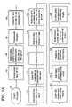
- FIGS. 1A and 1Bare a flow diagram describing the method of treating mitral valve regurgitation in accordance with the present invention.
- FIGS. 2A-Hdepict the stages of the various steps of the method of treating mitral valve regurgitation in accordance with the present invention.
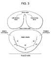
- FIG. 3depicts the plication regions in the method of treating mitral valve regurgitation in accordance with the present invention.
- FIG. 4is a perspective view of a crossing catheter for use in treating mitral valve regurgitation in accordance with the present invention.
- FIG. 5is a cutaway view of a portion of the body of the crossing catheter of FIG. 4 .
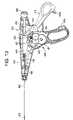
- FIG. 6is an elevational view of a deflecting guide catheter for use in treating mitral valve regurgitation in accordance with the present invention.
- FIGS. 7A and 7Bare an exploded view and a perspective view respectively of the components of a handle for the deflecting guide catheter of FIG. 6 .
- FIG. 8is an elevational view of the body portion of the deflecting guide catheter of FIG. 6 .
- FIGS. 9A and 9Bare cross-sectional views of the body portion of the deflecting guide catheter of FIG. 8 taken through lines A and B respectively.
- FIG. 9Cis a cross-sectional view of an alternative embodiment of the arrangement of the anchor bands in the distal tip of the deflecting guide catheter.
- FIGS. 10A-10Care perspective views of the body portion of other embodiments of a deflecting guide catheter for use in treating mitral valve regurgitation
- FIG. 11is an exploded perspective view of another embodiment of the handle and internal components used in a deflecting guide catheter in accordance with the present invention.
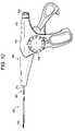
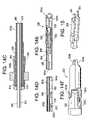
- FIG. 12is an elevational view of a plication device for use in treating mitral valve regurgitation in accordance with the present invention.
- FIG. 13is an elevational view of the plication device of FIG. 12 with a portion removed to expose the internal components.
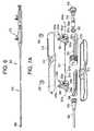
- FIG. 14Ais an elevational view of the plication device of FIGS. 12 and 13 from the shuttle assembly to the distal end.
- FIG. 14Bis a cross sectional view of the portion of the plication device of FIG. 14A taken through line A-A.
- FIG. 14Cis an enlarged view of proximal end section D of the cross-sectional view of the portion of the plication device of FIG. 14B .
- FIG. 14Dis an enlarged view of distal section C of the cross-sectional view of the portion of the plication device of FIG. 14B .
- FIG. 14Eis an enlarged view of the distal tip section B of the cross-sectional view of the portion of the plication device of FIG. 14B .
- FIG. 14Fis an enlarged planar view of the distal tip of the plication device of FIG. 14A .
- FIG. 14Gis a detailed perspective view depicting the coupling of the end-effector control wire to the distal puller wires.
- FIG. 14His a detailed perspective view depicting the coupling of the end-effector control wire to the distal puller wires in an embodiment of the plication device having passive articulation.
- FIG. 15is a perspective view of a retainer for use in a plication device for use in the treatment of mitral valve regurgitation in accordance with the present invention.
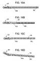
- FIGS. 16A-16Dare elevational views of the distal end of various embodiments of a plication device in accordance with the present invention.
- FIG. 1is a flow diagram depicting a method of providing direct plication annuloplasty to the mitral valve in a heart such as that depicted in FIG. 2A in accordance with the present invention.
- the procedurebegins with a puncture for access to the femoral artery using standard techniques.
- the physician or other practitionerplaces a catheter sheath introducer (CSI) into the femoral access point using standard techniques. Any known CSI may be used in the procedure with the preferable size being approximately 14 french.
- CSIcatheter sheath introducer
- Any known CSImay be used in the procedure with the preferable size being approximately 14 french.
- a crossing catheter, preferably prolapseable or having a curved tip, and a deflecting guide catheterare inserted together in a “stack” formation through the CSI.
- the deflecting guide catheteris inserted through the CSI without a crossing catheter although the use of a crossing catheter is the preferred method.
- the crossing catheteris described herein in greater detail with respect to FIGS. 4 and 5 below and the deflecting guide catheter is described herein in greater detail with respect to FIGS. 6 to 11 .
- the stacked crossing catheter and deflecting guide catheterare advanced through the arterial system of the patient traversing the aorta of the patient in a retrograde manner at step 106 .
- the aortic valve (AV)is crossed with the crossing catheter and the crossing catheter is advanced into the left ventricle (LV) as depicted in FIG. 2B .
- the deflecting guide catheteris advanced over the crossing catheter through the aortic valve and into the left ventricle as depicted in FIG. 2C .
- the deflecting guide catheteris deflected in a somewhat retroflexed manner as it is advanced approximately toward the mitral valve at step 112 as depicted in FIG. 2D and the crossing catheter is withdrawn at step 114 .
- a guidewiremay also be used with the crossing catheter and deflecting guide catheter in a three-element stack inserted in the CSI. If a guidewire is used it is advanced first through the arterial system and over the aortic arch followed by the combined stack of the crossing catheter and the deflecting guide catheter. The guidewire is introduced first through the aortic valve followed by the crossing catheter which is preferably oriented into a position between the papillary muscles although this is not necessary. The procedure then continues as in steps 110 and 112 above with the guidewire removed simultaneously with the crossing catheter at step 114 .
- step 116a region of the deflecting guide catheter is seated toward the mitral valve in the apex of the left ventricle as in FIG. 2E .
- the tip of the deflecting guide catheteris advanced up the posterior wall of the left ventricle to a position under the mitral valve, preferably initially placed in the subvalvular groove in the P 2 region of the as shown in FIG. 3 .
- the term “annulus”is meant to include regions at or near the annulus.
- the position of the tip of the deflecting guide catheteris confirmed by using an imaging method such as fluoroscopy.
- P 2is the likely target region for a first retainer although depending on the geometery of the mitral valve the first retainer may be placed in region P 1 or region P 3 . Additional retainers may need to be placed in the same or other regions.
- a plication device 400 loaded with one or more retainersis inserted into the deflecting guide catheter and advanced to the tip of the deflecting guide catheter.
- a plication device for use in this methodis described in greater detail herein with respect to FIGS. 12 through 14H .
- the rotational orientation of the jaws of the plication deviceis determined using an imaging method and the jaws are placed in the correct orientation.
- the preferable rotational orientation for the jaws of the plication deviceis such that both tips of the jaws once opened would represent a “chord” of the arc defined by the mitral valve annulus when pushed into contact with the annulus.
- the plication deviceis advanced out of the end of the deflecting guide catheter into position under the annulus of the mitral valve as depicted in FIG. 2E .
- the orientation and position of the plication deviceis reconfirmed at step 128 using an imaging method. Again, if fluoroscopy is used as the imaging method, at least one and preferably two views are be used to confirm orientation and placement of the jaws of the plication device.
- An injection of a known contrast agenteither using a separate contrast catheter or through the deflecting guide catheter may be used to help define the line of the annulus as viewed under fluoroscopy.
- a decisionis made by the physician whether or not the jaws of the plication device are properly positioned.
- step 134an attempt is made to reposition the jaws of the plication device.
- step 136the position of the plication device is evaluated again using an imaging method as described previously and in more detail below. If the plication device is positioned correctly then step 132 and onward are performed as discussed below. If the plication device is not positioned properly after at least one attempt at repositioning at step 134 then step 138 results in a determination that the plication device cannot achieve a desired position and the plication device and deflectable guide catheter are withdrawn from the patient at step 150 .
- a diagnostic clamp or plicationis performed at step 132 .
- the jaws of the plication deviceare opened as depicted in FIG. 2F
- the plication deviceis advanced onto the tissue of the annulus of the mitral valve and the jaws are closed as depicted in FIG. 2G .
- the diagnostic plicationis evaluated at steps 140 , 142 and 144 . If the diagnostic plication results in an acceptable change in the mitral valve annulus and/or an acceptable reduction in mitral valve regurgitation then a retainer is applied using the plication device at step 140 and the plication device is released as depicted in FIG. 2H .
- Embodiments of a retainer that may be applied to the tissueare described in greater detail herein with respect to FIG. 15 .
- the diagnostic plicationresults in an unacceptable change to the mitral valve then the procedure is abandoned and both the plication device and the deflectable guide catheter are withdrawn from the patient at step 150 .
- the diagnostic plicationresults in an insufficient or inadequate reduction in mitral valve regurgitation (MR) and/or insufficient or inadequate change in the mitral valve then the diagnostic plication is released and an attempt to reposition the jaws of the plication device is performed at step 134 .
- MRmitral valve regurgitation
- a determination regarding the impact of the plication on the regurgitation of the mitral valveis made using a method of imaging the flow of blood through the valve such as Doppler echocardiograpy.
- steps 146 , 147 and 148various decisions are made regarding the procedure and continuation of the procedure.
- the procedurebranches to step 150 with the retrieval of the plication device and the deflecting guide catheter.
- step 147the plication device currently in use is withdrawn if it is a single retainer device and an additional plication device is inserted and the procedure continues from step 122 . If the plication device is a multi-retainer device then the procedure continues from step 124 without withdrawal of the plication device. If the determination regarding the impact of the plication on mitral valve regurgitation results in a finding of an adverse result at step 148 then the procedure will likely be abandoned and both the plication device and deflecting guide catheter are removed from the patient at step 150 . After removal of the plication device and the deflecting guide catheter, the catheter sheath introducer is removed and the access site is closed at step 152 using known methods.
- Fluoroscopyis one real-time imaging modality that is useful, preferably, where images are taken in at least two planes. Radiopaque markers placed on the distal end of the plication device and/or deflecting guide will aid in determining proper placement.
- a three-dimensional profile of the plication devicecan be created using x-ray images acquired in at least two planar projections in real-time. Alternatively, rotational angiographic imaging may be used. Additionally, registering pre-acquired CT or MRI image data with the fluoroscopic image will provide additional anatomic data to the physician to aid proper placement of the plication device and retainer or retainer. Similarly, a three-dimensional real-time ultrasound image acquired in real-time may be registered with the fluoroscopic image.
- ICEintracardiac echocardiography
- the ICE imagemay be produced by an ICE catheter placed inside one of the chambers of the heart such as the right ventricle, left ventricle, left atrium or the right atrium.
- the ICE cathetercould be placed inside on of the great vessels of the heart of the patient.
- the ICE cathetermay also be placed on the epicardial or pericardial sack surfaces of the heart via a minimally invasive approach such as a sub-xiphoid approach.
- the images of the mitral valveshould be taken synchronized to the cardiac cycle.
- Various imaging modalitiesare also useful in determining whether the plication achieves the desired impact on the function of the mitral valve in real-time or near real-time prior to applying the retainer to the plication.
- Real-timemeans that the latency period is acceptable to perform the procedure and is preferably no more than 500 milliseconds.
- Color Doppler ultrasound imagingmay be used for such a purpose with or without an ultrasound contrast agent being administered to the patient.
- x-ray fluoroscopycould be used in determining the impact of a plication on mitral valve regurgitation by using an x-ray contrast bolus injection into one of the chambers of the heart, preferably the left ventricle.
- Bi-planar angiographic imaging or intra-chamber optical imagingmay also be used. If intra-chamber optical imaging is used it is preferable that the deflecting guide catheter further comprise an optical imaging system particularly one that operates in infrared wavelengths.
- Determining a location for the first tissue plicationmay be based on an optimization plan generated using a three-dimensional functional numerical simulation based on imaging data generated by one or more of the aforementioned imaging method. For example, by analyzing the distribution of annular tissue relative to the location of the primary regurgitant flow through the valve, a primary target for initial plication therapy may be determined. It may be desirable to place the plication at the location of greatest distortion of the annulus due to the pathology of the patient's heart.
- the generation of the optimization planmay be performed prior to step of inserting the crossing catheter.
- the generation of the optimization planmay be performed after the step of applying a retainer to the first tissue plication in order to determine the preferred location for subsequent plication or plications.
- the plicationscould be made on the atrial surface if a transseptal approach is used. This can be accomplished by accessing the right atrium using SVC or IVC venous approaches. Then access the left atrium is accomplished using a standard transseptal puncture/access kit such as a Brockenbrough transseptal needle kit. The deflecting guide catheter would then be introduced through the puncture and deflected such that the tip pointed towards the annulus of the mitral valve. The subsequent steps and devices for a plication annuloplasty procedure would then be the substantially the same as set forth above except that the approach is from the atrial side of the mitral valve rather than the underside.
- FIG. 4is a perspective view of a crossing catheter 200 for use in the procedure described in the present application.
- Crossing catheter 200is comprised of a body portion 210 having a proximal end 210 a and a distal end 210 b .
- Connected to proximal end 210 aare a female luer lock 216 and a Tuohy-Borst hemostasis valve 214 .
- Pigtail 218is approximately 2.0 centimeters or less in diameter.
- pigtail 218is attached to body portion 210 at a splice location that is approximately 4 centimeters from the distal end of the device.
- Pigtail 218is attached to body portion 210 using heat bonding as the body portion 210 and pigtail 218 re made from the same or similar material.
- Pigtail 218is comprised of a polymer, preferably, Pebax® polyether block amide having a durometer of approximately 55 D if comprised of one layer or two layers having durometers of approximately 40 D in the outer layer and 55 D in the inner layer.
- Body portion 210may be comprised of one layer having a durometer between 55 D and 72 D or may have two layers. If two layers are used the preferred durometers are 70 D for the outside and 63 D for the inside.
- the total length of the body portion and pigtail togetheris approximately 149 centimeters and should extend beyond the deflecting guide catheter when fully inserted into the deflecting guide catheter thus the length of the crossing catheter may vary depending on the length of the deflecting guide catheter used.
- the location at which the pigtail may be attached to the body portionmay also vary from 3 centimeters to approximately 44.5 centimeters from the distal tip of the crossing catheter 200 .
- the crossing cathetermay also be comprised of one material from the body portion through the pigtail. In such a case the use of an outer material with a durometer of 55 D and an inner material with a durometer of 40 D is preferred.
- a flat wire braid 212 of flat wires of approximately 0.001′′ by 0.003′′may be embedded in the polymer comprising the proximal portion of body portion 210 in order to provide extra stiffness and torqueability.
- An inner layer 211 of PTFEprovides a lubricious inner coating and a separation between the polymer and the inner lumen.
- the stiffness of the pigtail portion of the crossing catheteris chosen so that a standard guidewire such as the Cordis Emerald 0.035′′ guidewire will open up the pigtail yet will return to the pigtail shape when retracted.
- a standard guidewiresuch as the Cordis Emerald 0.035′′ guidewire will open up the pigtail yet will return to the pigtail shape when retracted.
- Such a guidewireis placed in the guidewire lumen defined by the inner layer 211 of the crossing catheter and should extend through the entire length of the crossing catheter.
- Crossing catheter 200may be used with or without a guidewire as described above and is preferably used in conjunction with the deflecting guide catheter depicted in FIGS. 6 through 10 A-C.
- Deflecting guide catheter 300is comprised of a handle 310 and a body portion 350 .
- FIG. 7Ais an exploded view of an embodiment of the handle 310 depicting the internal components of the handle and
- FIG. 7Bis a perspective view of the internal components of handle 310 as assembled.
- Handle 310is comprised of upper handle shell 312 and lower handle shell 314 which are made of a durable moldable polymeric material such as polycarbonate or other similar material and are designed to mate with one another in a snap fit arrangement.
- a hemostasis valve 316which is adapted to fit onto the proximal handle tip 318 .
- Hemostasis valve 316may be of any known design for such a valve such as a tuohy-borst type valve.
- Proximal actuator assembly 324is comprised of a thumb actuator 324 a that is adapted to be inserted through slot 313 in the upper handle shell 312 .
- a two-piece construction with a thumb cap 325may be used to facilitate assembly if slot 313 is narrow.
- the thumb actuator 324 a and optional thumb 325 capare used to cause forward motion in the proximal direction of puller wire 327 a .
- Such motionis retained as the prong or prongs 324 e biased by spring 324 d around pivot point axel pin 324 c engages the teeth 322 a in proximal rack 322 .
- Such proximal motion of the proximal actuator assembly 324 and the associated puller wire 327 acauses the deflection of the distal end of the deflecting guide catheter 300 .
- the user pushersrelease trigger 324 b which counters the bias of spring 324 d thereby releasing prong or prongs 324 e from engagement with the teeth 322 a of the proximal rack 322 .
- Proximal hypotube 331 aprovides a passageway for puller wire 327 a and prevents kinking of the wire.
- Distal hypotube 331 bis designed to telescope inside hypotube 331 a .
- crimp tube 334 aAt the end of puller wire 327 a are fixedly attached crimp tube 334 a and a floating crimp tube stop 334 b that prevents the crimp tube from being embedded in the proximal end of the actuator assembly.
- the usermay then move the actuator assembly distally thereby changing the deflection of the distal end of the deflecting guide catheter. Movement of the actuator assembly may be made by the physician using something other than his or her thumb and the terms “thumb actuator” and “thumb cap” are not meant to be limiting.
- Handle 310further comprises a distal actuator assembly 328 having a similar thumb actuator 328 a , release trigger 324 b , axel pin 324 c , spring 328 d and prong 328 e .
- Optional thumb cap 329is affixed over thumb actuator 328 a .
- the distal actuator assembly 328is connected to a second pullerwire 327 b (shown in FIG. 11 ) that enables the user to cause deflection of the distal end of the deflecting guide catheter.
- first and second puller wiresare attached (through known methods and means such as welding, brazing or adhesives) to anchor bands 385 a and 385 b that are embedded in the distal region 360 of the body portion 350 of the deflecting guide.
- the puller wires and their respective anchor band connection pointsmay also be arranged so that they are not next to one another (in an axial manner) but so that each provides motion of the distal end in another plane or in the other direction within the same plane.
- the second puller wire and actuatorare not necessary if it is only necessary to provide one type of movement in the deflecting guide catheter.
- additional thumb actuator assemblies coupled to puller wires and anchor bandsmay be added in a similar manner to the catheter.
- the second distal actuator assemblyhas the same components as functions in the same manner as the proximal actuator assembly.
- the primary differenceis that the distal actuator assembly 328 requires a passageway for passage of the first puller wire 327 a through the distal assembly which passage is aided by hypotube 331 b .
- the second puller wire 327 bends at the distal end with a similar crimp tube 335 a and crimp tube stop 335 b .
- Nose cone 330provides a transition between the handle shell 312 / 314 and the proximal region 390 of the body portion 350 .
- Actuator assemblies 324 and 328 and racks 322 and 326are comprised of a polymeric material such as polycarbonate. Such assemblies could be made of machined or molded metal, such as aluminum, although that would result in a higher cost and weight device.
- Racks 322 and 326 with teeth 322 a and 326 amay be separate components or may preferably be molded into the lower handle shell 314 as depicted in the alternative embodiment shown in FIG. 11 .
- Handle insert 338is used as a divider between the two racks 322 and 326 and provides a support for proximal hypotube 331 a .
- Puller wires 327 a and 327 bare preferably high tensile strength 304 stainless steel (e.g. tensile strength greater than 300 ksi) but may also be made of other high strength materials such as MP35N, other stainless steel, or woven fibers such as Kevlar or Vectran.
- Puller wires 327 a and 327 bare preferably a single, solid core high tensile strength 304 stainless steel wire (e.g. tensile strength greater than 300 ksi) of approximately 0.008′′ in diameter but may also be made of other high strength materials such as MP35N, other stainless steel, or woven fibers such as Kevlar or Vectran.
- an anchor band 385 a or 385 bthat is embedded in the wall of the catheter body at the point of anchoring. Changing the location of the anchor band along the axial length of the catheter body will change the deflection profile of the deflectable guide catheter.
- Body portion 350 of deflecting guide catheter 300is depicted in FIG. 8 and FIGS. 9A and 9B .
- Body portionis separated into four regions: distal region 360 , intermediate distal region 370 , main intermediate region 380 and proximal region 390 .
- Distal region 360 at the distal endis approximately 3.5 centimeters in length and is made of a polymeric material such as Pebax with a durometer of between 25 D and 40 D and preferably 35 D.
- a radiopaque materialsuch as bismuth subcarbonate is added to the material in distal region 360 to enable the distal region 360 of the deflecting guide catheter 300 appear in fluoroscopy and other imaging procedures.
- the wall thickness in the distal region 360is between approximately 0.012 and 0.014 inches.
- the anchor band 385 a for the first puller wireis embedded near the distal end of distal region 360 and the anchor band 385 b for the second puller wire is embedded near the proximal end of distal region 360 or at the distal end of region 370 .
- This arrangementmay also be reversed so that the anchor band for the first puller wire is embedded near the proximal end of the distal region and the anchor band for the second puller wire is embedded near the distal end of the distal region. It is also possible to place the anchor bands next to one another rather than longitudinally separated as depicted in the embodiment shown.
- the anchor bandsare preferably tubular metal bands preferably placed between the lubricious liner 365 and the braid 375 although it could be placed above the braid in an alternative embodiment.
- FIG. 9Cdepicts an alternative arrangement of the proximal anchor band 385 a in which a notch or lumen is placed in the anchor band to allow the passage of the second puller wire 327 b in braid reinforced puller wire lumen 395 b through at least a radial portion of the anchor band.
- Puller wire 327 ais attached to anchor band 385 a . This arrangement enables the catheter to have a more symmetrical and smaller profile at this point.
- the internal diameter of distal region 360 as well as the entire body portionis defined by a lubricious liner 365 preferably PTFE that has an interior diameter of approximately 0.127 inches and is approximately 0.002 inches thick.
- the outer diameter of distal region 360is approximately 0.172 inches between the anchor bands and approximately 0.176 inches at the location of the distal band.
- a braid 375 of wires having a diameter between 0.0025 and 0.003 inches in either a 1 over 1, 1 over 2 under 2 or 2 over 2 patternis embedded in the polymeric wall of the catheter from the proximal region 390 to the distal region 360 .
- atraumatic tip 362comprised of approximately 33.5% 25 D Pebax, approximately 6.4% 55 D Pebax and approximately 60% bismuth subcarbonate and having a slight taper toward its distal end.
- the atraumatic tipis optional although preferred in order to avoid tissue damage during insertion into the vessels of the patient.
- the distal region 360is comprised of a polymeric material having a higher durometer than both the atraumtic tip 362 and the intermediate distal region 370 .
- This stiffer distal region between anchor bands 382 a and 385 bwill enable the deflection profile of the deflecting guide catheter to be altered in such a way as to allow the deflected shape of the catheter to better match the shape of the target anatomy for the device.
- an alternative embodimentadds an additional region of material between the distal and intermediate distal regions, which is of a durometer different from that of both adjacent regions. This is also done to alter the deflected shape of the catheter in a favorable manner and create a region which either deflects much more or much less (depending if the durometer is lower or higher than adjacent regions) than the adjacent regions.
- Intermediate distal region 370is comprised of the same type of polymeric material but has a higher durometer of between 35 D and 55 D to provide a stiffer region. Intermediate distal region 370 is between approximately 2.8 and 4.0 centimeters in length and contains the same lubricious liner 365 and wire braid 375 as the distal region. The wall thickness in the intermediate distal region is similarly between 0.012 and 0.014 inches and the outer diameter is approximately 0.172 inches.
- Main intermediate region 380has a slightly smaller outer diameter at 0.166 inches but has the same lubricious liner and braid as the other regions. The main difference in this region is the higher durometer of between 55 D and 63 D for the polymeric material used in order to provide increasing stiffness.
- the main intermediate regionis approximately 20 to 30 centimeters in length, preferably 20 centimeters.
- Proximal region 390has a similar composition in that the outer diameter is the same as the immediately prior region.
- the durometer in this regionis increased to approximately 72 D providing even greater stiffness and the length of this region is approximately 73 to 90 centimeters, preferably 88 centimeters.
- the lubricious layer 365 and braid 375are the same.
- first and second anchor bands 385 a / 385 brun two braid reinforced tubes 395 a / 395 b of approximately 0.0088 inches in internal diameter which house the first and second puller wires respectively.
- the braidmay be changed to a different size or cross section (such as elliptical) wire and braid type.
- the polymeric material of the outer bodymay be varied as depicted in FIGS. 10A-10C . In FIG. 10A materials having two different durometers are used in an alternating fashion.
- Material Ais used in two circumferential portions opposite one another while material B is used in two other opposing circumferential portions.
- the durometer of material Amay be greater than the durometer of material B or vice versa depending on the deflection characteristics desired.
- Use of two different durometer materials in such a wayprovides the benefit of balancing the ability or ease of the catheters to deflect in a particular direction with the requirement for lateral stiffness.
- FIG. 10Btwo circumferential portions of material A and material B are used to provide a certain desired deflection characteristic.
- FIG. 10Cthe use of two different durometer materials is used in conjunction with placement of the puller wires 327 a and 327 b at different places along the circumference of the body portion. In the configuration in FIG.
- the distal end of the deflecting guide catheterwould deflect in two different planes substantially perpendicular to one another.
- the planes of deflectionare primarily determined by the relative placement of the puller wire lumens.
- the deflecting guide cathetermay further comprise a magnetic based location sensor such as those manufactured by Biosense Webster for sensing the location and orientation (six degrees of freedom) of the distal end of the deflecting guide catheter and for providing location information that may be registered with other preaquired or real-time images or otherwise used to depict the location of the distal end of the deflecting guide catheter on a real-time display map of the heart.
- a magnetic based location sensorsuch as those manufactured by Biosense Webster for sensing the location and orientation (six degrees of freedom) of the distal end of the deflecting guide catheter and for providing location information that may be registered with other preaquired or real-time images or otherwise used to depict the location of the distal end of the deflecting guide catheter on a real-time display map of the heart.
- Systemssuch as the Carto® system produced by Biosense Webster would be useful for this purpose.
- FIG. 12is an elevational view of a plication device 400 for use in the method of treating mitral valve regurgitation in accordance with the present invention.
- Plication device 400is comprised of a handle assembly 410 and a distal assembly 450 having an elongate shaft 452 at the distal end of which are attached a plication assembly with an end effector 520 .
- FIG. 13is an elevational view of the internal components of the handle assembly 410 .
- Handle assembly 410is comprised of two polycarbonate shell portions right handle shell 412 and left handle shell 414 that are adapted to house the internal components of the handle assembly.
- Internal to handle assembly 410reside crank assembly 420 for advancing a retainer stored in the distal portion of the elongate shaft 452 .
- the firing assembly 420is comprised of counter gear 421 , drive gear assembly 422 , idle gear 423 , and crown gear 424 . Firing assembly 420 is coupled to the firing knob 430 , shown in FIG. 12 , which is rotatably coupled to left handle shell 414 . While not shown, a second firing knob can be disposed on the opposed side of the handle assembly 410 to allow a user to selectively rotate either knob. Either firing knob further comprises a anti-backup leaf spring (not shown) that prevents the knob from turning in the reverse direction and a trigger lockout spring (not shown) that prevents the knob from turning until the trigger is fully closed or engaged. Continuing to refer to refer to FIG.
- the gears 421 , 422 , 423 and 424 of firing assembly 420are configured to rotate in response to rotation of the firing knob 430 .
- the gearscommunicate with one another to cause corresponding rotation of pinion assembly 437 and drive shaft 436 .
- Drive shaft 436is mated to a proximal end of firing control wire 490 .
- End cap 460has a plurality of ridges dispersed around it circumference to aid the grip of the user.
- the trigger 416is pivotally mounted within the handle assembly 410 by a pivot pin 417 , and includes a distal portion having a thumb grip formed therein and a proximal extension arm 418 .
- the trigger 416also includes a latch 419 a that is adapted to be received in the latch receiver 419 b in the handle assembly to lock the trigger into a closed position.
- the extension arm 418is coupled to a shuttle assembly 440 that moves between proximal and distal positions within the housing assembly 410 .
- the shuttle assembly 440can have various configurations and it can include various features, such as an overload mechanism. The particular configuration of the shuttle assembly 440 is described in more detail in U.S. Patent Publication No. 2005/0277954 herein incorporated by reference.
- FIGS. 14A and 14BSome of the internal parts of the shuttle assembly 440 including spring pin 446 , force limiting spring 442 , spring caps 444 a and 444 b are shown in FIGS. 14A and 14B .
- the shuttle assembly 440is coupled to a proximal portion of end-effector control wire 510 , which extends through the elongate shaft 452 .
- the distal end of the end effector control wire 510mates (preferably by welding) to wire connector 542 , which is shown in FIG. 14D
- the wire connector 542is positioned as shown in FIG. 14G proximal to the end effector 520 , i.e., the clevis 522 and jaws 524 a and 524 b .
- Wire connector 542is also welded to two parallel pull wires 544 a and 544 b that run from wire connector 542 through nut 550 and terminate in holes at the proximal end of jaws 524 a and 524 b respectively.
- wire connector 542splits the force of end effector control wire 510 into two forces for controlling the opening and closing of the jaws.
- Other arrangementsare possible if, for example, it would be desired to have one fixed jaw and one movable jaw rather than two movable jaws. It is also possible to have some passive articulation of the distal jaws 524 a and 524 b by having the pull wires 544 a and 544 b pass through wire connector 542 as depicted in FIG.
- Distal jaws 524 a and 524 brotate around pivot point rivots 523 a and 523 b respectively.
- the firing control wire 490extends through the elongate shaft 452 and through a bore formed in the wire connector 542 and is threadably mated to a threaded bore in nut 550 .
- the distal end of the firing control wire 490extends into a retainer pusher 554 set in a retainer pusher sleeve 556 , both of which are shown in FIG. 14E and which is described in more detail in US. Publication No. 2005/0277954.
- rotation of the firing knob 430is effective to rotate the firing control wire 490 .
- the firing control wire 490is threadably mated to the nut 550 , which is fixed between the proximal and distal portions of the elongate shaft 452 , the threaded bore in nut 550 will cause the firing control wire 490 to move distally through the elongate shaft 452 , thereby advancing the retainer pusher 554 in a distal direction.
- the retainer pusher 554is positioned proximal to one or more retainers 500 stored within a garage 532 in the distal portion of the elongate shaft 452 , and thus distal movement of the pusher 554 will advance the retainers 550 through the shaft 452 to position the distal most retainer within the jaws 524 a and 524 b of the end effector 520 .
- a person skilled in the artwill appreciate that a variety of other techniques can be used to advance a plurality of retainers through the elongate shaft and to position a retainer within the jaws.
- the coil connector 512which is made of a metal, preferably brass, and is used as a means for connecting the proximal portion 452 a of elongate shaft 452 to the handle assembly.
- Dual lumen inner sheath 560has lumens for end-effector control wire 510 and firing control wire 490 .
- Filler tube connector 562is used to connect the coil connector 512 to the elongate shaft 452 and is glued to coil connector 512 and elongate shaft 452 using an adhesive glue such as cyanoacrylate.
- Elongate shaft 452is broken into proximal shaft section 452 a and distal shaft section 452 b .
- Proximal shaft section 452 ais preferably nitinol and has a dovetail laser pattern.
- Distal shaft section 452 bis preferably stainless steel and has a similar dovetail pattern cut through the wall of the shaft. Other patterns could also be used such as a helical cut as shown in FIG. 16A .
- FIG. 16Bdepicts another variation of the plication device where the proximal shaft section is similar to that above but the nut is placed significantly more distally and the stainless steel distal shaft section with a dovetail pattern is replaced with a helical cut creating a ribbon coil.
- FIG. 16Cdepicts the placement of the nut and the dovetail patterns of the proximal and distal shaft portions discussed with respect to FIGS. 14A-F above.
- FIG. 16Ddepicts the passively articulating jaws of the alternative embodiment discussed above.
- Retainer 500is comprised of stainless steel or other biocompatible material such as MP35N, platinum, nitinol and cobalt chromium or alloys thereof.
- the helical retainermay also be made of a or polymeric material such as one made of poly lactic acid
- the retaineris comprised of a metal alloy with the preferred embodiment containing at least a trace of an element having an atomic number greater than 53 such as platinum to enhance visibility of the retainer under fluoroscopy. Additionally, a sufficient wall thickness should be chosen to ensure visibility under fluoro.
- the shape of the tip of the distal jaws of the plication devicealso have an alignment feature when viewed under fluoro that allows the viewer to determine which of 2 orientations (0/180 or 90/270) the jaws are in. In a 0/180 orientation the tip of the jaws form a circle as depicted in FIG. 14F . In a 90/270 orientation the tip of the jaws form a minus as depicted in FIG. 14B .
- the retainer 500is preferably “C” shaped with elongated legs which may vary in length depending on the depth of tissue to be penetrated and the number of retainers that are desired to be housed within the garage of the plication device.
- the tips 501are designed to be folded by the distal tips of the jaws of the end effector during the process of advancement to prevent the retainer from backing out or being pulled out of the plicated tissue.
- the retainercould be coated with one or more pharmacologically active agents such as heparin for the purpose of reducing thrombotic potential.
- the plication devicemay further comprise a magnetic based location sensor such as those manufactured by Biosense Webster for sensing the location and orientation (six degrees of freedom, x, y, z, roll (Xrot), pitch (Yrot) and yaw (Zrot)) of the distal end of the deflecting guide catheter and for providing location information that may be registered with other preaquired or real-time images or otherwise used to depict the location of the distal end of the deflecting guide catheter on a real-time display map of the heart.
- Systemssuch as the Carto® system produced by Biosense Webster would be useful for this purpose.
- the incorporation of the magnetic based location sensor near the distal tip of the plication deviceenables precise orientation of the jaws in order to facilitate placement of the jaws and plication of the tissue.
- the magnetic location sensorswould be placed proximal the distal end of the jaws of the plication device due to shielding if such sensors were placed in the jaws themselves.
- Location informationis then transmitted through electrical conductors to circuitry in the handle of the plication device which is electrically connected to a Carto® mapping system.
- the Carto® mapping systemwill then use the location information from the magnetic location sensors in order to extrapolate the location and layout of the distal end of the plication device.
- a sensorshould also be placed in the handle of the plication device that would provide a signal to the Carto® system indicative of the open/closed position of the jaws. With this information the Carto® system will be able to display a real-time image of the heart and the location of the distal end of the plication device within the left ventricle, etc.
- the devices disclosed hereincan also be designed to be disposed of after a single use, or they can be designed to be used multiple times. In either case, however, the device can be reconditioned for reuse after at least one use. Reconditioning can include any combination of the steps of disassembly of the device, followed by cleaning or replacement of particular pieces, and subsequent reassembly.
- the devicecan be disassembled, and any number of the particular pieces or parts of the device can be selectively replaced or removed in any combination.
- the devicecan be reassembled for subsequent use either at a reconditioning facility, or by a surgical team immediately prior to a surgical procedure.
- reconditioning of a devicecan utilize a variety of techniques for disassembly, cleaning and/or replacement, and reassembly. Use of such techniques, and the resulting reconditioned device, are all within the scope of the present application.
Landscapes
- Health & Medical Sciences (AREA)
- Life Sciences & Earth Sciences (AREA)
- Engineering & Computer Science (AREA)
- Animal Behavior & Ethology (AREA)
- Veterinary Medicine (AREA)
- Public Health (AREA)
- General Health & Medical Sciences (AREA)
- Biomedical Technology (AREA)
- Heart & Thoracic Surgery (AREA)
- Pulmonology (AREA)
- Hematology (AREA)
- Anesthesiology (AREA)
- Biophysics (AREA)
- Surgery (AREA)
- Mechanical Engineering (AREA)
- Nuclear Medicine, Radiotherapy & Molecular Imaging (AREA)
- Medical Informatics (AREA)
- Molecular Biology (AREA)
- Surgical Instruments (AREA)
- Prostheses (AREA)
Abstract
Description
Claims (47)
Priority Applications (14)
| Application Number | Priority Date | Filing Date | Title |
|---|---|---|---|
| US12/341,493US8197464B2 (en) | 2007-10-19 | 2008-12-22 | Deflecting guide catheter for use in a minimally invasive medical procedure for the treatment of mitral valve regurgitation |
| AU2009330182AAU2009330182B2 (en) | 2008-12-22 | 2009-12-21 | Deflecting guide catheter for mitral valve treatment |
| EP13167307.1AEP2626012B1 (en) | 2008-12-22 | 2009-12-21 | Deflecting guide catheter for mitral valve treatment |
| CN200980152853.4ACN102264308B (en) | 2008-12-22 | 2009-12-21 | For the deflectable catheter of Bicuspid valve treatment |
| EP13167329.5AEP2656795A1 (en) | 2008-12-22 | 2009-12-21 | Deflecting guide catheter for mitral valve treatment |
| EP13167310.5AEP2656794A1 (en) | 2008-12-22 | 2009-12-21 | Deflecting guide catheter for mitral valve treatment |
| PCT/US2009/068911WO2010075245A2 (en) | 2008-12-22 | 2009-12-21 | Deflecting guide catheter for use in a minimally invasive medical procedure for the treatment of mitral valve regurgitation |
| JP2011542527AJP5631892B2 (en) | 2008-12-22 | 2009-12-21 | A deflection guide catheter used in minimally invasive medical procedures for mitral regurgitation therapy |
| EP13167331.1AEP2656796A1 (en) | 2008-12-22 | 2009-12-21 | Deflecting guide catheter for mitral valve treatment |
| EP09803959AEP2361041A2 (en) | 2008-12-22 | 2009-12-21 | Deflecting guide catheter for mitral valve treatment |
| CA2748036ACA2748036C (en) | 2008-12-22 | 2009-12-21 | Deflecting guide catheter for use in a minimally invasive medical procedure for the treatment of mitral valve regurgitation |
| EP15184351.3AEP3017771B1 (en) | 2008-12-22 | 2009-12-21 | Deflecting guide catheter for use in a minimally invasive medical procedure for the treatment of mitral valve regurgitation |
| EP13167309.7AEP2626013B8 (en) | 2008-12-22 | 2009-12-21 | Deflecting guide catheter for mitral valve treatment |
| AU2015203584AAU2015203584B2 (en) | 2008-12-22 | 2015-06-26 | Deflecting guide catheter for use in a minimally invasive medical procedure for the treatment of mitral valve regurgitation |
Applications Claiming Priority (3)
| Application Number | Priority Date | Filing Date | Title |
|---|---|---|---|
| US98130307P | 2007-10-19 | 2007-10-19 | |
| US12/249,388US8226709B2 (en) | 2007-10-19 | 2008-10-10 | Method and system for plicating tissue in a minimally invasive medical procedure for the treatment of mitral valve regurgitation |
| US12/341,493US8197464B2 (en) | 2007-10-19 | 2008-12-22 | Deflecting guide catheter for use in a minimally invasive medical procedure for the treatment of mitral valve regurgitation |
Related Parent Applications (1)
| Application Number | Title | Priority Date | Filing Date |
|---|---|---|---|
| US12/249,388Continuation-In-PartUS8226709B2 (en) | 2007-10-19 | 2008-10-10 | Method and system for plicating tissue in a minimally invasive medical procedure for the treatment of mitral valve regurgitation |
Publications (2)
| Publication Number | Publication Date |
|---|---|
| US20100076408A1 US20100076408A1 (en) | 2010-03-25 |
| US8197464B2true US8197464B2 (en) | 2012-06-12 |
Family
ID=42046456
Family Applications (1)
| Application Number | Title | Priority Date | Filing Date |
|---|---|---|---|
| US12/341,493Expired - Fee RelatedUS8197464B2 (en) | 2007-10-19 | 2008-12-22 | Deflecting guide catheter for use in a minimally invasive medical procedure for the treatment of mitral valve regurgitation |
Country Status (7)
| Country | Link |
|---|---|
| US (1) | US8197464B2 (en) |
| EP (7) | EP2656795A1 (en) |
| JP (1) | JP5631892B2 (en) |
| CN (1) | CN102264308B (en) |
| AU (1) | AU2009330182B2 (en) |
| CA (1) | CA2748036C (en) |
| WO (1) | WO2010075245A2 (en) |
Cited By (29)
| Publication number | Priority date | Publication date | Assignee | Title |
|---|---|---|---|---|
| US9445899B2 (en) | 2012-08-22 | 2016-09-20 | Joseph M. Arcidi | Method and apparatus for mitral valve annuloplasty |
| US9898937B2 (en) | 2012-09-28 | 2018-02-20 | Applied Medical Resources Corporation | Surgical training model for laparoscopic procedures |
| US9922579B2 (en) | 2013-06-18 | 2018-03-20 | Applied Medical Resources Corporation | Gallbladder model |
| US9940849B2 (en) | 2013-03-01 | 2018-04-10 | Applied Medical Resources Corporation | Advanced surgical simulation constructions and methods |
| US9959786B2 (en) | 2012-09-27 | 2018-05-01 | Applied Medical Resources Corporation | Surgical training model for laparoscopic procedures |
| EP3363355A1 (en) | 2017-02-15 | 2018-08-22 | Biosense Webster (Israel) Ltd. | Electrophysiologic device construction |
| US10081727B2 (en) | 2015-05-14 | 2018-09-25 | Applied Medical Resources Corporation | Synthetic tissue structures for electrosurgical training and simulation |
| US10121391B2 (en) | 2012-09-27 | 2018-11-06 | Applied Medical Resources Corporation | Surgical training model for laparoscopic procedures |
| US10140889B2 (en) | 2013-05-15 | 2018-11-27 | Applied Medical Resources Corporation | Hernia model |
| US10198966B2 (en) | 2013-07-24 | 2019-02-05 | Applied Medical Resources Corporation | Advanced first entry model for surgical simulation |
| US10198965B2 (en) | 2012-08-03 | 2019-02-05 | Applied Medical Resources Corporation | Simulated stapling and energy based ligation for surgical training |
| US10223936B2 (en) | 2015-06-09 | 2019-03-05 | Applied Medical Resources Corporation | Hysterectomy model |
| US10332425B2 (en) | 2015-07-16 | 2019-06-25 | Applied Medical Resources Corporation | Simulated dissectible tissue |
| US10354556B2 (en) | 2015-02-19 | 2019-07-16 | Applied Medical Resources Corporation | Simulated tissue structures and methods |
| US10395559B2 (en) | 2012-09-28 | 2019-08-27 | Applied Medical Resources Corporation | Surgical training model for transluminal laparoscopic procedures |
| US10490105B2 (en) | 2015-07-22 | 2019-11-26 | Applied Medical Resources Corporation | Appendectomy model |
| US10535281B2 (en) | 2012-09-26 | 2020-01-14 | Applied Medical Resources Corporation | Surgical training model for laparoscopic procedures |
| US10657845B2 (en) | 2013-07-24 | 2020-05-19 | Applied Medical Resources Corporation | First entry model |
| US10679520B2 (en) | 2012-09-27 | 2020-06-09 | Applied Medical Resources Corporation | Surgical training model for laparoscopic procedures |
| US10706743B2 (en) | 2015-11-20 | 2020-07-07 | Applied Medical Resources Corporation | Simulated dissectible tissue |
| US10720084B2 (en) | 2015-10-02 | 2020-07-21 | Applied Medical Resources Corporation | Hysterectomy model |
| US10796606B2 (en) | 2014-03-26 | 2020-10-06 | Applied Medical Resources Corporation | Simulated dissectible tissue |
| US10818201B2 (en) | 2014-11-13 | 2020-10-27 | Applied Medical Resources Corporation | Simulated tissue models and methods |
| US10847057B2 (en) | 2017-02-23 | 2020-11-24 | Applied Medical Resources Corporation | Synthetic tissue structures for electrosurgical training and simulation |
| US10854112B2 (en) | 2010-10-01 | 2020-12-01 | Applied Medical Resources Corporation | Portable laparoscopic trainer |
| US11030922B2 (en) | 2017-02-14 | 2021-06-08 | Applied Medical Resources Corporation | Laparoscopic training system |
| US11120708B2 (en) | 2016-06-27 | 2021-09-14 | Applied Medical Resources Corporation | Simulated abdominal wall |
| US11158212B2 (en) | 2011-10-21 | 2021-10-26 | Applied Medical Resources Corporation | Simulated tissue structure for surgical training |
| US11403968B2 (en) | 2011-12-20 | 2022-08-02 | Applied Medical Resources Corporation | Advanced surgical simulation |
Families Citing this family (58)
| Publication number | Priority date | Publication date | Assignee | Title |
|---|---|---|---|---|
| WO2003105670A2 (en) | 2002-01-10 | 2003-12-24 | Guided Delivery Systems, Inc. | Devices and methods for heart valve repair |
| US20070055206A1 (en)* | 2005-08-10 | 2007-03-08 | Guided Delivery Systems, Inc. | Methods and devices for deployment of tissue anchors |
| US8388680B2 (en)* | 2006-10-18 | 2013-03-05 | Guided Delivery Systems, Inc. | Methods and devices for catheter advancement and delivery of substances therethrough |
| US8096985B2 (en) | 2008-05-07 | 2012-01-17 | Guided Delivery Systems Inc. | Deflectable guide |
| BRPI0920406A2 (en)* | 2008-10-10 | 2019-09-24 | Guided Delivery Systems Inc | termination devices and related methods. |
| JP2012505049A (en)* | 2008-10-10 | 2012-03-01 | ガイデッド デリバリー システムズ, インコーポレイテッド | Tether tensioning device and related methods |
| EP2389218A4 (en)* | 2009-01-20 | 2012-06-13 | Guided Delivery Systems Inc | Diagnostic catheters, guide catheters, visualization devices and chord manipulation devices, and related kits and methods |
| WO2010085456A1 (en) | 2009-01-20 | 2010-07-29 | Guided Delivery Systems Inc. | Anchor deployment devices and related methods |
| EP3659490B1 (en) | 2010-08-20 | 2025-10-01 | Veran Medical Technologies, Inc. | Apparatus and method for four dimensional soft tissue navigation |
| CA2822381C (en) | 2010-12-23 | 2019-04-02 | Foundry Newco Xii, Inc. | System for mitral valve repair and replacement |
| JP5872692B2 (en) | 2011-06-21 | 2016-03-01 | トゥエルヴ, インコーポレイテッド | Artificial therapy device |
| US9039757B2 (en) | 2011-10-19 | 2015-05-26 | Twelve, Inc. | Prosthetic heart valve devices, prosthetic mitral valves and associated systems and methods |
| EA201400478A1 (en) | 2011-10-19 | 2014-10-30 | Твелв, Инк. | DEVICES, SYSTEMS AND METHODS OF PROTESIZING THE HEART VALVE |
| US9655722B2 (en) | 2011-10-19 | 2017-05-23 | Twelve, Inc. | Prosthetic heart valve devices, prosthetic mitral valves and associated systems and methods |
| US9763780B2 (en) | 2011-10-19 | 2017-09-19 | Twelve, Inc. | Devices, systems and methods for heart valve replacement |
| JP6133309B2 (en) | 2011-10-19 | 2017-05-24 | トゥエルヴ, インコーポレイテッド | Prosthetic heart valve device |
| US11202704B2 (en) | 2011-10-19 | 2021-12-21 | Twelve, Inc. | Prosthetic heart valve devices, prosthetic mitral valves and associated systems and methods |
| US20140135745A1 (en) | 2011-12-15 | 2014-05-15 | Imricor Medical Systems, Inc. | Mri compatible handle and steerable sheath |
| US9821143B2 (en) | 2011-12-15 | 2017-11-21 | Imricor Medical Systems, Inc. | Steerable sheath including elastomeric member |
| US9757538B2 (en) | 2011-12-15 | 2017-09-12 | Imricor Medical Systems, Inc. | MRI compatible control handle for steerable sheath with audible, tactile and/or visual means |
| US9579198B2 (en) | 2012-03-01 | 2017-02-28 | Twelve, Inc. | Hydraulic delivery systems for prosthetic heart valve devices and associated methods |
| JP5885302B2 (en)* | 2012-10-29 | 2016-03-15 | 日本ライフライン株式会社 | Medical equipment |
| US9233225B2 (en) | 2012-11-10 | 2016-01-12 | Curvo Medical, Inc. | Coaxial bi-directional catheter |
| US9549666B2 (en) | 2012-11-10 | 2017-01-24 | Curvo Medical, Inc. | Coaxial micro-endoscope |
| EP2941210B1 (en)* | 2013-01-07 | 2016-11-16 | Pi-Cardia Ltd. | Stabilizer assembly for fracturing calcifications in heart valves |
| CN103071230B (en)* | 2013-01-28 | 2014-12-03 | 湖南埃普特医疗器械有限公司 | Controllable bent guiding catheter and manufacture method thereof |
| WO2014182855A1 (en)* | 2013-05-07 | 2014-11-13 | St. Jude Medical, Atrial Fibrillation Division, Inc. | Steering actuator for deflectable catheter |
| AU2014268631B2 (en) | 2013-05-20 | 2019-08-01 | Twelve, Inc. | Implantable heart valve devices, mitral valve repair devices and associated systems and methods |
| WO2015046148A1 (en)* | 2013-09-30 | 2015-04-02 | テルモ株式会社 | Catheter |
| US10456565B2 (en) | 2015-01-13 | 2019-10-29 | Cook Medical Technologies Llc | Locking loop catheter |
| US10058321B2 (en) | 2015-03-05 | 2018-08-28 | Ancora Heart, Inc. | Devices and methods of visualizing and determining depth of penetration in cardiac tissue |
| US9937322B2 (en)* | 2015-04-23 | 2018-04-10 | Medtronic, Inc. | Assemblies and methods for deflectable shaft catheters |
| WO2017027749A1 (en)* | 2015-08-11 | 2017-02-16 | Trice Medical, Inc. | Fully integrated, disposable tissue visualization device |
| US10238490B2 (en) | 2015-08-21 | 2019-03-26 | Twelve, Inc. | Implant heart valve devices, mitral valve repair devices and associated systems and methods |
| US9919130B2 (en)* | 2016-01-25 | 2018-03-20 | Michael Ring | Catheter guide wire control device |
| WO2017189276A1 (en) | 2016-04-29 | 2017-11-02 | Medtronic Vascular Inc. | Prosthetic heart valve devices with tethered anchors and associated systems and methods |
| US10588495B2 (en) | 2016-07-28 | 2020-03-17 | Cook Medical Technologies LL | Brake mechanism of a steerable catheter |
| KR102264581B1 (en)* | 2016-07-28 | 2021-06-14 | 쿡 메디컬 테크놀러지스 엘엘씨 | Steerable multiple lumen catheter shaft |
| WO2018060495A1 (en)* | 2016-09-29 | 2018-04-05 | Koninklijke Philips N.V. | Pullwire crown and crown sleeve for catheter assembly |
| PT3554424T (en) | 2016-12-16 | 2023-04-03 | Edwards Lifesciences Corp | Deployment systems, tools, and methods for delivering an anchoring device for a prosthetic valve |
| US10786651B2 (en) | 2017-03-07 | 2020-09-29 | Talon Medical, LLC | Steerable guide catheter |
| US10433961B2 (en) | 2017-04-18 | 2019-10-08 | Twelve, Inc. | Delivery systems with tethers for prosthetic heart valve devices and associated methods |
| US10575950B2 (en) | 2017-04-18 | 2020-03-03 | Twelve, Inc. | Hydraulic systems for delivering prosthetic heart valve devices and associated methods |
| US10702378B2 (en) | 2017-04-18 | 2020-07-07 | Twelve, Inc. | Prosthetic heart valve device and associated systems and methods |
| US10792151B2 (en) | 2017-05-11 | 2020-10-06 | Twelve, Inc. | Delivery systems for delivering prosthetic heart valve devices and associated methods |
| US10842619B2 (en) | 2017-05-12 | 2020-11-24 | Edwards Lifesciences Corporation | Prosthetic heart valve docking assembly |
| US10646338B2 (en) | 2017-06-02 | 2020-05-12 | Twelve, Inc. | Delivery systems with telescoping capsules for deploying prosthetic heart valve devices and associated methods |
| US10709591B2 (en) | 2017-06-06 | 2020-07-14 | Twelve, Inc. | Crimping device and method for loading stents and prosthetic heart valves |
| US10729541B2 (en) | 2017-07-06 | 2020-08-04 | Twelve, Inc. | Prosthetic heart valve devices and associated systems and methods |
| US10786352B2 (en) | 2017-07-06 | 2020-09-29 | Twelve, Inc. | Prosthetic heart valve devices and associated systems and methods |
| CN107468378B (en)* | 2017-08-29 | 2019-08-23 | 王元 | Annulus prosthetic device and its application method |
| US11135062B2 (en) | 2017-11-20 | 2021-10-05 | Valtech Cardio Ltd. | Cinching of dilated heart muscle |
| CN109984867B (en)* | 2017-12-29 | 2021-05-07 | 先健科技(深圳)有限公司 | Medical instrument conveying device |
| CN109700508A (en)* | 2018-12-29 | 2019-05-03 | 先健科技(深圳)有限公司 | Piercing assembly and lancing system with it |
| US11712287B2 (en)* | 2019-04-18 | 2023-08-01 | Biosense Webster (Israel) Ltd. | Grasper tool with coagulation |
| US11672524B2 (en) | 2019-07-15 | 2023-06-13 | Ancora Heart, Inc. | Devices and methods for tether cutting |
| EP3771455A1 (en) | 2019-07-30 | 2021-02-03 | Koninklijke Philips N.V. | Signal-triggered interventional device control |
| EP4240460A4 (en) | 2020-11-09 | 2024-05-08 | Agile Devices, Inc. | CATHETER CONTROL DEVICES |
Citations (93)
| Publication number | Priority date | Publication date | Assignee | Title |
|---|---|---|---|---|
| US4204541A (en) | 1977-01-24 | 1980-05-27 | Kapitanov Nikolai N | Surgical instrument for stitching up soft tissues with lengths of spiked suture material |
| US4586923A (en)* | 1984-06-25 | 1986-05-06 | Cordis Corporation | Curving tip catheter |
| US4636346A (en)* | 1984-03-08 | 1987-01-13 | Cordis Corporation | Preparing guiding catheter |
| US5088979A (en) | 1990-10-11 | 1992-02-18 | Wilson-Cook Medical Inc. | Method for esophageal invagination and devices useful therein |
| US5099827A (en) | 1989-12-13 | 1992-03-31 | Richard Wolf Gmbh | Instrument set for closing opened body organs, wounds or the like |
| US5403326A (en) | 1993-02-01 | 1995-04-04 | The Regents Of The University Of California | Method for performing a gastric wrap of the esophagus for use in the treatment of esophageal reflux |
| US5437266A (en) | 1992-07-02 | 1995-08-01 | Mcpherson; William | Coil screw surgical retractor |
| US5487757A (en)* | 1993-07-20 | 1996-01-30 | Medtronic Cardiorhythm | Multicurve deflectable catheter |
| US5545148A (en) | 1992-10-24 | 1996-08-13 | Wurster; Helmut | Endoscopic sewing instrument |
| US5582616A (en) | 1994-08-05 | 1996-12-10 | Origin Medsystems, Inc. | Surgical helical fastener with applicator |
| US5716367A (en) | 1995-10-18 | 1998-02-10 | Nissho Corporation | Catheter assembly for intracardiac suture |
| US5738631A (en) | 1994-10-27 | 1998-04-14 | Circon Corporation | Ratchet control mechanism for an endoscope |
| US5830221A (en) | 1996-09-20 | 1998-11-03 | United States Surgical Corporation | Coil fastener applier |
| US5865791A (en) | 1995-06-07 | 1999-02-02 | E.P. Technologies Inc. | Atrial appendage stasis reduction procedure and devices |
| US5968010A (en) | 1997-04-30 | 1999-10-19 | Beth Israel Deaconess Medical Center, Inc. | Method for transvenously accessing the pericardial space via the right atrium |
| US5997556A (en) | 1997-06-30 | 1999-12-07 | Eva Corporation | Surgical fastener |
| US6015416A (en) | 1998-02-26 | 2000-01-18 | Ethicon Endo-Surgery, Inc. | Surgical anastomosis instrument |
| US6086600A (en) | 1997-11-03 | 2000-07-11 | Symbiosis Corporation | Flexible endoscopic surgical instrument for invagination and fundoplication |
| US6113611A (en) | 1998-05-28 | 2000-09-05 | Advanced Vascular Technologies, Llc | Surgical fastener and delivery system |
| WO2000060995A2 (en) | 1999-04-09 | 2000-10-19 | Evalve, Inc. | Methods and apparatus for cardiac valve repair |
| US6152935A (en) | 1996-12-11 | 2000-11-28 | Ethicon, Inc. | Meniscal repair device having integral spring member |
| US6165164A (en)* | 1999-03-29 | 2000-12-26 | Cordis Corporation | Catheter for injecting therapeutic and diagnostic agents |
| US20010005787A1 (en) | 1997-06-27 | 2001-06-28 | Oz Mehmet C. | Method and apparatus for circulatory valve repair |
| US6267781B1 (en) | 1998-08-31 | 2001-07-31 | Quantum Therapeutics Corp. | Medical device and methods for treating valvular annulus |
| US6352503B1 (en) | 1998-07-17 | 2002-03-05 | Olympus Optical Co., Ltd. | Endoscopic surgery apparatus |
| US20020087169A1 (en) | 1998-02-24 | 2002-07-04 | Brock David L. | Flexible instrument |
| US20020103492A1 (en) | 1999-05-20 | 2002-08-01 | Kaplan Aaron V. | Methods and apparatus for transpericardial left atrial appendage closure |
| US6482224B1 (en) | 1996-08-22 | 2002-11-19 | The Trustees Of Columbia University In The City Of New York | Endovascular flexible stapling device |
| US6494888B1 (en) | 1999-06-22 | 2002-12-17 | Ndo Surgical, Inc. | Tissue reconfiguration |
| US6520973B1 (en) | 2000-08-30 | 2003-02-18 | Ethicon Endo-Surgery, Inc. | Anastomosis device having an improved needle driver |
| US20030055442A1 (en) | 1999-06-22 | 2003-03-20 | Laufer Michael D. | Method and devices for tissue reconfiguration |
| US20030065340A1 (en) | 2000-05-10 | 2003-04-03 | Scimed Life Systems, Inc. | Devices and related methods for securing a tissue fold |
| US20030065359A1 (en) | 2001-05-30 | 2003-04-03 | Gary Weller | Overtube apparatus for insertion into a body |
| US20030100943A1 (en) | 2001-11-28 | 2003-05-29 | Lee Bolduc | Endovascular aneurysm repair system |
| US20030120264A1 (en) | 2001-12-08 | 2003-06-26 | Lattouf Omar M. | Treatments for a patient with congestive heart failure |
| US20030130561A1 (en) | 2000-07-24 | 2003-07-10 | Takayuki Suzuki | Endoscope and endoscopic instrument and method using same |
| US20030167071A1 (en) | 2002-03-01 | 2003-09-04 | Evalve, Inc. | Suture fasteners and methods of use |
| US6619291B2 (en) | 2001-04-24 | 2003-09-16 | Edwin J. Hlavka | Method and apparatus for catheter-based annuloplasty |
| US6626917B1 (en) | 1999-10-26 | 2003-09-30 | H. Randall Craig | Helical suture instrument |
| US20030208211A1 (en) | 2002-05-01 | 2003-11-06 | Juergen Kortenbach | Tissue fastening devices and related insertion tools and methods |
| US20030233142A1 (en) | 2002-06-13 | 2003-12-18 | Guided Delivery Systems, Inc. | Devices and methods for heart valve repair |
| US20040010245A1 (en) | 1999-06-22 | 2004-01-15 | Cerier Jeffrey C. | Method and devices for tissue reconfiguration |
| US20040044364A1 (en) | 2002-08-29 | 2004-03-04 | Devries Robert | Tissue fasteners and related deployment systems and methods |
| US20040092962A1 (en) | 1999-04-09 | 2004-05-13 | Evalve, Inc., A Delaware Corporation | Multi-catheter steerable guiding system and methods of use |
| US6736828B1 (en) | 2000-09-29 | 2004-05-18 | Scimed Life Systems, Inc. | Method for performing endoluminal fundoplication and apparatus for use in the method |
| US6740098B2 (en) | 1998-05-11 | 2004-05-25 | Surgical Connections, Inc. | Surgical stabilizer devices and methods |
| US20040127919A1 (en) | 2002-09-23 | 2004-07-01 | Hugh Trout | Apparatus and method for reducing fluid loss during a surgical procedure |
| US20040138682A1 (en) | 2002-07-11 | 2004-07-15 | Olympus Optical Co., Ltd. | Endoscopic suture apparatus |
| US20040147958A1 (en) | 2002-12-11 | 2004-07-29 | Usgi Medical | Apparatus and methods for forming and securing gastrointestinal tissue folds |
| US20040186566A1 (en) | 2003-03-18 | 2004-09-23 | Hindrichs Paul J. | Body tissue remodeling methods and apparatus |
| US20040193193A1 (en) | 1999-06-22 | 2004-09-30 | Ndo Surgical, Inc., A Massachusetts Corporation | Tissue reconfiguration |
| US20050075654A1 (en) | 2003-10-06 | 2005-04-07 | Brian Kelleher | Methods and devices for soft tissue securement |
| US20050119524A1 (en) | 2002-08-07 | 2005-06-02 | Olympus Optical Co., Ltd. | Endoscopic treatment system |
| US20050149014A1 (en) | 2001-11-15 | 2005-07-07 | Quantumcor, Inc. | Cardiac valve leaflet attachment device and methods thereof |
| US20050192629A1 (en) | 1999-06-25 | 2005-09-01 | Usgi Medical Inc. | Methods and apparatus for creating and regulating a gastric stoma |
| US6945978B1 (en) | 2002-11-15 | 2005-09-20 | Advanced Cardiovascular Systems, Inc. | Heart valve catheter |
| US20050216036A1 (en) | 2004-03-29 | 2005-09-29 | Nakao Naomi L | Endoscopic fastening system with multiple fasteners |
| US20050234512A1 (en) | 2004-04-19 | 2005-10-20 | Nakao Naomi L | Endoscopic anchoring device and associated method |
| US20050251166A1 (en) | 2004-05-07 | 2005-11-10 | Usgi Medical Inc. | Tissue manipulation and securement system |
| US20050251202A1 (en) | 2004-05-07 | 2005-11-10 | Usgi Medical Inc. | Interlocking tissue anchor apparatus and methods |
| US20050251162A1 (en) | 2004-05-07 | 2005-11-10 | Usgi Medical Inc. | Apparatus and methods for manipulating and securing tissue |
| US20050272977A1 (en) | 2004-04-14 | 2005-12-08 | Usgi Medical Inc. | Methods and apparatus for performing endoluminal procedures |
| US20050277954A1 (en) | 2004-06-14 | 2005-12-15 | Smith Kevin W | Endoscopic clip applier actuator |
| US20050277945A1 (en) | 2004-06-14 | 2005-12-15 | Usgi Medical Inc. | Apparatus and methods for performing transluminal gastrointestinal procedures |
| US20060030885A1 (en) | 2002-10-15 | 2006-02-09 | Hyde Gregory M | Apparatuses and methods for heart valve repair |
| US7011669B2 (en) | 2000-08-11 | 2006-03-14 | Edwards Lifesciences Corporation | Device and method for treatment of atrioventricular regurgitation |
| US7029468B2 (en)* | 2002-06-25 | 2006-04-18 | Enpath Medical, Inc. | Catheter assembly with side wall exit lumen and method therefor |
| US7037334B1 (en) | 2001-04-24 | 2006-05-02 | Mitralign, Inc. | Method and apparatus for catheter-based annuloplasty using local plications |
| US20060106403A1 (en) | 2004-11-15 | 2006-05-18 | Laurent Schaller | Catheter-based tissue remodeling devices and methods |
| US20070010857A1 (en) | 2005-07-05 | 2007-01-11 | Mitralign, Inc. | Tissue anchor, anchoring system and methods of using the same |
| US7166127B2 (en) | 2003-12-23 | 2007-01-23 | Mitralign, Inc. | Tissue fastening systems and methods utilizing magnetic guidance |
| US20070025737A1 (en) | 2005-07-06 | 2007-02-01 | Yukiyoshi Kamio | Method and apparatus for receiving data |
| US20070032797A1 (en) | 2005-08-05 | 2007-02-08 | Ortiz Mark S | Single pass gastric restriction with a corkscrew style wall anchor |
| US20070038293A1 (en) | 1999-04-09 | 2007-02-15 | St Goar Frederick G | Device and methods for endoscopic annuloplasty |
| US20070055335A1 (en) | 2005-09-07 | 2007-03-08 | Jorg Feldmann | Screw-in electrode probe for cardiological application |
| US20070093857A1 (en) | 2005-10-26 | 2007-04-26 | Campbell Rogers | Devices and methods for treating mitral valve regurgitation |
| US20070118151A1 (en) | 2005-11-21 | 2007-05-24 | The Brigham And Women's Hospital, Inc. | Percutaneous cardiac valve repair with adjustable artificial chordae |
| US20070142849A1 (en) | 2005-12-16 | 2007-06-21 | Usgi Medical, Inc. | Helical tissue manipulation instruments and methods of use |
| US20070213689A1 (en) | 2002-03-22 | 2007-09-13 | Grewe David D | Deflectable tip infusion guidewire |
| US20070244554A1 (en) | 2006-04-12 | 2007-10-18 | Medtronic Vascular, Inc. | Annuloplasty Device Having a Helical Anchor and Methods for its Use |
| US20070265610A1 (en) | 2006-05-12 | 2007-11-15 | Thapliyal Hira V | Device for Ablating Body Tissue |
| US20070265702A1 (en) | 2006-01-27 | 2007-11-15 | Lattouf Omar M | Percutaneous treatment for heart valves |
| US20080033241A1 (en) | 2006-08-01 | 2008-02-07 | Ruey-Feng Peh | Left atrial appendage closure |
| US7404824B1 (en) | 2002-11-15 | 2008-07-29 | Advanced Cardiovascular Systems, Inc. | Valve aptation assist device |
| US20080228266A1 (en) | 2007-03-13 | 2008-09-18 | Mitralign, Inc. | Plication assistance devices and methods |
| US20080228267A1 (en) | 2003-12-23 | 2008-09-18 | Mitralign, Inc. | Devices and methods for introducing elements into tissue |
| US20090024143A1 (en) | 2007-07-18 | 2009-01-22 | Crews Samuel T | Endoscopic implant system and method |
| US20090275964A1 (en) | 2008-05-01 | 2009-11-05 | Zeiner Mark S | Method of rolling stomach tissue so as to maximize the contact surface area of a fold |
| US7727246B2 (en) | 2000-12-06 | 2010-06-01 | Ethicon Endo-Surgery, Inc. | Methods for endoluminal treatment |
| US7799040B2 (en) | 2007-04-04 | 2010-09-21 | Ethicon Endo-Surgery, Inc. | Device for plicating and fastening gastric tissue |
| US7799038B2 (en) | 2006-01-20 | 2010-09-21 | Boston Scientific Scimed, Inc. | Translumenal apparatus, system, and method |
| US7860555B2 (en) | 2005-02-02 | 2010-12-28 | Voyage Medical, Inc. | Tissue visualization and manipulation system |
| US7914542B2 (en) | 2005-05-20 | 2011-03-29 | Neotract, Inc. | Devices, systems and methods for treating benign prostatic hyperplasia and other conditions |
Family Cites Families (15)
| Publication number | Priority date | Publication date | Assignee | Title |
|---|---|---|---|---|
| US5368564A (en)* | 1992-12-23 | 1994-11-29 | Angeion Corporation | Steerable catheter |
| US6123699A (en)* | 1997-09-05 | 2000-09-26 | Cordis Webster, Inc. | Omni-directional steerable catheter |
| CA2378720A1 (en)* | 1999-07-23 | 2001-02-01 | Tfx Medical Extrusion Products | Catheter device having multi-lumen reinforced shaft and method of manufacture for same |
| US6450948B1 (en)* | 1999-11-02 | 2002-09-17 | Vista Medical Technologies, Inc. | Deflecting tip for surgical cannula |
| US20040034365A1 (en)* | 2002-08-16 | 2004-02-19 | Lentz David J. | Catheter having articulation system |
| US7381210B2 (en)* | 2003-03-14 | 2008-06-03 | Edwards Lifesciences Corporation | Mitral valve repair system and method for use |
| JP2007511247A (en)* | 2003-05-19 | 2007-05-10 | ユーエスジーアイ メディカル, インコーポレイテッド | Lumen tool deployment system |
| US7588555B2 (en)* | 2003-09-24 | 2009-09-15 | Enpath Medical, Inc. | Bi-directional catheter assembly and method therefor |
| US7591813B2 (en)* | 2003-10-01 | 2009-09-22 | Micrus Endovascular Corporation | Long nose manipulatable catheter |
| FR2866929B1 (en)* | 2004-03-01 | 2008-04-04 | Air Liquide | SYSTEM FOR PUMPING A CRYOGENIC FLUID |
| AU2006304141B2 (en)* | 2005-10-14 | 2012-07-05 | Applied Medical Resources Corporation | Gel cap for wound retractor |
| US7731706B2 (en)* | 2006-12-29 | 2010-06-08 | St. Jude Medical, Atrial Fibrillation Division, Inc. | True angular catheter shaft deflection apparatus |
| US8910846B2 (en)* | 2007-05-17 | 2014-12-16 | Covidien Lp | Gear driven knife drive mechanism |
| US20090105815A1 (en)* | 2007-10-19 | 2009-04-23 | Matthew Krever | Push-in retainer system for use in the direct plication annuloplasty treatment of mitral valve regurgitation |
| US20100094334A1 (en)* | 2008-10-10 | 2010-04-15 | Matthew Krever | Plication device with formable linear fastener for use in the direct plication annuloplasty treatment of mitral valve regurgitation |
- 2008
- 2008-12-22USUS12/341,493patent/US8197464B2/ennot_activeExpired - Fee Related
- 2009
- 2009-12-21AUAU2009330182Apatent/AU2009330182B2/ennot_activeCeased
- 2009-12-21EPEP13167329.5Apatent/EP2656795A1/ennot_activeWithdrawn
- 2009-12-21EPEP13167331.1Apatent/EP2656796A1/ennot_activeWithdrawn
- 2009-12-21EPEP13167310.5Apatent/EP2656794A1/ennot_activeWithdrawn
- 2009-12-21JPJP2011542527Apatent/JP5631892B2/ennot_activeExpired - Fee Related
- 2009-12-21EPEP15184351.3Apatent/EP3017771B1/ennot_activeNot-in-force
- 2009-12-21EPEP13167307.1Apatent/EP2626012B1/ennot_activeNot-in-force
- 2009-12-21EPEP13167309.7Apatent/EP2626013B8/ennot_activeNot-in-force
- 2009-12-21EPEP09803959Apatent/EP2361041A2/ennot_activeCeased
- 2009-12-21CNCN200980152853.4Apatent/CN102264308B/ennot_activeExpired - Fee Related
- 2009-12-21WOPCT/US2009/068911patent/WO2010075245A2/enactiveApplication Filing
- 2009-12-21CACA2748036Apatent/CA2748036C/enactiveActive
Patent Citations (104)
| Publication number | Priority date | Publication date | Assignee | Title |
|---|---|---|---|---|
| US4204541A (en) | 1977-01-24 | 1980-05-27 | Kapitanov Nikolai N | Surgical instrument for stitching up soft tissues with lengths of spiked suture material |
| US4636346A (en)* | 1984-03-08 | 1987-01-13 | Cordis Corporation | Preparing guiding catheter |
| US4586923A (en)* | 1984-06-25 | 1986-05-06 | Cordis Corporation | Curving tip catheter |
| US5099827A (en) | 1989-12-13 | 1992-03-31 | Richard Wolf Gmbh | Instrument set for closing opened body organs, wounds or the like |
| US5088979A (en) | 1990-10-11 | 1992-02-18 | Wilson-Cook Medical Inc. | Method for esophageal invagination and devices useful therein |
| US5437266A (en) | 1992-07-02 | 1995-08-01 | Mcpherson; William | Coil screw surgical retractor |
| US5545148A (en) | 1992-10-24 | 1996-08-13 | Wurster; Helmut | Endoscopic sewing instrument |
| US5403326A (en) | 1993-02-01 | 1995-04-04 | The Regents Of The University Of California | Method for performing a gastric wrap of the esophagus for use in the treatment of esophageal reflux |
| US5487757A (en)* | 1993-07-20 | 1996-01-30 | Medtronic Cardiorhythm | Multicurve deflectable catheter |
| US5582616A (en) | 1994-08-05 | 1996-12-10 | Origin Medsystems, Inc. | Surgical helical fastener with applicator |
| US5738631A (en) | 1994-10-27 | 1998-04-14 | Circon Corporation | Ratchet control mechanism for an endoscope |
| US5865791A (en) | 1995-06-07 | 1999-02-02 | E.P. Technologies Inc. | Atrial appendage stasis reduction procedure and devices |
| US5716367A (en) | 1995-10-18 | 1998-02-10 | Nissho Corporation | Catheter assembly for intracardiac suture |
| US6482224B1 (en) | 1996-08-22 | 2002-11-19 | The Trustees Of Columbia University In The City Of New York | Endovascular flexible stapling device |
| US5830221A (en) | 1996-09-20 | 1998-11-03 | United States Surgical Corporation | Coil fastener applier |
| US6152935A (en) | 1996-12-11 | 2000-11-28 | Ethicon, Inc. | Meniscal repair device having integral spring member |
| US5968010A (en) | 1997-04-30 | 1999-10-19 | Beth Israel Deaconess Medical Center, Inc. | Method for transvenously accessing the pericardial space via the right atrium |
| US20010005787A1 (en) | 1997-06-27 | 2001-06-28 | Oz Mehmet C. | Method and apparatus for circulatory valve repair |
| US6269819B1 (en) | 1997-06-27 | 2001-08-07 | The Trustees Of Columbia University In The City Of New York | Method and apparatus for circulatory valve repair |
| US5997556A (en) | 1997-06-30 | 1999-12-07 | Eva Corporation | Surgical fastener |
| US6086600A (en) | 1997-11-03 | 2000-07-11 | Symbiosis Corporation | Flexible endoscopic surgical instrument for invagination and fundoplication |
| US20020087169A1 (en) | 1998-02-24 | 2002-07-04 | Brock David L. | Flexible instrument |
| US6015416A (en) | 1998-02-26 | 2000-01-18 | Ethicon Endo-Surgery, Inc. | Surgical anastomosis instrument |
| US6740098B2 (en) | 1998-05-11 | 2004-05-25 | Surgical Connections, Inc. | Surgical stabilizer devices and methods |
| US6113611A (en) | 1998-05-28 | 2000-09-05 | Advanced Vascular Technologies, Llc | Surgical fastener and delivery system |
| US6352503B1 (en) | 1998-07-17 | 2002-03-05 | Olympus Optical Co., Ltd. | Endoscopic surgery apparatus |
| US6267781B1 (en) | 1998-08-31 | 2001-07-31 | Quantum Therapeutics Corp. | Medical device and methods for treating valvular annulus |
| US6165164A (en)* | 1999-03-29 | 2000-12-26 | Cordis Corporation | Catheter for injecting therapeutic and diagnostic agents |
| US20070118155A1 (en) | 1999-04-09 | 2007-05-24 | Evalve, Inc. | Fixation devices, systems and methods for engaging tissue |
| US7666204B2 (en) | 1999-04-09 | 2010-02-23 | Evalve, Inc. | Multi-catheter steerable guiding system and methods of use |
| US6629534B1 (en) | 1999-04-09 | 2003-10-07 | Evalve, Inc. | Methods and apparatus for cardiac valve repair |
| US20070038293A1 (en) | 1999-04-09 | 2007-02-15 | St Goar Frederick G | Device and methods for endoscopic annuloplasty |
| US20040092962A1 (en) | 1999-04-09 | 2004-05-13 | Evalve, Inc., A Delaware Corporation | Multi-catheter steerable guiding system and methods of use |
| WO2000060995A2 (en) | 1999-04-09 | 2000-10-19 | Evalve, Inc. | Methods and apparatus for cardiac valve repair |
| US7226467B2 (en) | 1999-04-09 | 2007-06-05 | Evalve, Inc. | Fixation device delivery catheter, systems and methods of use |
| US20020103492A1 (en) | 1999-05-20 | 2002-08-01 | Kaplan Aaron V. | Methods and apparatus for transpericardial left atrial appendage closure |
| US20020111637A1 (en) | 1999-05-20 | 2002-08-15 | Kaplan Aaron V. | Methods and apparatus for transpericardial left atrial appendage closure |
| US20040193193A1 (en) | 1999-06-22 | 2004-09-30 | Ndo Surgical, Inc., A Massachusetts Corporation | Tissue reconfiguration |
| US20040010245A1 (en) | 1999-06-22 | 2004-01-15 | Cerier Jeffrey C. | Method and devices for tissue reconfiguration |
| US20030055442A1 (en) | 1999-06-22 | 2003-03-20 | Laufer Michael D. | Method and devices for tissue reconfiguration |
| US6494888B1 (en) | 1999-06-22 | 2002-12-17 | Ndo Surgical, Inc. | Tissue reconfiguration |
| US20050192629A1 (en) | 1999-06-25 | 2005-09-01 | Usgi Medical Inc. | Methods and apparatus for creating and regulating a gastric stoma |
| US6626917B1 (en) | 1999-10-26 | 2003-09-30 | H. Randall Craig | Helical suture instrument |
| US20030065340A1 (en) | 2000-05-10 | 2003-04-03 | Scimed Life Systems, Inc. | Devices and related methods for securing a tissue fold |
| US6921361B2 (en) | 2000-07-24 | 2005-07-26 | Olympus Corporation | Endoscopic instrument for forming an artificial valve |
| US20030130561A1 (en) | 2000-07-24 | 2003-07-10 | Takayuki Suzuki | Endoscope and endoscopic instrument and method using same |
| US7011669B2 (en) | 2000-08-11 | 2006-03-14 | Edwards Lifesciences Corporation | Device and method for treatment of atrioventricular regurgitation |
| US6520973B1 (en) | 2000-08-30 | 2003-02-18 | Ethicon Endo-Surgery, Inc. | Anastomosis device having an improved needle driver |
| US6736828B1 (en) | 2000-09-29 | 2004-05-18 | Scimed Life Systems, Inc. | Method for performing endoluminal fundoplication and apparatus for use in the method |
| US7727246B2 (en) | 2000-12-06 | 2010-06-01 | Ethicon Endo-Surgery, Inc. | Methods for endoluminal treatment |
| US7037334B1 (en) | 2001-04-24 | 2006-05-02 | Mitralign, Inc. | Method and apparatus for catheter-based annuloplasty using local plications |
| US20040019378A1 (en) | 2001-04-24 | 2004-01-29 | Hlavka Edwin J. | Method and apparatus for performing catheter-based annuloplasty |
| US6718985B2 (en) | 2001-04-24 | 2004-04-13 | Edwin J. Hlavka | Method and apparatus for catheter-based annuloplasty using local plications |
| US6619291B2 (en) | 2001-04-24 | 2003-09-16 | Edwin J. Hlavka | Method and apparatus for catheter-based annuloplasty |
| US7306614B2 (en) | 2001-05-30 | 2007-12-11 | Satiety, Inc. | Overtube apparatus for insertion into a body |
| US20030065359A1 (en) | 2001-05-30 | 2003-04-03 | Gary Weller | Overtube apparatus for insertion into a body |
| US20050149014A1 (en) | 2001-11-15 | 2005-07-07 | Quantumcor, Inc. | Cardiac valve leaflet attachment device and methods thereof |
| US20030100943A1 (en) | 2001-11-28 | 2003-05-29 | Lee Bolduc | Endovascular aneurysm repair system |
| US20030120264A1 (en) | 2001-12-08 | 2003-06-26 | Lattouf Omar M. | Treatments for a patient with congestive heart failure |
| US20030130571A1 (en) | 2001-12-08 | 2003-07-10 | Lattouf Omar M. | Treatment for patient with congestive heart failure |
| US20030167071A1 (en) | 2002-03-01 | 2003-09-04 | Evalve, Inc. | Suture fasteners and methods of use |
| US20070213689A1 (en) | 2002-03-22 | 2007-09-13 | Grewe David D | Deflectable tip infusion guidewire |
| US20030208211A1 (en) | 2002-05-01 | 2003-11-06 | Juergen Kortenbach | Tissue fastening devices and related insertion tools and methods |
| US20030233142A1 (en) | 2002-06-13 | 2003-12-18 | Guided Delivery Systems, Inc. | Devices and methods for heart valve repair |
| US7029468B2 (en)* | 2002-06-25 | 2006-04-18 | Enpath Medical, Inc. | Catheter assembly with side wall exit lumen and method therefor |
| US20040138682A1 (en) | 2002-07-11 | 2004-07-15 | Olympus Optical Co., Ltd. | Endoscopic suture apparatus |
| US20050119524A1 (en) | 2002-08-07 | 2005-06-02 | Olympus Optical Co., Ltd. | Endoscopic treatment system |
| US20040044364A1 (en) | 2002-08-29 | 2004-03-04 | Devries Robert | Tissue fasteners and related deployment systems and methods |
| US20040127919A1 (en) | 2002-09-23 | 2004-07-01 | Hugh Trout | Apparatus and method for reducing fluid loss during a surgical procedure |
| US20060030885A1 (en) | 2002-10-15 | 2006-02-09 | Hyde Gregory M | Apparatuses and methods for heart valve repair |
| US7404824B1 (en) | 2002-11-15 | 2008-07-29 | Advanced Cardiovascular Systems, Inc. | Valve aptation assist device |
| US6945978B1 (en) | 2002-11-15 | 2005-09-20 | Advanced Cardiovascular Systems, Inc. | Heart valve catheter |
| US20040147958A1 (en) | 2002-12-11 | 2004-07-29 | Usgi Medical | Apparatus and methods for forming and securing gastrointestinal tissue folds |
| US20040186566A1 (en) | 2003-03-18 | 2004-09-23 | Hindrichs Paul J. | Body tissue remodeling methods and apparatus |
| US20050075654A1 (en) | 2003-10-06 | 2005-04-07 | Brian Kelleher | Methods and devices for soft tissue securement |
| US7166127B2 (en) | 2003-12-23 | 2007-01-23 | Mitralign, Inc. | Tissue fastening systems and methods utilizing magnetic guidance |
| US20080228267A1 (en) | 2003-12-23 | 2008-09-18 | Mitralign, Inc. | Devices and methods for introducing elements into tissue |
| US20050216036A1 (en) | 2004-03-29 | 2005-09-29 | Nakao Naomi L | Endoscopic fastening system with multiple fasteners |
| US20050272977A1 (en) | 2004-04-14 | 2005-12-08 | Usgi Medical Inc. | Methods and apparatus for performing endoluminal procedures |
| US20050234512A1 (en) | 2004-04-19 | 2005-10-20 | Nakao Naomi L | Endoscopic anchoring device and associated method |
| US20050251202A1 (en) | 2004-05-07 | 2005-11-10 | Usgi Medical Inc. | Interlocking tissue anchor apparatus and methods |
| US20050251166A1 (en) | 2004-05-07 | 2005-11-10 | Usgi Medical Inc. | Tissue manipulation and securement system |
| US20050251162A1 (en) | 2004-05-07 | 2005-11-10 | Usgi Medical Inc. | Apparatus and methods for manipulating and securing tissue |
| US20050277945A1 (en) | 2004-06-14 | 2005-12-15 | Usgi Medical Inc. | Apparatus and methods for performing transluminal gastrointestinal procedures |
| US20050277954A1 (en) | 2004-06-14 | 2005-12-15 | Smith Kevin W | Endoscopic clip applier actuator |
| US20060106403A1 (en) | 2004-11-15 | 2006-05-18 | Laurent Schaller | Catheter-based tissue remodeling devices and methods |
| US7860555B2 (en) | 2005-02-02 | 2010-12-28 | Voyage Medical, Inc. | Tissue visualization and manipulation system |
| US7914542B2 (en) | 2005-05-20 | 2011-03-29 | Neotract, Inc. | Devices, systems and methods for treating benign prostatic hyperplasia and other conditions |
| US20070010857A1 (en) | 2005-07-05 | 2007-01-11 | Mitralign, Inc. | Tissue anchor, anchoring system and methods of using the same |
| US20070025737A1 (en) | 2005-07-06 | 2007-02-01 | Yukiyoshi Kamio | Method and apparatus for receiving data |
| US20070032797A1 (en) | 2005-08-05 | 2007-02-08 | Ortiz Mark S | Single pass gastric restriction with a corkscrew style wall anchor |
| US20070055335A1 (en) | 2005-09-07 | 2007-03-08 | Jorg Feldmann | Screw-in electrode probe for cardiological application |
| US20070093857A1 (en) | 2005-10-26 | 2007-04-26 | Campbell Rogers | Devices and methods for treating mitral valve regurgitation |
| US20070118151A1 (en) | 2005-11-21 | 2007-05-24 | The Brigham And Women's Hospital, Inc. | Percutaneous cardiac valve repair with adjustable artificial chordae |
| US20070142849A1 (en) | 2005-12-16 | 2007-06-21 | Usgi Medical, Inc. | Helical tissue manipulation instruments and methods of use |
| US7799038B2 (en) | 2006-01-20 | 2010-09-21 | Boston Scientific Scimed, Inc. | Translumenal apparatus, system, and method |
| US20070265702A1 (en) | 2006-01-27 | 2007-11-15 | Lattouf Omar M | Percutaneous treatment for heart valves |
| US20070244554A1 (en) | 2006-04-12 | 2007-10-18 | Medtronic Vascular, Inc. | Annuloplasty Device Having a Helical Anchor and Methods for its Use |
| US20070265610A1 (en) | 2006-05-12 | 2007-11-15 | Thapliyal Hira V | Device for Ablating Body Tissue |
| US20080033241A1 (en) | 2006-08-01 | 2008-02-07 | Ruey-Feng Peh | Left atrial appendage closure |
| US20080228266A1 (en) | 2007-03-13 | 2008-09-18 | Mitralign, Inc. | Plication assistance devices and methods |
| US7799040B2 (en) | 2007-04-04 | 2010-09-21 | Ethicon Endo-Surgery, Inc. | Device for plicating and fastening gastric tissue |
| US20090024143A1 (en) | 2007-07-18 | 2009-01-22 | Crews Samuel T | Endoscopic implant system and method |
| US20090275964A1 (en) | 2008-05-01 | 2009-11-05 | Zeiner Mark S | Method of rolling stomach tissue so as to maximize the contact surface area of a fold |
Non-Patent Citations (4)
| Title |
|---|
| International Search Report mailed Sep. 15, 2010 from corresponding International Application No. PCT/US2009/068911. |
| Office Action mailed Nov. 21, 2011 in related U.S. Appl. No. 12/249,388. |
| Office Action mailed Nov. 25, 2011 in related U.S. Appl. No. 12/249,675. |
| Office Action mailed Nov. 28, 2011 in related U.S. Appl. No. 12/249,551. |
Cited By (56)
| Publication number | Priority date | Publication date | Assignee | Title |
|---|---|---|---|---|
| US10854112B2 (en) | 2010-10-01 | 2020-12-01 | Applied Medical Resources Corporation | Portable laparoscopic trainer |
| US12154454B2 (en) | 2010-10-01 | 2024-11-26 | Applied Medical Resources Corporation | Portable laparoscopic trainer |
| US11158212B2 (en) | 2011-10-21 | 2021-10-26 | Applied Medical Resources Corporation | Simulated tissue structure for surgical training |
| US12014652B2 (en) | 2011-10-21 | 2024-06-18 | Applied Medical Resources Corporation | Simulated tissue structure for surgical training |
| US11403968B2 (en) | 2011-12-20 | 2022-08-02 | Applied Medical Resources Corporation | Advanced surgical simulation |
| US10198965B2 (en) | 2012-08-03 | 2019-02-05 | Applied Medical Resources Corporation | Simulated stapling and energy based ligation for surgical training |
| US9445899B2 (en) | 2012-08-22 | 2016-09-20 | Joseph M. Arcidi | Method and apparatus for mitral valve annuloplasty |
| US10535281B2 (en) | 2012-09-26 | 2020-01-14 | Applied Medical Resources Corporation | Surgical training model for laparoscopic procedures |
| US11514819B2 (en) | 2012-09-26 | 2022-11-29 | Applied Medical Resources Corporation | Surgical training model for laparoscopic procedures |
| US10679520B2 (en) | 2012-09-27 | 2020-06-09 | Applied Medical Resources Corporation | Surgical training model for laparoscopic procedures |
| US11990055B2 (en) | 2012-09-27 | 2024-05-21 | Applied Medical Resources Corporation | Surgical training model for laparoscopic procedures |
| US10121391B2 (en) | 2012-09-27 | 2018-11-06 | Applied Medical Resources Corporation | Surgical training model for laparoscopic procedures |
| US11869378B2 (en) | 2012-09-27 | 2024-01-09 | Applied Medical Resources Corporation | Surgical training model for laparoscopic procedures |
| US9959786B2 (en) | 2012-09-27 | 2018-05-01 | Applied Medical Resources Corporation | Surgical training model for laparoscopic procedures |
| US11361679B2 (en) | 2012-09-27 | 2022-06-14 | Applied Medical Resources Corporation | Surgical training model for laparoscopic procedures |
| US10395559B2 (en) | 2012-09-28 | 2019-08-27 | Applied Medical Resources Corporation | Surgical training model for transluminal laparoscopic procedures |
| US9898937B2 (en) | 2012-09-28 | 2018-02-20 | Applied Medical Resources Corporation | Surgical training model for laparoscopic procedures |
| US9940849B2 (en) | 2013-03-01 | 2018-04-10 | Applied Medical Resources Corporation | Advanced surgical simulation constructions and methods |
| US10140889B2 (en) | 2013-05-15 | 2018-11-27 | Applied Medical Resources Corporation | Hernia model |
| US11735068B2 (en) | 2013-06-18 | 2023-08-22 | Applied Medical Resources Corporation | Gallbladder model |
| US11049418B2 (en) | 2013-06-18 | 2021-06-29 | Applied Medical Resources Corporation | Gallbladder model |
| US9922579B2 (en) | 2013-06-18 | 2018-03-20 | Applied Medical Resources Corporation | Gallbladder model |
| US12288476B2 (en) | 2013-07-24 | 2025-04-29 | Applied Medical Resources Corporation | Advanced first entry model for surgical simulation |
| US10198966B2 (en) | 2013-07-24 | 2019-02-05 | Applied Medical Resources Corporation | Advanced first entry model for surgical simulation |
| US11854425B2 (en) | 2013-07-24 | 2023-12-26 | Applied Medical Resources Corporation | First entry model |
| US11450236B2 (en) | 2013-07-24 | 2022-09-20 | Applied Medical Resources Corporation | Advanced first entry model for surgical simulation |
| US10657845B2 (en) | 2013-07-24 | 2020-05-19 | Applied Medical Resources Corporation | First entry model |
| US10796606B2 (en) | 2014-03-26 | 2020-10-06 | Applied Medical Resources Corporation | Simulated dissectible tissue |
| US10818201B2 (en) | 2014-11-13 | 2020-10-27 | Applied Medical Resources Corporation | Simulated tissue models and methods |
| US12211394B2 (en) | 2014-11-13 | 2025-01-28 | Applied Medical Resources Corporation | Simulated tissue models and methods |
| US11887504B2 (en) | 2014-11-13 | 2024-01-30 | Applied Medical Resources Corporation | Simulated tissue models and methods |
| US10354556B2 (en) | 2015-02-19 | 2019-07-16 | Applied Medical Resources Corporation | Simulated tissue structures and methods |
| US12131664B2 (en) | 2015-02-19 | 2024-10-29 | Applied Medical Resources Corporation | Simulated tissue structures and methods |
| US11100815B2 (en) | 2015-02-19 | 2021-08-24 | Applied Medical Resources Corporation | Simulated tissue structures and methods |
| US10081727B2 (en) | 2015-05-14 | 2018-09-25 | Applied Medical Resources Corporation | Synthetic tissue structures for electrosurgical training and simulation |
| US11034831B2 (en) | 2015-05-14 | 2021-06-15 | Applied Medical Resources Corporation | Synthetic tissue structures for electrosurgical training and simulation |
| US12175883B2 (en) | 2015-06-09 | 2024-12-24 | Applied Medical Resources Corporation | Hysterectomy model |
| US10223936B2 (en) | 2015-06-09 | 2019-03-05 | Applied Medical Resources Corporation | Hysterectomy model |
| US11721240B2 (en) | 2015-06-09 | 2023-08-08 | Applied Medical Resources Corporation | Hysterectomy model |
| US10733908B2 (en) | 2015-06-09 | 2020-08-04 | Applied Medical Resources Corporation | Hysterectomy model |
| US11587466B2 (en) | 2015-07-16 | 2023-02-21 | Applied Medical Resources Corporation | Simulated dissectible tissue |
| US10755602B2 (en) | 2015-07-16 | 2020-08-25 | Applied Medical Resources Corporation | Simulated dissectible tissue |
| US12087179B2 (en) | 2015-07-16 | 2024-09-10 | Applied Medical Resources Corporation | Simulated dissectible tissue |
| US10332425B2 (en) | 2015-07-16 | 2019-06-25 | Applied Medical Resources Corporation | Simulated dissectible tissue |
| US10490105B2 (en) | 2015-07-22 | 2019-11-26 | Applied Medical Resources Corporation | Appendectomy model |
| US11721242B2 (en) | 2015-10-02 | 2023-08-08 | Applied Medical Resources Corporation | Hysterectomy model |
| US10720084B2 (en) | 2015-10-02 | 2020-07-21 | Applied Medical Resources Corporation | Hysterectomy model |
| US12243441B2 (en) | 2015-10-02 | 2025-03-04 | Applied Medical Resources Corporation | Hysterectomy model |
| US10706743B2 (en) | 2015-11-20 | 2020-07-07 | Applied Medical Resources Corporation | Simulated dissectible tissue |
| US12217625B2 (en) | 2015-11-20 | 2025-02-04 | Applied Medical Resources Corporation | Simulated dissectible tissue |
| US11830378B2 (en) | 2016-06-27 | 2023-11-28 | Applied Medical Resources Corporation | Simulated abdominal wall |
| US11120708B2 (en) | 2016-06-27 | 2021-09-14 | Applied Medical Resources Corporation | Simulated abdominal wall |
| US11030922B2 (en) | 2017-02-14 | 2021-06-08 | Applied Medical Resources Corporation | Laparoscopic training system |
| US12243439B2 (en) | 2017-02-14 | 2025-03-04 | Applied Medical Resources Corporation | Laparoscopic training system |
| EP3363355A1 (en) | 2017-02-15 | 2018-08-22 | Biosense Webster (Israel) Ltd. | Electrophysiologic device construction |
| US10847057B2 (en) | 2017-02-23 | 2020-11-24 | Applied Medical Resources Corporation | Synthetic tissue structures for electrosurgical training and simulation |
Also Published As
| Publication number | Publication date |
|---|---|
| EP2361041A2 (en) | 2011-08-31 |
| CA2748036C (en) | 2017-07-04 |
| JP2012513249A (en) | 2012-06-14 |
| EP2656794A1 (en) | 2013-10-30 |
| EP2626012A2 (en) | 2013-08-14 |
| WO2010075245A3 (en) | 2010-11-04 |
| EP2626012B1 (en) | 2015-09-09 |
| EP2626013B8 (en) | 2019-07-10 |
| EP2656796A1 (en) | 2013-10-30 |
| CA2748036A1 (en) | 2010-07-01 |
| JP5631892B2 (en) | 2014-11-26 |
| CN102264308A (en) | 2011-11-30 |
| EP2626013A2 (en) | 2013-08-14 |
| EP2656795A1 (en) | 2013-10-30 |
| EP2626013B1 (en) | 2018-02-14 |
| EP3017771A1 (en) | 2016-05-11 |
| EP2626012A3 (en) | 2013-10-30 |
| WO2010075245A2 (en) | 2010-07-01 |
| AU2009330182A1 (en) | 2010-07-01 |
| AU2009330182B2 (en) | 2015-07-09 |
| CN102264308B (en) | 2016-02-17 |
| EP2626013A3 (en) | 2013-10-30 |
| US20100076408A1 (en) | 2010-03-25 |
| EP3017771B1 (en) | 2019-04-17 |
Similar Documents
| Publication | Publication Date | Title |
|---|---|---|
| US8197464B2 (en) | Deflecting guide catheter for use in a minimally invasive medical procedure for the treatment of mitral valve regurgitation | |
| US8226709B2 (en) | Method and system for plicating tissue in a minimally invasive medical procedure for the treatment of mitral valve regurgitation | |
| AU2009302496B2 (en) | Plication device with formable linear fastener for use in the direct plication annuloplasty treatment of mitral valve regurgitation | |
| AU2015203584B2 (en) | Deflecting guide catheter for use in a minimally invasive medical procedure for the treatment of mitral valve regurgitation | |
| AU2015264952A1 (en) | Method and system for plicating tissue in a minimally invasive medical procedure for the treatment of mitral valve regurgitation | |
| AU2013202543A1 (en) | Method and system for plicating tissue in a minimally invasive medical procedure for the treatment of mitral valve regurgitation |
Legal Events
| Date | Code | Title | Description |
|---|---|---|---|
| AS | Assignment | Owner name:CORDIS CORPORATION,FLORIDA Free format text:ASSIGNMENT OF ASSIGNORS INTEREST;ASSIGNORS:KREVER, MATTHEW;OLSEN, DANIEL H.;CEDRO, RUDOLPH;AND OTHERS;SIGNING DATES FROM 20090529 TO 20090608;REEL/FRAME:022818/0544 Owner name:CORDIS CORPORATION, FLORIDA Free format text:ASSIGNMENT OF ASSIGNORS INTEREST;ASSIGNORS:KREVER, MATTHEW;OLSEN, DANIEL H.;CEDRO, RUDOLPH;AND OTHERS;SIGNING DATES FROM 20090529 TO 20090608;REEL/FRAME:022818/0544 | |
| ZAAA | Notice of allowance and fees due | Free format text:ORIGINAL CODE: NOA | |
| ZAAB | Notice of allowance mailed | Free format text:ORIGINAL CODE: MN/=. | |
| ZAAA | Notice of allowance and fees due | Free format text:ORIGINAL CODE: NOA | |
| ZAAB | Notice of allowance mailed | Free format text:ORIGINAL CODE: MN/=. | |
| STCF | Information on status: patent grant | Free format text:PATENTED CASE | |
| FPAY | Fee payment | Year of fee payment:4 | |
| AS | Assignment | Owner name:CARDINAL HEALTH SWITZERLAND 515 GMBH, SWITZERLAND Free format text:ASSIGNMENT OF ASSIGNORS INTEREST;ASSIGNOR:CORDIS CORPORATION;REEL/FRAME:042126/0259 Effective date:20170329 | |
| MAFP | Maintenance fee payment | Free format text:PAYMENT OF MAINTENANCE FEE, 8TH YEAR, LARGE ENTITY (ORIGINAL EVENT CODE: M1552); ENTITY STATUS OF PATENT OWNER: LARGE ENTITY Year of fee payment:8 | |
| FEPP | Fee payment procedure | Free format text:MAINTENANCE FEE REMINDER MAILED (ORIGINAL EVENT CODE: REM.); ENTITY STATUS OF PATENT OWNER: LARGE ENTITY | |
| LAPS | Lapse for failure to pay maintenance fees | Free format text:PATENT EXPIRED FOR FAILURE TO PAY MAINTENANCE FEES (ORIGINAL EVENT CODE: EXP.); ENTITY STATUS OF PATENT OWNER: LARGE ENTITY | |
| STCH | Information on status: patent discontinuation | Free format text:PATENT EXPIRED DUE TO NONPAYMENT OF MAINTENANCE FEES UNDER 37 CFR 1.362 | |
| FP | Lapsed due to failure to pay maintenance fee | Effective date:20240612 |