US8197414B2 - Systems and methods for measuring arterial stiffness - Google Patents
Systems and methods for measuring arterial stiffnessDownload PDFInfo
- Publication number
- US8197414B2 US8197414B2US12/787,220US78722010AUS8197414B2US 8197414 B2US8197414 B2US 8197414B2US 78722010 AUS78722010 AUS 78722010AUS 8197414 B2US8197414 B2US 8197414B2
- Authority
- US
- United States
- Prior art keywords
- envelope curve
- pulse envelope
- cuff
- oscillometric pulse
- data
- Prior art date
- Legal status (The legal status is an assumption and is not a legal conclusion. Google has not performed a legal analysis and makes no representation as to the accuracy of the status listed.)
- Active, expires
Links
- 238000000034methodMethods0.000titleclaimsdescription26
- 230000000004hemodynamic effectEffects0.000claimsabstractdescription42
- 238000004458analytical methodMethods0.000claimsabstractdescription37
- 210000001367arteryAnatomy0.000claimsabstractdescription15
- 238000012544monitoring processMethods0.000claimsabstractdescription6
- 230000036772blood pressureEffects0.000claimsdescription7
- 230000004872arterial blood pressureEffects0.000claimsdescription5
- 238000004891communicationMethods0.000description6
- 238000005259measurementMethods0.000description5
- 230000000747cardiac effectEffects0.000description4
- 230000035488systolic blood pressureEffects0.000description4
- 238000011282treatmentMethods0.000description4
- 238000009530blood pressure measurementMethods0.000description3
- 230000003416augmentationEffects0.000description2
- 239000008280bloodSubstances0.000description2
- 210000004369bloodAnatomy0.000description2
- 210000004204blood vesselAnatomy0.000description2
- 230000008602contractionEffects0.000description2
- 238000012545processingMethods0.000description2
- 230000002792vascularEffects0.000description2
- 210000003423ankleAnatomy0.000description1
- 238000013528artificial neural networkMethods0.000description1
- 230000001746atrial effectEffects0.000description1
- 238000004364calculation methodMethods0.000description1
- 230000005189cardiac healthEffects0.000description1
- 230000036996cardiovascular healthEffects0.000description1
- 230000001143conditioned effectEffects0.000description1
- 238000012790confirmationMethods0.000description1
- 125000004122cyclic groupChemical group0.000description1
- 230000001419dependent effectEffects0.000description1
- 230000035487diastolic blood pressureEffects0.000description1
- 230000003205diastolic effectEffects0.000description1
- 201000010099diseaseDiseases0.000description1
- 208000037265diseases, disorders, signs and symptomsDiseases0.000description1
- 239000003814drugSubstances0.000description1
- 229940079593drugDrugs0.000description1
- 230000000694effectsEffects0.000description1
- 238000011156evaluationMethods0.000description1
- 238000001914filtrationMethods0.000description1
- 239000012530fluidSubstances0.000description1
- 230000006870functionEffects0.000description1
- 238000009499grossingMethods0.000description1
- 230000010354integrationEffects0.000description1
- 230000001788irregularEffects0.000description1
- 238000012423maintenanceMethods0.000description1
- 230000010355oscillationEffects0.000description1
- 230000010412perfusionEffects0.000description1
- 238000012216screeningMethods0.000description1
- 239000000126substanceSubstances0.000description1
- 210000000689upper legAnatomy0.000description1
- 230000006438vascular healthEffects0.000description1
- 210000000707wristAnatomy0.000description1
Images


Classifications
- A—HUMAN NECESSITIES
- A61—MEDICAL OR VETERINARY SCIENCE; HYGIENE
- A61B—DIAGNOSIS; SURGERY; IDENTIFICATION
- A61B5/00—Measuring for diagnostic purposes; Identification of persons
- A61B5/02—Detecting, measuring or recording for evaluating the cardiovascular system, e.g. pulse, heart rate, blood pressure or blood flow
- A61B5/021—Measuring pressure in heart or blood vessels
- A61B5/022—Measuring pressure in heart or blood vessels by applying pressure to close blood vessels, e.g. against the skin; Ophthalmodynamometers
- A61B5/02225—Measuring pressure in heart or blood vessels by applying pressure to close blood vessels, e.g. against the skin; Ophthalmodynamometers using the oscillometric method
- A—HUMAN NECESSITIES
- A61—MEDICAL OR VETERINARY SCIENCE; HYGIENE
- A61B—DIAGNOSIS; SURGERY; IDENTIFICATION
- A61B5/00—Measuring for diagnostic purposes; Identification of persons
- A61B5/02—Detecting, measuring or recording for evaluating the cardiovascular system, e.g. pulse, heart rate, blood pressure or blood flow
- A61B5/021—Measuring pressure in heart or blood vessels
- A61B5/022—Measuring pressure in heart or blood vessels by applying pressure to close blood vessels, e.g. against the skin; Ophthalmodynamometers
- A61B5/0225—Measuring pressure in heart or blood vessels by applying pressure to close blood vessels, e.g. against the skin; Ophthalmodynamometers the pressure being controlled by electric signals, e.g. derived from Korotkoff sounds
- A—HUMAN NECESSITIES
- A61—MEDICAL OR VETERINARY SCIENCE; HYGIENE
- A61B—DIAGNOSIS; SURGERY; IDENTIFICATION
- A61B5/00—Measuring for diagnostic purposes; Identification of persons
- A61B5/02—Detecting, measuring or recording for evaluating the cardiovascular system, e.g. pulse, heart rate, blood pressure or blood flow
- A61B5/02007—Evaluating blood vessel condition, e.g. elasticity, compliance
- A—HUMAN NECESSITIES
- A61—MEDICAL OR VETERINARY SCIENCE; HYGIENE
- A61B—DIAGNOSIS; SURGERY; IDENTIFICATION
- A61B5/00—Measuring for diagnostic purposes; Identification of persons
- A61B5/103—Measuring devices for testing the shape, pattern, colour, size or movement of the body or parts thereof, for diagnostic purposes
- A61B5/11—Measuring movement of the entire body or parts thereof, e.g. head or hand tremor or mobility of a limb
- A61B5/1107—Measuring contraction of parts of the body, e.g. organ or muscle
- A—HUMAN NECESSITIES
- A61—MEDICAL OR VETERINARY SCIENCE; HYGIENE
- A61B—DIAGNOSIS; SURGERY; IDENTIFICATION
- A61B5/00—Measuring for diagnostic purposes; Identification of persons
- A61B5/68—Arrangements of detecting, measuring or recording means, e.g. sensors, in relation to patient
- A61B5/6801—Arrangements of detecting, measuring or recording means, e.g. sensors, in relation to patient specially adapted to be attached to or worn on the body surface
- A61B5/6813—Specially adapted to be attached to a specific body part
- A61B5/6824—Arm or wrist
Definitions
- This applicationis directed to systems and methods for monitoring a patient, and in particular, to non-invasive measurement of arterial stiffness.
- Arterial stiffnessis an important physiological measurement for the assessment of cardiovascular health. Elevated arterial stiffness can raise arterial pressure and negatively alter flow dynamics and can also impact cardiac performance and coronary perfusion. Some methods have been developed to estimate arterial stiffness. These methods, however, can be expensive, complicated, invasive and difficult to perform. Accordingly, an improved, non-invasive, user-friendly, easy, low-cost solution is needed to facilitate routine screening of arterial stiffness.
- a first aspect of the present disclosureincludes a system for monitoring a patient having an external cuff configured to inflate to at least partially occlude an artery of the patient and a cuff controller configured to control inflation and deflation of the cuff.
- the systemalso includes a sensor configured to receive a signal associated with the at least partially occluded artery and generate an output signal based on the received signal, and a signal analysis module configured to receive the output signal and determine a first hemodynamic parameter based on a first set of data obtained during inflation of the cuff and a second set of data obtained during deflation of the cuff.
- the sensormay include a pressure sensor and/or may be configured to operate with an oscillometric method.
- the first set of datamay include a first oscillometric pulse envelope curve and the second set of data may include a second oscillometric pulse envelope curve.
- the signal analysis modulemay compare the first oscillometric pulse envelope curve to the second oscillometric pulse envelope curve and determine a difference. The difference may be related to the first hemodynamic parameter.
- the signal analysis modulemay determine a peak of the first oscillometric pulse envelope curve and a peak of the second oscillometric pulse envelope curve. According to one aspect, the signal analysis module may compare the peaks and determine a difference. This difference may be related to the first hemodynamic parameter.
- the peak of the second oscillometric pulse envelope curvemay substantially correspond to a mean arterial pressure.
- the first hemodynamic parametermay be arterial stiffness.
- the signal analysis modulemay determine a second hemodynamic parameter based on the output signal. In some versions, the signal analysis module uses the first hemodynamic parameter in determining the second hemodynamic parameter. In one feature, the second hemodynamic parameter may be blood pressure.
- a second aspect of the present disclosureincludes a method of determining a hemodynamic parameter of a patient that includes providing a cuff configured to at least partially occlude a vessel of the patient.
- the methodincludes inflating the cuff over an inflation period and obtaining a first set of data from the cuff during at least a portion of the inflation period.
- the methodalso includes deflating the cuff over a deflation period and obtaining a second set of data during at least a portion of the deflation period.
- the methodfurther includes determining a first hemodynamic parameter based on the first set of data and the second set of data.
- Some versions of the methodmay further include obtaining a first oscillometric pulse envelope curve from the first set of data and obtaining a second oscillometric pulse envelope curve from the second set of data.
- the first hemodynamic parametermay be determined by comparing a first feature of the first oscillometric pulse envelope curve to a second feature of the second oscillometric pulse envelope curve.
- the first featuremay include a peak of the first oscillometric pulse envelope curve and the second feature may include a peak of the second oscillometric pulse envelope curve.
- the first hemodynamic parametermay be arterial stiffness.
- the methodmay also include determining a second hemodynamic parameter.
- the second hemodynamic parametermay be based, at least in part, on the first hemodynamic parameter.
- the second hemodynamic parametermay be blood pressure.
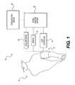
- FIG. 1illustrates a monitoring system, according to an exemplary embodiment.
- FIG. 2illustrates a first flow chart, according to an exemplary embodiment.
- FIG. 3illustrates exemplary oscillometric pulse envelope curves under conditions of minimal arterial stiffness.
- FIG. 4illustrates exemplary oscillometric pulse envelope curves under conditions of increased arterial stiffness.
- FIG. 1illustrates a system 10 , according to an exemplary embodiment of the present disclosure.
- System 10can be configured to monitor a patient, and in some embodiments, to determine a hemodynamic parameter of the patient.
- System 10can include a cuff 12 configured to at least partially occlude the movement of blood through a vessel of patient 14 .
- cuff 12can be configured to completely occlude an artery of patient 14 .
- cuff 12may be adapted for placement on any suitable part of patient 14 , including, for example, a wrist, a finger, an upper thigh, or an ankle.
- one or more cuffs 12could be placed at different locations about patient 14 for use with system 10 .
- Cuff 12can include an inflatable device, wherein the pressure or volume within cuff 12 may be controlled by a cuff controller 16 operably associated with cuff 12 .
- Cuff controller 16can include a pump or similar device to inflate cuff 12 .
- cuff controller 16could supply cuff 12 with a fluid to increase the pressure or volume of cuff 12 .
- cuff controller 16could include mechanical, electrical, or chemical devices configured to control vessel occlusion of patient 14 via cuff 12 .
- System 10can further include a sensor 18 configured to receive a signal associated with patient 14 .
- sensor 18can be configured to receive a signal associated with an at least partially occluded vessel of patient 14 .
- Such an input signalcan arise from blood movement through a partially occluded vessel or from a signal associated with an occluded blood vessel.
- Sensor 18could sample multiple times at various intervals.
- sensor 18could provide an indication of blood vessel movement, such as, for example, oscillations arising from vascular expansion or contraction.
- sensor 18could be configured to detect a pressure or volume of cuff 12 that may vary periodically with the cyclic expansion and contraction of an artery of patient 14 .
- sensor 18could detect a volume or a pressure associated with cuff 12 .
- sensor 18could include a pressure sensor and may be located within or about cuff 12 .
- System 10could further operate with a plurality of sensors 18 , and may include a high-resolution sensor or pneumatic sensor designed to operate in conjunction with cuff 12 .
- Sensor 18can further be configured to generate an output signal.
- the output signalmay be generated based on an input signal received from patient 14 .
- the output signalcan include a representation of an input signal associated with cuff 12 and/or patient 14 .
- system 10can include a signal analysis module 22 .
- Signal analysis module 22may be configured to analyze one or more signals using one or more processors. Such analysis may be based on the output signal of sensor 18 .
- signal analysis module 22can include one or more filters configured to filter a signal associated with sensor 18 or cuff controller 16 . Such filters can include band-pass, band-stop, high-pass, or low-pass filters.
- signal analysis module 22may determine one or more hemodynamic parameters.
- a hemodynamic parametercan include an indication of cardiac or vascular health, such as, for example, an indication of cardiac, circulatory, or vascular functionality.
- a hemodynamic parametercan include a heart rate, a blood pressure, an arterial stiffness, an aortic index, an augmentation index, reflected wave ratio, or an indication of treatment.
- Blood pressurecan include systolic, diastolic, or mean arterial pressure.
- An indication of treatmentcan include a parameter reflecting the effect of a drug treatment, or one or more treatments of a disease state.
- a hemodynamic parametercan be determined based on a first set of data obtained during inflation of cuff 12 and a second set of data obtained during deflation of cuff 12 , as explained below in detail.
- the first or second sets of datacan include various data associated with a signal waveform related to patient 14 and/or cuff 12 , and may include amplitude, frequency, morphology, feature, or mathematically derived data.
- Datacan be derived from a derivative, integration, or frequency analysis, such as, for example, a fast-Fourier transform.
- Datamay also be derived from various algorithms, including curve fitting, neural network, filtering, smoothing, or data processing.
- a hemodynamic parametercan be determined based on a suprasystolic measurement or a combination of inflation, deflation, and suprasystolic measurements.
- System 10can further include an accelerometer 26 to detect movement.
- Accelerometer 26can be configured to detect movement in one, two, or three dimensions.
- accelerometer 26could be used to detect movement of patient 14 or movement of the arm of patient 14 .
- a signal arising from accelerometer 26could be used to provide additional information to another module. For example, if movement of patient 14 is sufficient to interfere with sensor 18 , a signal from accelerometer 26 may be transmitted to signal analysis module 22 to halt the pressure cycle. In addition, a signal from accelerometer 26 may be transmitted to signal analysis module 22 to cancel or reset a calculation. Data obtained from sensor 18 could be combined with data from accelerometer 26 to determine if an irregular signal may be caused by a motion artifact. Various data from accelerometer 26 may be processed to provide additional data to determine one or more hemodynamic parameters.
- System 10can further include a communication module 24 configured to provide communication to patient 14 or one or more operators.
- communication module 24could include a display configured to display one or more hemodynamic parameters.
- communication module 24could include a transmitter configured to transmit data to a remote location.
- Communication module 24may further include audio output to communicate with patient 14 and/or an operator of system 10 .
- system 10may include various other components as required, such as, for example, a memory, a power source, and a user input.
- One or more components described hereinmay be combined or may be separate and operate with wireless or wired communication links.
- the various components of system 10could be integrated into a single processing unit or may operate as separate processors.
- one or more processorscan be configured to operate in conjunction with one or more software programs to provide the functionality of system 10 .
- FIG. 2illustrates a flow chart of an exemplary embodiment according to the present disclosure.
- various modulescan include one or more hardware components and one or more software components that operate to control an operation of system 10 .
- Each step described belowcan be understood as corresponding to one or more computational instructions. These computational instructions can operate based on hardware and/or software components of system 10 , and may operate on one or more processors.
- FIG. 2includes a process 100 according to an exemplary embodiment of the present disclosure.
- Step 110labeled “Start,” may include one or more steps required to initiate an operation of system 10 .
- system 10may be turned on, a calibration protocol may be started, a cuff may be placed about a patient's arm, an operator may enter information to identify a patient, or information could be extracted from a database.
- various components of system 10may be calibrated or tested to ensure proper functioning. These operations could include a check of cuff integrity, a determination of whether sufficient power is available, a calibration of one or more sensors, or confirmation of proper processor functioning.
- other informationmay be entered into system 10 , such as a patient identification, weight, gender, height, or other suitable data.
- cuff controller 16may operate to inflate cuff 12 (Step 112 ) over an inflation period.
- Step 112could be initiated as part of Step 110 .
- sensor 18may detect one or more signals, as discussed above, and generate one or more corresponding output signals to be received by signal analysis module 22 .
- signal analysis module 22may obtain a first set of data (Step 114 ) during at least a portion of the inflation period.
- Cuff controller 16may then operate to deflate cuff 12 (Step 116 ) over a deflation period, and in some embodiments, sensor 18 may detect one or more signals and generate one or more corresponding output signals to be received by signal analysis module 22 .
- signal analysis module 22may obtain a second set of data (Step 118 ) during at least a portion of the deflation period. Once the second set of data has been obtained, signal analysis module 22 may determine a first hemodynamic parameter based on the first and second data sets (Step 120 ).
- process 100may end (Step 124 ). Termination of process 100 can include display of one or more hemodynamic parameters, commencement of another process, and/or power shut-down.
- the first and second sets of datamay comprise oscillometric pulse data.
- the first set of datamay comprise a first oscillometric pulse envelope curve
- the second set of datamay comprise a second oscillometric pulse envelope curve.
- FIGS. 3 and 4illustrate exemplary plots of first oscillometric pulse envelope curve 50 a,b and second oscillometric pulse envelope curve 52 a,b.
- the first oscillometric pulse envelope curvemay differ from the second oscillometric pulse envelope curve as a function of the stiffness of an artery of patient 14 .
- the first oscillometric pulse envelope curveis based on data obtained during the inflation period.
- the amount of force required to compress the arterymay be dependent on a combination of the cuff occlusion efficiency and the amount of force required to overcome any hoop strength of the arterial wall.
- An increase in the stiffness of the arterial wallcan cause an increase in the hoop strength of the arterial wall.
- the second oscillometric pulse envelope curveis based on data obtained during the deflation period.
- the arteryhas already been compressed, so the force required to collapse the artery does not affect the oscillometric pulse envelope curve.
- increased stiffness of the arterial wallcreates a difference between the first oscillometric pulse envelope and the second oscillometric pulse envelope curve.
- FIG. 3depicts a first pulse envelope curve 50 a obtained during inflation and a second pulse envelope curve 52 a obtained during deflation, both measured from an artery having minimal stiffness.
- the peak of the first pulse envelope curve 50 aoccurs at approximately the same cuff pressure as the peak of the second pulse envelope curve 52 a .
- FIG. 4depicts first and second pulse envelope curves measured from an artery having increased stiffness. The increased stiffness results in a shift of the first pulse envelope curve 50 b , which was obtained during inflation, with respect to the second pulse envelope curve 52 b , which was obtained during deflation. This shift indicates that a greater amount of pressure is required to compress the artery during inflation than during deflation.
- the peak of the first pulse envelope curve 50 boccurs at a higher cuff pressure than the peak of the second pulse envelope curve 52 b .
- the value of the difference 54 between cuff pressure at the peak of the first envelope curve and cuff pressure at the peak of the second envelope curvemay indicate the severity of the arterial stiffness.
- signal analysis module 22may determine a first hemodynamic parameter based on comparing the first oscillometric pulse envelope curve to the second oscillometric pulse envelope curve. As discussed above, signal analysis module 22 may compare, for example, amplitude, frequency, morphology, feature, or mathematically derived data of the oscillometric data. In some embodiments, signal analysis module 22 may identify the peaks of the first and second oscillometric pulse envelope curves and determine the difference 54 , if any, in cuff pressure between the two peaks. Thus, signal analysis module 22 may determine atrial stiffness based on the difference 54 between the peaks of the first and second oscillometric pulse envelope curves.
- signal analysis module 22may then determine a second hemodynamic parameter.
- the second hemodynamic parametermay be determined based on the first set of data, the second set of data, an additional set of data, the first hemodynamic parameter, or combinations thereof.
- signal analysis module 22may be configured to calculate arterial stiffness and blood pressure.
- blood pressure measurements from an oscillometric readingcan be influenced by arterial stiffness.
- signal analysis module 22may use a value of arterial stiffness determined to modify or correct blood pressure measurements by accounting for arterial stiffness.
- the order of the inflation and deflation periodsmay vary. For example, in some embodiments, a first set of data may be obtained during an inflation period that occurs after the deflation period during which a second set of data was obtained. Further, in some embodiments, the inflation and deflation periods may occur in close time proximity to each other, but not necessarily consecutively. For example, in some embodiments, the inflation and deflation periods may be separated by one or more other phases of differing cuff pressure and/or duration, such as, for example, a suprasystolic phase.
- the duration of the inflation and deflation periodsmay also vary. In some embodiments the inflation and deflation periods may occur for predetermined amounts of time. Inflation and deflation may also be configured to operate until predetermined pressures are reached. In some embodiments, inflation and deflation may operate until a determination has been made that sufficient information has been obtained. For example, during inflation or deflation, sensor 18 may detect signals for determining if sufficient information has been obtained. The source of this data may be different from the source of the first and second sets of data.
- an algorithm for determining termination of inflation or deflationmay use oscillometric pulse data obtained during the inflation or deflation periods.
- the datamay be analyzed in real time until such a point that an algorithm deems the data sufficient for a reading determination.
- Such datacan relate to the maturity of the pulse envelope or the amount of envelope found during inflation.
- the collected pulse datacan be filtered and/or conditioned.
- a model curvecan be fit to the data.
- datacan be submitted to a trained network of mathematical routines. Such analysis can be used to determine a systolic pressure or a diastolic pressure.
- the SureBP algorithmcould be used to determine a systolic pressure.
- Such an algorithmis described in “Clinical evaluation of the Welch Allyn SureBP algorithm for automated blood pressure measurement,” by Bruce Alpert, which is hereby incorporated by reference in its entirety.
- Such an algorithmcan provide an accurate measure of systolic pressure during inflation, whereby the mean error is less than about 1 mmHg and the standard deviation of the mean error is less than about ⁇ 7 mmHg.
- such an algorithmcould provide a mean error of less than about 5 mmHg and a standard deviation of less than about ⁇ 5 mmHg.
- signal analysis module 22may analyze data being received from sensor 18 in real time and determine when a peak has been reached in an oscillometric pulse envelope curve. When a peak has been reached, signal analysis module 22 may deem sufficient data has been received for determining a hemodynamic parameter and terminate the current inflation or deflation period. For example, only enough data sufficient to identify the peak of the first oscillometric pulse envelope curve and the second oscillometric pulse envelope curve may be necessary to determine arterial stiffness.
- cuff inflation or deflationcan continue until sufficient information has been obtained.
- One or more safety algorithmscould also be used to limit cuff inflation to a maximum pressure.
- inflationmay stop upon reaching a mean arterial pressure, a systolic pressure, or a suprasystolic pressure.
- cuff pressurecan be maintained generally at about a suprasystolic pressure for a period of time. Such maintenance can include minor fluctuations about the target pressure.
- suprasystolic pressureis maintained, one or more hemodynamic parameters may be determined. The one or more hemodynamic parameters may be determined using suprasystolic analysis methods.
- U.S. Patent Application Publication No. 2006/0224070 to Sharrock et al.describes using suprasystolic measurements to determine Augmentation index, cardiac performance and cardiac stroke volume.
- U.S. Patent Application Publication No. 200/0012411 to Lowe et al.describes using oscillometric techniques to analyze suprasystolic signals. Each of these references is hereby incorporated by reference in their entirety.
Landscapes
- Health & Medical Sciences (AREA)
- Life Sciences & Earth Sciences (AREA)
- Cardiology (AREA)
- Vascular Medicine (AREA)
- Biomedical Technology (AREA)
- Heart & Thoracic Surgery (AREA)
- Physiology (AREA)
- Biophysics (AREA)
- Pathology (AREA)
- Engineering & Computer Science (AREA)
- Veterinary Medicine (AREA)
- Physics & Mathematics (AREA)
- Medical Informatics (AREA)
- Molecular Biology (AREA)
- Surgery (AREA)
- Animal Behavior & Ethology (AREA)
- General Health & Medical Sciences (AREA)
- Public Health (AREA)
- Ophthalmology & Optometry (AREA)
- Measuring Pulse, Heart Rate, Blood Pressure Or Blood Flow (AREA)
Abstract
Description
Claims (20)
Priority Applications (3)
| Application Number | Priority Date | Filing Date | Title |
|---|---|---|---|
| US12/787,220US8197414B2 (en) | 2010-05-25 | 2010-05-25 | Systems and methods for measuring arterial stiffness |
| PCT/US2011/027534WO2011149578A1 (en) | 2010-05-25 | 2011-03-08 | Systems and methods for measuring arterial stiffness |
| US13/471,588US9022942B2 (en) | 2010-05-25 | 2012-05-15 | Systems and methods for measuring arterial stiffness |
Applications Claiming Priority (1)
| Application Number | Priority Date | Filing Date | Title |
|---|---|---|---|
| US12/787,220US8197414B2 (en) | 2010-05-25 | 2010-05-25 | Systems and methods for measuring arterial stiffness |
Related Child Applications (1)
| Application Number | Title | Priority Date | Filing Date |
|---|---|---|---|
| US13/471,588ContinuationUS9022942B2 (en) | 2010-05-25 | 2012-05-15 | Systems and methods for measuring arterial stiffness |
Publications (2)
| Publication Number | Publication Date |
|---|---|
| US20110295126A1 US20110295126A1 (en) | 2011-12-01 |
| US8197414B2true US8197414B2 (en) | 2012-06-12 |
Family
ID=45004262
Family Applications (2)
| Application Number | Title | Priority Date | Filing Date |
|---|---|---|---|
| US12/787,220Active2030-12-23US8197414B2 (en) | 2010-05-25 | 2010-05-25 | Systems and methods for measuring arterial stiffness |
| US13/471,588Active2031-06-24US9022942B2 (en) | 2010-05-25 | 2012-05-15 | Systems and methods for measuring arterial stiffness |
Family Applications After (1)
| Application Number | Title | Priority Date | Filing Date |
|---|---|---|---|
| US13/471,588Active2031-06-24US9022942B2 (en) | 2010-05-25 | 2012-05-15 | Systems and methods for measuring arterial stiffness |
Country Status (2)
| Country | Link |
|---|---|
| US (2) | US8197414B2 (en) |
| WO (1) | WO2011149578A1 (en) |
Cited By (3)
| Publication number | Priority date | Publication date | Assignee | Title |
|---|---|---|---|---|
| US9408541B2 (en) | 2014-08-04 | 2016-08-09 | Yamil Kuri | System and method for determining arterial compliance and stiffness |
| US10772571B2 (en) | 2016-11-15 | 2020-09-15 | Welch Allyn, Inc. | Method and systems for correcting for arterial compliance in a blood pressure assessment |
| US11478160B2 (en)* | 2017-12-27 | 2022-10-25 | Omron Healthcare Co., Ltd. | Vital information measuring apparatus, method, and program |
Families Citing this family (8)
| Publication number | Priority date | Publication date | Assignee | Title |
|---|---|---|---|---|
| US9241642B2 (en) | 2012-02-16 | 2016-01-26 | Welch Allyn, Inc. | Systems and methods for monitoring a patient |
| US20130303923A1 (en)* | 2012-05-11 | 2013-11-14 | Biomedix, Inc. | System and method for vascular testing |
| US9301700B2 (en)* | 2012-09-27 | 2016-04-05 | Welch Allyn, Inc. | Configurable vital signs system |
| US11071467B2 (en) | 2013-08-08 | 2021-07-27 | Welch Allyn, Inc. | Hybrid patient monitoring system |
| US9750419B2 (en)* | 2014-02-18 | 2017-09-05 | Welch Allyn, Inc. | Systems and methods for blood pressure measurement |
| WO2016109925A1 (en)* | 2015-01-05 | 2016-07-14 | 深圳迈瑞生物医疗电子股份有限公司 | Blood pressure measuring instrument and air circuit structure thereof, and air circuit box |
| CN105147272B (en)* | 2015-09-10 | 2017-12-26 | 广州视源电子科技股份有限公司 | Blood pressure measuring device and method for measuring blood pressure |
| AU2017269667B2 (en)* | 2016-05-26 | 2021-07-22 | Arjo Ip Holding Ab | Compression therapy system and method |
Citations (16)
| Publication number | Priority date | Publication date | Assignee | Title |
|---|---|---|---|---|
| US5497778A (en) | 1993-06-30 | 1996-03-12 | Hon; Edward H. | Apparatus and method for noninvasive measurement of peripheral pressure pulse compliance and systolic time intervals |
| US5653241A (en) | 1994-08-23 | 1997-08-05 | Colin Corporation | Blood-pressure monitor apparatus |
| US6331159B1 (en) | 1995-11-01 | 2001-12-18 | Seiko Epson Corporation | Device for measuring physiological state |
| US20040024323A1 (en) | 2002-07-31 | 2004-02-05 | Kulik Robert Stanley | Method and apparatus for determining blood pressure using pressure pulse duty cycle |
| US6712768B2 (en) | 2002-01-10 | 2004-03-30 | Colin Corporation | Augmentation-index determining apparatus and arteriosclerosis inspecting apparatus |
| US20040077959A1 (en) | 2002-10-16 | 2004-04-22 | Colin Corporation | Vital-information obtaining apparatus |
| US6733461B2 (en) | 2002-08-01 | 2004-05-11 | Hypertension Diagnostics, Inc. | Methods and apparatus for measuring arterial compliance, improving pressure calibration, and computing flow from pressure data |
| US6793628B2 (en) | 2002-04-17 | 2004-09-21 | Colin Medical Technology Corporation | Blood-pressure measuring apparatus having augmentation-index determining function |
| US6814705B2 (en) | 2002-09-27 | 2004-11-09 | Colin Medical Technology Corporation | Arteriosclerosis-degree evaluating apparatus |
| US6976966B2 (en) | 2002-12-20 | 2005-12-20 | Colin Medical Technology Corporation | Arteriosclerosis evaluating apparatus |
| US6994675B2 (en) | 2000-07-19 | 2006-02-07 | Sharrock Nigel E | Non-invasive measurement of suprasystolic signals |
| US20060229517A1 (en) | 2005-04-11 | 2006-10-12 | Dailycare Biomedical Inc. | Apparatus and method for pulse detection |
| US20070123784A1 (en) | 2005-11-30 | 2007-05-31 | Hersh Lawrence T | Method of controlling blood pressure cuff deflation |
| US20080243009A1 (en) | 2007-03-30 | 2008-10-02 | General Electric Company | Method of controlling inflation of a cuff in blood pressure determination |
| US7468037B2 (en) | 2004-02-18 | 2008-12-23 | Miklos Illyes | Apparatus and method for measuring hemodynamic parameters |
| US20090221924A1 (en) | 2008-02-29 | 2009-09-03 | General Electric Company | Method and system for non-invasive blood pressure determination |
Family Cites Families (1)
| Publication number | Priority date | Publication date | Assignee | Title |
|---|---|---|---|---|
| JP2003047601A (en)* | 2001-05-31 | 2003-02-18 | Denso Corp | Biological abnormality monitoring device, blood pressure monitoring device, biological abnormality monitoring method, and blood pressure monitoring method |
- 2010
- 2010-05-25USUS12/787,220patent/US8197414B2/enactiveActive
- 2011
- 2011-03-08WOPCT/US2011/027534patent/WO2011149578A1/enactiveApplication Filing
- 2012
- 2012-05-15USUS13/471,588patent/US9022942B2/enactiveActive
Patent Citations (16)
| Publication number | Priority date | Publication date | Assignee | Title |
|---|---|---|---|---|
| US5497778A (en) | 1993-06-30 | 1996-03-12 | Hon; Edward H. | Apparatus and method for noninvasive measurement of peripheral pressure pulse compliance and systolic time intervals |
| US5653241A (en) | 1994-08-23 | 1997-08-05 | Colin Corporation | Blood-pressure monitor apparatus |
| US6331159B1 (en) | 1995-11-01 | 2001-12-18 | Seiko Epson Corporation | Device for measuring physiological state |
| US6994675B2 (en) | 2000-07-19 | 2006-02-07 | Sharrock Nigel E | Non-invasive measurement of suprasystolic signals |
| US6712768B2 (en) | 2002-01-10 | 2004-03-30 | Colin Corporation | Augmentation-index determining apparatus and arteriosclerosis inspecting apparatus |
| US6793628B2 (en) | 2002-04-17 | 2004-09-21 | Colin Medical Technology Corporation | Blood-pressure measuring apparatus having augmentation-index determining function |
| US20040024323A1 (en) | 2002-07-31 | 2004-02-05 | Kulik Robert Stanley | Method and apparatus for determining blood pressure using pressure pulse duty cycle |
| US6733461B2 (en) | 2002-08-01 | 2004-05-11 | Hypertension Diagnostics, Inc. | Methods and apparatus for measuring arterial compliance, improving pressure calibration, and computing flow from pressure data |
| US6814705B2 (en) | 2002-09-27 | 2004-11-09 | Colin Medical Technology Corporation | Arteriosclerosis-degree evaluating apparatus |
| US20040077959A1 (en) | 2002-10-16 | 2004-04-22 | Colin Corporation | Vital-information obtaining apparatus |
| US6976966B2 (en) | 2002-12-20 | 2005-12-20 | Colin Medical Technology Corporation | Arteriosclerosis evaluating apparatus |
| US7468037B2 (en) | 2004-02-18 | 2008-12-23 | Miklos Illyes | Apparatus and method for measuring hemodynamic parameters |
| US20060229517A1 (en) | 2005-04-11 | 2006-10-12 | Dailycare Biomedical Inc. | Apparatus and method for pulse detection |
| US20070123784A1 (en) | 2005-11-30 | 2007-05-31 | Hersh Lawrence T | Method of controlling blood pressure cuff deflation |
| US20080243009A1 (en) | 2007-03-30 | 2008-10-02 | General Electric Company | Method of controlling inflation of a cuff in blood pressure determination |
| US20090221924A1 (en) | 2008-02-29 | 2009-09-03 | General Electric Company | Method and system for non-invasive blood pressure determination |
Non-Patent Citations (5)
| Title |
|---|
| Alpert, B.S. "Clinical evaluation of the Welch Allyn SureBP algorithm for automated blood pressure measurement" Blood Pressure Monitoring 12(4):215-218 (2007). |
| Gelida, G., et al. "Arterial pressure measurement: Is the envelope curve of the oscillometric method influenced by arterial stiffness?" J. Phys.:Conf. Ser. 90 012053 (2007). |
| International Search Report and Written Opinion for International Application No. PCT/US11/27534, dated Sep. 28, 2011, 8 pages. |
| MacKenzie, I.S., et al. "Assessment of arterial stiffness in clinical practice" Q.J. Med 95:67-74 (2002). |
| McLaughlin, J. et al., "Piezoelectric sensor determination of arterial pulse wave velocity," Physiol. Meas., 24:693-702 (2003). |
Cited By (3)
| Publication number | Priority date | Publication date | Assignee | Title |
|---|---|---|---|---|
| US9408541B2 (en) | 2014-08-04 | 2016-08-09 | Yamil Kuri | System and method for determining arterial compliance and stiffness |
| US10772571B2 (en) | 2016-11-15 | 2020-09-15 | Welch Allyn, Inc. | Method and systems for correcting for arterial compliance in a blood pressure assessment |
| US11478160B2 (en)* | 2017-12-27 | 2022-10-25 | Omron Healthcare Co., Ltd. | Vital information measuring apparatus, method, and program |
Also Published As
| Publication number | Publication date |
|---|---|
| US9022942B2 (en) | 2015-05-05 |
| US20110295126A1 (en) | 2011-12-01 |
| WO2011149578A1 (en) | 2011-12-01 |
| US20120226173A1 (en) | 2012-09-06 |
Similar Documents
| Publication | Publication Date | Title |
|---|---|---|
| US8197414B2 (en) | Systems and methods for measuring arterial stiffness | |
| US8840561B2 (en) | Suprasystolic measurement in a fast blood-pressure cycle | |
| Alpert et al. | Oscillometric blood pressure: a review for clinicians | |
| CN109414199B (en) | Apparatus and method for non-invasive assessment of maximum arterial compliance | |
| US10165984B2 (en) | Configurable vital signs system | |
| US11406272B2 (en) | Systems and methods for blood pressure measurement | |
| US11484274B2 (en) | Systems and methods for monitoring a patient | |
| WO2018167728A1 (en) | Central aortic blood pressure and waveform calibration method | |
| US7497831B2 (en) | Blood pressure measuring system and method | |
| CN104042200A (en) | Non-invasive monitoring device and method for beat-to-beat arterial blood pressure | |
| US9211070B2 (en) | Evaluation of peripheral arterial disease in a patient using an oscillometric pressure signal obtained at a lower extremity of the patient | |
| US9375150B2 (en) | Identification of pressure cuff conditions using frequency content of an oscillometric pressure signal | |
| EP3705033A1 (en) | Blood pressure measurement device and control method | |
| US20170196468A1 (en) | Method for an Accurate Automated Non-invasive Measurement of Blood Pressure Waveform and Apparatus to Carry Out the Same |
Legal Events
| Date | Code | Title | Description |
|---|---|---|---|
| AS | Assignment | Owner name:WELCH ALLYN, INC., NEW YORK Free format text:ASSIGNMENT OF ASSIGNORS INTEREST;ASSIGNORS:QUINN, DAVID E.;WHITAKER, TYSON B.;KINSLEY, MATT;AND OTHERS;SIGNING DATES FROM 20100524 TO 20100525;REEL/FRAME:024441/0366 | |
| FEPP | Fee payment procedure | Free format text:PAYOR NUMBER ASSIGNED (ORIGINAL EVENT CODE: ASPN); ENTITY STATUS OF PATENT OWNER: LARGE ENTITY | |
| STCF | Information on status: patent grant | Free format text:PATENTED CASE | |
| AS | Assignment | Owner name:JPMORGAN CHASE BANK, N.A., AS COLLATERAL AGENT, ILLINOIS Free format text:SECURITY INTEREST;ASSIGNORS:ALLEN MEDICAL SYSTEMS, INC.;HILL-ROM SERVICES, INC.;ASPEN SURGICAL PRODUCTS, INC.;AND OTHERS;REEL/FRAME:036582/0123 Effective date:20150908 Owner name:JPMORGAN CHASE BANK, N.A., AS COLLATERAL AGENT, IL Free format text:SECURITY INTEREST;ASSIGNORS:ALLEN MEDICAL SYSTEMS, INC.;HILL-ROM SERVICES, INC.;ASPEN SURGICAL PRODUCTS, INC.;AND OTHERS;REEL/FRAME:036582/0123 Effective date:20150908 | |
| FPAY | Fee payment | Year of fee payment:4 | |
| AS | Assignment | Owner name:JPMORGAN CHASE BANK, N.A., AS COLLATERAL AGENT, ILLINOIS Free format text:SECURITY AGREEMENT;ASSIGNORS:HILL-ROM SERVICES, INC.;ASPEN SURGICAL PRODUCTS, INC.;ALLEN MEDICAL SYSTEMS, INC.;AND OTHERS;REEL/FRAME:040145/0445 Effective date:20160921 Owner name:JPMORGAN CHASE BANK, N.A., AS COLLATERAL AGENT, IL Free format text:SECURITY AGREEMENT;ASSIGNORS:HILL-ROM SERVICES, INC.;ASPEN SURGICAL PRODUCTS, INC.;ALLEN MEDICAL SYSTEMS, INC.;AND OTHERS;REEL/FRAME:040145/0445 Effective date:20160921 | |
| AS | Assignment | Owner name:HILL-ROM SERVICES, INC., ILLINOIS Free format text:RELEASE BY SECURED PARTY;ASSIGNOR:JPMORGAN CHASE BANK, N.A.;REEL/FRAME:050254/0513 Effective date:20190830 Owner name:MORTARA INSTRUMENT SERVICES, INC., WISCONSIN Free format text:RELEASE BY SECURED PARTY;ASSIGNOR:JPMORGAN CHASE BANK, N.A.;REEL/FRAME:050254/0513 Effective date:20190830 Owner name:ANODYNE MEDICAL DEVICE, INC., FLORIDA Free format text:RELEASE BY SECURED PARTY;ASSIGNOR:JPMORGAN CHASE BANK, N.A.;REEL/FRAME:050254/0513 Effective date:20190830 Owner name:HILL-ROM, INC., ILLINOIS Free format text:RELEASE BY SECURED PARTY;ASSIGNOR:JPMORGAN CHASE BANK, N.A.;REEL/FRAME:050254/0513 Effective date:20190830 Owner name:WELCH ALLYN, INC., NEW YORK Free format text:RELEASE BY SECURED PARTY;ASSIGNOR:JPMORGAN CHASE BANK, N.A.;REEL/FRAME:050254/0513 Effective date:20190830 Owner name:MORTARA INSTRUMENT, INC., WISCONSIN Free format text:RELEASE BY SECURED PARTY;ASSIGNOR:JPMORGAN CHASE BANK, N.A.;REEL/FRAME:050254/0513 Effective date:20190830 Owner name:HILL-ROM COMPANY, INC., ILLINOIS Free format text:RELEASE BY SECURED PARTY;ASSIGNOR:JPMORGAN CHASE BANK, N.A.;REEL/FRAME:050254/0513 Effective date:20190830 Owner name:VOALTE, INC., FLORIDA Free format text:RELEASE BY SECURED PARTY;ASSIGNOR:JPMORGAN CHASE BANK, N.A.;REEL/FRAME:050254/0513 Effective date:20190830 Owner name:ALLEN MEDICAL SYSTEMS, INC., ILLINOIS Free format text:RELEASE BY SECURED PARTY;ASSIGNOR:JPMORGAN CHASE BANK, N.A.;REEL/FRAME:050254/0513 Effective date:20190830 | |
| AS | Assignment | Owner name:JPMORGAN CHASE BANK, N.A., ILLINOIS Free format text:SECURITY AGREEMENT;ASSIGNORS:HILL-ROM HOLDINGS, INC.;HILL-ROM, INC.;HILL-ROM SERVICES, INC.;AND OTHERS;REEL/FRAME:050260/0644 Effective date:20190830 | |
| MAFP | Maintenance fee payment | Free format text:PAYMENT OF MAINTENANCE FEE, 8TH YEAR, LARGE ENTITY (ORIGINAL EVENT CODE: M1552); ENTITY STATUS OF PATENT OWNER: LARGE ENTITY Year of fee payment:8 | |
| AS | Assignment | Owner name:HILL-ROM HOLDINGS, INC., ILLINOIS Free format text:RELEASE OF SECURITY INTEREST AT REEL/FRAME 050260/0644;ASSIGNOR:JPMORGAN CHASE BANK, N.A.;REEL/FRAME:058517/0001 Effective date:20211213 Owner name:BARDY DIAGNOSTICS, INC., ILLINOIS Free format text:RELEASE OF SECURITY INTEREST AT REEL/FRAME 050260/0644;ASSIGNOR:JPMORGAN CHASE BANK, N.A.;REEL/FRAME:058517/0001 Effective date:20211213 Owner name:VOALTE, INC., FLORIDA Free format text:RELEASE OF SECURITY INTEREST AT REEL/FRAME 050260/0644;ASSIGNOR:JPMORGAN CHASE BANK, N.A.;REEL/FRAME:058517/0001 Effective date:20211213 Owner name:HILL-ROM, INC., ILLINOIS Free format text:RELEASE OF SECURITY INTEREST AT REEL/FRAME 050260/0644;ASSIGNOR:JPMORGAN CHASE BANK, N.A.;REEL/FRAME:058517/0001 Effective date:20211213 Owner name:WELCH ALLYN, INC., NEW YORK Free format text:RELEASE OF SECURITY INTEREST AT REEL/FRAME 050260/0644;ASSIGNOR:JPMORGAN CHASE BANK, N.A.;REEL/FRAME:058517/0001 Effective date:20211213 Owner name:ALLEN MEDICAL SYSTEMS, INC., ILLINOIS Free format text:RELEASE OF SECURITY INTEREST AT REEL/FRAME 050260/0644;ASSIGNOR:JPMORGAN CHASE BANK, N.A.;REEL/FRAME:058517/0001 Effective date:20211213 Owner name:HILL-ROM SERVICES, INC., ILLINOIS Free format text:RELEASE OF SECURITY INTEREST AT REEL/FRAME 050260/0644;ASSIGNOR:JPMORGAN CHASE BANK, N.A.;REEL/FRAME:058517/0001 Effective date:20211213 Owner name:BREATHE TECHNOLOGIES, INC., CALIFORNIA Free format text:RELEASE OF SECURITY INTEREST AT REEL/FRAME 050260/0644;ASSIGNOR:JPMORGAN CHASE BANK, N.A.;REEL/FRAME:058517/0001 Effective date:20211213 | |
| MAFP | Maintenance fee payment | Free format text:PAYMENT OF MAINTENANCE FEE, 12TH YEAR, LARGE ENTITY (ORIGINAL EVENT CODE: M1553); ENTITY STATUS OF PATENT OWNER: LARGE ENTITY Year of fee payment:12 |