US8197276B2 - Low profile connector system - Google Patents
Low profile connector systemDownload PDFInfo
- Publication number
- US8197276B2 US8197276B2US12/856,382US85638210AUS8197276B2US 8197276 B2US8197276 B2US 8197276B2US 85638210 AUS85638210 AUS 85638210AUS 8197276 B2US8197276 B2US 8197276B2
- Authority
- US
- United States
- Prior art keywords
- receptacle
- electrically conductive
- conductive element
- housing
- low profile
- Prior art date
- Legal status (The legal status is an assumption and is not a legal conclusion. Google has not performed a legal analysis and makes no representation as to the accuracy of the status listed.)
- Active
Links
- 238000000034methodMethods0.000claimsdescription14
- 210000003205muscleAnatomy0.000claimsdescription4
- 210000005036nerveAnatomy0.000claimsdescription3
- 230000004044responseEffects0.000claimsdescription3
- 230000004936stimulating effectEffects0.000claimsdescription3
- 230000001154acute effectEffects0.000claimsdescription2
- 210000002414legAnatomy0.000description48
- 230000000638stimulationEffects0.000description12
- 238000011282treatmentMethods0.000description12
- 230000037307sensitive skinEffects0.000description5
- 208000027418Wounds and injuryDiseases0.000description4
- 238000004891communicationMethods0.000description4
- ORQBXQOJMQIAOY-UHFFFAOYSA-NnobeliumChemical compound[No]ORQBXQOJMQIAOY-UHFFFAOYSA-N0.000description4
- 229910000831SteelInorganic materials0.000description3
- 206010052428WoundDiseases0.000description3
- 238000010586diagramMethods0.000description3
- 239000000463materialSubstances0.000description3
- 230000007246mechanismEffects0.000description3
- 238000012986modificationMethods0.000description3
- 230000004048modificationEffects0.000description3
- 239000010959steelSubstances0.000description3
- 210000001519tissueAnatomy0.000description3
- 210000000689upper legAnatomy0.000description3
- 239000000853adhesiveSubstances0.000description2
- 238000004873anchoringMethods0.000description2
- 230000009286beneficial effectEffects0.000description2
- 230000002354daily effectEffects0.000description2
- 230000000694effectsEffects0.000description2
- 238000003780insertionMethods0.000description2
- 230000037431insertionEffects0.000description2
- 230000008569processEffects0.000description2
- 238000002560therapeutic procedureMethods0.000description2
- 230000000007visual effectEffects0.000description2
- RYGMFSIKBFXOCR-UHFFFAOYSA-NCopperChemical compound[Cu]RYGMFSIKBFXOCR-UHFFFAOYSA-N0.000description1
- 229910000639Spring steelInorganic materials0.000description1
- 230000006978adaptationEffects0.000description1
- 238000007792additionMethods0.000description1
- 230000001070adhesive effectEffects0.000description1
- 239000002313adhesive filmSubstances0.000description1
- 230000004075alterationEffects0.000description1
- 238000013459approachMethods0.000description1
- 244000309466calfSpecies0.000description1
- 230000003750conditioning effectEffects0.000description1
- 229910052802copperInorganic materials0.000description1
- 239000010949copperSubstances0.000description1
- 230000006378damageEffects0.000description1
- 230000007812deficiencyEffects0.000description1
- 230000000994depressogenic effectEffects0.000description1
- 239000013013elastic materialSubstances0.000description1
- 238000005516engineering processMethods0.000description1
- 230000003203everyday effectEffects0.000description1
- 208000014674injuryDiseases0.000description1
- 238000004519manufacturing processMethods0.000description1
- 230000013011matingEffects0.000description1
- 239000002184metalSubstances0.000description1
- 229910052751metalInorganic materials0.000description1
- 239000007769metal materialSubstances0.000description1
- 238000003032molecular dockingMethods0.000description1
- 229920000642polymerPolymers0.000description1
- 230000002980postoperative effectEffects0.000description1
- 230000002028prematureEffects0.000description1
- 230000000069prophylactic effectEffects0.000description1
- 229910052709silverInorganic materials0.000description1
- 239000004332silverSubstances0.000description1
- 238000005728strengtheningMethods0.000description1
- 238000006467substitution reactionMethods0.000description1
- 238000012546transferMethods0.000description1
- 230000029663wound healingEffects0.000description1
Images


Classifications
- A—HUMAN NECESSITIES
- A61—MEDICAL OR VETERINARY SCIENCE; HYGIENE
- A61N—ELECTROTHERAPY; MAGNETOTHERAPY; RADIATION THERAPY; ULTRASOUND THERAPY
- A61N1/00—Electrotherapy; Circuits therefor
- A61N1/02—Details
- A61N1/04—Electrodes
- A61N1/0404—Electrodes for external use
- A61N1/0472—Structure-related aspects
- A61N1/048—Electrodes characterised by a specific connection between lead and electrode
- H—ELECTRICITY
- H01—ELECTRIC ELEMENTS
- H01R—ELECTRICALLY-CONDUCTIVE CONNECTIONS; STRUCTURAL ASSOCIATIONS OF A PLURALITY OF MUTUALLY-INSULATED ELECTRICAL CONNECTING ELEMENTS; COUPLING DEVICES; CURRENT COLLECTORS
- H01R13/00—Details of coupling devices of the kinds covered by groups H01R12/70 or H01R24/00 - H01R33/00
- H01R13/46—Bases; Cases
- H01R13/502—Bases; Cases composed of different pieces
- H—ELECTRICITY
- H01—ELECTRIC ELEMENTS
- H01R—ELECTRICALLY-CONDUCTIVE CONNECTIONS; STRUCTURAL ASSOCIATIONS OF A PLURALITY OF MUTUALLY-INSULATED ELECTRICAL CONNECTING ELEMENTS; COUPLING DEVICES; CURRENT COLLECTORS
- H01R13/00—Details of coupling devices of the kinds covered by groups H01R12/70 or H01R24/00 - H01R33/00
- H01R13/62—Means for facilitating engagement or disengagement of coupling parts or for holding them in engagement
- H01R13/629—Additional means for facilitating engagement or disengagement of coupling parts, e.g. aligning or guiding means, levers, gas pressure electrical locking indicators, manufacturing tolerances
- H01R13/631—Additional means for facilitating engagement or disengagement of coupling parts, e.g. aligning or guiding means, levers, gas pressure electrical locking indicators, manufacturing tolerances for engagement only
- H—ELECTRICITY
- H01—ELECTRIC ELEMENTS
- H01R—ELECTRICALLY-CONDUCTIVE CONNECTIONS; STRUCTURAL ASSOCIATIONS OF A PLURALITY OF MUTUALLY-INSULATED ELECTRICAL CONNECTING ELEMENTS; COUPLING DEVICES; CURRENT COLLECTORS
- H01R13/00—Details of coupling devices of the kinds covered by groups H01R12/70 or H01R24/00 - H01R33/00
- H01R13/62—Means for facilitating engagement or disengagement of coupling parts or for holding them in engagement
- H01R13/629—Additional means for facilitating engagement or disengagement of coupling parts, e.g. aligning or guiding means, levers, gas pressure electrical locking indicators, manufacturing tolerances
- H01R13/633—Additional means for facilitating engagement or disengagement of coupling parts, e.g. aligning or guiding means, levers, gas pressure electrical locking indicators, manufacturing tolerances for disengagement only
- H01R13/635—Additional means for facilitating engagement or disengagement of coupling parts, e.g. aligning or guiding means, levers, gas pressure electrical locking indicators, manufacturing tolerances for disengagement only by mechanical pressure, e.g. spring force
- A—HUMAN NECESSITIES
- A61—MEDICAL OR VETERINARY SCIENCE; HYGIENE
- A61N—ELECTROTHERAPY; MAGNETOTHERAPY; RADIATION THERAPY; ULTRASOUND THERAPY
- A61N1/00—Electrotherapy; Circuits therefor
- A61N1/18—Applying electric currents by contact electrodes
- A61N1/32—Applying electric currents by contact electrodes alternating or intermittent currents
- A61N1/36—Applying electric currents by contact electrodes alternating or intermittent currents for stimulation
- A61N1/36014—External stimulators, e.g. with patch electrodes
Definitions
- Electro-stimulationis widely used for pain relief, for muscle strengthening and conditioning, wound healing, and other medical rehabilitative and prophylactic purposes.
- An electrodee.g., adhesive electrode
- the electrodeis connected to a wire that connects to a stimulator.
- Current devicestend to be bulky and have wires that get tangled or in the way of the user, which is intrusive to the user's daily activities. Due to the bulkiness of the device, it is also difficult to wear the device under clothing.
- a vertical forcecan be painful when applied to electrodes used to treat tissue that has been burned or otherwise injured or subject to pain.
- the systems and methods described hereinaddress the deficiencies in the prior art by providing low profile electrical connectors for connecting to an electro-stimulation interface having an improved connection mechanism that is easier to use, less intrusive to the user's daily activities, and less painful to apply to injured tissue.
- Methods of manufacturing such connectorsare also disclosed.
- the systems disclosed hereinprovide an electrical connector having a first side-entry portal as part of the connector housing, which portal receives an electrically conductive element, such as an electrode, and guides it within the housing along a path that generally extends parallel to the user treatment site. That configuration facilitates a lower profile connection system that is easier to use and also potentially less painful to users who have suffered severe burns or other injuries or pain.
- a low profile electrical connectoris provided with a housing having exterior perimeter sides, top and bottom surfaces and a side-entry guide channel disposed along the bottom surface.
- An opening configured to receive the electrically conductive elementis disposed along the exterior perimeter side and in communication with the channel.
- the channelguides the electrically conductive element within the housing.
- the connectoralso includes a receptacle positioned within the housing and having an electrically conductive surface that forms an interface with the electrically conductive element.
- the connectorincludes a plurality of side-entry portals along an exterior perimeter side for receiving the electrically conductive element.
- the housingincludes a transceiver that is configured to receive and/or transmit signals to a control device for stimulating muscle or nerve.
- the low-profile connector system described hereinis configured to laterally engage the electrically conductive element.
- the connector systemis preferably configured to be controlled wirelessly.
- a plurality of connector systemsare used, which may be connected by a flexible cable or wire.
- the improved connector systemallows a user with sensitive skin or wound to connect the stimulation device to the electrically conductive element positioned on sensitive skin areas without applying vertical connecting force.
- the connectoralso includes a release actuator that is operatively engaged to the receptacle and configured to extend a force along a plane substantially parallel with the guide channel to disengage the electrode or other electrically conductive element from the receptacle.
- a release actuatorthat is operatively engaged to the receptacle and configured to extend a force along a plane substantially parallel with the guide channel to disengage the electrode or other electrically conductive element from the receptacle.
- the electrically conductive elementis removed from the receptacle when the housing is pulled away from the electrically conductive element along the guide channel.
- the side-entry guide channelmay be formed at least in part by an interior wall that extends from the opening towards the receptacle.
- pulling the receptacle away from the electrically conductive element along the guide channeldisengages and removes the electrically conductive element from the receptacle.
- the guide channelis defined at least in part by the bottom surface of the housing, and during disengagement the housing is pulled away from the electrically conductive element along an interior wall.
- the guide channelmay include a path that tapers within the receptacle.
- the receptacle of the connectorincludes one or more compressible legs that are operable by a release actuation to adjust the size of the channel and, thereby, insertion and release of the electrically conductive element.
- the connectorincludes an upper leg, a vertically disposed post leg, and a leading leg configured to guide the electrically conductive element from the side-entry guide channel.
- the vertically disposed post legsare spaced apart from one another and configured to maintain space between the legs throughout operation.
- a connectoris provided with a release actuator configured to release the electrically conductive element from the receptacle.
- the release actuatoris laterally engaged to the receptacle and adapted to move the upper legs of the receptacle away from one another in response to the actuation of the release actuator.
- the side-entry guide channelextends between the leading leg and the upper leg.
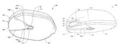
- FIG. 1Adepicts an electrode placed on a user's body and a connector configured to engage the electrode.
- FIG. 1Bdepicts an exemplary mating relationship between the electrode and the connector of FIG. 1A .
- FIG. 2Ashows a bottom-perspective view of an exemplary electrode connector.
- FIG. 2Bshows a bottom view of an alternative embodiment of an exemplary electrode connector.
- FIG. 2Cshows a bottom view of an alternative embodiment of an exemplary electrode connector.
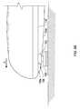
- FIG. 3shows a front view of the connector of FIG. 2A .
- FIG. 4shows a top-perspective view of the connector of FIG. 3 without a top cover.
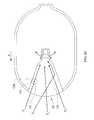
- FIG. 5shows a bottom-perspective view of a receptacle connected to a electrode connector.
- FIGS. 6A-6Cshow various views of an electrode connector engaging an electrode, according to illustrative embodiments.
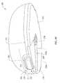
- FIG. 7shows the electrode of FIG. 5 received within a connector.
- FIG. 8shows the connector and electrode of FIG. 7 being disengaged from one another.
- FIG. 9Ashows an alternative embodiment of a connector having a release actuator engaging an electrode.
- FIG. 9Bshows a bottom-perspective view of the connector of FIG. 9A .
- FIG. 9Cshows a top-perspective view of the connector as shown in FIG. 9B without a top cover.
- FIG. 9Dshows a perspective view of an exemplary receptacle housed within the connector of FIG. 9C .
- FIG. 9Eshows a top-perspective view of the connector of FIG. 9C with the release actuator depressed.
- FIG. 10is a block diagram of an illustrative electrostimulation system.
- connection systemsthat allow a simple yet effective connection between electrically conductive element, such as an electrode, and an electro-stimulation device.
- electrically conductive elementsuch as an electrode
- an electro-stimulation devicesuch as an electrode
- a low-profile connectorthat laterally engages an electrically conductive element (such as a snap electrode) is described.
- a lateral connectionallows a clinician or user to engage the low-profile connector to an electrically conductive element placed on a user's body site by applying a force parallel directly to the body site. This may be particularly useful and beneficial to users with sensitive skin such as post-operative or burn patients.
- FIG. 1Ashows an exemplary embodiment of a low profile connector 100 positioned to laterally engage an electrically conductive element 102 placed on the back of a user's calf.
- Some usersmay have difficulty connecting the connector 100 to electrodes or other electrically conductive elements placed in areas that are not easily visible or accessible.
- the connector 100engages the electrically conductive element 102 along the surface of the user's skin in direction noted by Arrow A. Connection along that path may be easier to perform than along a vertical path.
- the electrically conductive element 102is a snap-type electrode having an active surface 103 which may be coated with a self-adhesive material or self-adhesive film (not shown) that sticks to a user's body site.
- the element 102may alternatively be a sensor, or other conductive element, such as conductive embroidery in a user's clothing, provided it is positioned and configured with a stud or other conductive interface that enables it to make electrical contact with the connector 100 .
- Exemplary conductive embroidery elementsmay include silver, copper or other metal (or conduct polymer) sewn or glued to the surface of a user garment, such as an exercise sock, t-shirt, or a brace, and having a stud or other conductive surface exposed and positioned to mate with the connector 100 .
- the electrode 102is manufactured to have metallic or other conductive extensions from its sides, which extensions fit within pockets in the garment or are sewn within the garment, while the stud remains exposed for connection to the connector 100 .
- the electrically conductive element shown as element (depicted as an electrode) 102may be disposable or reusable depending on a particular treatment protocol or condition to be treated.
- the electrode 102also includes a stud portion 104 that protrudes from the active surface 103 for making electrical connection with the connector 100 .
- the connector 100is depicted in FIG. 1B in relation to a plane 105 that extends axially through the connector and substantially parallel to the user's body site. As shown in FIG. 1B , the connector 100 travels laterally along the plane 105 in direction A until the electrode 102 engages within the connector 100 . In certain implementations the connector contacts the user's tissue during lateral engagement, while in others the connector moves parallel to the user's body site but remains above it, without contacting the body site.
- the connector 100includes a housing 106 having exterior perimeter side 112 that extend around the perimeter of the housing 106 , a bottom surface 110 configured to extend along or parallel to a user's body site (such as the skin surface), and a top surface 108 spaced above the bottom surface 110 .
- the connector 100also includes a side-entry guide channel 114 defined at least in part by the bottom surface 110 of the housing 106 .
- the guide channel 114is adapted to self-guide the connector 100 with respect to the electrode 102 .
- the guide channel 114includes an opening 120 positioned along the exterior perimeter side 112 for receiving and guiding the electrode 102 within the housing 106 .
- the guide channel 114extends from the opening 120 to a receptacle pocket 122 of the housing 106 .
- the receptacle pocket 122houses a receptacle 116 and is formed on the bottom surface 110 of the housing 106 .
- the receptacle 116is disposed within the housing 106 and includes an electrically conductive element that receives the electrode 102 forming an electrical/mechanical connection between the electrode 102 and the connector 100 , as described more fully below.
- the connectorincludes more than one side-entry guide channel.
- a connector 100 aincludes a plurality of guide channels 114 disposed along the exterior perimeter side 112 for receiving an electrically conductive element such as an electrode.
- the connector 100 amay include two, three or more guide channels depending on the treatment protocol or condition to be treated. Having a plurality of guide channels allows the user to engage an electrically conductive element (e.g., an electrode) in multiple ways, which may improve usability and user satisfaction.
- FIG. 2Cillustrates an example having a connector 100 b including a plurality of guide channels 114 leading to a single receptacle 116 a .
- the receptacle 116 aincludes first and second openings 117 a and 117 b , respectively, for receiving an electrically conductive element such as an electrode.
- the side entry guide channel 114is defined at least in part by the interior walls 130 a and 130 b that extend from the opening 120 towards the receptacle 116 . As shown, the interior walls 130 a and 130 b form a V-shaped path that tapers into the receptacle 116 . Such configuration allows the user to guide the electrode 102 within the housing 106 , as the interior walls 130 a or 130 b slide against the stud 104 when the housing 106 moves laterally in direction A (as shown in FIG. 1B ).
- the guide channel 114also includes angled regions 132 a and 132 b of walls 130 a and 130 b , respectively, that further guide the electrode within the housing 106 .
- FIG. 1BThe guide channel 114 also includes angled regions 132 a and 132 b of walls 130 a and 130 b , respectively, that further guide the electrode within the housing 106 .
- FIG 3which depicts a front view of the housing 106 , shows the angled wall regions 132 a and 132 b extending from respective end points 131 a and 131 b of the respective interior walls 130 a and 130 b to the receptacle pocket 122 .
- the angled walls 132 a and 132 breceive the stud 104 as the stud 104 travels along the interior wall 130 a or 130 b and further guide the stud 104 into the receptacle 116 .
- the height h 1 of the interior walls 130 a and 130 bincreases from the opening 120 to height h 2 near the angled walls 132 a and 132 b .
- the guide channel 114also includes an upper guiding surface 136 that is partly defined by the interior and angled walls.
- the upper guiding surface 136 and the interior and angled wallsform a space for receiving and guiding the electrode 102 within the connector 100 .
- the upper guiding surface 136may extend at an angle with respect to the bottom surface 110 of the housing 106 , or it may also extend substantially parallel to the bottom surface 110 of the housing 106 .
- the housing 106includes an angled bottom surface 111 that coextends with the bottom surface 110 .
- the angled bottom surface 111slopes upwardly from the middle portion of the housing 106 towards the opening 120 .
- FIG. 3shows an embodiment of the angled bottom surface 111 .
- the angled bottom surface 111may allow the user to better engage the electrode 102 by allowing for more ergonomic placement of the connector 100 . For example, when the user first places and slides the angled bottom surface 111 against the user's skin surface, the user may hold the connector 100 at an angle with respect to the user's skin surface. This may be more natural or ergonomic to some users.
- FIG. 4shows a top-perspective view of the housing 106 .
- the housing 106is shown without the inner electronic components (e.g., PCB, battery).
- the housing 106includes a receptacle connector 126 that connects the receptacle 116 to the housing 106 .
- the receptacle connector 126is a separate component and includes holes 128 a and 128 b that receive the receptacle to the housing 106 .
- the receptacle connector 126is also shaped to follow the contour of the top surface 108 of the housing 106 .
- the receptacle connector 126mates with a plurality of positioning posts 133 a - 133 f , which are affixed to the housing 106 .
- the receptacle connector 126may be made of metallic material that can transfer electrical pulses from a controller (not shown) to the receptacle 116 .
- the receptacle 116includes one or more compressible legs that are operable by a release actuation to adjust the size of the channel and, thereby, insertion and release of the electrode.
- the receptacle 116includes a pair of guide legs 140 a and 140 b , an electrode receiving pocket 138 for receiving and making electrical connection with the stud 104 , and a neck portion 139 that bridges the guide legs to the electrode receiving pocket 138 .
- the guide legs 140 a and 140 b and the electrode receiving pocket 138are depicted in relation to a plane 142 , which is substantially parallel to the bottom surface 110 of the housing 106 .
- the guide legs 140 a and 140 btaper from their respective open ends 141 a and 141 b toward the neck portion 139 . This shape helps to channel the stud 104 towards the electrode receiving pocket 138 during the engagement process.
- the receptacle 116is made of spring steel wire that opens and closes responsive to the direction and the amount of the force applied. For example, as the stud 104 travels along the guide legs 140 a and 140 b , the stud 104 forces open the guide legs 140 a and 140 b slightly outwardly to create space for the stud 104 to travel and enter the electrode receiving pocket 138 .
- the receptacle 116also includes a pair of vertical post legs 144 a and 144 b that extend perpendicular to the working plane 142 and a pair of upper legs 146 a and 146 b that connect the vertical post legs 144 a and 144 b to the receptacle connector 126 .
- These vertical post legsare spaced apart from one another initially and are configured to maintain space between the legs throughout operation.
- the upper legs 146 a and 146 bare received by holes 128 a and 128 b and extend substantially parallel to the working plane 142 .
- the guide channel 114extends between the guide legs 140 a and 140 b and the upper legs 146 a and 146 b.
- FIG. 6Ashows a perspective view of the connector 100 ready to engage the electrode 102 .
- the housing 106includes an entry region 134 defined by the side entry guide channel 114 with opening 120 .
- the entry region 134receives the electrode 102 when the user initially engages the connector 100 to the electrode 102 .
- the entry region 134is shaped to capture the stud 104 without the user having to closely align the connector 100 with respect to the electrode 102 .
- the userbrings the connector 100 near the electrode 102 and slides the connector 100 laterally towards the electrode 102 so that stud 104 passes through opening 120 .
- the electrode 102is received by the entry region 134 , which extends widely along the exterior perimeter side 112 , allowing the user to roughly position the connector 100 with respect to the electrode 102 .
- the entry region 134has a large width, the user does not need to be precise when initially engaging the connector 100 to the electrode 102 . This is especially helpful for users who have reduced mobility/dexterity or if the body site is located where visual contact is difficult.
- the channelfacilitates the seating of the electrode within the connector 100 through various exemplary mechanisms.
- a top surface 150 of the stud 104engages an upper guiding surface 136 of the guide channel 114 , as shown in FIG. 6B .
- the upper guiding surface 136 of the connector 100moves along the top surface 150 of the stud 104 .
- the interior walls 130 a and 130 bmay also act as a “rail” for the stud 104 to travel, which gives the user the feeling of tracking or guiding during the engagement process. As shown, for example, in FIG.
- a side surface 152 of the stud 104may initially engage a narrow end 129 a of the interior wall 130 a and travels along the interior wall 130 a (path P 3 ).
- the stud 104may similarly travel along the interior wall 130 b and angled wall region 132 b , as depicted by path P 1 shown in FIG. 6C .
- the stud 104may travel straight into the receptacle 116 without engaging the interior or the angled walls.
- the electrode 102may also travel along a curved path. These paths are depicted for illustrative purpose only. The electrode 102 may travel in any combination of straight and curved paths within the guide channel 114 .
- the usermay hear an audible click or, in some embodiments, a visual indicator (e.g., ON/OFF light) provided on the top cover 118 of the connector 100 to indicate that the device is ready to be used.
- a visual indicatore.g., ON/OFF light
- FIG. 7shows an exemplary bottom view of the electrode 102 fully engaged to the receptacle 116 that is housed within the connector 100 .
- the stud portion 104 of the electrodeis sized such that it can be received within the electrode receiving pocket 138 of receptacle 116 .
- the shape and size of the electrode receiving pocket 138secure the electrode 102 while the device is in use.
- the connector 100When the user is ready to disengage the connector 100 from the electrode 102 , the connector 100 is laterally pulled away from the electrode 102 along the guide channel 114 in a direction opposite to the engagement direction. This pulling motion disengages and removes the electrode 102 from the receptacle 116 .
- the stud 104releases from the electrode receiving pocket 138 as the pulling force exceeds the retaining force of the neck portion 139 .
- the guide legs 140 a and 140 bopen outwardly (see Arrows C depicting the outward direction) and release the stud 104 from the guide legs 140 a and 140 b .
- the stud 104then travels along the interior wall 130 a or 130 b following the release.
- the electrode 102may exit the guide channel 114 along the upper guiding surface 136 , the interior walls 130 a or 130 b , or the angled wall region 132 a or 132 b .
- the housing 106is disengaged vertically as soon as the stud 104 is released from the guide legs 140 a and 140 b.
- the ease of engaging and disengaging the connector 100 from the electrode 102may vary, depending on the stiffness, size, and shape of the material that form the receptacle 116 .
- the receptacle 116has a constant diameter throughout the part, which may range from about 0.4 mm to about 1 mm. The diameter may be smaller or larger depending on the condition to be treated.
- the guide legs 140 a and 140 b , the neck portion 139 , and the electrode receiving pocket 138have varying diameters to reduce the likelihood of premature disengagement of the connector 100 from the electrode 102 .
- the neck portion 139may have a larger diameter than the electrode receiving pocket 138 , which may enable the receptacle 116 to enclose the electrode 102 with stronger force to prevent inadvertent disengagement of the connector 100 from the electrode 102 .
- the usercan engage and disengage the connector 100 using only one hand, as the connector 100 is easily laterally slidable towards and away from the electrode 102 without requiring the user to first orient the connector 100 with respect to the electrode 102 .
- the top cover 118 of the connector 100may be ergonomically shaped to provide grip surfaces for the user to hold and manipulate the connector 100 .
- the top cover 118may be screwed or glued to the housing 106 .
- the top cover 118 and the housing 106are preferably made of plastic or any other suitable material that provides adequate protection to inner components housed within the housing 106 .
- the top cover 118may be snap fitted to the housing 106 .
- FIGS. 9A and 9Bshow an electrical connector 200 including a release actuator 202 for opening and closing a receptacle 216 to thereby engage and disengage the electrode 102 . Similar to the connector 100 , the connector 200 engages the electrode 102 by laterally traveling along the user's body site.
- the connector 200includes a housing 206 having a bottom surface 210 , a top surface 208 , an exterior perimeter side 212 , and a side-entry guide channel 214 having an opening 220 for receiving and guiding the electrode 102 .
- the guide channel 214also includes interior walls 230 a and 230 b , angled walls region 232 a and 232 b , and an upper guiding surface 254 for guiding the electrode 102 towards the receptacle 216 , similar to the engagement described earlier with respect to the electrode 102 and the connector 100 .
- the release actuator 202is engaged to the receptacle 216 near the opening 220 and when actuated, it applies a force along a plane substantially parallel with the guide channel 214 to disengage the electrode 102 from the receptacle 216 .
- the release actuator 202is operable between open (i.e., actuated) and closed (i.e., non-actuated) positions. In the closed position, the release actuator 202 is not actuated, thus no force is applied by the release actuator 202 . However, the release actuator 202 is preferably biased to stay in the closed position.
- the housing 206includes an actuator slot 203 configured to house the release actuator 202 .
- the actuator slot 203may be disposed through the exterior perimeter side 212 of the housing 206 .
- the actuator slot 203includes an entry end 218 , an exit end 211 , and an actuator receiving surface 213 that extends between the entry end and the exit end.
- the release actuator 202slides along the actuator receiving surface 213 .
- a release button 205 of the release actuator 202protrudes distance t from the exterior perimeter side 212 , which allows the user to tactilely locate the push button 205 even when the connector is positioned in a non-visible body part.
- the distance trepresents the maximum travel distance of the release actuator 202 during use.
- the push button 205has a low profile, which allows the user to place the connector 200 anywhere around the user's body and reduce the likelihood of inadvertently actuating the push button 205 when moving.
- the release actuator 202is secured to the connector 200 by biasing bar 204 , which connects to receiving pocket 308 and top surface 302 .
- the biasing bar 204is made of an elastic material such as steel wire that allows the biasing bar 204 to be bent when force is applied and return to its original shape when the force is removed.
- the two ends 217 a and 217 b of the biasing bar 204rest against a pair of anchoring posts 207 , which are fixedly connected to the top surface 208 of the housing 206 .
- the center portion of the biasing bar 204is received within the bar receiving pocket 308 of the release actuator 202 anchor the bar 204 to the housing 206 .
- the release actuator 202is movable with respect to the housing 206 .
- the usermay actuate a push button 205 of the release actuator 202 along the direction denoted by Arrow A ( FIG. 9C ) to open the legs of receptacle 216 so it receives the electrode 102 .
- the release actuator 202laterally engages and actuates the receptacle 216 to open and close, thereby receiving and releasing the electrode.
- the receptacle 216which is made of steel or other conducting wires, includes free ends 239 a and 239 b that are disconnected from one another. Such shape and the spring characteristics of the steel wire allows the receptacle 216 to be squeezed and released. When the receptacle 216 is squeezed, the free ends 239 a and 239 b move closer to another. When the receptacle 216 is released from the squeezed position, the free ends retreat back to their original positions (i.e., move away from one another). As shown in FIG.
- the free ends 239 a and 239 bare bent about position posts 209 a and 209 b , which are fixed to the top surface 208 of the housing 206 . These posts 209 a and 209 b help align the receptacle 216 when the device is in use.
- the free ends 239 a and 239 balso connect to a pair of upper legs 242 a and 242 b , respectively. As shown, the free ends 239 a and 239 b and the upper legs 242 a and 242 b extend along a plane that is substantially parallel to the top surface 208 . In some embodiments, the free ends and/or the upper legs are disposed in a plane that is at an angle with respect to the top surface 208 .
- the free endsmay also be bent at an angle with respect to the upper legs.
- the upper legs 242 a and 242 bare connected to the guide legs 240 a and 240 b , respectively, via connecting legs 241 a and 241 b .
- the guide legs 240 a and 240 b and the upper legs 242 a and 242 blie in a plane that is substantially parallel but spaced away from one another.
- the connecting legs 241 a and 241 bare fitted within a receptacle pocket 222 ( FIG. 9C ) that is sized to house the guide legs 240 a and 240 b and the electrode receiving pocket 244 of the receptacle 216 .
- the release actuator 202includes contact surfaces 252 a and 252 b that engage the corresponding contact portions 243 a and 243 b of the upper legs 242 a and 242 b when the release actuator 202 is actuated.
- the contact surfaces 252 a and 252 b of the actuator 202engage and push the upper legs 242 a and 242 b of the receptacle 216 away from one another in the direction denoted by Arrows B ( FIG. 9E ).
- the upper legs 242 a and 242 bmove the guide legs 240 a and 240 b along the same direction to make room for the electrode 102 to pass through passageway 262 , which extends between the guide legs 240 a and 240 b .
- the guide legs 240 a and 240 bare initially spaced apart and are configured to maintain this spacing until the release actuator 202 is actuated to open the passageway a distance 262 .
- the guide legs 240 a and 240 bare connected to the electrode receiving pocket 244 , which is sized and shaped to receive and engage the stud 104 of the electrode 102 during the electro-stimulation.
- the electrode receiving pocket 244is connected to an anchoring end 246 for receiving a fastener (e.g., screw) to connect the receptacle 216 to the housing 206 .
- FIG. 9Eshows an embodiment of the release actuator 202 opening the receptacle 216 when the user has pushed the push button 205 until it is flush with the exterior perimeter side 212 of the housing 206 .
- the passageway 262is widened to 264 thereby allowing the electrode 102 to pass through the receptacle 216 more easily.
- the free ends 239 a and 239 bare moved further apart from one another, the electrode receiving pocket 244 is enlarged to receive the stud 104 of the electrode 102 .
- the usermay experience some resistance applied by the biasing bar 204 . As shown in FIG.
- the biasing bar 204is bowed slightly against the force applied by the user via the push button 205 .
- the usermay hold down the push button 205 while laterally moving the connector 200 against the user's body site.
- actuating the push button 205opens the receptacle 216 to receive the stud 104 of the electrode 102 .
- the electrode 102is received within the guide channel 214 and is guided by the various walls of the guide channel 214 to the electrode receiving pocket 244 of the receptacle 216 .
- the usermay release the push button 205 .
- the release actuator 202When the button is released, which is biased against the spring force of the biasing bar 204 , the release actuator 202 returns to its original position as shown in FIG. 9C . This forces the contact surfaces 252 a and 252 b of the release actuator 202 to retreat backwards to its original position and disengage contact with the corresponding contact portions 243 a and 243 b of the receptacle 216 , thereby narrowing the passageway 264 to 262 . With the stud 104 of the electrode 102 engaged within the electrode receiving pocket 244 , when the passageway returns to its original configuration, it acts as a gate that encloses the stud 104 .
- the stud 104is held within the electrode receiving pocket 244 until the release actuator 202 is actuated again to open the receptacle 216 . Following the completion of the electro-stimulation, the user may actuate the release actuator 202 to disengage the connector 200 from the electrode 102 . Upon actuating the release actuator 202 , the electrode 102 is removed from the receptacle 216 when the housing 206 is pulled away from the electrode 102 along the guide channel 214 .
- the usermay “force” open the receptacle 216 during engagement. Similar to the connection between connector 100 and the electrode 102 , the user may take the connector 200 and laterally push along the user's body site without first actuating the release actuator 202 . In such configuration, manual force applied by pushing the connector 200 against the stud 104 of the electrode is sufficient to force open the receptacle 216 . Similar to the engagement between the connector 100 and the electrode 102 ( FIG. 6A ), the stud 104 is initially received within the guide channel 214 and it travels along the interior walls 230 a and/or 230 b and angled walls 232 a and/or 232 b .
- the stud 104is further guided to the electrode receiving pocket 244 via guide legs 240 a and 240 b .
- the force applied by the useropens the guide legs 240 a and 240 b and the stud 104 is pushed into the electrode receiving pocket 244 .
- the connector 200is now ready for use.
- the usermay actuate the release actuator 202 , which enlarges the opening between the guide legs 240 a and 240 b , to disengage the connector 200 from the electrode 102 .
- the usermay also manually pull the connector 200 opposite the engagement direction.
- Using the release actuator 202 to disengage the connector 200may apply less force to the user's treatment area, which may be beneficial to users with sensitive skin or wound, particularly where the electrode is applied to that sensitive skin or wound area.
- the connectors 100 and 200connect and disconnect vertically over the stud 104 .
- the connectoris positioned near the stud 104 which includes a narrow waist 107 ( FIG. 9A ) disposed between the top surface 150 and the active surface 103 .
- the narrow waist 107 of the electrode 102receives a portion of pocket wires 245 a and 245 b ( FIG. 9D ) when the connector is pushed vertically downward near the stud 104 during the engagement.
- the connector 100 or 200is vertically pulled away from the electrode 102 . This vertical pulling motion disengages the pocket wires 245 a and 245 b from the narrow waist 107 of the electrode 102 and releases the electrode 102 from the connector 100 or 200 .
- the connectors 100 and 200include, among other things, a battery, a controller, an electrical circuitry, and a transceiver for receiving and sending data such as a treatment protocol to apply electrical stimulation to a user's body site.
- the transceiveris also configured to receive and/or transmit signals to a control device for stimulating nerves.
- FIG. 10is a block diagram of an electrical stimulation system 400 , in accordance with certain embodiments.
- the system 400includes a control module 402 , a stimulation module 404 and a docking station 406 .
- the diagram of FIG. 10also includes a computer 408 which is capable of communicating with a remote data source 410 .
- the control module 402provides an interface between the stimulation module 404 and an operator who wishes to control therapy applied to a user.
- An operatormay be a care provider or the user him/herself.
- the control module 402may transmit and receive information to and from the stimulation module 404 via a wireless communication protocol.
- the control module 402may also allow an operator to navigate through an operator interface, select stimulation programs or protocols, set desired options and control the waveforms applied to the user.
- the control module 402may also be capable of interfacing with the computer 408 in order to access the remote data source 410 .
- FIG. 10depicts a number of subsystems that may be included in the control module 402 .
- an operator interface subsystem 412allows an operator to adjust the treatment provided to a user by the system 400 , view current operating parameters, view historical user data (such as performance and use statistics), view current physiological parameters (such as muscle feedback signals), and adjust the capabilities of the system 400 (e.g., by downloading additional programs to the control module 402 from the remote data source 410 ).
- the control module 402includes a power supply 414 .
- the power supply 414may be any suitable source of energy for powering the components of the control module 402 .
- the power supply 414may be a battery, or an AC power supply (such as a standard wall power supply).
- the power supply 414may include a solar cell, a thermal cell or a kinetic cell capable of converting motion energy to electrical energy for powering the control module 102 . It will be noted that the control module 402 may contain multiple power supplies, any of which may be any of the power supplies described herein.
- the control module 402may include memory for storing basic operating parameters (e.g., pre-stored sounds, volume, display parameters, time and date) and/or supporting any of the subsystems described in detail below.
- the control module 402may use memory for storing statistics regarding usage of the control module 402 . For example, information such as type of program, date and frequency of treatments, and intensities applied may be recorded in memory.
- usage statisticsare uploadable from memory to the remote data source 410 when the control module 402 is in communication with the remote data source 410 (e.g., via the computer 408 ).
- the control module 402may include a treatment subsystem 418 .
- the treatment subsystem 418may include circuitry for communicating with any one or more of the other subsystems and components of the control module 402 , including the operator interface subsystem 412 , the communication subsystem 420 , and the feedback subsystem 422 .
- the treatment subsystem 418may include memory for storing one or more stimulation protocols and/or programs for electrical stimulation.
- the memory coupled to the treatment subsystem 418is capable of storing at least 15 different stimulation protocols or programs.
Landscapes
- Health & Medical Sciences (AREA)
- Life Sciences & Earth Sciences (AREA)
- Animal Behavior & Ethology (AREA)
- Nuclear Medicine, Radiotherapy & Molecular Imaging (AREA)
- Radiology & Medical Imaging (AREA)
- Biomedical Technology (AREA)
- Engineering & Computer Science (AREA)
- General Health & Medical Sciences (AREA)
- Public Health (AREA)
- Veterinary Medicine (AREA)
- Electrotherapy Devices (AREA)
- Biophysics (AREA)
- Heart & Thoracic Surgery (AREA)
Abstract
Description
Claims (39)
Priority Applications (10)
| Application Number | Priority Date | Filing Date | Title |
|---|---|---|---|
| US12/856,382US8197276B2 (en) | 2010-08-13 | 2010-08-13 | Low profile connector system |
| ES11754566TES2713923T3 (en) | 2010-08-13 | 2011-08-11 | Low profile connector system |
| CN201510549970.1ACN105251116B (en) | 2010-08-13 | 2011-08-11 | Low Profile Connector System |
| CN201180046402.XACN103153391B (en) | 2010-08-13 | 2011-08-11 | Low profile connector system |
| CA2813349ACA2813349C (en) | 2010-08-13 | 2011-08-11 | Low profile connector system |
| PCT/US2011/047398WO2012021689A1 (en) | 2010-08-13 | 2011-08-11 | Low profile connector system |
| EP11754566.5AEP2603280B1 (en) | 2010-08-13 | 2011-08-11 | Low profile connector system |
| US13/464,208US8821176B2 (en) | 2010-08-13 | 2012-05-04 | Low profile connector system |
| US14/470,614US9356393B2 (en) | 2010-08-13 | 2014-08-27 | Low profile connector system |
| US15/166,707US9768552B2 (en) | 2010-08-13 | 2016-05-27 | Low profile connector system |
Applications Claiming Priority (1)
| Application Number | Priority Date | Filing Date | Title |
|---|---|---|---|
| US12/856,382US8197276B2 (en) | 2010-08-13 | 2010-08-13 | Low profile connector system |
Related Child Applications (1)
| Application Number | Title | Priority Date | Filing Date |
|---|---|---|---|
| US13/464,208ContinuationUS8821176B2 (en) | 2010-08-13 | 2012-05-04 | Low profile connector system |
Publications (2)
| Publication Number | Publication Date |
|---|---|
| US20120040544A1 US20120040544A1 (en) | 2012-02-16 |
| US8197276B2true US8197276B2 (en) | 2012-06-12 |
Family
ID=44583420
Family Applications (4)
| Application Number | Title | Priority Date | Filing Date |
|---|---|---|---|
| US12/856,382ActiveUS8197276B2 (en) | 2010-08-13 | 2010-08-13 | Low profile connector system |
| US13/464,208ActiveUS8821176B2 (en) | 2010-08-13 | 2012-05-04 | Low profile connector system |
| US14/470,614ActiveUS9356393B2 (en) | 2010-08-13 | 2014-08-27 | Low profile connector system |
| US15/166,707ActiveUS9768552B2 (en) | 2010-08-13 | 2016-05-27 | Low profile connector system |
Family Applications After (3)
| Application Number | Title | Priority Date | Filing Date |
|---|---|---|---|
| US13/464,208ActiveUS8821176B2 (en) | 2010-08-13 | 2012-05-04 | Low profile connector system |
| US14/470,614ActiveUS9356393B2 (en) | 2010-08-13 | 2014-08-27 | Low profile connector system |
| US15/166,707ActiveUS9768552B2 (en) | 2010-08-13 | 2016-05-27 | Low profile connector system |
Country Status (6)
| Country | Link |
|---|---|
| US (4) | US8197276B2 (en) |
| EP (1) | EP2603280B1 (en) |
| CN (2) | CN103153391B (en) |
| CA (1) | CA2813349C (en) |
| ES (1) | ES2713923T3 (en) |
| WO (1) | WO2012021689A1 (en) |
Cited By (23)
| Publication number | Priority date | Publication date | Assignee | Title |
|---|---|---|---|---|
| US20110124248A1 (en)* | 2006-08-22 | 2011-05-26 | Karl Ruiter | Electrocardiograph and blood pressure signals simulator |
| US20110230066A1 (en)* | 2010-03-16 | 2011-09-22 | Nihon Kohden Corporation | Connector, card edge connector, and sensor using the same |
| US20120088396A1 (en)* | 2008-08-27 | 2012-04-12 | Bio Protech Inc. | Lead wire for connecting to tab electrode |
| USD669894S1 (en)* | 2012-02-22 | 2012-10-30 | Nike, Inc. | Electronic data module |
| US20150088224A1 (en)* | 2012-11-26 | 2015-03-26 | Isy Goldwasser | Wearable transdermal electrical stimulation devices and methods of using them |
| US9393401B2 (en) | 2014-05-25 | 2016-07-19 | Thync Global, Inc. | Wearable transdermal neurostimulator having cantilevered attachment |
| US9517351B2 (en) | 2014-05-17 | 2016-12-13 | Thyne Global, Inc. | Methods and apparatuses for amplitude-modulated ensemble waveforms for neurostimulation |
| US9768552B2 (en) | 2010-08-13 | 2017-09-19 | Djo, Llc | Low profile connector system |
| US9859642B2 (en)* | 2016-05-19 | 2018-01-02 | Japan Aviation Electronics Industry, Limited | Connector and method for using connector |
| US9956405B2 (en) | 2015-12-18 | 2018-05-01 | Thyne Global, Inc. | Transdermal electrical stimulation at the neck to induce neuromodulation |
| US9968780B2 (en) | 2014-02-27 | 2018-05-15 | Thync Global, Inc. | Methods for user control of neurostimulation to modify a cognitive state |
| US10258788B2 (en) | 2015-01-05 | 2019-04-16 | Thync Global, Inc. | Electrodes having surface exclusions |
| US10293161B2 (en) | 2013-06-29 | 2019-05-21 | Thync Global, Inc. | Apparatuses and methods for transdermal electrical stimulation of nerves to modify or induce a cognitive state |
| US10426945B2 (en) | 2015-01-04 | 2019-10-01 | Thync Global, Inc. | Methods and apparatuses for transdermal stimulation of the outer ear |
| US10485972B2 (en) | 2015-02-27 | 2019-11-26 | Thync Global, Inc. | Apparatuses and methods for neuromodulation |
| US10537703B2 (en) | 2012-11-26 | 2020-01-21 | Thync Global, Inc. | Systems and methods for transdermal electrical stimulation to improve sleep |
| US10646708B2 (en) | 2016-05-20 | 2020-05-12 | Thync Global, Inc. | Transdermal electrical stimulation at the neck |
| US20200212625A1 (en)* | 2018-12-27 | 2020-07-02 | Wen Chun Lin | Electrical Connector |
| US10814131B2 (en) | 2012-11-26 | 2020-10-27 | Thync Global, Inc. | Apparatuses and methods for neuromodulation |
| US11033731B2 (en) | 2015-05-29 | 2021-06-15 | Thync Global, Inc. | Methods and apparatuses for transdermal electrical stimulation |
| US11235148B2 (en) | 2015-12-18 | 2022-02-01 | Thync Global, Inc. | Apparatuses and methods for transdermal electrical stimulation of nerves to modify or induce a cognitive state |
| US11278724B2 (en) | 2018-04-24 | 2022-03-22 | Thync Global, Inc. | Streamlined and pre-set neuromodulators |
| US11534608B2 (en) | 2015-01-04 | 2022-12-27 | Ist, Llc | Methods and apparatuses for transdermal stimulation of the outer ear |
Families Citing this family (4)
| Publication number | Priority date | Publication date | Assignee | Title |
|---|---|---|---|---|
| AU2014288938B2 (en)* | 2013-06-17 | 2019-03-14 | Nyxoah SA | Dynamic modification of modulation throughout a therapy period |
| FR3010241B1 (en)* | 2013-09-04 | 2017-01-06 | Hypertac Sa | ELECTRICAL CONNECTOR WITH REDUCED INSERTION EFFORT |
| US9592160B2 (en) | 2014-09-16 | 2017-03-14 | Garwood Medical Devices, Llc | Wound care bandage and method of wound healing |
| US11171438B2 (en)* | 2020-04-09 | 2021-11-09 | Energy Services LLC | Unitized cable plug array for mobile power generation equipment |
Citations (43)
| Publication number | Priority date | Publication date | Assignee | Title |
|---|---|---|---|---|
| US1428358A (en) | 1919-09-20 | 1922-09-05 | Walter J Burbery | Fastener |
| GB257145A (en) | 1925-12-08 | 1926-08-26 | George Evans Kent | Improvements in insulating covers for use in cold storage plants |
| FR964611A (en) | 1950-08-19 | |||
| US3895635A (en)* | 1973-06-20 | 1975-07-22 | Ndm Corp | Electrosurgical grounding cable assembly |
| US4040697A (en) | 1976-04-07 | 1977-08-09 | Component Manufacturing Service, Inc. | Electrical connector |
| US4178052A (en) | 1977-10-13 | 1979-12-11 | Tronomed, Inc. | Medical terminal clip member for attachment to patient electrodes |
| US4253721A (en)* | 1979-09-24 | 1981-03-03 | Kaufman John George | Cable connector |
| US4268101A (en) | 1979-08-15 | 1981-05-19 | Stone Robert D | Integral dome and collar electrical connector |
| US4390223A (en) | 1980-10-16 | 1983-06-28 | Zenex Corporation | Electrical connector |
| US4671591A (en) | 1985-07-15 | 1987-06-09 | Physio-Control Corporation | Electrical connector |
| US4690144A (en) | 1982-04-02 | 1987-09-01 | Medtronic, Inc. | Wireless transcutaneous electrical tissue stimulator |
| US5277613A (en) | 1992-05-18 | 1994-01-11 | Neward Theodore C | Electrode junction assembly |
| US5326272A (en)* | 1990-01-30 | 1994-07-05 | Medtronic, Inc. | Low profile electrode connector |
| US5466017A (en) | 1993-09-17 | 1995-11-14 | Itt Corporation | Squeeze-to-release quick connector |
| US5498235A (en)* | 1994-09-30 | 1996-03-12 | Becton Dickinson And Company | Iontophoresis assembly including patch/controller attachment |
| US5562607A (en)* | 1995-01-18 | 1996-10-08 | Alza Corporation | Electrotransport device having reusable controller power saver |
| US5562707A (en) | 1993-10-13 | 1996-10-08 | Sim & Mcburney | Garment for applying controlled electrical stimulation to restore motor function |
| US5895369A (en)* | 1994-09-30 | 1999-04-20 | Becton Dickinson And Company | Iontophoresis patch/controller interconnection using a conductive elastomer to provide noise-free electrical contact between patch and controller |
| US5895298A (en)* | 1997-05-29 | 1999-04-20 | Biofield Corp. | DC biopotential electrode connector and connector condition sensor |
| US6142949A (en)* | 1998-11-24 | 2000-11-07 | Ortivus Ab | Lead protection and identification system |
| WO2001003768A1 (en) | 1999-07-08 | 2001-01-18 | Cyclotec Medical Industries, Inc. | Miniature wireless transcutaneous electrical neuro or muscular-stimulation unit |
| US6687536B1 (en)* | 1999-12-09 | 2004-02-03 | Iomed, Inc. | Connection system for an iontophoretic drug delivery device |
| US20040039275A1 (en) | 2002-08-23 | 2004-02-26 | Nihon Kohden Corporation | Biological electrode and connector for the same |
| US20040072475A1 (en) | 2002-07-03 | 2004-04-15 | Gmp Wireless Medicine, Inc. | Electrode connector |
| US20040106964A1 (en) | 2002-10-10 | 2004-06-03 | Fischer Elmar R. | Implantable Medical Device with Multiple Electrode Lead and Connector with Central Fastener |
| US20050107841A1 (en) | 1999-07-27 | 2005-05-19 | Meadows Paul M. | Rechargeable spinal cord stimulator system |
| US20050131506A1 (en) | 2002-02-01 | 2005-06-16 | Rezai Ali R. | Adjustable simulation device and method of using same |
| US20050181341A1 (en) | 2004-02-12 | 2005-08-18 | Ewing Donald P. | Self-contained electronic musculoskeletal stimulation apparatus and method of use |
| US7066767B2 (en)* | 2004-10-01 | 2006-06-27 | Sheng-Hsin Liao | Rotatable adapter device with multiple connectors |
| US20060195152A1 (en) | 2005-02-23 | 2006-08-31 | Medtronic, Inc. | Implantable neurostimulator supporting trial and chronic modes |
| WO2006113801A2 (en) | 2005-04-19 | 2006-10-26 | Compex Technologies, Inc. | Electrical stimulation device and method for therapeutic treatment and pain management |
| US20070088419A1 (en) | 2005-10-13 | 2007-04-19 | Fiorina Mark A | Conductive pad assembly for electrical therapy device |
| US7214107B2 (en)* | 2004-11-22 | 2007-05-08 | Cardiodynamics International Corporation | Electrical connector apparatus and methods |
| US7255609B1 (en)* | 2005-03-07 | 2007-08-14 | Epstein Stephen T | Biomedical electrode connector device |
| US20070191912A1 (en) | 2006-02-10 | 2007-08-16 | Vision Quest Industries, Inc. | Interactive electrical stimulator device and server-based support system |
| US7270580B2 (en) | 2004-11-22 | 2007-09-18 | Cardio Dynamics International Corporation | Methods and apparatus for conducting electrical current |
| US7364440B2 (en) | 2006-01-17 | 2008-04-29 | Lifesync Corporation | Multi-lead keyhole connector |
| US20080254684A1 (en)* | 2007-04-11 | 2008-10-16 | Tracy Mark S | Flexible I/O connection system and method |
| US20090149731A1 (en) | 2007-12-11 | 2009-06-11 | Tyco Healthcare Group Lp | ECG Electrode Connector |
| US20090182394A1 (en) | 2008-01-07 | 2009-07-16 | Thomas Jerome Bachinski | Systems and methods for therapeutic electrical stimulation |
| US20090182393A1 (en) | 2008-01-07 | 2009-07-16 | Thomas Jerome Bachinski | Systems and methods for therapeutic electrical stimulation |
| US7574262B2 (en)* | 2002-06-21 | 2009-08-11 | Neurodan A/S | Transmitter or receiver mounting |
| WO2009148595A2 (en) | 2008-06-03 | 2009-12-10 | Jonathan Arnold Bell | Wearable electronic system |
Family Cites Families (6)
| Publication number | Priority date | Publication date | Assignee | Title |
|---|---|---|---|---|
| US3995644A (en)* | 1975-09-16 | 1976-12-07 | The United States Of America As Represented By The Administrator Of The National Aeronautics And Space Administration | Percutaneous connector device |
| US4685467A (en)* | 1985-07-10 | 1987-08-11 | American Hospital Supply Corporation | X-ray transparent medical electrodes and lead wires and assemblies thereof |
| US5885280A (en)* | 1995-11-08 | 1999-03-23 | Megadyne Medical Products, Inc. | Electrosurgical electrode connector |
| US6142349A (en)* | 1998-10-21 | 2000-11-07 | Roberson; Melanie | Weaponry holder for a vehicle |
| US7445522B2 (en)* | 2006-12-05 | 2008-11-04 | Tyco Healthcare Group Lp | Electrode connector |
| US8197276B2 (en) | 2010-08-13 | 2012-06-12 | Djo, Llc | Low profile connector system |
- 2010
- 2010-08-13USUS12/856,382patent/US8197276B2/enactiveActive
- 2011
- 2011-08-11CNCN201180046402.XApatent/CN103153391B/enactiveActive
- 2011-08-11WOPCT/US2011/047398patent/WO2012021689A1/enactiveApplication Filing
- 2011-08-11EPEP11754566.5Apatent/EP2603280B1/enactiveActive
- 2011-08-11CACA2813349Apatent/CA2813349C/enactiveActive
- 2011-08-11ESES11754566Tpatent/ES2713923T3/enactiveActive
- 2011-08-11CNCN201510549970.1Apatent/CN105251116B/enactiveActive
- 2012
- 2012-05-04USUS13/464,208patent/US8821176B2/enactiveActive
- 2014
- 2014-08-27USUS14/470,614patent/US9356393B2/enactiveActive
- 2016
- 2016-05-27USUS15/166,707patent/US9768552B2/enactiveActive
Patent Citations (44)
| Publication number | Priority date | Publication date | Assignee | Title |
|---|---|---|---|---|
| FR964611A (en) | 1950-08-19 | |||
| US1428358A (en) | 1919-09-20 | 1922-09-05 | Walter J Burbery | Fastener |
| GB257145A (en) | 1925-12-08 | 1926-08-26 | George Evans Kent | Improvements in insulating covers for use in cold storage plants |
| US3895635A (en)* | 1973-06-20 | 1975-07-22 | Ndm Corp | Electrosurgical grounding cable assembly |
| US4040697A (en) | 1976-04-07 | 1977-08-09 | Component Manufacturing Service, Inc. | Electrical connector |
| US4178052A (en) | 1977-10-13 | 1979-12-11 | Tronomed, Inc. | Medical terminal clip member for attachment to patient electrodes |
| US4268101A (en) | 1979-08-15 | 1981-05-19 | Stone Robert D | Integral dome and collar electrical connector |
| US4253721A (en)* | 1979-09-24 | 1981-03-03 | Kaufman John George | Cable connector |
| US4390223A (en) | 1980-10-16 | 1983-06-28 | Zenex Corporation | Electrical connector |
| US4690144A (en) | 1982-04-02 | 1987-09-01 | Medtronic, Inc. | Wireless transcutaneous electrical tissue stimulator |
| US4671591A (en) | 1985-07-15 | 1987-06-09 | Physio-Control Corporation | Electrical connector |
| US5326272A (en)* | 1990-01-30 | 1994-07-05 | Medtronic, Inc. | Low profile electrode connector |
| US5277613A (en) | 1992-05-18 | 1994-01-11 | Neward Theodore C | Electrode junction assembly |
| US5466017A (en) | 1993-09-17 | 1995-11-14 | Itt Corporation | Squeeze-to-release quick connector |
| US5562707A (en) | 1993-10-13 | 1996-10-08 | Sim & Mcburney | Garment for applying controlled electrical stimulation to restore motor function |
| US5895369A (en)* | 1994-09-30 | 1999-04-20 | Becton Dickinson And Company | Iontophoresis patch/controller interconnection using a conductive elastomer to provide noise-free electrical contact between patch and controller |
| US5498235A (en)* | 1994-09-30 | 1996-03-12 | Becton Dickinson And Company | Iontophoresis assembly including patch/controller attachment |
| US5562607A (en)* | 1995-01-18 | 1996-10-08 | Alza Corporation | Electrotransport device having reusable controller power saver |
| US5895298A (en)* | 1997-05-29 | 1999-04-20 | Biofield Corp. | DC biopotential electrode connector and connector condition sensor |
| US6142949A (en)* | 1998-11-24 | 2000-11-07 | Ortivus Ab | Lead protection and identification system |
| WO2001003768A1 (en) | 1999-07-08 | 2001-01-18 | Cyclotec Medical Industries, Inc. | Miniature wireless transcutaneous electrical neuro or muscular-stimulation unit |
| US6445955B1 (en) | 1999-07-08 | 2002-09-03 | Stephen A. Michelson | Miniature wireless transcutaneous electrical neuro or muscular-stimulation unit |
| US20050107841A1 (en) | 1999-07-27 | 2005-05-19 | Meadows Paul M. | Rechargeable spinal cord stimulator system |
| US6687536B1 (en)* | 1999-12-09 | 2004-02-03 | Iomed, Inc. | Connection system for an iontophoretic drug delivery device |
| US20050131506A1 (en) | 2002-02-01 | 2005-06-16 | Rezai Ali R. | Adjustable simulation device and method of using same |
| US7574262B2 (en)* | 2002-06-21 | 2009-08-11 | Neurodan A/S | Transmitter or receiver mounting |
| US20040072475A1 (en) | 2002-07-03 | 2004-04-15 | Gmp Wireless Medicine, Inc. | Electrode connector |
| US20040039275A1 (en) | 2002-08-23 | 2004-02-26 | Nihon Kohden Corporation | Biological electrode and connector for the same |
| US20040106964A1 (en) | 2002-10-10 | 2004-06-03 | Fischer Elmar R. | Implantable Medical Device with Multiple Electrode Lead and Connector with Central Fastener |
| US20050181341A1 (en) | 2004-02-12 | 2005-08-18 | Ewing Donald P. | Self-contained electronic musculoskeletal stimulation apparatus and method of use |
| US7066767B2 (en)* | 2004-10-01 | 2006-06-27 | Sheng-Hsin Liao | Rotatable adapter device with multiple connectors |
| US7270580B2 (en) | 2004-11-22 | 2007-09-18 | Cardio Dynamics International Corporation | Methods and apparatus for conducting electrical current |
| US7214107B2 (en)* | 2004-11-22 | 2007-05-08 | Cardiodynamics International Corporation | Electrical connector apparatus and methods |
| US20060195152A1 (en) | 2005-02-23 | 2006-08-31 | Medtronic, Inc. | Implantable neurostimulator supporting trial and chronic modes |
| US7255609B1 (en)* | 2005-03-07 | 2007-08-14 | Epstein Stephen T | Biomedical electrode connector device |
| WO2006113801A2 (en) | 2005-04-19 | 2006-10-26 | Compex Technologies, Inc. | Electrical stimulation device and method for therapeutic treatment and pain management |
| US20070088419A1 (en) | 2005-10-13 | 2007-04-19 | Fiorina Mark A | Conductive pad assembly for electrical therapy device |
| US7364440B2 (en) | 2006-01-17 | 2008-04-29 | Lifesync Corporation | Multi-lead keyhole connector |
| US20070191912A1 (en) | 2006-02-10 | 2007-08-16 | Vision Quest Industries, Inc. | Interactive electrical stimulator device and server-based support system |
| US20080254684A1 (en)* | 2007-04-11 | 2008-10-16 | Tracy Mark S | Flexible I/O connection system and method |
| US20090149731A1 (en) | 2007-12-11 | 2009-06-11 | Tyco Healthcare Group Lp | ECG Electrode Connector |
| US20090182394A1 (en) | 2008-01-07 | 2009-07-16 | Thomas Jerome Bachinski | Systems and methods for therapeutic electrical stimulation |
| US20090182393A1 (en) | 2008-01-07 | 2009-07-16 | Thomas Jerome Bachinski | Systems and methods for therapeutic electrical stimulation |
| WO2009148595A2 (en) | 2008-06-03 | 2009-12-10 | Jonathan Arnold Bell | Wearable electronic system |
Non-Patent Citations (3)
| Title |
|---|
| Extended European Search Report dated Dec. 14, 2010 in European Patent Application No. 09700152.3-2305/2237831. |
| International Search Report and Written Opinion dated Dec. 20, 2011 in International Application No. PCT/US2011/047398. |
| International Search Report and Written Opinion dated Jan. 7, 2009 in International Application No. PCT/US2009/000082. |
Cited By (33)
| Publication number | Priority date | Publication date | Assignee | Title |
|---|---|---|---|---|
| US20110131022A1 (en)* | 2006-08-22 | 2011-06-02 | Karl Ruiter | Electrocardiograph and blood pressure signals simulator |
| US8328563B2 (en)* | 2006-08-22 | 2012-12-11 | Pronk Technologies, Inc. | Electrocardiograph and blood pressure signals simulator |
| US8650415B2 (en) | 2006-08-22 | 2014-02-11 | Pronk Technologies, Inc | Electrocardiograph and blood pressure signals simulator |
| US20110124248A1 (en)* | 2006-08-22 | 2011-05-26 | Karl Ruiter | Electrocardiograph and blood pressure signals simulator |
| US20120088396A1 (en)* | 2008-08-27 | 2012-04-12 | Bio Protech Inc. | Lead wire for connecting to tab electrode |
| US20110230066A1 (en)* | 2010-03-16 | 2011-09-22 | Nihon Kohden Corporation | Connector, card edge connector, and sensor using the same |
| US8585427B2 (en)* | 2010-03-16 | 2013-11-19 | Nihon Kohden Corporation | Connector, card edge connector, and sensor using the same |
| US9768552B2 (en) | 2010-08-13 | 2017-09-19 | Djo, Llc | Low profile connector system |
| USD669894S1 (en)* | 2012-02-22 | 2012-10-30 | Nike, Inc. | Electronic data module |
| US10814131B2 (en) | 2012-11-26 | 2020-10-27 | Thync Global, Inc. | Apparatuses and methods for neuromodulation |
| US9440070B2 (en)* | 2012-11-26 | 2016-09-13 | Thyne Global, Inc. | Wearable transdermal electrical stimulation devices and methods of using them |
| US20150088224A1 (en)* | 2012-11-26 | 2015-03-26 | Isy Goldwasser | Wearable transdermal electrical stimulation devices and methods of using them |
| US10537703B2 (en) | 2012-11-26 | 2020-01-21 | Thync Global, Inc. | Systems and methods for transdermal electrical stimulation to improve sleep |
| US10293161B2 (en) | 2013-06-29 | 2019-05-21 | Thync Global, Inc. | Apparatuses and methods for transdermal electrical stimulation of nerves to modify or induce a cognitive state |
| US9968780B2 (en) | 2014-02-27 | 2018-05-15 | Thync Global, Inc. | Methods for user control of neurostimulation to modify a cognitive state |
| US9517351B2 (en) | 2014-05-17 | 2016-12-13 | Thyne Global, Inc. | Methods and apparatuses for amplitude-modulated ensemble waveforms for neurostimulation |
| US9393401B2 (en) | 2014-05-25 | 2016-07-19 | Thync Global, Inc. | Wearable transdermal neurostimulator having cantilevered attachment |
| US9474891B2 (en) | 2014-05-25 | 2016-10-25 | Thync Global, Inc. | Transdermal neurostimulator adapted to reduce capacitive build-up |
| US11534608B2 (en) | 2015-01-04 | 2022-12-27 | Ist, Llc | Methods and apparatuses for transdermal stimulation of the outer ear |
| US10426945B2 (en) | 2015-01-04 | 2019-10-01 | Thync Global, Inc. | Methods and apparatuses for transdermal stimulation of the outer ear |
| US12144987B2 (en) | 2015-01-04 | 2024-11-19 | Ist, Llc | Methods and apparatuses for transdermal stimulation of the outer ear |
| US10258788B2 (en) | 2015-01-05 | 2019-04-16 | Thync Global, Inc. | Electrodes having surface exclusions |
| US10485972B2 (en) | 2015-02-27 | 2019-11-26 | Thync Global, Inc. | Apparatuses and methods for neuromodulation |
| US11033731B2 (en) | 2015-05-29 | 2021-06-15 | Thync Global, Inc. | Methods and apparatuses for transdermal electrical stimulation |
| US11235148B2 (en) | 2015-12-18 | 2022-02-01 | Thync Global, Inc. | Apparatuses and methods for transdermal electrical stimulation of nerves to modify or induce a cognitive state |
| US9956405B2 (en) | 2015-12-18 | 2018-05-01 | Thyne Global, Inc. | Transdermal electrical stimulation at the neck to induce neuromodulation |
| US12201834B2 (en) | 2015-12-18 | 2025-01-21 | Thync Global, Inc. | Apparatuses and methods for transdermal electrical stimulation of nerves to modify or induce a cognitive state |
| US9859642B2 (en)* | 2016-05-19 | 2018-01-02 | Japan Aviation Electronics Industry, Limited | Connector and method for using connector |
| US10646708B2 (en) | 2016-05-20 | 2020-05-12 | Thync Global, Inc. | Transdermal electrical stimulation at the neck |
| US11278724B2 (en) | 2018-04-24 | 2022-03-22 | Thync Global, Inc. | Streamlined and pre-set neuromodulators |
| US11833352B2 (en) | 2018-04-24 | 2023-12-05 | Thync Global, Inc. | Streamlined and pre-set neuromodulators |
| US12420093B2 (en) | 2018-04-24 | 2025-09-23 | Thync Global, Inc. | Wearable neuromodulator devices |
| US20200212625A1 (en)* | 2018-12-27 | 2020-07-02 | Wen Chun Lin | Electrical Connector |
Also Published As
| Publication number | Publication date |
|---|---|
| US20120309216A1 (en) | 2012-12-06 |
| WO2012021689A1 (en) | 2012-02-16 |
| US20150200488A1 (en) | 2015-07-16 |
| CN103153391B (en) | 2015-10-07 |
| EP2603280A1 (en) | 2013-06-19 |
| CN105251116A (en) | 2016-01-20 |
| CN103153391A (en) | 2013-06-12 |
| US9768552B2 (en) | 2017-09-19 |
| US20120040544A1 (en) | 2012-02-16 |
| US9356393B2 (en) | 2016-05-31 |
| US8821176B2 (en) | 2014-09-02 |
| ES2713923T3 (en) | 2019-05-24 |
| CA2813349A1 (en) | 2012-02-16 |
| CN105251116B (en) | 2018-01-26 |
| CA2813349C (en) | 2017-06-13 |
| EP2603280B1 (en) | 2018-12-19 |
| US20160352046A1 (en) | 2016-12-01 |
Similar Documents
| Publication | Publication Date | Title |
|---|---|---|
| US9768552B2 (en) | Low profile connector system | |
| AU2020217439B2 (en) | Electrical stimulator for peripheral stimulation | |
| US11364379B2 (en) | Systems and methods for therapeutic electrical stimulation | |
| US10589117B1 (en) | Integrated magnetic pulsation device for the treatment of foot pain | |
| US9364657B2 (en) | Cuff unit for a functional electrical stimulation system | |
| KR20190019003A (en) | Current controller for mask pack | |
| KR101571444B1 (en) | Ion injector using a mask-pack | |
| JP2009536530A (en) | Device for non-invasive stimulation to animals | |
| WO2015081964A2 (en) | Handheld electrical stimulation medical device | |
| CN120204041A (en) | A wearable electroacupuncture instrument |
Legal Events
| Date | Code | Title | Description |
|---|---|---|---|
| AS | Assignment | Owner name:DJO LLC, CALIFORNIA Free format text:ASSIGNMENT OF ASSIGNORS INTEREST;ASSIGNORS:EGLOFF, ERIC;FONTAINE, NICOLAS;SIGNING DATES FROM 20101222 TO 20101223;REEL/FRAME:025567/0093 | |
| AS | Assignment | Owner name:THE BANK OF NEW YORK MELLON, AS SECOND LIEN AGENT, Free format text:SECURITY AGREEMENT;ASSIGNORS:DJO, LLC;EMPI, INC.;ENCORE MEDICAL ASSET CORPORATION;AND OTHERS;REEL/FRAME:028078/0320 Effective date:20120320 | |
| STCF | Information on status: patent grant | Free format text:PATENTED CASE | |
| CC | Certificate of correction | ||
| FEPP | Fee payment procedure | Free format text:PAYOR NUMBER ASSIGNED (ORIGINAL EVENT CODE: ASPN); ENTITY STATUS OF PATENT OWNER: LARGE ENTITY Free format text:PAYER NUMBER DE-ASSIGNED (ORIGINAL EVENT CODE: RMPN); ENTITY STATUS OF PATENT OWNER: LARGE ENTITY | |
| AS | Assignment | Owner name:ENCORE MEDICAL ASSET CORPORATION, CALIFORNIA Free format text:RELEASE BY SECURED PARTY;ASSIGNOR:THE BANK OF NEW YORK MELLON, AS SECOND LIEN AGENT;REEL/FRAME:035706/0457 Effective date:20150507 Owner name:EMPI, INC., MINNESOTA Free format text:RELEASE BY SECURED PARTY;ASSIGNOR:THE BANK OF NEW YORK MELLON, AS SECOND LIEN AGENT;REEL/FRAME:035706/0457 Effective date:20150507 Owner name:DJO, LLC, CALIFORNIA Free format text:RELEASE BY SECURED PARTY;ASSIGNOR:THE BANK OF NEW YORK MELLON, AS SECOND LIEN AGENT;REEL/FRAME:035706/0457 Effective date:20150507 Owner name:RIKCO INTERNATIONAL, LLC, WISCONSIN Free format text:RELEASE BY SECURED PARTY;ASSIGNOR:THE BANK OF NEW YORK MELLON, AS SECOND LIEN AGENT;REEL/FRAME:035706/0457 Effective date:20150507 | |
| FPAY | Fee payment | Year of fee payment:4 | |
| MAFP | Maintenance fee payment | Free format text:PAYMENT OF MAINTENANCE FEE, 8TH YEAR, LARGE ENTITY (ORIGINAL EVENT CODE: M1552); ENTITY STATUS OF PATENT OWNER: LARGE ENTITY Year of fee payment:8 | |
| MAFP | Maintenance fee payment | Free format text:PAYMENT OF MAINTENANCE FEE, 12TH YEAR, LARGE ENTITY (ORIGINAL EVENT CODE: M1553); ENTITY STATUS OF PATENT OWNER: LARGE ENTITY Year of fee payment:12 | |
| AS | Assignment | Owner name:JPMORGAN CHASE BANK, N.A., AS ADMINISTRATIVE AGENT, ILLINOIS Free format text:SECURITY INTEREST;ASSIGNOR:DJO, LLC;REEL/FRAME:066186/0659 Effective date:20240103 |