US8197130B2 - Method to accurately read temperature for a room sensor apparatus - Google Patents
Method to accurately read temperature for a room sensor apparatusDownload PDFInfo
- Publication number
- US8197130B2 US8197130B2US12/498,423US49842309AUS8197130B2US 8197130 B2US8197130 B2US 8197130B2US 49842309 AUS49842309 AUS 49842309AUS 8197130 B2US8197130 B2US 8197130B2
- Authority
- US
- United States
- Prior art keywords
- temperature sensing
- temperature
- sensing element
- enclosure
- circuit board
- Prior art date
- Legal status (The legal status is an assumption and is not a legal conclusion. Google has not performed a legal analysis and makes no representation as to the accuracy of the status listed.)
- Active, expires
Links
- 238000000034methodMethods0.000titleclaimsdescription10
- 230000004888barrier functionEffects0.000claimsdescription7
- 238000013022ventingMethods0.000claimsdescription7
- 238000012546transferMethods0.000claimsdescription5
- 239000003570airSubstances0.000description18
- 239000012080ambient airSubstances0.000description10
- RYGMFSIKBFXOCR-UHFFFAOYSA-NCopperChemical compound[Cu]RYGMFSIKBFXOCR-UHFFFAOYSA-N0.000description2
- 229910052802copperInorganic materials0.000description2
- 239000010949copperSubstances0.000description2
- 238000004378air conditioningMethods0.000description1
- 230000001186cumulative effectEffects0.000description1
- 238000010438heat treatmentMethods0.000description1
- 238000002955isolationMethods0.000description1
- 238000012986modificationMethods0.000description1
- 230000004048modificationEffects0.000description1
- 238000012544monitoring processMethods0.000description1
Images


Classifications
- G—PHYSICS
- G01—MEASURING; TESTING
- G01K—MEASURING TEMPERATURE; MEASURING QUANTITY OF HEAT; THERMALLY-SENSITIVE ELEMENTS NOT OTHERWISE PROVIDED FOR
- G01K1/00—Details of thermometers not specially adapted for particular types of thermometer
- G01K1/20—Compensating for effects of temperature changes other than those to be measured, e.g. changes in ambient temperature
Definitions
- the present inventiongenerally relates to temperature sensing devices used to measure the temperature of the ambient air in a room or particular space. More specifically, the present invention relates to a method and apparatus to accurately read such ambient temperature for monitoring room temperature for building automation climate control systems.
- HVACheating, ventilating, and air conditioning
- the thermostatis arranged so that a temperature sensing element is housed within an enclosure to sense the temperature of the air passing over, through, or in contact with the enclosure.
- the building automation climate control systemmay then compare this air temperature to the pre-set point to determine if the air temperature of the room needs to be changed to satisfy the pre-set point.
- the temperature sensing elementis interconnected with a processor circuit to accomplish this function.
- the temperature sensing elementcan be either indirectly coupled or directly secured to the processor circuit which includes a plurality of interconnecting members (or conductive wires).
- the processor circuitis coupled to the housing and is enclosed therein.
- the thermal readings made at the sensing elementmay not be accurate of the ambient room temperature. Therefore, there may be substantial differences between the air temperature measured by the thermostat and the actual ambient air temperature of the room. In this situation, the climate control system may perform inefficiently because the temperature measured by the thermostat may not be the accurate ambient air temperature of the room. Therefore, a need exists for a device and method to accurately read the ambient temperature of a room by a temperature sensing device.
- It is another object of the invention to provide, a method to accurately read temperature for a room sensor apparatuscomprising the steps of: providing a temperature sensing element affixed to a printed circuit board; providing an enclosure housing the temperature sensing element; isolating the temperature sensing element from the heat producing components with at least one thermally isolative wall; and allowing ambient air to flow freely in the enclosure using venting slots.
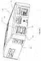
- FIG. 1 ashows a perspective view from the top looking down of the room sensor housing with its external and internal components.
- FIG. 1 bshows a perspective view from the bottom looking up of the room sensor housing with its external and internal components
- FIG. 2shows side view of top cover of housing with vent slots.
- FIG. 3shows another side view of top cover of housing with vent slots.
- FIG. 4shows a cross section view of the sensor channel of which the ambient air flows through to reach the temperature sensing element.
- enclosure 10comprises top cover 20 and base 30 .
- Printed circuit board 40is housed within enclosure 10 .
- Printed circuit board 40also comprises display panel 50 , connector header 60 for wiring to other devices in the building, phone jack 70 to connect to a field device (i.e., laptop) for immediate information, up to four tactile switches 75 and temperature sensor 90 .
- the active components of the printed circuit board 40generate nearly 1 watt of heat, therefore it is important to separate that heat from the temperature sensor 90 . Typically this is achieved through distance; the further away the temperature sensor 90 is from the internal heat of the printed circuit board 40 , the less affected the temperature reading will be from the internal heat given off by the printed circuit board 40 .
- Top cover 20comprises top thermally isolating wall 100 and base 30 comprises bottom thermally isolating wall 200 each molded into both the top cover 20 and base 30 respectively to prevent the convective heat transfer from the components of the printed circuit board 40 through the air to the temperature sensor 90 .
- the printed circuit board 40also includes a machined slot 80 that essentially locates the temperature sensor 90 on an island. The machined slot 80 forces the heat given off by the components of the printed circuit board 40 to flow around machined slot 80 which increases the distance that the heat must conduct along, thereby limiting the heat transferred to the sensor.
- top thermally isolating wall 100 and bottom thermally isolating wall 200touch both the top and bottom surfaces of the printed circuit board 40 so that the air surrounding the temperature sensor 90 is completely isolated from the air surrounding the rest of the printed circuit board 40 .
- the machined slot 80is just inside of this isolated space so there is no tolerance issue of having the top cover 20 , base 30 and machined slot 80 all having to meet at the exact same location. It should also be noted, that a wide assortment of temperature sensors 90 may be used in the present invention.
- FIGS. 2 and 3show venting slots 300 located around the top cover 30 .
- the venting slotscomprise inlet slots 400 and outlet slots 500 to allow ambient air to flow through enclosure 10 and across temperature sensor 90 .
- the sensor channel 600(shown in FIG. 4 ) includes the path of the ambient air entering the inlet slots 400 and exiting through the outlet slots 500 .
- the airmoves in and out of the sensor channel 600 by means of natural convection. Natural convection is the movement of air due to the temperature gradient caused by the internal components that generate heat. Hot air rises, therefore, the heat generated by the components causes an upward flow of air across the components and also up and along the wall of the room.
- the 45° degree angled top thermally isolating wall 100 and bottom thermally isolating wall 200direct the air to flow up and out the side of top cover 20 .
- the temperature sensor 90is completely isolated from the other internal components within the enclosure 10 , it is heavily vented to allow room ambient air to freely pass through the sensor channel.
- the 45° angle of the machined slot 80 and top and bottom thermally isolating walls 100 and 200respectively allow the room air to more easily flow through the sensor channel.
- the venting slots 300require a large enough cumulative opening to allow the naturally convective air to move freely in and out of the sensor channel 600 .
- FIG. 4shows a cross section view of the sensor channel 600 .
- sensor channel 600represents the path of air that enters through inlet slots 400 and then exits through outlet slots 500 flowing over temperature sensor 90 .
Landscapes
- Physics & Mathematics (AREA)
- General Physics & Mathematics (AREA)
- Measuring Temperature Or Quantity Of Heat (AREA)
- Air Conditioning Control Device (AREA)
- Fire-Detection Mechanisms (AREA)
Abstract
Description
Claims (14)
Priority Applications (8)
| Application Number | Priority Date | Filing Date | Title |
|---|---|---|---|
| US12/498,423US8197130B2 (en) | 2008-07-08 | 2009-07-07 | Method to accurately read temperature for a room sensor apparatus |
| MX2011000270AMX2011000270A (en) | 2008-07-08 | 2009-07-08 | Method and apparatus to accurately read ambient room temperature for a room sensor apparatus. |
| CN200980126453.6ACN102089637B (en) | 2008-07-08 | 2009-07-08 | Method and apparatus to accurately read ambient room temperature for a room sensor apparatus |
| CA2730080ACA2730080C (en) | 2008-07-08 | 2009-07-08 | Method and apparatus to accurately read ambient room temperature for a room sensor apparatus |
| BRPI0915539-2ABRPI0915539B1 (en) | 2008-07-08 | 2009-07-08 | TEMPERATURE SENSOR DEVICE FOR MEASURING ENVIRONMENT TEMPERATURE IN A ROOM, COMPARTMENT AND METHOD FOR ACCURATELY READING THE TEMPERATURE FOR AN ENVIRONMENT SENSOR APPARATUS |
| EP09790128.4AEP2318816B1 (en) | 2008-07-08 | 2009-07-08 | Method and apparatus to accurately read ambient room temperature for a room sensor apparatus |
| PCT/US2009/049864WO2010006003A1 (en) | 2008-07-08 | 2009-07-08 | Method and apparatus to accurately read ambient room temperature for a room sensor apparatus |
| KR1020117000375AKR101613328B1 (en) | 2008-07-08 | 2009-07-08 | Method and apparatus to accurately read ambient room temperature for a room sensor apparatus |
Applications Claiming Priority (2)
| Application Number | Priority Date | Filing Date | Title |
|---|---|---|---|
| US7888108P | 2008-07-08 | 2008-07-08 | |
| US12/498,423US8197130B2 (en) | 2008-07-08 | 2009-07-07 | Method to accurately read temperature for a room sensor apparatus |
Publications (2)
| Publication Number | Publication Date |
|---|---|
| US20100020849A1 US20100020849A1 (en) | 2010-01-28 |
| US8197130B2true US8197130B2 (en) | 2012-06-12 |
Family
ID=41137572
Family Applications (1)
| Application Number | Title | Priority Date | Filing Date |
|---|---|---|---|
| US12/498,423Active2030-10-29US8197130B2 (en) | 2008-07-08 | 2009-07-07 | Method to accurately read temperature for a room sensor apparatus |
Country Status (8)
| Country | Link |
|---|---|
| US (1) | US8197130B2 (en) |
| EP (1) | EP2318816B1 (en) |
| KR (1) | KR101613328B1 (en) |
| CN (1) | CN102089637B (en) |
| BR (1) | BRPI0915539B1 (en) |
| CA (1) | CA2730080C (en) |
| MX (1) | MX2011000270A (en) |
| WO (1) | WO2010006003A1 (en) |
Cited By (8)
| Publication number | Priority date | Publication date | Assignee | Title |
|---|---|---|---|---|
| US20140021884A1 (en)* | 2012-07-18 | 2014-01-23 | Dialight Corporation | High ambient temperature led luminaire with thermal compensation circuitry |
| US20140176161A1 (en)* | 2012-12-21 | 2014-06-26 | Murray W. Davis | Portable self powered line mountable device for measuring and transmitting relative humidity |
| US20170370607A1 (en)* | 2014-12-31 | 2017-12-28 | Gd Midea Air-Conditioning Equipment Co., Ltd. | Air conditioner |
| US20180198901A1 (en)* | 2017-01-06 | 2018-07-12 | Kyocera Corporation | Electronic device |
| US20190346162A1 (en)* | 2015-08-27 | 2019-11-14 | Delta T, Llc | Control with enhanced sensing capabilities and improved snap fit engagement |
| WO2022223637A1 (en) | 2021-04-22 | 2022-10-27 | Belimo Holding Ag | Room unit for an hvac system |
| WO2022223638A1 (en) | 2021-04-22 | 2022-10-27 | Belimo Holding Ag | Room unit for an hvac system |
| WO2023104980A1 (en) | 2021-12-08 | 2023-06-15 | Belimo Holding Ag | Determination of a temperature in a hvac system |
Families Citing this family (8)
| Publication number | Priority date | Publication date | Assignee | Title |
|---|---|---|---|---|
| EP2640175B1 (en)* | 2012-03-12 | 2017-07-12 | Siemens Aktiengesellschaft | Assembly for a modular automation device |
| EP2701478A1 (en)* | 2012-08-20 | 2014-02-26 | Siemens Aktiengesellschaft | Assembly for a modular automation device |
| US10288301B2 (en)* | 2015-04-08 | 2019-05-14 | Haier Us Appliance Solutions, Inc. | Thermostat hood for a heating system of an air conditioner unit |
| GB2540362B (en)* | 2015-07-13 | 2017-10-11 | British Gas Trading Ltd | Temperature sensor arrangement |
| JP6699243B2 (en)* | 2016-03-03 | 2020-05-27 | オムロン株式会社 | Sensor device |
| KR101883967B1 (en)* | 2016-11-23 | 2018-07-31 | 이진식 | Apparatus of gauging data |
| CN108106749A (en)* | 2017-11-24 | 2018-06-01 | 中国电子科技集团公司第十研究所 | A kind of temperature checking method and device |
| CN108061607A (en)* | 2017-11-30 | 2018-05-22 | 贵州航天电子科技有限公司 | A kind of small volume high precision temperature measurement module |
Citations (7)
| Publication number | Priority date | Publication date | Assignee | Title |
|---|---|---|---|---|
| US5008775A (en) | 1988-09-13 | 1991-04-16 | Honeywell Regelsysteme Gmbh | Sensor and control module with improved sensor isolation |
| US6032867A (en)* | 1998-04-21 | 2000-03-07 | Dushane; Steve | Flat plate thermostat and wall mounting method |
| US6082894A (en)* | 1996-08-30 | 2000-07-04 | Hubbell Incorporated | Temperature and passive infrared sensor module |
| US6293697B1 (en)* | 2000-01-18 | 2001-09-25 | Mamac Systems, Inc. | Housing for HVAC control unit |
| US6347747B1 (en)* | 1998-05-01 | 2002-02-19 | Intellinet, Inc. | Stand-alone thermostat |
| US20020080852A1 (en) | 2000-12-21 | 2002-06-27 | Mirov Russell N. | Method and apparatus for isolating an ambient air temperature sensor |
| US7900464B2 (en)* | 2006-09-15 | 2011-03-08 | Denso Corporation | Humidity detecting apparatus and vehicular air conditioner having the same |
- 2009
- 2009-07-07USUS12/498,423patent/US8197130B2/enactiveActive
- 2009-07-08BRBRPI0915539-2Apatent/BRPI0915539B1/enactiveIP Right Grant
- 2009-07-08CNCN200980126453.6Apatent/CN102089637B/enactiveActive
- 2009-07-08CACA2730080Apatent/CA2730080C/enactiveActive
- 2009-07-08MXMX2011000270Apatent/MX2011000270A/enactiveIP Right Grant
- 2009-07-08EPEP09790128.4Apatent/EP2318816B1/enactiveActive
- 2009-07-08KRKR1020117000375Apatent/KR101613328B1/enactiveActive
- 2009-07-08WOPCT/US2009/049864patent/WO2010006003A1/enactiveApplication Filing
Patent Citations (7)
| Publication number | Priority date | Publication date | Assignee | Title |
|---|---|---|---|---|
| US5008775A (en) | 1988-09-13 | 1991-04-16 | Honeywell Regelsysteme Gmbh | Sensor and control module with improved sensor isolation |
| US6082894A (en)* | 1996-08-30 | 2000-07-04 | Hubbell Incorporated | Temperature and passive infrared sensor module |
| US6032867A (en)* | 1998-04-21 | 2000-03-07 | Dushane; Steve | Flat plate thermostat and wall mounting method |
| US6347747B1 (en)* | 1998-05-01 | 2002-02-19 | Intellinet, Inc. | Stand-alone thermostat |
| US6293697B1 (en)* | 2000-01-18 | 2001-09-25 | Mamac Systems, Inc. | Housing for HVAC control unit |
| US20020080852A1 (en) | 2000-12-21 | 2002-06-27 | Mirov Russell N. | Method and apparatus for isolating an ambient air temperature sensor |
| US7900464B2 (en)* | 2006-09-15 | 2011-03-08 | Denso Corporation | Humidity detecting apparatus and vehicular air conditioner having the same |
Cited By (12)
| Publication number | Priority date | Publication date | Assignee | Title |
|---|---|---|---|---|
| US20140021884A1 (en)* | 2012-07-18 | 2014-01-23 | Dialight Corporation | High ambient temperature led luminaire with thermal compensation circuitry |
| US20140176161A1 (en)* | 2012-12-21 | 2014-06-26 | Murray W. Davis | Portable self powered line mountable device for measuring and transmitting relative humidity |
| US9241559B2 (en)* | 2012-12-21 | 2016-01-26 | Murray W. Davis | Portable self powered line mountable device for measuring and transmitting relative humidity |
| US9380857B2 (en) | 2012-12-21 | 2016-07-05 | Murray W. Davis | Portable self powered line mountable device for measuring and transmitting ambient temperature |
| US20170370607A1 (en)* | 2014-12-31 | 2017-12-28 | Gd Midea Air-Conditioning Equipment Co., Ltd. | Air conditioner |
| US10488073B2 (en)* | 2014-12-31 | 2019-11-26 | Gd Midea Air-Conditioning Equipment Co., Ltd. | Air conditioner |
| US20190346162A1 (en)* | 2015-08-27 | 2019-11-14 | Delta T, Llc | Control with enhanced sensing capabilities and improved snap fit engagement |
| US11408622B2 (en)* | 2015-08-27 | 2022-08-09 | Delta T, Llc | Control with enhanced sensing capabilities |
| US20180198901A1 (en)* | 2017-01-06 | 2018-07-12 | Kyocera Corporation | Electronic device |
| WO2022223637A1 (en) | 2021-04-22 | 2022-10-27 | Belimo Holding Ag | Room unit for an hvac system |
| WO2022223638A1 (en) | 2021-04-22 | 2022-10-27 | Belimo Holding Ag | Room unit for an hvac system |
| WO2023104980A1 (en) | 2021-12-08 | 2023-06-15 | Belimo Holding Ag | Determination of a temperature in a hvac system |
Also Published As
| Publication number | Publication date |
|---|---|
| CN102089637A (en) | 2011-06-08 |
| BRPI0915539B1 (en) | 2019-07-09 |
| MX2011000270A (en) | 2011-02-22 |
| WO2010006003A1 (en) | 2010-01-14 |
| KR101613328B1 (en) | 2016-04-18 |
| CA2730080A1 (en) | 2010-01-14 |
| CN102089637B (en) | 2013-07-17 |
| US20100020849A1 (en) | 2010-01-28 |
| EP2318816A1 (en) | 2011-05-11 |
| KR20110027762A (en) | 2011-03-16 |
| EP2318816B1 (en) | 2016-09-28 |
| BRPI0915539A2 (en) | 2016-01-26 |
| CA2730080C (en) | 2018-02-13 |
Similar Documents
| Publication | Publication Date | Title |
|---|---|---|
| US8197130B2 (en) | Method to accurately read temperature for a room sensor apparatus | |
| CA2451707C (en) | Multiple point averaging duct temperature sensor | |
| US7272945B2 (en) | Environmental condition measurement system | |
| US8366315B2 (en) | Open-loop vertical drywell gradient correction system and method | |
| US7395173B2 (en) | Temperature sensing device | |
| EP2564678B1 (en) | Airflow detector and method of measuring airflow | |
| JP7059836B2 (en) | Wind condition detector | |
| US20210063253A1 (en) | Flow guiding and heat dissipating type dry block temperature calibrator | |
| CN108073199A (en) | Temperature measuring apparatus, check device and control method | |
| JP2010107218A (en) | Method and device for measuring humidity distribution, and environment testing device | |
| KR200478963Y1 (en) | Temperature sensor | |
| CN115144084B (en) | Temperature measuring device | |
| US20140260597A1 (en) | Gas flow measurement system and method of operation | |
| CN100480589C (en) | Radiator | |
| CN107300571B (en) | Building wall heat transfer coefficient detection device and building wall heat transfer coefficient detection method | |
| JP4965319B2 (en) | measuring device | |
| US20070171086A1 (en) | Environmental monitor | |
| JP7609679B2 (en) | Temperature Measuring Device | |
| WO2009139765A1 (en) | Sensor assembly with optimized response time | |
| JP2012216395A (en) | Terminal block and power distribution device using the same | |
| JPH0220652Y2 (en) | ||
| EP3521768A1 (en) | Sensor module and package | |
| JP2022167459A (en) | temperature sensor | |
| JP2003315157A (en) | Skin load measuring method | |
| JP2012216394A (en) | Terminal block and power distribution device using the same |
Legal Events
| Date | Code | Title | Description |
|---|---|---|---|
| AS | Assignment | Owner name:SIEMENS BUILDING TECHNOLOGIES, INC., ILLINOIS Free format text:ASSIGNMENT OF ASSIGNORS INTEREST;ASSIGNOR:WILLE, JAMES P.;REEL/FRAME:022919/0755 Effective date:20080916 | |
| AS | Assignment | Owner name:SIEMENS INDUSTRY, INC.,GEORGIA Free format text:MERGER;ASSIGNOR:SIEMENS BUILDING TECHNOLOGIES, INC.;REEL/FRAME:024054/0938 Effective date:20090923 Owner name:SIEMENS INDUSTRY, INC., GEORGIA Free format text:MERGER;ASSIGNOR:SIEMENS BUILDING TECHNOLOGIES, INC.;REEL/FRAME:024054/0938 Effective date:20090923 | |
| STCF | Information on status: patent grant | Free format text:PATENTED CASE | |
| FPAY | Fee payment | Year of fee payment:4 | |
| MAFP | Maintenance fee payment | Free format text:PAYMENT OF MAINTENANCE FEE, 8TH YEAR, LARGE ENTITY (ORIGINAL EVENT CODE: M1552); ENTITY STATUS OF PATENT OWNER: LARGE ENTITY Year of fee payment:8 | |
| MAFP | Maintenance fee payment | Free format text:PAYMENT OF MAINTENANCE FEE, 12TH YEAR, LARGE ENTITY (ORIGINAL EVENT CODE: M1553); ENTITY STATUS OF PATENT OWNER: LARGE ENTITY Year of fee payment:12 |