US8196661B2 - Method for providing a preferential specific injection distribution from a horizontal injection well - Google Patents
Method for providing a preferential specific injection distribution from a horizontal injection wellDownload PDFInfo
- Publication number
- US8196661B2 US8196661B2US12/525,055US52505508AUS8196661B2US 8196661 B2US8196661 B2US 8196661B2US 52505508 AUS52505508 AUS 52505508AUS 8196661 B2US8196661 B2US 8196661B2
- Authority
- US
- United States
- Prior art keywords
- annulus
- formation
- well bore
- tubing string
- tubing
- Prior art date
- Legal status (The legal status is an assumption and is not a legal conclusion. Google has not performed a legal analysis and makes no representation as to the accuracy of the status listed.)
- Expired - Fee Related, expires
Links
Images


Classifications
- E—FIXED CONSTRUCTIONS
- E21—EARTH OR ROCK DRILLING; MINING
- E21B—EARTH OR ROCK DRILLING; OBTAINING OIL, GAS, WATER, SOLUBLE OR MELTABLE MATERIALS OR A SLURRY OF MINERALS FROM WELLS
- E21B43/00—Methods or apparatus for obtaining oil, gas, water, soluble or meltable materials or a slurry of minerals from wells
- E21B43/16—Enhanced recovery methods for obtaining hydrocarbons
- E21B43/24—Enhanced recovery methods for obtaining hydrocarbons using heat, e.g. steam injection
- E—FIXED CONSTRUCTIONS
- E21—EARTH OR ROCK DRILLING; MINING
- E21B—EARTH OR ROCK DRILLING; OBTAINING OIL, GAS, WATER, SOLUBLE OR MELTABLE MATERIALS OR A SLURRY OF MINERALS FROM WELLS
- E21B43/00—Methods or apparatus for obtaining oil, gas, water, soluble or meltable materials or a slurry of minerals from wells
- E21B43/30—Specific pattern of wells, e.g. optimising the spacing of wells
- E21B43/305—Specific pattern of wells, e.g. optimising the spacing of wells comprising at least one inclined or horizontal well
Definitions
- the present methodis directed towards the improved recovery of hydrocarbons from subterranean formations. More specifically the present method relates to a method of providing a preferential injection distribution in to a permeable formation from a horizontal well bore.
- SAGDsteam assisted gravity drainage
- the steamcondenses, it transfers energy to the bitumen, which improves its mobility by heating it up and decreasing its viscosity.
- the mobile bitumen and condensed waterflows down the edges of the steam chamber and into the producer wellbore. The fluid mixture that enters the producer well is then produced to surface.
- One strategy used for preferred injection distribution of steamis to use a slotted liner with a low open area.
- the active mechanism for providing the improved injection fluid distributionis an increased radial flow resistance due to near well bore divergence losses.
- Another strategyis to use a technique called “limited entry”. This technique involves injecting steam into a tubing string which is inside the substantially perforated liner of an injection well.
- the tubing stringis equipped with a limited number of distributed perforations.
- the active mechanism in this strategyis utilization of the choked-flow phenomenon which limits mass-flow velocity through a restriction to sonic velocity.
- a method for distributing injection fluid in a horizontal well bore in fluid communication with hydrocarbon bearing formationcomprises determining flow resistance characteristics of the formation along at least a portion of the length of the horizontal well bore.
- An injection tubing string having a sidewall defining a tubing boreis injected into the horizontal well bore.
- An annulusis defined between the horizontal well bore and the tubing string, the tubing string being provided with ports having a selected distribution and geometry communicating fluid between the tubing bore and the annulus.
- the annulus geometryis selectively controlled along the length of the tubing string through at least one of axial distribution of eccentricity and flow area of the annulus, so as to provide selected flow restriction characteristics along the annulus, such that when injection fluid is pumped into the tubing, a resulting flow resistance network is formed by the tubing bore, the ports, the annulus and the formation, resulting in a desired distribution of the fluid into the formation.
- a preferential injection distribution of steam and heat from a horizontal well bore into a subterranean formationis provided. Initially, a horizontally oriented well is drilled into the formation. Next an apparatus according to the present invention is installed in the well bore. Steam is then supplied to the apparatus such that it provides a preferential distribution to the subterranean formation.
- the preferential distribution of steammay be uniform or it may be directed to the preferential recovery of hydrocarbons by targeting injection to areas of specific formation permeability or depletion history.
- a first stepincludes determining the preferential distribution of injected fluid along the length of the horizontally positioned wellbore.
- a second stepincludes configuring the injection apparatus to deliver the preferential distribution of injection fluid by determining the appropriate sizing and spacing of injection openings, and the required annular gap.
- the apparatusconsists of a sand control device and a smaller diameter tubular with a plurality of preferentially distributed injection openings positioned within the sand control device for the purpose of distributing fluid within the sand control device.
- a third stepincludes positioning the apparatus in a horizontal well bore.
- a fourth stepincludes supplying steam to the apparatus for preferential distribution to the well bore.
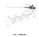
- FIG. 1is a schematic cross-section of a horizontal well bore completed in accordance with the prior art.
- FIG. 2is a schematic cross-section of a horizontal well bore completed in accordance with the prior art.
- FIG. 3is a schematic cross-section of a horizontal well bore completed in accordance with the present method.
- FIG. 4is an end view in section of a tubing string supported by a centralizer.
- FIG. 5is a graph showing the pressure increase expected as the flow ratio is improved.
- FIG. 6is a graph showing the non-linear flow-rate pressure loss relationship for a given fluid through a sample injection opening.
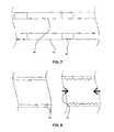
- FIG. 7is a schematic showing a cross-section of a small portion of a completed horizontal well bore wherein the tubing is equipped with discrete annular flow restriction fixturing.
- FIG. 8is a schematic showing cross-sections of a small portion of a completed horizontal well bore wherein the tubing is provided with corrugations.
- FIG. 9is a graph which demonstrates the effect of axial annular flow resistance on specific injection rate.
- FIG. 10is a graph which demonstrates the benefit of preferential distribution of tubing injection openings where variable formation permeability exists.
- Horizontal injection wellsare most effective if the volume of injected steam is preferentially distributed along the length of the horizontal well which allows for creation of a uniform steam chamber along the length of the injector. In some cases the preferential distribution is uniform along the length of the well and in other cases the preferential distribution targets specific sections of the reservoir which are less depleted than other sections.
- the method described belowmay be used provide a preferential distribution of steam to a subterranean formation via a substantially horizontally positioned wellbore based on an assessment of the formation characteristics (such as permeability distribution, flow resistance in the formation, and depletion history), and to minimize injection pressures.
- FIG. 1a prior art steam distribution method is shown. Steam is distributed to the formation 10 through a limited number of slotted perforations 18 in the liner 22 .
- the active mechanism for providing the injection fluid distributionis an increased radial flow resistance due to near well bore divergence losses.
- the linerhas a limited number of slotted perforations that are exposed to the formation.
- slotted perforations exposed to formations consisting of unconsolidated sandsare prone to plugging. Where the number of slotted perforations is low, such plugging may limit the injectivity of the well and may have an unfavourable impact on the steam distribution.
- an alternate strategyis required with more resistance to plugging.
- FIG. 2another prior art steam distribution method is shown.
- a horizontal wellbore 14is shown penetrating a hydrocarbon bearing formation 12 .
- Steamis injected into the wellbore through the tubing string 22 and flows to the horizontal section of the wellbore where it exits the tubing string through perforations 18 in the tubing.
- the steam injection rate, perforation geometry and perforation quantityare selected such that critical flow will be achieved through the tubing perforations, provided the steam is supplied with sufficient injection pressure such that a critical pressure ratio is achieved between the injection tubing and the annulus.
- This injection strategyprovides uniform steam distribution to the annulus between the liner and the tubing with a large pressure drop between the tubing and the annulus.
- a steam injection strategywould provide an injection distribution tailored to the condition of the formation (such as the depletion of the well, or the flow resistance network) with minimum pressure drop.
- the “flow resistance” of a formationis related to the ability of a formation to receive fluids injected from the well bore under the action of a pressure differential between the wellbore and the formation pore pressure, and is dependent upon formation properties such as permeability, and any other factors that may contribute to the amount of fluid that can be injected.
- a preferential injection distribution of steam and heat into a permeable subterranean formation from a horizontal well borehas a heel portion 14 and a toe portion 16 .
- the distribution of formation permeability and depletion historyis determined along the length, or a target length, of the horizontally positioned wellbore. Using this information, a preferred injection distribution may then be determined.
- the injection apparatuscan then be configured to deliver the preferred injection distribution by providing selected flow restriction characteristics. This is done by determining the appropriate geometry and spacing of injection openings, and the required annular geometry.
- the flow resistances introduced by these variablescreate a flow resistance network in combination with the flow resistance of the formation to achieve the preferred injection distribution.
- the apparatusconsists of a sand control device 28 , which is preferentially a slotted liner, and a smaller diameter tubing string 22 with a plurality of preferentially distributed injection ports 18 .
- the ports 18are distributed non-uniformly to achieve the desired injection distribution.
- the size of the perforations 18may be adjusted along with, or instead of, the perforation density to help achieve the desired injection distribution.
- the sand control device 28if used, is positioned in the horizontal well bore.
- Sand control device 28may be a slotted liner, a wire-wrap screen, or other design that provides similar results.
- Injection tubing 22is then inserted.
- the well bore 12may not require a liner 28 , in which case tubing string 22 may be inserted directly into well bore 12 .
- Injection tubing 22has an injection zone with a plurality of preferentially distributed injection openings 18 or perforations, and an outside diameter such that the size of the offset annulus 30 provides preferential redistribution of flow within the annulus.
- tubing 22will tend to rest on the lower inside surface of the sand control device 28 or well bore 12 , so that annulus 30 will be larger on the top than on the bottom.
- the tubing 22is installed such that the perforations 18 align with the injection target area of the well. However, the tubing 22 is preferably the full length of the well with a capped end.
- steamis injected along the horizontal well bore 12 through the injection tubing 22 .
- the fluid injectionis initiated at surface through the tubing 22 , then through the injection openings 18 into the annulus 24 and then into the formation through the sand control device 28 .
- Horizontal injection wellsare generally more effective if the injection volume is distributed along the length of the horizontal well.
- the radial flow resistancemust be balanced with the axial flow resistance in the well. In the case of a tubing conveyed steam distribution apparatus, multiple radial and multiple axial flow resistances must be considered.
- the flow resistance networkmay be manipulated to provide desired results by controlling certain variables. These variables include: the geometry of the tubing string including the shape and diameter; the geometry, density and position of ports 18 ; the geometry of the annulus including the size of the annulus, the eccentric position of tubing string 22 within bore 12 , and restriction points within the annulus; and the presence or absence of a liner 28 , including the geometry and permeability of the liner 28 . This list is not intended to be exhaustive, and once the principles discussed herein are understood, other variables may be apparent to those skilled in the art. The details of these factors are discussed below.
- the distribution of flow from the tubular string into the annulusis controlled primarily by the through-wall flow resistance provided by the injection openings on the removable tubular string, the axial variation in pressure along the injection tubing 22 , and the pressure differential between the injection tubing 22 and the annulus.
- the number and geometry of injection openings 18imposes a significant restriction to flow and the cross-sectional area of the removable tubing string is adequate, the pressure distribution in the tubular annulus will be substantially more uniform than the distribution within the removable tubular string.
- the radial flow resistance of the tubing string and the associated improvement in injection fluid distributionmust be balanced with the incremental pressure required to supply the desired flow rate through increased total flow resistance.
- non-linearitymay be used to promote rate-independence of the injection distribution, whereby large changes in the total injection rate have minimal impact on the distribution of fluid. Furthermore this can be done without plugging injection openings, because the active distribution injection openings are not exposed to formation material.
- injection distribution into the reservoiris further influenced by the size of the annular space between the inner and outer tubulars, or the tubular string 22 and the sand control device 28 , respectively.
- a small annular spacemay be selected to cause the injection distribution to be more independent of reservoir permeability or a larger annular space may be utilized to encourage injection into more permeable regions.
- the cross-sectional flow area of the annulus, or the geometry of the annuluscan be controlled by appropriately selecting the internal diameter of the sand control device 28 and the external diameter of the tubing string 22 such that they provide the desired flow area.
- the geometry of the annulusrefers to the “annular gap”, or the cross-sectional flow area between the well bore 12 or liner 28 , and the tubing string 22 , and need not be consistent along the entire length of the annulus.
- the geometry of the annular spacecontrols the annular axial flow resistance which controls the tendency of fluid to redistribute along the length of the annulus and into the reservoir.
- Various meansmay be provided to selectively control the annulus flow area. Examples of these include selection of the inside diameter of well bore 12 or liner 28 along the horizontal well length. Where no liner is used, in so called barefoot completions, selection of bit size combined with selectively under reaming may be used to control bore hole diameter, as is known in the art. Where liner 28 is used, the liner tubular inside diameter may be selected to provide a constant inside diameter or may be selected to provide intervals of differing diameter. Further means to control annulus flow area may be obtained by providing tubular fixturing 84 at intervals along the tubing string 84 , as shown in FIG. 7 .
- Tubular fixturing 84may be provided in the form of inflatable packers or sleeves attached to the tubular to effectively increase its outside diameter over an interval. It will be apparent that the means used to control the well bore diameter and means used to control the tubing or tubing fixturing outside diameter can be used in combination to provide considerable flexibility in selection of annular area when the tubing string is placed in the well bore and thus controls the annular axial flow resistance which controls the tendency of fluid to redistribute along the length of the annulus and into the reservoir. Once the injection fluid has been distributed preferentially throughout the annular space it can flow radially into the formation or it can further distribute itself throughout the annulus depending on the flow resistance of the formation.
- a further means to selectively control annular flow areamay be obtained by providing corrugations 90 in the tubing wall.
- the corrugationscan be made to expand radially providing a means to selectively reduce the annulus flow area while the string is disposed in the well bore. It will be apparent that the application of axial tension load provides a means to increase the annulus flow area.
- FIG. 9shows two sample flow distributions in a reservoir with variable permeability along its length.
- the centre sectionis five times less permeable than the end sections of the formation 54 .
- the specific injection rateis compared for two different axial annular flow resistances.
- the curve 52represents a low annular flow resistance and curve 50 represents a substantially larger annular flow resistance. It is clear from this comparison that by controlling the annular flow resistance, the injection fluid distribution can also be controlled.
- An example of a situation where it would be desirable to change the geometry of the annulus by restricting certain points, such as by using tubular fixturing to provide an increase in the axial annular flow resistance at discrete points along the length of the well boreis where certain portions of the formation are to be targeted, or certain portions are to be avoided.
- certain portions of the formationare to be targeted, or certain portions are to be avoided.
- the formationhas previously been completed, but the injected fluid was not preferentially distributed, there may be some portions of the formation that it would be beneficial to inject steam into.
- Other such situationswill be apparent to those skilled in the art.
- Slotted tubing perforationsprovide the preferred geometry for tubing perforations as they are the least sensitive to the proximity of the inside diameter of the sand control device 28 .
- the injection tubingmay be resting on the bottom surface of the inside diameter of the sand control device 28 thus restricting injection through perforations aligned with or nearly aligned with the bottom of the injection tubing.
- the relatively large perimeter to flow area ratio of the slotted perforationdecreases the flow restriction caused by the proximity of the inner diameter of the sand control device 28 . This allows more accurate prediction of flow characteristics and thus more accurate distribution of steam.
- slotted tubing perforationsprovide the preferred injection opening geometry because they can be produced economically in a range of quantities and distributions to provide the radial flow control required.
- Another advantage of this methodis that the preferentially distributed injection openings are located on a retrievable tubing string and as such the tubing string may be cleaned, replaced, modified, or re-positioned at any point in the well life. Similarly, existing injection wells may be re-completed with such an injection string to improve overall injection performance, or to direct injected fluid to regions of the reservoir that were not reached with the original completion strategy. In these situations an understanding of the well history, the permeability distribution and the preferred injection distribution will allow optimal recompletion.
- the well spacing in SAGD operationsmay be taken into account. In locations where injector and producer wells were closer together, pressure variations along the injection well may be desirable to prevent steam breakthrough to the production well.
- Another factorincludes the evolution of steam chamber/preferential steam chamber growth. If through field measurements, taken using, for example, tiltmeter, microseismic, etc., steam chamber growth is determined not to be ideal, the well can be recompleted with adjusted steam distribution.
- the preferred distribution of injection fluid in horizontal well boresis uniform. It has been discussed in the prior art that to achieve uniform distribution, the radial flow resistance for the injection fluid must be increased relative to the axial flow resistance. The trade-off to increasing radial flow resistance is that the injection pressure must be increased in order to supply the equivalent amount of injection fluid to the reservoir. Increasing injection pressure places higher temperature and pressure demands on the fluid injection apparatus.
- FIG. 5illustrates the pressure trade-off for a single sample well configuration with a uniform spacing of tubing perforations by comparing the injection pressure (the difference between pressure at the heel of the tubing and the pressure in the reservoir) with the “injection flow ratio”, defined as the ratio of maximum to minimum specific injection rate into the reservoir for a sample completion configuration (injection flow ratio). With reference to FIG. 5 the relationship shown is asymptotic to an injection flow ratio of one. This relationship could be further optimized by improved distribution of injection perforations.
- the preferred injection pressureis a balance between providing a preferential flow distribution and maintaining mechanical and economic feasibility.
- the preferred distribution of injection fluidwill not be uniform. This may be the case in a situation with variable formation permeability as previously described, wherein the central formation region has permeability five times lower than outer regions. If more fluid injection into the low permeability zone is required, the perforations may be preferentially distributed along the central portion of the well bore.
- FIG. 10An example of the resulting injection distributions is shown in FIG. 10 .
- the curve 60shows the specific injection rate in the case where the injection openings are distributed only in the low permeability (center) section of the well and there is high axial annular flow resistance, compared to the base case 62 with substantially evenly distributed injection openings and low axial annular flow resistance. It is clear from FIG.
- flow distributioncan be controlled by varying the distribution of the injection openings on the tubing string. Additionally, a non-uniform distribution may be useful in situations where the reservoir has previously been depleted in a non-uniform manner and the injection distribution will target less depleted sections of the reservoir.
- the flow rate exiting the perforations in the tubingmay have high enough velocity that it creates a risk of damage to the inside surface of the sand control device 28 due to impingement.
- the preferred method of preventing impingementis to use rigid fixed centralizers 32 on the tubing 22 .
- the centralizerswould be located at positions corresponding to the perforations 18 in the tubing 22 and would prevent direct impingement of steam onto the sand control device 28 and still allow flow between the tubing 22 and annulus 30 .
- One of the advantages of the method and apparatus described aboveis that it can be used to provide a preferential injection distribution into a subterranean formation where the injection distribution is largely independent of local variations in formation permeability. Another advantage is that it can be used to provide a preferential injection distribution into a subterranean formation where the preferential injection distribution is not uniform.
Landscapes
- Life Sciences & Earth Sciences (AREA)
- Engineering & Computer Science (AREA)
- Geology (AREA)
- Mining & Mineral Resources (AREA)
- Physics & Mathematics (AREA)
- Environmental & Geological Engineering (AREA)
- Fluid Mechanics (AREA)
- General Life Sciences & Earth Sciences (AREA)
- Geochemistry & Mineralogy (AREA)
- Consolidation Of Soil By Introduction Of Solidifying Substances Into Soil (AREA)
- Pipe Accessories (AREA)
Abstract
Description
Claims (18)
Priority Applications (1)
| Application Number | Priority Date | Filing Date | Title |
|---|---|---|---|
| US12/525,055US8196661B2 (en) | 2007-01-29 | 2008-01-29 | Method for providing a preferential specific injection distribution from a horizontal injection well |
Applications Claiming Priority (3)
| Application Number | Priority Date | Filing Date | Title |
|---|---|---|---|
| US88713307P | 2007-01-29 | 2007-01-29 | |
| US12/525,055US8196661B2 (en) | 2007-01-29 | 2008-01-29 | Method for providing a preferential specific injection distribution from a horizontal injection well |
| PCT/CA2008/000135WO2008092241A1 (en) | 2007-01-29 | 2008-01-29 | A method for providing a preferential specific injection distribution from a horizontal injection well |
Publications (2)
| Publication Number | Publication Date |
|---|---|
| US20100126720A1 US20100126720A1 (en) | 2010-05-27 |
| US8196661B2true US8196661B2 (en) | 2012-06-12 |
Family
ID=39673594
Family Applications (1)
| Application Number | Title | Priority Date | Filing Date |
|---|---|---|---|
| US12/525,055Expired - Fee RelatedUS8196661B2 (en) | 2007-01-29 | 2008-01-29 | Method for providing a preferential specific injection distribution from a horizontal injection well |
Country Status (3)
| Country | Link |
|---|---|
| US (1) | US8196661B2 (en) |
| CA (1) | CA2676679C (en) |
| WO (1) | WO2008092241A1 (en) |
Cited By (1)
| Publication number | Priority date | Publication date | Assignee | Title |
|---|---|---|---|---|
| US9664022B2 (en) | 2013-12-17 | 2017-05-30 | Cenovus Energy Inc. | Convective SAGD process |
Families Citing this family (14)
| Publication number | Priority date | Publication date | Assignee | Title |
|---|---|---|---|---|
| US7913755B2 (en) | 2007-10-19 | 2011-03-29 | Baker Hughes Incorporated | Device and system for well completion and control and method for completing and controlling a well |
| US8113292B2 (en) | 2008-05-13 | 2012-02-14 | Baker Hughes Incorporated | Strokable liner hanger and method |
| US8555958B2 (en) | 2008-05-13 | 2013-10-15 | Baker Hughes Incorporated | Pipeless steam assisted gravity drainage system and method |
| US8171999B2 (en) | 2008-05-13 | 2012-05-08 | Baker Huges Incorporated | Downhole flow control device and method |
| US9303493B2 (en) | 2009-05-15 | 2016-04-05 | Vast Power Portfolio, Llc | Method and apparatus for strain relief in thermal liners for fluid transfer |
| US8132624B2 (en) | 2009-06-02 | 2012-03-13 | Baker Hughes Incorporated | Permeability flow balancing within integral screen joints and method |
| US8056627B2 (en)* | 2009-06-02 | 2011-11-15 | Baker Hughes Incorporated | Permeability flow balancing within integral screen joints and method |
| US20100300674A1 (en)* | 2009-06-02 | 2010-12-02 | Baker Hughes Incorporated | Permeability flow balancing within integral screen joints |
| US8151881B2 (en) | 2009-06-02 | 2012-04-10 | Baker Hughes Incorporated | Permeability flow balancing within integral screen joints |
| RU2012154307A (en) | 2010-05-17 | 2014-06-27 | Васт Пауэр Портфоулиоу, Ллк | BENDING TAIL WITH COMPENSATION OF DEFORMATION FOR FILTRATION OF FLUIDS, METHOD AND DEVICE |
| NO338616B1 (en)* | 2010-08-04 | 2016-09-12 | Statoil Petroleum As | Apparatus and method for storing carbon dioxide in underground geological formations |
| CN103092139B (en)* | 2011-11-01 | 2017-02-22 | 中国石油化工股份有限公司 | Horizontal well steam flooding three-dimensional physical simulation measuring and control device |
| WO2016140664A1 (en)* | 2015-03-04 | 2016-09-09 | Halliburton Energy Services, Inc. | Steam operated injection and production device |
| CN111946314B (en)* | 2019-05-15 | 2022-12-02 | 中国石油天然气股份有限公司 | Injection and extraction control pipe column for thickened oil horizontal well |
Citations (52)
| Publication number | Priority date | Publication date | Assignee | Title |
|---|---|---|---|---|
| US4081028A (en) | 1977-04-04 | 1978-03-28 | Chevron Research Company | Steam distribution system for use in a well |
| US4099563A (en) | 1977-03-31 | 1978-07-11 | Chevron Research Company | Steam injection system for use in a well |
| US4399865A (en) | 1981-07-20 | 1983-08-23 | Chevron Research Company | Concentric steaming string downhole apparatus |
| US4410216A (en) | 1979-12-31 | 1983-10-18 | Heavy Oil Process, Inc. | Method for recovering high viscosity oils |
| US4577691A (en) | 1984-09-10 | 1986-03-25 | Texaco Inc. | Method and apparatus for producing viscous hydrocarbons from a subterranean formation |
| US4595057A (en) | 1984-05-18 | 1986-06-17 | Chevron Research Company | Parallel string method for multiple string, thermal fluid injection |
| US4640355A (en) | 1985-03-26 | 1987-02-03 | Chevron Research Company | Limited entry method for multiple zone, compressible fluid injection |
| US4646828A (en) | 1985-11-01 | 1987-03-03 | Otis Engineering Corporation | Apparatus for enhanced oil recovery |
| US4648455A (en) | 1986-04-16 | 1987-03-10 | Baker Oil Tools, Inc. | Method and apparatus for steam injection in subterranean wells |
| US4673039A (en) | 1986-01-24 | 1987-06-16 | Mohaupt Henry H | Well completion technique |
| US4711304A (en) | 1986-12-15 | 1987-12-08 | Camco, Incorporated | Method of and apparatus for injection of steam into multiple well zones |
| US4770244A (en) | 1986-06-24 | 1988-09-13 | Chevron Research Company | Downhole fixed choke for steam injection |
| US4921044A (en) | 1987-03-09 | 1990-05-01 | Otis Engineering Corporation | Well injection systems |
| US5014787A (en) | 1989-08-16 | 1991-05-14 | Chevron Research Company | Single well injection and production system |
| US5024274A (en) | 1985-11-01 | 1991-06-18 | Otis Engineering Corp. | Method and apparatus for enhanced oil recovery |
| CA2054818A1 (en) | 1990-11-02 | 1992-05-03 | Claude Gadelle | Method for facilitating fluid injection in a producing well |
| CA2054780A1 (en) | 1990-11-02 | 1992-05-03 | Claude Gadelle | Methode for stimulating effluent production in a pay zone |
| CA2058108A1 (en) | 1990-12-21 | 1992-06-22 | John H. Duerksen | Single well injection and production system |
| CA1303972C (en) | 1986-11-12 | 1992-06-23 | Mobil Oil Corporation | Limited entry, multiple fracturing from deviated wellbores |
| US5123485A (en) | 1989-12-08 | 1992-06-23 | Chevron Research And Technology Company | Method of flowing viscous hydrocarbons in a single well injection/production system |
| US5141054A (en) | 1991-03-13 | 1992-08-25 | Mobil Oil Corporation | Limited entry steam heating method for uniform heat distribution |
| WO1993025800A1 (en) | 1992-06-09 | 1993-12-23 | Shell Internationale Research Maatschappij B.V. | Method of completing an uncased section of a borehole |
| US5464059A (en) | 1993-03-26 | 1995-11-07 | Den Norske Stats Oljeselskap A.S. | Apparatus and method for supplying fluid into different zones in a formation |
| US5607018A (en) | 1991-04-01 | 1997-03-04 | Schuh; Frank J. | Viscid oil well completion |
| US5803178A (en) | 1996-09-13 | 1998-09-08 | Union Oil Company Of California | Downwell isolator |
| US5826655A (en) | 1996-04-25 | 1998-10-27 | Texaco Inc | Method for enhanced recovery of viscous oil deposits |
| US5896928A (en) | 1996-07-01 | 1999-04-27 | Baker Hughes Incorporated | Flow restriction device for use in producing wells |
| CA2219513A1 (en) | 1997-11-18 | 1999-05-18 | Russell Bacon | Steam distribution and production of hydrocarbons in a horizontal well |
| US5924475A (en) | 1997-05-05 | 1999-07-20 | Ford Global Technologies, Inc. | Method of making gas curable resin-coated sand cores |
| CA2254244A1 (en) | 1998-04-21 | 1999-10-21 | Texaco Development Corporation | Apparatus for enhanced recovery of viscous oil deposits |
| US6112817A (en) | 1997-05-06 | 2000-09-05 | Baker Hughes Incorporated | Flow control apparatus and methods |
| US6202748B1 (en) | 1999-04-15 | 2001-03-20 | Weatherford International, Inc. | Multi-stage maintenance device for subterranean well tool |
| US6237683B1 (en) | 1996-04-26 | 2001-05-29 | Camco International Inc. | Wellbore flow control device |
| CA2292278A1 (en) | 1999-12-10 | 2001-06-10 | Laurie Venning | A method of achieving a preferential flow distribution in a horizontal well bore |
| US6253853B1 (en) | 1998-10-05 | 2001-07-03 | Stellarton Energy Corporation | Fluid injection tubing assembly and method |
| US6260622B1 (en) | 1997-12-24 | 2001-07-17 | Shell Oil Company | Apparatus and method of injecting treatment fluids into a formation surrounding an underground borehole |
| US6371210B1 (en) | 2000-10-10 | 2002-04-16 | Weatherford/Lamb, Inc. | Flow control apparatus for use in a wellbore |
| US6457533B1 (en) | 1997-07-12 | 2002-10-01 | Weatherford/Lamb, Inc. | Downhole tubing |
| US20030062170A1 (en) | 2001-09-28 | 2003-04-03 | Noetic Engineering Inc. | Slotting geometry for metal pipe and method of use of the same |
| US6543538B2 (en) | 2000-07-18 | 2003-04-08 | Exxonmobil Upstream Research Company | Method for treating multiple wellbore intervals |
| US6619397B2 (en) | 1998-11-03 | 2003-09-16 | Baker Hughes Incorporated | Unconsolidated zonal isolation and control |
| US6622794B2 (en) | 2001-01-26 | 2003-09-23 | Baker Hughes Incorporated | Sand screen with active flow control and associated method of use |
| US6644412B2 (en) | 2001-04-25 | 2003-11-11 | Weatherford/Lamb, Inc. | Flow control apparatus for use in a wellbore |
| US6708763B2 (en) | 2002-03-13 | 2004-03-23 | Weatherford/Lamb, Inc. | Method and apparatus for injecting steam into a geological formation |
| US20040065445A1 (en) | 2001-05-15 | 2004-04-08 | Abercrombie Simpson Neil Andrew | Expanding tubing |
| CA2418195A1 (en) | 2003-01-31 | 2004-07-31 | Noetic Engineering Inc. | Method of steam injection through a horizontal well bore to stimulate oil well production |
| US6907936B2 (en)* | 2001-11-19 | 2005-06-21 | Packers Plus Energy Services Inc. | Method and apparatus for wellbore fluid treatment |
| US7032675B2 (en) | 2003-10-06 | 2006-04-25 | Halliburton Energy Services, Inc. | Thermally-controlled valves and methods of using the same in a wellbore |
| US7032665B1 (en)* | 2001-11-21 | 2006-04-25 | Berrier Mark L | System and method for gravel packaging a well |
| US7124830B2 (en) | 1997-11-01 | 2006-10-24 | Weatherford/Lamb, Inc. | Methods of placing expandable downhole tubing in a wellbore |
| US20070012454A1 (en) | 2005-07-18 | 2007-01-18 | Schlumberger Technology Corporation | Flow Control Valve For Injection Systems |
| US20080251255A1 (en) | 2007-04-11 | 2008-10-16 | Schlumberger Technology Corporation | Steam injection apparatus for steam assisted gravity drainage techniques |
- 2008
- 2008-01-29WOPCT/CA2008/000135patent/WO2008092241A1/enactiveApplication Filing
- 2008-01-29CACA2676679Apatent/CA2676679C/enactiveActive
- 2008-01-29USUS12/525,055patent/US8196661B2/ennot_activeExpired - Fee Related
Patent Citations (61)
| Publication number | Priority date | Publication date | Assignee | Title |
|---|---|---|---|---|
| US4099563A (en) | 1977-03-31 | 1978-07-11 | Chevron Research Company | Steam injection system for use in a well |
| US4081028A (en) | 1977-04-04 | 1978-03-28 | Chevron Research Company | Steam distribution system for use in a well |
| US4410216A (en) | 1979-12-31 | 1983-10-18 | Heavy Oil Process, Inc. | Method for recovering high viscosity oils |
| US4399865A (en) | 1981-07-20 | 1983-08-23 | Chevron Research Company | Concentric steaming string downhole apparatus |
| US4595057A (en) | 1984-05-18 | 1986-06-17 | Chevron Research Company | Parallel string method for multiple string, thermal fluid injection |
| CA1225020A (en) | 1984-05-18 | 1987-08-04 | John R. Deming | Parallel string method for multiple string, thermal fluid injection |
| US4577691A (en) | 1984-09-10 | 1986-03-25 | Texaco Inc. | Method and apparatus for producing viscous hydrocarbons from a subterranean formation |
| US4640355A (en) | 1985-03-26 | 1987-02-03 | Chevron Research Company | Limited entry method for multiple zone, compressible fluid injection |
| US4646828A (en) | 1985-11-01 | 1987-03-03 | Otis Engineering Corporation | Apparatus for enhanced oil recovery |
| US5024274A (en) | 1985-11-01 | 1991-06-18 | Otis Engineering Corp. | Method and apparatus for enhanced oil recovery |
| US4673039A (en) | 1986-01-24 | 1987-06-16 | Mohaupt Henry H | Well completion technique |
| US4648455A (en) | 1986-04-16 | 1987-03-10 | Baker Oil Tools, Inc. | Method and apparatus for steam injection in subterranean wells |
| US4770244A (en) | 1986-06-24 | 1988-09-13 | Chevron Research Company | Downhole fixed choke for steam injection |
| CA1303972C (en) | 1986-11-12 | 1992-06-23 | Mobil Oil Corporation | Limited entry, multiple fracturing from deviated wellbores |
| US4711304A (en) | 1986-12-15 | 1987-12-08 | Camco, Incorporated | Method of and apparatus for injection of steam into multiple well zones |
| US4921044A (en) | 1987-03-09 | 1990-05-01 | Otis Engineering Corporation | Well injection systems |
| CA1327744C (en) | 1989-08-16 | 1994-03-15 | Chevron Research And Technology Company | Single well injection and production system |
| US5014787A (en) | 1989-08-16 | 1991-05-14 | Chevron Research Company | Single well injection and production system |
| US5123485A (en) | 1989-12-08 | 1992-06-23 | Chevron Research And Technology Company | Method of flowing viscous hydrocarbons in a single well injection/production system |
| CA2054780A1 (en) | 1990-11-02 | 1992-05-03 | Claude Gadelle | Methode for stimulating effluent production in a pay zone |
| CA2054818A1 (en) | 1990-11-02 | 1992-05-03 | Claude Gadelle | Method for facilitating fluid injection in a producing well |
| US5211240A (en) | 1990-11-02 | 1993-05-18 | Institut Francais Du Petrole | Method for favoring the injection of fluids in producing zone |
| CA2058108A1 (en) | 1990-12-21 | 1992-06-22 | John H. Duerksen | Single well injection and production system |
| US5141054A (en) | 1991-03-13 | 1992-08-25 | Mobil Oil Corporation | Limited entry steam heating method for uniform heat distribution |
| US5607018A (en) | 1991-04-01 | 1997-03-04 | Schuh; Frank J. | Viscid oil well completion |
| WO1993025800A1 (en) | 1992-06-09 | 1993-12-23 | Shell Internationale Research Maatschappij B.V. | Method of completing an uncased section of a borehole |
| US5464059A (en) | 1993-03-26 | 1995-11-07 | Den Norske Stats Oljeselskap A.S. | Apparatus and method for supplying fluid into different zones in a formation |
| US6056050A (en) | 1996-04-25 | 2000-05-02 | Texaco Inc. | Apparatus for enhanced recovery of viscous oil deposits |
| US5826655A (en) | 1996-04-25 | 1998-10-27 | Texaco Inc | Method for enhanced recovery of viscous oil deposits |
| US6237683B1 (en) | 1996-04-26 | 2001-05-29 | Camco International Inc. | Wellbore flow control device |
| US5896928A (en) | 1996-07-01 | 1999-04-27 | Baker Hughes Incorporated | Flow restriction device for use in producing wells |
| US5803178A (en) | 1996-09-13 | 1998-09-08 | Union Oil Company Of California | Downwell isolator |
| US5924475A (en) | 1997-05-05 | 1999-07-20 | Ford Global Technologies, Inc. | Method of making gas curable resin-coated sand cores |
| US6112817A (en) | 1997-05-06 | 2000-09-05 | Baker Hughes Incorporated | Flow control apparatus and methods |
| US6457533B1 (en) | 1997-07-12 | 2002-10-01 | Weatherford/Lamb, Inc. | Downhole tubing |
| US7124830B2 (en) | 1997-11-01 | 2006-10-24 | Weatherford/Lamb, Inc. | Methods of placing expandable downhole tubing in a wellbore |
| US6158510A (en) | 1997-11-18 | 2000-12-12 | Exxonmobil Upstream Research Company | Steam distribution and production of hydrocarbons in a horizontal well |
| CA2219513A1 (en) | 1997-11-18 | 1999-05-18 | Russell Bacon | Steam distribution and production of hydrocarbons in a horizontal well |
| US6260622B1 (en) | 1997-12-24 | 2001-07-17 | Shell Oil Company | Apparatus and method of injecting treatment fluids into a formation surrounding an underground borehole |
| CA2254244A1 (en) | 1998-04-21 | 1999-10-21 | Texaco Development Corporation | Apparatus for enhanced recovery of viscous oil deposits |
| US6253853B1 (en) | 1998-10-05 | 2001-07-03 | Stellarton Energy Corporation | Fluid injection tubing assembly and method |
| US6619397B2 (en) | 1998-11-03 | 2003-09-16 | Baker Hughes Incorporated | Unconsolidated zonal isolation and control |
| US6202748B1 (en) | 1999-04-15 | 2001-03-20 | Weatherford International, Inc. | Multi-stage maintenance device for subterranean well tool |
| CA2292278A1 (en) | 1999-12-10 | 2001-06-10 | Laurie Venning | A method of achieving a preferential flow distribution in a horizontal well bore |
| US6533038B2 (en) | 1999-12-10 | 2003-03-18 | Laurie Venning | Method of achieving a preferential flow distribution in a horizontal well bore |
| US6543538B2 (en) | 2000-07-18 | 2003-04-08 | Exxonmobil Upstream Research Company | Method for treating multiple wellbore intervals |
| US6371210B1 (en) | 2000-10-10 | 2002-04-16 | Weatherford/Lamb, Inc. | Flow control apparatus for use in a wellbore |
| US6622794B2 (en) | 2001-01-26 | 2003-09-23 | Baker Hughes Incorporated | Sand screen with active flow control and associated method of use |
| US7059401B2 (en) | 2001-04-25 | 2006-06-13 | Weatherford/Lamb, Inc. | Flow control apparatus for use in a wellbore |
| US6883613B2 (en) | 2001-04-25 | 2005-04-26 | Weatherford/Lamb, Inc. | Flow control apparatus for use in a wellbore |
| US6644412B2 (en) | 2001-04-25 | 2003-11-11 | Weatherford/Lamb, Inc. | Flow control apparatus for use in a wellbore |
| US20040065445A1 (en) | 2001-05-15 | 2004-04-08 | Abercrombie Simpson Neil Andrew | Expanding tubing |
| US20030062170A1 (en) | 2001-09-28 | 2003-04-03 | Noetic Engineering Inc. | Slotting geometry for metal pipe and method of use of the same |
| US6907936B2 (en)* | 2001-11-19 | 2005-06-21 | Packers Plus Energy Services Inc. | Method and apparatus for wellbore fluid treatment |
| US7032665B1 (en)* | 2001-11-21 | 2006-04-25 | Berrier Mark L | System and method for gravel packaging a well |
| US20050150657A1 (en) | 2002-03-13 | 2005-07-14 | Howard William F. | Method and apparatus for injecting steam into a geological formation |
| US6708763B2 (en) | 2002-03-13 | 2004-03-23 | Weatherford/Lamb, Inc. | Method and apparatus for injecting steam into a geological formation |
| CA2418195A1 (en) | 2003-01-31 | 2004-07-31 | Noetic Engineering Inc. | Method of steam injection through a horizontal well bore to stimulate oil well production |
| US7032675B2 (en) | 2003-10-06 | 2006-04-25 | Halliburton Energy Services, Inc. | Thermally-controlled valves and methods of using the same in a wellbore |
| US20070012454A1 (en) | 2005-07-18 | 2007-01-18 | Schlumberger Technology Corporation | Flow Control Valve For Injection Systems |
| US20080251255A1 (en) | 2007-04-11 | 2008-10-16 | Schlumberger Technology Corporation | Steam injection apparatus for steam assisted gravity drainage techniques |
Cited By (1)
| Publication number | Priority date | Publication date | Assignee | Title |
|---|---|---|---|---|
| US9664022B2 (en) | 2013-12-17 | 2017-05-30 | Cenovus Energy Inc. | Convective SAGD process |
Also Published As
| Publication number | Publication date |
|---|---|
| CA2676679C (en) | 2014-06-03 |
| WO2008092241A1 (en) | 2008-08-07 |
| CA2676679A1 (en) | 2008-08-07 |
| US20100126720A1 (en) | 2010-05-27 |
Similar Documents
| Publication | Publication Date | Title |
|---|---|---|
| US8196661B2 (en) | Method for providing a preferential specific injection distribution from a horizontal injection well | |
| US7422063B2 (en) | Hydrocarbon recovery from subterranean formations | |
| US8905132B2 (en) | Establishing communication between well pairs in oil sands by dilation with steam or water circulation at elevated pressures | |
| US8893809B2 (en) | Flow control device with one or more retrievable elements and related methods | |
| US7717175B2 (en) | Methods of improving heavy oil production | |
| US7621326B2 (en) | Petroleum extraction from hydrocarbon formations | |
| US20120278053A1 (en) | Method of Providing Flow Control Devices for a Production Wellbore | |
| US20060175061A1 (en) | Method for Recovering Hydrocarbons from Subterranean Formations | |
| US20070284107A1 (en) | Heavy Oil Recovery and Apparatus | |
| US20160201453A1 (en) | Method for controlling fluid interface level in gravity drainage oil recovery processes with crossflow | |
| US10920545B2 (en) | Flow control devices in SW-SAGD | |
| CN102395752A (en) | Single well steam assisted gravity drainage | |
| US10633956B2 (en) | Dual type inflow control devices | |
| CA2777750C (en) | Steam distribution apparatus and method for enhanced oil recovery of viscous oil | |
| Irani | On subcool control in SAGD producers—Part II: Localized-hot-spots effects and optimization of flow-control devices | |
| US20100326656A1 (en) | Pattern steamflooding with horizontal wells | |
| US8528642B2 (en) | Well completion for viscous oil recovery | |
| CA2584712C (en) | Methods of improving heavy oil production | |
| CA3012371A1 (en) | Method for communication of dual horizontal wells | |
| CA2888892C (en) | Non condensing gas management in sagd | |
| CA2769044C (en) | Fluid injection device | |
| WO2012162804A1 (en) | Method for controlling fluid interface level in gravity drainage oil recovery processes | |
| DK201470794A1 (en) | A method of producing viscous hydrocarbons by steam-assisted gravity drainage | |
| US11713656B2 (en) | Non-condensable gas management during production of in-situ hydrocarbons | |
| US20210396112A1 (en) | Conformance control in hydrocarbon recovery |
Legal Events
| Date | Code | Title | Description |
|---|---|---|---|
| AS | Assignment | Owner name:NOETIC ENGINEERING INC., CANADA Free format text:ASSIGNMENT OF ASSIGNORS INTEREST;ASSIGNORS:KAISER, TRENT MICHAEL VICTOR;ALLEN, MORGAN DOUGLAS;DALL'ACQUA, DANIEL;AND OTHERS;SIGNING DATES FROM 20090724 TO 20090727;REEL/FRAME:023038/0696 Owner name:NOETIC TECHNOLOGIES INC., CANADA Free format text:CHANGE OF NAME;ASSIGNOR:NOETIC ENGINEERING INC.;REEL/FRAME:023038/0713 Effective date:20090724 | |
| ZAAA | Notice of allowance and fees due | Free format text:ORIGINAL CODE: NOA | |
| ZAAB | Notice of allowance mailed | Free format text:ORIGINAL CODE: MN/=. | |
| STCF | Information on status: patent grant | Free format text:PATENTED CASE | |
| AS | Assignment | Owner name:NOETIC TECHNOLOGIES INC., CANADA Free format text:ASSIGNMENT OF ASSIGNORS INTEREST;ASSIGNOR:NOETIC ENGINEERING INC.;REEL/FRAME:033504/0505 Effective date:20090727 | |
| FPAY | Fee payment | Year of fee payment:4 | |
| MAFP | Maintenance fee payment | Free format text:PAYMENT OF MAINTENANCE FEE, 8TH YR, SMALL ENTITY (ORIGINAL EVENT CODE: M2552); ENTITY STATUS OF PATENT OWNER: SMALL ENTITY Year of fee payment:8 | |
| FEPP | Fee payment procedure | Free format text:MAINTENANCE FEE REMINDER MAILED (ORIGINAL EVENT CODE: REM.); ENTITY STATUS OF PATENT OWNER: SMALL ENTITY | |
| LAPS | Lapse for failure to pay maintenance fees | Free format text:PATENT EXPIRED FOR FAILURE TO PAY MAINTENANCE FEES (ORIGINAL EVENT CODE: EXP.); ENTITY STATUS OF PATENT OWNER: SMALL ENTITY | |
| STCH | Information on status: patent discontinuation | Free format text:PATENT EXPIRED DUE TO NONPAYMENT OF MAINTENANCE FEES UNDER 37 CFR 1.362 | |
| FP | Lapsed due to failure to pay maintenance fee | Effective date:20240612 |